


Microwave Radio Communications STATXU064T1CK User Manual
STRATA TX System
Analog + Digital Portable
3.4 to 13.25 GHz Microwave
Transmitter
Manual Part No. 400504-1
Rev. C February 2007
Operator’s Guide


Note To User - RF Exposure
MPE Calculation
RF Exposure
Microwave Radio Communications (MRC) provides this warning
for safety purposes with the intent to inform the user of the
potential hazard to RF exposure. The following guidelines for
safe operation were derived from OET bulletin 65, August 1997,
as recommended by the Federal Communications Commission
(FCC).
The 6.4 - 7.125 GHz STRATA transmitter is a mobile transmitter
designed to provide services to broadcast ENG users under
CFR 74 subpart F and 74.601 TV pickup stations. This unit,
operated without an antenna, will not create RF energy
exceeding 1.0 mW/cm2, the FCC limit for exposure. Once
connected to an antenna, the potential for harmful exposure will
be greatly enhanced.
In this situation, a certain distance from the radiator is to be
maintained. Calculations need to be performed to understand
what that safe margin for exposure is. This is known as the
Maximum Permissible Exposure (MPE) limit.
Calculations provided are for common antennas often utilized in
the ENG environment. The following formula used is that
suggested by OET 65.
Calculating MPE
S=
PG (or EIRP)
2
4πR
EIRP = P * (10 ^ (G / 10)) = (antilog of G/10) * P
P = RF power delivered to the antenna in mW
G = Power gain of the antenna in the direction of interest relative
to an isotropic radiator
R = distance to the center of radiation of the antenna in
centimeters
S = MPE in mW/cm² (milliwatts per square centimeters)
Conversions
dBi to numeric gain = Antilog (dBi/10)
Feet to centimeters = Feet * 30.48
Centimeters to Feet = cm * .0328
4 π = 12.57
User Input
RF power delivered to the antenna = Watts
Antenna gain (referenced to isotropic antenna) = dBi
Distance from the center of radiation = Feet
Calculation steps:
1. [P] RF power input. Convert watts to milliwatts = Watts *
1000
2. [G] Antenna gain dBi. Convert to numeric gain = Antilog
(dBi/10)
3. [EIRP] Multiply P * G
4. [R] Convert centimeters to feet = Centimeters * .0328
5. Square R
iSTRATA TX Operator’s Guide/Tech Ref Manual
6. Multiply R² * 4π
7. [S] Divide (R² * 4π) into EIRP
S = Power Density in milliwatts per square centimeters. Note:
At frequencies above 1500 MHz, S must not be greater than 1
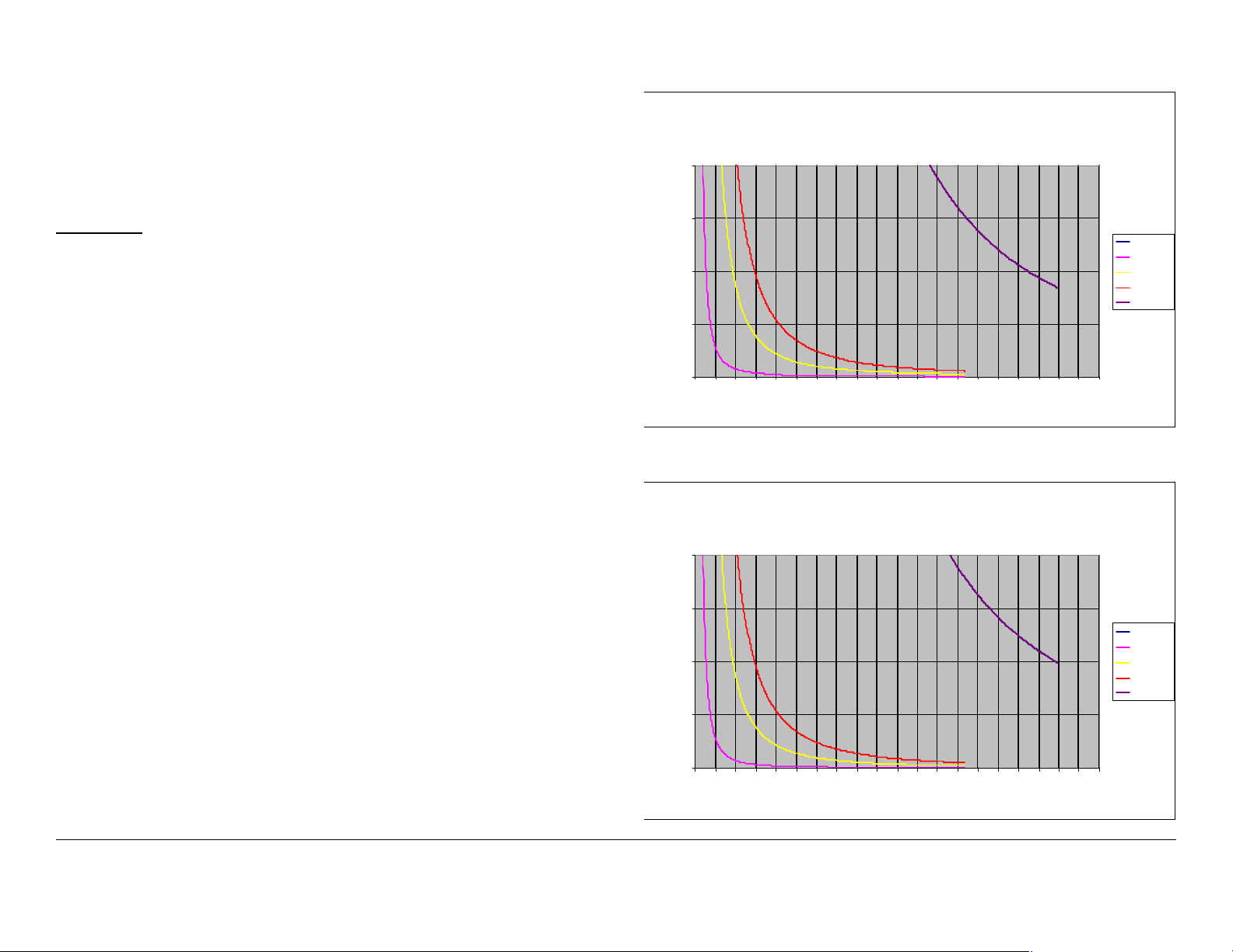
Figure 1: Analog Modulation
Estimate d Permissible Exposure
@ 2.7 Watt s Digital RF Power
for STRAT A 6.425 - 6.525 and 6.8875 - 7.1255 GHz.
2
Reference
FCC OET Bulletin 65, August 1997 - Evaluating Compliance with
FCC Guidelines for Human Exposure to Radio Frequency
Electromagnetic Fields
Figure 1 and Figure 2 show the maximum exposure distance for
various antennas. One plot provides the maximum permissible
output of the STRATA transmitter for analog modulation, and the
other plot for digital modulation.
MRC, in accordance with the requirements set forth by the FCC,
provides this information as a guide to the user. It is assumed
that the users of this equipment are licensed and qualified to
operate the equipment per the guidelines and recommendations
contained within the product user guides and in accordance with
any FCC rules that may apply.
1.5
1
0.5
Power Density (mW/cm^2)
0
0 2 4 6 8 10121416182022242628303234363840
Distance in Feet
Figure 2: Digital Modulation
Estimated Per missible Exposure
@ 4.0 Watt s Analog RF Power
for STRAT A 6.425 - 6.525 and 6.8875 - 7.1255 GHz.
2
1.5
1
0.5
Power Density (mW /cm^2)
0dBi
5dBi
16dBi
20dBi
35.7dBi
0dBi
5dBi
16dBi
20dBi
35.7dBi
0
0 2 4 6 8 10121416182022242628303234363840
Distance in Feet
iiSTRATA TX Operator’s Guide/Tech Ref Manual

The following table reflects the graphic representations above.
Tabl e 1:
Antenna
Gain (dBi)
020 7.87
5 35 13.7
16 112 44
20 560 220.4
37.5 1088 428.3
Minimum
Distance from
Antenna (cm)
Minimum Distance
from Antenna (inch)
iiiSTRATA TX Operator’s Guide/Tech Ref Manual

This page intentionally left blank.
ivSTRATA TX Operator’s Guide/Tech Ref Manual

Notices
About This Manual
Part number 400504-1
Revision C February 2007
The information in the manual applies to the Microwave Radio
Communications (MRC) STRATA TX System.
Copyright
The information in this manual may only be reproduced by the
purchaser strictly for its own internal use to the extent required
for its use of the product, and shall only be made available to
purchaser’s employees who need access to this material. No
part of this material, nor any copies hereof, shall in any manner
be disclosed, disseminated, or made available by purchaser or
its employees to any other person, firm, or entity without the
express prior written consent of Microwave Radio
Communications nor shall the same in any manner be modified
or published for resale without the express prior written
authorization of Microwave Radio Communications.
Proprietary Material
The information and design contained within this manual was
originated by and is the property of Microwave Radio
Communications. Microwave Radio Communications reserves
all patent proprietary design, manufacturing, reproduction use,
and sales rights thereto, and to any articles disclosed therein,
except to the extent rights are expressly granted to others. The
foregoing does not apply to vendor proprietary parts.
Microwave Radio Communications has made every effort to
ensure the accuracy of the material contained in this manual at
the time of printing. As specifications, equipment, and this
manual are subject to change without notice, Microwave Radio
Communications assumes no responsibility or liability
whatsoever for any errors or inaccuracies that may appear in this
manual or for any decisions based on its use. This manual is
supplied for information purposes only and should not be
construed as a commitment by Microwave Radio
Communications.
Quality Certification
Microwave Radio Communications is certified to ISO 9001:2000.
© 2007 Microwave Radio Communications
Microwave Radio Communications
101 Billerica Avenue - Bldg. 6
North Billerica, MA 01862-1256USA
TEL: 978.671.5700
FAX: 978.671.5800
Printed in U.S.A.
Regulatory Status
This product is certified to conform to CENELEC standards EN
55020, EN 55013, EN 50082-1, and EN 60950 and carries the
CE mark.
Authorized EU representative: Vislink PLC.
Notices-iSTRATA TX Operator’s Guide
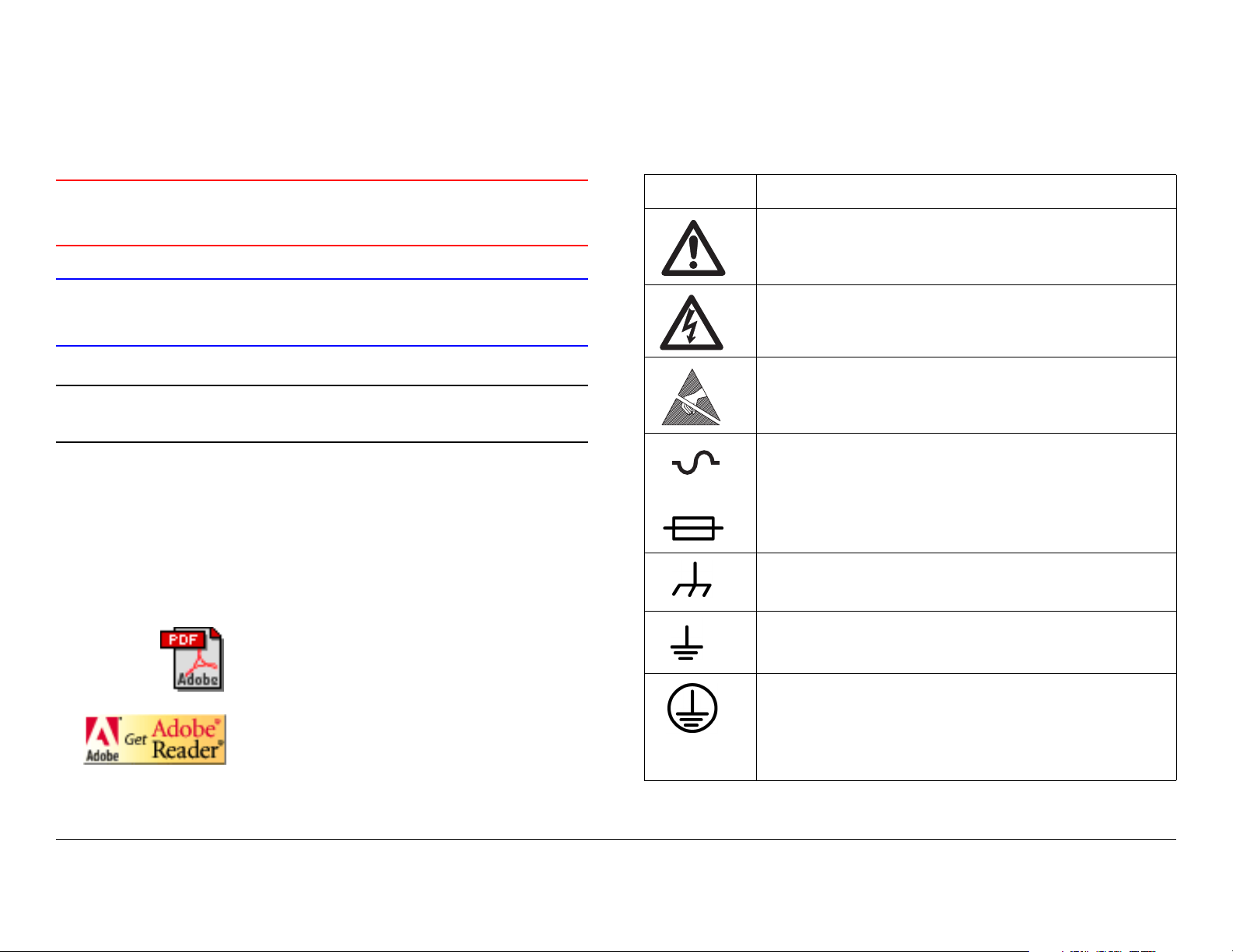
Conventions
Symbols Used
Pay special attention to information marked in one of the
following ways:
WARNING
CAUTION
Note
Notes provide additional information to assist you
in using and maintaining the equipment.
Follow WARNINGS closely to prevent
personal injury or death.
Follow CAUTIONS to prevent damage to
the equipment.
On-Line Viewing
Text displayed as blue contains a hypertext link. Click on the
hypertext to jump to that destination. Click on the
blue destination to return.
The following symbols are used on the equipment:
Symbol Meaning
WARNING: General Warning. Risk of Danger
WARNING: Risk of Electric Shock
WARNING: Electrostatic Discharge. Possible
Damage to Equipment
Fuse - Identifies fuses or their location.
- OR -
Frame or Chassis Ground - Identifies the frame or
chassis terminal.
Viewing this manual on-line
requires Adobe Acrobat,
version 4.0 or above.
Click on this icon to download your
FREE copy of Adobe Acrobat
Reader.
Earth Ground - Identifies the earth Ground Terminal
Protective Earth Ground - Identifies any terminal
which is intended for connection to an external
conductor for protection against electric shock in
case of a fault, or the terminal on a protective earth
electrode.
iiSTRATA TX Operator’s Guide

Warranty Information
Product Manufactured by MRC:
a. Products manufactured by MRC are warranted against
defects in material and workmanship for a period of two (2) years
from date of delivery as evidenced by MRC's packing slip or
other transportation receipt (unless otherwise noted).
b. MRC's sole responsibility under this warranty will be to either
repair or replace, at its option, any component which fails during
the applicable warranty period because of a defect in material or
workmanship, provided Buyer has promptly reported same to
MRC in writing. All replaced products and parts will become
MRC's property.
ordinary use; (2) if the product has been modified by Buyer or
has been repaired or altered outside MRC's repair facility, unless
MRC specifically authorizes such repairs or alterations in each
instance; or (3) where MRC serial numbers, warranty data or
quality assurance decals have been removed or altered.
e. Equipment shipped FOB from Microwave Radio
Communications shall become the property of the buyer upon
delivery and receipt from the carrier. Any damage in shipment
should be handled by the buyer directly with the carrier.
Immediately request the carrier’s inspection upon evidence of
damage during shipment. Do not return any Microwave Radio
Communications product to the factory until a Return Material
Authorization (RMA) number and shipping instructions have
been provided.
c. MRC will honor the warranty at the repair facility designated
by MRC. It is Buyer's responsibility to return, at its expense, the
allegedly defective product to MRC. Buyer must obtain a Return
Material Authorization (RMA) number and shipping instructions
from MRC prior to returning any product under warranty.
Transportation charges for the return of the product to Buyer will
be paid by MRC within the United States. For all other locations,
the warranty excludes all costs of shipping, customs clearance
and other related charges. If MRC determines that the product is
not defective within the terms of this warranty, Buyer will pay
MRC all costs of handling, transportation and repairs at the then
prevailing repair rates.
d. All the above warranties are contingent upon proper use of
the product. These warranties will not apply (1) if adjustment,
repair, or product or parts replacement is required because of
accident, unusual physical, electrical or electromagnetic stress,
neglect, misuse, failure of electric power, environmental controls,
transportation, failure to maintained properly or otherwise in
accordance with MRC specifications, or abuses other than
f. No person, including any dealer, agent or representative of
MRC is authorized to assume for MRC any other liability on its
behalf except as set forth herein. If any payment is due MRC for
services performed hereunder, it will be subject to the same
payment terms as the original purchase.
Products Manufactured By Others:
For products not manufactured by MRC, the original
manufacturer's or licensor's warranty will be assigned to Buyer to
the extent permitted by the manufacturer or licensor and is in lieu
of any other warranty, expressed or implied. For warranty
information on a specific product, a written request should be
made to MRC.
All Products:
THE FOREGOING WARRANTIES AND REMEDIES ARE
EXCLUSIVE AND ARE IN LIEU OF ALL OTHER EXPRESS OR
IMPLIED WARRANTIES, OBLIGATIONS, AND LIABILITIES ON
THE PART OF MRC. EXCEPT FOR THE EXPRESS
iiiSTRATA TX Operator’s Guide

WARRANTIES STATED HEREIN, MRC DISCLAIMS ALL
WARRANTIES ON PRODUCTS FURNISHED HEREUNDER,
INCLUDING, WITHOUT LIMITATION, ALL IMPLIED
WARRANTIES OF MERCHANTABILITY AND FITNESS FOR A
PARTICULAR PURPOSE. MRC WILL HAVE NO
RESPONSIBILITY FOR ANY PARTICULAR APPLICATION
MADE OF ANY EQUIPMENT.
Any description of equipment, whether in writing or made orally
by MRC or its agents, specification sheets, models, bulletins,
drawings, or similar materials used in connection with Buyer's
order are for the sole purpose of identifying the equipment and
will not be construed as an express warranty. Any suggestions
by MRC or its agents regarding use, application or suitability of
the equipment will not be construed as an express warranty. No
warranties may be implied from any course of dealing or usage
of trade. Buyer agrees that the exclusion of all warranties, other
than those expressly provided herein, is reasonable.
ivSTRATA TX Operator’s Guide

Contents
About This Manual - - - - - - - - - - - - - - - - - - - - - - - - i
Copyright - - - - - - - - - - - - - - - - - - - - - - - - - - - - - - - i
Proprietary Material - - - - - - - - - - - - - - - - - - - - - - - i
Quality Certification - - - - - - - - - - - - - - - - - - - - - - - i
Regulatory Status - - - - - - - - - - - - - - - - - - - - - - - - - i
Conventions - - - - - - - - - - - - - - - - - - - - - - - - - - - - - - - ii
On-Line Viewing - - - - - - - - - - - - - - - - - - - - - - - - - - ii
Symbols Used- - - - - - - - - - - - - - - - - - - - - - - - - - - - - - ii
Warranty Information - - - - - - - - - - - - - - - - - - - - - - - - - iii
Product Manufactured by MRC: - - - - - - - - - - - - - - - iii
Products Manufactured By Others:- - - - - - - - - - - - - iii
All Products: - - - - - - - - - - - - - - - - - - - - - - - - - - - - iii
Introduction - - - - - - - - - - - - - - - - - - - - - - - - - 1-1
Chapter Overview - - - - - - - - - - - - - - - - - - - - - - - - - 1-1
What This Manual Covers - - - - - - - - - - - - - - - - - - - 1-1
How It’s Organized - - - - - - - - - - - - - - - - - - - - - - - - 1-1
For Whom It’s Written - - - - - - - - - - - - - - - - - - - - - - 1-2
Related Documents - - - - - - - - - - - - - - - - - - - - - - - - 1-2
Ordering Documentation - - - - - - - - - - - - - - - - - - - - 1-2
Calling for Service - - - - - - - - - - - - - - - - - - - - - - - - - 1-2
Supported Repairs - - - - - - - - - - - - - - - - - - - - - - - - 1-3
Tell Us What You Think! - - - - - - - - - - - - - - - - - - - - 1-3
Product Description- - - - - - - - - - - - - - - - - - - 2-1
Chapter Overview - - - - - - - - - - - - - - - - - - - - - - - - - 2-1
System Description - - - - - - - - - - - - - - - - - - - - - - - - 2-1
System Options - - - - - - - - - - - - - - - - - - - - - - - - 2-2
Single Unit Systems - - - - - - - - - - - - - - - - - - - - - 2-3
Multi-Unit Systems - - - - - - - - - - - - - - - - - - - - - - 2-3
Remote Control Options - - - - - - - - - - - - - - - - - - 2-3
Antenna and Power Options - - - - - - - - - - - - - - - 2-3
Mounting and Deployment Options - - - - - - - - - - - 2-5
System Integration - - - - - - - - - - - - - - - - - - - - - - 2-5
System Components - - - - - - - - - - - - - - - - - - - - - - - 2-7
STRATA TXU - - - - - - - - - - - - - - - - - - - - - - - - - - 2-7
STRATA TCU - - - - - - - - - - - - - - - - - - - - - - - - - - 2-7
STRATA ACU - - - - - - - - - - - - - - - - - - - - - - - - - - 2-8
STRATA Remote Control Panels - - - - - - - - - - - - 2-8
TXU and TCU Configurations - - - - - - - - - - - - - - - - - 2-9
Typical System Configurations - - - - - - - - - - - - - - - 2-12
For More Information - - - - - - - - - - - - - - - - - - - - - - 2-12
Routine Operation - - - - - - - - - - - - - - - - - - - - 3-1
Chapter Overview - - - - - - - - - - - - - - - - - - - - - - - - - 3-1
Overview of Controls, Indicators, and Connectors - - - 3-2
TXU Controls, Indicators, and Connectors - - - - - - 3-2
TCU Controls, Indicators, and Connectors- - - - - - 3-5
ACU Controls, Indicators, and Connectors- - - - - - 3-8
STRATA Standard Remote Control Panel Controls,
Indicators, and Connectors- - - - - - - - - - - - - - - - - 3-9
STRATA Aircraft Remote Control Panel Controls,
Indicators, and Connectors- - - - - - - - - - - - - - - - - 3-9
Preparing for Operation - - - - - - - - - - - - - - - - - - - - 3-10
Mobile Installation - - - - - - - - - - - - - - - - - - - - - - 3-10
Portable Deployment - - - - - - - - - - - - - - - - - - - - 3-10
Powering the STRATA TX System - - - - - - - - - - 3-12
Single TCU Power Up and Power Down - - - - - - 3-13
Single TXU Power up and Power Down- - - - - - - 3-14
TXU and TCU Power Up and Power Down -
Co-Located- - - - - - - - - - - - - - - - - - - - - - - - - - - 3-15
TXU and TCU Power Up and Power Down - Separate
Locations - - - - - - - - - - - - - - - - - - - - - - - - - - - - 3-17
Using the STRATA TX Screens - - - - - - - - - - - - - - - 3-19
TXU and/or TCU Monitoring Operations - - - - - - - - - 3-20
Using the Monitor Screens in MPEG Output Mode 3-20
Contents-1STRATA TX Operator’s Guide

Using the Monitor Screens in Ext IF Input Mode 3-22
Using the Monitor Screens in COFDM - IF Mode 3-23
Using the Monitor Screens in COFDM ASI In Mode 3-24
Using the Monitor Screens in Analog - IF Mode - 3-25
Using the Monitor Screens in DVB-S Mode- - - - 3-26
TXU and/or TCU Control Operations - - - - - - - - - - - 3-27
Changing a Preset - - - - - - - - - - - - - - - - - - - - - 3-29
Setting a Channel - - - - - - - - - - - - - - - - - - - - - - 3-30
Setting Power Output - - - - - - - - - - - - - - - - - - - 3-31
Controlling TCU to TXU DC Power on Coax - - - 3-32
Front Panel vs. STRATA TX Configurator Settings - 3-34
Troubleshooting - - - - - - - - - - - - - - - - - - - - - 4-1
Chapter Overview - - - - - - - - - - - - - - - - - - - - - - - - - 4-1
Status LED - - - - - - - - - - - - - - - - - - - - - - - - - - - - - - 4-1
Messages on Display- - - - - - - - - - - - - - - - - - - - - - - 4-1
Error Codes - - - - - - - - - - - - - - - - - - - - - - - - - - - - - 4-3
Primary Error Code- - - - - - - - - - - - - - - - - - - - - - 4-3
Error Status - - - - - - - - - - - - - - - - - - - - - - - - - - 4-8
Unit ID - - - - - - - - - - - - - - - - - - - - - - - - - - - - - - 4-8
Operational Problems - - - - - - - - - - - - - - - - - - - - - - 4-8
Channels & Frequencies - - - - - - - - - - - - - - - A-1
Appendix Overview - - - - - - - - - - - - - - - - - - - - - - - - A-1
Initial Factory Presets - - - - - - - - - - - - - - - - - - - - - - A-1
3.4 to 3.8 GHz Channel Plan - - - - - - - - - - - - - - - A-1
4.4 to 5.0 GHz Channel Plan - - - - - - - - - - - - - - - A-2
6.4 to 7.1 GHz Channel Plan - - - - - - - - - - - - - - - A-2
6.9 to 7.5 GHz Channel Plan - - - - - - - - - - - - - - - A-3
7.4 to 8.0 GHz Channel Plan - - - - - - - - - - - - - - - A-3
7.8 to 8.5 GHz Channel Plan - - - - - - - - - - - - - - - A-4
8.2 to 8.9 GHz Channel Plan - - - - - - - - - - - - - - - A-4
10.0 to 10.7 GHz Channel Plan - - - - - - - - - - - - - A-5
10.5 to 11.2 GHz Channel Plan - - - - - - - - - - - - - A-5
10.8 to 11.5 GHz Channel Plan - - - - - - - - - - - - - A-6
12.7 to 13.25 GHz Channel Plan- - - - - - - - - - - - - A-6
Glossary - - - - - - - - - - - - - - - - - - - - - - - - - - - B-1
Contents-2STRATA TX Operator’s Guide

1
Introduction
1.1 Chapter Overview
This chapter will introduce you to the Operator’s Guide: what it
covers, how it’s organized, and for whom it’s written.
1.2 How to Use This Manual
This manual was prepared to be viewed on a Windows-based
PC. A pdf file for this manual is provided on the CD ROM
delivered with each STRATA Transmitter (TX) System. The CD
ROM contains pdf files for the Operator’s Guide, the Technical
Reference Manual, and the Quick Reference Cards. Hardcopies
of the Operator’s Guide, the Technical Reference Manual, and
the Quick Reference Cards are also delivered with each
STRATA TX System.
Viewing of this manual on-line requires Adobe Acrobat, Version
4.0 or above. Click on the following icon to download your FREE
copy of Adobe Acrobat Reader.
1.3 What This Manual Covers
This manual describes how to operate the STRATA TX
Transmitter System.
For information on Installation, Repair, Replacement Parts, and
Theory of Operation, refer to the STRATA TX Technical
Reference Manual.
This manual also covers various configurations of the STRATA
TX System. Your STRATA TX System will consist of one of the
following configurations:
• A Standalone Transmitter Control Unit (TCU)
• A Standalone Transmitter Unit (TXU)
• A TCU and TXU.
Your TX System may be mounted on a tripod or may be mounted
in a vehicle or in an aircraft. Your TX System may also include an
optional MRC AC to DC Converter Unit (ACU).
If your system is mounted in a vehicle or in an aircraft, it may
include an optional MRC Remote Control Panel or Aircraft
Remote Control Panel. This manual provides coverage for all of
these various configurations.
When viewing this manual on-line, text displayed as blue
contains a hypertext link. Click on the blue hypertext link to
jump to that destination. If the destination link is also blue, click
on the blue destination link to return.
Introduction 1-1STRATA TX Operator’s Guide
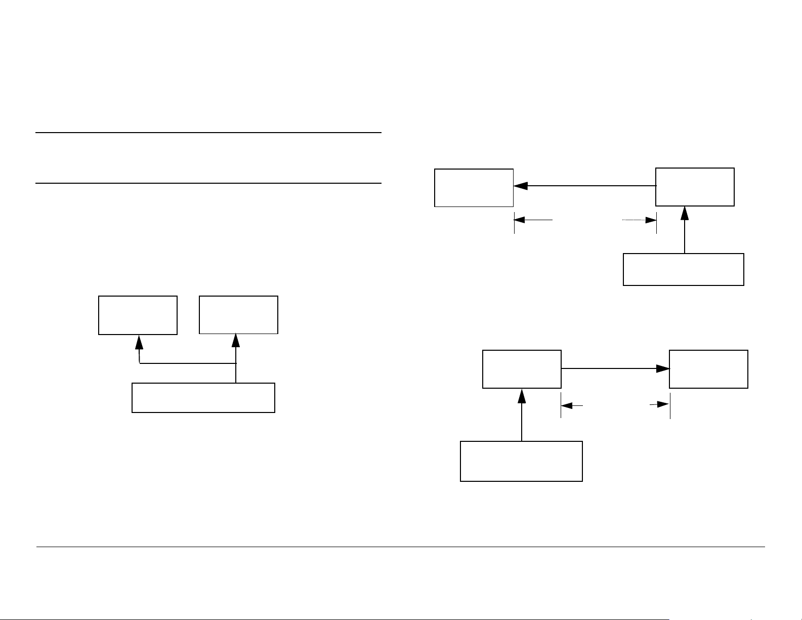
1.4 How It’s Organized
The manuals for the STRATA TX System are organized as
follows:
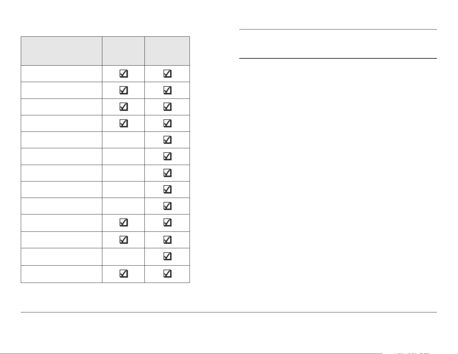
Chapter
Introduction
Product Description
Routine Operation
Troubleshooting
Operator’s
Guide
Technical
Reference
Manual
Note
The Technical Reference Manual contains
everything in the Operator’s Guide, plus additional
technical content.
1.5 For Whom It’s Written
This manual is intended for use by personnel assigned to
operate the STRATA TX System. Users of this manual should
already be familiar with basic concepts of radio, video, and
audio.
Advanced Operation
Installation
Repair
Replacement Parts
Theory of Operation
Appendix A - Channels
& Frequencies
Appendix B - Glossary
Appendix C Configurator Reference
Appendix D Specifications
1.6 Related Documents
• STRATA TX System Technical Reference Manual
(part no. 400505-1)
• STRATA TX System Quick Reference Card
(part no. 400506-1)
• STRATA Aircraft Remote Control Panel Operator’s Guide
(part no. 400490)
• STRATA Remote Control Panel Operator’s Guide
(part no. 400489)
1.7 Ordering Documentation
Any of the above manuals may be ordered by contacting MRC
Customer Service:
Business Hours: Monday - Thursday
8:00 AM - 7:00 PM Eastern Time (US)
(0800 - 1900 hrs US ET)
Introduction 1-2STRATA TX Operator’s Guide

Friday
Telephone: 800-490-5700 (Press 4)
8:00 AM - 5:00 PM Eastern Time (US)
(0800 - 1700 hrs US ET)
Telephone: 800-490-5700 (Press 3)
978-671-5700 (Press 3)
Fax: 978-671-5800
E-mail customerservice@mrcbroadcast.com
When contacting Customer Service, please have the following
information available:
• Model number and serial number of the unit. This is
located on a label on the bottom of each unit.
• Approximate purchase date.
• Radio version, which appears on the TXU or TCU
alphanumeric display at startup.
or
• Firmware versions displayed on the Main page of the
STRATA TX Configuration Utility, when the STRATA TX
Configuration Utility is connected to the TXU or TCU.
978-671-5700 (Press 4)
Fax: 978-671-5800
E-mail: technicalsupport@mrcbroadcast.com
After regular business hours and on weekends and holidays, you
can also reach our expert staff as follows:
Telephone: 978-671-5929
Your call will be automatically forwarded to the on-call Technical
Support specialist.
When contacting Technical Support, please have the following
information available:
• Model number and serial number of the unit. This is
located on a label on the bottom of each unit.
• Approximate purchase date.
• Radio version, which appears on the TXU or TCU
alphanumeric display at startup.
or
1.8 Calling for Service
MRC Technical Support is available 24 hours a day, 7 days a
week. During regular business hours you can reach our expert
staff directly.
Business Hours: Monday - Friday
8:00 AM - 7:00PM Eastern Time (US)
(0800 - 1900 hrs US ET)
Introduction 1-3STRATA TX Operator’s Guide
• Firmware versions displayed on the Main page of the
STRATA TX Configuration Utility, when the STRATA TX
Configuration Utility is connected to the TXU or TCU.
1.9 Supported Repairs
The STRATA TX System, including the TXU, TCU, and optional
ACU, is designed to be compact, rugged and reliable.

The TXU and TCU require specialized test equipment to
calibrate amplitude and frequency characteristics after repair. In
addition, sealing the TXU, TCU, or optional ACU enclosures
after repair requires exacting techniques and special fixtures to
ensure weather resistance of the units.
Therefore, there are NO supported field repairs to either the
TXU, TCU, or ACU.
Return the entire unit for factory repair.
If you attempt field repair, you risk damaging your
equipment. If your equipment is under warranty, you may also
affect your warranty coverage.
1.10 Tell Us What You Think!
We’d appreciate any comments or suggestions you have about
this manual. The more feedback we get, the better the manuals
get!
If you’re viewing this manual electronically, it’s easy - just click on
the link below send us an E-mail.
Feedback
Or, you can E-mail our Technical Support team at:
technicalsupport@mrcbroadcast.com
Be sure to tell us what product you’re writing about, and which
manual - the Operator’s Guide, the Quick Reference Card, or the
Technical Reference Manual.
Introduction 1-4STRATA TX Operator’s Guide

2
Product Description
2.1 Chapter Overview
This chapter provides an overall description of the STRATA TX
System, its components, and its capabilities.
Here are the topics covered:
2.2 System Description
The STRATA TX System is a highly reliable, flexible, and
compact portable microwave transmitter system ideal for tripod,
airborne, or mobile installations. A typical STRATA TX System is
composed of the Transmitter Unit (TXU) and the Transmitter
Control Unit (TCU), as shown in Figure 2-1 on page 2-2. This
modular architecture allows you the maximum flexibility in
configuration, siting, and operation.
The STRATA TX System key features are:
Topic Page
System Description 2-1
System Options 2-2
Single Unit Systems 2-3
Multi-Unit Systems 2-3
Remote Control Options 2-3
Antenna and Power Options 2-3
Mounting and Deployment Options 2-5
System Integration 2-5
System Components 2-7
STRATA TXU 2-7
STRATA TCU 2-7
STRATA ACU 2-8
STRATA Remote Control Panels 2-8
TXU and TCU Configurations 2-9
Typical System Configurations 2-12
For More Information 2-12
• Analog, Digital, or Analog/Digital Switchable
• MPEG Encoding (4:2:0, 4:2:2)
• COFDM Modulation with Forward Error Correction and
Selectable Guard Band Interval
• Digital Modulation for QPSK, 16 QAM, and 64 QAM
• NTSC or PAL Modulation with Audio (4 mono or 2 stereo)
• Tripod, Half Rack, or Full Rack Mounts
• Front Panel Local Control
• Remote Control
• Bands from 3.4 to 13.25 GHz
Product Description 2-1STRATA TX Operator’s Guide/Tech Ref Manual
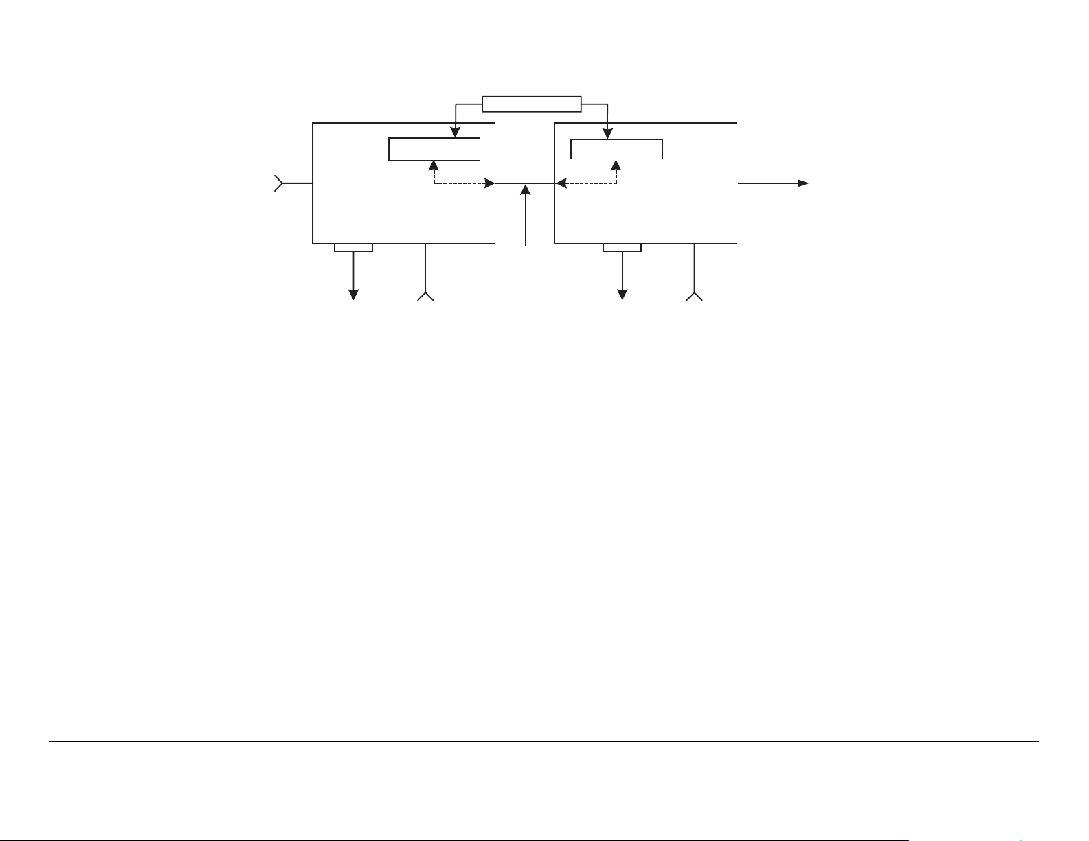
Figure 2-1: STRATA TX System Block Diagram
1.84 MHz OOK Tone
y NTSC
y PAL
y SDI
y ASI
y IF
IN
RS-232
Telemetry
TCU TXU
DC Power and/or IF
+28 VDC
The STRATA TX System TXU and the TCU may be operated in
stand-alone configurations depending upon specific video
applications.
2.2.1 System Options
The STRATA TX System can be ordered configured for 1 of 11
specific RF bands as follows:
• 3.4 to 3.9 GHz
• 4.4 to 5.0 GHz
• 6.4 to 7.1 GHz
• 6.9 to 7.5 GHz
• 7.4 to 8.1 GHz
• 7.8 to 8.5 GHz
• 8.2 to 8.9 GHz
Telemetry
RF Out
RS-232
+28 VDC
• 10.0 to 10.7 GHz
• 10.5 to 11.2 GHz
• 10.8 to 11.5 GHz
• 12.7 to 13.25 GHz
MRC is constantly working to expand and upgrade the
capabilities of the STRATA TX System. Consult your Sales
Representative or contact the factory for the latest band
availability.
The STRATA TX System (typically) consists of the following
components:
TXU The Transmitter Unit (TXU) can be equipped with either an
FM Modulator or COFDM/MPEG module, but not both. A High
Power Unit (HPU) is also contained within the TXU housing to
increase RF power output.
Product Description 2-2STRATA TX Operator’s Guide/Tech Ref Manual Product Description 2-2STRATA TX Operator’s Guide/Tech Ref Manual

TCU The Transmitter Control Unit (TCU) can be equipped with
either an FM Modulator or COFDM/MPEG module, or both.
ACU The optional AC to DC Power Converter (ACU) provides
+28 VDC power from an AC power source to power one or more
units in a system.
Remote Control Panels Optional Remote Control Panels are
available to allow remote control of the STRATA TX System from
an instrument panel during airborne or mobile operations.
2.2.2 Single Unit Systems
The TXU or TCU may be used independently in single-unit
applications as follows:
• The TXU may be used as a stand-alone transmitter
accepting an IF input.
• The TXU may be used as a stand-alone transmitter
featuring FMT modulation or MPEG and COFDM.
• The TCU can be separated from the TXU in applications
where the transmitter needs to be placed in another
location.
2.2.4 Remote Control Options
For portable mobile or airborne operations, the STRATA TX
System may be controlled by one of two models of Remote
Control Panels. The Remote Control Panels are mounted in
mobile racks or aircraft instrument panels and are connected via
an RS-232 cable between the Remote Control Panel and the
STRATA TX System.
2.2.5 Antenna and Power Options
The flexible architecture of the STRATA TX System allows a
number of options for both the transmit antenna and the power.
Antenna Options The STRATA TX System is fully compatible
with the MRC family of transmit antennas, including:
• The TCU may be used as a stand-alone unit used for
FMT modulation or MPEG and COFDM, or both FMT
modulation and MPEG and COFDM.
2.2.3 Multi-Unit Systems
The TXU and TCU can be configured as part of an integrated
system as follows:
• The TCU may contain the FMT modulator and MPEG/
COFDM module supplying an IF signal to a TXU
containing only the RF transmitter.
• The TXU may contain the RF modulator or MPEG/
COFDM module supplying an RF signal directly to the
transmitter antenna.
Product Description 2-3STRATA TX Operator’s Guide/Tech Ref Manual
• OmniPole omnidirectional
• Megahorn compact horn
• SectorScan flat panel
• MicroScan parabolic
• Ellipse parabolic
Contact your Sales Representative to explore the wide array of
antenna choices available.
CAUTION
To prevent damage to your STRATA TX
System, MRC recommends using a +28
VDC power supply. Do not exceed +36
VDC input power or damage will occur.
Power Options The STRATA TX System configurations
operate on +28 VDC power, supplied externally. This DC power
can be supplied by the optional STRATA ACU, or from another
DC power source. Contact your Sales Representative for the
latest details.
Note
If the TXU and TCU are co-located, power must be supplied to
each unit through their individual power connectors from the
same power source. See Figure 2-2. Do not use DC on coax to
power the TXU or TCU when the units are co-located.
A TCU and TXU are defined as being “co-located”
when the TXU and TCU are physically separated
by not greater than 6 feet.
Refer to the “Installation” Chapter on page 6-1 (part of the
STRATA TX Technical Reference Manual only) for additional
information.
For those applications that use a TCU in a standalone mode, i.e.,
to generate ASI or DVB-S signals, DC power from the TCU to
the TXU or from the TXU to the TCU cannot be used.
Figure 2-3: Powering the TXU from the TCU
STRATA
Coax
TXU
Up to 600 ft.
(180 m)
STRATA
TCU
Power
Cable
Figure 2-2: Powering the TXU and TCU Independently
STRATA
TXU
DC Power (+28 V)
If your installation calls for separating the TXU and TCU, the
TXU is powered by DC supplied by the TCU or the TCU is
powered by DC supplied by the TXU. The DC power is
superimposed on the coaxial cable connected between the units.
See Figure 2-3 and Figure 2-4.
The DC input voltage to the unit co-located with the DC power
supply must be greater than +24 VDC.
STRATA
TCU
Branched
Power Cable
DC Power (+28 V)
Figure 2-4: Powering the TCU from the TXU
Coax
STRATA
TXU
Up to 600 ft.
(180 m)
DC Power (+28 V )
STRATA
TCU
Product Description 2-4STRATA TX Operator’s Guide/Tech Ref Manual

DC power superimposed on the coaxial cable between a TCU
and a TXU can be supplied from either the TCU or TXU,
depending upon the location of the DC power supply. Coaxial
cable length/voltage limitations exist when powering from either
the TXU or TCU. These limitations are based on cable size, DC
voltage input, cable resistance, and cable length. A maximum
length of 600 feet (180 meters) between the TXU and TCU is
supported. Contact MRC Technical Support for more information
on cable requirements.
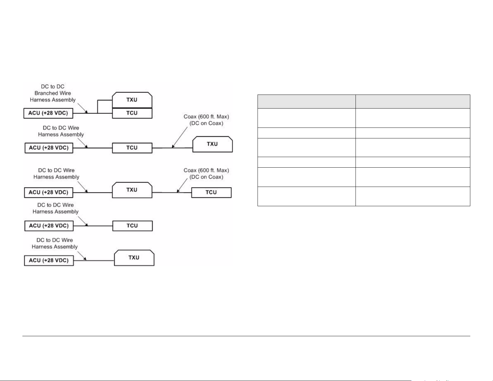
DC power required for a STRATA TX System depends upon the
TX System configuration, i.e., if the TXU or TCU are operated in
a standalone mode, if the TXU and TCU are co-located, or if the
TXU and TCU are mounted in separate locations. See Figure 2-
5 on page 2-6 for the various STRATA TX System configurations
available.
For TX Systems that use DC power sources other than a
STRATA ACU, contact MRC Technical Support for additional
power information.
The TXU and TCU will usually be mounted in a MRC universal
mounting bracket. The bracket is attached to a tripod using a
mounting plate and quick release.
The cabling between the TXU and TCU is typically left in place
and the power, antenna, and audio/video connections are
removed at the end of each deployment.
2.2.7 System Integration
System Communication When the TXU and TCU are
connected, they automatically communicate via signals
superimposed on the coaxial cable between the two units. This
allows them to share information on installed hardware, preset
configurations, current status, and alarms.
System Operation Once the TXU and TCU are connected and
communicating, the units work seamlessly together. System
settings can be selected and modified from the front panel of
either unit, regardless of which unit holds the hardware being
configured.
2.2.6 Mounting and Deployment Options
The STRATA TX offers a number of options for either mobile or
portable applications.
For more details on installation of the STRATA TX in various
applications, see the “Installation” Chapter on page 6-1 (part of
the STRATA TX Technical Reference Manual only).
Mobile Installation For mobile applications such as in a vehicle
or in an aircraft, the STRATA TX System is usually mounted in an
MRC fixed mounting bracket and is installed in a bulkhead or
compartment. The cabling is permanently installed and power
comes from aircraft or vehicle power.
Portable Deployment In portable applications, the STRATA TX
System will be moved from place to place and set up each time.
Product Description 2-5STRATA TX Operator’s Guide/Tech Ref Manual
System Configuration The STRATA TX System offers two
levels of system configuration, designed to match the needs of
different personnel.
For the field operator, the STRATA TX System has up to 9
Presets that can be selected from the front panel. Each Preset
controls key parameters such as modulation, frequency, and
audio and video settings. Additional settings that are front panelcontrolled include band, channel, offset, and filtering.
For the advanced operator and technical staff, the STRATA TX
Configurator software allows complete control of all parameters
in the STRATA TX System. The STRATA TX Configurator
software runs on a Windows-based PC and connects to either
the TXU or the TCU via an RS-232 serial interface cable.
Interfacing a PC to either the TXU or TCU in a connected system
gives you complete control of both units. You can read the
current settings, program new settings, or return the units to their
factory default settings. The STRATA TX Configurator software
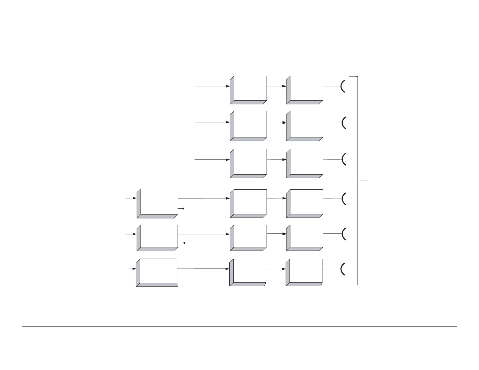
Figure 2-5: STRATA TX System Options
automatically detects what hardware is installed in the system
and assigns the appropriate configuration to the correct
hardware, regardless of which unit holds the hardware being
configured.
NTSC or PAL Analog Video
with 4 Audio Channels Available
SDI, ASI, NTSC or PAL
& Digitial/Analog Audio
Digital Video + Audio
70 MHz IF Output Only
SDI, ASI, NTSC or PAL
& Digitial/Analog Audio
TCU
COFDM / MPEG
& FMT
TCU
COFDM / MPEG
ASI Monitor
ASI Monitor
TXU
RF/IF Only
TXU
FMT Option
TXU
COFDM / MPEG
Option
TXU
RF/IF Only
TXU
RF/IF Only
HPU
(OPTIONAL)
HPU
(OPTIONAL)
HPU
(OPTIONAL)
HPU
(OPTIONAL)
HPU
(OPTIONAL)
1.9 to 2.5 GHz
or 2.3 to 2.7 GHz
RF Output
Analog Video + Audio
TCU
FMT Only
TXU
RF/IF Only
RXU
HPU
(OPTIONAL)
RXU
Product Description 2-6STRATA TX Operator’s Guide/Tech Ref Manual
2.3 System Components
This section will provide more details about each the
components of a STRATA TX System:
•STRATA TXU
• STRATA TCU
•STRATA ACU
• STRATA Remote Control Panels
For details on connections between the STRATA TX System
components, refer to the “Installation” chapter (part of the
STRATA TX Technical Reference Manual only).
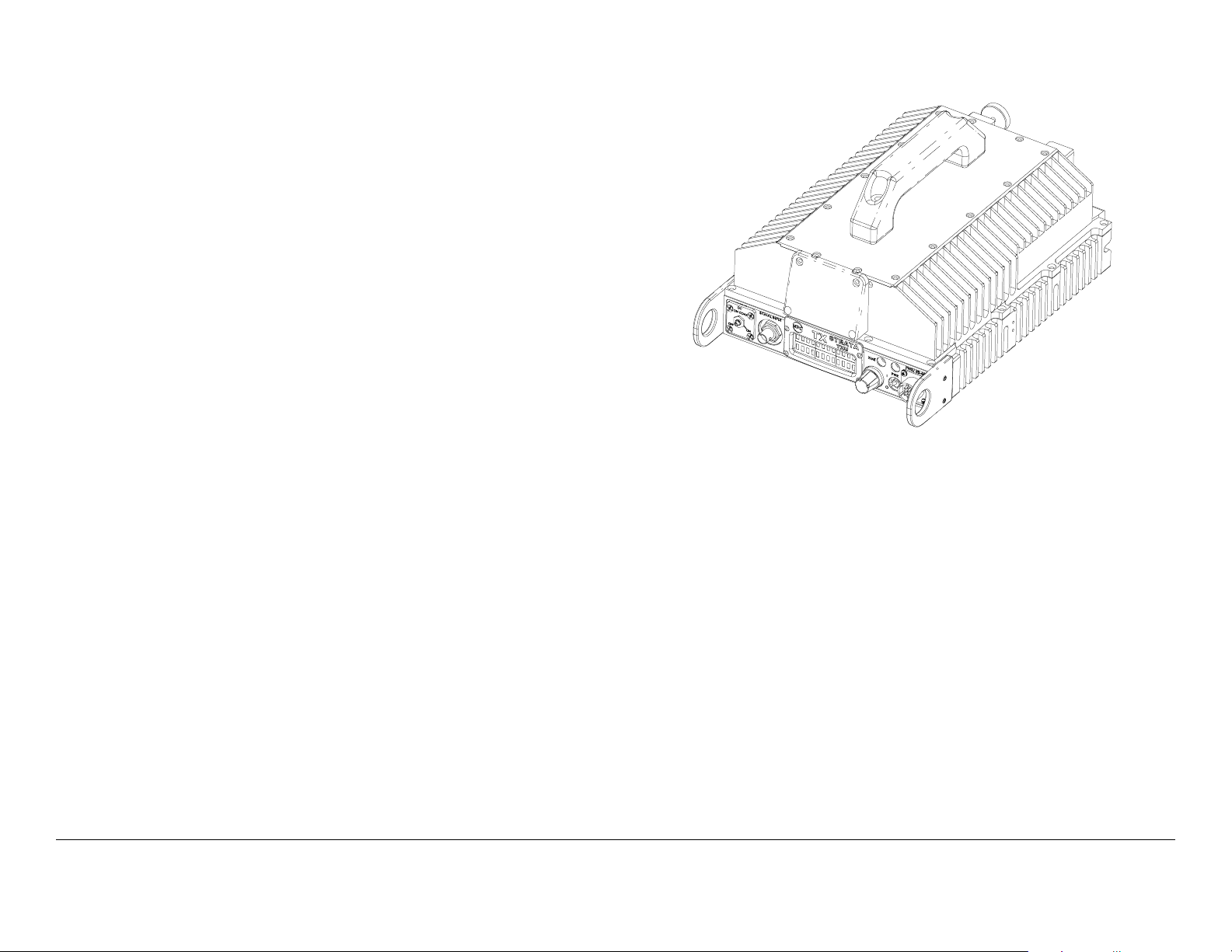
2.3.1 STRATA TXU
The TXU (See Figure 2-6) always contains an IF/RF module that
accepts either a 70 MHz COFDM, FMT IF, or external 70 MHz
input signal and up-converts these signals to the required RF
band. The RF frequency synthesizer circuit included in the IF/RF
unit, in conjunction with the command and control power supply
module, provides the means to channelize RF video and audio
signals in the TX System RF band.
Figure 2-6: STRATA TXU
As noted previously, the TXU may also include either an MPEG/
CODFM or FMT module (but not both), in which case the TXU
serves as a stand-alone digital or analog video microwave
transmission system.
The TXU, with either an analog (FMT) or digital (MPEG/COFDM)
module, is integrated in the same housing as the HPU
components. This provides the ability to incorporate high RF
power output (12 watts of saturated RF power) into a single
analog or digital transmitter assembly.
Standard U.S. FCC band plans, as well as customer-created
channel plans, may be customized using the STRATA TX
Configurator software.
Product Description 2-7STRATA TX Operator’s Guide/Tech Ref Manual
2.3.2 STRATA TCU
The TCU (See Figure 2-7 on page 2-8) may contain either
analog or digital or both analog and digital video modulation
modules. Where an application might initially employ only
analog video transmission but expects to migrate to dual,
switchable, analog and digital operation, the TCU may be
upgraded to add the MPEG/COFDM module to add this
capability.
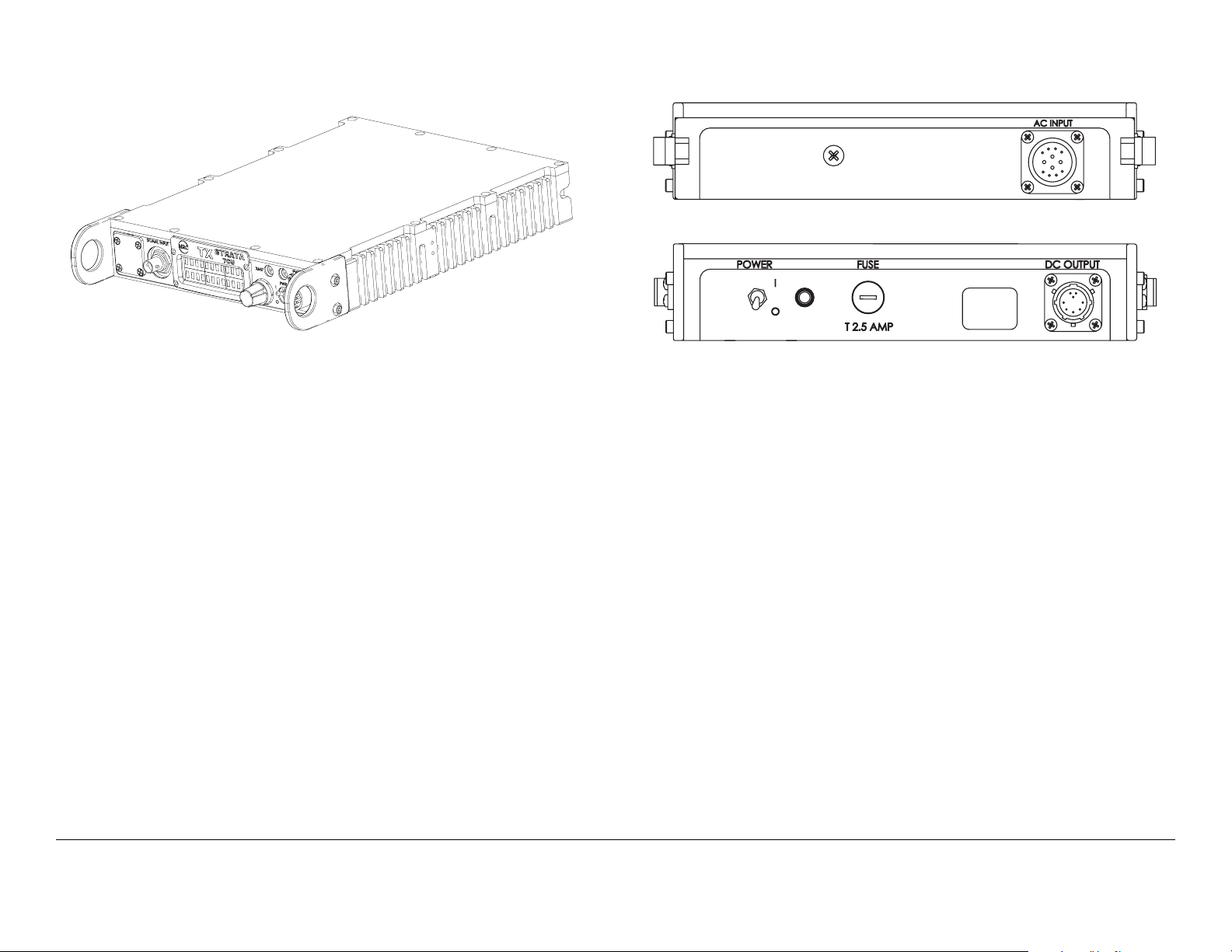
Figure 2-7: STRATA TCU
OUTPUT
< >
DC
Figure 2-8: AC to DC Converter
< >
DC
OUTPUT
Where only digital or analog video transmission is desired, the
MPEG/COFDM or FMT modules may be installed in a TXU,
thereby eliminating the need for a TCU. The STRATA TX design
does not permit splitting digital and analog video modulator
modules between a TXU and a TCU.
A TCU may also consist of a stand-alone configuration whereby
either or both MPEG/COFDM and FMT modules may be used
independent of the TXU. This configuration permits use of a TCU
equipped with analog and/or digital video modulation modules
for a variety of signal input and output configurations, including a
digital option using NTSC or PAL composite video input and ASI
(digital) signal output.
2.3.3 STRATA ACU
For fixed or portable deployment applications, the STRATA TX
System may be powered by the optional AC to DC Converter
(ACU). See Figure 2-8.
The ACU installs as part of an integrated stack for either tripod or
fixed applications. The ACU may also be used to power the TXU
or TCU only when a TXU and TCU are not co-located. In this
case, the TXU would receive DC power from the TCU or the
TCU would receive DC power from the TXU superimposed on
the coaxial cable connected between the units.
In standalone TXU or TCU operations, the optional ACU may be
used to supply DC power directly to the applicable unit. In the
case where a TXU and a TCU are co-located, it is recommended
that both the TXU and TCU be powered directly from the ACU in
lieu of supplying DC power from the TCU to the TXU or from the
TXU to the TCU via the coaxial cable connected between the
units.
2.3.4 STRATA Remote Control Panels
For mobile or airborne operations, two Remote Control Panel
models are currently available. Contact your Sales
Representative for the latest information.
Product Description 2-8STRATA TX Operator’s Guide/Tech Ref Manual
Both Remote Control Panel models provide simplified transmit
operations by allowing the operator or pilot to select either
analog or digital pre-configured Presets, Channels, and Offsets,
depending upon the required operating mode.
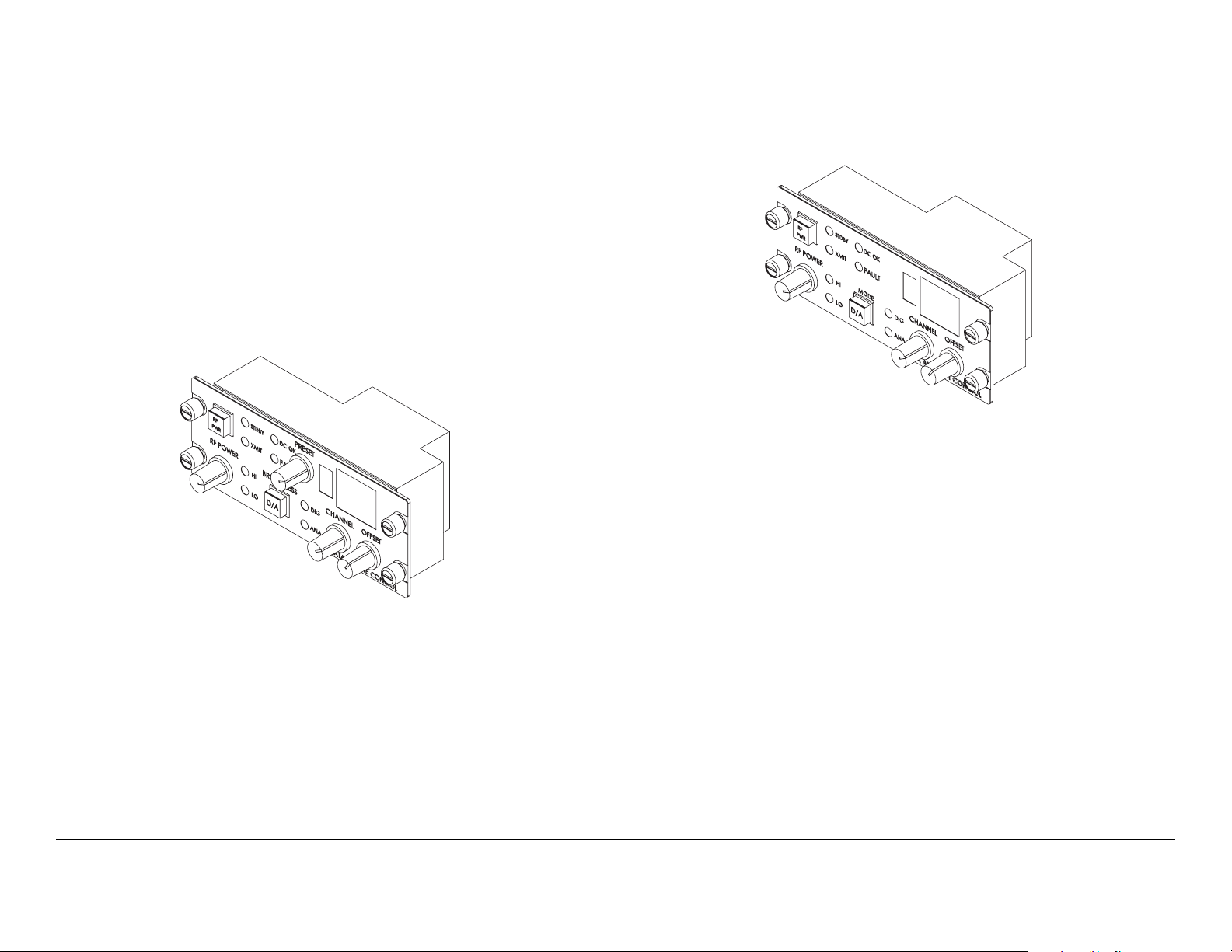
Standard Remote Control Panel The standard STRATA
Remote Control Panel (See Figure 2-9) provides instrument
panel remote control of the STRATA TX System for mobile
operations and features 9 selectable Presets.
For additional information, refer to the STRATA Remote Control
Panel Operator’s Guide (part no. 400489).
Figure 2-9: Standard Remote Control Panel
For additional information, refer to the STRATA Aircraft Remote
Control Panel Operator’s Guide (part no. 400490).
Figure 2-10: Aircraft Remote Control Panel
2.4 TXU and TCU Configurations
TXU Different configurations of the TXU are available,
depending upon if your TX System contains a standalone TXU or
if your TX System contains both a TXU and TCU. The different
configurations are described below.
Aircraft Remote Control Panel The STRATA Aircraft Remote
Control Panel (See Figure 2-10) is a simplified version of the
standard STRATA Remote Control Panel. This panel provides
instrument panel remote control of the STRATA TX System for
airborne operations. This model features only two Presets for
ease of operation.
The unit is designed to fit a standard aircraft instrument panel
and provides user-friendly controls, combined with well placed
and easy to read LED displays and color indicators.
Product Description 2-9STRATA TX Operator’s Guide/Tech Ref Manual
If your TXU is equipped with either an analog (FMT) module or a
digital (MPEG/COFDM) module and was ordered to operate in a
standalone mode without a TCU, the front panel will contain an
AUDIO connector. See Figure 2-11 on page 2-10.
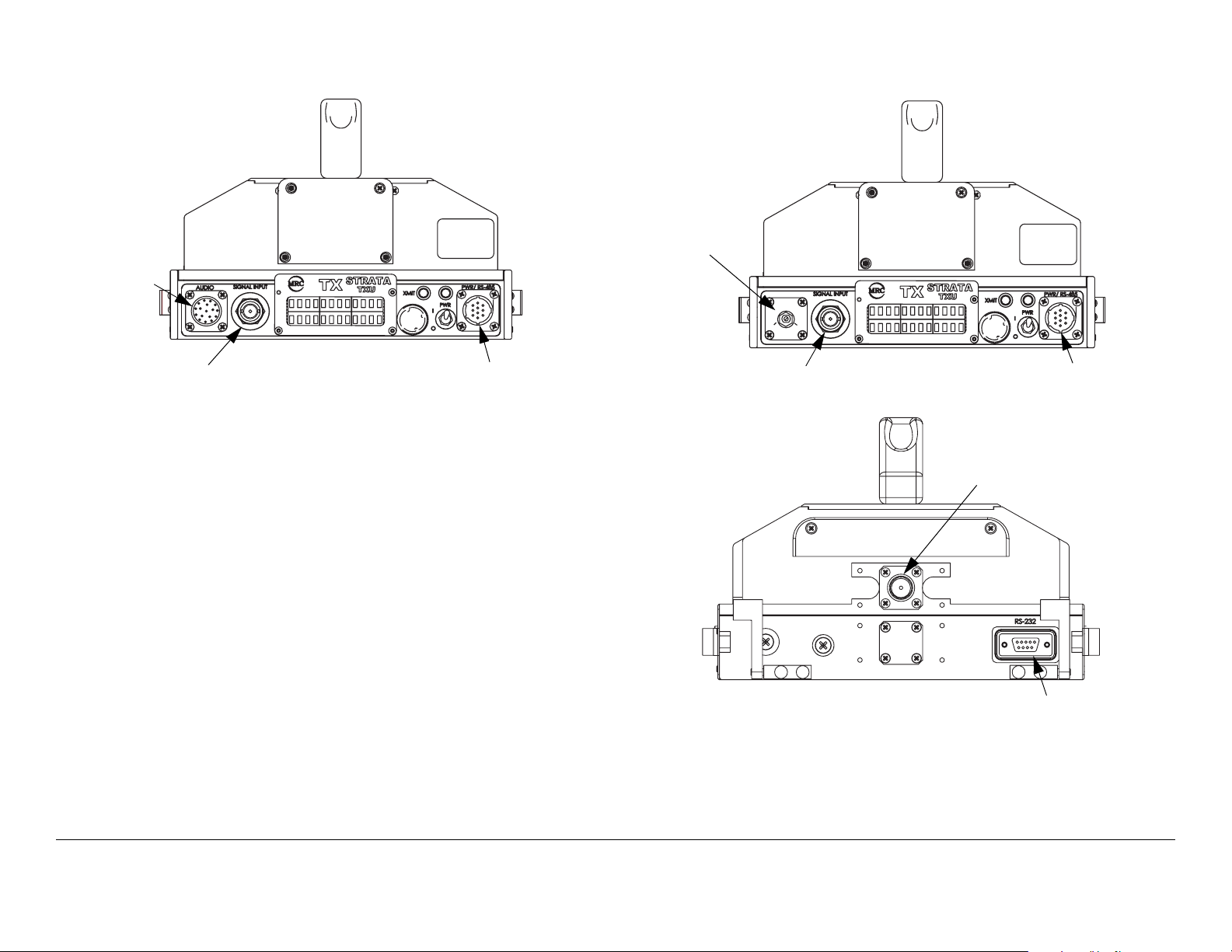
Figure 2-11: Standalone TXU Configuration
Figure 2-12: TXU - TXU with TCU Configuration
DO NOT
EXCEED
36 VOLTS DC
AUDIO
Connector
SIGNAL INPUT
Connector
Front View
PWR/RS-485
Connector
If your TXU was ordered to operate with a TCU, it will not contain
either analog or digital modules and will therefore not contain an
AUDIO connector. The AUDIO connector is replaced by a DC
ON COAX switch. See Figure 2-12.
The DC ON COAX switch allows manual control of DC power to
the TXU from the TCU or from the TCU to the TXU via DC power
superimposed on the coaxial cable connected between the two
units.
The rear of the TXU is identical on both configurations of the
TXU. See Figure 2-12.
DC ON COAX
Switch
SIGNAL INPUT
Connector
DC
ON COAX
OFF ON
Front View
Rear View
DO NOT
EXCEED
36 VOLTS DC
PWR/RS-485
Connector
RF Output
Connector
RS-232
Connector
Product Description 2-10STRATA TX Operator’s Guide/Tech Ref Manual
TCU Several different configurations of the TCU also exist as
the result of technical updates. Configuration differences are
described below.
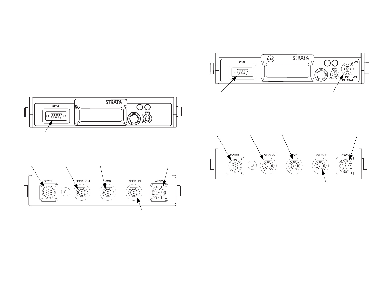
TCU - Older Configuration If your TCU is an older
configuration, the controls and connectors contained on the TCU
are similar to those shown in Figure 2-13. Older configurations
do not contain the front panel DC ON COAX override switch to
provide manual control of DC power to a TXU.
switch is located on the front panel to provide manual control of
DC power to a TXU.
Figure 2-14: TCU - Newer Configuration
TX
TCU
XMIT
Figure 2-13: TCU - Older Configuration
TX
TCU
RS-232
Connector
POWER
Connector
SIGNAL OUT
Connector
Front View
Monitor (MON)
Connector
Rear View
XMIT
SIGNAL IN
Connector
AUDIO
Connector
RS-232
Connector
POWER
Connector
SIGNAL OUT
Connector
Front View
Monitor (MON)
Connector
Rear View
DC ON COAX
Switch
AUDIO
Connector
SIGNAL IN
Connector
TCU - Newer Configuration If your TCU is the newer
configuration, the controls and connectors contained on the TCU
are similar to those shown in Figure 2-14. A DC ON COAX
Product Description 2-11STRATA TX Operator’s Guide/Tech Ref Manual
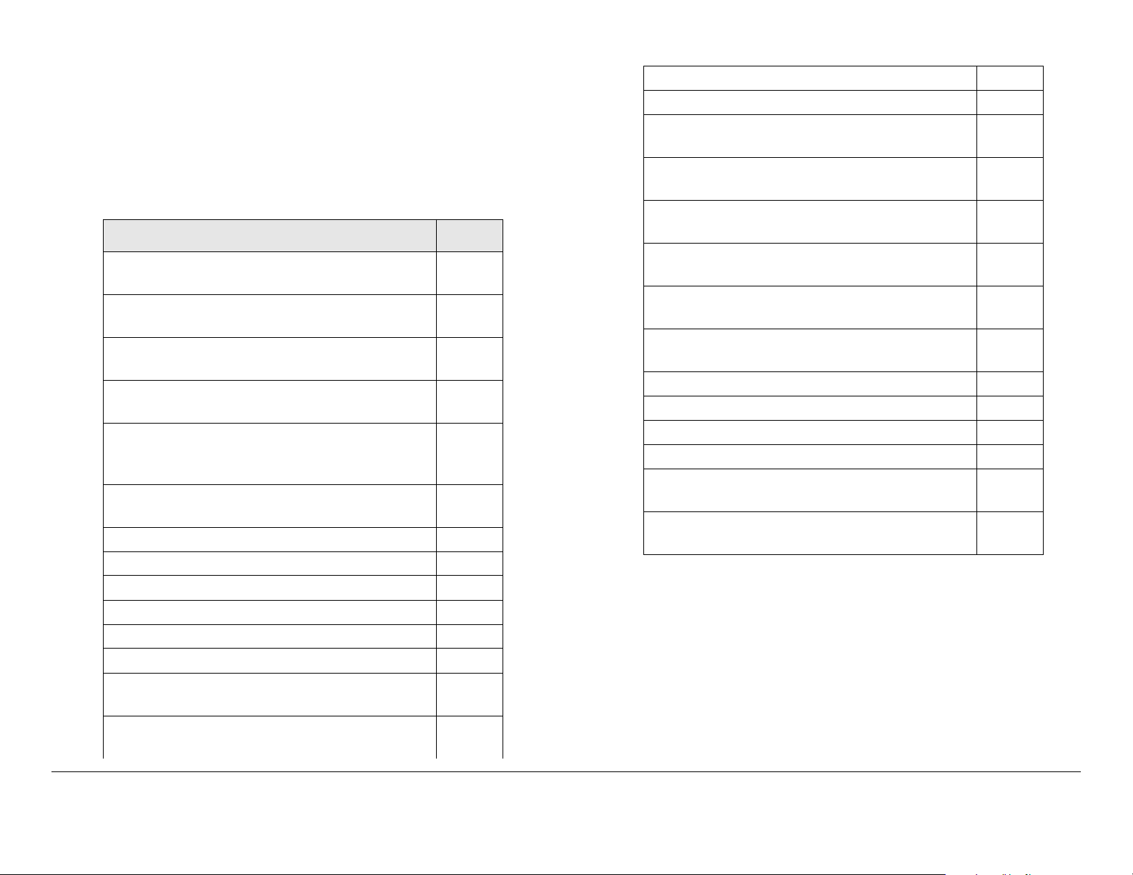
2.5 Typical System Configurations
2.6 For More Information
Typical STRATA TX System configurations are shown in Figure
2-15.
Figure 2-15: STRATA TX System Configurations
Additional detailed technical information about the STRATA TX
System is contained in the STRATA TX Technical Reference
Manual. Specific topics contained in the Technical Reference
Manual are listed below:
Topic Chapter
Changing settings using
the Configurator software
Installation See Chapter 6, “Installation”
Connections to other
equipment
Supported Repairs See Chapter 7, “Repair”
Repair Parts See Chapter 8, “Replacement
Block Diagram See Chapter 9, “Theory of
See Chapter 5, “Advanced
Operation”
See Chapter 6, “Installation”
Parts”
Operation”
Product Description 2-12STRATA TX Operator’s Guide/Tech Ref Manual
3
Routine Operation
3.1 Chapter Overview
This chapter provides basic information that will enable you to
operate your STRATA TX System.
Here are the topics covered:
Topic Page
Overview of Controls, Indicators, and
Connectors
TXU Controls, Indicators, and
Connectors
TCU Controls, Indicators, and
Connectors
ACU Controls, Indicators, and
Connectors
STRATA Standard Remote Control
Panel Controls, Indicators, and
Connectors
STRATA Aircraft Remote Control Panel
Controls, Indicators, and Connectors
Preparing for Operation 3-10
Mobile Installation 3-10
Portable Deployment 3-10
Powering the STRATA TX System 3-12
Single TCU Power Up and Power Down 3-13
3-2
3-2
3-5
3-8
3-9
3-9
Using the STRATA TX Screens 3-20
TXU and/or TCU Monitoring Operations 3-20
Using the Monitor Screens in MPEG
Output Mode
Using the Monitor Screens in Ext IF
Input Mode
Using the Monitor Screens in COFDM IF Mode
Using the Monitor Screens in COFDM
ASI In Mode
Using the Monitor Screens in Analog IF Mode
Using the Monitor Screens in DVB-S
Mode
TXU and/or TCU Control Operations 3-28
Changing a Preset 3-30
Setting a Channel 3-31
Setting Power Output 3-32
Controlling TCU to TXU DC Power on
Coax
Front Panel vs. STRATA TX Configurator
Settings
3-21
3-23
3-24
3-25
3-26
3-27
3-33
3-35
Information on settings made with the STRATA TX Configuration
Utility software can be found in the “Advanced Operation”
Chapter on page 5-1 (part of the STRATA TX System Technical
Reference Manual only).
Single TXU Power up and Power Down 3-14
TXU and TCU Power Up and Power
Down - Co-Located
TXU and TCU Power Up and Power
Down - Separate Locations
3-15
3-17
For a summary of settings that can be made with the TXU and
TCU front panel control switches and which settings are made
using the STRATA TX Configuration Utility, see Section 3.7 on
page 3-35.
Routine Operation 3-1STRATA TX Operator’s Guide/Tech Ref Manual
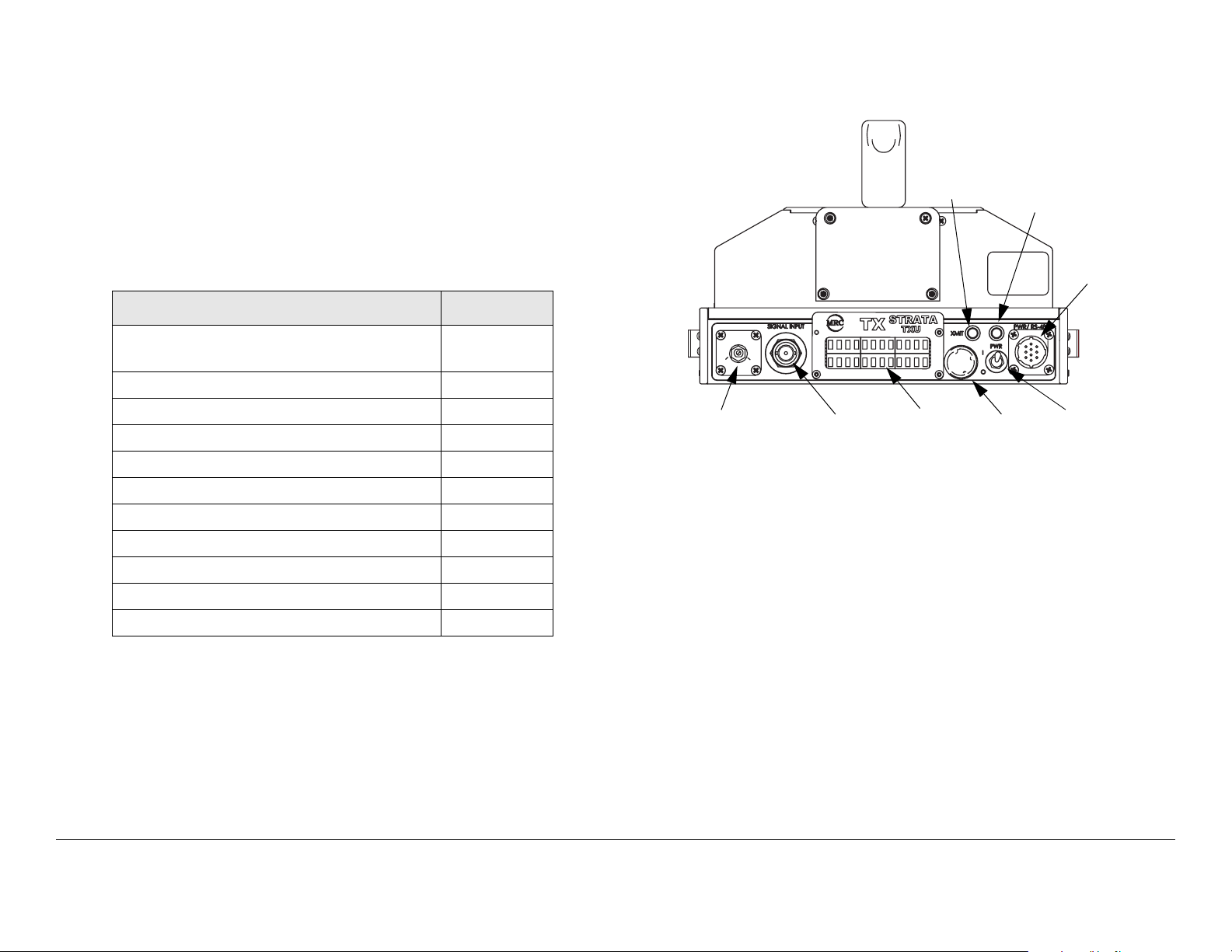
3.2 Overview of Controls, Indicators, and Connectors
Figure 3-1: TXU Controls, Indicators, and Connectors - Front
View
This section describes the controls, indicators, and connectors
used on the STRATA TX System.
3.2.1 TXU Controls, Indicators, and Connectors
Controls, indicators, and connectors contained on the TXU are
identified and described below. Topics covered are as follows:
Topic Page
TXU Front Panel DC ON COAX
Switch
TXU SIGNAL INPUT Connector 3-3
TXU AUDIO Connector 3-3
TXU Alphanumeric Display 3-3
TXU XMIT LED 3-3
TXU Status LED 3-4
TXU PWR/RS-485 Connector 3-4
TXU PWR Switch 3-4
TXU Control Switch 3-4
TXU RF Output Connector 3-5
TXU RS-232 Connector 3-5
Each of these controls, indicators, and connectors are described
in more detail in the following paragraphs.
Controls, indicators, and connectors contained on the TXU front
panel are shown in Figure 3-1. Connectors contained on the
TXU rear panel are shown in Figure 3-2 on page 3-3. For
configuration differences in the TXU, see “TXU and TCU
Configurations” on page 2-9.
3-2
XMIT
DC
ON COAX
OFF ON
DC ON COAX
Switch or AUDIO
Connector
SIGNAL
INPUT
Connector
LED
Alphanumeric
Display
Status
LED
DO NOT
EXCEED
36 VOLTS DC
Control
Switch
PWR/RS-485
Connector
Power
Switch
The TXU is configured using Windows PC-based STRATA TX
Configuration Utility software. For details, see the “Advanced
Operation” Chapter on page 5-1 (part of the STRATA TX System
Technical Reference Manual only).
TXU Front Panel DC ON COAX Switch DC ON COAX
switches are not contained on all configurations of the TXU. For
configuration differences, see “TXU and TCU Configurations”
Chapter on page 2-9.
If your STRATA TX System contains both a TXU and a TCU, the
System allows you to power the TXU using DC power supplied
from the TCU or allows you to power the TCU using DC power
from the TXU. This DC power is superimposed on the coaxial
cable between the TCU and the TXU. This DC power option is
Routine Operation 3-2STRATA TX Operator’s Guide/Tech Ref Manual