

Microwave Radio Communications STAHPU2D User Manual

Strata Transmitter
Operations Guide
Revision 3.0
May 2003
Microwave Radio Communications 101 Billerica Avenue, Bldg 6
(978) 671-5700 N. Billerica, MA 01862-1256
www.mrcbroadcast.com
Strata Operations Guide
1 -
-
Introduction
The Microwave Radio Communications (MRC) Strata system provides a reliable and highly flexible
video microwave transport system. This operations guide provides basic system operations information
and details for hands-on operation of this equipment.
System Description
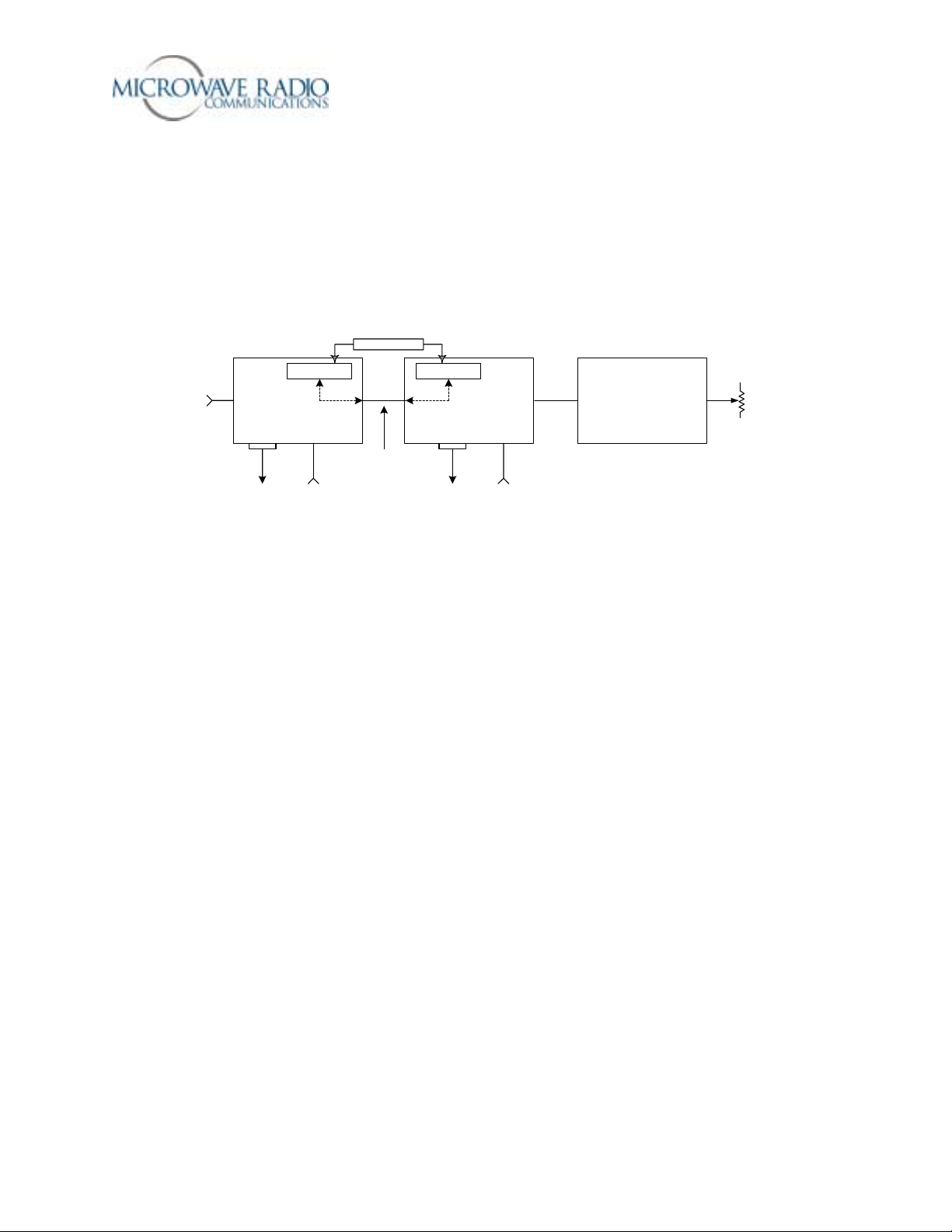
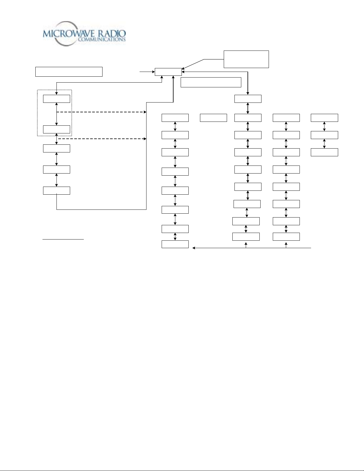
Figure 1 below shows the overall Strata system architecture for a fully equipped system.
1.84 MHz OOK Tone
!
NTSC
!
PAL
!
SDI
ASI
IF
IN
RS-232
!
!
Telemetry Telemetry
TCU TXU HPU
IF or Baseband Si gnal
DC Simplex Powering
12 v to 48 v
DC
RS-232
12 v to 48 v
DC
Figure 1 – Strata Transmitter System Architecture
The primary system features are:
o Lightweight, Modular, Multi- Un it Desig n
o Analog, Digital, or Analog/Digital Switchable
o MPEG Encoding (4:2:0, 4:2:2)
o COFDM Modulation with Selectable Guard Interval
o Digital Modulation for QPSK, 16QAM, and 64QAM
o NTSC or PAL Modulation with Audio (4 mono or 2 stereo)
o Tripod, Half Rack, or Full Rack Mounts
o Front Panel Remote Controlled
o Bands from 2 to 15 GHz
o Wide Choice of Antennas
RF/DC
RF OUT
Dummy Load
Note that the TCU (Transmitter Control Unit) and the TXU (Transmitter Unit) may be operated in a
stand-alone configuration depending on specific video transport applications.
TCU Description
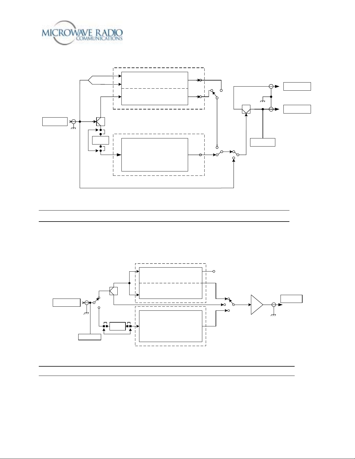
The TCU component can accept a wide variety of signal formats and provide several different output
signal formats. Figure 2 below shows the basic functions of the TCU.
Strata Operations Guide
2 -
-
COAX IN
!
NTSC
!
PAL
!
SDI
!
ASI
!
IF
Filter
SDI
ASI
MPEG CV
Note: Either or both MPEG/COFDM or
FMT boards may be installed
FMT CV
MPEG
COFDM
FMT
ASI
COFDM
70 MHZ
ASI Only Mode
IF CV
70 MHz IF Bypass
Telemetry
MONITOR
COAX OUT
!
COFDM
!
IF CV
!
IF
!
ASI
Figure 2 - Strata TCU Functional Diagram
Note: The TCU may be supplied with or without the MPEG/COFDM or FMT options.
TXU Description
Like the TCU component, the TXU can accept a wide variety of signal formats but includes an RF upconverter for use in transporting signals over a microwave radio link. Figure 3 below shows the basic
functions of the TXU.
ASI MON
ASI COFDM
70 MHZ
70 MHz
IF/RF Up Converter/Amplifier
70 MHZ
SIGNAL IN
!
NTSC
!
PAL
!
SDI
!
ASI
!
IF
Telemetry
CV
SDI/ASI
Filter
SDI MPEG
MPEG CV
MPEG
COFDM
ASI Input
IF
FMT CV
FMT
Figure 3 – Strata TXU Functional Diagram
Note: The TXU may be supplied with or without the MPEG/COFDM or FMT options.
Strata Operations Guide
3 -
-
RF OUT
HPU Description
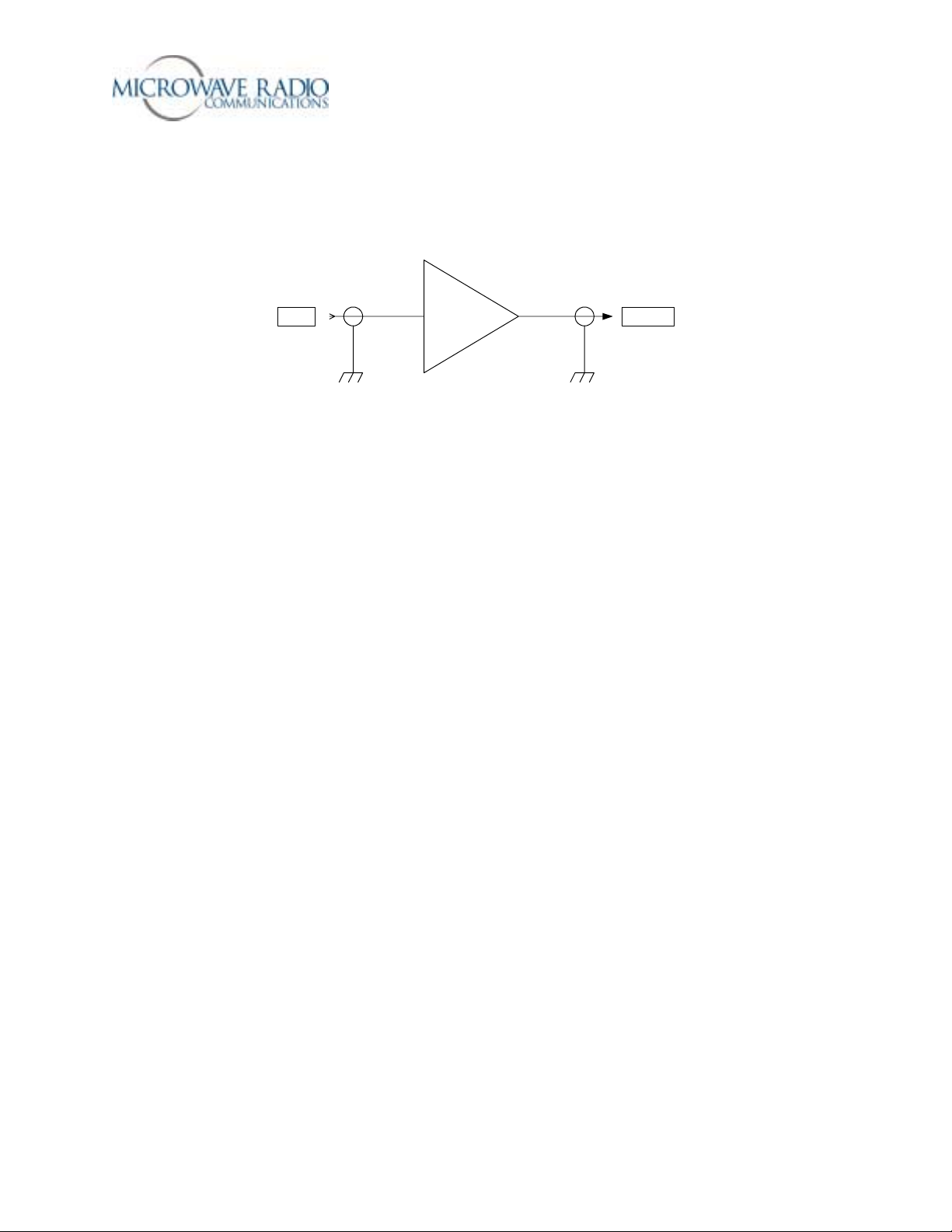
For those applications requiring a higher RF output level, the HPU (High Power Unit) may be used to
boost the signal level to between 2 and 12 watts of microwave output power depending on the modulation
format used. Figure 4 below shows the functional architecture of the HPU device.
HPURF IN RF OUT
Figure 4 – HPU Functional Diagram
Theory of Operation
The Strata TX system is comprised of the following primary components:
• Command and Control Power Supply module
• Combiner Circuit
• MPEG encoder/COFDM modulator module (digital mode)
• FMT (FM Transmitter) (analog mode)
• IF/RF Unit
• HPU (High Power Unit)
Note that some or all of these components may be included in a fully functional Strata TX system
depending on specific customer applications, e.g., switchable analog and digital transmitting system, etc.
Where switchable analog and digital video transmission is required, the Strata TX system installs the
digital and analog video modulator modules and the IF/RF module in separate housings. In this case a
TCU (Transmitter Control Unit) houses the MPEG/COFDM, FMT and Combiner circuits with the IF/RF
unit installed in a separate TXU (Transmitter Unit) housing. This arrangement also allows the video
modulation components (TCU) to be physically separated from the IF/RF up-converter by up to 600 feet.
Command and Control Power Supply
The TCU and TXU Command and Control/Power Supply modules contain external and internal
communications circuitry as well as supplying the necessary system voltages. The power supply portion
accepts a wide range DC input voltage (+10.5 to +48 volts) and distributes appropriate output voltages to
the various circuits. The command and control circuits handle inter-module communications and provide
external RS-232 communications to external peripheral equipment, such as a remote control device
(helicopter operation) or to a PC capable of running Windows based configuration software. An on-board
microprocessor manages the system configuration and operation of all modules to which it is connected,
i.e., MPEG/COFDM, FMT, IF/RF modules, etc. In addition, for those applications that employ both
TCU and TXU housings, a communications link superimposed over the inter-connecting IF coaxial cable
provides communications to all system modules. This ensures the TCU and TXU may control each
other’s operation, i.e., permit switching modes of operation, change system presets, etc.
Strata Operations Guide
4 -
-

Therefore, where both a TCU and TXU are used, total system control may be accomplished using front
panel or remote control from either housing.
MPEG/COFDM Encoder/Modulator
This is the heart of the Strata TX digital mode circuitry. This versatile circuit may be configured to
accept a wide range of digital or analog video and audio signal inputs and provide COFDM (70 MHz), IF
(70 MHz) or ASI video signal outputs. When installed in a TCU housing, the various signal inputs and
outputs are connected through the TCU Combiner circuit where the various signal inputs and outputs are
switched using software controls.
FMT
The optional FMT module accepts standard NTSC or PAL analog video and audio signals and FM
modulates these signals on a 70 MHz carrier. Using the MRC supplied configuration software, four
different audio sub-carrier frequencies may be defined in which up to four standard audio signals may be
transported with the associated video signal. Note that audio deviation levels are software controlled and
must be provisioned at the MRC factory when ordering this option.
TCU
The TCU may house either or both digital and analog video modulation modules. Where a customer
application might initially employ only analog video transmission but anticipates migrating to dual
(switchable) analog and digital operation, the TCU may be upgraded to add the MPEG/COFDM module
to provide this additional capability. Where only digital or analog video transmission is desired, the
MPEG/COFDM or FMT modules may be installed in a TXU housing thereby eliminating the need for a
TCU. Note that the Strata TX design does not permit splitting digital and analog video modulator
modules between a TCU and TXU. A TCU configuration may also include a “stand-alone” option where
either or both MPEG/COFDM and FMT modules may be used independent of the TXU. This
arrangement permits using a TCU equipped with analog and/or digital video modulation modules for a
variety of signal input and signal output configurations, including a digital option using NTSC or PAL
composite video input and ASI (digital) signal output.
TXU
The TXU always houses the IF/RF module, which accepts either a 70 MHz COFDM, FMT IF, or external
70 MHz input signal and up-converts these signals to the appropriate RF band. The RF frequency
synthesizer circuit included in the IF/RF unit, along with the command and control module, provide the
means to channelize RF video and audio signals in the 2 GHz RF band. Standard U.S. FCC band plans,
as well as customer created channel plans, may be accommodated using the Strata TX Windows based
configuration software. As noted above, the TXU may also include either an MPEG/COFDM or FMT
module (but not both) in which case the TXU serves as a stand-alone digital or analog video microwave
transmission system.
HPU
The optional HPU (High Power Unit) is designed to work with a companion TXU in which case RF
output signals from the TXU are connected to the RF input jack of the HPU. In the case of analog
microwave transmission, the RF output of the TXU is amplified operating the HPU RF amplifier in the
non-linear region (saturated) providing RF output levels at the 12 watt level (+41 dBm). In the case
where COFDM RF signals are used, software controlled back-off attenuation is applied to operate the
HPU RF amplifier in the linear region.
Strata Operations Guide
5 -
-

These back-off levels are carefully measured and configured as part of MRC factory adjustment
procedures and ensure digital mode RF output signals provide optimum performance. Therefore,
depending on what digital mode modulation format is selected, i.e., QPSK, 16 QAM or 64 QAM, or if an
HPU is used, previously configured transmitter back-off levels are applied to ensure the Strata TX RF
output signals operate with minimum Inter-Modulation Distortion (IMD). These carefully measured and
configured transmitter back-off levels are stored in the TXU IF/RF unit and are applied depending on
which particular operating mode is selected. Typical digital mode RF levels vary from 5 watts to 2 watts
output depending mostly on the modulation format selected.
Overall Operational Details
The following details apply when operating the Strata system using either the TCU or TXU front panel
controls:
1. When companion TXU or TCU devices are inter-connecte d via coaxia l cab les, an inter-unit telemetry
link is established. This feature allows overall system operation and configuring to be accomplished
from either the TCU or TXU devices if both are used. For example, the microwave transmitter may
be keyed ON or OFF from either device.
2. A configuration software tool (Strata TX Configurator) may be used to review and modify certain
system configuration options as described in this document.
Special Note: All radio systems leaving the MRC factory are adjusted per standard industry (default)
settings, i.e., video and audio levels versus FM deviation (analog), as well as digital and analog IF and RF
levels, etc. In addition, transmitter back-off (IMD) and analog audio levels are carefully adjusted using
special software tools. Many of these settings are software controlled and cannot be adjusted in the field.
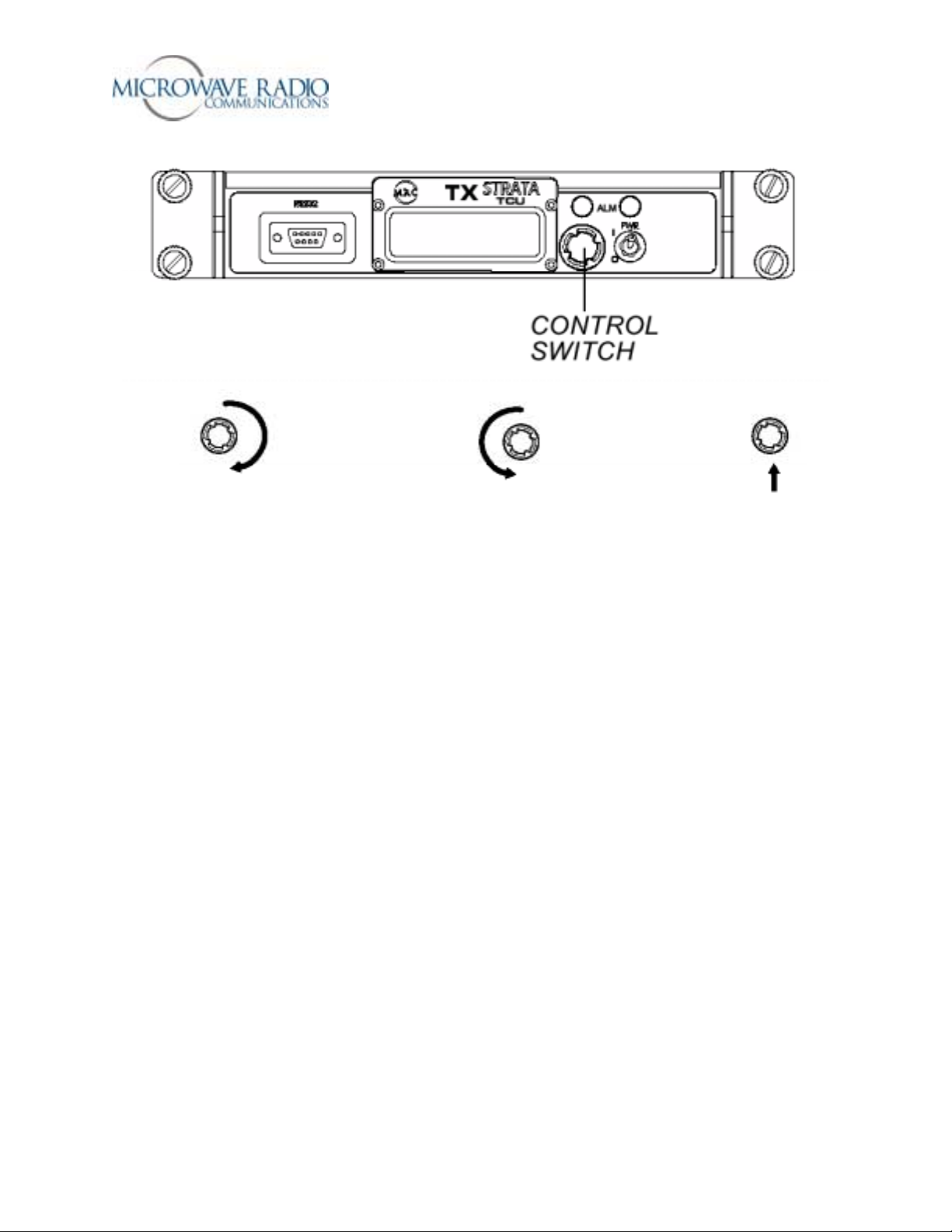
How to View Configuration Parameters and Control the TCU/TXU Units from the Front Panel
Figure 5 below shows the basic TCU/TXU control functionality using the front panel control switch:
Strata Operations Guide
6 -
-
Display Monitor Screen
Push to Select
Rotate to Change
Push to Select
Figure 5 – Front Panel Switch Control
TCU/TXU Front Panel Control Settings
The front panel control switch is used to select a limited number of front panel control functions. Rotating
the switch counterclockwise allows access to mode selection choices, while rotating the switch clockwise
allows access to monitoring the current mode of operation. The plunger action of the switch is used to
select the appropriate mode of operation. The TXU and associated HPU (High Power Unit), if equipped,
is keyed ON or OFF by compressing and holding the front panel control switch for one second from any
menu page. The Strata TX system is transmitting when the front panel blue “XMIT” LED is illuminated.
When the menu display is inactive for more than 7 seconds, the display will revert back to the main menu.
The following front panel control selections are available:
• Set RF Channel
• Change Preset – Presets #1 to #9
• Set Power Out – HPU attenuation control
• HPU Present
• 75 Ohm Coax DC Power ON/OFF – Coaxial cable DC power ON/OFF control
Note: The remainder of front panel selec ti ons allow monitoring previously configured parameters and
system status, including alarm indications, power output, etc.
Details related to the use of Strata TX front panel controls are found on the following page.
Strata Operations Guide
7 -
-

RF Channel Select
The radio is pre-programmed with a number of RF channel frequencies associated with up to 9 preset
configurations. Use this feature to monitor the currently configured RF frequencies. Note: If these
frequencies are known as part of a customer order, they may be factory set to customer requirements or
added or modified per customer request.
Select Preset Setting
Used to select a pre-configured configuration. Up to 9 different configurations may be stored and
configured in conjunction with the Strata TX Configurator utility.
Set Attenuation Value (Transmitter Back Off Level)
Used to set the transmitter output power (and linear operating point) of the radio system. Adjustable from
0 to 31 dB in 1 dB increments. Push to select.
Note: Maximum power output occurs with 0 dB of attenuation applied.
75 Ohm Coax ON/OFF
Used to activate or de-activate DC powering a TCU or TXU through the inter-connecting IF coaxial
cable.
Front Panel Transmitte r Po we r Mon ito rin g
The current TX output power reading available on the front panel may be used as a general reference and
is accurate to within +/- 1 dB.
HPU Present
Identifies and configures use of the HPU option connected to the TXU device.
Please see the front panel menu guide on the following page for details related to front panel operation.
Strata Operations Guide
8 -
-
A
y
Strata Front Panel Operation
Control Me nu Access
Scroll Menu Button to Left - Push to Select
( Default to Main Menu after 7 seconds of inactivity)
Set Channel
Ch 9
*
Change Preset
Preset #1
Set Power Out
Atten 0 dB
HPU Coax
HPU Present
75 Ohm Coax
Power On
Note:
*
For helicopter applications the c hannel select will be included with the
preset conditions.
1) Push to activate
2) Rotate to change
3) Push to select
back to main
menu after set
1) Push to activate
2) Rotate to change
3) Push to se lect - up to 9 pre s ets
back to main
menu after set
1) Push to activate
2) Rotate to change
3) Push to select - 0 -31 dB values
Caution:
Enables HPU opera tio n and DC
voltage on coax (from th e TXU) when
transmitting - push to activate or deactivate
HPU.
Caution:
This function enables DC voltage t o
flow between the TC U and TXU on the IF
coax cable - push to turn On and Off.
Presetable Parameters
Video Input Chroma
Delay Mode FEC
ASI Output COFDM Bandwidth
BISS - On/Off Guard Interval
BISS Key Modulation
Audio Input Conditions A & B VBI - On/Off
Audio Mode Con d i tio ns
Color Bars/Pilot Condition - Service Name/Network Name
IF Mode of Operat ion
Analog Audi o S ubcarrier On/Off
nalog Audio Subcarrier Frequenc
@ DC Power Up
Preset #1
HPU In C9
Control Me nu Access:
Scroll Menu Button to Right to Monitor
RF Configuration status
(Pout level - TXU only)
Mode
MPEG Output
NTSC
Vid In 4:2:0
Video Delay
Normal
ASI Bit Rate
10.2000 Mbs
MPEG Audio A
Analog Stereo
MPEG Audio B
Analog Stereo
Color Bar Off
Error Page
Note:
Last operational state will be saved on power down.
Mode
Ext IF Input
COFDM Config Status
with bit rate flashing
Video Input Status &
MPEG Chroma
Video Input error flashes w/ no video
Video delay
MPEG Audio A
Config Sta tus
MPEG Audio B
Config Sta tus
Color Bar & Pilot
Status In dicator
Strata Front Panel Guide Diagram
Turn Transmitter ON from
any menu screen -
menu button in for 1 second
Blue TX light ON
2475.500 MHz
FEC 1/2 GI 1/8
Video In 4:2:0
MPEG Audio A
Analog Stereo
MPEG Audio B
Analog Stereo
Color Bar Off
Error Page Error Page
HPU Off C9
Mode
COFDM - IF
QPSK 8MHz
NTSC
Video Delay
Normal
Pilot Off
Push
Caution:
DC ouput voltage from TXU is slaved
to the blue light condition shown as the "HPU
In" condition whe n transmitting.
Monitor Menus
A Function of IF Mode Selection
Mode
Analog - IF
Audio #1 On
Pre 4.83MHz
Audio #2 On
Flat 6.20 MHz
Audio #3 Off
Pre 6.80MHz
Audio #4 Off
Pre 7.20MHz
Vid Dev 4MHz
Pre 525L In
Pilot Off
Mode
COFDM ASI In
QPSK 8MHz
FEC 1/2 GI 1/8
Color Bar Off
Pilot Off
Refer to MID errors
Strata Operations Guide
9 -
-
Supported Strata TX System Configuration Options
The following information may be used to identify which Strata TX system options may be used for
specific customer applications.
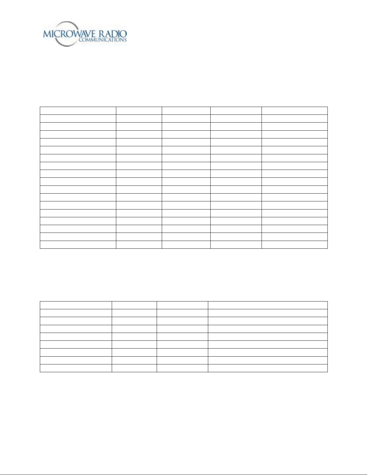
TCU Supported Signal Options
Hardware Option Signal Input Signal Output Monitor Out Notes
* MPEG/COFDM Only NTSC/PAL ASI Various formats
* MPEG/COFDM Only SDI (525/625) ASI Various formats
* MPEG/COFDM Only NTSC/PAL COFDM - IF COFDM Various formats
* MPEG/COFDM Only SDI (525/625) COFDM - IF COFDM Various formats
* MPEG/COFDM Only ASI COFDM - IF COFDM Various formats
* MPEG/COFDM Only IF IF IF IF Bypass Mode
FMT Only NTSC/PAL IF CV IF CV NTSC/PAL CV IF
FMT Only IF IF IF IF Bypass Mode
* MPEG/COFDM + FMT NTSC/PAL ASI Various formats
* MPEG/COFDM + FMT SDI (525/625) ASI Various formats
* MPEG/COFDM + FMT NTSC/PAL COFDM - IF COFDM Various formats
* MPEG/COFDM + FMT NTSC/PAL IF CV IF CV NTSC/PAL IF
* MPEG/COFDM + FMT SDI (525/625) COFDM - IF COFDM Various formats
* MPEG/COFDM + FMT ASI COFDM - IF ASI or COFDM Various formats
* MPEG/COFDM + FMT IF IF IF IF Bypass Mode
Notes:
* = ASI output possible when TCU used in stand-alone (MPEG only) mode
TXU Supported Signal Options
Hardware Option Signal Input Signal Output Notes
MPEG/COFDM Option NTSC/PAL COFDM - RF Various formats
MPEG/COFDM Option SDI (525/625) COFDM - RF Various formats
MPEG/COFDM Option ASI COFDM - RF Various formats
MPEG/COFDM Option IF RF Up-converted Channelized RF signal
FMT Option NTSC/PAL CV - RF NTSC/PAL CV Channelized RF
FMT Option IF RF Up-converted Channelized RF signal
No options installed IF RF Up-converted Channelized RF signal
Note: TXU supports either MPEG/COFDM option or FMT option, but not both.
Strata Operations Guide
10 -
-

Configuring the Radio System using the TCU/TXU Serial Port and the
“Strata TX Configu r ator” Software Ut ility
Basic Strata TX Configuration Details
The following basic system configuration settings may be administered using the Strata TX Configurator
software utility.
• COFDM IF Mode – 70 MHz COFDM IF output from the internal COFDM/MPEG board supplied to
output and monitor ports (to TXU if present).
• IF Input – 70 MHz IF input signal from input connector routed through TCU to TXU (if present).
• ASI Input – Bypasses internal MPEG encoder and routes an externally supplied ASI stream to the
monitor and output connectors (to TXU if present).
• MPEG ASI Output – supplies a DVB ASI transport stream to the signal output connector and the
monitor output connector. Note: This mode is only accessed when the TCU is operated in a stand-
alone configuration.
• Analog Audio/Video – Routes 70 MHz FM output to TXU (if present). This mode is only supported
with the FMT option installed.
• DVB-S – This operational mode uses a single carrier modulator scheme and supplies a 70 MHz IF
output to the signal output connector and the monitor output connector, only operational for QPSK
and 16 QAM. Note: This mode is currently not supported in the current software release.
• RF Frequency
Used to select an RF frequency from 1.99 GHz – 2.50 GHz (up to 5 decimal places).
• Modulation Type
Used to select each digital modulation mode for COFDM operation and DVB-S mode (when
applicable) – QPSK, 16 QAM, 64 QAM. Note: 64 QAM modulation may not be used in the DVB-S
mode of operation.
• FEC Type
Used to select each FEC (Forward Error Correction) scheme to be used – (1/2, 2/3, 3/4, 5/6, 7/8).
• COFDM Guard Interval
Used to select the individual Guard Interval for COFDM operation only – 1/32, 1/16, 1/8, 1/4.
• COFDM Bandwidth
Used to select COFDM bandwidth operation – 6 MHz, 7 MHz, or 8 MHz.
• Video Input
Used to select the necessary video input for the MPEG encoder from the following selections:
NTSC composite video, PAL composite video, SDI – 525 line, SDI – 625 line.
• Chroma
Used to select MPEG chroma profile – 4:2:0 (420 profile @ main level), 4:2:2 (422 profile @ main
level).
• Color bars
Used to turn the internal color bars generator ON, OFF or place in AUTO mode – (used in IF digital
modes only). Color bars will display a user programmed Service Name parameter if applied. Video
input is bypassed when ON. Auto mode will insert color bars when no video input is detected
Strata Operations Guide
11 -
-
 Loading...