

Microwave Radio Communications PTX270AD User Manual
PTX-PRO
Transmitter
User and Technical
Manual Part No. 400611-1 Rev. C July 2011

Copyright © 2011
Part number 400611-1
Printed in U.S.A.
Authorized EU representative: Vislink PLC
Quality Certification Vislink is certified to ISO 9001:2008.
The Vislink trademark and other trademarks are registered trademarks in the United States and/or other countries.
Microsoft®, Windows®, and Internet Explorer® are registered trademarks of Microsoft Corporation in the United States
and/or other countries.
Proprietary Material The information and design contained within this manual was originated by and is the property
of Vislink. Vislink reserves all patent proprietary design, manufacturing, reproduction use, and sales rights thereto, and
to any articles disclosed therein, except to the extent rights are expressly granted to others. The foregoing does not
apply to vendor proprietary parts. Vislink has made every effort to ensure the accuracy of the material contained in this
manual at the time of printing. As specifications, equipment, and this manual are subject to change without notice,
Vislink assumes no responsibility or liability whatsoever for any errors or inaccuracies that may appear in this manual
or for any decisions based on its use. This manual is supplied for information purposes only and should not be
construed as a commitment by Vislink. The information in this manual remains the property of Vislink and may not be
used, disclosed, or reproduced in any form whatsoever, without the prior written consent of Vislink. Vislink reserves the
right to make changes to equipment and specifications of the product described in this manual at any time without
notice and without obligation to notify any person of such changes.
General Safety Information The following safety requirements, as well as local site requirements and regulations,
must be observed by personnel operating and maintaining the equipment covered by this manual to ensure awareness
of potential hazards. This equipment has been tested and found to comply with the limits for a Class A digital device,
pursuant to Part 15 of the FCC Rules. These limits are designed to provide reasonable protection against harmful
interference when the equipment is operated in a commercial environment. This equipment generates, uses, and can
radiate radio frequency energy. If not installed and used in accordance with the instruction manual, it may cause
harmful interference to radio communications. Operation of this equipment in a residential area is likely to cause
harmful interference in which case the user will be required to correct the interference at his own expense.
About this Manual This manual is intended for use by qualified operators, installers, and service personnel. Users of
this manual should already be familiar with basic concepts of radio, video, and audio. For information about terms in
this manual, see Glossary of Terms and Abbreviations (Part No. 400576-1). Pay special attention to Notes, Cautions,
and Warnings.
Read Notes for important information to assist you in using and maintaining the equipment.
Follow CAUTIONS to prevent damage to the equipment.
Follow WARNINGS to prevent personal injury or death.
Symbols The following symbols may be on the equipment or in this manual:
WARNING: General Warning.
Risk of Danger.
WARNING: Risk of Electric Shock. Earth Ground: Identifies the earth ground
CAUTION: Electrostatic Discharge.
Possible Damage to Equipment. Fuse (either icon):
Frame or Chassis Ground: Identifies the frame
or chassis terminal.
terminal.
Identifies fuses or their location.
Protective Earth Ground: Identifies any
terminal intended for connection to an
external conductor for protection against electric shock in case of a fault, or the
terminal on a protective earth electrode.
101 Billerica Avenue - Bldg. 6
North Billerica, MA 01862-1256 USA
TEL: 800.490.5700 or +1.978.671.5700
Waste Electrical and Electronic Equipment
(WEEE): The product must not be disposed of
with other waste. You must dispose of the
waste equipment by handing it over to a designated collection point for recycling.

Contents
1 About the PTX-PRO
1.1 Front Panel Controls, Indicators, and Connectors - - - - - - - - - - - - - - - - - - - 1-2
1.2 Rear Panel Connectors and Fuses - - - - - - - - - - - - - - - - - - - - - - - - - - - - - - 1-3
1.3 Related Documents- - - - - - - - - - - - - - - - - - - - - - - - - - - - - - - - - - - - - - - - - 1-4
1.4 Channel Plans (2, 7, and 13) - - - - - - - - - - - - - - - - - - - - - - - - - - - - - - - - - - 1-5
1.4.1 The 2 GHz Channel Plan - - - - - - - - - - - - - - - - - - - - - - - - - - - - - - - - - 1-5
1.4.2 The 7 GHz Channel Plan - - - - - - - - - - - - - - - - - - - - - - - - - - - - - - - - - 1-5
1.4.3 The 13 GHz Channel Plan - - - - - - - - - - - - - - - - - - - - - - - - - - - - - - - - 1-6
2 Installing the PTX-PRO
2.1 Unpacking the PTX-PRO - - - - - - - - - - - - - - - - - - - - - - - - - - - - - - - - - - - - - 2-1
2.2 Preparing to Install the PTX-PRO - - - - - - - - - - - - - - - - - - - - - - - - - - - - - - - 2-1
2.2.1 Operating in Safety - - - - - - - - - - - - - - - - - - - - - - - - - - - - - - - - - - - - - 2-1
2.2.2 Powering and Grounding the PTX-PRO- - - - - - - - - - - - - - - - - - - - - - - 2-4
2.3 Mounting on an MRC Tripod - - - - - - - - - - - - - - - - - - - - - - - - - - - - - - - - - - 2-5
2.4 Mounting on a Non-MRC Tripod - - - - - - - - - - - - - - - - - - - - - - - - - - - - - - - - 2-5
2.5 Installing Configurator Software - - - - - - - - - - - - - - - - - - - - - - - - - - - - - - - - 2-8
3 Operating the PTX-PRO
3.1 Powering Up- - - - - - - - - - - - - - - - - - - - - - - - - - - - - - - - - - - - - - - - - - - - - - 3-1
3.2 Using the Display Screen- - - - - - - - - - - - - - - - - - - - - - - - - - - - - - - - - - - - - 3-1
3.3 Monitoring PTX-PRO Operations - - - - - - - - - - - - - - - - - - - - - - - - - - - - - - - 3-2
3.4 Configuring the PTX-PRO Manually - - - - - - - - - - - - - - - - - - - - - - - - - - - - - 3-3
3.5 Configuring the PTX-PRO With a PC - - - - - - - - - - - - - - - - - - - - - - - - - - - - 3-4
3.5.1 Connecting the PTX-PRO to the MRC Radio Configurator - - - - - - - - - 3-4
3.5.2 Loading Parameters from the Radio or a File - - - - - - - - - - - - - - - - - - - 3-5
3.5.3 Saving Parameters to the Radio or a File- - - - - - - - - - - - - - - - - - - - - - 3-5
3.5.4 Changing the Name of a Preset - - - - - - - - - - - - - - - - - - - - - - - - - - - - 3-5
3.5.5 Modifying Preset Parameters - - - - - - - - - - - - - - - - - - - - - - - - - - - - - - 3-6
4 Troubleshooting
4.1 Getting Support for Your PTX-PRO - - - - - - - - - - - - - - - - - - - - - - - - - - - - - 4-1
4.1.1 Replacement Parts - - - - - - - - - - - - - - - - - - - - - - - - - - - - - - - - - - - - - 4-1
4.1.2 Supported Repairs - - - - - - - - - - - - - - - - - - - - - - - - - - - - - - - - - - - - - 4-2
4.2 Addressing General Problems - - - - - - - - - - - - - - - - - - - - - - - - - - - - - - - - - 4-2
4.3 Addressing Display Error Messages - - - - - - - - - - - - - - - - - - - - - - - - - - - - - 4-3
4.4 Addressing Video Problems - - - - - - - - - - - - - - - - - - - - - - - - - - - - - - - - - - - 4-3
4.5 Addressing Error Codes - - - - - - - - - - - - - - - - - - - - - - - - - - - - - - - - - - - - - 4-4
4.6 Addressing Configurator Problems - - - - - - - - - - - - - - - - - - - - - - - - - - - - - - 4-5
Contents-1PTX-PRO User and Technical Manual

A PTX-PRO Specifications
A.1 PTX-PRO Physical Specifications - - - - - - - - - - - - - - - - - - - - - - - - - - - - - - A-1
A.2 Power Connections- - - - - - - - - - - - - - - - - - - - - - - - - - - - - - - - - - - - - - - - - A-1
A.2.1 Power Supply and Distribution - - - - - - - - - - - - - - - - - - - - - - - - - - - - - A-1
A.3 Audio Connections - - - - - - - - - - - - - - - - - - - - - - - - - - - - - - - - - - - - - - - - - A-3
A.3.1 Front Panel Audio Connections - - - - - - - - - - - - - - - - - - - - - - - - - - - - A-3
A.3.2 Rear Panel Audio Connections- - - - - - - - - - - - - - - - - - - - - - - - - - - - - A-4
A.3.3 MPEG Audio input - - - - - - - - - - - - - - - - - - - - - - - - - - - - - - - - - - - - - A-5
A.3.4 AES/EBU Audio input - - - - - - - - - - - - - - - - - - - - - - - - - - - - - - - - - - - A-5
A.4 Video Connections - - - - - - - - - - - - - - - - - - - - - - - - - - - - - - - - - - - - - - - - - A-5
A.5 Data Connections - - - - - - - - - - - - - - - - - - - - - - - - - - - - - - - - - - - - - - - - - - A-5
A.5.1 Wayside Data - - - - - - - - - - - - - - - - - - - - - - - - - - - - - - - - - - - - - - - - - A-7
A.5.2 Networking - - - - - - - - - - - - - - - - - - - - - - - - - - - - - - - - - - - - - - - - - - - A-7
Index
Contents-2
PTX-PRO User and Technical Manual
1
About the PTX-PRO
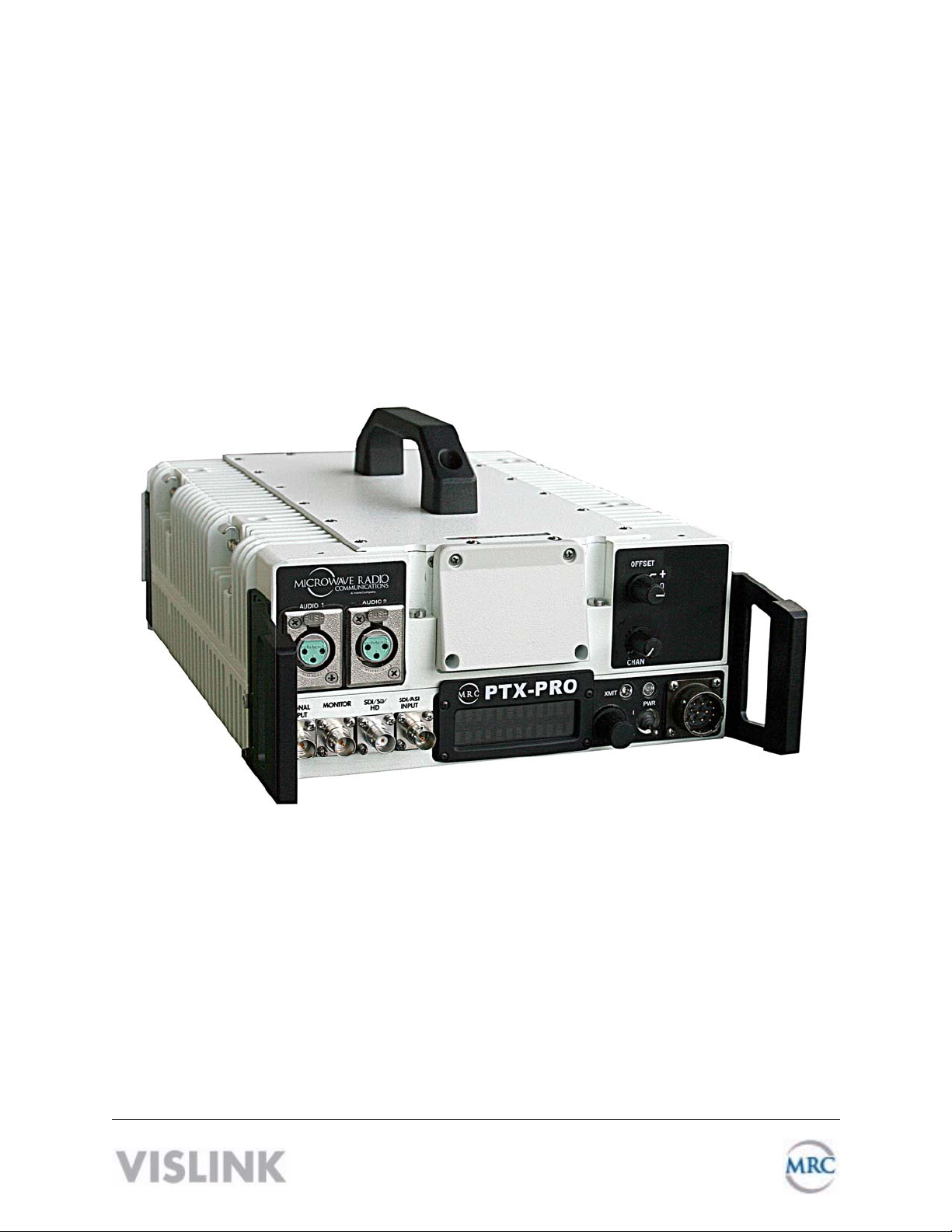
The PTX-PRO (see figure) is a versatile portable transmitter supporting many options and
configurations. The transmitter supports digital, or digital and analog modulation accepting a
wide range of inputs, such as composite video/audio, HD/SD SDI, ASI or external 70 MHz IF
signal. The PTX-PRO is available for single band operation at 2, 7, or 13 GHz, or for dual band
operation at 2 and 7 GHz.
The PTX-PRO provides for
video microwave
communications and is a highly
reliable, flexible, and compact
portable microwave transmitter
for either tripod or mobile
applications.
The PTX-PRO is ideal for
portable Electronic News
Gathering (ENG), Digital Video
Broadcasting (DVB), mobile
communications, wireless airborne networks, and Outside Broadcast (OB) systems.
The RF frequency synthesizer circuit included in the IF/RF module, in conjunction with the
command and control power supply module, creates RF video and audio signal channels in the
various standard FCC band plans. You can use standard U.S. FCC band plans or create
custom channel plans using the MRC Radio Configurator software on a PC.
The PTX-PRO includes MPEG/CODFM modules that can serve as a stand-alone digital video
and audio encoder. Additionally, both NTSC or PAL analog video are available.
The PTX-PRO is fully compatible with the MRC family of transmit antennas, including the
following:
• MRC MegaHorn Compact Horn antennas
• MRC 2, 3, and 4 ft. parabolic antennas
The PTX-PRO contains a universal AC/DC power supply and can operate on either external AC
or DC power sources. The PTX-PRO has the following power requirements, depending upon
the power option utilized.
Supply Voltage: +11.0—+36.0 Volts DC
90—264 VAC, 50/60 Hz
Power Consumption: 50 watts nominal
About the PTX-PRO 1-1PTX-PRO User and Technical Manual
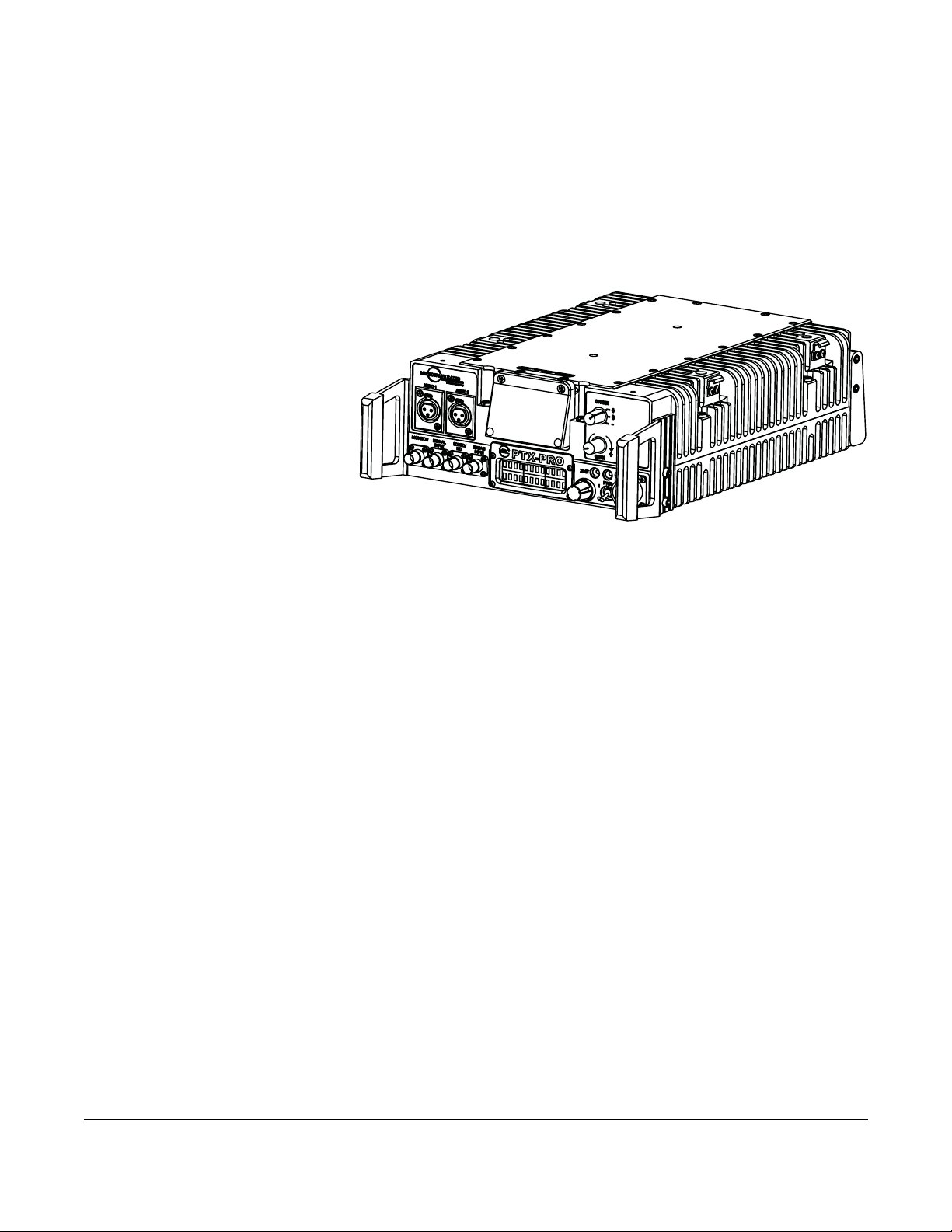
1.1 Front Panel Controls, Indicators, and Connectors
Each of these controls, indicators, and connectors are described in more detail in the following
paragraphs. Controls, indicators, and connectors contained on the PTX-PRO front panel are
shown in the following figure. A dual band switch is added to the indicated position if you order
the 2 and 7 GHz dual band option.
Dual Band
Switch (dual
band models only)
XMIT
LED
PWR
LED
AC/DC
Power
Connector
SIGNAL
INPUT
Connecto
AUDIO 1
Connector
AUDIO 2
Connector
Alphanumeric
Display
CHAN
Switch
OFFSET
Switch
MONITOR
Connector
AUDIO 1 and AUDIO 2 XLR Connectors Provides balanced audio inputs for audio
subcarriers 1 and 2 or MPEG L1/R1.
Alphanumeric Screen Displays 2 lines of 12 alphanumeric characters in conjunction with the
control switch to monitor system status and to control system settings.
CHAN Switch Lets you choose the operating channel: 2 GHz (1—10), 7 GHz (1—14) and 13
GHz (1—22). The selected channel displays on the Main screen. See Section 1.4, Channel
Plans (2, 7, and 13) on page 1-5 for information about channel plans.
OFFSET Switch Lets you set the channel offset (+, 0, or –) channel offset. Note: For the 13
GHz plan, you cannot select offset – (minus) for Channel 1 and you cannot select offset + (plus)
for Channel 22.
Dual Band Switch On PRX-PRO dual band models only: lets you set the channel to 2 GHz or
7 GHz.
XMIT LED Displays Status as follows when the control switch is pushed:
Blue—Transmit mode.
None—Standby mode.
SDI/SD/HD
Connector
ASI INPUT
Connector
Control
Switch
PWR
Switch
PWR LED Displays status as follows:
None—No power to the unit.
Green—Operational and no errors.
Amber—Abnormal condition that might impair performance.
Red—Failure or error that prevents normal operation.
1-2 About the PTX-PRO PTX-PRO User and Technical Manual
WARNING
AC/DC Power Connector Provides external AC or DC power sources.
PWR Switch Controls application of AC or DC power to the PTX-PRO.
Control Switch Turns clockwise to access status monitoring; see Section 3.3, Monitoring PTX-
PRO Operations on page 3-2. Turns counterclockwise to set device parameters; see
Section 3.4, Configuring the PTX-PRO Manually on page 3-3. Press the control switch to set a
parameter or lock a display (while it continues to update); press it again to unlock it.
ASI INPUT 75 Ohm BNC Female Connector Provides ASI inputs to the unit.
SDI/HD/SD 75 Ohm BNC Female Connector Provides the HD/SD/SDI data stream input to the
unit.
MONITOR 75 Ohm BNC Female Connector Provides 70 MHz output for external signal
monitoring.
SIGNAL INPUT 75 Ohm BNC Female Connector Provides the input connection for 70 MHz IF,
composite video (CV) (PAL or NTSC).
A Major Alarm (red PWR LED) may also indicate a potential safety
hazard.
Shut down the PTX-PRO transmitter and disconnect power.
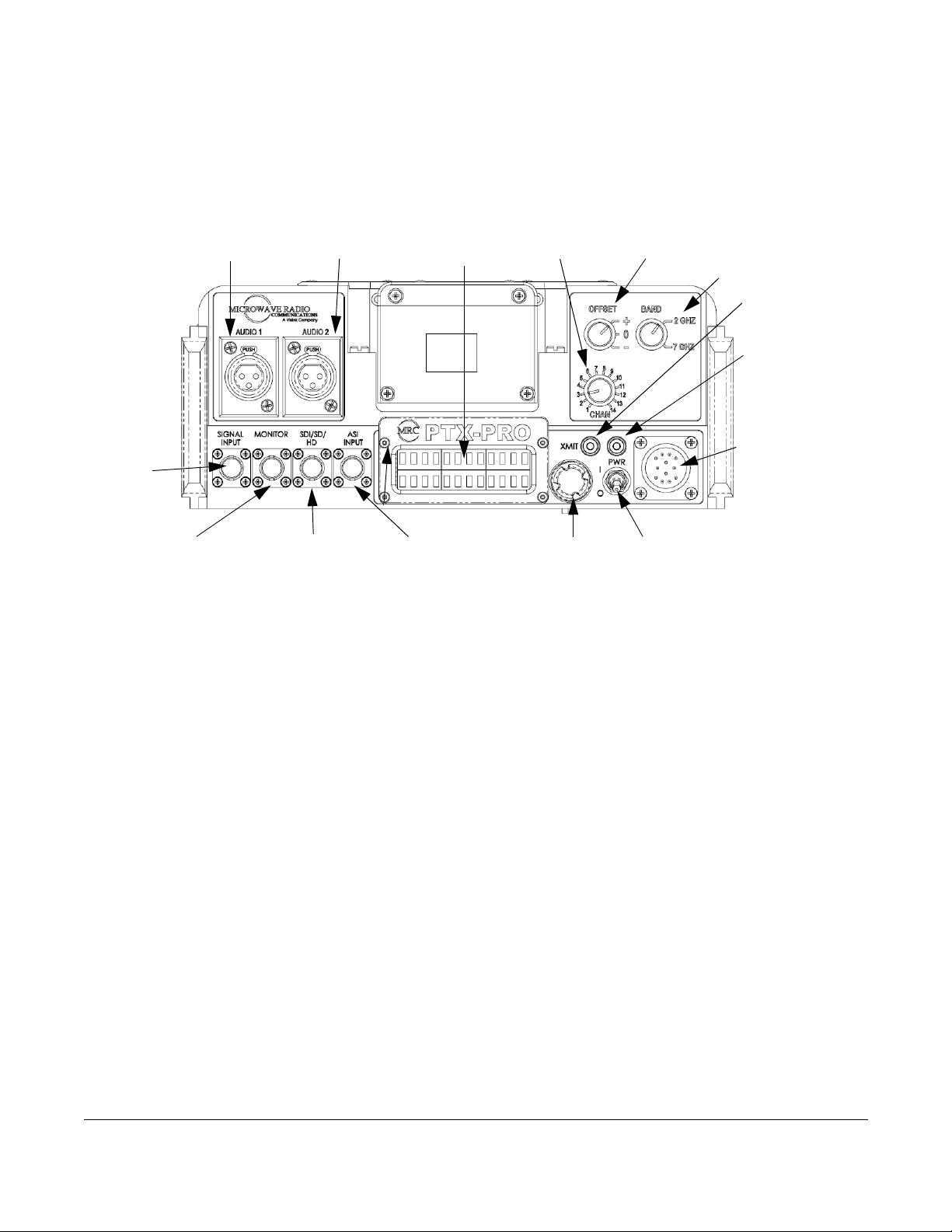
1.2 Rear Panel Connectors and Fuses
Controls, fuses, and connectors contained on the PTX-PRO rear panel are shown in the
following figure.
AUDIO 3 & 4,
L2/R2, or
AES-EBU
Connector
AC Fuse DC Fuse RF Output
Connector
RS 232
Connector
About the PTX-PRO 1-3PTX-PRO User and Technical Manual
AUDIO 3 & 4, L2/R2, or AES-EBU 10-Pin Female Connector Receives balanced audio inputs
for audio subcarriers 3 and 4 or MPEG L2/R2.
RF Output Type “N” 50 Ohm Female Connector Provides the RF output to the transmitting
antenna. The universal type “N” connector lets you use PTX-PRO for emergency restoration of
a Studio-Transmitter Link (STL) or Inter-City Relay (ICR) link.
AC Fuse Provides AC input power protection for units used with AC power sources.
DC Fuse Provides DC input power protection for units used with DC power sources.
Operating Voltage Fuse Rating
90 to 264 VAC, 50/60 Hz 2.0A, 250V AGC, Slow Blow
+11.0 to +36.0 VDC 15.0A, 250V, Slow Blow
CAUTION
RS-232 DB-9 Connector Provides a connection to a Windows-based PC when using the
Configurator software or connection for Wayside data.
Avoid possible equipment damage. If you are using a DC power source
for your PTX-PRO, do not exceed 36 volts DC input power.
1.3 Related Documents
• Glossary of Terms and Abbreviations (Part No. 400576-1)
• Channels and Frequencies Technical Information (Part No. 400580-1)
• Link Quality Technical Information (Part No. 400585-1)
1-4 About the PTX-PRO PTX-PRO User and Technical Manual

1.4 Channel Plans (2, 7, and 13)
1.4.1 The 2 GHz Channel Plan
The following table shows the 2 GHz BAS channel plan.
BAS
Channel
1 2028.500 2031.500 2034.500
2 2040.500 2043.500 2046.500
3 2052.500 2055.500 2058.500
4 2064.500 2067.500 2070.500
5 2076.500 2079.500 2082.500
6 2088.500 2091.500 2094.500
7 2100.500 2103.500 2106.500
8 2454.250 2458.500 2462.750
9 2471.000 2475.250 2479.500
10 2487.500 2491.750 2496.000
(-) Offset
(MHz)
(0) Offset
(MHz)
(+) Offset
(MHz)
1.4.2 The 7 GHz Channel Plan
The following table shows the channel plan for 6.4 to 7.2 GHz.
Channel
(-) Offset
(MHz)
(0) Center
(MHz)
(+) Offset
(MHz)
1 6881.250 6887.500 6893.750
2 6906.250 6912.500 6918.750
3 6931.250 6937.500 6943.750
4 6956.250 6962.500 6968.750
5 6981.250 6987.500 6993.750
6 7006.250 7012.500 7018.750
7 7031.250 7037.500 7043.750
8 7056.250 7062.500 7068.750
9 7081.250 7087.500 7093.750
10 7106.750 7112.500 7118.750
11 6431.250 6437.500 6443.750
12 6456.250 6462.500 6468.750
13 6481.250 6487.500 6493.750
14 6506.250 6512.500 6518.750
About the PTX-PRO 1-5PTX-PRO User and Technical Manual

1.4.3 The 13 GHz Channel Plan
The following table shows the channel plan for 12.7 to 13.25 GHz.
Channel
1
2
3
4
5
6
7
8
9
10
11
12
13
14
15
16
17
18
19
20
21
22
(-) Offset
(MHz)
N/A 12712.500 12718.750
12731.250 12737.500 12743.750
12756.250 12762.500 12768.750
12781.250 12787.500 12793.750
12806.250 12812.500 12818.750
12831.250 12837.500 12843.750
12856.250 12862.500 12868.750
12881.250 12887.500 12893.750
12906.250 12912.500 12918.750
12931.250 12937.500 12943.750
12956.250 12962.500 12968.750
12981.250 12987.500 12993.750
13006.250 13012.500 13018.750
13031.250 13037.500 13043.750
13056.250 13062.500 13068.750
13081.250 13087.500 13093.750
13106.250 13112.500 13118.750
13131.250 13137.500 13143.750
13156.250 13162.500 13168.750
13181.250 13187.500 13193.750
13206.250 13212.500 13218.750
13231.250 13237.500 N/A
(0) Center
(MHz)
(+) Offset
(MHz)
1-6 About the PTX-PRO PTX-PRO User and Technical Manual

2
Installing the PTX-PRO
This chapter describes how to install Transmitter (PTX-PRO).
CAUTION
If you modify the product without authorization from Vislink, you will void
the warranty.
2.1 Unpacking the PTX-PRO
Carefully unpack your new equipment to avoid damage.
• Locate all parts and accessories and verify that they are listed on the packing list.
Note
• Inspect the equipment for damage and that it is clean and dry.
• Inspect the cables, connectors, switches, and displays to ensure that they are not
broken, damaged, or loose.
If you discover damage after unpacking the system, report the damage as follows:
• Immediately file a claim with the shipping carrier.
DO NOT discard the container or packing material until you have inspected the
equipment and are sure there is no shipping damage. The container and
packing must be available in case you need to file a damage claim with the
shipping carrier.
• Forward a copy of the damage report to Vislink Customer Service.
• Contact Vislink Customer Service to determine the disposition of the equipment. See
Section 4.1, Getting Support for Your PTX-PRO on page 4-1.
2.2 Preparing to Install the PTX-PRO
The following sections describe the things you should consider before installing the DXL8000.
2.2.1 Operating in Safety
CAUTION
Ensure that the power being supplied matches the power required by
the equipment. You can find power ratings for equipment on a rating
plate, usually on the rear panel. Ensure that the electrical supply is
protected by over-current protection devices as required by the
applicable electrical codes. If necessary, consult a licensed electrician.
Installing the PTX-PRO 2-1PTX-PRO User and Technical Manual

WARNING - RF Power Hazard
WARNING
• Remove power from the unit before disconnecting any RF cables and before inspecting
damaged cables and/or antennas.
• Avoid standing in front of high gain antennas (such as a dish antenna) and never look
into the open end of a waveguide or cable where RF power may be present.
The following guidelines for safe operation were derived from OET bulletin 65, August 1997, as
recommended by the Federal Communications Commission (FCC).
The PTX-PRO was designed to provide services to broadcast ENG users under CFR 74
subpart F and 74.601 TV pickup stations. This unit, operated without an antenna, will not create
RF energy exceeding 1.0 mW/cm2, the FCC limit for exposure. Once connected to an antenna,
the potential for harmful exposure will be greatly enhanced.
In this situation, a certain distance from the radiator is to be maintained. Calculations need to be
performed to understand what that safe margin for exposure is. This is known as the Maximum
Permissible Exposure (MPE) limit.
Calculations provided are for common antennas often utilized in the ENG environment. The
following formula used is that suggested by OET 65.
The unit has high levels of RF power. Exposure to RF or microwave
power can cause burns and may be harmful to health.
Calculating MPE
EIRP = P * (10 ^ (G / 10)) = (antilog of G/10) * P
P = RF power delivered to the antenna in mW
G = Power gain of the antenna in the direction of interest relative to an isotropic radiator
R = distance to the center of radiation of the antenna in centimeters
S = MPE in mW/cm² (milliwatts per square centimeters)
Conversions
dBi to numeric gain = Antilog (dBi/10)
Feet to centimeters = Feet * 30.48
Centimeters to Feet = cm * .0328
4 π = 12.57
User Input
RF power delivered to the antenna = Watts
Antenna gain (referenced to isotropic antenna) = dBi
Distance from the center of radiation = Feet
2-2 Installing the PTX-PRO PTX-PRO User and Technical Manual

Calculation steps:
1. [P] RF power input. Watts to milliwatts = Watts * 1000
2. [G] Antenna gain dBi. Numeric gain = Antilog (dBi/10)
3. [EIRP] Multiply P * G
4. [R] Centimeters to feet = Centimeters * .0328
5. Square R
6. Multiply R² * 4π
7. [S] Divide (R² * 4π) into EIRP
S = Power Density in milliwatts per square centimeters.
Note
Reference
FCC OET Bulletin 65, August 1997 - Evaluating Compliance with FCC Guidelines for
Human Exposure to Radio Frequency Electromagnetic Fields
The following graph and associated table show the permissible exposure distance for various
antennas. Graphs and data will vary, based on the actual transmitter, output power, frequency,
and antenna utilized. One plot provides the permissible output of the transmitter for digital
modulation, and the other plot for analog modulation.
This information is provided, in accordance with the requirements set forth by the FCC, as a
guide for you assuming that users of this equipment are licensed and qualified to operate the
equipment per the guidelines and recommendations contained within the product user guides
and in accordance with any FCC rules that may apply.
At frequencies above 1500 MHz, S must not be greater than 1.
Installing the PTX-PRO 2-3PTX-PRO User and Technical Manual
Antenna
Gain (dBi)
020 7.9
532 12.6
16 113 44.5
20 178 70.1
35 1001 394.1
Distance from
Antenna (cm)
Minimum Safe
Minimum Safe
Distance from
Antenna (inch)
2.2.2 Powering and Grounding the PTX-PRO
For safe operation, all equipment must be properly grounded.
• Connect the unit to a common (vehicle or aircraft) ground.
• Make the ground wire as short and straight as possible.
CAUTION
Be sure the equipment grounding follows applicable electrical codes.
Never modify a grounded power plug to connect to an ungrounded
receptacle.
Ensure that the power being supplied matches the power required by
the equipment. You can find power ratings for equipment on a rating
plate, usually on the rear panel. Ensure that the electrical supply is
protected by over-current protection devices as required by the
applicable electrical codes. If necessary, consult a licensed electrician.
2-4 Installing the PTX-PRO PTX-PRO User and Technical Manual
2.3 Mounting on an MRC Tripod
For portable applications, the PTX-PRO is moved
from place to place. The power, antenna, and audio/
video connections are set up and removed each
time.
You can attach the PTX-PRO to a Quick Release
Mount for easy mounting on an MRC tripod (see
figure). The Quick Release Mount is attached to the
bottom of the PTX-PRO using four 1/2-inch long, #632, flat head screws.
You can keep the Quick Release Mount attached to
the PTX-PRO. The Quick Release Mount and PTXPRO are then attached to the Dovetail Adapter Plate
machined into the MRC tripod mount.
The versatility of the Quick Release Mount and a
mating Dovetail Adapter Plate let you attach the Dovetail Adapter Plate to the bottom of the
PTX-PRO and the Quick Release Mount to a non-MRC tripod, or vice versa.
Dovetail Adapter
Plate (Machined)
Quick
Release
Mount
MRC Tripod
Mount
2.4 Mounting on a Non-MRC Tripod
Option 1
To mount a PTX-PRO on a non-MRC tripod, attach
the Quick Release Mount to the bottom of the
PTX-PRO using four 1/2-inch long, #6-32, flat
head screws.
The Dovetail Adapter Plate is then attached to the
non-MRC tripod and the Quick Release Mount and
PTX-PRO assembly is attached to the Dovetail
Adapter Plate on the tripod mount.
Flat Head Screws
(4 Each)
Quick Release
Mount (Attached to
PTX-PRO)
Dovetail
Adapter
Plate
Tripod
Mount
Installing the PTX-PRO 2-5PTX-PRO User and Technical Manual
 Loading...