

Microwave Radio Communications PTX127T1CG User Manual
PTX-PRO
13 GHz Transmitter
User and Technical Manual
Manual Part No. 400590-1 Rev. B June 2009


Notices
About This Manual
Microsoft®, Windows®, and Internet Explorer® are registered
trademarks of Microsoft Corporation in the United States and/or
other countries.
Part number 400590-1
Revision B June 2009
PTX-PRO 13 GHz Transmitter (PTX-PRO)
Copyright
The information contained in this manual remains the property of
Microwave Radio Communications (MRC) and may not be used,
disclosed, or reproduced in any form whatsoever, without the
prior written consent of MRC.
MRC reserves the right to make changes to equipment and
specifications of the product described in this manual at any time
without notice and without obligation to notify any person of such
changes.
© 2009 Microwave Radio Communications
Microwave Radio Communications
101 Billerica Avenue - Bldg. 6
North Billerica, MA 01862-1256 USA
TEL: 800.490.5700
Proprietary Material
The information and design contained within this manual was
originated by and is the property of MRC. MRC reserves all
patent proprietary design, manufacturing, reproduction use, and
sales rights thereto, and to any articles disclosed therein, except
to the extent rights are expressly granted to others. The
foregoing does not apply to vendor proprietary parts.
MRC has made every effort to ensure the accuracy of the
material contained in this manual at the time of printing. As
specifications, equipment, and this manual are subject to change
without notice, MRC assumes no responsibility or liability
whatsoever for any errors or inaccuracies that may appear in this
manual or for any decisions based on its use. This manual is
supplied for information purposes only and should not be
construed as a commitment by MRC.
Quality Certification
Microwave Radio Communications is certified to ISO 9001:2000.
Changes or modifications not expressly approved by MRC could
void the user’s authority to operate the equipment.
+1.978.671.5700
Printed in U.S.A.
The Microwave Radio Communications and Vislink trademarks
and other trademarks are registered trademarks in the United
States and/or other countries.
General Safety Information
The following safety requirements, as well as local site
requirements and regulations, must be observed by personnel
operating and maintaining the equipment covered by this manual
to ensure awareness of potential hazards.
Notices Notices-iPTX-PRO User and Technical Manual

WARNING - RF Power Hazard
High levels of RF power are present in the unit. Exposure to RF
or microwave power can cause burns and may be harmful to
health.
Remove power from the unit before disconnecting any RF cables
and before inspecting damaged cables and/or antennas.
Avoid standing in front of high gain antennas (such as a dish
antenna) and never look into the open end of a waveguide or
cable where RF power may be present.
Note
Calculations provided are for common antennas often utilized in
the ENG environment. The following formula used is that
suggested by OET 65.
Hazardous RF radiation limits and recommended
distances may vary by country. Ensure that all
applicable state and federal regulations are
observed when using this transmitter.
Calculating MPE
RF Exposure - Safe Working Distances
MRC provides this warning for safety purposes with the intent to
inform the user of the potential hazard of RF exposure. The
following guidelines for safe operation were derived from OET
bulletin 65, August 1997, as recommended by the Federal
Communications Commission (FCC).
The PTX-PRO 13 GHz Transmitter is a mobile transmitter
system designed to provide services to broadcast ENG users
under CFR 74 subpart F and 74.601 TV pickup stations. This
unit, operated without an antenna, will not create RF energy
exceeding 1.0 mW/cm2, the FCC limit for exposure. Once
connected to an antenna, the potential for harmful exposure will
be greatly enhanced.
In this situation, a certain distance from the radiator is to be
maintained. Calculations need to be performed to understand
what that safe margin for exposure is. This is known as the
Maximum Permissible Exposure (MPE) limit.
EIRP = P * (10 ^ (G / 10)) = (antilog of G/10) * P
P = RF power delivered to the antenna in mW
G = Power gain of the antenna in the direction of interest relative
to an isotropic radiator
R = distance to the center of radiation of the antenna in
centimeters
S = MPE in mW/cm² (milliwatts per square centimeters)
Conversions
dBi to numeric gain = Antilog (dBi/10)
Feet to centimeters = Feet * 30.48
Centimeters to Feet = cm * .0328
4 π = 12.57
User Input
RF power delivered to the antenna = Watts
Antenna gain (referenced to isotropic antenna) = dBi
Distance from the center of radiation = Feet
Calculation steps:
Notices Notices-iiPTX-PRO User and Technical Manual
1. [P] RF power input. Convert watts to milliwatts =
Watts * 1000
2. [G] Antenna gain dBi. Convert to numeric gain =
Antilog (dBi/10)
3. [EIRP] Multiply P * G
4. [R] Convert centimeters to feet = Centimeters * .0328
5. Square R
6. Multiply R² * 4π
7. [S] Divide (R² * 4π) into EIRP
S = Power Density in milliwatts per square centimeters.
Note: At frequencies above 1500 MHz, S must not be
greater than 1
Reference
FCC OET Bulletin 65, August 1997 - Evaluating
Compliance with FCC Guidelines for Human Exposure to
Radio Frequency Electromagnetic Fields
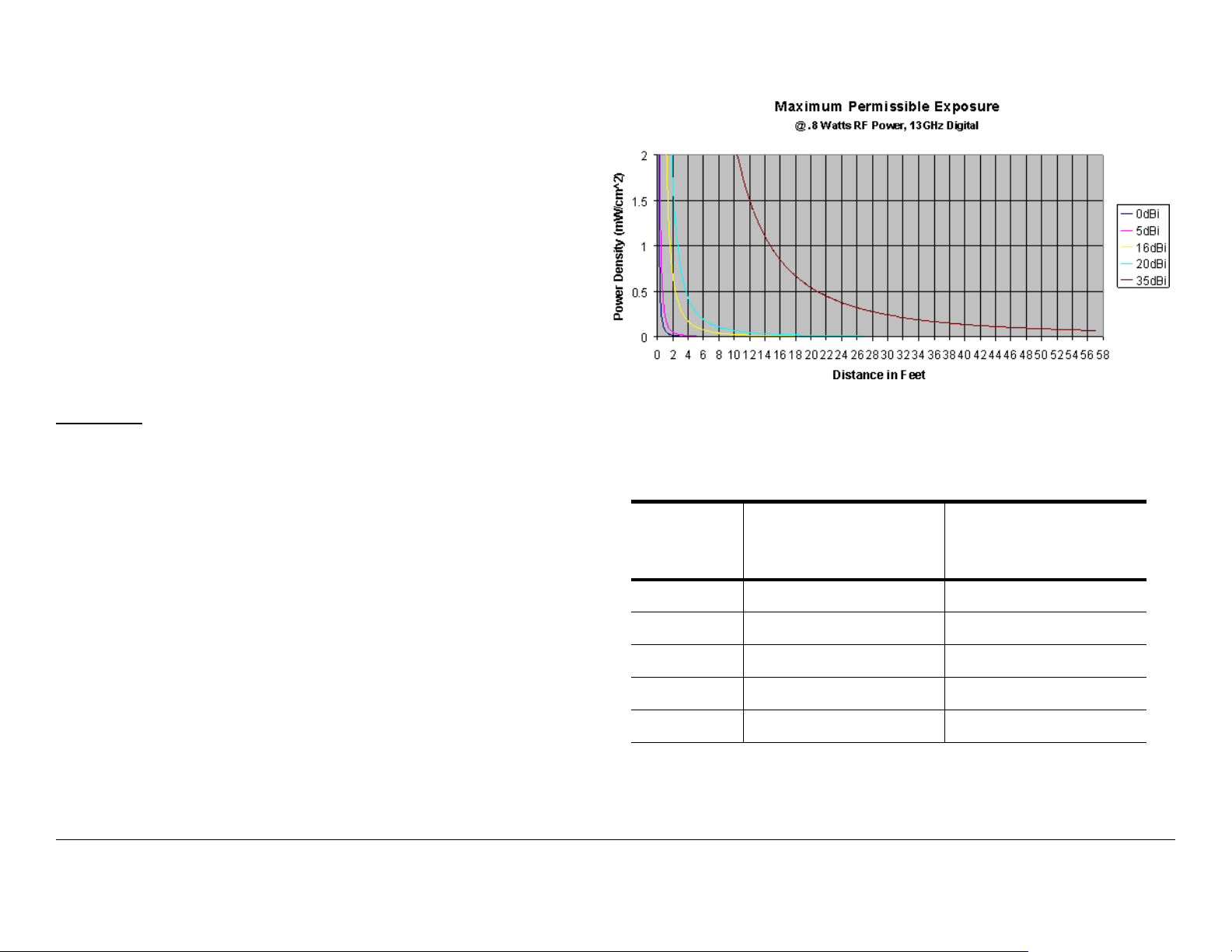
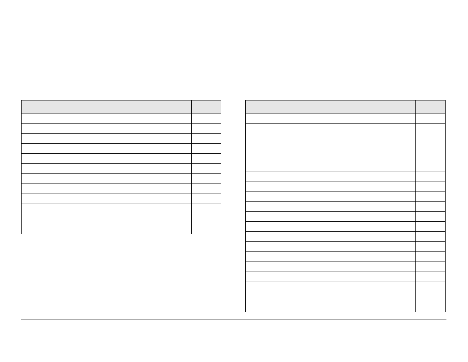
Figure 1: Digital Modulation
The following table reflects the graphic representations above.
Tabl e 1:
The example shown in Figure 1 is a typical graph for an
MRC PTX-PRO 13 GHz Transmitter and shows the
permissible exposure distance for various antennas.
Graphs and data will vary, based on the actual transmitter,
output power, frequency, and antenna utilized. The plot
provides the permissible output of the transmitter for digital
modulation
MRC, in accordance with the requirements set forth by the
FCC, provides this information as a guide to the user. It is
assumed that the users of this equipment are licensed and
qualified to operate the equipment per the guidelines and
recommendations contained within the product user guides
and in accordance with any FCC rules that may apply.
Antenna
Gain (dBi)
08 3.15
5 45 17.71
16 51 20.07
20 80 31.49
35 449 176.73
Minimum
Distance from
Antenna (cm)
Minimum Distance
from Antenna (inch)
Notices Notices-iiiPTX-PRO User and Technical Manual

Conventions
Pay special attention to information marked in one of the
following ways:
WARNING
CAUTION
Note
Notes provide additional information to assist you
in using and maintaining the equipment.
Follow WARNINGS closely to prevent
personal injury or death.
Follow CAUTIONS to prevent damage to
the equipment.
Symbols Used
The following symbols may be used on the equipment or may be
contained in this manual:
Symbol Meaning
WARNING: General Warning. Risk of Danger
WARNING: Risk of Electric Shock
CAUTION: Electrostatic Discharge. Possible
Damage to Equipment
Fuse - Identifies fuses or their location.
-OR-
Frame or Chassis Ground - Identifies the frame or
chassis terminal.
Earth Ground - Identifies the earth ground terminal
Protective Earth Ground - Identifies any terminal
which is intended for connection to an external
conductor for protection against electric shock in
case of a fault, or the terminal on a protective earth
electrode.
Waste Electrical and Electronic Equipment
(WEEE) - The product must not be disposed of
with other waste at the end of its life cycle. It is
the user’s responsibility to dispose of the waste
equipment by handing it over to a designated
collection point for recycling.
Notices Notices-ivPTX-PRO User and Technical Manual

Contents
Introduction - - - - - - - - - - - - - - - - - - - - - - - - - - - 1-1
For Whom It’s Written - - - - - - - - - - - - - - - - - - - - - - - - 1-1
Related Documents - - - - - - - - - - - - - - - - - - - - - - - - - - 1-1
Ordering Documentation - - - - - - - - - - - - - - - - - - - - - - 1-1
Calling for Service - - - - - - - - - - - - - - - - - - - - - - - - - - - 1-1
Tell Us What You Think! - - - - - - - - - - - - - - - - - - - - - - 1-2
Product Description- - - - - - - - - - - - - - - - - - - - - 2-1
Description - - - - - - - - - - - - - - - - - - - - - - - - - - - - - - - - 2-1
Options - - - - - - - - - - - - - - - - - - - - - - - - - - - - - - - - 2-1
Power Options - - - - - - - - - - - - - - - - - - - - - - - - - - - 2-2
Mounting and Deployment Options - - - - - - - - - - - - 2-2
System Integration - - - - - - - - - - - - - - - - - - - - - - - - 2-3
Routine Operation - - - - - - - - - - - - - - - - - - - - - - 3-1
Overview of Controls, Indicators and Connectors - - - - - 3-1
Front Panel Controls, Indicators, and Connectors - - 3-2
Rear Panel Connectors and Fuses- - - - - - - - - - - - - 3-4
Preparing for Operation - - - - - - - - - - - - - - - - - - - - - - - 3-5
Portable Deployment - Typical - - - - - - - - - - - - - - - - 3-5
Powering the PTX-PRO Transmitter- - - - - - - - - - - - 3-5
Using the Display Screens - - - - - - - - - - - - - - - - - - - - - 3-6
PTX-PRO Monitoring Operations - - - - - - - - - - - - - - - - 3-6
Using the Monitor Screens in COFDM Mode - - - - - - 3-7
Using the Monitor Screens in ASI/SDI Input Mode - - 3-7
Using the Monitor Screens in Ext IF Input Mode - - - 3-7
Using the Monitor Screens in LMS-T Mode - - - - - - - 3-7
PTX-PRO Control Operations- - - - - - - - - - - - - - - - - - 3-12
Front Panel vs. Configurator Settings - - - - - - - - - - - - 3-14
Troubleshooting - - - - - - - - - - - - - - - - - - - - - - - 4-1
Power LED - - - - - - - - - - - - - - - - - - - - - - - - - - - - - - - - 4-1
Display Messages - - - - - - - - - - - - - - - - - - - - - - - - - - - 4-2
Error Codes - - - - - - - - - - - - - - - - - - - - - - - - - - - - - - - - 4-3
Error Status - - - - - - - - - - - - - - - - - - - - - - - - - - - - - 4-3
Primary Error Code - - - - - - - - - - - - - - - - - - - - - - - - 4-3
Operational Problems - - - - - - - - - - - - - - - - - - - - - - - - - 4-6
Configurator Troubleshooting - - - - - - - - - - - - - - - - - - - 4-7
Configurator Error Messages - - - - - - - - - - - - - - - - - 4-7
Configurator Operational Problems - - - - - - - - - - - - - 4-8
Advanced Operation - - - - - - - - - - - - - - - - - - - - 5-1
Before You Begin - - - - - - - - - - - - - - - - - - - - - - - - - - - - 5-1
PTX-PRO - - - - - - - - - - - - - - - - - - - - - - - - - - - - - - 5-1
Configurator Software - - - - - - - - - - - - - - - - - - - - - - 5-1
Settings - - - - - - - - - - - - - - - - - - - - - - - - - - - - - - - - 5-1
System Rules - - - - - - - - - - - - - - - - - - - - - - - - - - - - 5-2
Configurations- - - - - - - - - - - - - - - - - - - - - - - - - - - - 5-2
Channel Plans - - - - - - - - - - - - - - - - - - - - - - - - - - - 5-3
Create or Update a Configuration - - - - - - - - - - - - - - - - 5-3
Using the Configurator Software - - - - - - - - - - - - - - - 5-3
Determine Licensed Options - - - - - - - - - - - - - - - - - 5-3
Create New Configuration On-Line - - - - - - - - - - - - - 5-5
Load and Modify Configuration Settings On- Line- - 5-10
Load Configuration File into Radio On-Line - - - - - - 5-15
Change Preset Names in On-Line Mode - - - - - - - - 5-16
Create Channel Plan Offline - - - - - - - - - - - - - - - - - 5-17
Modify Channel Plan in Offline Mode- - - - - - - - - - - 5-18
Load and Modify a Channel Plan On-Line - - - - - - - 5-19
Load Channel Plan File into Radio On-Line - - - - - - 5-20
Add Licensed Option - - - - - - - - - - - - - - - - - - - - - - 5-21
Installation - - - - - - - - - - - - - - - - - - - - - - - - - - - 6-1
Unpacking - - - - - - - - - - - - - - - - - - - - - - - - - - - - - - - - 6-1
Initial Inspection - - - - - - - - - - - - - - - - - - - - - - - - - - - - - 6-1
Damage in Shipment - - - - - - - - - - - - - - - - - - - - - - - - - 6-1
Mounting and Cabling - - - - - - - - - - - - - - - - - - - - - - - - - 6-2
Portable Deployment - - - - - - - - - - - - - - - - - - - - - - - 6-2
Power Connections - - - - - - - - - - - - - - - - - - - - - - - - - - 6-5
Contents Contents-1PTX-PRO User and Technical Manual

Power Requirements - - - - - - - - - - - - - - - - - - - - - - 6-5
Power Supply and Distribution - - - - - - - - - - - - - - - - 6-5
Power Cable Assemblies - - - - - - - - - - - - - - - - - - - 6-6
Additional Powering Notes - - - - - - - - - - - - - - - - - - 6-7
Grounding - - - - - - - - - - - - - - - - - - - - - - - - - - - - - - - - 6-8
Audio Connections - - - - - - - - - - - - - - - - - - - - - - - - - - 6-8
Front Panel Audio Connections - - - - - - - - - - - - - - - 6-8
Rear Panel Audio Connections - - - - - - - - - - - - - - - 6-9
MPEG Audio Input - - - - - - - - - - - - - - - - - - - - - - - - 6-9
AES/EBU Audio Input - - - - - - - - - - - - - - - - - - - - - 6-10
Video Connections - - - - - - - - - - - - - - - - - - - - - - - 6-10
Signal Connections - - - - - - - - - - - - - - - - - - - - - - - - - 6-11
Data Connections - - - - - - - - - - - - - - - - - - - - - - - - - - 6-11
PTX-PRO Programming - - - - - - - - - - - - - - - - - - - 6-12
Wayside Data - - - - - - - - - - - - - - - - - - - - - - - - - - 6-12
Panel Data Connectors - - - - - - - - - - - - - - - - - - - - 6-13
Multipurpose Data Cable - - - - - - - - - - - - - - - - - - - 6-13
Networking - - - - - - - - - - - - - - - - - - - - - - - - - - - - 6-14
Powering Up - - - - - - - - - - - - - - - - - - - - - - - - - - - - - - 6-16
Checks before power-up - - - - - - - - - - - - - - - - - - - 6-16
Initial power-up - - - - - - - - - - - - - - - - - - - - - - - - - - 6-16
Configurator Software Installation - - - - - - - - - - - - - - - 6-17
PC Requirements - - - - - - - - - - - - - - - - - - - - - - - - 6-17
Installing Configurator Software - - - - - - - - - - - - - - 6-17
Product Modifications - - - - - - - - - - - - - - - - - - - - - - - - 6-20
Replacement Parts - - - - - - - - - - - - - - - - - - - - - 7-1
External Cables - - - - - - - - - - - - - - - - - - - - - - - - - - - - - 7-1
Mounting Hardware - - - - - - - - - - - - - - - - - - - - - - - - - - 7-1
Power Fuses - - - - - - - - - - - - - - - - - - - - - - - - - - - - - - - 7-2
Supported Repairs - - - - - - - - - - - - - - - - - - - - - - - - - - - 7-2
Theory of Operation - - - - - - - - - - - - - - - - - - - - 8-1
System Architecture - - - - - - - - - - - - - - - - - - - - - - - - - - 8-1
System Theory of Operation - - - - - - - - - - - - - - - - - - - - 8-2
MPEG/COFDM Encoder/Modulator Module- - - - - - - 8-2
Contents Contents-2PTX-PRO User and Technical Manual

1
Introduction
1.1 For Whom It’s Written
• Approximate purchase date.
• Firmware version, which appears on the PTX-PRO
alphanumeric display at startup.
- OR -
This manual is intended for use by qualified operators, installers,
and service personnel. Users of this manual should already be
familiar with the basic concepts of radio, video, and audio.
1.2 Related Documents
• Van Portable Systems User and Technical Manual
(part no. 400522-1)
• Glossary of Terms and Abbreviations (Part No. 400576-1)
1.3 Ordering Documentation
Any of the above manuals may be ordered by contacting MRC
Customer Service:
Business Hours: Monday - Friday
8:00 AM - 7:00 PM Eastern Time (US)
(0800 - 1900 hrs US ET)
Telephone: 800.490.5700 (Press 3)
• Firmware version(s) displayed on the Main page of the
MRC Radio Configurator (Configurator), when the
Configurator software is connected to the PTX-PRO.
1.4 Calling for Service
MRC Technical Support is available 24 hours a day, 7 days a
week. During regular business hours you can reach our expert
staff directly.
Business Hours: Monday - Friday
8:00 AM - 5:00PM Eastern Time (US)
(0800 - 1700 hrs US ET)
Telephone: 888.777.9221 (US and Canada)
+1.978.671.5929
E-mail: technicalsupport@mrcbroadcast.com
After regular business hours and on weekends and holidays, you
can also reach our expert staff as follows:
+1.978.671.5700 (Press 3)
E-mail: customerservice@mrcbroadcast.com
When contacting Customer Service, please have the following
information available:
• Model number and serial number of the unit. This is
located on a label on the bottom of each unit.
Telephone: 888.777.9221 (US and Canada)
+1.978.671.5929
Your call will be automatically forwarded to the on-call Technical
Support specialist.
When contacting Technical Support, please have the following
information available:
Introduction 1-1PTX-PRO User and Technical Manual

• Model number and serial number of the unit. This is
located on a label on the bottom of each unit.
• Approximate purchase date.
• Firmware version, which appears on the PTX-PRO
alphanumeric display at startup.
- OR -
• Firmware version(s) displayed on the Main page of the
MRC Radio Configurator (Configurator), when the
Configurator software is connected to the PTX-PRO.
1.5 Tell Us What You Think!
We’d appreciate any comments or suggestions you have about
this manual. The more feedback we get, the better the manuals
get!
If you’re viewing this manual electronically, it’s easy - just click on
the link below to send us an E-mail.
Feedback
Or, you can E-mail our Technical Support team at:
technicalsupport@mrcbroadcast.com
Be sure to tell us what product you’re writing about, and which
document.
Introduction 1-2PTX-PRO User and Technical Manual
2
Product Description
2.1 Chapter Overview
This chapter provides an overall description of the PTX-PRO
13 GHz Transmitter (PTX-PRO) components, options, and
capabilities.
Here are the topics covered:
Topic Page
microwave signal outputs for communications purposes.
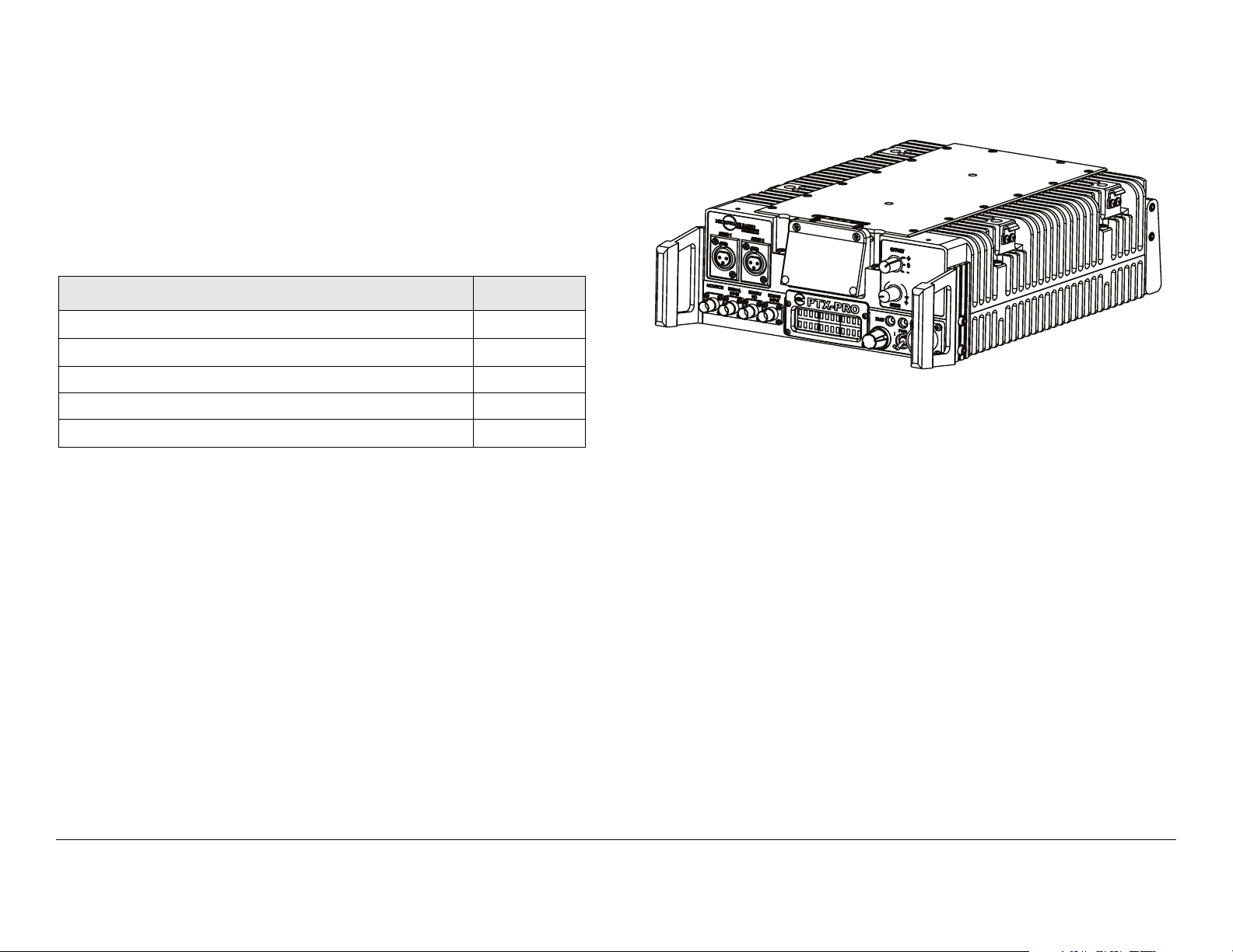
Figure 2-1: PTX-PRO Transmitter - Typical
Description
Options
Power Options 2-2
Mounting and Deployment Options 2-2
System Integration
2-1
2-1
2-3
2.2 Description
The PTX-PRO, as shown in Figure 2-1, is used for digital video
microwave communications and is designed to be a highly
reliable, flexible, and compact portable microwave transmitter for
either tripod or mobile applications.
The PTX-PRO is ideal for portable Electronic News Gathering
(ENG), Digital Video Broadcasting (DVB), mobile
communication, wireless airborne networks, and Outside
Broadcast (OB) systems.
The PTX-PRO architecture allows you the maximum flexibility in
configuration, siting, and operation. The PTX-PRO is a versatile
portable transmitter designed to accept a 70 MHz IF input signal
or composite video signal, audio signals, SD/HD SDI signals, or
ASI/SDI signals from external sources and to provide 13 GHz
The PTX-PRO accepts either external 70 MHz, external IF,
composite video (CV), HD or SD SDI, or SDI/ASI input signals
and up-converts these signals to the 13 GHz RF band.
The RF frequency synthesizer circuit included in the IF/RF
module, in conjunction with the command and control power
supply module, provides the means to channelize RF video and
audio signals in the 13 GHz RF band, as applicable to the
configuration of the PTX-PRO.
Standard U.S. FCC band plans, as well as customer-created
channel plans, may be customized using the Configurator
software.
The PTX-PRO includes MPEG/CODFM modules and serves as
a stand-alone digital video microwave transmission system.
2.2.1 Options
All configurations are available with either NTSC or PAL system
modulation.
Product Description 2-1PTX-PRO User and Technical Manual
PTX-PRO options consist of the following:
Standard and High Definition Video All PTX-PRO
configurations are available with Standard Definition (SD) or SD
and optional High Definition (HD) video technologies.
Antenna Options The PTX-PRO is fully compatible with the
MRC family of transmit antennas, including the following:
• MRC MegaHorn Compact Horn
• MRC 2, 3, and 4 ft. Parabolic Antennas.
Contact your Sales Representative to explore the antenna
choices available.
2.2.2 Power Options
The architecture of the PTX-PRO allows a number of options for
the external power source. The PTX-PRO configurations
operate on the following external AC or DC power sources:
• 90 to 264 VAC, 50/60 Hz
• +11.0 to +36.0 VDC
A built-in universal AC and DC power supply provides full
flexibility in choosing power sources. For additional information,
refer to the “Installation” Chapter on page 6-1 .
Fuse ratings for the AC and DC power sources are shown in
Table 2-1.
CAUTION
Refer to the “Installation” Chapter on page 6-1 for additional
information.
Avoid possible equipment damage. If you
are using a DC power source for your PTXPRO, do not exceed 36 volts DC input
power.
2.2.3 Mounting and Deployment Options
For more details on installation of the PTX-PRO in various
applications, see the “Installation” Chapter on page 6-1.
Portable Deployment In portable applications, the PTX-PRO is
typically mounted on an MRC Quick Release Mount for easy
attachment to an MRC tripod. The Quick Release Mount
connects to a Dovetail Adapter Plate machined into the MRC
tripod mount. Other mounting options are available.
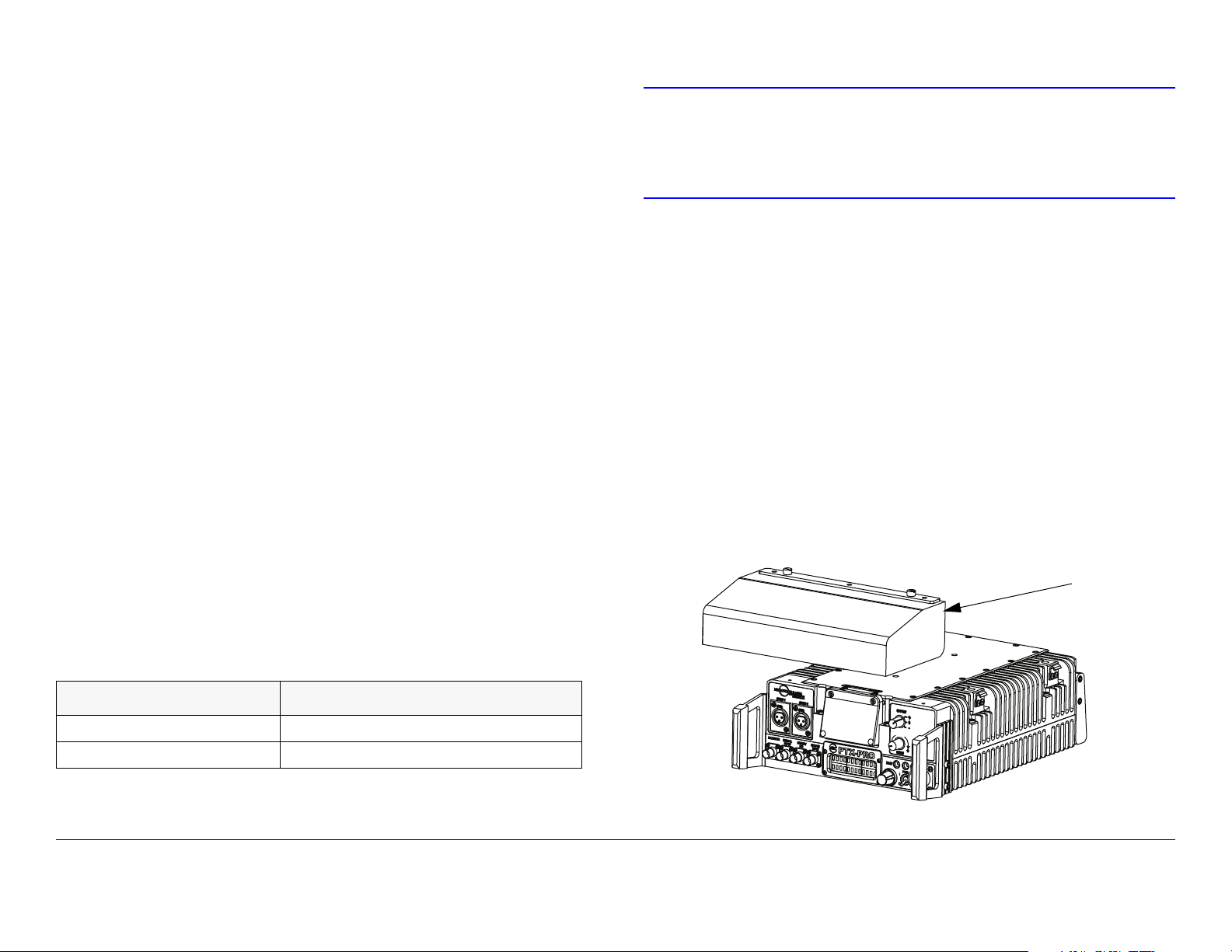
An optional Rain Shield, as shown in Figure 2-2, is available.
Figure 2-2: PTX-PRO with Optional Rain Shield
Optional
Rain
Shield
Table 2-1: Fuse Ratings
Operating Voltage Fuse Rating
90 to 264 VAC, 50/60 Hz 2.0A, 250V AGC, Slow Blow
+11.0 to +36.0 VDC 15.0A, 250V, Slow Blow
Product Description 2-2PTX-PRO User and Technical Manual

2.2.4 System Integration
System Operation Once the PTX-PRO is connected and
powered up, system settings can be selected or modified from
the front panel of the PTX-PRO.
System Configurations The PTX-PRO offers two levels of
system configurations designed to match the needs of different
personnel.
For the field operator, the PTX-PRO has up to nine Presets that
can be selected from the front panel. Each Preset controls key
parameters such as modulation, frequency, and audio and video
settings. Additional settings that may be controlled from the front
panel include channel and offset.
For the advanced operator and technical staff, the Configurator
software allows complete control of parameters in the PTX-PRO.
The Configurator software runs on a Microsoft Windows-based
PC and connects to the PTX-PRO via an RS-232 serial interface
cable.
Interfacing a PC to the PTX-PRO provides complete control of
PTX-PRO Presets. You can read the current settings, program
new settings, or return the units to their factory default settings.
The Configurator software automatically detects the hardware
and licensed options installed in PTX-PRO and assigns the
appropriate configurations to the correct hardware.
Product Description 2-3PTX-PRO User and Technical Manual

Product Description 2-4PTX-PRO User and Technical Manual
3
Routine Operation
3.2 Overview of Controls, Indicators and Connectors
3.1 Chapter Overview
This chapter provides basic information that will enable you to
operate your PTX-PRO 13 GHz Transmitter (PTX-PRO).
Here are the topics covered:
Topic Page
Overview of Controls, Indicators and Connectors 3-1
Preparing for Operation 3-5
Portable Deployment - Typical 3-5
Powering the PTX-PRO Transmitter 3-5
Using the Display Screens 3-6
PTX-PRO Monitoring Operations 3-6
Using the Monitor Screens in COFDM Mode 3-7
Using the Monitor Screens in ASI/SDI Input Mode 3-7
Using the Monitor Screens in Ext IF Input Mode 3-7
Using the Monitor Screens in LMS-T Mode 3-7
PTX-PRO Control Operations 3-12
Front Panel vs. Configurator Settings 3-14
For a summary of settings that can be made with the PTX-PRO
front panel control switches and which settings are made using
the Configurator software, see Section 3.7 on page 3-14.
Information on settings made with the MRC Radio Configurator
(Configurator) software can be found in the “Advanced
Operation” Chapter on page 5-1.
This section describes the controls, indicators, and connectors
used on the PTX-PRO.
Controls, indicators, and connectors contained on the various
configurations of the PTX-PRO are identified and described
below. Topics covered are as follows:
Topic Page
Front Panel Controls, Indicators, and Connectors 3-2
PTX-PRO Front Panel Controls, Indicators, and
Connectors
Alphanumeric Display 3-2
OFFSET Switch 3-2
CHAN Switch 3-2
SIGNAL INPUT BNC Connector 3-2
MONITOR BNC Connector 3-2
PWR LED 3-2
SDI/HD/SD BNC Connector 3-3
SDI/ASI INPUT BNC Connector 3-3
Control Switch 3-3
XMIT LED 3-4
PWR Switch 3-4
AC/DC Power Connector 3-4
Rear Panel Connectors and Fuses 3-4
AUDIO 3 & 4/AES-EBU Connector 3-4
RF Output Type “N” Connector 3-4
AC Fuse 3-4
DC Fuse 3-5
3-2
Routine Operation 3-1PTX-PRO User and Technical Manual
RS 232 DB-9 Connector 3-5
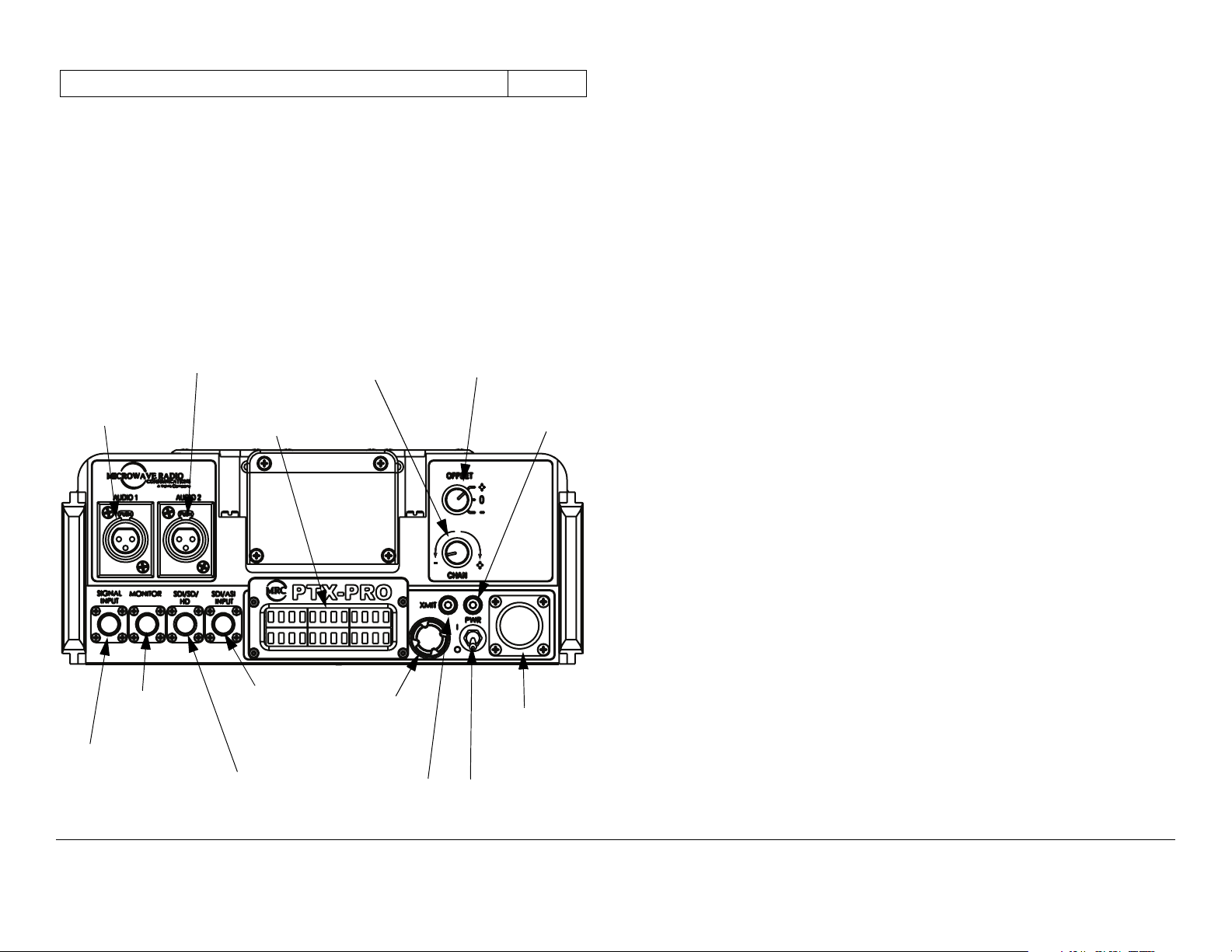
3.2.1 Front Panel Controls, Indicators, and Connectors
Each of these controls, indicators, and connectors are described
in more detail in the following paragraphs. Controls, indicators,
and connectors contained on the PTX-PRO front panel are
shown in Figure 3-1.
Figure 3-1: PTX-PRO Front Panel Controls, Indicators, and Connectors
AUDIO 1
Connector
AUDIO 2
Connector
Alphanumeric
Display
CHAN
Switch
OFFSET
Switch
PWR
LED
AUDIO 1 and AUDIO 2 XLR Connectors Each front panel
XLR AUDIO connector receives one channel of balanced audio
input.
Alphanumeric Display The PTX-PRO front panel contains a
two-line by 12-character alphanumeric display. The display
works in conjunction with the control switch to allow you to
monitor system status and to control system settings.
OFFSET Switch The front panel three-position OFFSET switch
provides selection of + (plus), 0 (center), or - (minus) channel
offset.
Note that OFFSET - (minus) cannot be selected for Channel 1
and OFFSET + (plus) cannot be selected for Channel 22.
CHAN Switch The front panel CHAN selector switch is used to
select the operating channel required. The CHAN selector
switch allows selection of 22 channels in the 13 GHz band.
Rotating the switch clockwise incrementally increases the
channel number and rotating the switch counterclockwise
decreases the channel number. The selected channel is
displayed on the Main screen of the alphanumeric display.
MONITOR
Connector
SIGNAL
INPUT
Connector
SDI/ASI
INPUT
Connector
SDI/SD/HD
Connector
Control
Switch
XMIT
LED
AC/DC
Power
Connector
PWR
Switch
SIGNAL INPUT BNC Connector The front panel SIGNAL
INPUT 75 ohm BNC female connector provides the input
connection for 70 MHz IF or composite video to the unit.
MONITOR BNC Connector The front panel MONITOR 75 ohm
BNC female connector provides a 70 MHz output for external
signal monitoring.
PWR LED The front panel PWR (power) LED is a multi-color
status LED. PWR LED indications are as follows:
Routine Operation 3-2PTX-PRO User and Technical Manual
WARNING
A Major Alarm may also indicate a potential
safety hazard.
Shut down the PTX-PRO and disconnect
power.
LED Color Meaning
----- Power is not on in the unit.
Green Power is on and no errors are detected.
Amber Minor Alarm - Power is on but some part of
the system reports an abnormal condition
that might impair performance.
Red Major Alarm - Power is on but there is a
failure or error that prevents normal
operation.
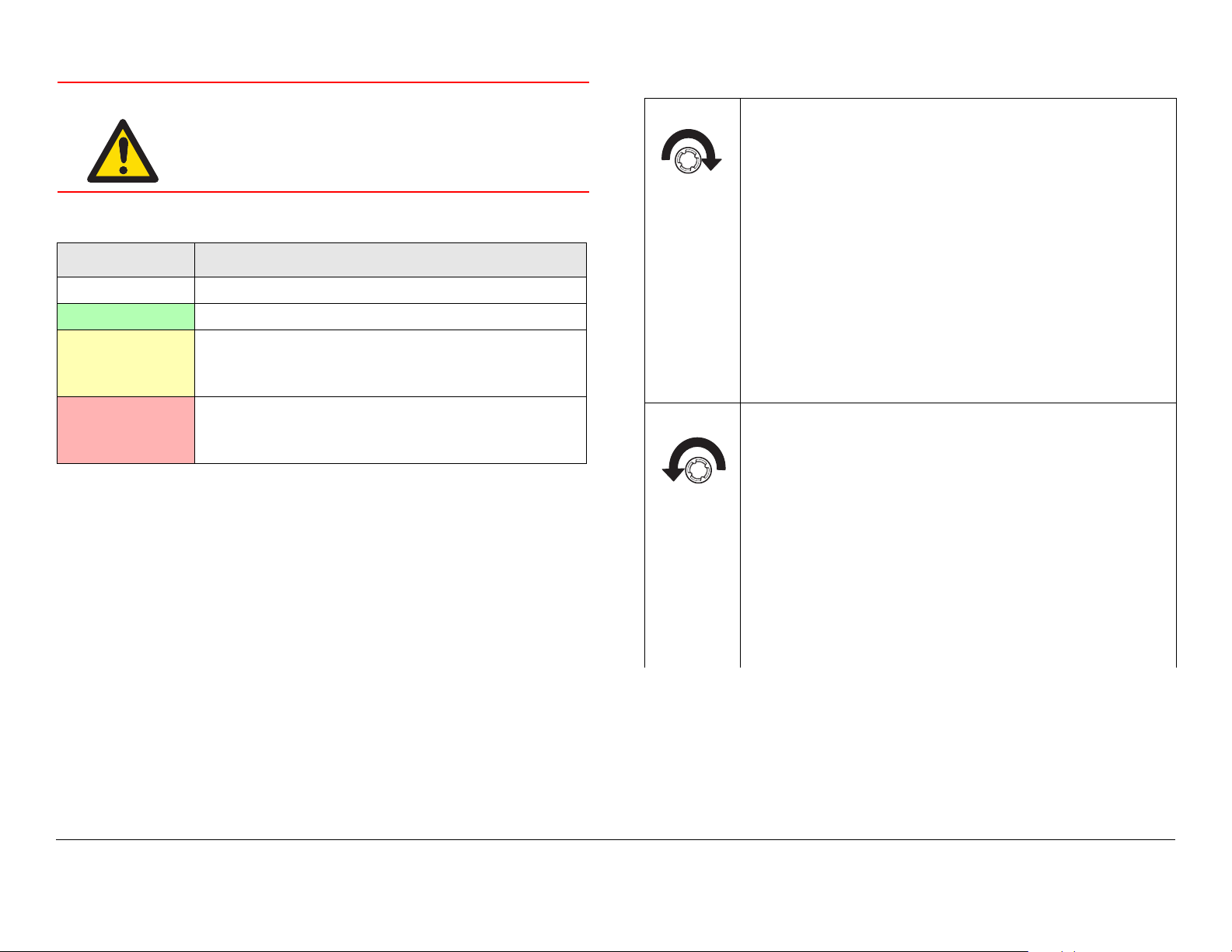
Turn the control switch to the right (cw) to view
Monitor options.
Monitor options are dependent upon the Preset
operating mode selected and provide current
status of the PTX-PRO. Status includes, but is
not limited to, the following:
• Frequency Setting
• Output Attenuation Level
• Frequency Band
• Operating Mode
• System Errors.
Turn the control switch to the left (ccw) to view
Command options.
SDI/HD/SD BNC Connector The front panel SDI/HD/SD 75
ohm BNC female connector provides the HD/SD/SDI data
stream input to the unit.
SDI/ASI INPUT BNC Connector The front panel SDI/ASI
INPUT 75 ohm BNC female connector provides SDI or ASI
inputs to the unit.
Control Switch Routine PTX-PRO operating settings are
controlled by the front panel control switch. Turning the control
switch right (cw) displays monitor options, turning the control
switch left (ccw) displays command setting options, and
pressing the control switch in makes selections as described
below:
Routine Operation 3-3PTX-PRO User and Technical Manual
The Command options allow control of the PTXPRO, including:
• Change Preset
• Change Video Mode to SD or HD
• Change SD or HD Video Mode Settings
• Change Color Bar Settings
• Setting Output Attenuation
Pressing the control switch causes an action to
occur.
Command Options
• If the displayed setting is Chng Preset, Chng VI
Mode, Chng SD/HD VI, Chng Clr Bar, or Set TX
VVA, pressing the control switch causes the
displayed setting to blink.
Turning the control switch cw or ccw then displays
the other options for that setting.
When the desired option is displayed, pressing the
control switch selects that option.
Transmit
• Pressing the control switch for one second changes
the transmitter to the transmit mode from the
standby mode.
• Pressing the control switch for one second changes
the transmitter from the transmit mode to the
standby mode.
XMIT LED When the PTX-PRO front panel control switch is
pressed for one second, the transmitter changes from the
standby mode to the transmit mode or from the transmit mode to
the standby mode. When the transmitter is in the transmit mode,
the front panel XMIT LED illuminates blue. When the transmitter
is in the standby mode, the XMIT LED is off.
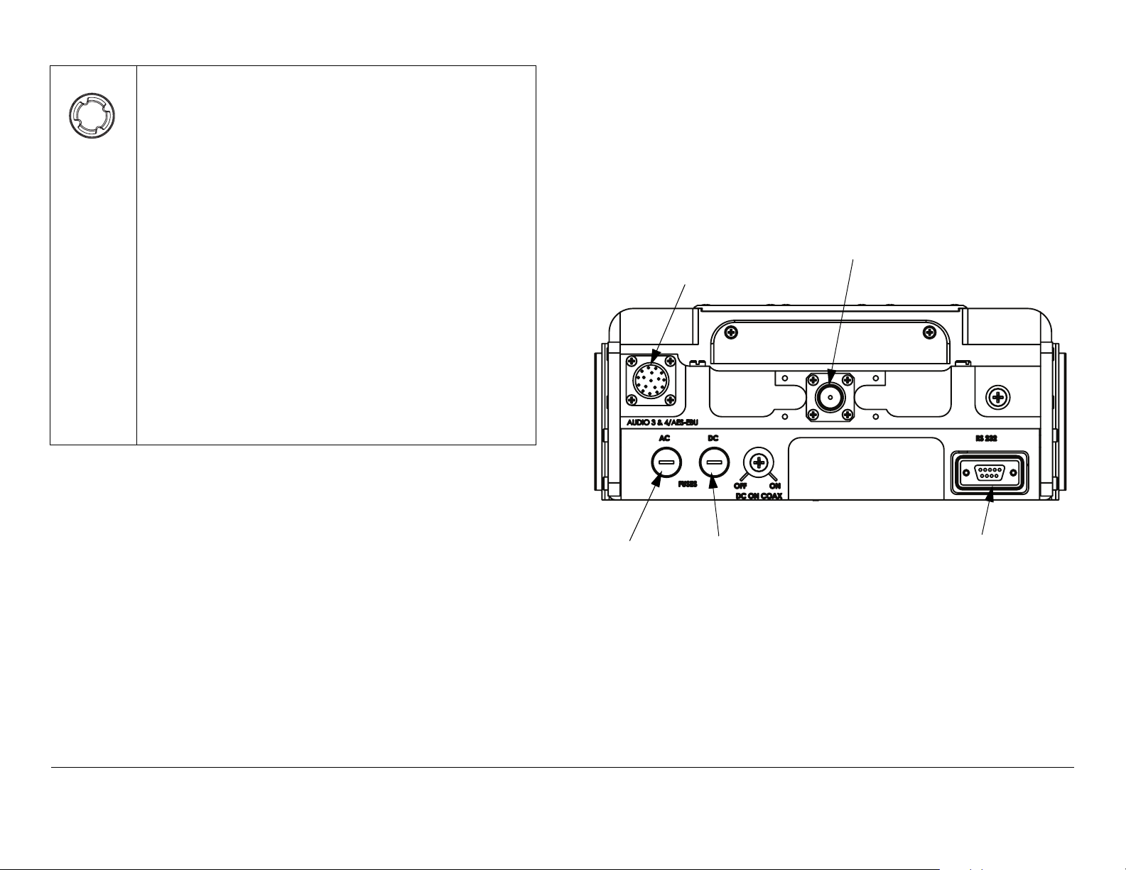
panel are shown in Figure 3-2.
AUDIO 3 & 4/AES-EBU Connector The rear panel 10-pin
female connector receives balanced audio inputs for audio
channels 3 and 4.
Figure 3-2: PTX-PRO Rear Panel Controls, Indicators, and Connectors
AUDIO 3 & 4/
AES-EBU
RF Output
Connector
Connector
AC Fuse
DC Fuse
RS 232
Connector
PWR Switch The front panel PWR (power) switch controls
application of AC or DC power to the PTX-PRO.
AC/DC Power Connector The front panel AC/DC power
connector mounted on the front panel of the unit allows the PTXPRO to operate on external AC or DC power sources.
3.2.2 Rear Panel Connectors and Fuses
Controls, fuses, and connectors contained on the PTX-PRO rear
Routine Operation 3-4PTX-PRO User and Technical Manual
RF Output Type “N” Connector The rear panel 50 ohm, type
“N”, female connector provides the RF output to the transmitting
antenna. The universal type “N” connector allows the PTX-PRO
to easily be used for emergency restoration of a StudioTransmitter Link (STL) or Inter-City Relay (ICR) link.
AC Fuse The rear panel AC fuse provides AC input power
protection for units used with AC power sources.
DC Fuse The rear panel DC fuse provides DC input power
protection for units used with DC power sources.
RS 232 DB-9 Connector The RS 232 DB-9 connector provides
connections for factory test or to a Microsoft Windows-based PC
when using the Configurator software. The connector also
provides connections for Wayside data.
3.3 Preparing for Operation
Each installation or deployment will have its own specific tasks
according to the application and the installed hardware.
Connect the power cable to the power source.
If you are unsure of the power requirements or the
connections, refer to the “Installation” Chapter on
page 6-1.
3. Verify the power source is turned on.
4. Set the front panel PWR switch to on ( I ).
5. The normal power-up sequence is as follows:
-The PWR LED above the PWR switch should
illuminate and should quickly change colors from red,
to green, to amber, to green, and should remain green.
3.3.1 Portable Deployment - Typical
For portable applications where the PTX-PRO will be moved
from place to place and set up each time, the system will
typically be mounted on an MRC Quick Release Mount for easy
attachment to an MRC tripod. Other mounts are also available.
For additional information, refer to the “Installation” Chapter on
page 6-1.
3.3.2 Powering the PTX-PRO Transmitter
The procedures required to power up and power down the PTXPRO are contained in the following steps.
Power Up
1. Verify the power cable is properly connected to the
PTX-PRO front panel power connector.
2. Verify all front and rear panel cables and connectors
have been properly connected.
If you are unsure of the connections, refer to the
“Installation” Chapter on page 6-1.
- The alphanumeric display should light up and quickly
display a self-test screen, then the version of the
firmware, and finally the Main screen.
- Some typical screens are shown in Figure 3-3. Exact
screens displayed will vary.
- The PTX-PRO will typically power up using the last
settings in use when power was turned off.
- If the PTX-PRO does not power up normally, refer to
the “Troubleshooting” Chapter on page 4-1.
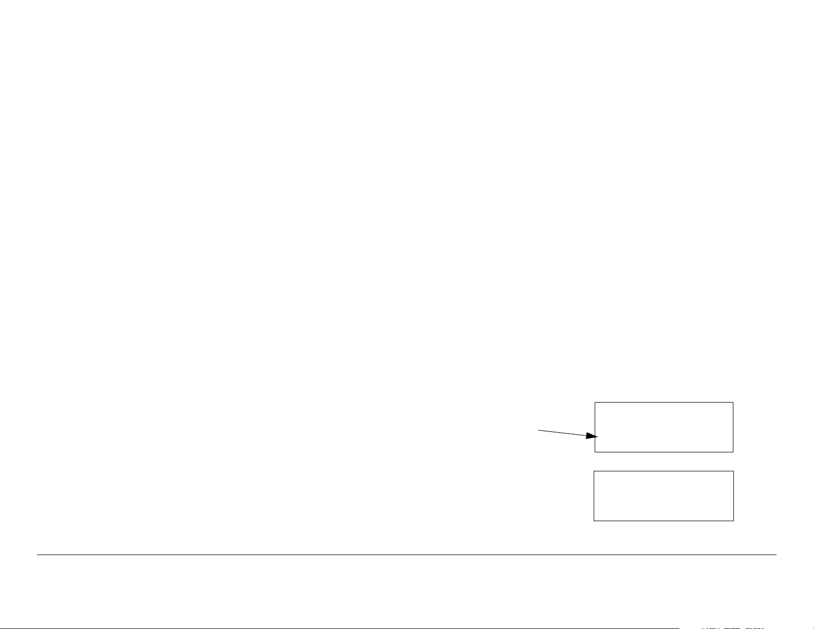
Figure 3-3: Typical PTX-PRO Power Up Screen
Firmware
Version
PTX-PRO
V X.X.X
Preset #1
Main Screen
0.00W C 3
Routine Operation 3-5PTX-PRO User and Technical Manual
Power Down
1. Set the PWR switch to off ( 0 ).
2. Set the power source power to off.
3.4 Using the Display Screens
Accessing the Control Screen You can access the Control
screen at any time by turning the control switch counterclockwise (ccw).
Default to Main Screen If you do not turn or press the control
switch within a period of approximately 7 seconds, the display
will default to the Main screen.
As you use the PTX-PRO, you will interact extensively with the
screens displayed on the alphanumeric display. Following are
some points to make this easier.
Main Screen The Main screen is your starting point for
navigating through the Monitor and Control screens. The Main
screen provides the current values of the Preset selected and
the selected Preset output power level.
When the PTX-PRO completes its power-up sequence, the Main
screen will be displayed. A typical Main screen is shown in
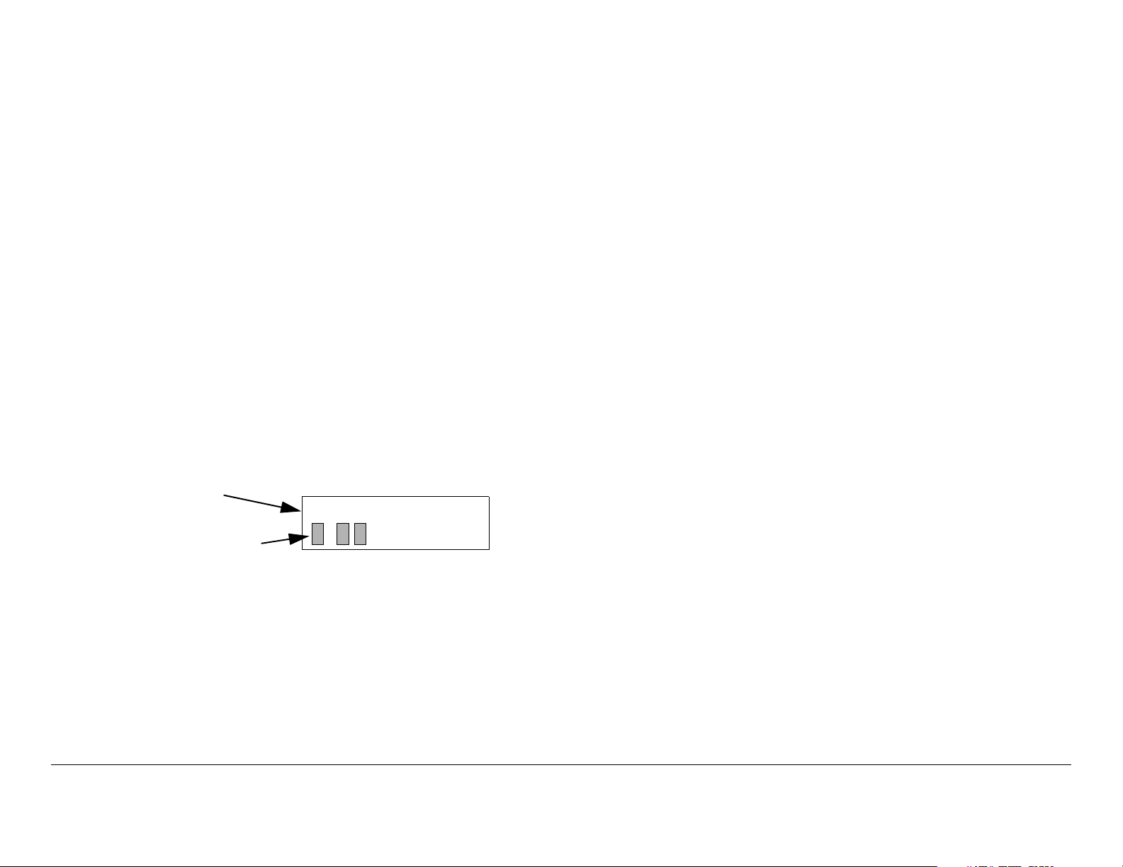
Figure 3-4.
Figure 3-4: Main Screen - Typical
Currently
Selected
Preset
Output Power
Level
Accessing the Main Screen You can access the Main screen
at any time by scrolling to the end of the screens you are viewing
(either Monitor or Control). Your next click of the control switch
will bring up the Main screen.
Accessing the Monitor Screen You can access the Monitor
screen at any time by turning the control switch clockwise (cw).
Preset 3
. W
If you turn the control switch within those 7 seconds, you will
continue scrolling within that set of screens (Monitor or Control).
3.5 PTX-PRO Monitoring Operations
The PTX-PRO Presets are set to five possible modes of
operation. These operating modes are established using the
Configurator software. Operating mode options displayed on the
Monitor screens are indicated below in bold fonts. Operating
mode options available via the Configurator software are as
follows:
• MPEG/COFDM IF Out (COFDM mode)
• COFDM Only - ASI In (ASI/SDI In mode)
• External 70MHz IF In (Ext IF Input mode)
• LMS-T (Terrestrial) (LMS-T mode)
Once the PTX-PRO is set up and powered up, you will be able to
check its configuration and monitor its operation. When
configuration settings are established for the individual Presets
using the Configurator software, the individual Preset operating
modes should be recorded for quick reference.
The following sections describe how to use the Monitor screens.
Here are the tasks described:
Routine Operation 3-6PTX-PRO User and Technical Manual
Topic Page
Using the Monitor Screens in COFDM Mode 3-7
Using the Monitor Screens in ASI/SDI Input Mode 3-7
Using the Monitor Screens in Ext IF Input Mode 3-7
Using the Monitor Screens in LMS-T Mode 3-7
3.5.1 Using the Monitor Screens in COFDM Mode
When the PTX-PRO is operating in the COFDM mode, 70 MHz
COFDM IF output from the internal COFDM/MPEG board is
supplied to the RF output and MONITOR connectors. See
Figure 3-5 on page 3-8 for the COFDM Monitor Menu Map.
3.5.2 Using the Monitor Screens in ASI/SDI Input Mode
When the PTX-PRO is operating in the ASI In mode, the internal
MPEG encoder is bypassed and an externally supplied ASI
stream is routed to the MONITOR and RF output connectors.
See Figure 3-6 on page 3-9 for the ASI In Menu Map.
utilizes a single carrier modulator and supplies a configurable
LMV-S signal to the transmitter RF output and MONITOR
connectors.
This mode is operational for QPSK and 16 QAM modulation
formats. See Figure 3-8 on page 3-11 for the LMS-T Monitor
Menu Map.
3.5.3 Using the Monitor Screens in Ext IF Input Mode
When the PTX-PRO is operating in the Ext. IF In mode, the 70
MHz IF input signal to the SIGNAL INPUT connector is routed
through the transmitter. See Figure 3-7 on page 3-10 for the Ext.
IF Monitor Map.
3.5.4 Using the Monitor Screens in LMS-T Mode
When the PTX-PRO is operating in the LMS-T mode, this mode
Routine Operation 3-7PTX-PRO User and Technical Manual
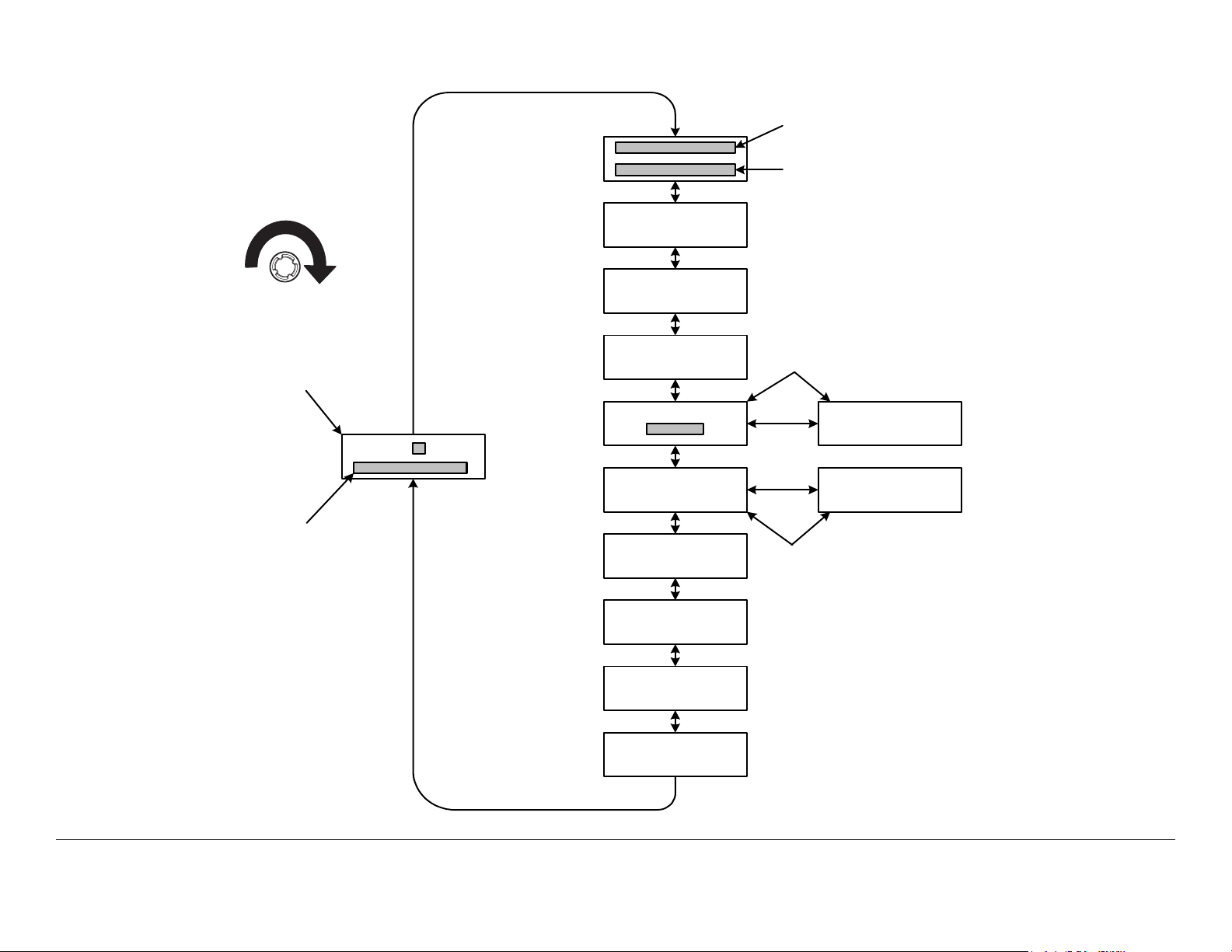
Figure 3-5: COFDM Monitor Menu Map - Typical
This line will display Frequency
for Preset selected.
Monitor Menu Access:
TURN Control Switch
cw to view Monitor
options.
Main Screen
Preset
Displays power level
and Channel number.
TX Attn
0.0dB
Band
13 GHz
Mode
COFDM
QPSK 8MHz
ASI: Mb
NTSC NoPdstl
Vid In 4:2:0
Video Delay
Normal
This line will display the sam e
information as the Main
Screen.
Displays will alternately
appear.
COQPSK 8MHz
FE1/2 GI1/8
No Video
Vid In 4:2:0
Displays will alternately
appear if no video is present.
MPEG AudioA
AESEBU Streo
MPEG AudioB
AESEBU Streo
Error Page
NOTE All Monitor Screens
revert to the Main Screen
after 7 seconds of
inactivity.
Routine Operation 3-8PTX-PRO User and Technical Manual
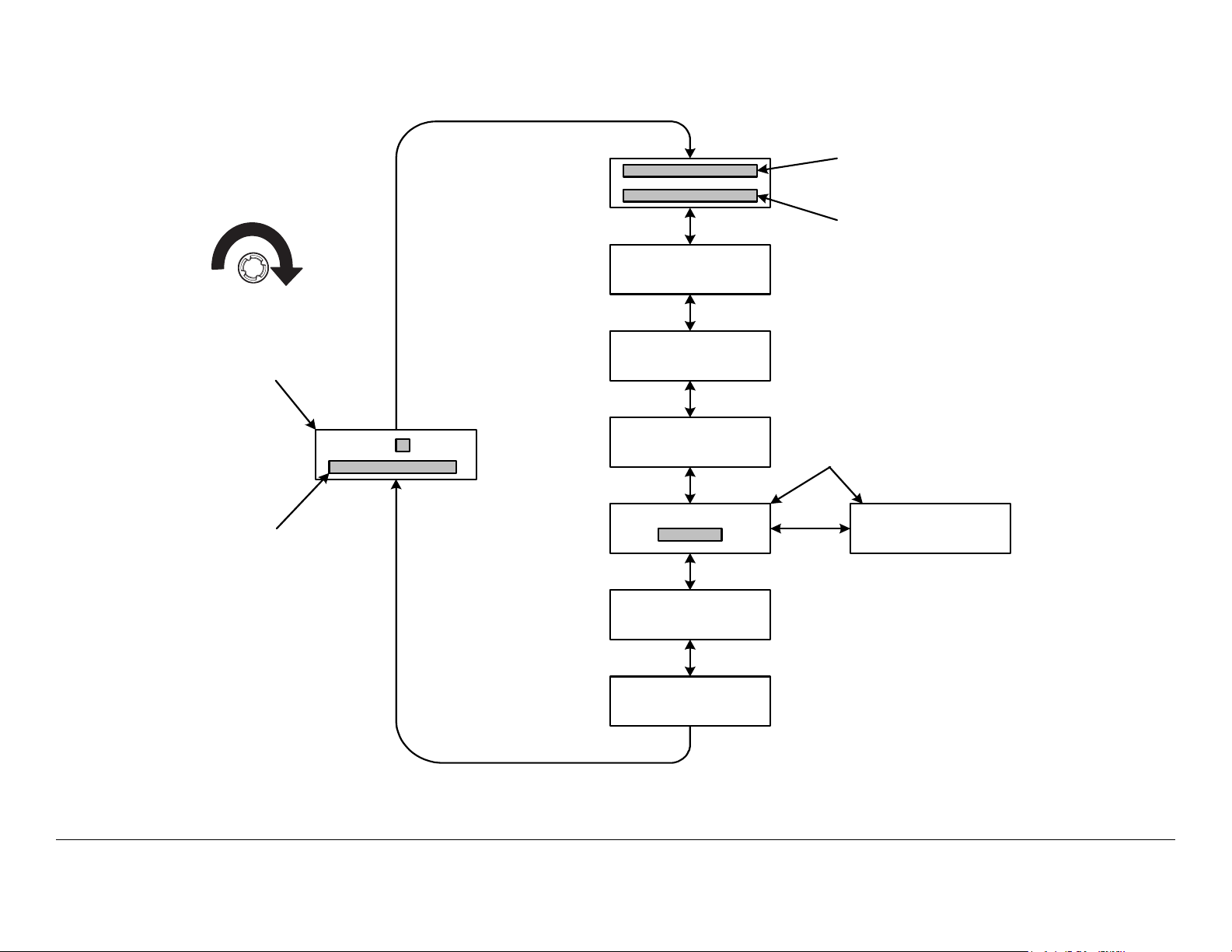
Figure 3-6: ASI/SDI Input Monitor Map - Typical
Monitor Menu Access:
TURN Control Switch
cw to view Monitor
options.
Main Screen
Preset
Displays power level
and Channel number.
TX Attn
0.0dB
Band
13 GHz
Mode
ASI/SDI In
QPSK 8MHz
ASI: Mb
IF CW OFF
This line will display Frequency
for Preset selected.
This line will display the same
inform ation as the Main
Screen.
Displays will alternately
appear.
COQPSK 8MHz
FE1/2 GI1/8
NOTE All Monitor Screens
revert to the Main Screen
after 7 seconds of
inactivity.
Error Page
Routine Operation 3-9PTX-PRO User and Technical Manual
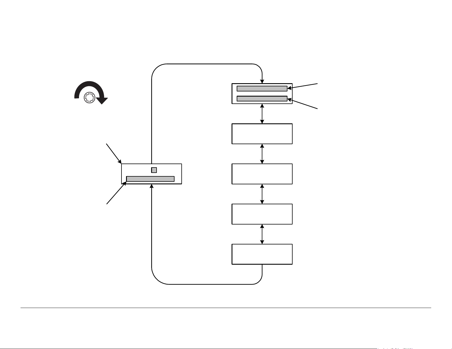
Figure 3-7: Ext IF Input Monitor Map - Typical
Monitor Menu Access:
TURN Control Switch
cw to view Monitor
options.
Main Screen
Preset
TX Attn
0.0dB
Band
13 GHz
This line will display Frequency
for Preset selected.
This line will display the same
information as the Main
Screen.
NOTE All Monitor Screens
revert to the Main Screen
after 7 seconds of
inactivity.
Displays power level
and Channel number.
Mode
Ext IF Input
Error Page
Routine Operation 3-10PTX-PRO User and Technical Manual
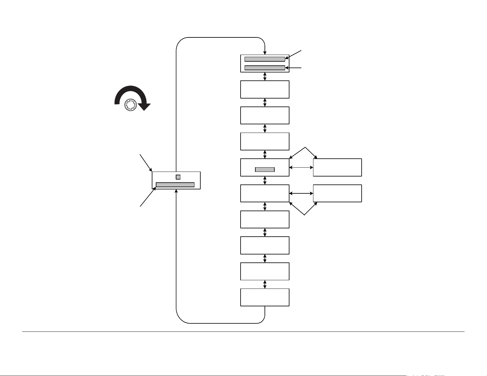
Figure 3-8: LMS-T Monitor Menu Map
This line will display Frequency
for Preset selected.
Monitor Menu Access:
TURN Control Switch
cw to view Monitor
options.
Main Screen
Preset
Displays power level
and Channel number.
TX Attn
0.0dB
Band
13 GHz
Mode
LMS-T
QPSK 10MHz
ASI: Mb
NTSC NoPdstl
Vid In 4:2:0
Video Delay
Normal
MPEG AudioA
AESEBU Streo
MPEG AudioB
AESEBU Streo
This line will display the same
information as the Main
Screen.
Displays will alternately
appear.
QPSK 10MHz
FE2/3 GI1/8
No Video
Vid In 4:2:0
Displays will alternately
appear if no video is present.
NOTE All Monitor Screens
revert to the Main Screen
after 7 seconds of
inactivity.
Error Page
Routine Operation 3-11PTX-PRO User and Technical Manual

3.6 PTX-PRO Control Operations
This section describes how to configure your PTX-PRO using
the front panel control switch. Turning the front panel control
switch counterclockwise (ccw) controls transmitter functions
including changing Presets, changing the video input (VI) mode,
changing SD or HD video inputs, changing color bar settings,
and setting RF attenuation levels.
See ”Front Panel vs. Configurator Settings” on page 3-14 for a
summary of settings that can be changed using the front panel
control switch and which are made using the Configurator
software. See Figure 3-9 on page 3-13 for the Control Menu
Map.
Routine Operation 3-12PTX-PRO User and Technical Manual
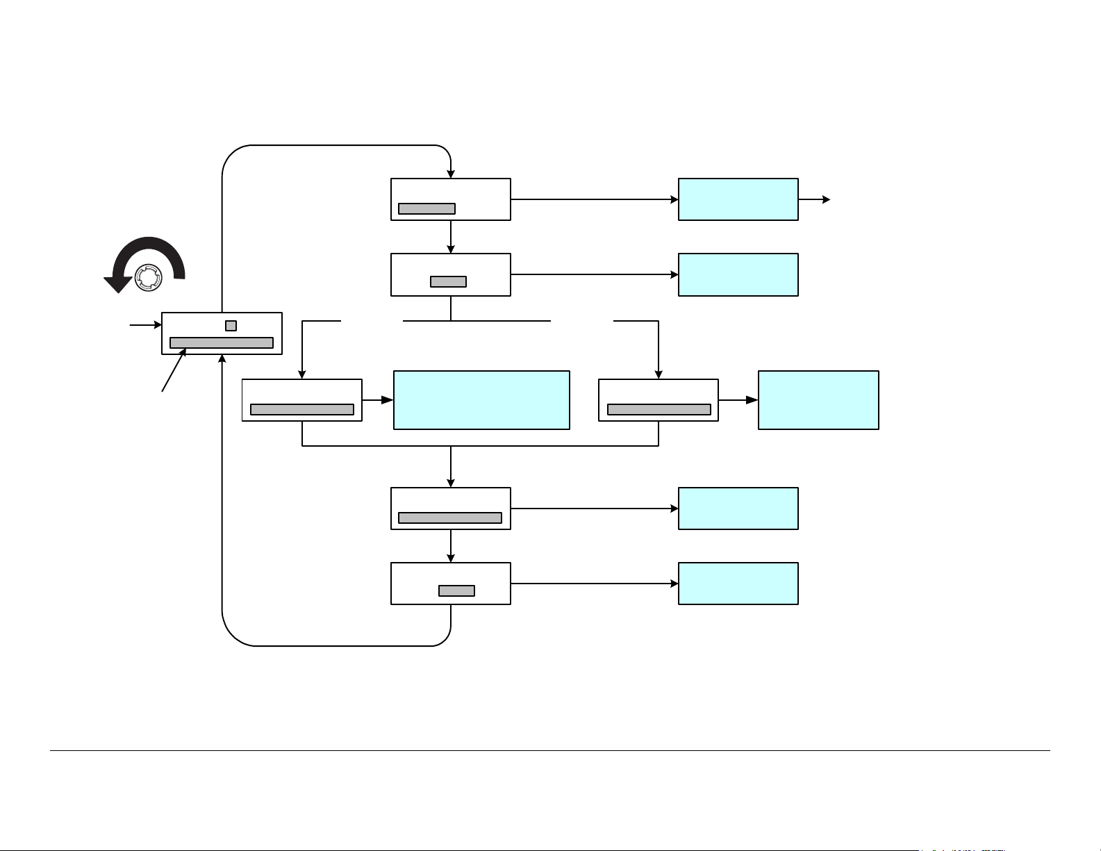
Figure 3-9: Control Menu Map
Control Menu Access:
TURN Control Switch
ccw and PRESS to
activate.
Main
Screen
Preset
Displays power level
and Channel number.
NOTE
The Chng VI Mode, Chng
SD/HD VI, and Chng Clr
Bar Control Screens are
present only if the Preset
operating mode is COFDM
or LMS-T.
(SD Option) (HD Option)
1) PRESS to activate
2) TURN to change
3) PRESS to select
Chng SD VI
NOTE
All Control Screens
revert to the Main
Screen after 7 seconds
of inactivity.
1) PRESS to activate
2) TURN to change
Chng Preset
SD Mode only
3) PRESS to select
1) PRESS to activate
2) TURN to change
3) PRESS to select
Select 525 Line SDI, NTSC,
or NTSC NoPdstl (NTSC) or
625 Line SDI, PAL In, PAL M In,
or PAL N In (PAL)
1) PRESS to activate
2) TURN to change
Chng Clr Bar
Set TX Attn
3) PRESS to select
1) PRESS to activate
2) TURN to change
3) PRESS to select
Attn:
Chng HD VI
Select Preset 1
thru Preset 9
Select SD or HD
1) PRESS to activate
2) TURN to change
3) PRESS to select
Select 1080i30,
1080i29, 1080i25,
720p60, 720p59, or
720p50
Select Auto Gen,
Auto Standby, ON,
or OFF
Select 0 to -19
dB Attenuation
Returns to Main
Screen after
PRESS to select
NOTE
The HD option may only be selected if
your PTX-PRO contains the licensed,
factory-enabled HD option. If the
licensed HD option is not present in
your radio, SD Mode Only will be
displayed in lieu of Chng VI Mode
and the video input mode cannot be
changed.
Routine Operation 3-13PTX-PRO User and Technical Manual
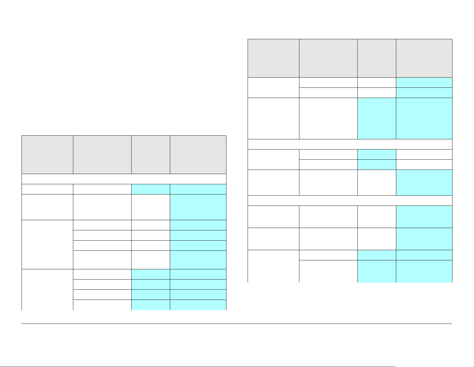
3.7 Front Panel vs. Configurator
Table 3-1: Front Panel vs. Configuration Setting (Continued)
Settings
The design of the PTX-PRO and the Configurator software
makes commonly available settings accessible from the PTXPRO front panel switches and alphanumeric display and more
advanced settings accessible through the Configurator software.
A summary of settings that can be controlled by each method is
shown in Table 3-1.
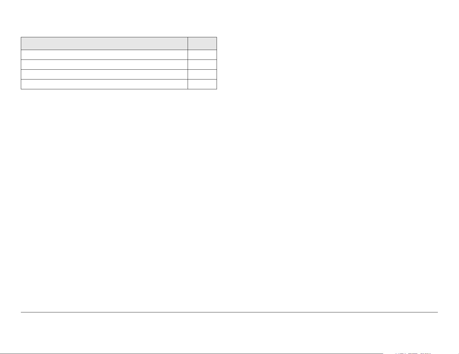
Table 3-1: Front Panel vs. Configuration Setting
Set
Parameter
Presets
Preset in use 1, 2,... 9
Preset text Any 12
Operation
Mode
(Special
license
required for
LMS-T)
Color Bars • ON
Available
alphanumeric
characters
•COFDM
• ASI In
• Ext. IF In
•LMS-T
•OFF
Settings
Using
Control
Switches
✔ ✔
✔ ✔
✔ ✔
Set Using
Configurator
✔
✔
✔
✔
✔
Set
Parameter
Available
Settings
Using
Control
Set Using
Configurator
Switches
IF/CW Tone • ON ✔
•OFF
Variable
Voltage
Attenuation
(TX VVA)
(Back Off)
Channels
Channel &
Offset in use
Channel &
Offset
Frequencies
MPEG
Service
Name
Network
Name
Video Input
Mode
• Variable (0 to
-19 dB in 1
dB steps)
• 1 thru 22
•+, 0, -
13 GHz band
• Any eight
alphanumeric
characters
• Any eight
alphanumeric
characters
•SD
• HD (Special
license
required)
✔ ✔
✔
✔
✔ ✔
✔ ✔
✔
✔
✔
✔
•Auto
• Standby
✔ ✔
✔ ✔
Routine Operation 3-14PTX-PRO User and Technical Manual
 Loading...