

Microwave Radio Communications ODU7ATXAD, ODU2ATXADH Users Manual
MTX5000
Transmitter System
User and Technical Manual
Manual Part No. 400591-1 Rev. A June 2009


NOTE TO USER
Overview
The MTX5000 Transmitter System (MTX5000 ) is a state-of-theart transmitter system. The MTX5000 Indoor Unit (IDU) cont ains
a central proce ssor used to cont rol all function s and operations
of the system. To avoid potential software hang-ups or software
corruption, please read and follow the guidelines contained in
the following paragraphs.
Avoid Potential Operational
Problems
Information contained in the following paragraphs identify
potential problems that can be avoided by reading and following
the operating procedures provided in this manual.
To avoid potential operational problems, please review the
information contained in the “Routine Operation” Ch ap ter on
page 3-1. The Routine Operation Chap ter cont ains step -by-step
procedures that, when performed correctly, will eliminate
potential problems that could be caused by operator error or by
lack of experience with the MTX5000 system.
Radio Unable to Transmit or Generally Unstable
• If the radio is unable to transmit or is generally unstable,
perform “Select Preset” on page 3-24 to select or re-
select the proper Preset. Then verify proper transmitter
operation by transmitting and receiving.
• If the radio remains unstable, it may be necessary to cycle
power off and on. See ”Powering the MTX5000 System”
on page 3-7 to power down and power up the MTX5000.
Always wait a minimum of 10 seconds between
powering the radio down and then powering the radio
up again.
• After cycling power to off and back to on, perform “Select
Preset” on page 3-24 to select the proper Preset. Then
verify proper transmitter operation by transmitting and
receiving.
• If the radio is still unable to transmit or remains unstable,
contact MRC Technical Support for assistance.
Improper Power Up/Power Down
If the radio is unable to transmit, is unstable, or if the software
appears to be corrupted, the Preset may have been selected or
changed too soon after power was applied or the wrong Preset
was selected.
• Always wait a minimum of 5 seconds after the Main
screen is displayed following power up before selecting a
Preset.
• If the wrong Preset is selected, you must wait a minimum
of 5 seconds before attempting to select another Preset.
Failure to wait 5 seconds minimum between Preset
selections will cause software hang-ups.
If the radio is unable to transmit, is unstable, or if the software
appears to be corrupted, power to the radio may have been
removed and reapplied too quickly.
The MTX5000 central processor req uires a minimum of 10
seconds to properly shutdown to avoid possible software
corruption.
NOTE TO USER iMTX5000 User and Technical Manual

• Software corruption can occur if the external input power
to the radio was momentarily lost and was then reapplied
without waiting a mini mum o f 10 seconds betwee n lo ss of
power and reapplicat ion of input power.
• If the software is corrupted and the Main screen is not
displayed, contact MRC Technical Support for assistance.
Radio State Incorrect
• The problem may also occur if the power switch was
pressed to off and back to on without waiting a minimum
of 10 seconds.
• To avoid problems, always wait a minimum of 10
seconds between removal or loss of power and
reapplication of power to the radio.
• The problem may also occur if the progress bar was
displayed when power was removed from the radio.
Always ensure the progress bar is not displayed on
the color LCD display panel when power is removed
from the radio.
If this problem has occurred, press the power switch to off, wait
10 seconds minimum, and press the power switch to on. The
internal processor will attempt to perform a self-recovery of the
software.
• During the software recovery attempt, a progress bar will
be displayed on the color LCD display panel indicating the
progress of the process. This progress bar will take more
time to reach 100% than during a normal power up.
• Do not become impatient during the software
recovery process due to the time it may take for
recovery. Do not remove and reapply power while the
progress bar is displayed during the software selfrecovery process. Software corruption will occur!
• When the power up is complete and the Main screen is
displayed on the color LCD display panel, verify proper
transmitter op eration by trans m itting and receiv ing.
If the radio state is incorrect, th e correct Preset may not have
been selected. Select the proper Preset per “Select Preset” on
page 3-24.
PA Voltage Adjust Setup Software Hang-up
When performing “Perform PA Voltage Adjust Setup” on page 3-
44, ensure the Outdoor Unit (ODU) is properly connected to the
IDU. If the ODU is not connected to the IDU and you attempt to
perform this procedure, the software will hang up.
• To avoid softwa re hang-up, always ensure the ODU is
connected to the IDU when performing the P A V oltage
Adjust Setup procedure.
• Check the Main screen ODU status indicator. If a major
fault exists in the ODU, do not perform the PA Voltage
Adjust Setup pr ocedure until the fault has been corrected
or until the ODU is c onnected to the IDU.
• If the ODU is not connected to the IDU or if the ODU has
suffered a failure, the P A Voltage Adjust Setup Screen will
remain displayed on th e co lor L CD displ ay p anel if th e PA
Voltage Adjust Setup screen Start option button is
selected.
If the software hangs up due to the ODU not being connected to
the IDU or if the ODU has failed, perform the following:
• Press the power switch to off.
• Connect the ODU to the IDU or go to “Troubleshooting”
on page 4-1 to correct the fault.
NOTE TO USER iiMTX5000 User and Technical Manual

• Press the power switch to on, perform “Select Preset” on
page 3-24 to select the proper Preset.
to perform “Select Preset” on page 3-24. Then verify
proper transmitter operation by transmitting and receiving.
• “Perform PA V olt age Adjust S etup” on page 3-44 and then
verify proper transmitter operation by transmitting and
receiving.
RF Levels Too High
If the transmitted RF levels are too high, “Perform RF Level
Adjust” on page 3-49.
Software Recovery
If the software becomes corrupted, the MTX5000 IDU will
attempt to self-recover the software. During the software selfrecovery, the previously configured parameters may be
recovered - not th e late st pa rameters. This m ay happ en if a fault
occurs when installing software updates.
If the software becomes corrupted, pr ess the power switch to of f,
wait 10 seconds minimum, and press the power switch to on.
The internal processor will attempt to perfor m a self-recovery of
the software.
• During the software recovery attempt, a progress bar will
be displayed on the color LCD display panel indicating the
progress of the recovery process. This progress bar may
take considerably more time to reach 100% than during a
normal power up.
• Do not become impatient during the software
recovery process due to the time it may take for
recovery. Do not remove and reapply power while the
progress bar is displayed during the software
recovery process. Software corruption will occur!
If the software is no longer corrupted, perform “Firmware
Update” on page 5-114 to verify that you have the latest sof tware
installed in your MTX5000 IDU. Update the software, as
required.
If the softw are i s corrupt ed o r i f the Ma in sc reen is not displ ayed,
contact MRC Technical Support for assistance.
Color Bar Generator Operations
All MTX5000 Indoor Units (IDU) contain a built-in digital Color
Bar Generator (CBG ) as standard equipment. The IDU is also
available with an optional analog CBG. Potential operator
problems can occ ur when using the op tional analog CBG or the
built-in digital CBG.
Potential operator-induced problems may include the following:
• Selection of the CBG On operating mode during test,
troubleshooting, or CBG setup and failure to select the
Off, A Gen, or A Stb y operating mode for normal
operation whe n test, troubles hooting, or CBG setup is
completed.
• Selection of the CBG On, A G en, or A Stby operating
mode when the optional Analog Color Bar Generator is
not installed in the MTX5000 IDU.
To avoid potential operator problems that can impact operation
of the MTX5000 System, the following information is provided:
• The optional analog CBG and the digital CBG both
include Off, On, A Gen (Auto Generated), or A Stby
(Auto Standby) operating mode options.
• When the power up is complete and the Main screen is
displayed on the color LCD display panel, you may need
NOTE TO USER iiiMTX5000 User and Technical Manual
• The CBG mode should only be set to the On operating
mode for test, troubleshooting, or for setup of the

applicable Color Bar Gene rator.
• During normal operation, the CBG Off, A Gen, or A Stby
operating mode must be selected for proper operation
and video transmission.
• CBG operating modes are not Preset-specific or modespecific. If your IDU contains the optional analog CBG
and you select the Off, A Gen, or A Stby operating m ode
for an analog Preset, the selected option is applicable for
all analog Presets, as well as for all digital Presets.
• If the CBG On operating mode is selected, the output of
the MTX5000 IDU will be color bars only, not video,
regardless if an analog or a digital Pre set is selected.
When color bars are set to On (enabled), color bars take
priority over all analog and digital Preset settings.
• If the IDU output consists of color bars only, please verify
that the analog and/or digital CBG operation mode is not
set to On before you call customer service. The problem
may be nothing more than having selected the On
operating mode.
Perform “Select Color B ar Gene rator Mode” on p age 3-52
to select the Off, A Gen, or A Stby operating mode.
• It is possible to select analog CBG options if you do no t
have the optional CBG installed in your MTX5000 IDU,
but the options are not active and will result in
transmission problems.
• Be careful when setting CBG options if you do not
have the optional analog CBG installed.
• If you attempt to set the CBG operating mode to On, A
Gen, or A Stby and you do not have the optional analog
CBG installed in your MTX5000 IDU, you will have a blank
screen displayed for analog Presets. Before calling
Customer Service, please veri fy that the analog CBG
operating mode has not been set to On.
Go to “Select Color Bar Generator Mode” on page 3-52
and select the Off, A Gen, or A Stby operation mode.
• When utilizing a digital Preset with an ASI video input and
the digital CBG option setting is A Gen or A Stby, loss of
the ASI video input will not display color bars or will not
change the MTX5000 IDU operation to standby indicating
loss of the ASI signal. This is normal operation for ASI
video loss.
Using the Color LCD Display Panel Touch Screen
CAUTION
Whenever you use the MTX5000 IDU color LCD display panel
Avoid damage to the color LCD display
panel!
The color LCD display panel touch screen
may be damaged if a sharp, hard-pointed
object, such as a pencil or a pen, is used to
select the displayed optio ns.
Touch screen options must only be selected
using your fingers, a soft-pointed stylus, or
the front panel function keys.
Damage to the color LCD display panel
caused by using a hard-pointed object or
other misuse may void your warranty on
the MTX5000 IDU.
NOTE TO USER ivMTX5000 User and Technical Manual

touch screen to select options, use care to avoid damage.
Sharp-pointed objects or excessive force can render the color
LCD display Panel touch screen inoperable.
Use your fingers, a sof t-pointed stylu s, or th e front p anel functi on
keys to select the displayed options. A cotton swab works very
well as a soft-pointed stylus.
Remote Location Operations
It is highly recommended that remote operations be performed
using a Microsoft Windows-based PC that meets the following
requirements:
• Microsoft Windows XP Operating System with SP2
• 1.2 GHz processor
• 500 MB of system memory
• 1.0 Gb of free hard disk space
• Super VGA 800 x 600 pixels
• Internet Explorer 7.0 or later
display panel appe ars to be operating very slowly or h as locked
up completely, disconnect the Ethernet cable from the
ETHERNET connector.
This should free up the color LCD display Panel and the IDU
should resume operating properly.
Notes
Remote location operations must be performed using
Internet Explorer 7.0 or later.
Note
When operating in the remote mode, if the web
page on the PC displa y should become blank when
switching between option tabs, select the web
browser refresh option. The correct screen will
then be displayed
Ethernet Connections
If you are connected to the Ethernet via the IDU rear panel
ETHERNET RJ45 connector and you find that the color LCD
NOTE TO USER vMTX5000 User and Technical Manual

NOTE TO USER viMTX5000 User and Technical Manual

NOTE TO USER viiMTX5000 User and Technical Manual

NOTE TO USER viiiMTX5000 User and Technical Manual

Notices
Notices
Microsoft®, Windows®, and In ternet Explorer ® are registered
trademarks of Microsoft Corporation in the United States and/or
other countries.
About This Manual
Part number 400591-1
Revision A June 2009
MTX5000 Transmitter System (MTX5000)
Copyright
The information cont ain ed in thi s manual r emains th e proper ty of
Microwave Radio Comm unications ( MRC) and may not b e used,
disclosed, or reproduced in any form whatsoever, without the
prior written consent of MRC.
MRC reserves the right to make changes to equipment and
specifications of the product des cribed in th is manual at any time
without notice and without obligation to notify a ny person of such
changes.
© 2009 Microwave Radio Communications
Microwave Radio Commu nications
101 Billerica Avenue - Bldg. 6
North Billerica, MA 01862-1256 USA
TEL: 800.490.5700
+1.978.671.5700
Grainger® is a registered trademark of W.W. Grainger, Inc., in
the United States and other countries.
McMaster® is a registered tradema r k of McMaster-Carr Supply
Company in the United States and other coun tries.
Do It Best ® is a registered trademark of DoitBest.com or its
affiliate, Do It Best Corp., in the United States and other
countries.
Propriet ary Material
The information and design contained within this manual was
originated by and is the propert y of MRC. MRC reserves all
patent proprietary design, manufacturing, reproduction use, and
sales rights thereto, and to any articles disclosed therein, except
to the extent rights are expressly granted to others. The
foregoing does not apply to vendor proprietary parts.
MRC has made every effort to ensure the accuracy of the
material contained in this manual at the time of printing. As
specifications, equ ipment, and this manual are subj ect to change
without notice, MRC assumes no responsibility or liab ility
whatsoever for any er rors or inaccuracies that m ay appear in this
manual or for any decisions based on its use. This manual is
supplied for informat i on pur p oses on ly and shoul d not be
construed as a commitment by MRC.
Printed in U.S.A.
The Microwave Radio Communications and Vislink trademarks
and other trademarks are registered trademarks in the United
States and/or other countries.
Quality Certification
Microwave Radio C o mm u ni cati o ns i s cer ti fi e d to ISO 9001:2000.
Notices Notices-iMTX5000 User and Technical Manual

Changes or modificati ons not expressly approved by MRC could
void the user’s authority to operate the equipment.
General Safety Information
The following safety requirements, as well as local site
requirements and regulations, must be observed by personnel
operating and mai ntaining th e equipment cover ed by this manual
to ensure awareness of potential hazards.
WARNING - RF Power Hazard
be greatly enhanced.
In this situation, a certain dist a nce from the radi ato r is to be
maintained. Calculations need to be performed to understand
what that safe margin for exposure is. This is known as the
Maximum Permissible Exposure (MPE) limit.
Note
Hazardous RF radiation limits and recommended
distances may vary by country. Ensure that all
applicable state and federal regulations are
observed when using this transmitter.
High levels of RF pow e r a r e pr e sent in the unit. Exposure to RF
or microwave power can cause burns and may be harmful to
health.
Remove power fro m the unit before disconnecting an y RF cables
and before inspecting damaged cables and/or antennas.
Avoid standing in front of high gain antennas (such as a dish
antenna) and never look into the open end of a waveguide or
cable where RF power ma y be pre sent.
RF Exposure - Safe Working Distances
MRC provides this warning for safety purposes with the intent to
inform the user of the potential hazard to RF exposure. The
following guidelines for safe operation were derived from OET
bulletin 65, August 1997, as recommended by the Federal
Communications Commission (FCC).
The MTX5000 Transmitter System is a mobile transmitter
system designed to provide services to broadcast ENG users
under CFR 74 subpart F and 74.601 TV pickup stations. This
unit, operated without an antenna, will no t cre ate RF energy
Calculations provided are for common antennas often utilized in
the ENG environment. The following formula used is that
suggested by OET 65.
Calculating MPE
EIRP = P * (10 ^ (G / 10)) = (antilog of G/10) * P
P = RF power delivered to the antenna in mW
G = Power gain of t he anten na in the dir ection of intere st relati ve
to an isotropic radiator
R = distance to the center of radiation of the antenna in
centimeters
S = MPE in mW/cm² (milliwatts per square centimeters)
Conversions
dBi to numeric gain = Antilog (dBi/10)
Feet to centimeters = Feet * 30. 48
Centimeters to Feet = cm * .0328
4 π = 12.57
exceeding 1.0 mW/cm2, the FCC limit for exposure. Once
connected to an antenna, the potential for harmful exposure will
Notices Notices-iiMTX5000 User and Technical Manual
User Input
RF power delivered to the antenna = Watts
Antenna gain (referenced to isotropic antenna) = dBi
Distance from the center of radiation = Feet
Calculation steps:
MRC, in accordance with th e requ ireme nt s set for th by the FCC,
provides this information as a guide to the user. It is assumed
that the users of this equipment are licensed and qualified to
operate the equipment per the guidelines and recommendations
contained wi thin the pr oduct user gu ides an d in acco rdan ce with
any FCC rules that may apply.
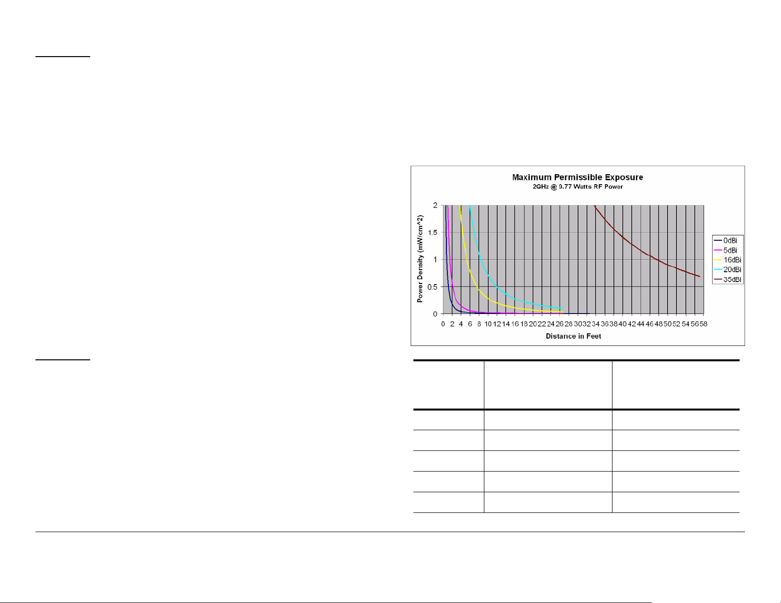
Figure 1 with its corresponding table shows the 2GHz MPE.
1. [P] RF power input. Convert watts to milliwatts = Watts *
1000
2. [G] Antenna gain dBi. Convert to numeric gain = Antilog
(dBi/10)
3. [EIRP] Multiply P * G
4. [R] Convert centimeters to feet = Centimeters * .0328
5. Square R
6. Multiply R² * 4π
7. [S] Divide (R² * 4π) into EIRP
S = Power Density in milliwatts per square centimeters. Note:
At frequencies above 1500 MHz, S must not be greater than 1.
Reference
FCC OET Bulletin 65, August 1997 - Evaluating Compliance with
FCC Guidelines for Human Exposure to Radio Frequency
Electromagnetic Fields
The examples shown in Figure 1 an d Figure 2 are typ ical graphs
for an MRC STRATA Transmitter and show the permissible
exposure distance for various antennas. Graphs and data will
vary, based on the actual transmitter, output power, frequency,
and antenna utilized. One plot provides the p ermissible output
of the transmitter for digital modulation, and the other plot for
analog modulation.
Figure 1: MTX5000 MPE 2GHz
Antenna
Gain (dBi)
0 28 11.02
5 50 19.68
16 177 69.67
20 279 109.81
35 1569 617.56
Minimum Distance from
Antenna (cm)
Minimum Distance
from Antenna (inch)
Notices Notices-iiiMTX5000 User and Technical Manual
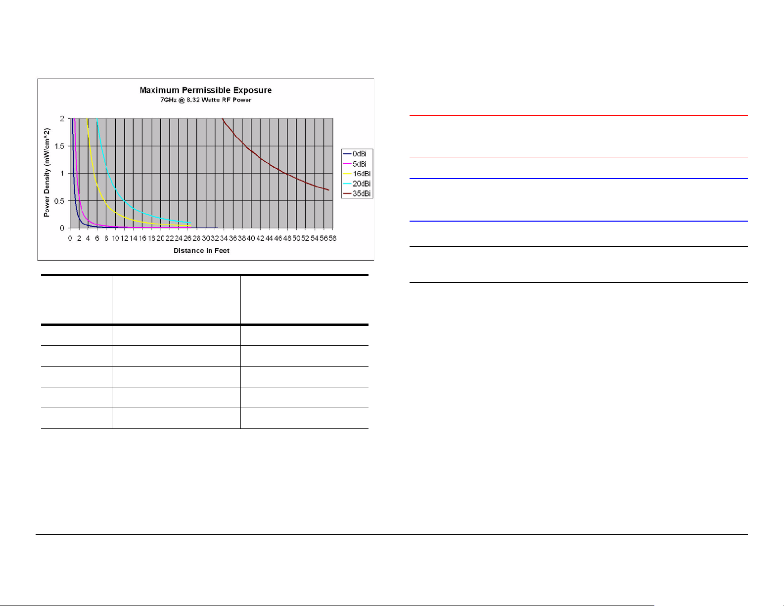
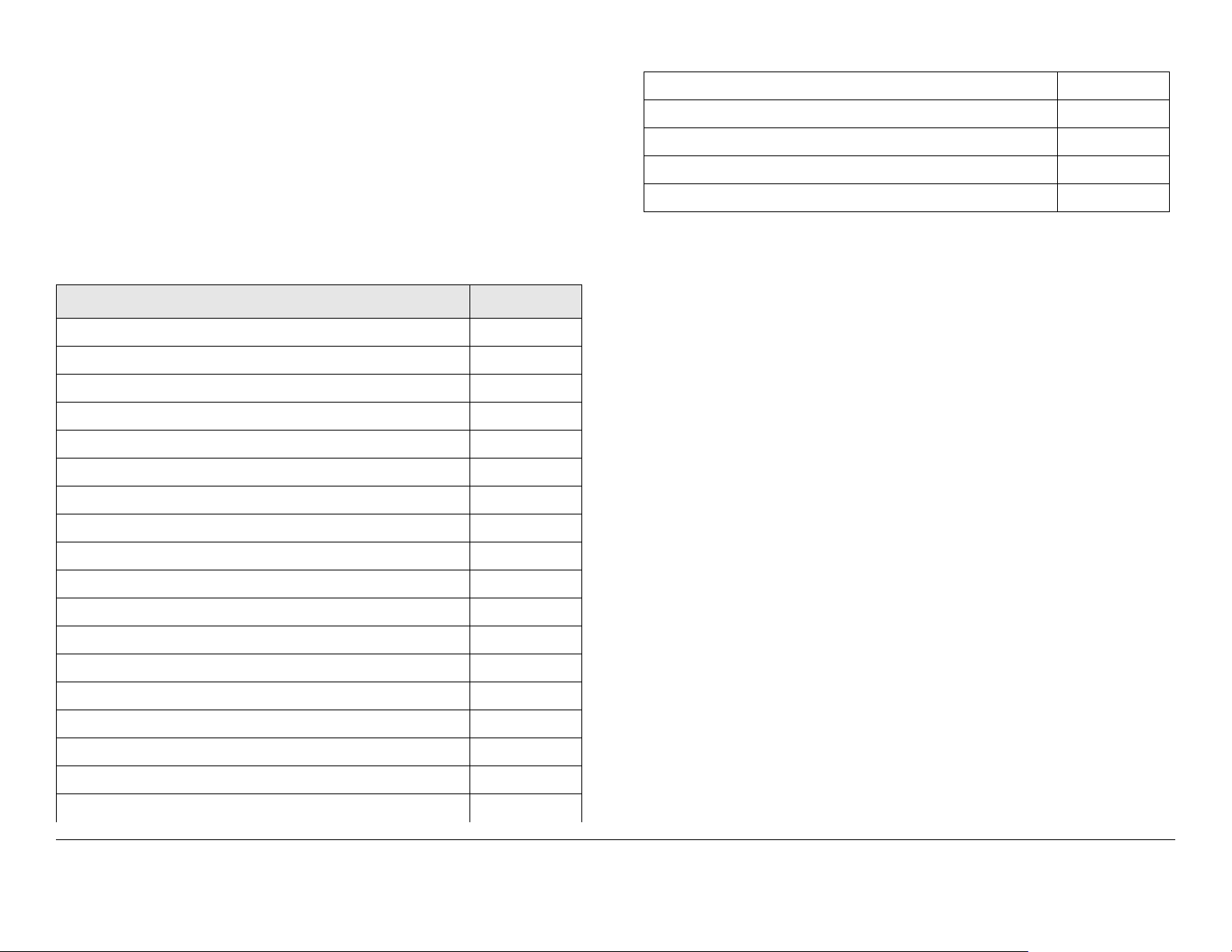
Figure 2 with its corresponding table shows the 7GHz MPE.
Figure 2: MTX5000 MPE 7GHz
Conventions
Pay special attent ion to information mark ed in one of the
followin g ways:
Antenna
Gain (dBi)
0 26 10.23
5 46 18.11
16 163 64.16
20 258 101.55
Minimum Distance from
Antenna (cm)
Minimum D istance
from Antenna (inch)
WARNING
CAUTION
Note
Notes provide additional information to assist you
in using and maintaining the equipment.
Follow WARNINGS closely to prevent
personal injury or death.
Follow CAUTIONS to prevent damage to
the equipment .
35 1448 569.93
Notices Notices-ivMTX5000 User and Technical Manual
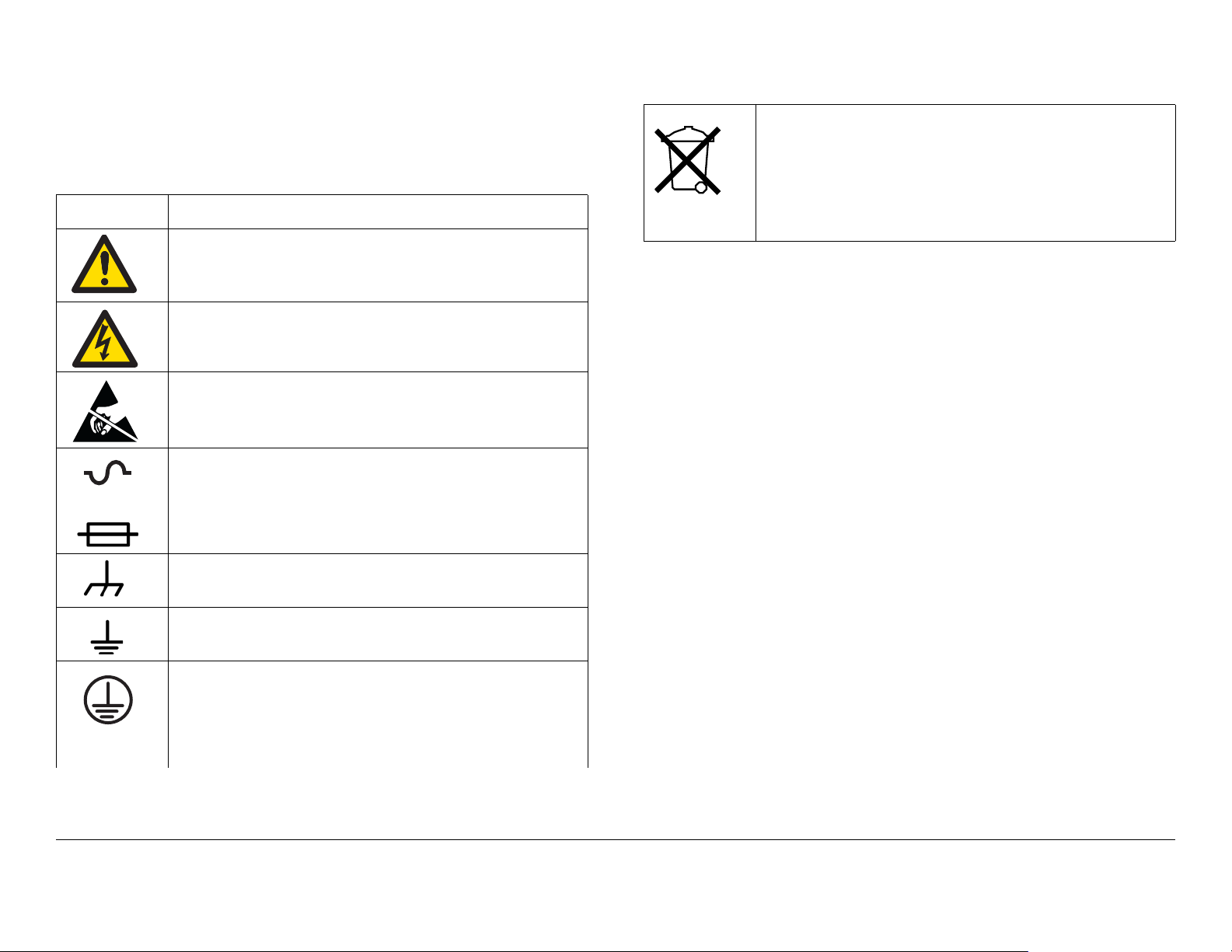
Symbols Used
The following symbols may be used on the equipment or in this
manual:
Symbol Meaning
WARNING: General Warning. Risk of Danger.
WARNING: Risk of Electric Shock.
WARNING: Electrostatic Discharge. Possible
Damage to Equipment.
Fuse - Identifies fuses or their location.
OR
Waste Electrical and Electronic Equipment
(WEEE) - The product must not be disposed of
with other waste at the end of its life cycle. It is
the user’s responsibility to dispose of the waste
equipment by handing it over to a designated
collection point for recycling.
Frame or Chassis Ground - Identifies the frame or
chassis terminal.
Earth Ground - Identifies the earth ground terminal.
Protective Earth Ground - Identifi es any terminal
which is intended for connection to an external
conductor for protection against electri c shock in
case of a fault, or the terminal on a protective earth
electrode.
Notices Notices-vMTX5000 User and Technical Manual

Notices Notices-viMTX5000 User and Technical Manual

Contents
NOTE TO USER - - - - - - - - - - - - - - - - - - - - - - - - - -i
Overview - - - - - - - - - - - - - - - - - - - - - - - - - - - - - - - - - - - i
Avoid Potential Operational Problems - - - - - - - - - - - - - - - i
Radio Unable to Transmit or Genera lly Unstable - - - - - i
Improper Power Up/Power Down- - - - - - - - - - - - - - - - i
Radio State Incorrect - - - - - - - - - - - - - - - - - - - - - - - - ii
PA Voltage Adjust Setup Software Hang-up - - - - - - - - ii
RF Levels Too High - - - - - - - - - - - - - - - - - - - - - - - - - iii
Software Recovery - - - - - - - - - - - - - - - - - - - - - - - - - - iii
Color Bar Generator Op erations - - - - - - - - - - - - - - - - iii
Using the Color LCD Display Panel Touch Screen- - - iv
Remote Location Operat ions - - - - - - - - - - - - - - - - - - - v
Ethernet Connections - - - - - - - - - - - - - - - - - - - - - - - - v
Notices - - - - - - - - - - - - - - - - - - - - - - - - - - - - - - - - i
About This Manual - - - - - - - - - - - - - - - - - - - - - - - - - - - - i
Copyright - - - - - - - - - - - - - - - - - - - - - - - - - - - - - - - - - - - i
Proprietary Material- - - - - - - - - - - - - - - - - - - - - - - - - - - - i
Quality Certification - - - - - - - - - - - - - - - - - - - - - - - - - - - - i
General Safety Informa tion- - - - - - - - - - - - - - - - - - - - - - - ii
WARNING - RF Power Hazard - - - - - - - - - - - - - - - - - ii
RF Exposure - Safe Working Distances - - - - - - - - - - - ii
Conventions - - - - - - - - - - - - - - - - - - - - - - - - - - - - - - - - iv
Symbols Used- - - - - - - - - - - - - - - - - - - - - - - - - - - - - - - - v
Contents - - - - - - - - - - - - - - - - - - - - - - - - - - - - - - 1
Introduction- - - - - - - - - - - - - - - - - - - - - - - - - - - 1-1
For Whom It’s Written - - - - - - - - - - - - - - - - - - - - - - - - 1-1
Related Documents- - - - - - - - - - - - - - - - - - - - - - - - - - 1-1
Ordering Documentation - - - - - - - - - - - - - - - - - - - - - - 1-1
Calling for Service - - - - - - - - - - - - - - - - - - - - - - - - - - - 1-1
Tell Us What You Think! - - - - - - - - - - - - - - - - - - - - - - 1-2
Product Description- - - - - - - - - - - - - - - - - - - - - 2-1
Chapter Overview - - - - - - - - - - - - - - - - - - - - - - - - - - - 2-1
Description - - - - - - - - - - - - - - - - - - - - - - - - - - - - - - - - 2-1
General - - - - - - - - - - - - - - - - - - - - - - - - - - - - - - - - 2-1
MPEG Encoding and COFDM Transmission - - - - - - 2-2
Analog Video Encoding and FM Modulation- - - - - - - 2-2
RF Control - - - - - - - - - - - - - - - - - - - - - - - - - - - - - - 2-2
System Components - - - - - - - - - - - - - - - - - - - - - - - - - 2-3
IDU Operating Controls- - - - - - - - - - - - - - - - - - - - - - - - 2-4
External Connectors- - - - - - - - - - - - - - - - - - - - - - - - - - 2-5
Configuration Options- - - - - - - - - - - - - - - - - - - - - - - - - 2-7
IDU Configurations - - - - - - - - - - - - - - - - - - - - - - - - 2-7
AC Power- - - - - - - - - - - - - - - - - - - - - - - - - - - - - - - 2-7
Remote Control Opti ons- - - - - - - - - - - - - - - - - - - - - 2-7
Antenna Options - - - - - - - - - - - - - - - - - - - - - - - - - - 2-8
Band and Frequency Options - - - - - - - - - - - - - - - - - 2-8
System Configurations - - - - - - - - - - - - - - - - - - - - - - - - 2-8
Single-Band/Du al Antenna Transmission- - - - - - - - - 2-9
Dual-Band Non-Simultaneous Transmission - - - - - - 2-9
Dual-Band Simultaneous Transmission- - - - - - - - - 2-10
Operating System Modes - - - - - - - - - - - - - - - - - - - - - 2-11
General - - - - - - - - - - - - - - - - - - - - - - - - - - - - - - - 2-11
Normal User Mode - - - - - - - - - - - - - - - - - - - - - - - 2-11
System Setup Mode - - - - - - - - - - - - - - - - - - - - - - 2-11
For More Information - - - - - - - - - - - - - - - - - - - - - - - - 2-11
Routine Operation - - - - - - - - - - - - - - - - - - - - - 3-1
Chapter Overview - - - - - - - - - - - - - - - - - - - - - - - - - - - 3-1
Overview of Controls, Indicators, and Connectors- - - - - 3-2
MTX5000 IDU Controls , Indicators, and Connectors- 3-2
MTX5000 ODU Connectors - - - - - - - - - - - - - - - - - 3-6
Preparing for Oper ation - - - - - - - - - - - - - - - - - - - - - - - 3-7
Mobile Installation - - - - - - - - - - - - - - - - - - - - - - - - - 3-7
Powering the MTX5000 System - - - - - - - - - - - - - - - 3-7
Using the MTX5000 Screens in Local Mode - - - - - - - - 3-10
Overview - - - - - - - - - - - - - - - - - - - - - - - - - - - - - - 3-10
Contents Contents-1MTX5000 User and Technical Manual

Main Screen - - - - - - - - - - - - - - - - - - - - - - - - - - - 3-11
Color LCD Display Panel- - - - - - - - - - - - - - - - - - - 3-13
Touch Screen and Functi on Keys - - - - - - - - - - - - 3-13
Navigation Between Main and S tatus Screens - - - 3-14
Transmitter Operation Buttons- - - - - - - - - - - - - - - 3-14
Local/Remote Control Status Button- - - - - - - - - - - 3- 16
Setup Screen Options - - - - - - - - - - - - - - - - - - - - 3-16
Radio Screen Options- - - - - - - - - - - - - - - - - - - - - 3-17
Select Local/Remote Operation Mode - - - - - - - - - - - 3-20
MTX5000 Local Operatio ns - - - - - - - - - - - - - - - - - - - 3-23
Select Preset - - - - - - - - - - - - - - - - - - - - - - - - - - 3-24
Select RF Band - - - - - - - - - - - - - - - - - - - - - - - - 3-27
Select/Customize Operating Channels - - - - - - - - 3-30
Select Channel Offset - - - - - - - - - - - - - - - - - - - - 3-32
Select Antenna - - - - - - - - - - - - - - - - - - - - - - - - - 3-33
Select Antenna Polarization - - - - - - - - - - - - - - - - 3-34
Enable/Disable Transmitte r - - - - - - - - - - - - - - - - 3-35
Select High/Low Power Mode - - - - - - - - - - - - - - 3-36
Monitor ODU Status - - - - - - - - - - - - - - - - - - - - - 3-36
Monitor IDU Status - - - - - - - - - - - - - - - - - - - - - - 3-37
Monitor SUM Errors - - - - - - - - - - - - - - - - - - - - - 3-38
Monitor Current Pr eset Status Settings- - - - - - - - - 3-38
Perform PA Voltage Adjust Setup - - - - - - - - - - - - 3-44
Perform RF Level Adjust - - - - - - - - - - - - - - - - - - - 3-49
Select Color Bar Generator Mode - - - - - - - - - - - - 3-52
Set Time and Date - - - - - - - - - - - - - - - - - - - - - - - 3-54
Perform IDU Diagnostics- - - - - - - - - - - - - - - - - - - 3-56
Review System Informat i on- - - - - - - - - - - - - - - - - 3-57
Set Last PA State- - - - - - - - - - - - - - - - - - - - - - - - 3-58
Using the MTX5000 in Remote Mode - - - - - - - - - - - - 3-60
Overview - - - - - - - - - - - - - - - - - - - - - - - - - - - - - - 3-60
Remote Screen Display - - - - - - - - - - - - - - - - - - - 3-61
Remote Configuration Setting Selections - - - - - - - 3-64
Transmitter Controls - - - - - - - - - - - - - - - - - - - - - 3-66
Alerts- - - - - - - - - - - - - - - - - - - - - - - - - - - - - - - - - 3-66
Remote Location Operations- - - - - - - - - - - - - - - - - - - 3-67
Select Preset - - - - - - - - - - - - - - - - - - - - - - - - - - - 3-67
Select RF Band and Channel Plan - - - - - - - - - - - - 3-68
Select Operating Cha nnel - - - - - - - - - - - - - - - - - - 3-69
Select Antenna - - - - - - - - - - - - - - - - - - - - - - - - - - 3-70
Select Frequency Offset - - - - - - - - - - - - - - - - - - - 3-70
Select Antenna Polarization - - - - - - - - - - - - - - - - 3-70
Enable/Disable Trans mitter - - - - - - - - - - - - - - - - - 3-71
Select High/Low RF Power Mode - - - - - - - - - - - - - 3-71
Monitor Alerts - - - - - - - - - - - - - - - - - - - - - - - - - - - 3-72
Routine vs. Advanced Operation Co nfiguration Sett i ngs 3-73
Troubleshooting - - - - - - - - - - - - - - - - - - - - - - - 4-1
Chapter Overview - - - - - - - - - - - - - - - - - - - - - - - - - - - 4-1
Error Messages - - - - - - - - - - - - - - - - - - - - - - - - - - - - - 4-1
Ethernet Connections- - - - - - - - - - - - - - - - - - - - - - - - - 4-4
Advanced Operations - - - - - - - - - - - - - - - - - - - 5-1
Chapter Overview - - - - - - - - - - - - - - - - - - - - - - - - - - - 5-1
Before You Begin- - - - - - - - - - - - - - - - - - - - - - - - - - - - 5-1
MTX5000 - - - - - - - - - - - - - - - - - - - - - - - - - - - - - - - 5-2
Software - - - - - - - - - - - - - - - - - - - - - - - - - - - - - - - 5-2
Settings - - - - - - - - - - - - - - - - - - - - - - - - - - - - - - - - 5-2
System Rules - - - - - - - - - - - - - - - - - - - - - - - - - - - - 5-2
Configuration Settings - - - - - - - - - - - - - - - - - - - - - - 5-3
Local Mode Password Control - - - - - - - - - - - - - - - - - - 5-3
Create or Update P reset C onfig uratio n S ettings i n Loca l Mode
5-6
Create or Update Custom Analog Preset Configuration In
Local Mode - - - - - - - - - - - - - - - - - - - - - - - - - - - - - - - - - - 5- 7
Create or Update Digital COFDM Preset Configuration Set-
tings in Local Mode - - - - - - - - - - - - - - - - - - - - - - - - - - - 5-17
Create or Update Digital ASI Preset Configuration Settings
in Local Mode- - - - - - - - - - - - - - - - - - - - - - - - - - - - - - - - 5-30
Contents Contents-2MTX5000 User and Technical Manual

Create or Update Digital LMS-T Preset Co nfiguration Set-
tings in Local Mode - - - - - - - - - - - - - - - - - - - - - - - - - - - 5-34
Create or Update Digital DVB-S Preset Configuration Set-
tings in Local Mode - - - - - - - - - - - - - - - - - - - - - - - - - - - 5-47
Create or Update Digital IP Preset Configuration Settings
in Local Mode - - - - - - - - - - - - - - - - - - - - - - - - - - - - - - 5-60
Create or Update Preset Configuration Settings in Remote
Mode - - - - - - - - - - - - - - - - - - - - - - - - - - - - - - - - - - - - - 5-73
Create or Update Custom Analog Preset Configuration in
Remote Mode - - - - - - - - - - - - - - - - - - - - - - - - - - - - - - 5-73
Create or Update Custom Digital COFDM Preset Configu-
ration in Remote Mode - - - - - - - - - - - - - - - - - - - - - - - - 5-77
Create or Update Custom Digital ASI Preset Configuration
in Remote Mode - - - - - - - - - - - - - - - - - - - - - - - - - - - - 5-82
Create or Update Custom Digital LMS-T Preset Configura-
tion in Remote Mode - - - - - - - - - - - - - - - - - - - - - - - - - - 5-86
Create or Update Custom Digital DVB- S Preset Configur a-
tion in Remote Mode - - - - - - - - - - - - - - - - - - - - - - - - - - 5-91
Create or Update Custom Digital IP Preset Configuration
in Remote Mode - - - - - - - - - - - - - - - - - - - - - - - - - - - - - 5-96
Preset File Managemen t - - - - - - - - - - - - - - - - - - - - 5-101
Restore Presets to Defaults- - - - - - - - - - - - - - - - 5-102
Save Preset Configurations to a File - - - - - - - - - 5-104
Load Preset Configurations from a File- - - - - - - - 5-106
Set Network Addresses for Re mote Operation - - - - 5-109
Firmware Update - - - - - - - - - - - - - - - - - - - - - - - - - 5-114
License Manager- - - - - - - - - - - - - - - - - - - - - - - - - - 5-117
Installation - - - - - - - - - - - - - - - - - - - - - - - - - - - 6-1
Chapter Overview - - - - - - - - - - - - - - - - - - - - - - - - - - - 6-1
Unpacking - - - - - - - - - - - - - - - - - - - - - - - - - - - - - - - - 6-1
Initial Inspection - - - - - - - - - - - - - - - - - - - - - - - - - - - - 6-2
Damage in Shipment - - - - - - - - - - - - - - - - - - - - - - - - - 6-2
Installing the MTX5000 IDU - - - - - - - - - - - - - - - - - - - 6-2
Site Preparat ion - - - - - - - - - - - - - - - - - - - - - - - - - - 6-2
Mounting the MTX5000 IDU- - - - - - - - - - - - - - - - - - 6-3
Power Connections - - - - - - - - - - - - - - - - - - - - - - - - - - 6-4
Power Requirements - - - - - - - - - - - - - - - - - - - - - - - 6-4
Power Supply and Distribution - - - - - - - - - - - - - - - - 6-4
Grounding - - - - - - - - - - - - - - - - - - - - - - - - - - - - - - - - - 6-5
Defining the Wiring Harness - - - - - - - - - - - - - - - - - - - - 6-5
Steps to Define the Harness- - - - - - - - - - - - - - - - - - 6-5
Select the Type of RF/Power Cabling - - - - - - - - - - - 6-5
Select the Function Cables Re quired - - - - - - - - - - - 6-7
Determine the Size of Harness Required- - - - - - - - - 6-9
Cabling Requirements - - - - - - - - - - - - - - - - - - - - - - - - 6-9
MTX5000 System Type “N” Connector Interface - - 6-11
MTX5000 System TNC Connector Interface - - - - - 6-12
Installing the Fabricated Harne ss- - - - - - - - - - - - - - - - 6-13
Installing the Outdoor Unit - - - - - - - - - - - - - - - - - - - - 6-13
Site Preparation - - - - - - - - - - - - - - - - - - - - - - - - - 6-14
Mounting the ODU - - - - - - - - - - - - - - - - - - - - - - - 6-14
Making the Connections - - - - - - - - - - - - - - - - - - - - - - 6-15
Mast Top Connection s- - - - - - - - - - - - - - - - - - - - - 6-16
IDU Connections- - - - - - - - - - - - - - - - - - - - - - - - - 6-16
Wayside Data Connections - - - - - - - - - - - - - - - - - - - - 6-24
Wayside Connections - - - - - - - - - - - - - - - - - - - - - 6-24
Compatibility- - - - - - - - - - - - - - - - - - - - - - - - - - - - 6-24
Audio Connection s - - - - - - - - - - - - - - - - - - - - - - - - - - 6-24
Audio Inputs - - - - - - - - - - - - - - - - - - - - - - - - - - - - 6-24
Analog Audio Inputs - - - - - - - - - - - - - - - - - - - - - - 6-25
Digital Audio Inputs - - - - - - - - - - - - - - - - - - - - - - - 6-25
ODU Power - - - - - - - - - - - - - - - - - - - - - - - - - - - - - - 6-26
Remote Control Operations- - - - - - - - - - - - - - - - - - - - 6-26
Powering Up - - - - - - - - - - - - - - - - - - - - - - - - - - - - - - 6-27
Checks Before Power-Up- - - - - - - - - - - - - - - - - - - 6-27
Initial Power-Up - - - - - - - - - - - - - - - - - - - - - - - - - 6-27
Power Down - - - - - - - - - - - - - - - - - - - - - - - - - - - 6-29
Product Modifications - - - - - - - - - - - - - - - - - - - - - - - - 6-29
Contents Contents-3MTX5000 User and Technical Manual

Replacement Parts and Supported Repairs - - - 7-1
Chapter Overview - - - - - - - - - - - - - - - - - - - - - - - - - - - 7-1
External Cables and Adapters - - - - - - - - - - - - - - - - - - 7-1
AC Power Fuses - - - - - - - - - - - - - - - - - - - - - - - - - - - - 7-1
Supported Repairs - - - - - - - - - - - - - - - - - - - - - - - - - - 7-1
Theory of Operation- - - - - - - - - - - - - - - - - - - - - 8-1
Chapter Overview - - - - - - - - - - - - - - - - - - - - - - - - - - - 8-1
System Architecture - - - - - - - - - - - - - - - - - - - - - - - - - 8-1
General - - - - - - - - - - - - - - - - - - - - - - - - - - - - - - - - 8-1
Architecture - - - - - - - - - - - - - - - - - - - - - - - - - - - - - 8-1
MPEG Encoding and COFDM Transmission- - - - - - 8-2
Analog Video Encoding and FM Modulation - - - - - - 8-2
MTX5000 User Interface - - - - - - - - - - - - - - - - - - - - 8-2
ODU RF Output - - - - - - - - - - - - - - - - - - - - - - - - - - 8-3
MTX5000 Internal Software- - - - - - - - - - - - - - - - - - 8-3
Outdoor Unit Details - - - - - - - - - - - - - - - - - - - - - - - - 8-5
Installing Triax Connectors - - - - - - - - - - - - - - - A-1
Appendix Overview - - - - - - - - - - - - - - - - - - - - - - - - - - A-1
Sealing- - - - - - - - - - - - - - - - - - - - - - - - - - - - - - - - - - - A-1
Analog Color Bar Generator- - - - - - - - - - - - - - - B-1
Appendix Overview - - - - - - - - - - - - - - - - - - - - - - - - - - B-1
Description - - - - - - - - - - - - - - - - - - - - - - - - - - - - - - - - B-1
Functions - - - - - - - - - - - - - - - - - - - - - - - - - - - - - - - B-1
Operating Modes- - - - - - - - - - - - - - - - - - - - - - - - - - B-1
Configuration - - - - - - - - - - - - - - - - - - - - - - - - - - - B-2
Technical Background - - - - - - - - - - - - - - - - - - - - - - B-2
Configuration - - - - - - - - - - - - - - - - - - - - - - - - - - - - - - - B-2
General - - - - - - - - - - - - - - - - - - - - - - - - - - - - - - - B-2
Entering Characters- - - - - - - - - - - - - - - - - - - - - - - - B-4
Preliminary Setup Pro cedure - - - - - - - - - - - - - - - - - B-4
Configure Text Line A - - - - - - - - - - - - - - - - - - - - - - B-8
Configure Text Line B - - - - - - - - - - - - - - - - - - - - - - B-9
Configure Control Line- - - - - - - - - - - - - - - - - - - - - B-10
Check the Configuration- - - - - - - - - - - - - - - - - - - - B-13
Configuration Ref erence- - - - - - - - - - - - - - - - - - - - - - B-16
Button Functions - - - - - - - - - - - - - - - - - - - - - - - - - B-16
Full Character Set - - - - - - - - - - - - - - - - - - - - - - - - B-17
Character Subsets- - - - - - - - - - - - - - - - - - - - - - - - B-18
Delay Values - - - - - - - - - - - - - - - - - - - - - - - - - - - B-18
Index- - - - - - - - - - - - - - - - - - - - - - - - - - - - - - - - - - 1
Contents Contents-4MTX5000 User and Technical Manual

1
Introduction
1.1 For Whom It’s Written
• Model number and serial number of the unit. This is
located on a label on the right-hand side of each unit.
• Approximate purch ase date.
This manual is intended for use by qua lified oper ators, inst aller s,
and service personnel. Users of this manual should already be
familiar with the basic concepts of radio, video, and audio.
1.2 Related Documents
• MTX5000 Preset Settings (part no. 400558-1)
• Glossary of Terms and Abbreviations (part no. 400576-1)
• Channels and Fr equencies Technical Infor mation (part no.
400580-1)
1.3 Ordering Documentation
Any of the above manuals may be ordered by contacting MRC
Customer Service:
Business Hours: Monday - Friday
8:00 AM - 5:00 PM Eastern Time (US)
(0800 - 1700 hrs US ET)
Telephone: 800.490.5700 (Press 3)
+1.978.671.5700 (Press 3)
1.4 Calling for Service
MRC Technical Support is available 24 hours a day, 7 days a
week. During regular business hours you can reach our expert
staff directly.
Business Hours: Monday - Friday
8:00 AM - 5:00PM Eastern Time (US)
(0800 - 1700 hrs US ET)
Telephone: 888.777.9221 (US and Canada)
+1.978.671.5929
E-mail: technicalsupport@mrcbroadcast.com
After regular busin ess hours and on weeken ds and holidays, you
can also reach ou r expert staff as follows:
Telephone: 888.777.9221 (US and Canada)
+1.978.671.5929
Your call will be automatically forwarded to the on-call Technical
Support specialist.
When contacting Technical Support, please ha ve the following
information av ailable:
E-mail: customerservice@mrcbroadcast.com
When contacting Customer Service, please have the following
information available:
• Model number and serial number of the unit. This is
located on a label on the right-hand side of each unit.
• Approximate purch ase date.
Introduction 1-1MTX5000 User and Technical Manual

1.5 Tell Us What You Think!
We’d appreciate any comments or suggestions you have about
this manual. The more feedback we ge t, the bett er the manua ls
get!
If you’re viewing this ma nual electronical ly , it’ s easy - just click on
the link below to send us an E-mail.
Feedback
Or, you can E-mail our Technical Support team at:
technicalsupport@mrcbroadcast.com
Be sure to tell us what product you’re writing about, and which
manual.
Introduction 1-2MTX5000 User and Technical Manual
2
Product Description
Operating System Modes 2-1 1
General 2-1 1
2.1 Chapter Overview
This chapter provides an overall description of the MTX5000
Transmitter System (MTX5000), its components, and its
capabilities.
Here are the topics covered:
Topic Page
Description 2-1
General 2-1
MPEG Encoding and COFDM Transmission 2-2
Analog Video Enco ding and FM Modulation 2-2
RF Control 2-2
System Components 2-3
IDU Operating Controls 2-4
External Connectors 2-5
Configuration Options 2-7
IDU Configurations 2-7
AC Power 2-7
Remote Control Options
Antenna Options
Band and Frequency Options 2-8
System Configurations 2-8
Single-Band/Dual Antenna Transmission 2-9
Dual-Band Non-Simultaneo us Transmission 2-9
Dual-Band Simultaneous Transmission 2-10
2-7
2-8
Normal User Mode 2-11
System Setup Mode 2-1 1
For More Information 2-1 1
2.2 Description
2.2.1 General
The MTX5000 is a highly reliable, flexible, and compact video
microwave transmitter system with modulation and encoding
functions. The MTX5000 system includes an Indoor Unit (IDU)
consisting of the 19-inch wide, 2-rack unit (2RU) high, rackmounted transmitter and a mast-mounted Outdoor Unit (ODU),
also called an RF Unit (RFU) or an RF head .
For dual band MTX5000 Transmitter System configurations, the
system will contain both a 2 GHz and a 7 GHz ODU. All
configurations of the MTX5000 IDU provide a 70 MHz IF out put
and control to the 2 GHz and/or 7 GHz ODU.
The MTX5000 i s a r ack-mou nted, RF Hig h De fini tion (HD )-re ady
video transmission system with both analog and digital
modulation capabilities. The MTX5000 provides a sophisticated
user interface with an intuitive keypad scheme and an adjustable
color LCD display panel with touch screen control.
A fully equipped MTX5000 package is HD-ready and provides a
robust HD link from the field to the studio. Several digital video
input formats are accepted, as well as analog composite for both
COFDM (DVB-T) and analog FM transmission. In addition, the
MTX5000 can accept seve ra l an al og audio inputs for FM an al og
transmission.
Product Description 2-1MTX5000 User and Technical Manual
The MTX5000 has t w o mast-mounted OD U bands available.
Consult your Sales Representative or contact the factory for the
latest bands available. These ODUs contain integrated RF upconversion circuitry and high power RF amplifiers for maximum
power and signal quality.
With the new demands for digital modulation, the ODUs have
been optimized for improved Modulation Error Ratio/Error Vector
Magnitude (MER/E VM) performance with COFDM transmission.
2.2.2 MPEG Encoding and COFDM Transmission
The MTX5000 is capable of encoding both Standard Definition
(SD) and HD video, depending upon the options contained in
your MTX5000 system. Available inputs include SD Serialized
Digital video (ASI-SDI), HD-SDI, and composite video.
Audio input formats currently include digital AES/EBU and
analog formats. Future enhancements will include AC-3
SMPTE-302. The encoder is al so capable of encoding an RS232 signal as Wayside da ta. The MTX5000 is capable of
generating a fully compliant DVB-T compliant outp ut signal. This
provides a robust digital link in any hostile transmission
environment.
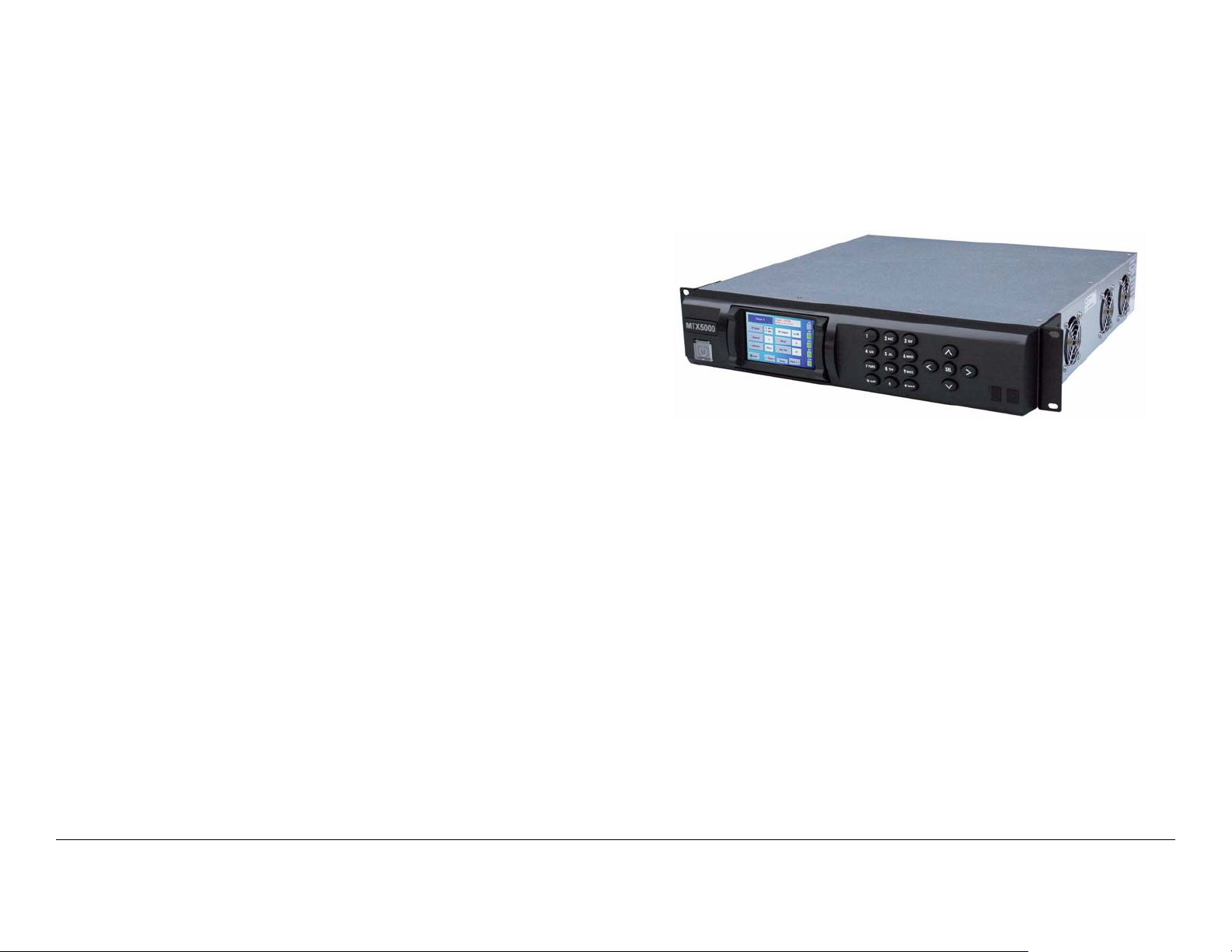
2.2.4 RF Control
The MTX5000 IDU (Figure 2-1) is designed to accept a variety of
external video and audio signals in different digital format
streams and analog sign als an d to pr o v id e a m od ulated 70 MHz
IF output.
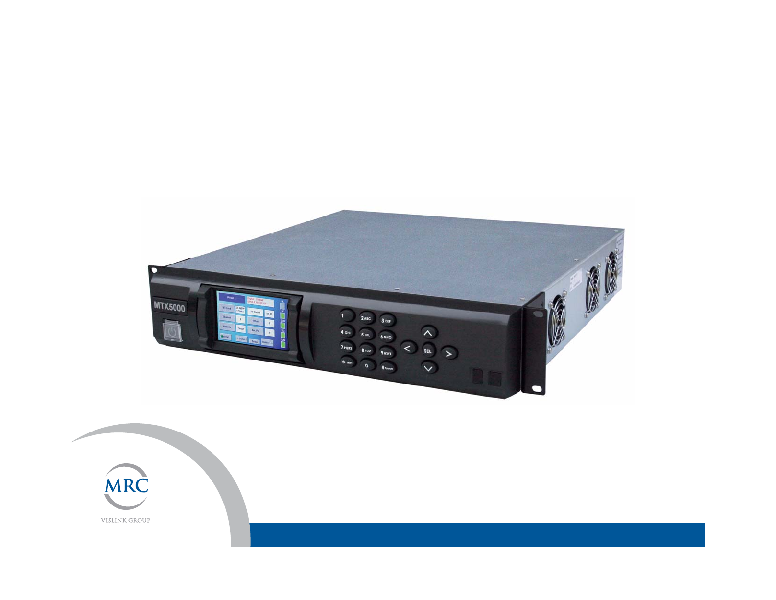
Figure 2-1: MTX5000 Indoor Unit
The MTX5000 IDU allows you to switch between analog a nd
digital modes where both applicat ions are used. The MTX5000
also provides separate video and audio or baseband composite
operations.
Key features of the MTX5000 IDU are as follows:
2.2.3 Analog Video Encoding a nd FM Modulation
When in the analog FM mode, the MTX5000 will accept a
standard composite video input. It will also accept analog audio
inputs. The FM analog signal is useful when working with older
legacy equipment or when an analog transmission is desired.
The MTX5000 IDU communicates with the ODU to set operating
frequencies and power levels. This interface is also used for
calibration of th e ODU power supply and to monitor error
conditions.
Product Description 2-2MTX5000 User and Technical Manual
• Switchable Analog or Digital modes
• SD/HD SDI interfaces with multiplexing
• Integrated SD/HD MPEG-2/H.264 encoding technologies
• FM transmitter modulation technology (analog)
• DVB-T COFDM modulation technology (digital)
• IF (70 MHz) signal input and monitoring
• Video monitoring output
• Video and audio inputs for NTSC or PAL video/audio
signal transmission
• Front panel keypad and touch screen display for
operation and control
• Multiple configuration options available
Figure 2-3: Typical MTX5000 Transmitter System
Antenna
• Built-in digital Color Bar Generator
• Optional analog Color Bar Generator is available.
The MRC ODU (See Figure 2-2) performs the signal upconversion from 70 MHz IF to RF (2 GHz or 7 GHz) a nd provides
signal amplification, as required. For dual band operation, two
separate ODUs are required, one for 2 GHz operation, and one
for 7 GHz operation.
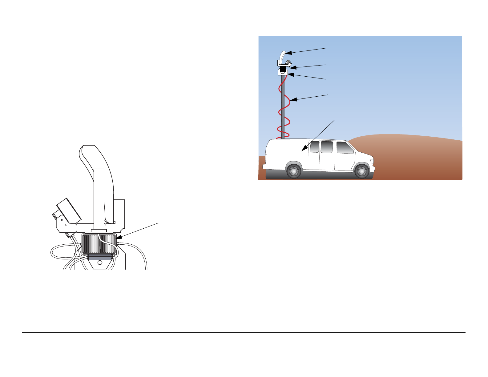
Figure 2-2: Outdoor Unit - Typical
Outdoor Unit Typical Installation
Pan & Tilt Assembly
Outdoor Unit (ODU)
Conduit (Nycoil)
Indoor Unit (IDU)
(Inside Ve hicle)
2.3 System Components
The MTX5000 system consists of the IDU and the ODU(s). A
typical system is shown in Figure 2-4 on page 2-4. The IDU
contains the baseband cir cui try, power supply, and control
modules. It accepts a wide variety of audio and video inputs,
both analog and digi tal, and generates a 70 MHz IF output. The
IDU also accepts IF inputs from external modulators.
A typical installation is shown in Figure 2-3. The MTX5000 IDU
is typically mounted in a standard 19 -inch (48.3 cm) rack for
mobile installations. The ODU is mounted on an antenna mast.
Product Description 2-3MTX5000 User and Technical Manual
The IDU can be controlled locally from the front panel controls or
it can be controlled remotely. The IDU can be controlled from a
PC at a remote location, such as a studio, via the PC web
browser. The optional Remote Access Subnotebook PC can
also be used to provide remote control of the IDU during mobile
operations.
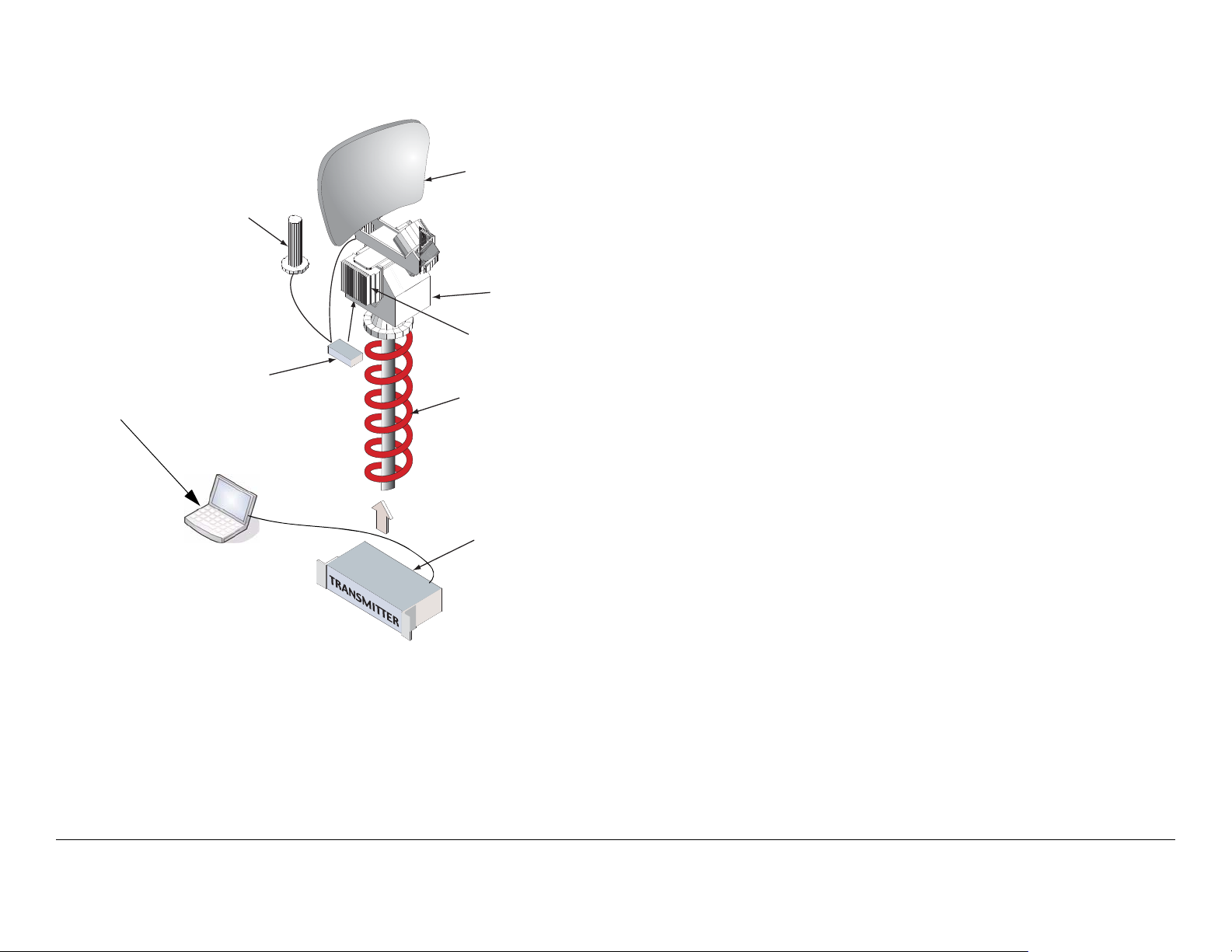
Figure 2-4: MTX5000 System Components - Typical
m
i
d
Directional Antenna
(MRC 2A20, 7A30,
Ellipse 2000, etc.)
Pan & Tilt Asse
Outdoor RF Unit
(Upconvertor,
Power Amp)
Conduit (Nycoil)
MTX5000 Indoor Un
(Baseband, Audio/Vi
Modules)
Laptop PC,
Remote Access
Subnotebook PC,
or PC
OmniPole
Antenna
RF Switch
the IF to the RF operating band required, and amplifies the RF
output, as required.
All installations will include an antenna, either directional,
omnidirectional, or both . An MRC RF switch ca n be mou nted on
the antenna mast to select the antenna required.
When using the mast-mounted antenna(s), a Nycoil co nduit
sheath covers the wiring harness between the IDU and the ODU.
The wiring harness carries the DC po w er, 70 MHz IF, and
antenna band and polarization switching control. Additional
wiring is contained in the Nycoil conduit sheath for controlling the
antenna pan and tilt mechanism a nd for implementing addition al
functions such as off-air monitors, mast lights, etc.
2.4 IDU Operating Controls
All controls are located on the front panel of the MTX5000 IDU.
There are no cont rols on the ODU.
All transmitter functions are controll ed using the color LCD
display panel touch screen and/or function keys, as shown in
Figure 2-5 on page 2-5.
The color LCD displa y panel w ith touch screen an d function ke ys
are used to select control and diagnostic menu screens for both
the IDU and the ODU. Option buttons displayed on the color
LCD display panel are used to control Preset selection, RF band
selection, channel selection, offset selection, antenna selection,
antenna polarization, transmitter operation (on or off), power
(low or high), and to monitor the status of the IDU and ODU.
For digita l oper ati on, the ID U is equip ped w ith an inter nal MPEG/
COFDM module.
The ODU contains the upconverters and the power amplifier.
The ODU accepts the 70 MHz IF output from the IDU, converts
Product Description 2-4MTX5000 User and Technical Manual
The option buttons displayed on the color LCD display panel
may be selected using either the color LCD display panel touch
screen or the function keys.
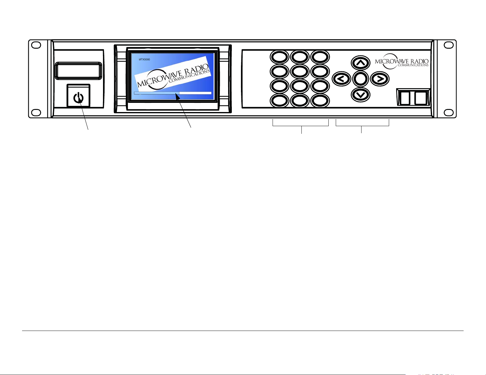
Figure 2-5: MTX5000 Front Panel View
MTX5000
Power Switch
Color LCD Display
Panel with Touch
Screen
2.5 External Connectors
The rear panels of the MTX5000 IDU configurations contain the
I/O connectors and an input fuse, as shown in Figure 2-6 on
page 2-6. Connectors contained on the ODU are shown in
Figure 2-7 on page 2-6.
The MTX5000 system is designed to make upgrading from an
older radio as easy as possible. The IDU and ODU can be
ordered with a variety of connectors to plug into an existing
wiring harness. Connectors available for the cable connection
between the IDU and ODU are as follows:
• Triax (both ends)
• Type “N” (both ends)
• TNC (both ends).
If your MTX5000 system contains the TNC connector option on
the IDU, a TNC connector must be atta ched to the ODU end of
the cable for weather and reliability purposes.
1
4
7
*
2
ABC
GHI
5
JKL
PQRS
8
TUV
Shift
0
Keypad (Not
3
DEF
6
MNO
9
WXYZ
#Space
SEL
Function Keys
Currently
Operational)
All ODU configurations contain a standard Type “N” connector
for connection to the antenna.
If your MTX5000 sy stem IDU is eq uipped with either Type “N” or
TNC connectors, the IDU will contain an 8-pin Weidmuller
connector to provide DC power and control to the ODU via the
ODU POWER connector.
If your system is equipped with Triax connectors, the 8-pin
Weidmuller connector will not be present on the rear panel of
the IDU. With the Triax connector option, both DC power and
control are provided to the ODU via the Triax cable connected
between the IDU and the ODU. If the Triax connector option is
contained on your MTX5000 system, a POWER connector will
not be present on the ODU.
For additional information, refer to the “ Insta l lation ” Chapter on
page 6-1.
Product Description 2-5MTX5000 User and Technical Manual Product Description 2-5MTX5000 User and Technical Manual
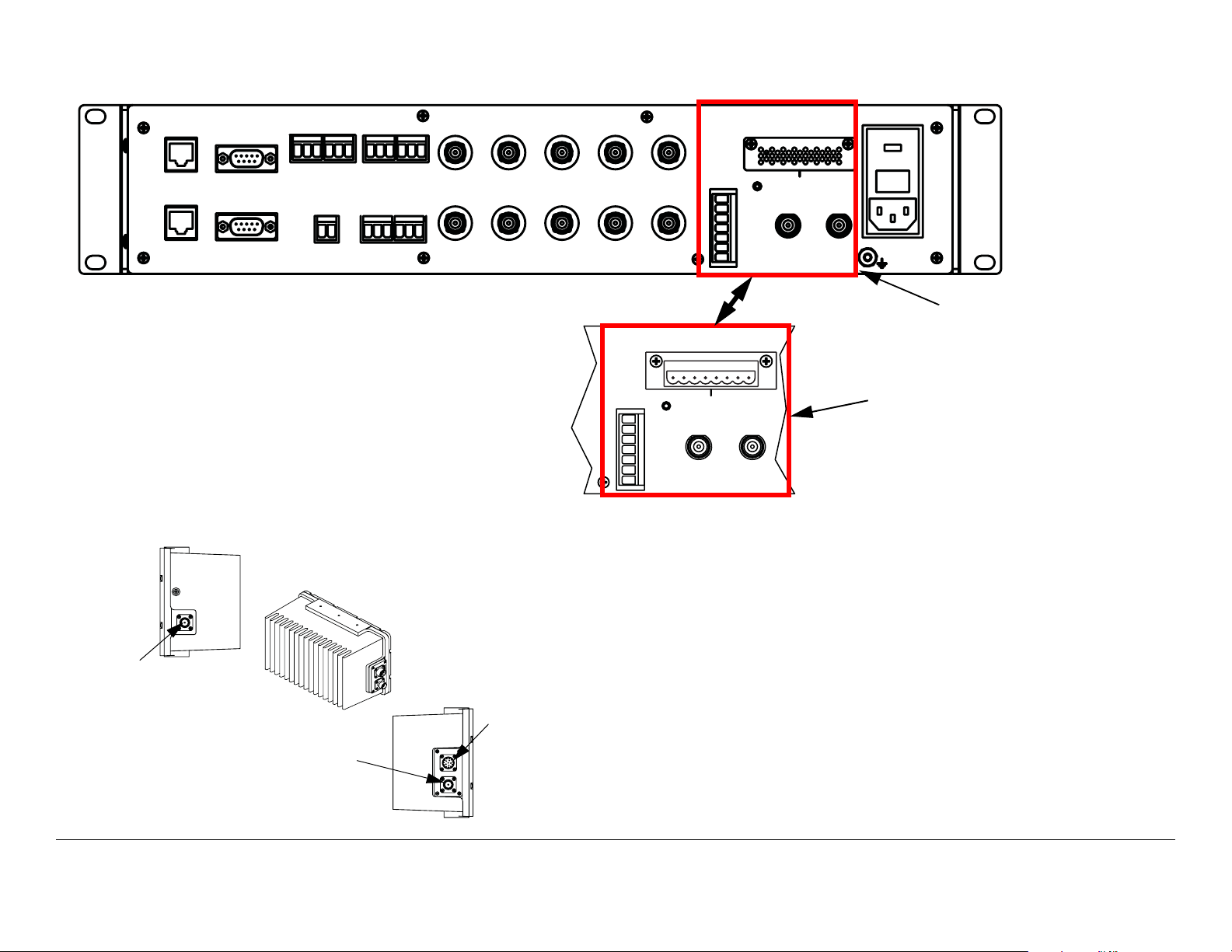
Figure 2-6: MTX5000 IDU Rear Panel Configurations
AUDIO
2
ETHERNET
RTN DATA
WAYSIDE
ATP C
+ G -
1
+ G -
SUM
ALARM
+ G -
1
+ G -
3
AES/EBU
Figure 2-7: MTX5000 ODU Connectors
RF OUT
RF OUT
Connector
RF IN
Connector
+ G -
2
+ G -
4
BB IN
VIDEO IN
IF MON
AC-3
SMPTE 302
ASI 1 HD-SDI ASI 2
IF IN
VID MON
SDI/ASI
ANT
CONTROL
H
V
LCP
ANT2
BAND2
GND
+
RFU POWER OUT
- - + +
1
RFU 1
- - + +
2
RFU 2
POWER IN
MTX5000 IDU
Configuration with Triax
Connectors
ANT
CONTROL
H
V
LCP
ANT2
BAND2
GND
+
RFU POWER OUT
- - + +
1
RFU 1
- - + +
2
RFU 2
MTX5000 IDU
Configuration with Type
“N” or TNC Connectors
The IDU connects to the ODU through the wiring harness
between the units. The wiring harness contains DC power, 70
MHz IF, and control for all components mounted on the top of
the antenna mast. Functi ons and control contai ned in the wir ing
POWER
Connector
(With TNC
and Type
“N” RF IN
Connector
IDU
Options
RF IN
Only)
harness typically include the following:
• 70 MHz IF, control, and alarms between the IDU and the
ODU
• DC power to the ODU
• Power and control for an RF switch to select antennas
• Power and control for antenna switchin g functions (ba nd,
polarization, and power)
Product Description 2-6MTX5000 User and Technical Manual Product Description 2-6MTX5000 User and Technical Manual
• Power for mast top lights
• Control and power for the Pan and Tilt assembly
• RF and control for an off-air antenna
• Mast top safety sensors for proximity, high voltage, etc.
AC power is applied to the MTX5000 IDU, which in turn, provides
DC power to the ODU via the wiring harness b etwe en them.
Refer to the “ Installation” Chapter on page 6-1 for additional
information.
Since each installation may be different, the harness must be
specified for each installation. The harness can be supplied by
MRC, or it is often supplied by the van integrator.
2.6 Configuration Options
MRC is constantly working to expand and upgrade the
capabilities of the MTX5000. Consult your Sales Representative
or contact the factory for the latest information.
2.6.1 IDU Configurations
Your MTX5000 IDU consists of an MPEG encoder, a COFDM
modulator, and an analog FMT module.
2.6.2 AC Power
The MTX5000 IDU operates on the following AC power:
• 120/240 VAC, 50/60 Hz
Fuse ratings for the AC power sources are listed in Table 2-1.
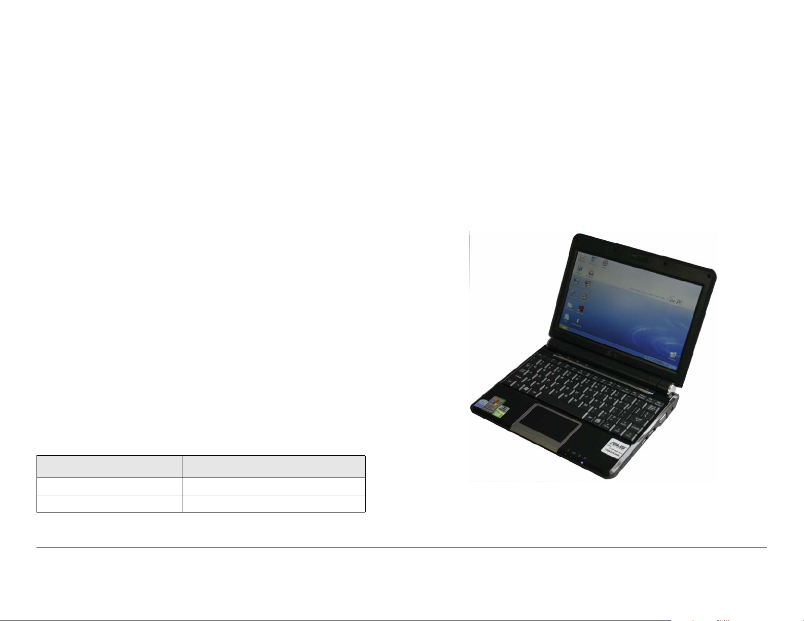
2.6.3 Remote Control Options
For portable mobile operations, the MTX5000 system may be
controlled using either a Windows-based laptop PC or by the
optional Window s-based Remote A ccess Subnotebo ok PC. See
Figure 2-8.
Figure 2-8: Remote Access Subnotebook PC
Table 2-1: AC Fuse Ratings
Operating Volt age Fuse Rating
120 VAC, 50/60 Hz 3.0A SB 250V 3AG or 5 x 20 mm
240 VAC, 50/60 Hz 1.5A SB 250V 3AG or 5 x 20 mm
Using either PC eliminates the need for a separate panelmounted remote control panel to control the MTX5000 system.
Product Description 2-7MTX5000 User and Technical Manual

An RJ-45 crossover cable is required for connection to
either PC for mobile remote control operations.
The MTX5000 system may also be controlled from a Windowsbased PC at a remote location. When controlling the MTX5000
system from a remote location, the remote PC is connected to
the MTX5000 system via the Ethernet.
To connect Windows-based PCs to the MTX5000 system, see
”Select Local/Remote Operation Mode” on page 3-20. To
connect the o ptional Windows-based Remot e Access
Subnotebook PC to the MTX5000 system, refer to the Remote
Access Subnotebook PC Operator’s Guide, part number
400573-1, provided with the optional Remote Access
Subnoteboo k PC.
• MRC Ellipse 2000
• MRC OmniPole Omnidirectional.
Switching functions for band and antenna polarizat i on are
controlled from the front panel of the IDU.
If your installation involves more than one antenna, this can be
easily accommodated by using an MRC RF Switch. The RF
Switch is also controlled from the front panel of the IDU.
2.6.5 Band and Frequency Options
The MTX5000 system is designed to cover one or more bands.
It can be ordered as a single-band unit or as a dual-band
configuration to cover the following bands.
Information and procedures required to control the MTX5000
system for either portable mobile applications or for remote
location operations are provided in “Using the MTX5000 in
Remote Mode” o n p ag e 3-60 and “Remote Locati on Op erat ions”
on page 3-67. Procedures required to control the MTX5000
system using either a Windows-based laptop PC, the optional
Windows-based Remote Access Subnotebook PC, or a
Windows-based PC at a remote location are identical.
2.6.4 Antenna Options
The MTX5000 system is fully compatible with a variety of
antennas, including:
• MRC ProStar, models
- 2A20 and 2A20SS (2 GHz)
- 7A30 and 7A30SS (7 GHz)
- 2A20/7A30 (dual band 2 & 7 GHz)
- 2A20/7A30SS (dual ban d 2 & 7 GHz, solid st ate
switching)
• 2 GHz (17 MHz)
• 2 GHz (12 MHz)
• 7 GHz Lower.
Band and frequency information is stored in the RFU, which
means switching bands after installation is very simple: just plug
in the RFU for the new band and the IDU will automa tically
configure itself for the new band.
Within these bands, channels can be pre-programmed at the
factory to match either the U.S. bro adcast chan nel pl an or a pla n
specified by the customer.
2.7 System Configurations
The MTX5000 system provides several antenna configuration
options to transmit using either an omni antenna or a directional
antenna, in either single-band or dual-band operation.
Product Description 2-8MTX5000 User and Technical Manual
 Loading...