

Operator’s Guide
Manual Part No. 400537-1
Rev. B May 2008
High Performance Analog + Digital
Integrated Receiver Decoder (IRD)
MRX4000 PLUS


Notices iMRX4000 PLUS Operator’s Guide
Notices
About This Manual
Part number 400537-1
Revision B May 2008
The information in the manual applies to the Microwave Radio
Communications (MRC) MRX4000 PLUS High Performance
Analog + Digital Integrated Receiver Decoder (IRD).
Copyright
The information in this manual may only be reproduced by the
purchaser strictly for its own internal use to the extent required
for its use of the product, and shall only be made available to
purchaser’s employees who need access to this material. No
part of this material, nor any copies hereof, shall in any manner
be disclosed, disseminated, or made available by purchaser or
its employees to any other person, firm, or entity without the
express prior written consent of Microwave Radio
Communications nor shall the same in any manner be modified
or published for resale without the express prior written
authorization of Microwave Radio Communications.
© 2008 Microwave Radio Communications
Microwave Radio Communications
101 Billerica Avenue - Bldg. 6
North Billerica, MA 01862-1256 USA
TEL: 800.490-5700
978.671.5700
FAX : 978.671.5800
Printed in U.S.A.
Adobe®, the Adobe logo, Acrobat®, and Reader® are registered
trademarks of Adobe Systems, Inc. in the United States and/or
other countries. Microsoft® and Windows® are registered
trademarks of Microsoft Corporation in the United States and/or
other countries.
Proprietary Material
The information and design contained within this manual was
originated by and is the property of Microwave Radio
Communications. Microwave Radio Communications reserves
all patent proprietary design, manufacturing, reproduction use,
and sales rights thereto, and to any articles disclosed therein,
except to the extent rights are expressly granted to others. The
foregoing does not apply to vendor proprietary parts.
Microwave Radio Communications has made every effort to
ensure the accuracy of the material contained in this manual at
the time of printing. As specifications, equipment, and this
manual are subject to change without notice, Microwave Radio
Communications assumes no responsibility or liability
whatsoever for any errors or inaccuracies that may appear in this
manual or for any decisions based on its use. This manual is
supplied for information purposes only and should not be
construed as a commitment by Microwave Radio
Communications.
Quality Certification
Microwave Radio Communications is certified to ISO 9001:2000.
Authorized EU representative: Vislink PLC.
Notices iiMRX4000 PLUS Operator’s Guide
Conventions
Pay special attention to information marked in one of the
following ways:
WARNING
Follow WARNINGS closely to prevent
personal injury or death.
CAUTION
Follow CAUTIONS to prevent damage to
the equipment.
Note
Notes provide additional information to assist you
in using and maintaining the equipment.
Waste Electrical and Electronic
Equipment
The crossed out dustbin symbol on the product
indicates that the product must not be disposed of
with other waste at the end of its lifecycle. Instead, it
is the user’s responsibility to dispose of the waste
equipment by handing it over to a designated collection point for
the recycling of Waste Electrical and Electronic Equipment
(WEEE). For more information about where you can drop off
your waste equipment for recycling, please contact your local
government office.
Except for this notification and the proper marking of products
with the appropriate symbol, Microwave Radio Communications
disclaims responsibility for the disposal of its products per the
WEEE directive.
Symbols Used
The following symbols are used on the equipment:
Symbol Meaning
WARNING: General Warning. Risk of Danger.
WARNING: Risk of Electric Shock.
WARNING: Electrostatic Discharge. Possible
Damage to Equipment.
Fuse - Identifies fuses or their location.
Frame or Chassis Ground - Identifies the frame or
chassis terminal.
Earth Ground - Identifies the earth ground terminal.
Protective Earth Ground - Identifies any terminal
which is intended for connection to an external
conductor for protection against electric shock in
case of a fault, or the terminal on a protective earth
electrode.
OR

Notices iiiMRX4000 PLUS Operator’s Guide
On-Line Viewing
Text displayed as blue contains a hypertext link. Click on the
hypertext to jump to that destination. Click on the
blue destination to return.
Warranty Information
Products Manufactured by MRC
a. Products manufactured by MRC are warranted against
defects in material and workmanship for a period of two (2) years
from date of delivery as evidenced by MRC's packing slip or
other transportation receipt (unless otherwise noted).
b. MRC's sole responsibility under this warranty will be to either
repair or replace, at its option, any component which fails during
the applicable warranty period because of a defect in material or
workmanship, provided Buyer has promptly reported same to
MRC in writing. All replaced products and parts will become
MRC's property.
c. MRC will honor the warranty at the repair facility designated
by MRC. It is Buyer's responsibility to return, at its expense, the
allegedly defective product to MRC. Buyer must obtain a Return
Viewing this manual on-line
requires Adobe Acrobat or
Adobe Reader, version 5.0 and
later.
Click on this icon to download
your FREE copy of Adobe
Reader.
Material Authorization (RMA) number and shipping instructions
from MRC prior to returning any product under warranty.
Transportation charges for the return of the product to Buyer will
be paid by MRC within the United States. For all other locations,
the warranty excludes all costs of shipping, customs clearance,
and other related charges. If MRC determines that the product is
not defective within the terms of this warranty, Buyer will pay
MRC all costs of handling, transportation, and repairs at the then
prevailing repair rates.
d. All the above warranties are contingent upon proper use of
the product. These warranties will not apply (1) if adjustment,
repair, or product or parts replacement is required because of
accident, unusual physical, electrical or electromagnetic stress,
neglect, misuse, failure of electric power, environmental controls,
transportation, failure to maintain properly, or otherwise in
accordance with MRC specifications, or abuses other than
ordinary use; (2) if the product has been modified by Buyer or
has been repaired or altered outside MRC's repair facility, unless
MRC specifically authorizes such repairs or alterations in each
instance; or (3) where MRC serial numbers, warranty data, or
quality assurance decals have been removed or altered.
e. Equipment shipped FOB from Microwave Radio
Communications shall become the property of the buyer upon
delivery and receipt from the carrier. Any damage in shipment
should be handled by the buyer directly with the carrier.
Immediately request the carrier’s inspection upon evidence of
damage during shipment. Do not return any Microwave Radio
Communications product to the factory until a Return Material
Authorization (RMA) number and shipping instructions have
been provided.
f. No person, including any dealer, agent, or representative of
MRC, is authorized to assume for MRC any other liability on its
behalf except as set forth herein. If any payment is due MRC for

Notices ivMRX4000 PLUS Operator’s Guide
services performed hereunder, it will be subject to the same
payment terms as the original purchase.
Products Manufactured By Others
For products not manufactured by MRC, the original
manufacturer's or licensor's warranty will be assigned to Buyer to
the extent permitted by the manufacturer or licensor and is in lieu
of any other warranty, expressed or implied. For warranty
information on a specific product, a written request should be
made to MRC.
All Products
THE FOREGOING WARRANTIES AND REMEDIES ARE
EXCLUSIVE AND ARE IN LIEU OF ALL OTHER EXPRESS OR
IMPLIED WARRANTIES, OBLIGATIONS, AND LIABILITIES ON
THE PART OF MRC. EXCEPT FOR THE EXPRESS
WARRANTIES STATED HEREIN, MRC DISCLAIMS ALL
WARRANTIES ON PRODUCTS FURNISHED HEREUNDER,
INCLUDING, WITHOUT LIMITATION, ALL IMPLIED
WARRANTIES OF MERCHANTABILITY AND FITNESS FOR A
PARTICULAR PURPOSE. MRC WILL HAVE NO
RESPONSIBILITY FOR ANY PARTICULAR APPLICATION
MADE OF ANY EQUIPMENT.
Any description of equipment, whether in writing or made orally
by MRC or its agents, specification sheets, models, bulletins,
drawings, or similar materials used in connection with Buyer's
order are for the sole purpose of identifying the equipment and
will not be construed as an express warranty. Any suggestions
by MRC or its agents regarding use, application, or suitability of
the equipment will not be construed as an express warranty. No
warranties may be implied from any course of dealing or usage
of trade. Buyer agrees that the exclusion of all warranties, other
than those expressly provided herein, is reasonable.

Contents 1MRX4000 PLUS Operator’s Guide
Contents
Notices - - - - - - - - - - - - - - - - - - - - - - - - - - - - - - - - i
About This Manual - - - - - - - - - - - - - - - - - - - - - - - - - - - - i
Copyright - - - - - - - - - - - - - - - - - - - - - - - - - - - - - - - - - - - i
Proprietary Material - - - - - - - - - - - - - - - - - - - - - - - - - - - - i
Quality Certification - - - - - - - - - - - - - - - - - - - - - - - - - - - - i
Conventions - - - - - - - - - - - - - - - - - - - - - - - - - - - - - - - - - ii
Waste Electrical and Electronic Equipment - - - - - - - - - - - ii
Symbols Used- - - - - - - - - - - - - - - - - - - - - - - - - - - - - - - - ii
On-Line Viewing - - - - - - - - - - - - - - - - - - - - - - - - - - - - - - iii
Warranty Information - - - - - - - - - - - - - - - - - - - - - - - - - - - iii
Products Manufactured by MRC - - - - - - - - - - - - - - - - iii
Products Manufactured By Others - - - - - - - - - - - - - - iv
All Products - - - - - - - - - - - - - - - - - - - - - - - - - - - - - - iv
Contents - - - - - - - - - - - - - - - - - - - - - - - - - - - - - - 1
Introduction - - - - - - - - - - - - - - - - - - - - - - - - - - - 1-1
Chapter Overview - - - - - - - - - - - - - - - - - - - - - - - - - - - 1-1
How to Use This Manual - - - - - - - - - - - - - - - - - - - - - - 1-1
What This Manual Covers - - - - - - - - - - - - - - - - - - - - - 1-1
How It’s Organized - - - - - - - - - - - - - - - - - - - - - - - - - - 1-1
For Whom It’s Written - - - - - - - - - - - - - - - - - - - - - - - - 1-2
Related Documents - - - - - - - - - - - - - - - - - - - - - - - - - - 1-2
Ordering Documentation - - - - - - - - - - - - - - - - - - - - - - 1-2
Calling for Service - - - - - - - - - - - - - - - - - - - - - - - - - - - 1-3
Supported Repairs - - - - - - - - - - - - - - - - - - - - - - - - - - 1-3
Tell Us What You Think! - - - - - - - - - - - - - - - - - - - - - - 1-4
Product Description- - - - - - - - - - - - - - - - - - - - - 2-1
Chapter Overview - - - - - - - - - - - - - - - - - - - - - - - - - - - 2-1
System Descriptions - - - - - - - - - - - - - - - - - - - - - - - - - 2-1
MRX4000 PLUS Description - - - - - - - - - - - - - - - - - 2-1
MRX4000 PLUS Configuration Options - - - - - - - - - 2-2
Configuration Descriptions - - - - - - - - - - - - - - - - - - 2-2
Power Options - - - - - - - - - - - - - - - - - - - - - - - - - - - 2-5
Mounting and Deployment Options - - - - - - - - - - - - - 2-5
System Operation - - - - - - - - - - - - - - - - - - - - - - - - - 2-5
MRX4000 PLUS Configurations- - - - - - - - - - - - - - - - - - 2-6
MPEG/COFDM Digital Configuration - - - - - - - - - - - - 2-6
FMR NTSC/PAL Analog Configuration - - - - - - - - - - 2-6
MPEG/COFDM/FMR NTSC/PAL Digital + Analog
Configuration - - - - - - - - - - - - - - - - - - - - - - - - - - - - 2-6
For More Information - - - - - - - - - - - - - - - - - - - - - - - - - 2-6
Routine Operation - - - - - - - - - - - - - - - - - - - - - - 3-1
Chapter Overview - - - - - - - - - - - - - - - - - - - - - - - - - - - 3-1
Overview of Controls, Indicators and Connectors - - - - - 3-1
Controls and Indicators - - - - - - - - - - - - - - - - - - - - - 3-1
MRX4000 PLUS Digital and Digital + Analog
Configuration Connectors- - - - - - - - - - - - - - - - - - - - 3-3
MRX4000 PLUS Analog Configuration Connectors- - 3-5
Preparing for Operation - - - - - - - - - - - - - - - - - - - - - - - 3-7
Fixed or Mobile Installation- - - - - - - - - - - - - - - - - - - 3-7
Powering the MRX4000 PLUS - - - - - - - - - - - - - - - - 3-7
Using the MRX4000 PLUS Screens - - - - - - - - - - - - - - - 3-8
Overview - - - - - - - - - - - - - - - - - - - - - - - - - - - - - - - 3-8
Menu Configurations - - - - - - - - - - - - - - - - - - - - - - 3-11
Main Screen - - - - - - - - - - - - - - - - - - - - - - - - - - - - 3-11
Cursors - - - - - - - - - - - - - - - - - - - - - - - - - - - - - - - 3-11
Accessing Menus - - - - - - - - - - - - - - - - - - - - - - - - 3-13
Monitoring Operations - - - - - - - - - - - - - - - - - - - - - - - 3-13
Monitor/Change MPEG Settings - - - - - - - - - - - - - - - - 3-13
Monitor/Change Color Bars - - - - - - - - - - - - - - - - - 3-16
Monitor/Change Audio Output Mode Setting - - - - - 3-17
Monitor/Change NTSC Pedestal - - - - - - - - - - - - - - 3-18
Monitor/Change BISS Settings - - - - - - - - - - - - - - - 3-20
Monitor Audio A - - - - - - - - - - - - - - - - - - - - - - - - - 3-21
Monitor Audio B - - - - - - - - - - - - - - - - - - - - - - - - - 3-23
Monitor Video Status - - - - - - - - - - - - - - - - - - - - - - 3-24

Contents Contents-2MRX4000 PLUS Operator’s Guide
Monitor Chroma Status - - - - - - - - - - - - - - - - - - - - 3-25
Monitor Service Name - - - - - - - - - - - - - - - - - - - - 3-26
Monitor/Change COFDM Settings - - - - - - - - - - - - - - 3-28
Monitor/Change Bandwidth - - - - - - - - - - - - - - - - - 3-30
Monitor Modulator Type - - - - - - - - - - - - - - - - - - 3-31
Monitor Forward Error Correction - - - - - - - - - - - - - 3-32
Monitor Guard Interval - - - - - - - - - - - - - - - - - - - - 3-34
Monitor COFDM Metrics - - - - - - - - - - - - - - - - - - - 3-35
Monitor/Change FMR Settings - - - - - - - - - - - - - - - - - 3-37
Monitor/Change Video Filter - - - - - - - - - - - - - - - - 3-39
Monitor/Change Video Deviation - - - - - - - - - - - - - 3-40
Monitor/Change Channel 1, 2, 3, or 4 Sub-Carrier
Frequencies - - - - - - - - - - - - - - - - - - - - - - - - - - - - 3-42
Monitor/Enable/Disable Channel 1, 2, 3, or 4 - - - - 3-43
Monitor/Enable/Disable Channel 1, 2, 3, or 4
Filtering - - - - - - - - - - - - - - - - - - - - - - - - - - - - - - - 3-45
Monitor/Enable/Disable Channel 1, 2, 3, or 4 De-
Emphasis - - - - - - - - - - - - - - - - - - - - - - - - - - - - - 3-46
Monitor/Change MRX4000 PLUS RF/IF Section
Settings - - - - - - - - - - - - - - - - - - - - - - - - - - - - - - - - - 3-48
Monitor Channel Frequency - - - - - - - - - - - - - - - - 3-50
Monitor Received Carrier Level - - - - - - - - - - - - - - 3-51
Monitor Link Quality - - - - - - - - - - - - - - - - - - - - - - 3-52
Select Frequency Band - - - - - - - - - - - - - - - - - - - 3-53
Monitor Channel Bandwidth - - - - - - - - - - - - - - - - 3-55
Select Channel and Offset - - - - - - - - - - - - - - - - - 3-56
Change Filter Setting - - - - - - - - - - - - - - - - - - - - - 3-58
Change Squelch Level - - - - - - - - - - - - - - - - - - - - 3-59
Change Analog/Digital Operation Mode - - - - - - - - 3-61
Change IF/RF Operation Mode - - - - - - - - - - - - - 3-63
Monitor/Change System Menu Options - - - - - - - - - - - 3-65
Monitor/Change Active Preset - - - - - - - - - - - - - - - 3-67
Monitor Active Errors - - - - - - - - - - - - - - - - - - - - - 3-67
Review Error Log - - - - - - - - - - - - - - - - - - - - - - - - 3-68
Review System Information - - - - - - - - - - - - - - - - - 3-69
Perform System Reset- - - - - - - - - - - - - - - - - - - - - 3-70
Front Panel vs. Configurator Software - - - - - - - - - - - - 3-71
Troubleshooting - - - - - - - - - - - - - - - - - - - - - - - 4-1
Chapter Overview - - - - - - - - - - - - - - - - - - - - - - - - - - - 4-1
Status LEDs - - - - - - - - - - - - - - - - - - - - - - - - - - - - - - - 4-1
Error Codes - - - - - - - - - - - - - - - - - - - - - - - - - - - - - - - - 4-2
Glossary - - - - - - - - - - - - - - - - - - - - - - - - - - - - - A-1
Channels & Frequencies - - - - - - - - - - - - - - - - - B-1
Appendix Overview - - - - - - - - - - - - - - - - - - - - - - - - - - B-1
Initial Factory Presets - - - - - - - - - - - - - - - - - - - - - - - - - B-1
6.4 to 7.1 GHz Channel Plan - - - - - - - - - - - - - - - - - B-1
12.7 to 13.25 GHz Channel Plan- - - - - - - - - - - - - - - B-2
US 2 GHz Reallocation - 12 MHz Channel Plan - - - - - - B-2
MRX4000 PLUS Specifications - - - - - - - - - - - - C-1
Index - - - - - - - - - - - - - - - - - - - - - - - - - - - - - - - - - - 1

1
Introduction 1-1MRX4000 PLUS Operator’s Guide
Introduction
1.1 Chapter Overview
This chapter will introduce you to the Operator’s Guide: what it
covers, how it’s organized, and for whom it’s written.
1.2 How to Use This Manual
A CD ROM, delivered with each MRX4000 PLUS High
Performance Analog + Digital Integrated Receiver Decoder
(IRD) (MRX4000 PLUS), contains PDF files for the Operator’s
Guide, Technical Reference Manual, and the Quick Reference
Card.
The Operator’s Guide, the Technical Reference Manual, and the
Quick Reference Cards are also available for download through
the MRC E-Synergy Customer Portal. For more information or to
obtain a User Name and Password, please go to:
http://www.mrcglobalsolutions.com/support/e_synergy_portal
Hardcopies of the Operator’s Guide and Technical Reference
Manual are provided only if they were requested when your
equipment was ordered.
Viewing of this manual on-line requires Adobe Acrobat software
or Adobe Reader software, Version 5.0 and later. Click on the
following icon to download your FREE copy of the latest Adobe
Reader software.
When viewing this manual on-line, text displayed as blue
contains a hypertext link. Click on the blue hypertext link to
jump to that destination. If the destination link is also blue, click
on the blue destination link to return.
1.3 What This Manual Covers
This manual describes how to operate the MRX4000 PLUS.
For information on Installation, Repair, Replacement Parts, and
Theory of Operation, refer to the MRX4000 PLUS Technical
Reference Manual
This manual also covers various configurations of the MRX4000
PLUS. Your MRX4000 PLUS will consist of one of the following
configurations:
• MPEG/COFDM/FMR NTSC - Analog + Digital with RF/IF
Section
• MPEG/COFDM/FMR PAL - Analog + Digital with RF/IF
Section
• FMR NTSC - Analog Only with RF/IF Section
• FMR PAL - Analog Only with RF/IF Section
• MPEG/COFDM - Digital Only with RF/IF Section
Your MRX4000 PLUS will be rack-mounted in a standard 19-inch
(43.9 cm) rack for fixed site operations.
1.4 How It’s Organized
The manuals for the MRX4000 PLUS are organized as follows:

Introduction 1-2MRX4000 PLUS Operator’s Guide
Chapter
Operator’s
Guide
Technical
Reference
Manual
Introduction ✔ ✔
Product Description ✔ ✔
Routine Operation ✔ ✔
Troubleshooting ✔ ✔
Advanced Operation ✔
Installation ✔
Repair ✔
Replacement Parts ✔
Theory of Operation ✔
Glossary ✔ ✔
Channels and
Frequencies
✔ ✔
Configuration Utility ✔
MRX4000 PLUS
Specifications
✔ ✔
Note
The Technical Reference Manual contains
everything in the Operator’s Guide, plus additional
technical content.
1.5 For Whom It’s Written
This manual is intended for use by qualified installers and
service personnel. Users of this manual should already be
familiar with basic concepts of radio, video, and audio.
1.6 Related Documents
• MRX4000 PLUS Technical Reference Manual (part no.
400538-1)
• MRX4000 PLUS Quick Reference Card (part no. 400539-
1)
1.7 Ordering Documentation
Any of the above manuals may be ordered by contacting MRC
Customer Service:
Business Hours: Monday - Thursday
8:00 AM - 7:00 PM Eastern Time (US)
(0800 - 1900 hrs US ET)
Friday
8:00 AM - 5:00 PM Eastern Time (US)
(0800 - 1700 hrs US ET)
Telephone: 800-490-5700 (Press 3)
978-671-5700 (Press 3)

Introduction 1-3MRX4000 PLUS Operator’s Guide
Fax: 978-671-5948
E-mail: customerservice@mrcbroadcast.com
When contacting Customer Service, please have the following
information available:
• Model number and serial number of the unit. This is
located on a label on the left-hand side of each unit.
• Approximate purchase date.
• Firmware versions (depending upon the options
contained in your MRX4000 PLUS), which appear on the
MRX4000 PLUS alphanumeric display System Menus >
System Info > MRX DCC V:, Front Panel V:, MPEG V:,
MPEG FPGA V:, COFDM V:, and FMR V: menus.
or
• Firmware versions displayed on the Main page of the
MRX4000 PLUS Configuration Utility (Configurator)
software, when the Configurator is connected to the
MRX4000 PLUS.
1.8 Calling for Service
MRC Technical Support is available 24 hours a day, 7 days a
week. During regular business hours you can reach our expert
staff directly.
Business Hours: Monday - Friday
8:00 AM - 7:00PM Eastern Time (US)
(0800 - 1900 hrs US ET)
Telephone: 800-490-5700 (Press 4)
978-671-5700 (Press 4)
Fax: 978-671-5948
E-mail: technicalsupport@mrcbroadcast.com
After regular business hours and on weekends and holidays, you
can also reach our expert staff as follows:
Telephone: 978-671-5929
Your call will be automatically forwarded to the on-call Technical
Support Specialist.
When contacting Technical Support, please have the following
information available:
• Model number and serial number of the unit. This is
located on a label on the left-hand side of each unit.
• Approximate purchase date.
• Firmware versions (depending upon the options
contained in your MRX4000 PLUS), which appear on the
MRX alphanumeric display System Menus > System
Info > MRX DCC V:, Front Panel V:, MPEG V:, MPEG
FPGA V:, COFDM V:, and FMR V: menus.
or
• Firmware versions displayed on the Main page of the
MRX4000 PLUS Configuration Utility (Configurator)
software , when the Configurator is connected to the
MRX4000 PLUS.
1.9 Supported Repairs
The MRX4000 PLUS is designed to be compact, rugged, and
reliable.
The MRX4000 PLUS requires specialized test equipment and
software to calibrate amplitude and frequency characteristics
after repair.

Introduction 1-4MRX4000 PLUS Operator’s Guide
There are NO supported field repairs for the MRX4000 PLUS.
Return the entire unit for factory repair.
If you attempt field repair, you risk damaging your
equipment. If your equipment is under warranty, you may also
affect your warranty coverage.
1.10 Tell Us What You Think!
We’d appreciate any comments or suggestions you have about
this manual. The more feedback we get, the better the manuals
get!
If you’re viewing this manual electronically, it’s easy - just click on
the link below to send us an E-mail.
Or, you can E-mail our Technical Support team at:
technicalsupport@mrcbroadcast.com
Be sure to tell us what product you’re writing about, and which
manual - the Operator’s Guide, the Quick Reference Card, or the
Technical Reference Manual.
Feedback
2
Product Description 2-1MRX4000 PLUS Operator’s Guide/
Technical Reference Manual
Product Description
2.1 Chapter Overview
This chapter provides an overall description of the MRX4000
PLUS High Performance Analog + Digital Integrated Receiver
Decoder (IRD) (MRX4000 PLUS), components, and capabilities.
Here are the topics covered:
2.2 System Descriptions
2.2.1 MRX4000 PLUS Description
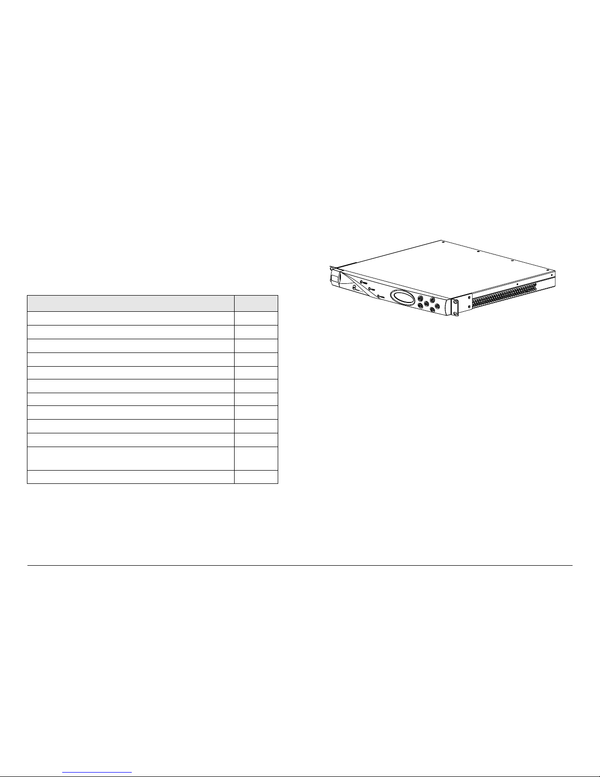
The MRX4000 PLUS (Figure 2-1) is a highly reliable, flexible,
and compact video microwave Electronic News Gathering (ENG)
Topic Page
System Descriptions
2-1
MRX4000 PLUS Description
2-1
MRX4000 PLUS Configuration Options
2-2
Configuration Descriptions
2-2
Power Options 2-5
Mounting and Deployment Options
2-5
System Operation 2-5
MRX4000 PLUS Configurations
2-6
MPEG/COFDM Digital Configuration
2-6
FMR NTSC/PAL Analog Configuration
2-6
MPEG/COFDM/FMR NTSC/PAL Digital +
Analog Configuration
2-6
For More Information
2-6
analog and digital central receiver systems with demodulation
and decode functions for fixed installations.
Figure 2-1: MRX4000 PLUS
The MRX4000 PLUS is a fully functional, standalone, state of the
art ENG central receiver for analog and digital formats and
includes the ability to support encapsulated Internet Protocol (IP)
packetized service from an ENG or Outside Broadcast (OB) or
portable transmitter.
The MRX4000 PLUS is rack-mounted in a standard 19-inch
(48.3 cm) rack for fixed site operations.
The MRX4000 PLUS is used in both analog and digital ENG
central receive site operations. The unit allows operators to
switch between analog and digital operation modes where both
applications are used. The MRX4000 PLUS also provides
separate video and audio or broadband composite operation.
According to different applications, the MRX4000 PLUS can be
factory-configured as a baseband signal Frequency Modulation
Receiver (FMR) for analog radio applications, can be configured
as a baseband COFDM Demodulator and MPEG Decoder for
digital radio applications, or can be configured to include FMR
and COFDM/MPEG for both analog and digital radio
applications.

Product Description 2-2MRX4000 PLUS Operator’s Guide/
Technical Reference Manual
Key features of the MRX4000 PLUS are as follows:
• Analog, digital, or analog + digital selectable
• RF/IF receiver with separate control unit techniques
• FMR receiver demodulation technology (analog) with
squelch capability
• COFDM demodulation and MPEG decoding technology
(digital)
• Digital demodulation for QPSK, 16QAM, and 64QAM
• IF (70 MHz) signal input and monitoring for demodulation
• Four selectable IF bandpass filters for both digital and
analog operations
• 900 MHz monitoring from the Low Noise Converter (LNC)
for system spectrum monitoring and display
• RF input for microwave radio applications (frequency from
1.99 to 2.5 GHz)
• ASI signal input and output connection interfaces
• SDI signal output connection interfaces
• Video and audio outputs for NTSC or PAL video/audio
signal transmission
• Front panel keypad and display operation and control
• Serial and parallel communication interface for remote
control and management
• Serial communication interface for remote control and
management
• Ethernet I/O interface for system control (Future Option Not currently active)
• System configuration control and management via the
MRX4000 PLUS Configuration Utility software
• Multiple configurations available.
2.2.2 MRX4000 PLUS Configuration Options
The MRX4000 PLUS is currently available in the following
configurations:
• MPEG/COFDM/FMR NTSC - Analog + Digital with RF/IF
Section
• MPEG/COFDM/FMR PAL - Analog + Digital with RF/IF
Section
• FMR NTSC - Analog Only with RF/IF Section
• FMR PAL - Analog Only with RF/IF Section
• MPEG/COFDM - Digital Only with RF/IF Section.
If your MRX4000 PLUS contains the analog FMR module, the
module will be be factory-configured for either NTSC or PAL
operation and cannot be changed by the user. If your MRX4000
PLUS contains the digital MPEG/COFDM modules, no factory or
user changes are required to configure the digital modules for
NTSC or PAL operation.
MRC is constantly working to expand and upgrade the
capabilities of the MRX4000 PLUS. Consult your Sales
Representative or contact the factory for the latest information.
2.2.3 Configuration Descriptions
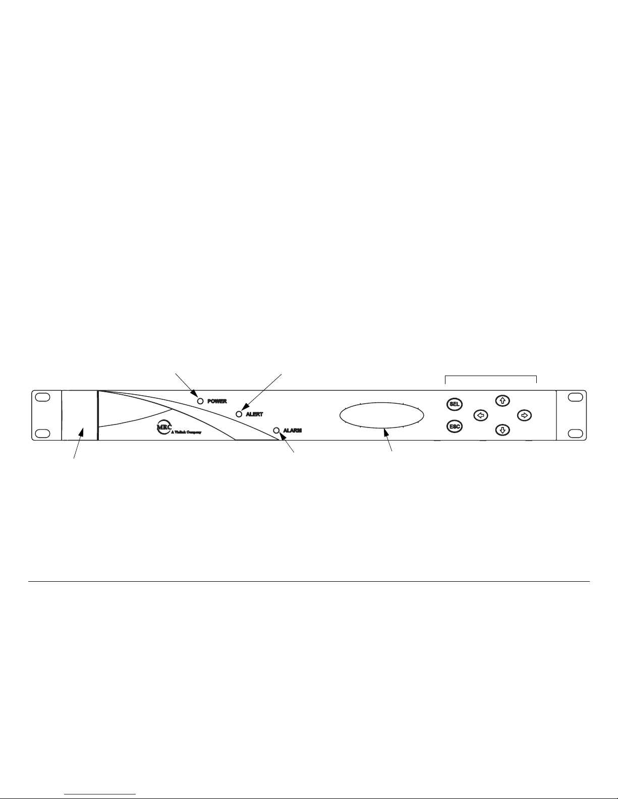
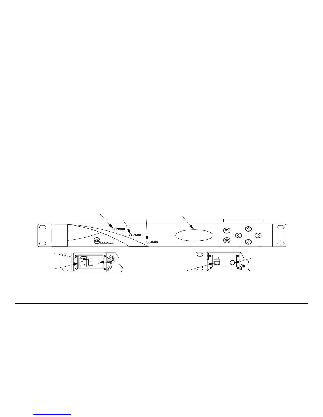
General The front panel of all MRX4000 PLUS configurations
(Figure 2-2 on page 2-3) are identical and contain a POWER
LED, an ALERT LED, an ALARM LED, an alphanumeric
display, and six function switches. The front panel also contains
an RS-232 connector, located behind an access cover, to
provide interface connections to a Microsoft Windows-based PC.
Product Description 2-3MRX4000 PLUS Operator’s Guide/
Technical Reference Manual
The rear panels of the various MRX4000 PLUS configurations
contain the I/O connectors, the input power connector, the power
switch, and power fuses.
Controls, indicators, and connectors contained on all
configurations of the MRX4000 PLUS are identified and
described in the “Routine Operation” Chapter on page 3-1.
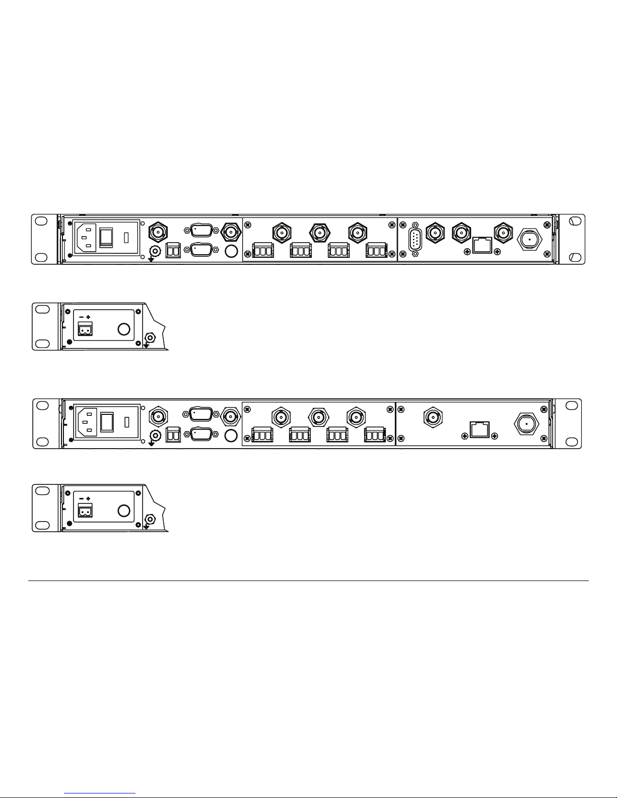
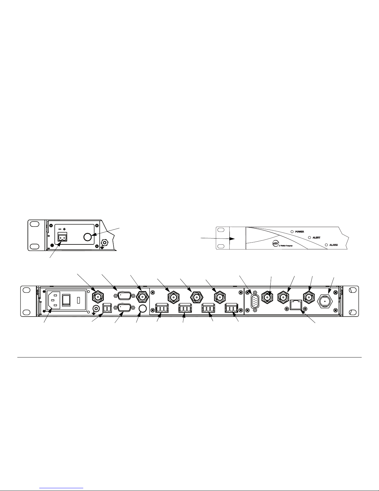
Configurations The rear panels of the MRX4000 PLUS Digital
MPEG/COFDM, Analog + Digital MPEG/COFDM/FMR NTSC,
and Digital MPEG/COFDM/FMR PAL configurations are identical
and are shown in Figure 2-3 on page 2-4.
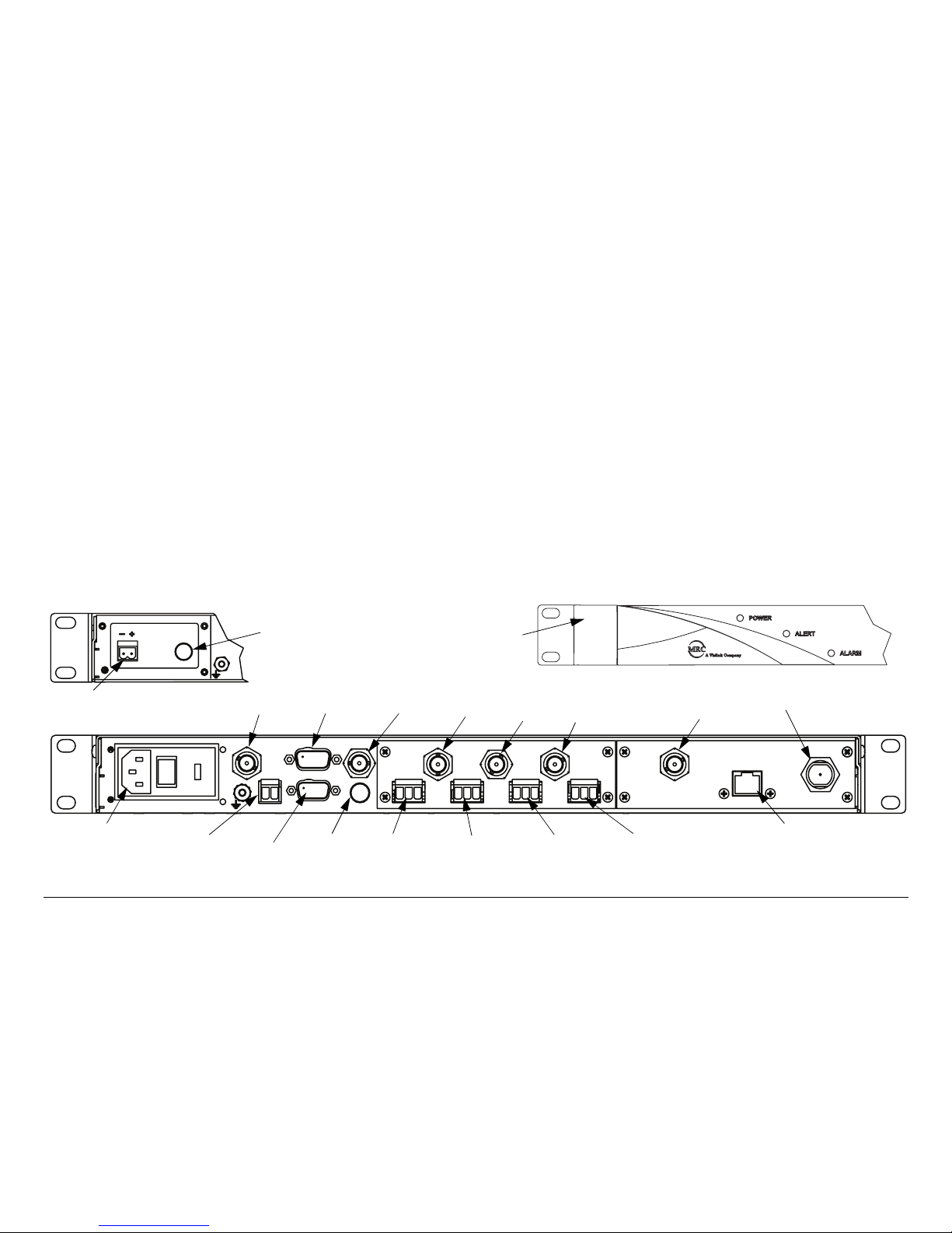
The rear panels of the MRX4000 PLUS Analog FMR NTSC and
FMR PAL configurations are identical and are shown in Figure 2-
4 on page 2-4.
Figure 2-2: MRX4000 PLUS Front Panel View
RS-232 Connector
(Located behind
access cover)
POWER LED ALERT LED
ALARM LED
Alphanumeric
Display
Function Switches
Product Description 2-4MRX4000 PLUS Operator’s Guide/
Technical Reference Manual
Figure 2-3: MRX4000 PLUS Digital and Analog + Digital Configurations - Rear View
Figure 2-4: MRX4000 PLUS Analog Only Configurations - Rear View
POWER IN
IF IN
- +
+24V OUT
SUM ALARM
FUSE
IF OUT
1
2
34
VIDEO OUT
VIDEO MON
AUDIO
BB OUT
WAYSIDE
900 MHZ SDI OUT
ASI OUT
CONTROL
RF
IN
SERIAL/LQ
POWER IN
FUSE
AC Power Option
DC Power Option
POWER IN
IF IN
+24V OUT
- +
SUM ALARM
FUSE
IF OUT
VIDEO OUT
VIDEO MON
AUDIO
1
2
3
4
BB OUT
900 MHZ
CONTROL
RF
IN
SERIAL/LQ
POWER IN
FUSE
AC Power Option
DC Power Option

Product Description 2-5MRX4000 PLUS Operator’s Guide/
Technical Reference Manual
2.2.4 Power Options
The flexible architecture of the MRX4000 PLUS allows the
various configurations to operate on the following AC and DC
power sources:
• 120/240 VAC, 50/60 Hz
• +24 or +48 VDC
• -24 or -48 VDC
Fuse ratings for the optional AC and DC power sources are
listed in Table 2-1.
Refer to the “Installation” Chapter on page 6-1 (part of the
MRX4000 PLUS Technical Reference Manual only) for additional
information.
2.2.5 Mounting and Deployment Options
The MRX4000 PLUS is mounted in a standard 19-inch (48.3 cm)
rack for fixed site operations.
For more details on installation of the MRX4000 PLUS in various
applications, see the “Installation” Chapter on page 6-1 (part of
the MRX4000 PLUS Technical Reference Manual only).
Table 2-1: Fuse Ratings
Operating Voltage Fuse Rating
240 VAC, 50/60 Hz 1.0A, 250V, AGC, Fast Blow
120 VAC, 50/60 Hz 2.0A, 250V, AGC, Fast Blow
48 VDC 5.0A, 250V, 5 x 20 mm
24 VDC 10.0A, 250V, 5 x 20 mm
+24 VDC (Output) 1.0 A, 250V, 5 x 20 mm, Slow Blow
2.2.6 System Operation
The MRX4000 PLUS offers two levels of system operation,
designed to match the needs of different personnel.
For the field operator, the MRX4000 PLUS has up to 9 Presets
that can be selected from the front panel. Each Preset controls
key parameters such as modulation, frequency, and audio and
video settings. Additional front panel-controlled settings are
dependent upon the configuration options contained in your
MRX4000 PLUS. See ”Using the MRX4000 PLUS Screens” on
page 3-8 for additional information.
For the advanced operator and technical staff, the MRX4000
PLUS Configuration Utility (Configurator) software allows
complete control of all parameters in your MRX4000 PLUS. The
Configurator software runs on a Microsoft Windows-based PC
and connects to the MRX4000 PLUS front panel RS-232
connector via an RS-232 serial interface cable.
Interfacing a PC to the MRX4000 PLUS in a connected system
gives you complete control of the unit. You can read the current
settings, program new settings, or return the unit to its factory
default settings. The Configurator software automatically detects
what hardware is installed in the system and applies the
appropriate configuration, regardless of the hardware being
configured.

Product Description 2-6MRX4000 PLUS Operator’s Guide/
Technical Reference Manual
2.3 MRX4000 PLUS Configurations
MRX4000 PLUS configuration block diagrams are provided in
the following sections.
For details on connections between the MRX4000 PLUS and
receiver components, refer to the “Installation” Chapter on
page 6-1 (part of the MRX4000 PLUS Technical Reference
Manual only).
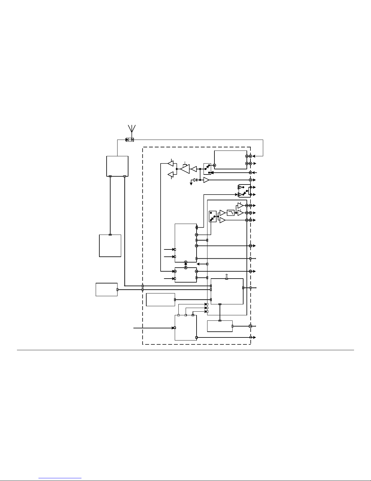
2.3.1 MPEG/COFDM Digital Configuration
The MRX4000 PLUS MPEG/COFDM Digital configuration block
diagram is shown in Figure 2-5 on page 2-7.
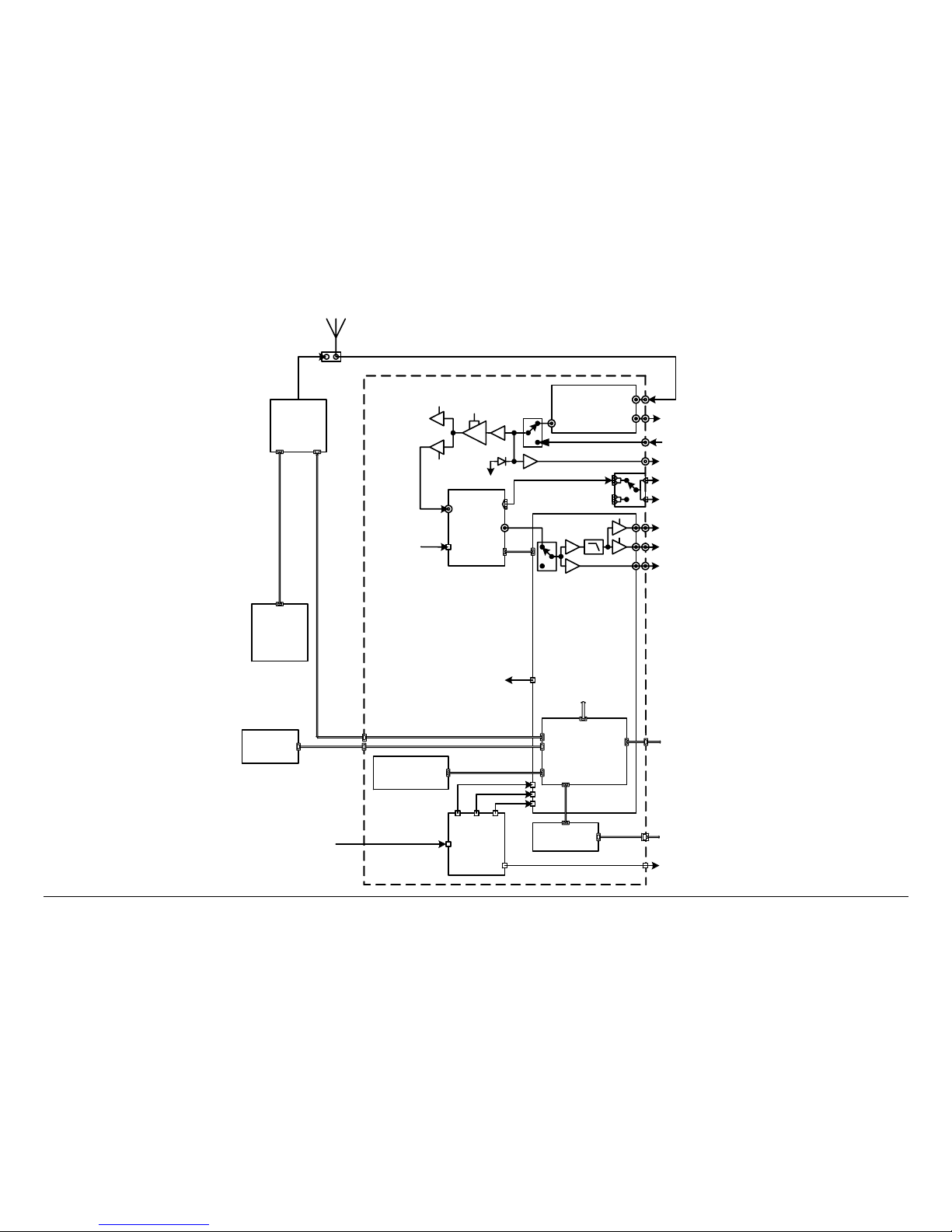
2.3.2 FMR NTSC/PAL Analog Configuration
The MRX4000 PLUS FMR NTSC/PAL Analog Configuration
Block Diagram is shown in Figure 2-6 on page 2-8.
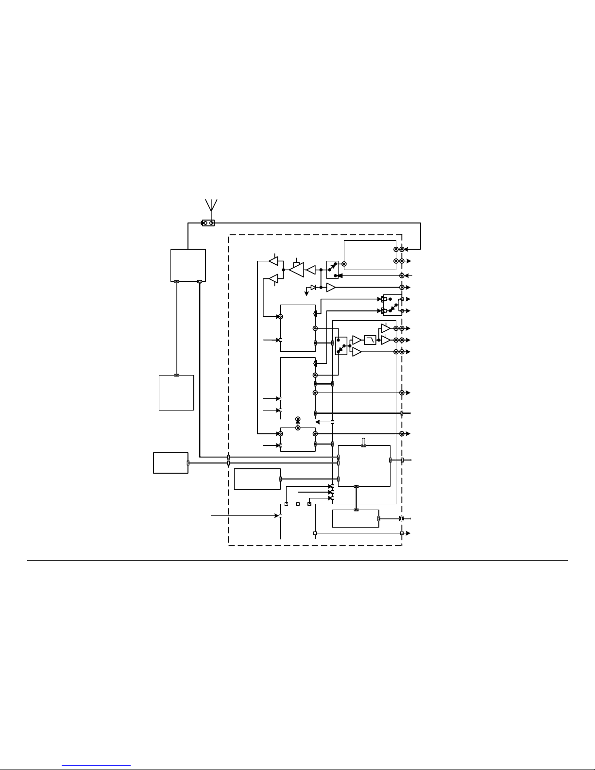
2.3.3 MPEG/COFDM/FMR NTSC/PAL Digital +
Analog Configuration
The MRX4000 PLUS MPEG/COFDM/FMR NTSC/PAL Analog +
Digital Configuration Block Diagram is shown in Figure 2-7 on
page 2-9.
2.4 For More Information
Additional detailed technical information about the MRX4000
PLUS is contained in the MRX4000 PLUS Technical Reference
Manual. Specific topics contained in the MRX4000 PLUS
Technical Reference Manual are listed below:
Topic Chapter
Changing settings using
the Configuration Utility
software
See ”Advanced Operation”
on page 5-1
Installation See ”Installation” on page 6-
1
Connections to other
equipment
See ”Installation” on page 61
Supported Repairs See ”Repair” on page 7-1
Repair Parts See ”Replacement Parts” on
page 8-1
Block Diagram See ”Theory of Operation”
on page 9-1
Product Description 2-7MRX4000 PLUS Operator’s Guide/
Technical Reference Manual
Figure 2-5: MRX4000 PLUS MPEG/COFDM Digital Configuration Block Diagram
ENG
Master
Controller
MC-17
Slave
Control
ASC140/
S750
COFDM
MPEG
RF Front End
Modules
BB
Video
Audio (Digital)
ASI
ASI
SDI
Microcontroller
PC / Laptop
Computer
D
i
g
i
t
a
l
-
1
0
d
B
m
RF Signal
IF OUT
AUDIO 1 - 2
BB OUT
VIDEO MON
VIDEO OUT
ASI OUT
SDI OUT
Remote Serial Interface To Slave Control
SUM ALARM
RS-232
+24 V OUT
DCC Board
Remote Control Connection
WAYSIDE
Wayside
Control
Cable
AGC
-10 dBm
~ 20 dB
+5.5
VDC
+5.5
VDC
IF Level
Monitor
IF Input
(70 MHz)
AUDIO 3 - 4
Data
Control
Data
Control
Data
Control
Front Panel
Control / Display
Data Comm. & Control
Video Signal Switch
(Analog/Digital)
IF IN
DC Power
Supply
+5.5 V
+12 V
-12 V
RF IN
+5.5 VDC
+/- 12
VDC
900 MHZ
SERIAL/LQ
(70 MHz)
Ethernet Card
CONTROL
(Future Op tion Not Currently
Active)
120/240 VAC 50/60 Hz
OR
+/-24 or +/-48 VD C
POWER IN
Product Description 2-8MRX4000 PLUS Operator’s Guide/
Technical Reference Manual
Figure 2-6: MRX4000 PLUS FMR NTSC/PAL Analog Configuration Block Diagram
FMR
ENG
Master
Controller
MC-17
Slave
Control
ASC140/
S750
RF Front End
Modules
Microcontroller
PC / Laptop
Computer
0 to +5
dBm
RF Signal
+5.5
VDC
IF OUT
AUDIO 1 - 2
BB OUT
VIDEO MON
VIDEO OUT
Remote Serial Interface To Slave Control
SUM ALARM
RS-232
+24 V OUT
DCC Board
Remote Control Connection
Audio (Analog)
Control
Cable
AGC
0 to +5 dBm
~ 20 dB
IF Level
Monitor
IF Input
(70 MHz)
AUDIO 3 - 4
BB
Video
Data
Control
Data
Control
Front Panel
Control / Display
Data Comm. & Control
IF IN
DC Power
Supply
+5.5 V
+12 V
-12 V
RF IN
+5.5 VDC
900 MHZ
SERIAL/LQ
(70 MHz)
Ethernet Card
CONTROL
(Future Option Not Currently
Active)
120/240 VAC 50/60 Hz
OR
+/-24 or +/-48 VDC
POWER IN
Product Description 2-9MRX4000 PLUS Operator’s Guide/
Technical Reference Manual
Figure 2-7: MRX4000 PLUS MPEG/COFDM/FMR NTSC/PAL Digital + Analog Configuration Block Diagram
FMR
ENG
Master
Controller
MC-17
Slave
Control
ASC140/
S750
COFDM
MPEG
RF Front End
Modules
BB
Video
Audio (Digital)
ASI
ASI
SDI
Microcontroller
PC / Laptop
Computer
0 to +5
dBm
D
i
g
i
t
a
l
-
1
0
d
B
m
RF Signal
+5.5
VDC
IF OUT
AUDIO 1 - 2
BB OUT
VIDEO MON
VIDEO OUT
ASI OUT
SDI OUT
Remote Serial Interface To Slave Control
SUM ALARM
RS-232
+24 V OUT
DCC Board
Remote Control Connection
Audio (Analog)
WAYSIDE
Wayside
Control
Cable
AGC
0 to +5 dBm
-10 dBm
~ 20 dB
+5.5
VDC
+5.5
VDC
IF Level
Monitor
IF Input
(70 MHz)
AUDIO 3 - 4
BB
Video
Data
Control
Data
Control
Data
Control
Data
Control
Front Panel
Control / Display
Data Comm. & Control
Video Signal Switch
(Analog/Digital)
IF IN
Audio Signal Switch
(Analog/Digital)
DC Power
Supply
+5.5 V
+12 V
-12 V
RF IN
+5.5 VDC
+/- 12
VDC
900 MHZ
SERIAL/LQ
(70 MHz)
Ethernet Card
CONTROL
(Future Option Not Currently
Active)
120/240 VAC 50/60 Hz
OR
+/-24 or +/-48 VDC
POWER IN

Product Description 2-10MRX4000 PLUS Operator’s Guide/
Technical Reference Manual
This page intentionally left blank.

3
Routine Operation 3-1MRX4000 PLUS Operator’s Guide/
Technical Reference Manual
Routine Operation
3.1 Chapter Overview
This chapter provides basic information that will enable you to
operate your MRX4000 PLUS High Performance Analog +
Digital Integrated Receiver Decoder (IRD) (MRX4000 PLUS).
Here are the topics covered:
Topic Page
Overview of Controls, Indicators and Connectors 3-1
Controls and Indicators 3-1
MRX4000 PLUS Digital and Digital + Analog
Configuration Connectors
3-3
MRX4000 PLUS Analog Configuration
Connectors
3-5
Preparing for Operation 3-7
Fixed or Mobile Installation 3-7
Powering the MRX4000 PLUS 3-7
Using the MRX4000 PLUS Screens 3-8
Overview 3-8
Menu Configurations 3-11
Main Screen 3-11
Cursors 3-11
Accessing Menus 3-13
Monitoring Operations 3-13
Monitor/Change MPEG Settings 3-13
Monitor/Change COFDM Settings 3-28
Monitor/Change FMR Settings 3-37
Information on settings made with the MRX4000 PLUS
Configuration Utility (Configurator) software can be found in
the “Advanced Operation” Chapter on page 5-1 (part of the
MRX4000 PLUS Technical Reference Manual only).
See ”Front Panel vs. Configurator Software” on page 3-71 for a
summary of settings that can be made with the front panel
control switches and which settings can be made using the
Configurator software.
3.2 Overview of Controls, Indicators
and Connectors
This section describes the controls, indicators, and connectors
contained on the MRX4000 PLUS.
3.2.1 Controls and Indicators
Controls and indicators contained on the MRX4000 PLUS are
identified and described below. Topics covered are as follows:
Monitor/Change MRX4000 PLUS RF/IF Section
Settings
3-48
Monitor/Change System Menu Options 3-65
Front Panel vs. Configurator Software 3-71
Topic Page
Rear Panel Input Power Assembly and Fuse 3-2
POWER LED 3-2
ALERT LED 3-2
ALARM LED 3-2
Alphanumeric Display 3-2
Keypad Switches 3-2
Routine Operation 3-2 Routine Operation 3-2MRX4000 PLUS Operator’s Guide/
Technical Reference Manual
Each of the controls and indicators are described in more detail
in the following paragraphs. Controls and indicators contained
on all configurations of the MRX4000 PLUS are identical and are
identified in Figure 3-1.
Rear Panel Input Power Assembly and Fuse The power
switch (AC power option only) is used to control application of
power to the MRX4000 PLUS. The DC power option does not
contain a power switch. The input power assembly also contains
the input power fuse and the AC/DC power connector.
POWER LED The green POWER LED is illuminated when
power is applied to the unit and the power switch (AC power
option only) is set to on ( I ).
ALERT LED The amber ALERT LED will illuminate when
system errors are present that do not cause the system to lose
service.
ALARM LED The red ALARM LED will illuminate when system
errors are present that cause the system to lose service.
Alphanumeric Display The alphanumeric display provides the
user interface to enable local control of the MRX4000 PLUS and
to provide full monitoring capability for the system. Additional
control of the system is achieved using the Microsoft Windows
PC-based Configurator software.
Keypad Switches The keypad switches provide user inputs to
control the menu system that appears on the alphanumeric
display. Four directional arrow keys, a SEL (Select) key, and an
ESC (Escape) key are used to navigate the MRX4000 PLUS
menus and to modify the MRX4000 PLUS settings.
Figure 3-1: MRX4000 PLUS Controls and Indicators
POWER IN
IF IN
ALERT
LED
POWER
LED
ALARM
LED
Alphanumeric
Display
Keypad
Switches
Front View
Rear View
Power
Switch
Fuse (Located
Under Safety
Cover)
POWER IN
FUSE
Rear View
AC Power
Option
DC Power
Option
Fuse

Routine Operation 3-3MRX4000 PLUS Operator’s Guide/
Technical Reference Manual
3.2.2 MRX4000 PLUS Digital and Digital + Analog
Configuration Connectors
Connectors contained on the Digital MRX4000 PLUS MPEG/
COFDM, Digital + Analog MPEG/COFDM/FMR NTSC, and
MPEG/COFDM/FMR PAL configurations are identical. These
connectors are identified in Figure 3-2 on page 3-4 and are
described below. Connectors covered are as follows:
Topic Page
Front Panel RS-232 Connector 3-3
AC Power Connector with Fuse 3-3
DC Power Connector with Fuse 3-3
IF IN Connector 3-3
SERIAL/LQ Connector 3-3
IF OUT Connector 3-3
VIDEO OUT Connector 3-3
VIDEO MON Connector 3-4
BB OUT Connector 3-4
SDI OUT Connector 3-5
900 MHZ Connector 3-4
WAYSIDE Connector 3-4
ASI OUT Connector 3-5
RF IN Connector 3-5
+24V OUT Connector 3-5
SUM ALARM Connector 3-5
FUSE 3-5
AUDIO 1 thru 4 Connectors 3-5
CONTROL Connector 3-5
Front Panel RS-232 Connector The RS-232 DB-9 male
connector, used to provide the interface between the MRX4000
PLUS and a Microsoft Windows-based PC when using the
Configurator software, is located behind an access cover on the
front panel. This connector is present on all configurations of the
MRX4000 PLUS.
The MRX4000 PLUS is configured through the RS-232
connector using the Microsoft Windows PC-based Configurator
software. For details, see the “Advanced Operation” Chapter on
page 5-1 (part of the MRX4000 PLUS Technical Reference
Manual only).
AC Power Connector with Fuse In the AC option, the AC
power connector provides connection to the removable external
power cable.
The AC power connector also contains an AC input power fuse.
DC Power Connector with Fuse In the DC option, the DC
power connector provides connection to the removable external
power cable.
The DC power connector also contains a DC input power fuse.
IF IN Connector The IF IN 75 ohm BNC female connector
provides the input connection for 70 MHz IF to the unit.
SERIAL/LQ Connector The SERIAL L/Q 9-pin female D-
connector provides remote serial control and also provides DC
voltages to monitor Link Quality (LQ) in the digital mode, or
Received Carrier Level (RCL) in the analog mode.
IF OUT Connector The IF OUT 75 ohm BNC female connector
provides the 70 MHz IF output signal.
VIDEO OUT Connector The VIDEO OUT 75 ohm BNC female
connector provides buffered video output selected either from
the FMR or MPEG modules. The video output is also routed via
Routine Operation 3-4 Routine Operation 3-4MRX4000 PLUS Operator’s Guide/
Technical Reference Manual
a video low pass filter (LPF) to remove audio subcarriers or
through a bypass filter for other applications.
VIDEO MON Connector The VIDEO MON 75 ohm BNC female
connector provides buffered video output selected either from
the FMR or MPEG modules. The video output is also routed via
a video low pass filter (LPF) to remove audio subcarriers or
through a bypass filter for other applications or for monitoring
purposes.
BB OUT Connector The BB OUT 75 ohm BNC female
connector provides baseband output unfiltered buffered video
from the FMR or MPEG modules for processing of audio
subcarriers.
WAYSIDE Connector The WAYSIDE 9-pin female D-connector
provides connection to MPEG decoder Wayside output data.
900 MHZ Connector The 900 MHZ 75 ohm BNC female
connector provides a spectrum analyzer output from the
MRX4000 PLUS for monitoring on a Troll Remote Control
System.
Figure 3-2: MRX4000 PLUS Digital and Digital + Analog Configuration Connectors
POWER IN
IF IN
- +
+24V OUT
SUM ALARM
FUSE
IF OUT
1
2
34
VIDEO OUT
VIDEO MON
AUDIO
BB OUT
WAYSIDE
900 MHZ SDI OUT
ASI OUT
CONTROL
RF
IN
SERIAL/LQ
Front View
RS-232 Connector
(Behind Access
Cover)
IF IN
SUM
ALARM
Rear View
IF OUT
VIDEO
OUT
Fuse
VIDEO
MON
BB
OUT
ASI
OUT
SDI
OUT
WAYSIDE
AUDIO 1
AUDIO 2
AUDIO 4
AUDIO 3
+24V OUT
RF IN
900 MHZ
CONTROL (Future
option - Not currently
active)
SERIAL/LQ
POWER IN
FUSE
DC Power
Connector
Fuse
AC Power
Connector
with Fuse

Routine Operation 3-5MRX4000 PLUS Operator’s Guide/
Technical Reference Manual
SDI OUT Connector The SDI OUT 75 ohm BNC female
connector provides SDI output from the MPEG module.
ASI OUT Connector The ASI OUT 75 ohm BNC female
connector provides ASI output from the COFDM module.
RF IN Connector The type “N” RF IN connector provides the
RF input from a remote antenna to the MRX4000 PLUS internal
Low Noise Converter.
+24V OUT Connector The +24V OUT 2-pin connector provides
constant (fused) +24 VDC output power for external LNB
applications.
SUM ALARM Connector The SUM ALARM 9-pin female D-
connector provides summary alarm data for common faults and
events.
FUSE The fuse provides protection for +24 VDC output power
for external LNB applications.
AUDIO 1 thru 4 Connectors The AUDIO 1 thru 4 3-pin output
connectors provide analog/digital switchable stereo audio signal
outputs from the FMR or MPEG modules.
CONTROL Connector The CONTROL RJ-45 connector
provides I/O connections for system control. (Future option - Not
currently active.)
3.2.3 MRX4000 PLUS Analog Configuration
Connectors
Connectors contained on the MRX4000 PLUS Analog FMR
NTSC and PAL configurations are identical. These connectors
are identified in Figure 3-3 on page 3-6 and are described below.
Connectors covered are as follows:
Topic Page
Front Panel RS-232 Connector 3-5
Front Panel RS-232 Connector The RS-232 DB-9 male
connector used to provide the interface between the MRX4000
PLUS Demodulator and the Microsoft Windows PC-based
Configurator software is located behind an access cover on the
front panel. This connector is present on all configurations of the
MRX4000 PLUS.
The MRX4000 PLUS is configured through the RS-232
connector using the Microsoft Windows PC-based Configurator
software. For details, see the “Advanced Operation” Chapter on
page 5-1 (part of the MRX4000 PLUS Technical Reference
Manual only).
AC Power Connector with Fuse In the AC option, the AC
power connector provides connection to the removable external
power cable. The AC power connector also contains an AC
input power fuse.
AC Power Connector with Fuse 3-5
DC Power Connector with Fuse 3-6
IF IN Connector 3-6
SERIAL/LQ Connector 3-6
IF OUT Connector 3-6
VIDEO OUT Connector 3-6
VIDEO MON Connector 3-6
BB OUT Connector 3-6
900 MHZ OUT Connector 3-6
RF IN Connector 3-7
+24V OUT Connector 3-7
SUM ALARM Connector 3-7
Fuse 3-7
AUDIO 1 thru 4 Connectors 3-7
CONTROL Connector 3-7
Routine Operation 3-6 Routine Operation 3-6MRX4000 PLUS Operator’s Guide/
Technical Reference Manual
DC Power Connector with Fuse In the DC option, the DC
power connector provides connection to the removable external
power cable. The DC power connector also contains a DC input
power fuse.
IF IN Connector The IF IN 75 ohm BNC female connector
provides the input connection for 70 MHz IF to the unit.
SERIAL/LQ Connector The SERIAL L/Q 9-pin female D-
connector provides remote serial control and also provides DC
voltages to monitor Link Quality (LQ) in the digital mode, or
Received Carrier Level (RCL) in the analog mode.
IF OUT Connector The IF OUT 75 ohm BNC female connector
provides the 70 MHz IF output signal.
VIDEO OUT Connector The VIDEO OUT 75 ohm BNC female
connector provides buffered video output selected from the FMR
module. The video output is also routed via a video low pass
filter (LPF) to remove audio subcarriers or through a bypass filter
for other applications.
VIDEO MON Connector The VIDEO MON 75 ohm BNC female
connector provides buffered video output selected from the FMR
module. The video output is also routed via a video low pass
filter (LPF) to remove audio subcarriers or through a bypass filter
for other applications or for monitoring purposes.
BB OUT Connector The BB OUT 75 ohm BNC female
connector provides baseband output unfiltered buffered video
from the FMR module for processing of audio subcarriers.
900 MHZ OUT Connector The 900 MHZ 75 ohm BNC female
connector provides a spectrum analyzer output for monitoring
on a Troll Remote Control System.
Figure 3-3: MRX4000 PLUS Analog Configuration Connectors
POWER IN
IF IN
+24V OUT
- +
SUM ALARM
FUSE
IF OUT
VIDEO OUT
VIDEO MON
AUDIO
1
2
3
4
BB OUT
900 MHZ
CONTROL
RF
IN
SERIAL/LQ
RS-232 Connector
(Behind Access
Cover)
Front View
Rear View
IF IN
IF OUT
VIDEO
OUT
VIDEO
MON
BB
OUT
AUDIO 1
AUDIO 2
AUDIO 3
AUDIO 4
+24V
SUM
ALARM
Fuse
900 MHZ
OUT
RF
CONTROL (Future
Option - Not currently
active)
SERIAL/LQ
POWER IN
FUSE
DC Power
Connector
Fuse
AC Power
Connector
with Fuse

Routine Operation 3-7MRX4000 PLUS Operator’s Guide/
Technical Reference Manual
RF IN Connector The type “N” RF IN connector provides the
RF input from a remote antenna to the MRX4000 PLUS internal
Low Noise Converter.
+24V OUT Connector The +24V OUT 2-pin connector provides
constant (fused) +24 VDC output power for external LNB
applications.
SUM ALARM Connector The SUM ALARM 9-pin female D-
connector provides summary alarm data for common faults and
events.
Fuse The fuse provides protection for +24 VDC output power
for external LNB applications.
AUDIO 1 thru 4 Connectors The AUDIO 1 thru 4 3-pin output
connectors provide analog/digital switchable stereo audio signal
outputs from the FMR module.
CONTROL Connector The CONTROL RJ-45 connector
provides Ethernet I/O connections for system control. (Future
option - Not currently active.)
3.3 Preparing for Operation
Each installation or deployment will have its own specific tasks
according to the application and the installed hardware.
3.3.1 Fixed or Mobile Installation
For fixed installations, the MRX4000 PLUS is mounted in a
standard 19-inch (48.3 cm) rack. The cabling is permanently
installed and power comes from the facility or site power source.
For mobile applications, the MRX4000 PLUS is usually mounted
in a bulkhead or compartment in a 19-inch (48.3 cm) rack. The
cabling is permanently installed and power comes from the
mobile power source.
3.3.2 Powering the MRX4000 PLUS
The steps required to power up and power down your MRX4000
PLUS are contained in the following steps.
Power Up
1. Verify the power cable is properly connected to the
rear panel power connector.
2. Verify all coaxial cables and cable connectors are
properly connected to the rear panel connectors.
3. Connect the MRX4000 PLUS power cable to AC or
DC power of the correct type, voltage and polarity, as
applicable to the power option contained on your unit.
If you are unsure of the power requirements or
connections, refer to the “Installation” chapter (part of
the MRX4000 PLUS Technical Reference Manual
only).
4. Verify the power source is turned on.
5. Set the MRX4000 PLUS rear panel power switch (AC
power option only) to on ( I ).
6. After approximately a 10 second delay following
application of power, the normal power-up sequence is
as follows:
- The front panel green POWER LED should illuminate .
- The alphanumeric display will illuminate and the Main
screen (Figure 3-4 on page 3-8) will be displayed.

Routine Operation 3-8MRX4000 PLUS Operator’s Guide/
Technical Reference Manual
Figure 3-4: Main Screen - Typical
Power Down
1. Set the MRX4000 PLUS rear panel power switch (AC
power option only) to off ( O ).
2. Set the power source off, as required.
3.4 Using the MRX4000 PLUS
Screens
Once the MRX4000 PLUS is set up using the Configurator
software and is powered up, you will be able to monitor and/or
change certain operating parameters through the use of the
menus displayed on the front panel alphanumeric display.
All options are dependent upon the actual configuration of your
MRX4000 PLUS and the Preset Operation Mode settings
established using the Configurator software. See ”Advanced
Operation” on page 5-1 for additional information on use of the
Configurator software (part of MRX4000 PLUS Technical
Reference Manual only).
The sections listed in Table 3-1 describe use of the menus.
>> MPEG Settings
FMR Settings
MRX4000+
COFDM Settings
3.4.1 Overview
As you use the MRX4000 PLUS, you will interact extensively
with the menus. The front panel alphanumeric display and
function keys provide you with the means to view and/or modify
operational parameters of the MRX4000 PLUS via use of the
menu pages displayed on the alphanumeric display.
The menu pages are organized in a hierarchy. The top level
menu is displayed upon power up of the unit and is returned to,
by default, when the user interface times out in approximately 30
seconds.
Menus will only display a maximum of three options. If a menu
contains more than three options, it will be necessary to scroll
through the options using the Up and Down arrow function keys.
The following are some points to make this easier.
The Main screen is your starting point for navigating through the
various menus. The Main screen provides access to the current
values of the Preset selected and the selected Preset options.
When power is applied to the MRX4000 PLUS, the Main screen
will be displayed. See Figure 3-5 on page 3-9.
Table 3-1: Using MRX4000 PLUS Menus
Topic Page
Overview 3-8
Menu Configurations 3-11
Main Screen 3-11
Cursors 3-11
Accessing Menus 3-13

Routine Operation 3-9MRX4000 PLUS Operator’s Guide/
Technical Reference Manual
Figure 3-5: Main Screen - Typical
The top level menu hierarchy is illustrated in Figure 3-6 on
page 3-10. From the top level menu page, the user descends
into the lower levels of the menu hierarchy until the operational
parameter required is reached.
Notes
If your MRX4000 PLUS does not contain an
MPEG, COFDM, RF/IF, or FMR module, or the
Preset operation mode selected does not include
MPEG, COFDM, RF/IF, or FMR, the >> cursor will
be replaced by a * cursor when the option is
selected.
Attempts to access those options will be ignored by
the firmware.
Illustrations reflecting individual menu hierarchy and the
associated options are listed in Table 3-2.
Table 3-2: Menu Hierarchy
Figure Page
MPEG Decoder Menu Map - Typical 3-15
COFDM Menu Map 3-29
FMR Settings Menu Map 3-38
>> MPEG Settings
FMR Settings
MRX4000+
COFDM Settings
Each menu page has multiple selections available, with one
selection per line. Once the user has navigated to the menu
page required, the user can observe or change an operating
parameter, as required. To observe or change a parameter,
different cursors are displayed (See ”Cursors” on page 3-11),
indicating different options available to the user.
The selections available on any menu page can exceed the
number of lines physically displayed. The front panel firmware
creates a box that surrounds the complete set of lines on any
menu page.
As the user scrolls through the set of menu item lines using the
Up and Down arrow keys, the firmware also moves the
surrounding box graphics to indicate to the user that options are
available that are off the alphanumeric display, i.e., either above
or below what is currently displayed (See ”Accessing Menus” on
page 3-13).
MRX4000 PLUS RF/IF Settings Menus Map 3-49
System Menus Map 3-66
Table 3-2: Menu Hierarchy (Continued)
Figure Page

Routine Operation 3-10MRX4000 PLUS Operator’s Guide/
Technical Reference Manual
Figure 3-6: Top Level Main Menu Hierarchy - Typical
MRX4000+
>> MPEG Settings
COFDM Settings
FMR Settings
RF/IF Settings
System Menus
COFDM Settings
> Bandwidth(A): 6
ModType: Unlk
FEC: Unlk
GuardInt: Unlk
Metrics:
FMR Settings
> VidFil: ON
VidDev: 3 MHz
1 SubFrq: 4830
1 En: OFF
1 Fil: OFF
1 De Emph: OFF
2 SubFrq: 5200
2 En: OFF
2 Fil: OFF
2 De Emph: OFF
3 SubFrq: 5800
3 En: OFF
3 Fil: OFF
3 De Emph: OFF
4 SubFrq: 6200
4 En: OFF
4 Fil: OFF
4 De Emph: OFF
System Menu
> Preset Menu
Active Errors
Error Log
System Info
System Reset
MPEG Decoder
> Color Bars: ON
Audio Out: Ana
NTSC Ped: OFF
BISS: OFF
Aud_A: Unlock
Aud_B: Unlock
Video: Bad
Chroma: 4:2:0
PktEr: 0E/S
Svc:
RF/IF Settings
* Freq: 2034.500
RCL: -150.0dBm
LQ: 0
Band: 2.0 GHz
ChannBW: 12MHz
Ch: +1
Filt: 15MHz LC
Squelch: -75dB
Mode: ANALOG
Source: IF
NTSC Radio Type
Option Only

Routine Operation 3-11MRX4000 PLUS Operator’s Guide/
Technical Reference Manual
3.4.2 Menu Configurations
The firmware determines which modules are contained in your
MRX4000 PLUS configuration upon power-up. The menus show
only those selections that are relevant to the user, based on the
current hardware configuration and Configurator software
settings.
Only options that are meaningful to the current chassis
configuration are displayed. In other words, if an optional
module is not contained in the MRX4000 PLUS, either the entire
menu page is not available or individual lines on a given menu
page are not available.
Additionally, if the Configurator software Preset operation mode
selected does not include MPEG, COFDM, RF/IF, or FMR,
attempts to access those options will be ignored by the system.
3.4.3 Main Screen
The Main screen is your starting point for navigating through the
various menus. The Main screen provides access to the current
values of the Preset selected and the selected Preset options.
When power is applied to the MRX4000 PLUS, the Main screen,
as shown in Figure 3-7, will be displayed.
Notes
If your MRX4000 PLUS does not contain an
MPEG, COFDM, RF/IF, or FMR module, or the
Preset operation mode selected does not include
MPEG, COFDM, RF/IF, or FMR, the >> cursor will
be replaced by a * cursor when the option is
selected.
Attempts to access those options will be ignored by
the firmware.
Figure 3-7: MRX4000 PLUS Main Screen - Typical
3.4.4 Cursors
The menu options will display several different cursors which will
change as various menu options are selected. The cursors are
identified as follows:
•The >> cursor, displayed to the left of a menu option,
indicates the option contains a sub-menu when selected.
Selecting that option, using the arrow keys and/or SEL
key, will bring you to the sub-menu.
For example, selecting >> MPEG Settings from the
Main screen menu, as shown in Figure 3-8, will bring you
to the MPEG Decoder sub-menu options, as shown in
Figure 3-9.
Figure 3-8: Main Screen Menu - Typical
Figure 3-9: MPEG Decoder Menu Options - Typical
>> MPEG Settings
FMR Settings
MRX4000+
COFDM Settings
>> MPEG Settings
FMR Settings
MRX4000+
COFDM Settings
> Color Bars: ON
NTSC Ped: OFF
MPEG Decoder
Audio Out: Ana

Routine Operation 3-12MRX4000 PLUS Operator’s Guide/
Technical Reference Manual
•The > cursor indicates the menu item selected contains
options that can be changed using the arrow keys and the
SEL key.
•The ! cursor will be displayed when a > menu option is
selected for change. It will also be displayed while the
arrow keys are being used to make option selections.
After pressing the SEL key to select the option or value,
the ! cursor will change back to a > cursor after
approximately 7 seconds.
If no arrow keys are pressed within approximately 7
seconds, the ! cursor will change back to a > cursor, and
the original option or value will be displayed. The SEL
key must be pressed to store any changes when the !
cursor is displayed.
•The * cursor will be displayed for menu items that are
read-only indications, for items that are currently inactive,
or for options that are not installed in the chassis.
When the * cursor is displayed, the item selected may
only be changed using the Configurator software or by the
factory.
If you press the SEL key when the * cursor is displayed,
the display will become locked on that screen to allow
you to observe status changes, i.e., to allow you to
monitor packet errors, etc. Pressing the ESC key unlocks
the display and returns you to the Main screen.
Changing Operating Parameters When the cursor is on an
operational parameter menu line that the user wishes to change,
and the SEL or Right arrow key is pressed, the cursor will
change and the firmware will enter the edit mode.
If the operating parameter requires values from a list of values,
the Up and Down keys provide the means to move through the
list of possible values. If the values are numeric, the Up, Down,
Left, and Right arrow keys provide the means to move through
the values in large or small steps.
The Up and Down keys move the values in larger steps, while
the Left and Right keys move the values in smaller steps. All
operational parameters have associated value ranges, defined
by upper and lower value limits.
There are two types of numeric values displayed: integers and
decimal. For example, if the operational parameter is a Preset
number, the keys allow selection of the Preset using the Preset
selection number.
When the correct value is located, the SEL key is pressed and
the value is recorded by the firmware and communicated to the
modules in the chassis. Further, the edit mode is exited and the
cursor changes from the ! cursor to the > cursor.
Menu Option Selections When making menu option
selections, the last option selected on the alphanumeric display
will be displayed when that menu is again accessed, unless
power has been removed from the unit.
When moving from menu to menu, it may be necessary to use
the arrow keys to move up and down through the menu options
to reach the option required.
Return to the Main Screen You can access the Main screen at
any time by pressing the ESC key until the Main screen is
displayed.
Default to Main Screen If you do not press the menu control
keys (SEL, ESC, or Left, Right, Up, or Down arrow keys) for
approximately 30 seconds, the display will automatically default
to the Main screen.

Routine Operation 3-13MRX4000 PLUS Operator’s Guide/
Technical Reference Manual
3.4.5 Accessing Menus
The option menus are accessed using the front panel SEL key
and/or the Left, Right, Up, and Down arrow keys.
To select the option required, press the Up or Down arrow keys
to move the cursor ( >> ) to the option required and press either
the SEL key or the Right arrow key. A typical Main screen menu
showing selection of the >> MPEG Settings option is shown in
Figure 3-10 and a typical MPEG Decoder menu is shown in
Figure 3-11.
Figure 3-10: Menu Options
Figure 3-11: MPEG Decoder Menu Options
Menus will display a maximum of three options. If the menus are
not as shown in Figure 3-10 or Figure 3-11, press the Up arrow
key until the option required is displayed.
For example, the Main screen menu also contains a System
Menus option that will be displayed by moving the cursor ( >> )
down using the Down arrow key. See Figure 3-12.
>> MPEG Settings
FMR Settings
MRX4000+
COFDM Settings
> Color Bars: ON
NTSC Ped: OFF
MPEG Decoder
Audio Out: Ana
Figure 3-12: Modulator Menu Additional Option
See “Monitoring Operations” to access individual Main screen
menu options .
3.5 Monitoring Operations
Once the MRX4000 PLUS is set up using the Configurator
software and is powered up, you will be able to check its
configuration and monitor its operation.
The following sections describe how to use the menus and how
to monitor the quality of the microwave link.
Here are the tasks described:
3.6 Monitor/Change MPEG Settings
If your MRX4000 PLUS configuration contains an MPEG
Decoder, the procedures listed in Ta bl e 3-3 on page 3-14 are
used to monitor or change internal MPEG Decoder parameters
or settings.
Topic Page
Monitor/Change MPEG Settings 3-13
Monitor/Change COFDM Settings 3-28
Monitor/Change FMR Settings 3-37
Monitor/Change MRX4000 PLUS RF/IF Section
Settings
3-48
Monitor/Change System Menu Options 3-65
MRX4000+
FMR Settings
>> System Menus

Routine Operation 3-14MRX4000 PLUS Operator’s Guide/
Technical Reference Manual
See Figure 3-13 on page 3-15 for the MPEG Decoder Menu
Map.
Table 3-3: Monitor/Change MPEG Settings
Topic Page
Monitor
Only
Change
Monitor/Change Color
Bars
3-16 ✔
Monitor/Change Audio
Output Mode Setting
3-17 ✔
Monitor/Change NTSC
Pedestal
3-18 ✔
Monitor/Change BISS
Settings
3-20 ✔
Monitor Audio A 3-21 ✔
Monitor Audio B 3-23 ✔
Monitor Video Status 3-24 ✔
Monitor Chroma Status 3-25 ✔
Monitor Service Name 3-26 ✔

Routine Operation 3-15MRX4000 PLUS Operator’s Guide/
Technical Reference Manual
Figure 3-13: MPEG Decoder Menu Map - Typical
MRX4000+
>> MPEG Settings
COFDM Settings
FMR Settings
RF/IF Settings
System Menus
MPEG Decoder
> Color Bars: ON
Audio Out: Ana
NTSC Ped: OFF
BISS: OFF
Vid Loss: Black
Aud A: Unlock
Aud B: Unlock
Video: Bad
Chroma: 4:2:0
Svc: XXXXXXX
MPEG Decoder
* Aud A: Unlock
MPEG Decoder
* Aud B: Unlock
MPEG Decoder
> NTSC Ped: OFF
MPEG Decoder
* Video: Bad
MPEG Decoder
> Color Bars: ON
Select ON or OFF.
Select ON or OFF.
Observe Aud A
status (Unlock,
Mono, or Stereo).
Observe Aud B
status (Unlock,
Mono, or Stereo).
Observe Video
status (Good or
Bad).
MPEG Decoder
* Svc: XXXXXXX
Observe Service
Name currently
being received or
No Service is
displayed.
MPEG Decoder
> Audio Out: Ana
Select Ana or Dig.
MPEG Decoder
> BISS: OFF
Select OFF, BISS-1,
or BISS-E.
MPEG Decoder
* Chrom a: 4:2:0
Observe Chroma
setting (4:2:0 or
4:2:2).
NTSC Radio Type
Option Only

Routine Operation 3-16MRX4000 PLUS Operator’s Guide/
Technical Reference Manual
Notes
Prior to monitoring or making any changes to the
MRX4000 PLUS MPEG Settings, you must
determine which Preset or Presets have been set
for the IF IN MPEG or RF IN MPEG operation
mode using the Configurator software.
The Preset operation modes should have been
recorded when the MRX4000 PLUS was
programmed using the Configurator software.
3.6.1 Monitor/Change Color Bars
To monitor/change Color Bars option settings, perform the
following steps:
1. Verify the MRX4000 PLUS is powered up.
2. Verify the Main screen (Figure 3-14) is displayed. If
the Main screen is not displayed, press the ESC key
until the Main screen is displayed.
Figure 3-14: Main Screen Menu
3. Press the Up arrow key, as required, to move the
cursor to the MPEG Settings option.
>> MPEG Settings
FMR Settings
MRX4000+
COFDM Settings
Note
If the cursor adjacent to the MPEG Settings option
is an asterisk ( * ), go to step 4; if the cursor
adjacent to the MPEG Settings option is a >>, go
to step 13.
4. Press the Down arrow key to move the cursor to the
Main screen System Menus option and press the
SEL key.
5. Observe the System Menu (Figure 3-15) is displayed.
Figure 3-15: System Menu
6. Press the Up or Down arrow keys, as required, to
select the >> Preset Menu option.
7. Observe the Preset Menu (Figure 3-16) is displayed.
Figure 3-16: Preset Menu - Typical
8. Press the Up or Down arrow keys, as required, to
select the > Recall Preset option.
9. Press the SEL key or Right arrow key and observe the
> cursor changes to a ! cursor.
10. Press the Up, Down, Right, or Left arrow keys, as
required, to select the Preset programmed for the IF
System Menu
>> Preset Menu
Active Errors
Error Log
Preset Menu
* #1:Preset 1
Save Settings
Recall Preset

Routine Operation 3-17MRX4000 PLUS Operator’s Guide/
Technical Reference Manual
IN MPEG or RF IN MPEG operation mode and press
the SEL key.
11. Press the ESC key until the Main screen is displayed.
12. Press the Up arrow key, as required, to select the
MPEG Settings option.
Notes
In the following step, if the cursor adjacent to the
MPEG Settings option is not a >> cursor, the
wrong Preset has been selected for the IF IN
MPEG or RF IN MPEG operation mode.
Repeat from step 4 to select the correct Preset.
13. Verify the cursor adjacent to the MPEG Settings
option is a >> cursor.
14. Press the SEL key or the Right arrow key and observe
the MPEG Decoder menu (Figure 3-17) is displayed.
Figure 3-17: MPEG Decoder Menu - Typical
15. Press the Up or Down arrow keys, as required, to
select the > Color Bars: option.
16. Press the Right arrow or SEL key and observe the >
cursor adjacent to the Color Bars: option changes to
a ! cursor.
17. Press the Right, Left, Up, or Down arrow keys, as
required, to select ON or OFF.
> Color Bars: ON
NTSC Ped: OFF
MPEG Decoder
Audio Out: Ana
18. Press the SEL key and observe the ! cursor changes
to a > cursor.
19. Press the ESC key until the Main screen is displayed.
3.6.2 Monitor/Change Audio Output Mode
Setting
To monitor/change the audio output mode (Audio Out:) setting,
perform the following steps:
1. Verify the MRX4000 PLUS is powered up.
2. Verify the Main screen (Figure 3-18) is displayed. If
the Main screen is not displayed, press the ESC key
until the Main screen is displayed.
Figure 3-18: Main Screen Menu
3. Press the Up arrow key, as required, to move the
cursor to the MPEG Settings option.
Note
If the cursor adjacent to the MPEG Settings option
is an asterisk ( * ), go to step 4; if the cursor
adjacent to the MPEG Settings option is a >>, go
to step 13.
4. Press the Down arrow key to move the cursor to the
Main screen System Menus option and press the
SEL key.
5. Observe the System Menu (Figure 3-19 on page 3-
18) is displayed.
>> MPEG Settings
FMR Settings
MRX4000+
COFDM Settings

Routine Operation 3-18MRX4000 PLUS Operator’s Guide/
Technical Reference Manual
Figure 3-19: System Menu
6. Press the Up or Down arrow keys, as required, to
select the >> Preset Menu option.
7. Observe the Preset Menu (Figure 3-20) is displayed.
Figure 3-20: Preset Menu - Typical
8. Press the Up or Down arrow keys, as required, to
select the > Recall Preset option.
9. Press the SEL key or Right arrow key and observe the
> cursor changes to a ! cursor.
10. Press the Up, Down, Right, or Left arrow keys, as
required, to select the Preset programmed for the IF
IN MPEG or RF IN MPEG operation mode and press
the SEL key.
11. Press the ESC key until the Main screen is displayed.
12. Press the Up arrow key, as required, to select the
MPEG Settings option.
System Menu
>> Preset Menu
Active Errors
Error Log
Preset Menu
* #1:Preset 1
Save Settings
Recall Preset
Notes
In the following step, if the cursor adjacent to the
MPEG Settings option is not a >> cursor, the
wrong Preset has been selected for the IF IN
MPEG or RF IN MPEG operation mode.
Repeat from step 4 to select the correct Preset.
13. Verify the cursor adjacent to the MPEG Settings
option is a >> cursor.
14. Press the SEL key or the Right arrow key and observe
the MPEG Decoder menu (Figure 3-21) is displayed.
Figure 3-21: MPEG Decoder Menu - Typical
15. Press the Up or Down arrow keys, as required, to
select the > Audio Out: option.
16. Press the Right arrow or SEL key and observe the >
cursor adjacent to the Audio Out: option changes to a
! cursor.
17. Press the Right, Left, Up, or Down arrow keys, as
required, to select Ana or Dig.
18. Press the SEL key and observe the ! cursor changes
to a > cursor.
19. Press the ESC key until the Main screen is displayed.
3.6.3 Monitor/Change NTSC Pedestal
To monitor/change NTSC Pedestal option settings on an NTSC
configuration MRX4000 PLUS only, perform the following steps:
> Color Bars: ON
NTSC Ped: OFF
MPEG Decoder
Audio Out: Ana

Routine Operation 3-19MRX4000 PLUS Operator’s Guide/
Technical Reference Manual
1. Verify the MRX4000 PLUS is powered up.
2. Verify the Main screen (Figure 3-22) is displayed. If
the Main screen is not displayed, press the ESC key
until the Main screen is displayed.
Figure 3-22: Main Screen Menu
3. Press the Up arrow key, as required, to move the
cursor to the MPEG Settings option.
Note
If the cursor adjacent to the MPEG Settings option
is an asterisk ( * ), go to step 4; if the cursor
adjacent to the MPEG Settings option is a >>, go
to step 13.
4. Press the Down arrow key to move the cursor to the
Main screen System Menus option and press the
SEL key.
5. Observe the System Menu (Figure 3-23) is displayed.
Figure 3-23: System Menu
6. Press the Up or Down arrow keys, as required, to
select the >> Preset Menu option.
>> MPEG Settings
FMR Settings
MRX4000+
COFDM Settings
System Menu
>> Preset Menu
Active Errors
Error Log
7. Observe the Preset Menu (Figure 3-24) is displayed.
Figure 3-24: Preset Menu - Typical
8. Press the Up or Down arrow keys, as required, to
select the > Recall Preset option.
9. Press the SEL key or Right arrow key and observe the
> cursor changes to a ! cursor.
10. Press the Up, Down, Right, or Left arrow keys, as
required, to select the Preset programmed for the IF
IN MPEG or RF IN MPEG operation mode and press
the SEL key.
11. Press the ESC key until the Main screen is displayed.
12. Press the Up arrow key, as required, to select the
MPEG Settings option.
Notes
In the following step, if the cursor adjacent to the
MPEG Settings option is not a >> cursor, the
wrong Preset has been selected for the IF IN
MPEG or RF IN MPEG operation mode.
Repeat from step 4 to select the correct Preset.
13. Verify the cursor adjacent to the MPEG Settings
option is a >> cursor.
14. Press the SEL key or the Right arrow key and observe
the MPEG Decoder menu (Figure 3-25 on page 3-20)
is displayed.
Preset Menu
* #1:Preset 1
Save Settings
Recall Preset

Routine Operation 3-20MRX4000 PLUS Operator’s Guide/
Technical Reference Manual
Figure 3-25: MPEG Decoder Menu - Typical
15. Press the Up or Down arrow keys, as required, to
select the > NTSC Ped: option.
16. Press the Right arrow or SEL key and observe the >
cursor adjacent to the NTSC Ped: option changes to a
! cursor.
17. Press the Right, Left, Up, or Down arrow keys, as
required, to select ON or OFF.
18. Press the SEL key and observe the ! cursor changes
to a > cursor.
19. Press the ESC key until the Main screen is displayed.
3.6.4 Monitor/Change BISS Settings
To monitor/change BISS settings, perform the following steps:
Notes
Basic Interoperable Scrambling System (BISS) is a
factory-configured option that must be ordered
when you order your MRX4000 PLUS. You must
have the BISS option enabled to perform the
following steps.
The BISS operating mode and associated
encryption key(s) must be programmed into the
MRX4000 PLUS using the Configurator software
before the following steps can be performed.
> Color Bars: ON
NTSC Ped: OFF
MPEG Decoder
Audio Out: Ana
1. Verify the MRX4000 PLUS is powered up.
2. Verify the Main screen (Figure 3-26) is displayed. If
the Main screen is not displayed, press the ESC key
until the Main screen is displayed.
Figure 3-26: Main Screen Menu
3. Press the Up arrow key, as required, to move the
cursor to the MPEG Settings option.
Note
If the cursor adjacent to the MPEG Settings option
is an asterisk ( * ), go to step 4; if the cursor
adjacent to the MPEG Settings option is a >>, go
to step 13.
4. Press the Down arrow key to move the cursor to the
Main screen System Menus option and press the
SEL key.
5. Observe the System Menu (Figure 3-27) is displayed.
Figure 3-27: System Menu
6. Press the Up or Down arrow keys, as required, to
select the >> Preset Menu option.
>> MPEG Settings
FMR Settings
MRX4000+
COFDM Settings
System Menu
>> Preset Menu
Active Errors
Error Log

Routine Operation 3-21MRX4000 PLUS Operator’s Guide/
Technical Reference Manual
7. Observe the Preset Menu (Figure 3-28) is displayed.
Figure 3-28: Preset Menu - Typical
8. Press the Up or Down arrow keys, as required, to
select the > Recall Preset option.
9. Press the SEL key or Right arrow key and observe the
> cursor changes to a ! cursor.
10. Press the Up, Down, Right, or Left arrow keys, as
required, to select the Preset programmed for the IF
IN MPEG or RF IN MPEG operation mode and press
the SEL key.
11. Press the ESC key until the Main screen is displayed.
12. Press the Up arrow key, as required, to select the
MPEG Settings option.
Notes
In the following step, if the cursor adjacent to the
MPEG Settings option is not a >> cursor, the
wrong Preset has been selected for the IF IN
MPEG or RF IN MPEG operation mode.
Repeat from step 4 to select the correct Preset.
13. Verify the cursor adjacent to the MPEG Settings
option is a >> cursor.
14. Press the SEL key or the Right arrow key and observe
the MPEG Decoder menu is displayed. See Figure 3-
29.
Preset Menu
* #1:Preset 1
Save Settings
Recall Preset
Figure 3-29: MPEG Decoder Menu - Typical
15. Press the Up or Down arrow keys, as required, to
select the > BISS: option.
16. Press the Right arrow or SEL key and observe the >
cursor adjacent to the BISS: option changes to a !
cursor.
17. Press the Right, Left, Up, or Down arrow keys, as
required, to select OFF, BISS-1, or BISS-E.
18. Press the SEL key and observe the ! cursor changes
to a > cursor.
19. Press the ESC key until the Main screen is displayed.
3.6.5 Monitor Audio A
To monitor Audio A (Aud A) status, perform the following steps:
1. Verify the MRX4000 PLUS is powered up.
2. Verify the Main screen (Figure 3-30) is displayed. If
the Main screen is not displayed, press the ESC key
until the Main screen is displayed.
Figure 3-30: Main Screen Menu
> Color Bars: ON
NTSC Ped: OFF
MPEG Decoder
Audio Out: Ana
>> MPEG Settings
FMR Settings
MRX4000+
COFDM Settings

Routine Operation 3-22MRX4000 PLUS Operator’s Guide/
Technical Reference Manual
3. Press the Up arrow key, as required, to move the
cursor to the MPEG Settings option.
Note
If the cursor adjacent to the MPEG Settings option
is an asterisk ( * ), go to step 4; if the cursor
adjacent to the MPEG Settings option is a >>, go
to step 13.
4. Press the Down arrow key to move the cursor to the
Main screen System Menus option and press the
SEL key.
5. Observe the System Menu (Figure 3-31) is displayed.
Figure 3-31: System Menu
6. Press the Up or Down arrow keys, as required, to
select the >> Preset Menu option.
7. Observe the Preset Menu (Figure 3-32) is displayed.
Figure 3-32: Preset Menu - Typical
8. Press the Up or Down arrow keys, as required, to
select the > Recall Preset option.
System Menu
>> Preset Menu
Active Errors
Error Log
Preset Menu
* #1:Preset 1
Save Settings
Recall Preset
9. Press the SEL key or Right arrow key and observe the
> cursor changes to a ! cursor.
10. Press the Up, Down, Right, or Left arrow keys, as
required, to select the Preset programmed for the IF
IN MPEG or RF IN MPEG operation mode and press
the SEL key.
11. Press the ESC key until the Main screen is displayed.
12. Press the Up arrow key, as required, to select the
MPEG Settings option.
Notes
In the following step, if the cursor adjacent to the
MPEG Settings option is not a >> cursor, the
wrong Preset has been selected for the IF IN
MPEG or RF IN MPEG operation mode.
Repeat from step 4 to select the correct Preset.
13. Verify the cursor adjacent to the MPEG Settings
option is a >> cursor.
14. Press the SEL key or the Right arrow key and observe
the MPEG Decoder menu (Figure 3-33) is displayed.
Figure 3-33: MPEG Decoder Menu - Typical
15. Press the Up or Down arrow keys, as required, to
select the * Aud_A: option.
16. Observe Aud_A: status (Unlock, Mono, or Stereo).
17. Press the ESC key until the Main screen is displayed.
> Color Bars: ON
NTSC Ped: OFF
MPEG Decoder
Audio Out: Ana

Routine Operation 3-23MRX4000 PLUS Operator’s Guide/
Technical Reference Manual
3.6.6 Monitor Audio B
To monitor Audio B (Aud B) status, perform the following steps:
1. Verify the MRX4000 PLUS is powered up.
2. Verify the Main screen (Figure 3-34) is displayed. If
the Main screen is not displayed, press the ESC key
until the Main screen is displayed.
Figure 3-34: Main Screen Menu
3. Press the Up arrow key, as required, to move the
cursor to the MPEG Settings option.
Note
If the cursor adjacent to the MPEG Settings option
is an asterisk ( * ), go to step 4; if the cursor
adjacent to the MPEG Settings option is a >>, go
to step 13.
4. Press the Down arrow key to move the cursor to the
Main screen System Menus option and press the
SEL key.
5. Observe the System Menu is displayed. See
Figure 3-35.
Figure 3-35: System Menu
>> MPEG Settings
FMR Settings
MRX4000+
COFDM Settings
System Menu
>> Preset Menu
Active Errors
Error Log
6. Press the Up or Down arrow keys, as required, to
select the >> Preset Menu option.
7. Observe the Preset Menu is displayed. See Figure 3-
36.
Figure 3-36: Preset Menu - Typical
8. Press the Up or Down arrow keys, as required, to
select the > Recall Preset option.
9. Press the SEL key or Right arrow key and observe the
> cursor changes to a ! cursor.
10. Press the Up, Down, Right, or Left arrow keys, as
required, to select the Preset programmed for the IF
IN MPEG or RF IN MPEG operation mode and press
the SEL key.
11. Press the ESC key until the Main screen is displayed.
12. Press the Up arrow key, as required, to select the
MPEG Settings option.
Notes
In the following step, if the cursor adjacent to the
MPEG Settings option is not a >> cursor, the
wrong Preset has been selected for the IF IN
MPEG or RF IN MPEG operation mode.
Repeat from step 4 to select the correct Preset.
13. Verify the cursor adjacent to the MPEG Settings
option is a >> cursor.
Preset Menu
* #1:Preset 1
Save Settings
Recall Preset

Routine Operation 3-24MRX4000 PLUS Operator’s Guide/
Technical Reference Manual
14. Press the SEL key or the Right arrow key and observe
the MPEG Decoder menu (Figure 3-37) is displayed.
Figure 3-37: MPEG Decoder Menu - Typical
15. Press the Up or Down arrow keys, as required, to
select the * Aud_B: option.
16. Observe Aud_B: status (Unlock, Mono, or Stereo).
17. Press the ESC key until the Main screen is displayed.
3.6.7 Monitor Video Status
The procedure required to monitor Video status is contained in
the following steps.
1. Verify the MRX4000 PLUS is powered up.
2. Verify the Main screen (Figure 3-38) is displayed. If
the Main screen is not displayed, press the ESC key
until the Main screen is displayed.
Figure 3-38: Main Screen Menu
3. Press the Up arrow key, as required, to move the
cursor to the MPEG Settings option.
> Color Bars: ON
NTSC Ped: OFF
MPEG Decoder
Audio Out: Ana
>> MPEG Settings
FMR Settings
MRX4000+
COFDM Settings
Note
If the cursor adjacent to the MPEG Settings option
is an asterisk ( * ), go to step 4; if the cursor
adjacent to the MPEG Settings option is a >>, go
to step 13.
4. Press the Down arrow key to move the cursor to the
Main screen System Menus option and press the
SEL key.
5. Observe the System Menu (Figure 3-39) is displayed.
Figure 3-39: System Menu
6. Press the Up or Down arrow keys, as required, to
select the >> Preset Menu option.
7. Observe the Preset Menu (Figure 3-40) is displayed.
Figure 3-40: Preset Menu - Typical
8. Press the Up or Down arrow keys, as required, to
select the > Recall Preset option.
9. Press the SEL key or Right arrow key and observe the
> cursor changes to a ! cursor.
System Menu
>> Preset Menu
Active Errors
Error Log
Preset Menu
* #1:Preset 1
Save Settings
Recall Preset

Routine Operation 3-25MRX4000 PLUS Operator’s Guide/
Technical Reference Manual
10. Press the Up, Down, Right, or Left arrow keys, as
required, to select the Preset programmed for the IF
IN MPEG or RF IN MPEG operation mode and press
the SEL key.
11. Press the ESC key until the Main screen is displayed.
12. Press the Up arrow key, as required, to select the
MPEG Settings option.
Notes
In the following step, if the cursor adjacent to the
MPEG Settings option is not a >> cursor, the
wrong Preset has been selected for the IF IN
MPEG or RF IN MPEG operation mode.
Repeat from step 4 to select the correct Preset.
13. Verify the cursor adjacent to the MPEG Settings
option is a >> cursor.
14. Press the SEL key or the Right arrow key and observe
the MPEG Decoder menu is displayed. See Figure 3-
41.
Figure 3-41: MPEG Decoder Menu - Typical
15. Press the Up or Down arrow keys, as required, to
select the * Video: option.
16. Observe Video: status (Good or Bad).
17. Press the ESC key until the Main screen is displayed.
> Color Bars: ON
NTSC Ped: OFF
MPEG D
ecoder
Audio Out: Ana
3.6.8 Monitor Chroma Status
The procedure to monitor Chroma status is contained in the
following steps:
1. Verify the MRX4000 PLUS is powered up.
2. Verify the Main screen (Figure 3-42) is displayed. If
the Main screen is not displayed, press the ESC key
until the Main screen is displayed.
Figure 3-42: Main Screen Menu
3. Press the Up arrow key, as required, to move the
cursor to the MPEG Settings option.
Note
If the cursor adjacent to the MPEG Settings option
is an asterisk ( * ), go to step 4; if the cursor
adjacent to the MPEG Settings option is a >>, go
to step 13.
4. Press the Down arrow key to move the cursor to the
Main screen System Menus option and press the
SEL key.
5. Observe the System Menu (Figure 3-43) is displayed.
Figure 3-43: System Menu
>> MPEG Settings
FMR Settings
MRX4000+
COFDM Settings
System Menu
>> Preset Menu
Active Errors
Error Log

Routine Operation 3-26MRX4000 PLUS Operator’s Guide/
Technical Reference Manual
6. Press the Up or Down arrow keys, as required, to
select the >> Preset Menu option.
7. Observe the Preset Menu (Figure 3-44) is displayed.
Figure 3-44: Preset Menu - Typical
8. Press the Up or Down arrow keys, as required, to
select the > Recall Preset option.
9. Press the SEL key or Right arrow key and observe the
> cursor changes to a ! cursor.
10. Press the Up, Down, Right, or Left arrow keys, as
required, to select the Preset programmed for the IF
IN MPEG or RF IN MPEG operation mode and press
the SEL key.
11. Press the ESC key until the Main screen is displayed.
12. Press the Up arrow key, as required, to select the
MPEG Settings option.
Notes
In the following step, if the cursor adjacent to the
MPEG Settings option is not a >> cursor, the
wrong Preset has been selected for the IF IN
MPEG or RF IN MPEG operation mode.
Repeat from step 4 to select the correct Preset.
13. Verify the cursor adjacent to the MPEG Settings
option is a >> cursor.
Preset Menu
* #1:Preset 1
Save Settings
Recall Preset
14. Press the SEL key or the Right arrow key and observe
the MPEG Decoder menu (Figure 3-45) is displayed.
Figure 3-45: MPEG Decoder Menu - Typical
15. Press the Up or Down arrow keys, as required, to
select the * Chroma: option.
16. Observe Chroma: status (4:2:0 or 4:2:2).
17. Press the ESC key until the Main screen is displayed.
3.6.9 Monitor Service Name
The procedure required to monitor the Service Name (Svc) of
the Preset is contained in the following steps.
1. Verify the MRX4000 PLUS is powered up.
2. Verify the Main screen (Figure 3-46) is displayed. If
the Main screen is not displayed, press the ESC key
until the Main screen is displayed.
Figure 3-46: Main Screen Menu
3. Press the Up arrow key, as required, to move the
cursor to the MPEG Settings option.
> Color Bars: ON
NTSC Ped: OFF
MPEG Decoder
Audio Out: Ana
>> MPEG Settings
FMR Settings
MRX4000+
COFDM Settings

Routine Operation 3-27MRX4000 PLUS Operator’s Guide/
Technical Reference Manual
Note
If the cursor adjacent to the MPEG Settings option
is an asterisk ( * ), go to step 4; if the cursor
adjacent to the MPEG Settings option is a >>, go
to step 13.
4. Press the Down arrow key to move the cursor to the
Main screen System Menus option and press the
SEL key.
5. Observe the System Menu (Figure 3-47) is displayed.
Figure 3-47: System Menu
6. Press the Up or Down arrow keys, as required, to
select the >> Preset Menu option.
7. Observe the Preset Menu (Figure 3-48) is displayed.
Figure 3-48: Preset Menu - Typical
8. Press the Up or Down arrow keys, as required, to
select the > Recall Preset option.
9. Press the SEL key or Right arrow key and observe the
> cursor changes to a ! cursor.
10. Press the Up, Down, Right, or Left arrow keys, as
required, to select the Preset programmed for the IF
System Menu
>> Preset Menu
Active Errors
Error Log
Preset Menu
* #1:Preset 1
Save Settings
Recall Preset
IN MPEG or RF IN MPEG operation mode and press
the SEL key.
11. Press the ESC key until the Main screen is displayed.
12. Press the Up arrow key, as required, to select the
MPEG Settings option.
Notes
In the following step, if the cursor adjacent to the
MPEG Settings option is not a >> cursor, the
wrong Preset has been selected for the IF IN
MPEG or RF IN MPEG operation mode.
Repeat from step 4 to select the correct Preset.
13. Verify the cursor adjacent to the MPEG Settings
option is a >> cursor.
14. Press the SEL key or the Right arrow key and observe
the MPEG Decoder menu (Figure 3-49) is displayed.
Figure 3-49: MPEG Decoder Menu - Typical
15. Press the Up or Down arrow keys, as required, to
select the * Svc: option.
16. Observe the selected Preset Service Name is
displayed.
17. Press the ESC key and observe the Main screen is
displayed.
> Color Bars: ON
NTSC Ped: OFF
MPEG Decoder
Audio Out: Ana

Routine Operation 3-28MRX4000 PLUS Operator’s Guide/
Technical Reference Manual
3.7 Monitor/Change COFDM Settings
If your MRX4000 PLUS configuration contains a COFDM option,
the procedures listed in Table 3-4 are used to monitor or change
internal COFDM parameters or settings.
See Figure 3-50 on page 3-29 for the COFDM Menu Map.
Table 3-4: Monitor/Change COFDM Settings
Topic Page
Monitor
Only
Change
Monitor/Change Bandwidth 3-30 ✔
Monitor Modulator Type 3-31 ✔
Monitor Forward Error
Correction
3-32 ✔
Monitor Guard Interval 3-34 ✔
Monitor COFDM Metrics 3-35 ✔

Routine Operation 3-29MRX4000 PLUS Operator’s Guide/
Technical Reference Manual
Figure 3-50: COFDM Menu Map
MRX4000+
MPEG Settings
>> COFDM Settings
FMR Settings
RF/IF Settings
System Menus
COFDM
> Bandwidth (A): 6
ModType: Unlk
FEC: Unlk
GuardInt: Unlk
Metrics
COFDM
* FEC: Unlk
COFDM
* GuardInt: Unlk
COFDM
* ModType: Unlk
COFDM
>> Metrics
COFDM
> Bandwidth (A): 6
Select 6, 7, 8, or
Auto.
Observe Unlk,
QPSK, 16QAM, or
64QAM.
Observe Unlk, 1/2,
2/3, 3/4, 5/6, or 7/8.
Observe Unlk, 1/32,
1/16, 1/8, or 1/4.
COFDM Metrics
* Viterbi BER:
* Pre: 1.000e+00
* Post: 7.817e-03
COFDM Metrics
* SNR: 00.00
COFDM Metrics
* Lock: Locked
Observe Locked or
Unlocked.
Observe signal to
noise ratio.
Observe Pre Viterbi
and Post Viterbi Bit
Error Rates.

Routine Operation 3-30MRX4000 PLUS Operator’s Guide/
Technical Reference Manual
Notes
Prior to monitoring or making any changes to the
MRX4000 PLUS COFDM Settings, you must
determine which Preset or Presets have been set
for the IF IN MPEG or RF IN MPEG operation
mode using the Configurator software.
The Preset operation modes should have been
recorded when the MRX4000 PLUS was
programmed using the Configurator software.
3.7.1 Monitor/Change Bandwidth
To monitor/change Bandwidth: option settings for the current
Preset, perform the following steps:
1. Verify the MRX4000 PLUS is powered up.
2. Verify the Main screen (Figure 3-51) is displayed. If
the Main screen is not displayed, press the ESC key
until the Main screen is displayed.
Figure 3-51: Main Screen Menu
3. Press the Up or Down arrow keys, as required, to
move the cursor to the COFDM Settings option.
Note
If the cursor adjacent to the COFDM Settings
option is an asterisk ( * ), go to step 4; if the cursor
adjacent to the COFDM Settings option is a >>, go
to step 13.
>> MPEG Settings
FMR Settings
MRX4000+
COFDM Settings
4. Press the Down arrow key to move the cursor to the
Main screen System Menus option and press the
SEL key.
5. Observe the System Menu (Figure 3-52) is displayed.
Figure 3-52: System Menu
6. Press the Up or Down arrow keys, as required, to
select the >> Preset Menu option.
7. Observe the Preset Menu (Figure 3-53) is displayed.
Figure 3-53: Preset Menu - Typical
8. Press the Up or Down arrow keys, as required, to
select the > Recall Preset option.
9. Press the SEL key or Right arrow key and observe the
> cursor changes to a ! cursor.
10. Press the Up, Down, Right, or Left arrow keys, as
required, to select the Preset programmed for the IF
IN MPEG or RF IN MPEG Operation Mode and press
the SEL key.
11. Press the ESC key until the Main screen is displayed.
12. Press the Up arrow key, as required, to select the
COFDM Settings option.
System Menu
>> Preset Menu
Active Errors
Error Log
Preset Menu
* #1:Preset 1
Save Settings
Recall Preset

Routine Operation 3-31MRX4000 PLUS Operator’s Guide/
Technical Reference Manual
Notes
In the following step, if the cursor adjacent to the
COFDM Settings option is not a >> cursor, the
wrong Preset has been selected for the IF IN
MPEG or RF IN MPEG operation mode.
Repeat from step 4 to select the correct Preset.
13. Verify the cursor adjacent to the COFDM Settings
option is a >> cursor.
14. Press the SEL key or the Right arrow key and observe
the COFDM menu (Figure 3-54) is displayed.
Figure 3-54: COFDM Menu - Typical
15. Press the Up or Down arrow keys, as required, to
select the > Bandwidth (A): option.
16. Press the Right arrow or SEL key and observe the >
cursor adjacent to the Bandwidth (A): option changes
to a ! cursor.
17. Press the Right, Left, Up, or Down arrow keys, as
required, to select 6, 7, 8, or Auto.
18. Press the SEL key and observe the ! cursor changes
to a > cursor.
19. Press the ESC key until the Main screen is displayed.
3.7.2 Monitor Modulator Type
To monitor Modulator Type (Mod Type:) option settings for the
current Preset, perform the following steps:
COFDM
> Bandwidth (A): 6
ModType: Unlk
FEC: Unlk
1. Verify the MRX4000 PLUS is powered up.
2. Verify the Main screen (Figure 3-55) is displayed. If
the Main screen is not displayed, press the ESC key
until the Main screen is displayed.
Figure 3-55: Main Screen Menu
3. Press the Up or Down arrow keys, as required, to
move the cursor to the COFDM Settings option.
Note
If the cursor adjacent to the COFDM Settings
option is an asterisk ( * ), go to step 4; if the cursor
adjacent to the COFDM Settings option is a >>, go
to step 13.
4. Press the Down arrow key to move the cursor to the
Main screen System Menus option and press the
SEL key.
5. Observe the System Menu is displayed. See
Figure 3-56.
Figure 3-56: System Menu
>> MPEG Settings
FMR Settings
MRX4000+
COFDM Settings
System Menu
>> Preset Menu
Active Errors
Error Log

Routine Operation 3-32MRX4000 PLUS Operator’s Guide/
Technical Reference Manual
6. Press the Up or Down arrow keys, as required, to
select the >> Preset Menu option.
7. Observe the Preset Menu (Figure 3-57) is displayed.
Figure 3-57: Preset Menu - Typical
8. Press the Up or Down arrow keys, as required, to
select the > Recall Preset option.
9. Press the SEL key or Right arrow key and observe the
> cursor changes to a ! cursor.
10. Press the Up, Down, Right, or Left arrow keys, as
required, to select the Preset programmed for the IF
IN MPEG or RF IN MPEG operation mode and press
the SEL key.
11. Press the ESC key until the Main screen is displayed.
12. Press the Up arrow key, as required, to select the
COFDM Settings option.
Notes
In the following step, if the cursor adjacent to the
COFDM Settings option is not a >> cursor, the
wrong Preset has been selected for the IF IN
MPEG or RF IN MPEG operation mode.
Repeat from step 4 to select the correct Preset.
13. Verify the cursor adjacent to the COFDM Settings
option is a >> cursor.
14. Press the SEL key or the Right arrow key and observe
the COFDM menu (Figure 3-58) is displayed.
Preset Menu
* #1:Preset 1
Save Settings
Recall Preset
Figure 3-58: COFDM Menu - Typical
15. Press the Up or Down arrow keys, as required, to
select the * ModType: option.
16. Observe ModType: indicates Unlk, QPSK, 16QAM,
or 64QAM.
17. Press the ESC key until the Main screen is displayed.
3.7.3 Monitor Forward Error Correction
The procedure required to monitor Forward Error Correction
(FEC) is contained in the following steps.
1. Verify the MRX4000 PLUS is powered up.
2. Verify the Main screen (Figure 3-59) is displayed. If
the Main screen is not displayed, press the ESC key
until the Main screen is displayed.
Figure 3-59: Main Screen Menu
3. Press the Up or Down arrow keys, as required, to
move the cursor to the COFDM Settings option.
COFDM
> Bandwidth (A): 6
ModType: Unlk
FEC: Unlk
>> MPEG Settings
FMR Settings
MRX4000+
COFDM Settings

Routine Operation 3-33MRX4000 PLUS Operator’s Guide/
Technical Reference Manual
Note
If the cursor adjacent to the COFDM Settings
option is an asterisk ( * ), go to step 4; if the cursor
adjacent to the COFDM Settings option is a >>, go
to step 13.
4. Press the Down arrow key to move the cursor to the
Main screen System Menus option and press the
SEL key.
5. Observe the System Menu (Figure 3-60) is displayed.
Figure 3-60: System Menu
6. Press the Up or Down arrow keys, as required, to
select the >> Preset Menu option.
7. Observe the Preset Menu (Figure 3-61) is displayed.
Figure 3-61: Preset Menu - Typical
8. Press the Up or Down arrow keys, as required, to
select the > Recall Preset option.
9. Press the SEL key or Right arrow key and observe the
> cursor changes to a ! cursor.
System Menu
>> Preset Menu
Active Errors
Error Log
Preset Menu
* #1:Preset 1
Save Settings
Recall Preset
10. Press the Up, Down, Right, or Left arrow keys, as
required, to select the Preset programmed for the IF
IN MPEG or RF IN MPEG operation mode and press
the SEL key.
11. Press the ESC key until the Main screen is displayed.
12. Press the Up arrow key, as required, to select the
COFDM Settings option.
Notes
In the following step, if the cursor adjacent to the
COFDM Settings option is not a >> cursor, the
wrong Preset has been selected for the IF IN
MPEG or RF IN MPEG operation mode.
Repeat from step 4 to select the correct Preset.
13. Verify the cursor adjacent to the COFDM Settings
option is a >> cursor.
14. Press the SEL key or the Right arrow key and observe
the COFDM menu (Figure 3-62) is displayed.
Figure 3-62: COFDM Menu - Typical
15. Press the Up or Down arrow keys, as required, to
select the * FEC: option.
16. Observe FEC: indicates Unlk, 1/2, 3/4, 5/6, or 7/8.
17. Press the ESC key until the Main screen is displayed.
COFDM
> Bandwidth (A): 6
ModType: Unlk
FEC: Unlk

Routine Operation 3-34MRX4000 PLUS Operator’s Guide/
Technical Reference Manual
3.7.4 Monitor Guard Interval
The procedure required to monitor Guard Interval (GuardInt)
status is contained in the following steps.
1. Verify the MRX4000 PLUS is powered up.
2. Verify the Main screen (Figure 3-63) is displayed. If
the Main screen is not displayed, press the ESC key
until the Main screen is displayed.
Figure 3-63: Main Screen Menu
3. Press the Up or Down arrow keys, as required, to
move the cursor to the COFDM Settings option.
Note
If the cursor adjacent to the COFDM Settings
option is an asterisk ( * ), go to step 4; if the cursor
adjacent to the COFDM Settings option is a >>, go
to step 13.
4. Press the Down arrow key to move the cursor to the
Main screen System Menus option and press the
SEL key.
5. Observe the System Menu (Figure 3-64) is displayed.
Figure 3-64: System Menu
>> MPEG Settings
FMR Settings
MRX4000+
COFDM Settings
System Menu
>> Preset Menu
Active Errors
Error Log
6. Press the Up or Down arrow keys, as required, to
select the >> Preset Menu option.
7. Observe the Preset Menu (Figure 3-65) is displayed.
Figure 3-65: Preset Menu - Typical
8. Press the Up or Down arrow keys, as required, to
select the > Recall Preset option.
9. Press the SEL key or Right arrow key and observe the
> cursor changes to a ! cursor.
10. Press the Up, Down, Right, or Left arrow keys, as
required, to select the Preset programmed for the IF
IN MPEG or RF IN MPEG operation mode and press
the SEL key.
11. Press the ESC key until the Main screen is displayed.
12. Press the Up arrow key, as required, to select the
COFDM Settings option.
Notes
In the following step, if the cursor adjacent to the
COFDM Settings option is not a >> cursor, the
wrong Preset has been selected for the IF IN
MPEG or RF IN MPEG operation mode.
Repeat from step 4 to select the correct Preset.
13. Verify the cursor adjacent to the COFDM Settings
option is a >> cursor.
Preset Menu
* #1:Preset 1
Save Settings
Recall Preset

Routine Operation 3-35MRX4000 PLUS Operator’s Guide/
Technical Reference Manual
14. Press the SEL key or the Right arrow key and observe
the COFDM menu (Figure 3-66) is displayed.
Figure 3-66: COFDM Menu - Typical
15. Press the Up or Down arrow keys, as required, to
select the * GuardInt: option.
16. Observe GuardInt: indicates Unlk, 1/32, 1/16, 1/8, or
1/4.
17. Press the ESC key until the Main screen is displayed.
3.7.5 Monitor COFDM Metrics
The procedure required to monitor COFDM Metrics is contained
in the following steps.
1. Verify the MRX4000 PLUS is powered up.
2. Verify the Main screen (Figure 3-67) is displayed. If
the Main screen is not displayed, press the ESC key
until the Main screen is displayed.
Figure 3-67: Main Screen Menu
3. Press the Up or Down arrow keys, as required, to
move the cursor to the COFDM Settings option.
COFDM
> Bandwidth (A): 6
ModType: Unlk
FEC: Unlk
>> MPEG Settings
FMR Settings
MRX4000+
COFDM Settings
Note
If the cursor adjacent to the COFDM Settings
option is an asterisk ( * ), go to step 4; if the cursor
adjacent to the COFDM Settings option is a >>, go
to step 13.
4. Press the Down arrow key to move the cursor to the
Main screen System Menus option and press the
SEL key.
5. Observe the System Menu (Figure 3-68) is displayed.
Figure 3-68: System Menu
6. Press the Up or Down arrow keys, as required, to
select the >> Preset Menu option.
7. Observe the Preset Menu (Figure 3-69) is displayed.
Figure 3-69: Preset Menu - Typical
8. Press the Up or Down arrow keys, as required, to
select the > Recall Preset option.
9. Press the SEL key or Right arrow key and observe the
> cursor changes to a ! cursor.
10. Press the Up, Down, Right, or Left arrow keys, as
required, to select the Preset programmed for the IF
System Menu
>> Preset Menu
Active Errors
Error Log
Preset Menu
* #1:Preset 1
Save Settings
Recall Preset

Routine Operation 3-36MRX4000 PLUS Operator’s Guide/
Technical Reference Manual
IN MPEG or RF IN MPEG operation mode and press
the SEL key.
11. Press the ESC key until the Main screen is displayed.
12. Press the Up arrow key, as required, to select the
COFDM Settings option.
Notes
In the following step, if the cursor adjacent to the
COFDM Settings option is not a >> cursor, the
wrong Preset has been selected for the IF IN
MPEG or RF IN MPEG operation mode.
Repeat from step 4 to select the correct Preset.
13. Verify the cursor adjacent to the COFDM Settings
option is a >> cursor.
14. Press the SEL key or the Right arrow key and observe
the COFDM menu (Figure 3-70) is displayed.
Figure 3-70: COFDM Menu - Typical
15. Press the Up or Down arrow keys, as required, to
select the >> Metrics: option.
16. Press the SEL or Right arrow key and observe the
COFDM Metrics menu (Figure 3-71) is displayed.
COFDM
> Bandwidth (A): 6
ModType: Unlk
FEC: Unlk
Figure 3-71: COFDM Metrics Menu - Typical
17. Press the Up or Down arrow keys, as required, to
select the * Lock: option.
18. Observe Lock: indicates Unlocked or Locked.
19. Observe the Signal to Noise Ratio SNR: indication.
20. Press the Down arrow key to select the * Post: option
as shown in Figure 3-72.
Figure 3-72: COFDM Viterbi Bit Error Rates - Typical
21. Observe the Pre Viterbi (Pre:) and Post Viterbi (Post)
Bit Error Rates (BER).
22. Press the ESC key until the Main screen is displayed.
COFDM Metrics
* Lock: Unlocked
SNR: 00.00
Viterbi BER:
COFDM Metrics
Viterbi BER:
Pre: 1.000e+00
* Post: 7.817e-03

Routine Operation 3-37MRX4000 PLUS Operator’s Guide/
Technical Reference Manual
3.8 Monitor/Change FMR Settings
If your MRX4000 PLUS configuration contains the FMR option,
the procedures listed in Table 3-5 are used to monitor or change
internal FMR parameters or settings.
See Figure 3-73 on page 3-38 for the FMR Settings Menu Map.
Table 3-5: Monitor/Change FMR Settings
Topic Page
Monitor/Change Video Filter 3-39
Monitor/Change Video Deviation 3-40
Monitor/Change Channel 1, 2, 3, or 4 SubCarrier Frequencies
3-42
Monitor/Enable/Disable Channel 1, 2, 3, or 4 3-43
Monitor/Enable/Disable Channel 1, 2, 3, or 4
Filtering
3-45
Monitor/Enable/Disable Channel 1, 2, 3, or 4 DeEmphasis
3-46

Routine Operation 3-38MRX4000 PLUS Operator’s Guide/
Technical Reference Manual
Figure 3-73: FMR Settings Menu Map
MRX4000+
MPEG Settings
COFDM Settings
>> FMR Settings
RF/IF Settings
System Menus
FMR
> 1 En: ON
FMR
> 1 Fil: ON
FMR
> 1 SubFrq: 4830
FMR
> 1 DeEmph: On
FMR
> VidDev: 3 MHz
FMR
> 2 SubFrq: 5200
FMR
> VidFil: ON
Select Video Filter On
or OFF.
Select Video Deviation
of 3 or 4 MHz.
Select Audio SubCarrier Frequency
4830, 5200, 5800,
6200, 6800, 7020,
7500, 8065, 8300, or
8590 KHz.
Select ON or OFF to
enable or disable
Channel 1 Audio SubCarrier.
Select ON or OFF to
enable or disable
Channel 1 Audio SubCarrier Filter.
Select ON or OFF to
enable or disable
Channel 1 Audio
Sub-Carrier Deemphasis.
Select Audio SubCarrier Frequency
4830, 5200, 5800,
6200, 6800, 7020,
7500, 8065, 8300, or
8590 KHz.
FMR
> 2 En: ON
Select ON or OFF to
enable or disable
Channel 2 Audio
Sub-Carrier.
FMR
> 2 Fil: ON
Select ON or OFF to
enable or disable
Channel 2 Audio
Sub-Carrier Filter.
FMR
> 2 DeEmph: ON
Select ON or OFF to
enable or disable
Channel 2 Audio
Sub-Carrier Deemphasis.
FMR
> 3 SubFrq: 5200
Select Audio SubCarrier Frequency
4830, 5200, 5800,
6200, 6800, 7020,
7500, 8065, 8300, or
8590 KHz.
FMR
> 3 En: ON
Select ON or OFF to
enable or disable
Channel 3 Audio
Sub-Carrier.
FMR
> 3 Fil: ON
Select ON or OFF to
enable or disable
Channel 3 Audio
Sub-Carrier Filter.
FMR
> 3 DeEmph: ON
Select ON or OFF to
enable or disable
Channel 3 Audio
Sub-Carrier Deemphasis.
FMR
> 4 SubFrq: 5200
Select Audio SubCarrier Frequency
4830, 5200, 5800,
6200, 6800, 7020,
7500, 8065, 8300, or
8590 KHz.
FMR
> 4 En: ON
Select ON or OFF to
enable or disable
Channel 4 Audio
Sub-Carrier.
FMR
> 4 Fil: ON
Select ON or OFF to
enable or disable
Channel 4 Audio
Sub-Carrier Filter.
FMR
> 4 DeEmph: ON
Select ON or OFF to
enable or disable
Channel 4 Audio
Sub-Carrier Deemphasis.
FMR Settings
> VidFil: ON
VidDev: 3 MHz
1 SubFreq: 4380
1 En: OFF
1 Fil: OFF
1 DeEmph: OFF
2 SubFreq: 5200
2 En: OFF
2 Fil: OFF
2 DeEmph: OFF
3 SubFreq: 5800
3 En: OFF
3 Fil: OFF
3 DeEmph: OFF
4 SubFreq: 6200
4 En: OFF
4 Fil: OFF
4 DeEmph: OFF

Routine Operation 3-39MRX4000 PLUS Operator’s Guide/
Technical Reference Manual
Notes
Prior to monitoring or making any changes to the
MRX4000 PLUS FMR Settings, you must
determine which Preset or Presets have been set
for the IF IN Analog or RF IN Analog operation
mode using the Configurator software.
The Preset operation modes should have been
recorded when the MRX4000 PLUS was
programmed using the Configurator software.
3.8.1 Monitor/Change Video Filter
The procedure required to enable or disable FMR video filtering
is contained in the following steps.
1. Verify the MRX4000 PLUS is powered up.
2. Verify the Main screen (Figure 3-74) is displayed. If
the Main screen is not displayed, press the ESC key
until the Main screen is displayed.
Figure 3-74: Main Screen Menu
3. Press the Up or Down arrow keys, as required, to
move the cursor to the FMR Settings option.
>> MPEG Settings
FMR Settings
MRX4000+
COFDM Settings
Note
If the cursor adjacent to the FMR Settings option
is an asterisk ( * ), go to step 4; if the cursor
adjacent to the FMR Settings option is a >>, go to
step 13.
4. Press the Down arrow key to move the cursor to the
Main screen System Menus option and press the
SEL key.
5. Observe the System Menu (Figure 3-75) is displayed.
Figure 3-75: System Menu
6. Press the Up or Down arrow keys, as required, to
select the >> Preset Menu option.
7. Observe the Preset Menu (Figure 3-76) is displayed.
Figure 3-76: Preset Menu - Typical
8. Press the Up or Down arrow keys, as required, to
select the > Recall Preset option.
9. Press the SEL key or Right arrow key and observe the
> cursor changes to a ! cursor.
10. Press the Up, Down, Right, or Left arrow keys, as
required, to select the Preset programmed for the IF
System Menu
>> Preset Menu
Active Errors
Error Log
Preset Menu
* #1:Preset 1
Save Settings
Recall Preset

Routine Operation 3-40MRX4000 PLUS Operator’s Guide/
Technical Reference Manual
IN Analog or RF IN Analog operation mode and press
the SEL key.
11. Press the ESC key until the Main screen is displayed.
12. Press the Up arrow key, as required, to select the FMR
Settings option.
Notes
In the following step, if the cursor adjacent to the
FMR Settings option is not a >> cursor, the wrong
Preset has been selected for the IF IN Analog or
RF IN Analog operation mode.
Repeat from step 4 to select the correct Preset.
13. Verify the cursor adjacent to the FMR Settings option
is a >> cursor.
14. Press the SEL key or the Right arrow key and observe
the FMR menu (Figure 3-77) is displayed.
Figure 3-77: FMR Menu - Typical
15. Press the Up or Down arrow keys, as required, to
select the > VidFil: option.
16. Press the Right arrow or SEL key and observe the >
cursor adjacent to the VidFil: option changes to a !
cursor.
17. Press the Right, Left, Up, or Down arrow keys, as
required, to select ON or OFF.
FMR
> VidFil: ON
VidDev: 4 MHz
1 SubFreq: 4830
18. Press the SEL key and observe the ! cursor changes
to a > cursor.
19. Press the ESC key until the Main screen is displayed.
3.8.2 Monitor/Change Video Deviation
The procedure required to change the FMR video deviation
frequency is contained in the following steps.
1. Verify the MRX4000 PLUS is powered up.
2. Verify the Main screen (Figure 3-78) is displayed. If
the Main screen is not displayed, press the ESC key
until the Main screen is displayed.
Figure 3-78: Main Screen Menu
3. Press the Up or Down arrow keys, as required, to
move the cursor to the FMR Settings option.
Note
If the cursor adjacent to the FMR Settings option
is an asterisk ( * ), go to step 4; if the cursor
adjacent to the FMR Settings option is a >>, go to
step 13.
4. Press the Down arrow key to move the cursor to the
Main screen System Menus option and press the
SEL key.
5. Observe the System Menu (Figure 3-79 on page 3-
41) is displayed.
>> MPEG Settings
FMR Settings
MRX4000+
COFDM Settings

Routine Operation 3-41MRX4000 PLUS Operator’s Guide/
Technical Reference Manual
Figure 3-79: System Menu
6. Press the Up or Down arrow keys, as required, to
select the >> Preset Menu option.
7. Observe the Preset Menu (Figure 3-80) is displayed.
Figure 3-80: Preset Menu - Typical
8. Press the Up or Down arrow keys, as required, to
select the > Recall Preset option.
9. Press the SEL key or Right arrow key and observe the
> cursor changes to a ! cursor.
10. Press the Up, Down, Right, or Left arrow keys, as
required, to select the Preset programmed for the IF
IN Analog or RF IN Analog operation mode and press
the SEL key.
11. Press the ESC key until the Main screen is displayed.
12. Press the Up arrow key, as required, to select the FMR
Settings option.
System Menu
>> Preset Menu
Active Errors
Error Log
Preset Menu
* #1:Preset 1
Save Settings
Recall Preset
Notes
In the following step, if the cursor adjacent to the
FMR Settings option is not a >> cursor, the wrong
Preset has been selected for the IF IN Analog or
RF IN Analog operation mode.
Repeat from step 4 to select the correct Preset.
13. Verify the cursor adjacent to the FMR Settings option
is a >> cursor.
14. Press the SEL key or the Right arrow key and observe
the FMR menu (Figure 3-81) is displayed.
Figure 3-81: FMR Menu - Typical
15. Press the Up or Down arrow keys, as required, to
select the > VidDev: option.
16. Press the Right arrow or SEL key and observe the >
cursor adjacent to the VidDev: option changes to a !
cursor.
17. Press the Right, Left, Up, or Down arrow keys, as
required, to select 3 or 4.
18. Press the SEL key and observe the ! cursor changes
to a > cursor.
19. Press the ESC key until the Main screen is displayed.
FMR
> VidFil: ON
VidDev: 4 MHz
1 SubFreq: 4830

Routine Operation 3-42MRX4000 PLUS Operator’s Guide/
Technical Reference Manual
3.8.3 Monitor/Change Channel 1, 2, 3, or 4 SubCarrier Frequencies
The procedure required to change sub-carrier frequencies for
Channels 1, 2, 3, or 4 is contained in the following steps.
1. Verify the MRX4000 PLUS is powered up.
2. Verify the Main screen (Figure 3-82) is displayed. If
the Main screen is not displayed, press the ESC key
until the Main screen is displayed.
Figure 3-82: Main Screen Menu
3. Press the Up or Down arrow keys, as required, to
move the cursor to the FMR Settings option.
Note
If the cursor adjacent to the FMR Settings option
is an asterisk ( * ), go to step 4; if the cursor
adjacent to the FMR Settings option is a >>, go to
step 13.
4. Press the Down arrow key to move the cursor to the
Main screen System Menus option and press the
SEL key.
5. Observe the System Menu (Figure 3-83) is displayed.
>> MPEG Settings
FMR Settings
MRX4000+
COFDM Settings
Figure 3-83: System Menu
6. Press the Up or Down arrow keys, as required, to
select the >> Preset Menu option.
7. Observe the Preset Menu (Figure 3-84) is displayed.
Figure 3-84: Preset Menu - Typical
8. Press the Up or Down arrow keys, as required, to
select the > Recall Preset option.
9. Press the SEL key or Right arrow key and observe the
> cursor changes to a ! cursor.
10. Press the Up, Down, Right, or Left arrow keys, as
required, to select the Preset programmed for the IF
IN Analog or RF IN Analog operation mode and press
the SEL key.
11. Press the ESC key until the Main screen is displayed.
12. Press the Up arrow key, as required, to select the FMR
Settings option.
System Menu
>> Preset Menu
Active Errors
Error Log
Preset Menu
* #1:Preset 1
Save Settings
Recall Preset

Routine Operation 3-43MRX4000 PLUS Operator’s Guide/
Technical Reference Manual
Notes
In the following step, if the cursor adjacent to the
FMR Settings option is not a >> cursor, the wrong
Preset has been selected for the IF IN Analog or
RF IN Analog operation mode.
Repeat from step 4 to select the correct Preset.
13. Verify the cursor adjacent to the FMR Settings option
is a >> cursor.
14. Press the SEL key or the Right arrow key and observe
the FMR menu (Figure 3-85) is displayed.
Figure 3-85: FMR Menu - Typical
Notes
The steps required to change sub-carrier
frequencies for Channels 1 thru 4 are identical.
In the following steps, “X” represents channel 1, 2,
3, or 4. Select the Channel option contained in the
FMR menu, as required, to monitor/change the
sub-carrier frequency for that Channel.
15. Press the Up or Down arrow keys, as required, to
select the > X SubFrq: option required.
16. Press the Right arrow or SEL key and observe the >
cursor adjacent to the X SubFrq: option changes to a !
cursor.
FMR
> VidFil: ON
VidDev: 4 MHz
1 SubFreq: 4830
17. Press the Right, Left, Up, or Down arrow keys, as
required, to select one of the following sub-carrier
frequencies:
4830, 5200, 5800, 6200, 6800, 7020, 7500, 8065,
8300, 8590
18. Press the SEL key and observe the ! cursor changes
to a > cursor.
19. Repeat step 15 thru step 18 for each Channel subcarrier to be monitored or changed.
20. Press the ESC key until the Main screen is displayed.
3.8.4 Monitor/Enable/Disable Channel 1, 2, 3, or 4
The procedure required to monitor, enable, or disable Channels
1, 2, 3, or 4 is contained in the following steps.
1. Verify the MRX4000 PLUS is powered up.
2. Verify the Main screen (Figure 3-86) is displayed. If
the Main screen is not displayed, press the ESC key
until the Main screen is displayed.
Figure 3-86: Main Screen Menu
3. Press the Up or Down arrow keys, as required, to
move the cursor to the FMR Settings option.
>> MPEG Settings
FMR Settings
MRX4000+
COFDM Settings

Routine Operation 3-44MRX4000 PLUS Operator’s Guide/
Technical Reference Manual
Note
If the cursor adjacent to the FMR Settings option
is an asterisk ( * ), go to step 4; if the cursor
adjacent to the FMR Settings option is a >>, go to
step 13.
4. Press the Down arrow key to move the cursor to the
Main screen System Menus option and press the
SEL key.
5. Observe the System Menu (Figure 3-87) is displayed.
Figure 3-87: System Menu
6. Press the Up or Down arrow keys, as required, to
select the >> Preset Menu option.
7. Observe the Preset Menu (Figure 3-88) is displayed.
Figure 3-88: Preset Menu - Typical
8. Press the Up or Down arrow keys, as required, to
select the > Recall Preset option.
9. Press the SEL key or Right arrow key and observe the
> cursor changes to a ! cursor.
10. Press the Up, Down, Right, or Left arrow keys, as
required, to select the Preset programmed for the IF
System Menu
>> Preset Menu
Active Errors
Error Log
Preset Menu
* #1:Preset 1
Save Settings
Recall Preset
IN Analog or RF IN Analog operation mode and press
the SEL key.
11. Press the ESC key until the Main screen is displayed.
12. Press the Up arrow key, as required, to select the FMR
Settings option.
Notes
In the following step, if the cursor adjacent to the
FMR Settings option is not a >> cursor, the wrong
Preset has been selected for the IF IN Analog or
RF IN Analog operation mode.
Repeat from step 4 to select the correct Preset.
13. Verify the cursor adjacent to the FMR Settings option
is a >> cursor.
14. Press the SEL key or the Right arrow key and observe
the FMR menu (Figure 3-89) is displayed.
Figure 3-89: FMR Menu - Typical
Notes
The steps required to change sub-carrier
frequencies for Channels 1 thru 4 are identical.
In the following steps, “X” represents channel 1, 2,
3, or 4. Select the Channel option contained in the
FMR menu, as required, to monitor, enable, or
disable the Channel.
FMR
> VidFil: ON
VidDev: 4 MHz
1 SubFreq: 4830

Routine Operation 3-45MRX4000 PLUS Operator’s Guide/
Technical Reference Manual
15. Press the Up or Down arrow keys, as required, to
select the > X En: option required.
16. Press the Right arrow or SEL key and observe the >
cursor adjacent to the X En: option changes to a !
cursor.
17. Press the Right, Left, Up, or Down arrow keys, as
required, to select ON or OFF.
18. Press the SEL key and observe the ! cursor changes
to a > cursor.
19. Repeat step 15 thru step 18 for each Channel to be
monitored, enabled, or disabled.
20. Press the ESC key until the Main screen is displayed.
3.8.5 Monitor/Enable/Disable Channel 1, 2, 3, or 4
Filtering
The procedure required to monitor, enable, or disable Channels
1, 2, 3, or 4 filtering is contained in the following steps.
1. Verify the MRX4000 PLUS is powered up.
2. Verify the Main screen (Figure 3-90) is displayed. If
the Main screen is not displayed, press the ESC key
until the Main screen is displayed.
Figure 3-90: Main Screen Menu
3. Press the Up or Down arrow keys, as required, to
move the cursor to the FMR Settings option.
>> MPEG Settings
FMR Settings
MRX4000+
COFDM Settings
Note
If the cursor adjacent to the FMR Settings option
is an asterisk ( * ), go to step 4; if the cursor
adjacent to the FMR Settings option is a >>, go to
step 13.
4. Press the Down arrow key to move the cursor to the
Main screen System Menus option and press the
SEL key.
5. Observe the System Menu (Figure 3-91) is displayed.
Figure 3-91: System Menu
6. Press the Up or Down arrow keys, as required, to
select the >> Preset Menu option.
7. Observe the Preset Menu (Figure 3-92) is displayed.
Figure 3-92: Preset Menu - Typical
8. Press the Up or Down arrow keys, as required, to
select the > Recall Preset option.
9. Press the SEL key or Right arrow key and observe the
> cursor changes to a ! cursor.
10. Press the Up, Down, Right, or Left arrow keys, as
required, to select the Preset programmed for the IF
System Menu
>> Preset Menu
Active Errors
Error Log
Preset Menu
* #1:Preset 1
Save Settings
Recall Preset

Routine Operation 3-46MRX4000 PLUS Operator’s Guide/
Technical Reference Manual
IN Analog or RF IN Analog operation mode and press
the SEL key.
11. Press the ESC key until the Main screen is displayed.
12. Press the Up arrow key, as required, to select the FMR
Settings option.
Notes
In the following step, if the cursor adjacent to the
FMR Settings option is not a >> cursor, the wrong
Preset has been selected for the IF IN Analog or
RF IN Analog operation mode.
Repeat from step 4 to select the correct Preset.
13. Verify the cursor adjacent to the FMR Settings option
is a >> cursor.
14. Press the SEL key or the Right arrow key and observe
the FMR menu (Figure 3-93) is displayed.
Figure 3-93: FMR Menu - Typical
Notes
The steps required to change filtering for Channels
1 thru 4 are identical.
In the following steps, “X” represents channel 1, 2,
3, or 4. Select the Channel option contained in the
FMR menu, as required, to monitor, enable, or
disable filtering for that Channel.
FMR
> VidFil: ON
VidDev: 4 MHz
1 SubFreq: 4830
15. Press the Up or Down arrow keys, as required, to
select the > X Fil: option required.
16. Press the Right arrow or SEL key and observe the >
cursor adjacent to the X Fil: option changes to a !
cursor.
17. Press the Right, Left, Up, or Down arrow keys, as
required, to select ON or OFF.
18. Press the SEL key and observe the ! cursor changes
to a > cursor.
19. Repeat step 15 thru step 18 for each Channel filter to
be monitored, enabled, or disabled.
20. Press the ESC key until the Main screen is displayed.
3.8.6 Monitor/Enable/Disable Channel 1, 2, 3, or 4
De-Emphasis
The procedure required to monitor, enable, or disable Channels
1, 2, 3, or 4 De-Emphasis is contained in the following steps.
1. Verify the MRX4000 PLUS is powered up.
2. Verify the Main screen (Figure 3-94) is displayed. If
the Main screen is not displayed, press the ESC key
until the Main screen is displayed.
Figure 3-94: Main Screen Menu
3. Press the Up or Down arrow keys, as required, to
move the cursor to the FMR Settings option.
>> MPEG Settings
FMR Settings
MRX4000+
COFDM Settings

Routine Operation 3-47MRX4000 PLUS Operator’s Guide/
Technical Reference Manual
Note
If the cursor adjacent to the FMR Settings option
is an asterisk ( * ), go to step 4; if the cursor
adjacent to the FMR Settings option is a >>, go to
step 13.
4. Press the Down arrow key to move the cursor to the
Main screen System Menus option and press the
SEL key.
5. Observe the System Menu (Figure 3-95) is displayed.
Figure 3-95: System Menu
6. Press the Up or Down arrow keys, as required, to
select the >> Preset Menu option.
7. Observe the Preset Menu (Figure 3-96) is displayed.
Figure 3-96: Preset Menu - Typical
8. Press the Up or Down arrow keys, as required, to
select the > Recall Preset option.
9. Press the SEL key or Right arrow key and observe the
> cursor changes to a ! cursor.
10. Press the Up, Down, Right, or Left arrow keys, as
required, to select the Preset programmed for the IF
System Menu
>> Preset Menu
Active Errors
Error Log
Preset Menu
* #1:Preset 1
Save Settings
Recall Preset
IN Analog or RF IN Analog operation mode and press
the SEL key.
11. Press the ESC key until the Main screen is displayed.
12. Press the Up arrow key, as required, to select the FMR
Settings option.
Notes
In the following step, if the cursor adjacent to the
FMR Settings option is not a >> cursor, the wrong
Preset has been selected for the IF IN Analog or
RF IN Analog operation mode.
Repeat from step 4 to select the correct Preset.
13. Verify the cursor adjacent to the FMR Settings option
is a >> cursor.
14. Press the SEL key or the Right arrow key and observe
the FMR menu (Figure 3-97) is displayed.
Figure 3-97: FMR Menu - Typical
Notes
The steps required to change sub-carrier
frequencies for Channels 1 thru 4 are identical.
In the following steps, “X” represents channel 1, 2,
3, or 4. Select the Channel option contained in the
FMR menu, as required, to monitor, enable, or
disable De-Emphasis for that Channel.
FMR
> VidFil: ON
VidDev: 4 MHz
1 SubFreq: 4830

Routine Operation 3-48MRX4000 PLUS Operator’s Guide/
Technical Reference Manual
15. Press the Up or Down arrow keys, as required, to
select the > X DeEmph: option required.
16. Press the Right arrow or SEL key and observe the >
cursor adjacent to the X DeEmph: option changes to a
! cursor.
17. Press the Right, Left, Up, or Down arrow keys, as
required, to select ON or OFF.
18. Press the SEL key and observe the ! cursor changes
to a > cursor.
19. Repeat step 15 thru step 18 for each Channel deemphasis to be monitored, enabled, or disabled.
20. Press the ESC key until the Main screen is displayed.
3.9 Monitor/Change MRX4000 PLUS
RF/IF Section Settings
The procedures listed in Table 3-6 are used to monitor or change
internal RF/IF section parameters or settings.
See Figure 3-98 on page 3-49 for the MRX4000 PLUS RF/IF
Settings Menus Map.
Table 3-6: Monitor/Change RF/IF Section Settings
Topic Page
Monitor
Only
Change
Monitor Channel
Frequency
3-50 ✔
Monitor Received
Carrier Level
3-51 ✔
Monitor Link Quality 3-52 ✔
Select Frequency
Band
3-53 ✔
Monitor Channel
Bandwidth
3-55 ✔
Select Channel and
Offset
3-56 ✔
Change Filter Setting 3-58 ✔
Change Squelch Level 3-59 ✔
Change Analog/Digital
Operation Mode
3-61 ✔
Change IF/RF
Operation Mode
3-63 ✔

Routine Operation 3-49MRX4000 PLUS Operator’s Guide/
Technical Reference Manual
Figure 3-98: MRX4000 PLUS RF/IF Settings Menus Map
MRX4000 +
MPEG Settings
COFD M Setting s
FMR S ettings
>> RF/IF Settings
System Menus
RF/IF
* Freq: 2034.500
RCL: -150.0dBm
LQ: 0
Band: 2.0G Hz
Chann BW: 12M Hz
Ch: +1
Filt: 15MHz LC
Squ elch: -9 5dB
Mode: A NALO G
Source : IF
RF/IF Men u
* ChannBW 25MH z
RF/IF M enu
> Ch: +1
RF/IF Me nu
> Band: 2.0GHz
RF/IF Me nu
> Filt: 15MHz LC
RF/IF M enu
* RCL: -150.0dBm
RF/IF Menu
> Squelch: -95dB
(Analog Mode
Only)
RF/IF M enu
* Freq: 2034.500
Observe current
Channel frequency.
Observe current
Received Carrier
Level (RCL)
indication .
Select current
operating frequency
band (2.0GHz,
2GHz BAS,
7.0GHz, or
13.0GHz).
Observe channel
bandwidth.
Select Channel 1 thru 10 (2.0
GHz or 2 GHz BAS bands), 1
thru 14 (7.0 GHz band), or 1 thru
22 (13.0 GHz band). Select
offset -, center, +, or
* (*
equals
++ offset and is applicable to
13.0 GHz band only).
Select 10M Hz LC,
15MHz LC, 6MHz
SAW, or 8M Hz
SAW (NT SC) or
15MHz LC, 20MHz
LC, 6MHz SAW, or
8MHz SAW (P AL)
Select Off, On,
-65dB , -70dB,
-80dB, -85 dB,
-90dB, o r -95dB.
RF/IF
* LQ: 0
(Digital Mode Only)
Observe Link
Qu ality.
LQ option is present only
when the selected Preset
operation mode is digital.
Squelch option is present
only when the selected
Preset operation mode is
analog.
RF/IF M enu
> Mode: ANALOG
Select ANALOG or
DIGITAL.
RF/IF M enu
> Source:IF
Select IF or RF.

Routine Operation 3-50MRX4000 PLUS Operator’s Guide/
Technical Reference Manual
3.9.1 Monitor Channel Frequency
The procedure required to monitor the current Preset RF/IF
channel frequency is contained in the following steps.
1. Verify the MRX4000 PLUS is powered up.
2. Verify the Main screen (Figure 3-99) is displayed. If
the Main screen is not displayed, press the ESC key
until the Main screen is displayed.
Figure 3-99: Main Screen Menu
3. Press the Up or Down arrow keys, as required, to
move the cursor to the RF/IF Settings option. See
Figure 3-100.
Figure 3-100: Main Menu - RF/IF Settings Option
4. Press the Down arrow key to move the cursor to the
Main screen System Menus option and press the
SEL key.
5. Observe the System Menu (Figure 3-101) is
displayed.
>> MPEG Settings
FMR Settings
MRX4000+
COFDM Settings
>> RF/IF Settings
MRX4000+
System Menus
FMR Settings
Figure 3-101: System Menu
6. Press the Up or Down arrow keys, as required, to
select the >> Preset Menu option.
7. Observe the Preset Menu (Figure 3-102) is displayed.
Figure 3-102: Preset Menu - Typical
8. Press the Up or Down arrow keys, as required, to
select the > Recall Preset option.
9. Press the SEL key or Right arrow key and observe the
> cursor changes to a ! cursor.
10. Press the Up, Down, Right, or Left arrow keys, as
required, to select the Preset required and press the
SEL key.
11. Press the ESC key until the Main screen is displayed.
12. Press the Up arrow key, as required, to select the
RF/IF Settings option. See Figure 3-103.
Figure 3-103: Main Screen Menu - RF/IF Option
System Menu
>> Preset Menu
Active Errors
Error Log
Preset Menu
* #1:Preset 1
Save Settings
Recall Preset
>> RF/IF Settings
MRX4000+
System Menus
FMR Settings

Routine Operation 3-51MRX4000 PLUS Operator’s Guide/
Technical Reference Manual
13. Verify the cursor adjacent to the RF/IF Settings option
is a >> cursor.
14. Press the SEL key or the Right arrow key and observe
the RF/IF menu (Figure 3-104) is displayed.
Figure 3-104: RF/IF Menu - Typical
15. Press the Up or Down arrow keys, as required, to
select the * Freq: option.
16. Observe the Freq: indication.
17. Press the ESC key until the Main screen is displayed.
3.9.2 Monitor Received Carrier Level
The procedure required to monitor Received Carrier Level (RCL)
is contained in the following steps.
1. Verify the MRX4000 PLUS is powered up.
2. Verify the Main screen (Figure 3-105) is displayed. If
the Main screen is not displayed, press the ESC key
until the Main screen is displayed.
Figure 3-105: Main Screen Menu
RCL: -150.0dBm
RF/IF
LQ: 0
* Freq: 2031.500
>> MPEG Settings
FMR Settings
MRX4000+
COFDM Settings
3. Press the Up or Down arrow keys, as required, to
move the cursor to the RF/IF Settings option. See
Figure 3-106.
Figure 3-106: Main Menu - RF/IF Settings Option
4. Press the Down arrow key to move the cursor to the
Main screen System Menus option and press the
SEL key.
5. Observe the System Menu (Figure 3-107) is
displayed.
Figure 3-107: System Menu
6. Press the Up or Down arrow keys, as required, to
select the >> Preset Menu option.
7. Observe the Preset Menu (Figure 3-108) is displayed.
Figure 3-108: Preset Menu - Typical
>> RF/IF Settings
MRX4000+
System Menus
FMR Settings
System Menu
>> Preset Menu
Active Errors
Error Log
Preset Menu
* #1:Preset 1
Save Settings
Recall Preset

Routine Operation 3-52MRX4000 PLUS Operator’s Guide/
Technical Reference Manual
8. Press the Up or Down arrow keys, as required, to
select the > Recall Preset option.
9. Press the SEL key or Right arrow key and observe the
> cursor changes to a ! cursor.
10. Press the Up, Down, Right, or Left arrow keys, as
required, to select the Preset required and press the
SEL key.
11. Press the ESC key until the Main screen is displayed.
12. Press the Up arrow key, as required, to select the
RF/IF Settings option. See Figure 3-109.
Figure 3-109: Main Screen Menu - RF/IF Option
13. Verify the cursor adjacent to the RF/IF Settings option
is a >> cursor.
14. Press the SEL key or the Right arrow key and observe
the RF/IF menu (Figure 3-110) is displayed.
Figure 3-110: RF/IF Menu - Typical
15. Press the Up or Down arrow keys, as required, to
select the * RCL: option.
16. Observe the RCL: indication.
>> RF/IF Settings
MRX4000+
System Menus
FMR Settings
RCL: -150.0dBm
RF/IF
LQ: 0
* Freq: 2031.500
17. Press the ESC key until the Main screen is displayed.
3.9.3 Monitor Link Quality
The procedure required to monitor Link Quality (LQ) is contained
in the following steps.
Note
Link Quality (LQ) may be monitored only if the
selected Preset operation mode is set to RF IN
MPEG or IF IN MPEG.
1. Verify the MRX4000 PLUS is powered up.
2. Verify the Main screen (Figu re 3 -111) is displayed. If
the Main screen is not displayed, press the ESC key
until the Main screen is displayed.
Figure 3-111: Main Screen Menu
3. Press the Up or Down arrow keys, as required, to
move the cursor to the RF/IF Settings option. See
Figure 3-112.
Figure 3-112: Main Menu - RF/IF Settings Option
>> MPEG Settings
FMR Settings
MRX4000+
COFDM Settings
>> RF/IF Settings
MRX4000+
System Menus
FMR Settings

Routine Operation 3-53MRX4000 PLUS Operator’s Guide/
Technical Reference Manual
4. Press the Down arrow key to move the cursor to the
Main screen System Menus option and press the
SEL key.
5. Observe the System Menu (Figure 3-113) is
displayed.
Figure 3-113: System Menu
6. Press the Up or Down arrow keys, as required, to
select the >> Preset Menu option.
7. Observe the Preset Menu (Figure 3-114) is displayed.
Figure 3-114: Preset Menu - Typical
8. Press the Up or Down arrow keys, as required, to
select the > Recall Preset option.
9. Press the SEL key or Right arrow key and observe the
> cursor changes to a ! cursor.
10. Press the Up, Down, Right, or Left arrow keys, as
required, to select the digital Preset required and
press the SEL key.
11. Press the ESC key until the Main screen is displayed.
12. Press the Up arrow key, as required, to select the
RF/IF Settings option. See Figure 3-115.
System Menu
>> Preset Menu
Active Errors
Error Log
Preset Menu
* #1:Preset 1
Save Settings
Recall Preset
Figure 3-115: Main Screen Menu - RF/IF Option
13. Verify the cursor adjacent to the RF/IF Settings option
is a >> cursor.
14. Press the SEL key or the Right arrow key and observe
the RF/IF menu (Figure 3-116) is displayed.
Figure 3-116: RF/IF Menu - Typical
15. Press the Up or Down arrow keys, as required, to
select the * LQ: option.
16. Observe the LQ: indication.
17. Press the ESC key until the Main screen is displayed.
3.9.4 Select Frequency Band
The procedure required to select the MRX4000 PLUS frequency
band is contained in the following steps.
1. Verify the MRX4000 PLUS is powered up.
2. Verify the Main screen (Figure 3-117 on page 3-54) is
displayed. If the Main screen is not displayed, press
the ESC key until the Main screen is displayed.
>> RF/IF Settings
MRX4000+
System Menus
FMR Settings
RCL: -150.0dBm
RF/IF
LQ: 0
* Freq: 2031.500

Routine Operation 3-54MRX4000 PLUS Operator’s Guide/
Technical Reference Manual
Figure 3-117: Main Screen Menu
3. Press the Up or Down arrow keys, as required, to
move the cursor to the RF/IF Settings option. See
Figure 3-118.
Figure 3-118: Main Menu - RF/IF Settings Option
4. Press the Down arrow key to move the cursor to the
Main screen System Menus option and press the
SEL key.
5. Observe the System Menu (Figure 3-119) is
displayed.
Figure 3-119: System Menu
6. Press the Up or Down arrow keys, as required, to
select the >> Preset Menu option.
>> MPEG Settings
FMR Settings
MRX4000+
COFDM Settings
>> RF/IF Settings
MRX4000+
System Menus
FMR Settings
System Menu
>> Preset Menu
Active Errors
Error Log
7. Observe the Preset Menu (Figure 3-120) is displayed.
Figure 3-120: Preset Menu - Typical
8. Press the Up or Down arrow keys, as required, to
select the > Recall Preset option.
9. Press the SEL key or Right arrow key and observe the
> cursor changes to a ! cursor.
10. Press the Up, Down, Right, or Left arrow keys, as
required, to select the Preset required and press the
SEL key.
11. Press the ESC key until the Main screen is displayed.
12. Press the Up arrow key, as required, to select the
RF/IF Settings option. See Figure 3-121.
Figure 3-121: Main Screen Menu - RF/IF Option
13. Verify the cursor adjacent to the RF/IF Settings option
is a >> cursor.
14. Press the SEL key or the Right arrow key and observe
the RF/IF menu (Figure 3-122 on page 3-55) is
displayed.
Preset Menu
* #1:Preset 1
Save Settings
Recall Preset
>> RF/IF Settings
MRX4000+
System Menus
FMR Settings

Routine Operation 3-55MRX4000 PLUS Operator’s Guide/
Technical Reference Manual
Figure 3-122: RF/IF Menu - Typical
15. Press the Up or Down arrow keys, as required, to
select the > Band: option.
16. Press the SEL key or Right arrow key and observe the
> cursor changes to a ! cursor.
17. Press the Up, Down, Right, or Left arrow keys, as
required, to select 2.0GHz, 2GHz BAS, 7.0GHz, or
13.0GHz, as required and press the SEL key.
18. Observe the selected Band: indication.
19. Press the ESC key until the Main screen is displayed.
3.9.5 Monitor Channel Bandwidth
The procedure required to monitor the MRX4000 PLUS channel
bandwidth is contained in the following steps.
1. Verify the MRX4000 PLUS is powered up.
2. Verify the Main screen (Figure 3-123) is displayed. If
the Main screen is not displayed, press the ESC key
until the Main screen is displayed.
Figure 3-123: Main Screen Menu
RCL: -150.0dBm
RF/IF
LQ: 0
> Band: 2.0GHz
>> MPEG Settings
FMR Settings
MRX4000+
COFDM Settings
3. Press the Up or Down arrow keys, as required, to
move the cursor to the RF/IF Settings option. See
Figure 3-124.
Figure 3-124: Main Menu - RF/IF Settings Option
4. Press the Down arrow key to move the cursor to the
Main screen System Menus option and press the
SEL key.
5. Observe the System Menu (Figure 3-125) is
displayed.
Figure 3-125: System Menu
6. Press the Up or Down arrow keys, as required, to
select the >> Preset Menu option.
7. Observe the Preset Menu (Figure 3-126) is displayed.
Figure 3-126: Preset Menu - Typical
>> RF/IF Settings
MRX4000+
System Menus
FMR Settings
System Menu
>> Preset Menu
Active Errors
Error Log
Preset Menu
* #1:Preset 1
Save Settings
Recall Preset

Routine Operation 3-56MRX4000 PLUS Operator’s Guide/
Technical Reference Manual
8. Press the Up or Down arrow keys, as required, to
select the > Recall Preset option.
9. Press the SEL key or Right arrow key and observe the
> cursor changes to a ! cursor.
10. Press the Up, Down, Right, or Left arrow keys, as
required, to select the Preset required and press the
SEL key.
11. Press the ESC key until the Main screen is displayed.
12. Press the Up arrow key, as required, to select the
RF/IF Settings option. See Figure 3-127.
Figure 3-127: Main Screen Menu - RF/IF Option
13. Verify the cursor adjacent to the RF/IF Settings option
is a >> cursor.
14. Press the SEL key or the Right arrow key and observe
the RF/IF menu (Figure 3-128) is displayed.
Figure 3-128: RF/IF Menu - Typical
15. Press the Up or Down arrow keys, as required, to
select the * ChannBW: option.
16. Observe the ChannBW: indication.
>> RF/IF Settings
MRX4000+
System Menus
FMR Settings
* ChannBW: 25MHz
RF/IF
Ch: 1
Filt: 15MHz LC
17. Press the ESC key until the Main screen is displayed.
3.9.6 Select Channel and Offset
The procedure required to change the MRX4000 PLUS channel
and channel offset is contained in the following steps.
1. Verify the MRX4000 PLUS is powered up.
2. Verify the Main screen (Figure 3-129) is displayed. If
the Main screen is not displayed, press the ESC key
until the Main screen is displayed.
Figure 3-129: Main Screen Menu
3. Press the Up or Down arrow keys, as required, to
move the cursor to the RF/IF Settings option. See
Figure 3-130.
Figure 3-130: Main Menu - RF/IF Settings Option
4. Press the Down arrow key to move the cursor to the
Main screen System Menus option and press the
SEL key.
5. Observe the System Menu (Figure 3-131 on page 3-
57) is displayed.
>> MPEG Settings
FMR Settings
MRX4000+
COFDM Settings
>> RF/IF Settings
MRX4000+
System Menus
FMR Settings

Routine Operation 3-57MRX4000 PLUS Operator’s Guide/
Technical Reference Manual
Figure 3-131: System Menu
6. Press the Up or Down arrow keys, as required, to
select the >> Preset Menu option.
7. Observe the Preset Menu (Figure 3-132) is displayed.
Figure 3-132: Preset Menu - Typical
8. Press the Up or Down arrow keys, as required, to
select the > Recall Preset option.
9. Press the SEL key or Right arrow key and observe the
> cursor changes to a ! cursor.
10. Press the Up, Down, Right, or Left arrow keys, as
required, to select the Preset required and press the
SEL key.
11. Press the ESC key until the Main screen is displayed.
12. Press the Up arrow key, as required, to select the
RF/IF Settings option. See Figure 3-133.
Figure 3-133: Main Screen Menu - RF/IF Option
System Menu
>> Preset Menu
Active Errors
Error Log
Preset Menu
* #1:Preset 1
Save Settings
Recall Preset
>> RF/IF Settings
MRX4000+
System Menus
FMR Settings
13. Verify the cursor adjacent to the RF/IF Settings option
is a >> cursor.
14. Press the SEL key or the Right arrow key and observe
the RF/IF menu (Figure 3-134) is displayed.
Figure 3-134: RF/IF Menu - Typical
15. Press the Up or Down arrow keys, as required, to
select the > Ch: option.
16. Press the SEL key and observe the > cursor changes
to a ! cursor.
Notes
In the following steps, press the Up or Down arrow
keys to select channel 1 thru 10 (2 GHz and 2 GHz
BAS bands), channel 1 thru 14 (7 GHz Band), or 1
thru 22 (13 GHz band).
Press the Left or Right arrow keys to select the
channel offset (-, center, +, or *). The * symbol
represents the ++ offset and is applicable to the 13
GHz band only.
When the center offset is selected, no character
will be displayed adjacent to the channel number.
17. Press the Up or Down arrow keys to select the
channel required.
* ChannBW: 25MHz
RF/IF
Ch: 1
Filt: 15MHz LC

Routine Operation 3-58MRX4000 PLUS Operator’s Guide/
Technical Reference Manual
18. Press the Left or Right arrow keys to select the -,
center, +, or * (++) channel offset, as required, and
press the SEL key.
19. Press the ESC key until the Main screen is displayed.
3.9.7 Change Filter Setting
The procedure required to change the MRX4000 PLUS filter
setting is contained in the following steps.
1. Verify the MRX4000 PLUS is powered up.
2. Verify the Main screen (Figure 3-135) is displayed. If
the Main screen is not displayed, press the ESC key
until the Main screen is displayed.
Figure 3-135: Main Screen Menu
3. Press the Up or Down arrow keys, as required, to
move the cursor to the RF/IF Settings option. See
Figure 3-136.
Figure 3-136: Main Menu - RF/IF Settings Option
4. Press the Down arrow key to move the cursor to the
Main screen System Menus option and press the
SEL key.
>> MPEG Settings
FMR Settings
MRX4000+
COFDM Settings
>> RF/IF Settings
MRX4000+
System Menus
FMR Settings
5. Observe the System Menu (Figure 3-137) is
displayed.
Figure 3-137: System Menu
6. Press the Up or Down arrow keys, as required, to
select the >> Preset Menu option.
7. Observe the Preset Menu (Figure 3-138) is displayed.
Figure 3-138: Preset Menu - Typical
8. Press the Up or Down arrow keys, as required, to
select the > Recall Preset option.
9. Press the SEL key or Right arrow key and observe the
> cursor changes to a ! cursor.
10. Press the Up, Down, Right, or Left arrow keys, as
required, to select the Preset required and press the
SEL key.
11. Press the ESC key until the Main screen is displayed.
12. Press the Up arrow key, as required, to select the
RF/IF Settings option. See Figure 3-139 on page 3-
59.
System Menu
>> Preset Menu
Active Errors
Error Log
Preset Menu
* #1:Preset 1
Save Settings
Recall Preset

Routine Operation 3-59MRX4000 PLUS Operator’s Guide/
Technical Reference Manual
Figure 3-139: Main Screen Menu - RF/IF Option
13. Verify the cursor adjacent to the RF/IF Settings option
is a >> cursor.
14. Press the SEL key or the Right arrow key and observe
the RF/IF menu (Figure 3-140) is displayed.
Figure 3-140: RF/IF Menu - Typical
15. Press the Up or Down arrow keys, as required, to
select the > Filt: option.
16. Press the SEL key and observe the > cursor changes
to a ! cursor.
Notes
In the following step, 10MHz LC and 15MHz LC
(NTSC) or 15MHz LC and 20MHz LC (PAL)
options are available for Presets with analog
operation modes.
10MHz LC, 15MHz LC, 6MHz SAW, or 8MHz SAW
(NTSC) or 15MHz LC, 20MHz LC, 6MHz SAW, or
8MHz SAW (PAL) options are available for Presets
with digital operation modes.
>> RF/IF Settings
MRX4000+
System Menus
FMR Settings
* ChannBW: 25MHz
RF/IF
Ch: 1
Filt: 15MHz LC
17. Press the Up, Down, Left, or Right arrow keys to select
10MHz LC, 15MHz LC, 6MHz SAW, or 8MHz SAW
(NTSC options) or 15MHz LC, 20MHz LC, 6MHz
SAW, or 8MHz SAW (PAL options), as required, and
press the SEL key.
18. Press the ESC key until the Main screen is displayed.
3.9.8 Change Squelch Level
The procedure required to change the RF/IF section squelch
level is contained in the following steps.
Note
Squelch settings may be changed only if the
selected Preset operation mode is set to RF IN
Analog or IF IN Analog.
1. Verify the MRX4000 PLUS is powered up.
2. Verify the Main screen (Figure 3-141) is displayed. If
the Main screen is not displayed, press the ESC key
until the Main screen is displayed.
Figure 3-141: Main Screen Menu
3. Press the Up or Down arrow keys, as required, to
move the cursor to the RF/IF Settings option. See
Figure 3-142 on page 3-60.
>> MPEG Settings
FMR Settings
MRX4000+
COFDM Settings

Routine Operation 3-60MRX4000 PLUS Operator’s Guide/
Technical Reference Manual
Figure 3-142: Main Menu - RF/IF Settings Option
4. Press the Down arrow key to move the cursor to the
Main screen System Menus option and press the
SEL key.
5. Observe the System Menu (Figure 3-143) is
displayed.
Figure 3-143: System Menu
6. Press the Up or Down arrow keys, as required, to
select the >> Preset Menu option.
7. Observe the Preset Menu (Figure 3-144) is displayed.
Figure 3-144: Preset Menu - Typical
8. Press the Up or Down arrow keys, as required, to
select the > Recall Preset option.
9. Press the SEL key or Right arrow key and observe the
> cursor changes to a ! cursor.
>> RF/IF Settings
MRX4000+
System Menus
FMR Settings
System Menu
>> Preset Menu
Active Errors
Error Log
Preset Menu
* #1:Preset 1
Save Settings
Recall Preset
10. Press the Up, Down, Right, or Left arrow keys, as
required, to select the Preset required and press the
SEL key.
11. Press the ESC key until the Main screen is displayed.
12. Press the Up arrow key, as required, to select the
RF/IF Settings option. See Figure 3-145.
Figure 3-145: Main Screen Menu - RF/IF Option
13. Verify the cursor adjacent to the RF/IF Settings option
is a >> cursor.
14. Press the SEL key or the Right arrow key and observe
the RF/IF menu (Figure 3-146) is displayed.
Figure 3-146: RF/IF Menu - Typical
Notes
The Squelch: option will be displayed on the RF/IF
menu only for Presets with an operation mode of
RF IN Analog.
If the Squelch: option is not displayed on the RF/IF
menu, repeat from step 2 and select a Preset with
an operation mode of RF IN Analog.
>> RF/IF Settings
MRX4000+
System Menus
FMR Settings
Squelch: Off
RF/IF
Ch: 1
> Filt: 15MHz LC

Routine Operation 3-61MRX4000 PLUS Operator’s Guide/
Technical Reference Manual
15. Press the Up or Down arrow keys, as required, to
select the > Squelch: option.
16. Press the SEL key and observe the > cursor changes
to a ! cursor.
17. Press the Up, Down, Left, or Right arrow keys to select
Off, On, -65dB, -70dB, -75dB, -80dB, -85dB, -90dB,
or -95dB, as required, and press the SEL key.
18. Press the ESC key until the Main screen is displayed.
3.9.9 Change Analog/Digital Operation Mode
The procedure required to change the operation mode from
analog to digital or from digital to analog is contained in the
following steps.
This procedure allows you to change the operation mode from
the MRX4000 PLUS front panel without using the Configurator
software. The operation mode may be changed from analog to
digital or from digital to analog while retaining the current Preset
settings. The changes may be saved as a specific Preset, as
required.
Changing the operation mode from analog to digital or from
digital to analog requires additional changes to RF/IF, COFDM,
MPEG, and/or FMR settings in the radio. Steps are provided to
ensure the proper settings required for analog/digital operations
are properly set for the applicable operation mode.
If the changes are not saved as a Preset, the new settings will be
retained until a Preset is selected. If the MRX4000 PLUS is
powered down, the MRX4000 PLUS will retain the new settings,
even if the settings were not saved as a Preset. Settings will be
retained upon power up. When a new Preset is selected, the
settings will be lost. The steps required to save the new
operation mode settings as a Preset are provided in this
procedure.
1. Verify the MRX4000 PLUS is powered up.
2. Verify the Main screen (Figure 3-147) is displayed. If
the Main screen is not displayed, press the ESC key
until the Main screen is displayed.
Figure 3-147: Main Screen Menu
3. Press the Up or Down arrow keys, as required, to
move the cursor to the RF/IF Settings option. See
Figure 3-148.
Figure 3-148: Main Menu - RF/IF Settings Option
4. Verify the cursor adjacent to the RF/IF Settings option
is a >> cursor.
5. Press the SEL key or the Right arrow key and observe
the RF/IF menu (Figure 3-149) is displayed.
Figure 3-149: RF/IF Menu - Typical
>> MPEG Settings
FMR Settings
MRX4000+
COFDM Settings
>> RF/IF Settings
MRX4000+
System Menus
FMR Settings
Squelch: Off
RF/IF
Ch: 1
> Filt: 15MHz LC

Routine Operation 3-62MRX4000 PLUS Operator’s Guide/
Technical Reference Manual
6. Press the Up or Down arrow keys, as required, to
select the > Mode: option.
7. Press the SEL key and observe the > cursor changes
to a ! cursor.
8. Press the Up, Down, Left, or Right arrow keys to select
ANALOG or DIGITAL, as required, and press the SEL
key.
9. Perform “Change Filter Setting” on page 3-58, as
required, to select the filter setting required.
Note
If the Mode: option selected in step 8 was
ANALOG, perform step 10and go to step 16.
If the Mode: option selected in step 8 was
DIGITAL, go to step 11.
10. Perform “Change Squelch Level” on page 3-59, as
required.
11. Perform “Monitor/Change Bandwidth” on page 3-30,
as required.
12. Perform “Monitor/Change Color Bars” on page 3-16,
as required.
13. Perform “Monitor/Change Audio Output Mode Setting”
on page 3-17, as required.
14. Perform “Monitor/Change NTSC Pedestal” on page 3-
18, as required.
15. Perform “Monitor/Change BISS Settings” on page 3-
20, as required, and go to step 22.
16. Perform “Monitor/Change Video Filter” on page 3-39,
as required.
17. Perform “Monitor/Change Video Deviation” on page 3-
40, as required.
18. Perform “Monitor/Change Channel 1, 2, 3, or 4 Sub-
Carrier Frequencies” on page 3-42, as required.
19. Perform “Monitor/Enable/Disable Channel 1, 2, 3, or 4”
on page 3-43, as required.
20. Perform “Monitor/Enable/Disable Channel 1, 2, 3, or 4
Filtering” on page 3-45, as required.
21. Perform “Monitor/Enable/Disable Channel 1, 2, 3, or 4
De-Emphasis” on page 3-46, as required.
Notes
If the new settings are to be saved as a Preset, go
to step 22.
If the settings are not to be saved as a Preset, this
procedure is complete.
22. Verify the Main screen (Figure 3-150) is displayed. If
the Main screen is not displayed, press the ESC key
until the Main screen is displayed.
Figure 3-150: Main Screen Menu
23. Press the Down arrow key to move the cursor to the
Main screen System Menus option and press the
SEL key.
24. Observe the System Menu (Figure 3-151 on page 3-
63) is displayed.
>> MPEG Settings
FMR Settings
MRX4000+
COFDM Settings

Routine Operation 3-63MRX4000 PLUS Operator’s Guide/
Technical Reference Manual
Figure 3-151: System Menu
25. Press the Up or Down arrow keys, as required, to
select the >> Preset Menu option.
26. Press the SEL key and observe the Preset Menu
(Figure 3-152) is displayed.
Figure 3-152: Preset Menu - Typical
27. Press the Up or Down arrow keys, as required, to
select the > Recall Preset option.
28. Press the SEL key or Right arrow key and observe the
> cursor changes to a ! cursor.
29. Press the Up, Down, Right, or Left arrow keys, as
required, to select the Preset required and press the
SEL key.
30. Press the Up arrow key to select the > Save Settings
option and press the SEL key twice.
31. Press the ESC key until the Main screen is displayed.
3.9.10 Change IF/RF Operation Mode
The procedure required to change the operation mode from IF to
RF or from RF to IF is contained in the following steps.
This procedure allows you to change the IF/RF operation mode
System Menu
>> Preset Menu
Active Errors
Error Log
Preset Menu
* #1:Preset 1
Save Settings
Recall Preset
from the MRX4000 PLUS front panel without using the
Configurator software. The operation mode may be changed
from IF to RF or from RF to IF while retaining the current Preset
settings. The changes may also be saved as a specific Preset.
Changing the operation mode from IF to RF or from RF to IF
requires additional changes to RF/IF filter settings in the radio.
Steps are provided to ensure the proper filter settings required
for IF/RF operations are properly set for the applicable operation
mode.
If the changes are not saved as a Preset, the new settings will be
retained until a Preset is selected. If the MRX4000 PLUS is
powered down, the MRX4000 PLUS will retain the new settings,
even if the settings were not saved as a Preset. Settings will be
retained upon power up. When a new Preset is selected, the
new settings will be lost. The steps required to save the new
operation mode settings as a Preset are provided in this
procedure.
1. Verify the MRX4000 PLUS is powered up.
2. Verify the Main screen (Figure 3-153) is displayed. If
the Main screen is not displayed, press the ESC key
until the Main screen is displayed.
Figure 3-153: Main Screen Menu
3. Press the Up or Down arrow keys, as required, to
move the cursor to the RF/IF Settings option. See
Figure 3-154 on page 3-64.
>> MPEG Settings
FMR Settings
MRX4000+
COFDM Settings

Routine Operation 3-64MRX4000 PLUS Operator’s Guide/
Technical Reference Manual
Figure 3-154: Main Menu - RF/IF Settings Option
4. Verify the cursor adjacent to the RF/IF Settings option
is a >> cursor.
5. Press the SEL key or the Right arrow key and observe
the RF/IF menu (Figure 3-155) is displayed.
Figure 3-155: RF/IF Menu - Typical
6. Press the Up or Down arrow keys, as required, to
select the > Source: option.
7. Press the SEL key and observe the > cursor changes
to a ! cursor.
8. Press the Up, Down, Left, or Right arrow keys to select
IF or RF, as required, and press the SEL key.
9. Press the ESC key until the Main screen is displayed.
10. Perform “Change Filter Setting” on page 3-58, as
required, to select the filter setting required.
>> RF/IF Settings
MRX4000+
System Menus
FMR Settings
Squelch: Off
RF/IF
Ch: 1
> Filt: 15MHz LC
Notes
If the new settings are to be saved as a Preset, go
to step 11.
If the settings are not to be saved as a Preset, this
procedure is complete.
11. Verify the Main screen (Figure 3-156) is displayed. If
the Main screen is not displayed, press the ESC key
until the Main screen is displayed.
Figure 3-156: Main Screen Menu
12. Press the Down arrow key to move the cursor to the
Main screen System Menus option and press the
SEL key.
13. Observe the System Menu (Figure 3-157) is
displayed.
Figure 3-157: System Menu
14. Press the Up or Down arrow keys, as required, to
select the >> Preset Menu option.
15. Press the SEL key and observe the Preset Menu
(Figure 3-158 on page 3-65) is displayed.
>> MPEG Settings
FMR Settings
MRX4000+
COFDM Settings
System Menu
>> Preset Menu
Active Errors
Error Log

Routine Operation 3-65MRX4000 PLUS Operator’s Guide/
Technical Reference Manual
Figure 3-158: Preset Menu - Typical
16. Press the Up or Down arrow keys, as required, to
select the > Recall Preset option.
17. Press the SEL key or Right arrow key and observe the
> cursor changes to a ! cursor.
18. Press the Up, Down, Right, or Left arrow keys, as
required, to select the Preset required and press the
SEL key.
19. Press the Up arrow key to select the > Save Settings
option and press the SEL key twice.
20. Press the ESC key until the Main screen is displayed.
3.10 Monitor/Change System Menu
Options
The procedures listed in Table 3-7 are used to select system
Presets, review active errors, review the system error log,
observe available system firmware versions, and to perform a
system reset.
Preset Menu
* #1:Preset 1
Save Settings
Recall Preset
See Figure 3-159 on page 3-66 for the System Menus Map.
Table 3-7: Monitor/Change System Settings
Topic Page
Monitor
Only
Change
Monitor/Change
Active Preset
3-67 ✔
Monitor Active Errors 3-67 ✔
Review Error Log 3-68 ✔
Review System
Information
3-69 ✔
Perform System Reset 3-70 ✔

Routine Operation 3-66MRX4000 PLUS Operator’s Guide/
Technical Reference Manual
Figure 3-159: System Menus Map
MRX4000+
MPEG Settings
COFDM Settings
FMR Settings
RF/IF Settings
>> System Menus
System Menu
> Preset Menu
Active Errors
Error Log
System Info
System Reset
System Menu
>> Error Log
System Menu
>> System Info
System Menu
>> Active Errors
System Menu
> System Reset
System Menu
>> Preset Menu
Preset Menu
* #1:Preset 1
Active Errors
Observe list of all
active errors.
Event Log
Observe error log.
When selected,
performs shutdown
and reset of
MRX4000.
System Menu
* MRX DCC V:
* X.X. X.X
* Front Panel V:
* X.X. X.X
* MPEG V:
* X.X. X.X
* MPEG FPGA V:
* X.X. X.X
* COFDM V:
* X.X. X.X
* FMR V:
* X.X. X.X
Observe firmware
versions for each
option, as appl icable
to the MRX4000
configurati on.
Observe current
selected Preset.
Preset Menu
> Save Settings
Preset Menu
> Recall Preset
Select Preset 1 thru 9.
Select Preset 1 thru 9.

Routine Operation 3-67MRX4000 PLUS Operator’s Guide/
Technical Reference Manual
3.10.1 Monitor/Change Active Preset
To monitor/change the current active Preset, perform the
following steps:
Notes
Prior to selecting Presets in the following steps,
you must determine which Preset or Presets have
been set for the IF IN MPEG, RF IN MPEG, IF IN
Analog, and RF IN Analog operation modes using
the Configurator software.
The Preset operation modes should have been
recorded when the MRX4000 PLUS was
programmed using the Configurator software.
1. Verify the MRX4000 PLUS is powered up.
2. Verify the Main screen (Figure 3-160) is displayed. If
the Main screen is not displayed, press the ESC key
until the Main screen is displayed.
Figure 3-160: Main Screen Menu
3. Press the Down arrow key to move the cursor to the
Main screen System Menus option and press the
SEL key.
4. Observe the System Menu (Figure 3-161) is
displayed.
>> MPEG Settings
FMR Settings
MRX4000+
COFDM Settings
Figure 3-161: System Menu
5. Press the Up or Down arrow keys, as required, to
select the >> Preset Menu option.
6. Observe the Preset Menu (Figure 3-162) is displayed.
Figure 3-162: Preset Menu - Typical
7. Press the Up or Down arrow keys, as required, to
select the > Recall Preset option.
8. Press the SEL key or Right arrow key and observe the
> cursor changes to a ! cursor.
9. Press the Up, Down, Right, or Left arrow keys, as
required, to select the Preset required and press the
SEL key.
10. Press the ESC key until the Main screen is displayed.
3.10.2 Monitor Active Errors
The procedure required to monitor MRX4000 PLUS system
active errors is contained in the following steps.
1. Verify the MRX4000 PLUS is powered up.
2. Verify the Main screen (Figure 3-163 on page 3-68) is
displayed. If the Main screen is not displayed, press
the ESC key until the Main screen is displayed.
System Menu
>> Preset Menu
Active Errors
Error Log
Preset Menu
* #1:Preset 1
Save Settings
Recall Preset

Routine Operation 3-68MRX4000 PLUS Operator’s Guide/
Technical Reference Manual
Figure 3-163: Main Screen Menu
3. Press the Down arrow key to move the cursor to the
Main screen System Menus option and press the
SEL key.
4. Observe the System Menu (Figure 3-164) is
displayed.
Figure 3-164: System Menu
5. Press the Up or Down arrow keys, as required, to
select the >> Active Errors option.
Note
In the following step, if no active errors are present,
the message * No Entries will be displayed.
6. Press the SEL key or Right arrow key and observe the
Active Errors menu (Figure 3-165) is displayed.
Figure 3-165: Active Errors Menu - Typical
>> MPEG Settings
FMR Settings
MRX4000+
COFDM Settings
System Menu
>> Preset Menu
Active Errors
Error Log
Active Errors
* E347:IF Lvl Alm
E207:FM No Sub 4
E206:FM No Sub 3
7. Press the Up and Down arrow keys, as required, to
review the list of current active system errors.
8. Press the ESC key until the Main screen is displayed.
3.10.3 Review Error Log
The procedure required to review the system error log is
contained in the following steps.
1. Verify the MRX4000 PLUS is powered up.
2. Verify the Main screen (Figure 3-166) is displayed. If
the Main screen is not displayed, press the ESC key
until the Main screen is displayed.
Figure 3-166: Main Screen Menu
3. Press the Down arrow key to move the cursor to the
Main screen System Menus option and press the
SEL key.
4. Observe the System Menu is displayed. See
Figure 3-167.
Figure 3-167: System Menu
>> MPEG Settings
FMR Settings
MRX4000+
COFDM Settings
System Menu
>> Preset Menu
Active Errors
Error Log

Routine Operation 3-69MRX4000 PLUS Operator’s Guide/
Technical Reference Manual
5. Press the Up or Down arrow keys, as required, to
select the >> Error Log option.
6. Press the SEL key or Right arrow key and observe the
Event Log menu (Figure 3-168) is displayed
Figure 3-168: Event Log Menu - Typical
7. Press the Up and Down arrow keys, as required, to
review the list of current active system errors.
8. At any Event Log error message, press the SEL key
or Right arrow key and observe the Clear Log? menu
(Figure 3-169) is displayed.
Figure 3-169: Clear Log Menu
Note
In the following step, if the Yes option is selected,
all error messages in the Event Log will be cleared
from the log; if the No option is selected, no errors
will be deleted from the log.
9. Press the Right or Left arrow key, as required, to
select Yes or No and press the SEL key.
10. Observe Event Log indicates No Entries if no errors
are currently present in the system. If errors are
present in the system, the current errors will be listed.
Event Log
> E200:FM Au1 PLL
E204:FM No Sub1
E201:FM Au2 PLL
Event Log
Clear Log?
>Yes No
11. Press the ESC key until the Main screen is displayed.
3.10.4 Review System Information
The procedure required to review MRX4000 PLUS system
information is contained in the following steps.
1. Verify the MRX4000 PLUS is powered up.
2. Verify the Main screen (Figure 3-170) is displayed. If
the Main screen is not displayed, press the ESC key
until the Main screen is displayed.
Figure 3-170: Main Screen Menu
3. Press the Down arrow key to move the cursor to the
Main screen System Menus option and press the
SEL key.
4. Observe the System Menu is displayed. See
Figure 3-171.
Figure 3-171: System Menu
5. Press the Up or Down arrow keys, as required, to
select the >> System Info option.
>> MPEG Settings
FMR Settings
MRX4000+
COFDM Settings
System Menu
>> Preset Menu
Active Errors
Error Log

Routine Operation 3-70MRX4000 PLUS Operator’s Guide/
Technical Reference Manual
Notes
In the following step, all options for the MRX4000
PLUS will be displayed with their version numbers
in the System Info menu.
If your MRX4000 PLUS does not contain a specific
option, the firmware version will indicate Not
Detected.
The MRX4000 PLUS menu displays a maximum of
three lines of data. For simplicity, Figure 3-172 is
shown with all available menu options.
6. Press the SEL key or Right arrow key and observe the
System Info menu (Figure 3-172) is displayed.
7. Press the Up and Down arrow keys, as required, to
review the System Info list of firmware versions and
the configuration options contained in your MRX4000
PLUS.
Figure 3-172: System Info Menu - Typical
8. Press the ESC key until the Main screen is displayed.
System Menu
* MRX DCC V:
* 0.1.0.1
* Front Panel V:
* 0.1.2.0
* MPEG V:
* 0.1.3.0
* MPEG FPGA V:
* 0.1.3.0
* COFDM V:
* 0.3.0.0
* FMR V:
* 0.1.0.2
3.10.5 Perform System Reset
The procedure required to perform a MRX4000 PLUS system
reset, in the event of a suspected system crash, is contained in
the following steps.
1. Verify the MRX4000 PLUS is powered up.
2. Verify the Main screen (Figure 3-173) is displayed. If
the Main screen is not displayed, press the ESC key
until the Main screen is displayed.
Figure 3-173: Main Screen Menu
3. Press the Down arrow key to move the cursor to the
Main screen System Menus option and press the
SEL key.
4. Observe the System Menu (Figure 3-174) is
displayed.
Figure 3-174: System Menu
5. Press the Up or Down arrow keys, as required, to
select the > System Reset option, press the Right
arrow key, and observe the confirmation screen is
displayed. See Figure 3-175 on page 3-71.
>> MPEG Settings
FMR Settings
MRX4000+
COFDM Settings
System Menu
>> Preset Menu
Active Errors
Error Log

Routine Operation 3-71MRX4000 PLUS Operator’s Guide/
Technical Reference Manual
Figure 3-175: System Reset Confirmation Screen
6. Press the Right arrow key to select the Yes option,
press the SEL key, and observe the MRX4000 PLUS
powers down momentarily and then re-boots.
7. After a short delay, observe the Main screen is
displayed.
3.11 Front Panel vs. Configurator
Software
The design of the MRX4000 PLUS and the Configurator
software makes commonly available settings accessible from the
MRX4000 PLUS front panel and more advanced settings
accessible through the Configurator software.
A summary of settings that can be controlled by each method is
shown in Table 3-8.
System Menu
Reset??
> No Yes
Table 3-8: Front Panel vs. Configurator Settings
Parameter
Available
Settings
Set
Using
Front
Panel
Set Using
Configurator
MPEG Settings
Color Bars ON or OFF ✔ ✔
Audio Out Ana or Dig ✔
Analog or ASI/
EBU
✔
NTSC
Pedestal
ON or OFF ✔ ✔
BISS OFF, BISS-1, or
BISS-E
✔ ✔
Video Loss Black or Freeze ✔
Audio A
Stream
MPEG Only ✔
Audio B
Stream
MPEG Only ✔
Service
Information
On or Off ✔
Service Preference ✔
Number ✔

Routine Operation 3-72MRX4000 PLUS Operator’s Guide/
Technical Reference Manual
COFDM Settings
Bandwidth 6 MHz, 7 MHz, 8
MHz, or Auto
✔ ✔
Radio Settings
Operation
Mode
RF IN Analog,
RF IN MPEG, IF
IN MPEG, or IF IN
Analog
✔
IF or RF ✔
ANALOG or
DIGITAL
✔
Preset Name (As Required) ✔
IF Filter • NTSC Analog
Mode - 10
MHz or 15
MHz
• PAL Analog
Mode - 15
MHz or 20
MHz
• NTSC Digital
Mode - 6
MHz, 8 MHz,
10 MHz or 15
MHZ
• PAL Digital
Mode - 6
MHz, 8 MHz,
15 MHz or 20
MHZ
✔ ✔
Table 3-8: Front Panel vs. Configurator Settings
Parameter
Available
Settings
Set
Using
Front
Panel
Set Using
Configurator
Squelch -65 dB to -95 dB,
Squelch, or no
Squelch
✔ ✔
Band 2.0GHz,
2GHzBAS,
7.0GHz, or
13.0GHz
✔ ✔
FMR Settings
Video Filter ON or OFF ✔
Video
Deviation
3 MHz or 4 MHz ✔ ✔
Low Pass
Filter
ON or OFF ✔ ✔
Audio Sub-Carrier 1:
• Filter ON or OFF ✔ ✔
• Deemphasis ON or OFF ✔ ✔
• Frequency • 4830 kHz
• 5200 kHz
• 5800 kHz
• 6200 kHz
• 6800 kHz
• 7020 kHz
• 7500 kHz
• 8065 kHz
• 8300 kHz
• 8590 kHz
✔ ✔
Table 3-8: Front Panel vs. Configurator Settings
Parameter
Available
Settings
Set
Using
Front
Panel
Set Using
Configurator

Routine Operation 3-73MRX4000 PLUS Operator’s Guide/
Technical Reference Manual
Audio Sub-Carrier 2:
• Filter ON or OFF ✔ ✔
• Deemphasis ON or OFF ✔ ✔
• Frequency • 4830 kHz
• 5200 kHz
• 5800 kHz
• 6200 kHz
• 6800 kHz
• 7020 kHz
• 7500 kHz
• 8065 kHz
• 8300 kHz
• 8590 kHz
✔ ✔
Audio Sub-Carrier 3:
• Filter ON or OFF ✔ ✔
• Deemphasis ON or OFF ✔ ✔
• Frequency • 4830 kHz
• 5200 kHz
• 5800 kHz
• 6200 kHz
• 6800 kHz
• 7020 kHz
• 7500 kHz
• 8065 kHz
• 8300 kHz
• 8590 kHz
✔ ✔
Table 3-8: Front Panel vs. Configurator Settings
Parameter
Available
Settings
Set
Using
Front
Panel
Set Using
Configurator
Audio Sub-Carrier 4:
• Filter ON or OFF ✔ ✔
• Deemphasis ON or OFF ✔ ✔
• Frequency • 4830 kHz
• 5200 kHz
• 5800 kHz
• 6200 kHz
• 6800 kHz
• 7020 kHz
• 7500 kHz
• 8065 kHz
• 8300 kHz
• 8590 kHz
✔ ✔
LP Filter ON or OFF ✔ ✔
Channel Plan
• Channel • 2 GHz Band -
Channel 1
thru Channel
10
• 2 GHz BAS
Band Channel 1
thru 10
• 7 GHz Band Channel 1
thru 14
• 13 GHz band Channel 1
thru 22
✔ ✔
Table 3-8: Front Panel vs. Configurator Settings
Parameter
Available
Settings
Set
Using
Front
Panel
Set Using
Configurator

Routine Operation 3-74MRX4000 PLUS Operator’s Guide/
Technical Reference Manual
• Offset • 2 GHz Band -
Minus (-),
Center, or
Plus (+)
• 2 GHz BAS
Band - Minus
(-), Center, or
Plus (+)
• 7 GHz Band Minus (-),
Center, or
Plus (+)
• 13 GHz BandMinus (-),
Center, Plus
(+) or Plus
Plus (++)
✔ ✔
Modify Offset
Frequencies
✔
Table 3-8: Front Panel vs. Configurator Settings
Parameter
Available
Settings
Set
Using
Front
Panel
Set Using
Configurator

4
Troubleshooting 4-1MRX4000 PLUS Operator’s Guide/
Technical Reference Manual
Troubleshooting
4.1 Chapter Overview
This chapter describes how to troubleshoot your MRX4000
PLUS High Performance Analog + Digital Integrated Receiver
Decoder (IRD) (MRX4000 PLUS).
Here are the topics covered:
4.2 Status LEDs
The MRX4000 PLUS front panel contains three status LEDs.
The LED indications are listed in Table 4-1.
Topic Page
Status LEDs 4-1
Error Codes 4-2
Table 4-1: Status LED Indications
LED Meaning Suggested Action
POWER
Off
Power is not on in the unit. • Turn on power
switch, as required.
• Turn on power
source, as required.
• Check and replace
fuse, as required.
POWER
Green
Power is on. None.
ALERT
Amber
Minor Alarm - Power is on
but some part of the system
reports an abnormal
condition that requires
attention. Condition might
impair performance.
Check alphanumeric
display System Menu >
Active Errors menus
for error messages or
error codes.
Troubleshoot using
tables in this chapter.
ALARM
Red
Major Alarm - Power is on
but there is a serious failure
or error that will prevent
normal operation.
Check alphanumeric
display System Menu >
Active Errors menus
for error messages or
error codes.
Troubleshoot using
tables in this chapter.

Troubleshooting 4-2MRX4000 PLUS Operator’s Guide/
Technical Reference Manual
4.3 Error Codes
The MRX4000 PLUS has an extensive library of diagnostic error
codes to help you pinpoint any problems.
The error codes are displayed on the MRX4000 PLUS front
panel alphanumeric display, on the System Menus > Active
Errors menu screen. See Figure 4-1.
Figure 4-1: System Menus > Active Errors Display - Typical
These error codes will cause the MRX4000 PLUS front panel
ALERT LED to glow amber or the ALARM LED to glow red,
alerting you to investigate the problem.
The error codes are also displayed on the MRX4000 Plus
Configuration Utility (Configurator) software Monitor Errors
tab when the MRX4000 PLUS is connected to the Configurator
via an RS-232 link. See Figure 4-2.
Active Errors
* E207:FM No Sub4
E206:FM No Sub3
E205:FM No Sub2
Figure 4-2: Configurator Monitor Errors Tab - Typical
The first group of characters is the primary error code, i.e., E207.
In all cases this portion of the error code will uniquely identify the
problem by providing an error message label adjacent to the
error code, i.e., FM No Sub4.
See Table 4-2 on page 4-3 for descriptions of the error codes
and what to do when they appear.

Troubleshooting 4-3MRX4000 PLUS Operator’s Guide/
Technical Reference Manual
Table 4-2: Primary Error Codes
Error Code Meaning Suggested Operator Action Suggested Technical Staff Action
Status Errors
(MPEG/COFDM portion of System is reporting an abnormal condition.)
E120 MPEG Transport Lock Fault Note - These errors will appear only if the
MRX4000 PLUS contains the COFDM/
MPEG option.
• Verify condition of cable connections.
• Contact technical staff
If problem persists, possible hardware
failure. Contact MRC Technical Support.
E121 MPEG Video Lock Fault
E122 MPEG PCR Lock Fault
Status Errors
(FMR portion of System is reporting an abnormal condition.)
E200 FMR Audio 1 PLL Unlock Fault Note - These errors will appear only if the
MRX4000 PLUS contains the FMR
option.
• Verify condition of cable connections.
• Contact technical staff
If problem persists, possible hardware
failure. Contact MRC Technical Support.
E201 FMR Audio 2 PLL Unlock Fault
E202 FMR Audio 3 PLL Unlock Fault
E203 FMR Audio 4 PLL Unlock Fault
E204 FMR Audio 1 No Sub-carrier Fault
E205 FMR Audio 2 No Sub-carrier Fault
E206 FMR Audio 3 No Sub-carrier Fault
E207 FMR Audio 4 No Sub-carrier Fault
Parameter Errors
(Some internal parameter is outside of allowable limits.)
E340 DCC 5.5 Volt Line Fault • Contact technical staff. If problem persists, possible hardware
failure. Contact MRC Technical Support.
E341 DCC 5 Volt Line Fault
E342 DCC +12 Volt Line Fault
E343 DCC -12 Volt Line Fault
E344 DCC 24 Volt Line Fault

Troubleshooting 4-4MRX4000 PLUS Operator’s Guide/
Technical Reference Manual
E345 DCC Temperature Fault • Verify MRX4000 PLUS internal fans
are operating.
• Check MRX4000 PLUS to be certain
it is not too close to sources of heat.
Relocate unit, if possible.
• Verify MRX4000 PLUS has room
around it for proper air flow. Move
objects preventing proper air flow.
• Contact technical staff.
If problem persists, possible hardware
failure. Contact MRC Technical Support.
E346 DCC Fan Overcurrent Fault • Confirm all fans are operating.
• Contact technical staff.
If problem persists, possible hardware
failure. Contact MRC Technical Support.
E347 DCC IF Level Fault • Verify all system cables are properly
connected.
• Verify all system inputs are present.
• Contact technical staff.
If problem persists, possible hardware
failure. Contact MRC Technical Support.
E348 DCC RSSI Fault
Table 4-2: Primary Error Codes (Continued)
Error Code Meaning Suggested Operator Action Suggested Technical Staff Action
 Loading...