

Microwave Radio Communications HDX044D Users Manual
HDX-1100
Aircraft/Terrestrial High
Power HD Video
Transmitter
User and Technical Manual
Manual Part No. 400613-1 Rev. 2 March 2010

Copyright © 2010
Part number 400613-1
Printed in U.S.A.
Authorized EU representative: Vislink PLC
Quality Certification Vislink is certified to ISO 9001:2008.
The Vislink trademark and other trademarks are registered trademarks in the United States and/or other countries.
Microsoft®, Windows®, and Internet Explorer® are registered trademarks of Microsoft Corporation in the United States
and/or other countries.
Proprietary Material The information and design contained within this manual was originated by and is the property
of Vislink. Vislink reserves all patent proprietary des ign, manufacturing, reproduction use, and sales rights thereto, and
to any articles disclosed therein, except to the extent rights are expressly granted to others. The foregoing does not
apply to vendor proprietary parts. Vislink has made every effort to ensure the accuracy of the material contained in this
manual at the time of printing. As specifications, equipment, and this manual are subject to change without notice,
Vislink assumes no responsibility or liability whatsoever for any errors or inaccuracies that may appear in this manual
or for any decisions based on its use. This manual is supplied for information purposes only and should not be
construed as a commitment by Vislink. The information in this manual remains the property of Vislink and may not be
used, disclosed, or reproduced in any form whatsoever, without the prior written consent of Vislink. Vislink reserves the
right to make changes to equipment and specifications of the product described in this manual at any time without
notice and without obligation to notify any person of such changes.
General Safety Information The following safety requirements, as well as local site requirements and regulations,
must be observed by personnel operating and maintaining the equipment covered by this manual to ensure awareness
of potential hazards. This equipment has been tested and found to comply with the limits for a Class A digital device,
pursuant to Part 15 of the FCC Rules. These limits are designed to provide reasonable protection against harmful
interference when the equipment is operated in a commercial environment. This equipment generates, uses, and can
radiate radio frequency energy. If not installed and used in accordance with the instruction manual, it may cause
harmful interference to radio communications. Operation of this equipment in a residential area is likely to cause
harmful interference in which case the user will be required to correct the interference at his own expense.
About this Manual This manual is intended for use by qualified operators, installers, and service personnel. Users of
this manual should already be familiar with basic concepts of radio, video, and audio. For information about terms in
this manual, see Glossary of Terms and Abbreviations (Part No. 400576-1). Pay special attention to Notes, Cautions,
and Warnings.
Read Notes for important information to assist you in using and maintaining the equipment.
Follow CAUTIONS to prevent damage to the equipment.
Follow WARNINGS to prevent personal injury or death.
Symbols The following symbols may be on the equipment or in this manual:
WARNING: General Warning.
Risk of Danger.
WARNING: Risk of Electric Shock. Earth Ground: Identifies the earth ground
CAUTION: Electrostatic Discharge.
Possible Damage to Equipment. Fuse (either icon):
Frame or Chassis Ground: Identifies the frame
or chassis terminal.
terminal.
Identifies fuses or their location.
Protective Earth Ground: Identifies any
terminal intended for connection to an
external conductor for protection against electric shock in case of a fault, or the
terminal on a protective earth electrode.
Waste Electrical and Electronic Equipment
(WEEE): The product must not be disposed of
with other waste. You must dispose of the
waste equipment by handing it over to a designated collection point for recycling.
101 Billerica Avenue - Bldg. 6
North Billerica, MA 01862-1256 USA
TEL: 800.490.5700 or +1.978.671.5700
1 About the HDX-1100
Antenna Gain (dB1)
0 2 3 5 11
Safe Distance (cm)
4 6 6 8 15
Safe Distance (in)
1.57
2.36
2.36
3.15
5.9
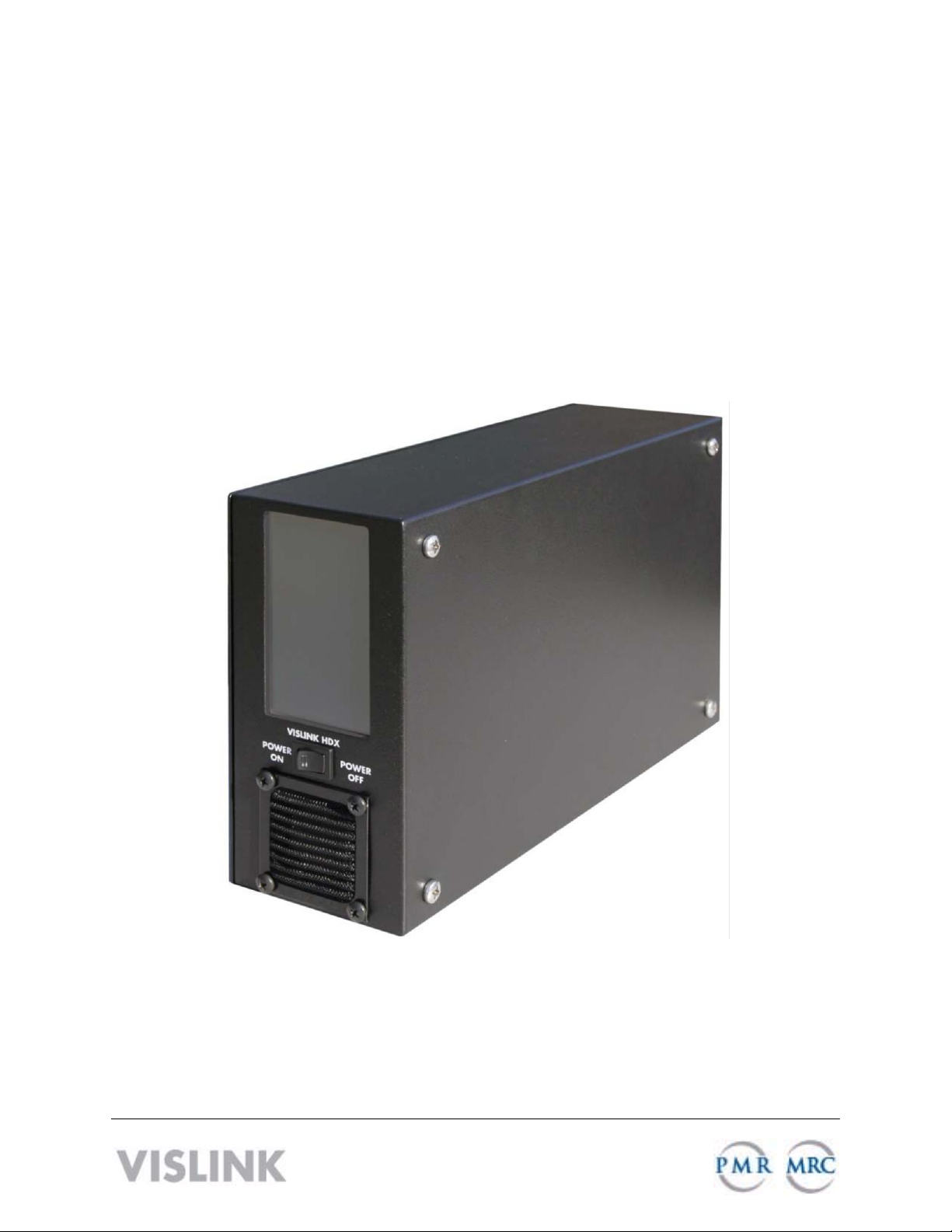
The HDX-1100 Aircraft/Terrestrial High Power HD
Video Transmitter (HDX-1100) (shown) is a
lightweight and rugged transmitter that is suited for
mobile and aircraft environments; able to withstand
constant vibration, shock, temperature swings, and
humidity. Common uses include law enforcement
surveillance and video collection.
The HDX-1100 supports H.264/MPEG-2 and
HD/SD. The HDX-1100 can transmit DVB-T
COFDM digital transmission (QPSK, 16QAM,
64QAM) consisting of a standard definition
(SD) NTSC or PAL video signals or highdefinition (HD) video signal (up to 1080i), plus
two audio signals and an RS-232 data
channel. The transmitter uses the MPEG-2
video compression format for high-quality
imagery.
The amplifier operates at 8W for all bands except 4940-4990 MHz which is limited to 1.0W
maximum. Low power mode is typically 3 to 6 dB below the maximum rating.
You can control the HDX-1100 with the touch screen user interface (see Section 3), or an
optional remote control unit (RCU) (see Section 4). You also can configure the HDX-1100 with a
PC using a web browser (see Section 5).
2 Operating in Safety
Guidelines for safe operation are derived from OET bulletin 65, August 1997, as recommended
by the Federal Communications Commission (FCC).
WARNING
The HDX-1100, operated without an antenna, will not create RF energy exceeding 1.0 mW/cm2,
the FCC limit for exposure. Connecting an antenna to the unit greatly enhances the potential for
harmful exposure, and you must maintain a certain distance from the radiator. The following
table shows the Maximum Permissible Exposure (MPE) safe distances from the antenna.
High levels of RF power are present in the unit. Exposure to RF or
microwave power can cause burns and may be harmful to he alth.
Remove power from the unit before disconnecting any RF cables and
before inspecting damaged cables and/or antennas. Avoid standing in
front of high gain antennas (such as a dish antenna) and never look into
the open end of a waveguide or cable where RF power may be present.
HDX-1100 User and Technical Manual 1

Note
Hazardous RF radiation limits and recommended distances may vary by
country. Observe all applicable state and federal regulations when using this
transmitter.
To perform calculations to understand the safe exposure margin (MPE), use the following
formula suggested by OET 65. The calculations provided are for common antennas often
utilized in the ENG environment.
Calculating MPE
EIRP = P * (10 ^ (G / 10)) = (antilog of G/10) * P
P = RF power delivered to the antenna in mW
G = Power gain of the antenna in the direction of interest relative to an isotropic radiator
R = distance to the center of radiation of the antenna in centimeters
S = MPE in mW/cm² (milliwatts per square centimeters)
Conversions
dBi to numeric gain = Antilog (dBi/10)
Feet to centimeters = Feet * 30.48
Centimeters to Feet = cm * .0328
4 π = 12.57
User Input
RF power delivered to the antenna = Watts
Antenna gain (referenced to isotropic antenna) = dBi
Distance from the center of radiation = Feet
Calculation steps:
1. [P] RF power input. Watts to milliwatts = Watts * 1000
2. [G] Antenna gain dBi. Numeric gain = Antilog (dBi/10)
3. [EIRP] Multiply P * G
4. [R] Centimeters to feet = Centimeters * .0328
5. Square R
6. Multiply R² * 4π
7. [S] Divide (R² * 4π) into EIRP
S = Power Density in milliwatts per square centimeters.
Note
At frequencies above 1500 MHz, S must not be greater than 1.
Reference
FCC OET Bulletin 65, August 1997 - Evaluating Compliance with FCC Guidelines for Human
Exposure to Radio Frequency Electromagnetic Fields
2 HDX-1100 User and Technical Manual
Power Dens
i
ty (mW
/
cm^2)
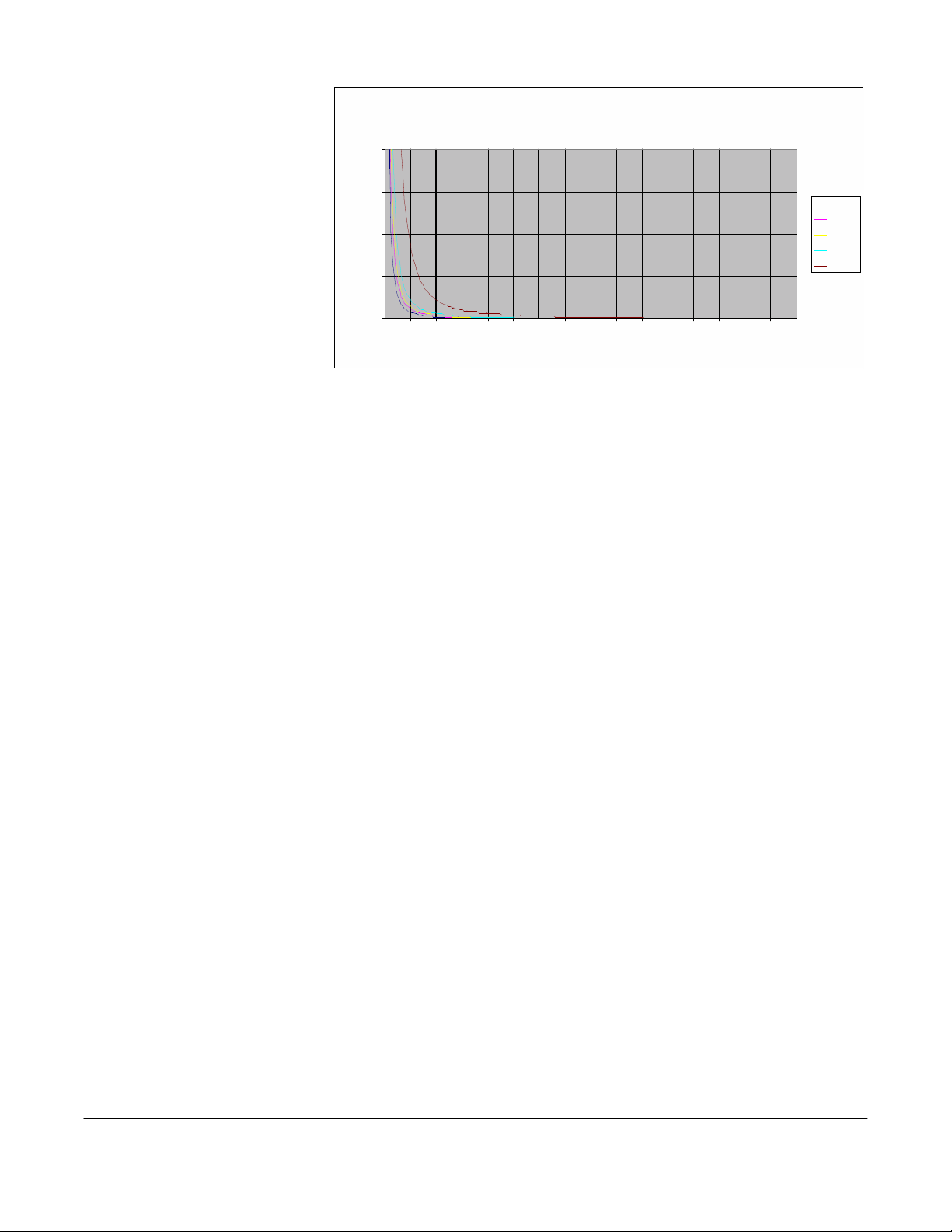
The figure to the right is a
typical graph for a Vislink
HDX-1100 Transmitter and
shows the permissible
exposure distance for
various antennas. Graphs
and data will vary, based on
the actual transmitter, output
power, frequency, and
antenna utilized. One plot
provides the permissible
output of the transmitter for
digital modulation, and the
other plot for analog
modulation.
2
1.5
1
0.5
0
0 0.5 1 1.5 2 2.5 3 3.5 4 4 .5 5 5.5 6 6.5 7 7.5
Maximum Permissible Exposure
@ 200 milliWatts RF Power
8
Distance in Feet
0dBi
2dBi
3dBi
5dBi
11dBi
Vislink, in accordance with the requirements set forth by the FCC, provides this information as a
guide to the user and assumes the users of this equipment are licensed and qualified to operate
the equipment per the guidelines and recommendations contained within the product user
guides and in accordance with any FCC rules that may apply.
3 Setting the HDX-1100 With the Touch Panel
The touch panel screen on the front of the unit lets you control the HDX-1100 directly as
described in the following sections.
3.1 Selecting a Preset
The HDX-1000 recalls the most recently saved preset when it is powered up. You can select
from up to 16 factory or custom preset configurations.To select a preset, do the following:
1. Press the PRESET key.
2. Press the up and down arrows to choose the new preset you want.
3. Press the SAVE key. If the SAVE key is not pressed within 5 seconds, the preset returns
to the most recently used value and the selection mode is canceled.
3.2 Selecting the Audio Input Level
The HDX-1100 recalls the most recently saved audio input level setting when it is powered up.
To select the input level for Audio 1 and Audio 2 between microphone or line level, do the
following:
1. Press the AUDIO 1 MIC/LINE or AUDIO 2 MIC/LINE key.
2. Press AUDIO 1 MIC/LINE or AUDIO 2 MIC/LINE key to toggle between MIC or LINE
level.
3. Press the SAVE key.If the SAVE key is not pressed within 5 seconds, the audio level
returns to the most recently used value and the selection mode is canceled.
HDX-1100 User and Technical Manual 3
 Loading...