

Microwave Radio Communications CR2TX2AD User Manual
Manual Part No. 400437-1
Rev. N March 2004
Applies to firmware Rev. 4.03
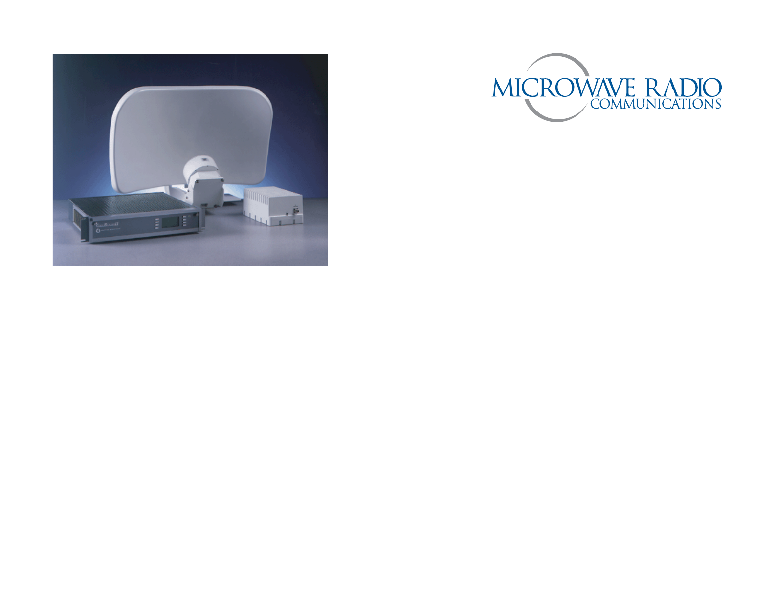
CodeRunner 2
Analog+Digital
Portable
MicrowaveTransmitter
Operator’s Guide


Notices
About This Manual
Part number 400437-1
Revision N
March 2004
The information in the manual applies to the MRC CodeRunner 2
Transmitter, firmware revision 4.03.
Proprietary Material
The information and design contained within this manual was
originated by and is the property of Microwave Radio
Communications. Microwave Radio Communications reserves
all patent proprietary design, manufacturing, reproduction use,
and sales rights thereto, and to any articles disclosed therein,
except to the extent rights are expressly granted to others. The
foregoing does not apply to vendor proprietary parts.
To allow for the introduction of design improvements,
specifications are subject to change without notice.
Copyright
The information in this book may be reproduced by the
purchaser to the extent needed for their organization. No part of
this material may be modified in any way or published for resale
without the express written authorization of Microwave Radio
Communications.
© 2004 Microwave Radio Communications
Microwave Radio Communications
101 Billerica Avenue - Bldg. 6
North Billerica, MA 01862-1256USA
TEL: 978.671.5700
FAX: 978.671.5800
Printed in U.S.A.
Regulatory Status
This product is certified to conform to CENELEC standards EN
55020, EN 55013, EN 50082-1 and EN 60950 and carries the
CE mark.
Authorized EU representative: Vislink PLC.
Microwave Radio Communications is ISO 9001 certified.
Notices iCodeRunner 2 Operator’s Guide

RF Exposure Warning
Conventions
The CodeRunner 2 is a radio transmitter. It is designed to
permit, produce and emit RF radiation into an antenna for the
purpose of delivering a digital or FM modulated signal to an
appropriate receiving device.
For equipment such as the CodeRunner 2, the Maximum
Permissible Exposure (MPE) limit is 1.0 mW/cm2. The
CodeRunner 2 is a low-powered device, and by itself will
generally not create RF exposure in excess of the MPE limits for
RF radiation (OET Bulletin 65, Addition 97-01) issued by the U.S.
Federal Communications Commission (FCC). However, when
properly connected to an antenna, the radiated power can
exceed the MPE limits.
The purchaser and/or user of the CodeRunner 2 is solely and
exclusively responsible for determining the level of RF exposure
when connecting the CodeRunner 2 to an antenna or other
equipment, taking all appropriate steps to limit RF exposure and
for ensuring compliance with all FCC requirements set forth in
OET Bulletin 65.
Pay special attention to information marked in one of the
following ways:
CAUTION
WARNING
Note
Notes provide additional information to assist you
in using and maintaining the equipment.
Follow CAUTIONS closely to prevent
personal injury or death.
Follow WARNINGS to prevent damage to
the equipment.
On-Line Viewing
Text displayed as blue contains a hypertext link. Click on the
hypertext to jump to that destination. Click on the
blue destination to return.
Viewing this manual on-line
requires Adobe Acrobat,
version 4.0 or above.
Click on this icon to download your
FREE copy of Adobe Acrobat
Reader.
Notices-iiCodeRunner 2 Operator’s Guide
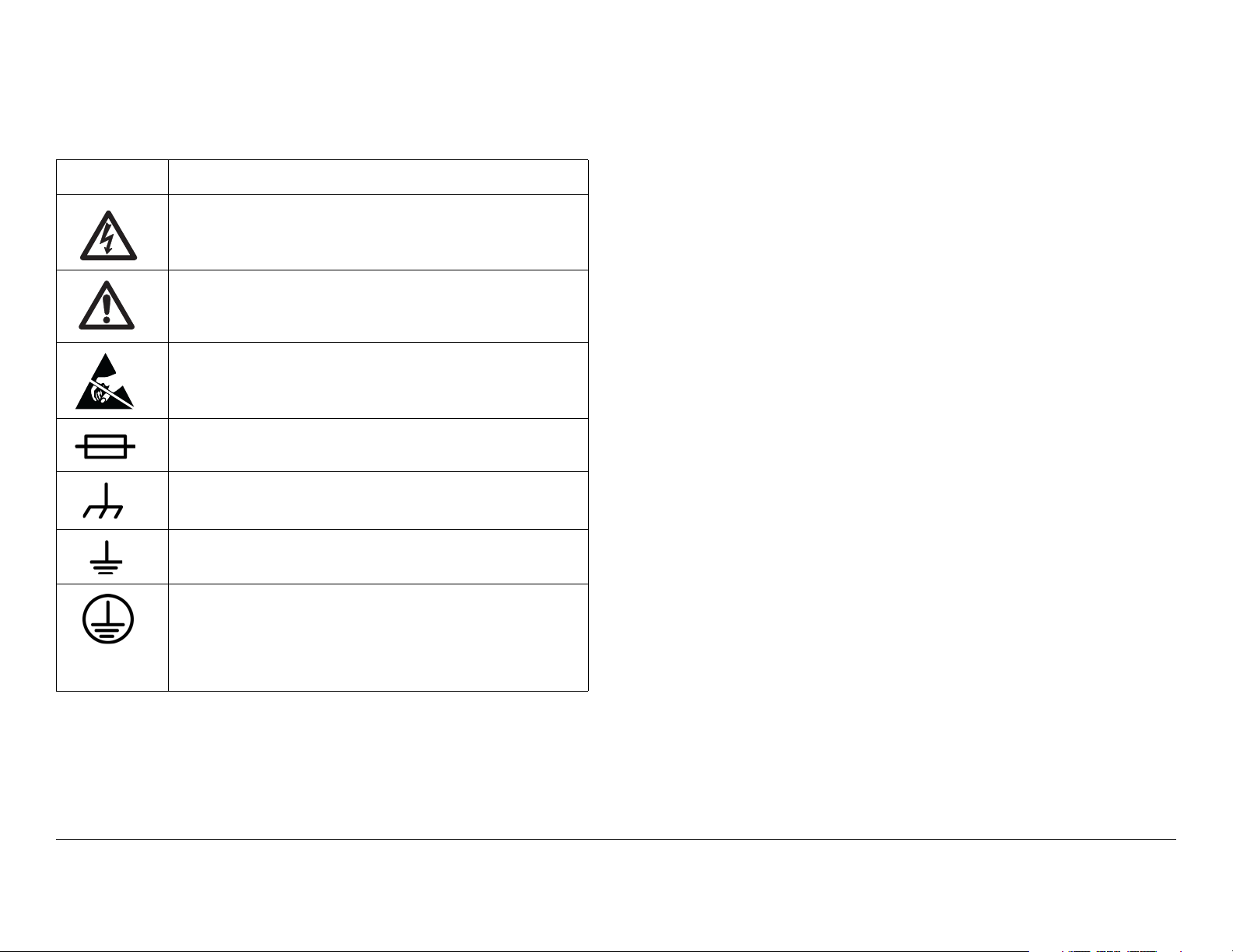
Symbols Used
Warranty Information
The following symbols are used on the equipment:
Symbol Meaning
CAUTION: Risk of Electric Shock
WARNING: General Warning. Risk of Danger
WARNING: Electrostatic Discharge. Possible
Damage to Equipment
Fuse - Identifies fuses or their location.
Frame or Chassis Ground - Identifies the frame or
chassis terminal.
Earth Ground - Identifies the earth Ground Terminal
Protective Earth Ground - Identifies any terminal
which is intended for connection to an external
conductor for protection against electric shock in
case of a fault, or the terminal on a protective earth
electrode.
Product Manufactured by MRC:
a. Products manufactured by MRC are warranted against
defects in material and workmanship for a period of two (2) years
from date of delivery as evidenced by MRC's packing slip or
other transportation receipt (unless otherwise noted).
b.MRC's sole responsibility under this warranty will be to either
repair or replace, at its option, any component which fails during
the applicable warranty period because of a defect in material or
workmanship, provided Buyer has promptly reported same to
MRC in writing. All replaced products and parts will become
MRC's property.
c.MRC will honor the warranty at the repair facility designated
by MRC. It is Buyer's responsibility to return, at its expense, the
allegedly defective product to MRC. Buyer must obtain a Return
Material Authorization (RMA) number and shipping instructions
from MRC prior to returning any product under warranty.
Transportation charges for the return of the product to Buyer will
be paid by MRC within the United States. For all other locations,
the warranty excludes all costs of shipping, customs clearance
and other related charges. If MRC determines that the product is
not defective within the terms of this warranty, Buyer will pay
MRC all costs of handling, transportation and repairs at the then
prevailing repair rates.
d.All the above warranties are contingent upon proper use of
the product. These warranties will not apply (i) if adjustment,
repair, or product or parts replacement is required because of
accident, unusual physical, electrical or electromagnetic stress,
neglect, misuse, failure of electric power, environmental controls,
transportation, failure to maintained properly or otherwise in
accordance with MRC specifications, or abuses other than
Notices-iiiCodeRunner 2 Operator’s Guide

ordinary use; (ii) if the product has been modified by Buyer or
has been repaired or altered outside MRC's repair facility, unless
MRC specifically authorizes such repairs or alterations in each
instance; or (iii) where MRC serial numbers, warranty data or
quality assurance decals have been removed or altered.
e.No person, including any dealer, agent or representative of
MRC is authorized to assume for MRC any other liability on its
behalf except as set forth herein. If any payment is due MRC for
services performed hereunder, it will be subject to the same
payment terms as the original purchase.
Products Manufactured By Others:
For products not manufactured by MRC, the original
manufacturer's or licensor's warranty will be assigned to Buyer to
the extent permitted by the manufacturer or licensor and is in lieu
of any other warranty, expressed or implied. For warranty
information on a specific product, a written request should be
made to MRC.
All Products:
materials used in connection with Buyer's order are for the sole
purpose of identifying the equipment and will not be construed as
an express warranty. Any suggestions by MRC or its agents
regarding use, application or suitability of the equipment will not
be construed as an express warranty. No warranties may be
implied from any course of dealing or usage of trade. Buyer
agrees that the exclusion of all warranties, other than those
expressly provided herein, is reasonable.
THE FOREGOING WARRANTIES AND REMEDIES ARE
EXCLUSIVE AND ARE IN LIEU OF ALL OTHER EXPRESS OR
IMPLIED WARRANTIES, OBLIGATIONS, AND LIABILITIES ON
THE PART OF MRC. EXCEPT FOR THE EXPRESS
WARRANTIES STATED HEREIN, MRC DISCLAIMS ALL
WARRANTIES ON PRODUCTS FURNISHED HEREUNDER,
INCLUDING, WITHOUT LIMITATION, ALL IMPLIED
WARRANTIES OF MERCHANTABILITY AND FITNESS FOR A
PARTICULAR PURPOSE. MRC WILL HAVE NO
RESPONSIBILITY FOR ANY PARTICULAR APPLICATION
MADE OF ANY EQUIPMENT. Any description of equipment,
whether in writing or made orally by MRC or its agents,
specification sheets, models, bulletins, drawings, or similar
Notices-ivCodeRunner 2 Operator’s Guide

Contents
Notices - - - - - - - - - - - - - - - - - - - - - - - - - - - - - - i
About This Manual - - - - - - - - - - - - - - - - - - - - - - - - i
Copyright - - - - - - - - - - - - - - - - - - - - - - - - - - - - - - - i
Proprietary Material - - - - - - - - - - - - - - - - - - - - - - - i
Regulatory Status - - - - - - - - - - - - - - - - - - - - - - - - - i
RF Exposure Warning - - - - - - - - - - - - - - - - - - - - - - - - ii
Conventions - - - - - - - - - - - - - - - - - - - - - - - - - - - - - - - ii
On-Line Viewing - - - - - - - - - - - - - - - - - - - - - - - - - - ii
Symbols Used- - - - - - - - - - - - - - - - - - - - - - - - - - - - - - iii
Warranty Information - - - - - - - - - - - - - - - - - - - - - - - - - iii
Product Manufactured by MRC: - - - - - - - - - - - - - - - iii
Products Manufactured By Others:- - - - - - - - - - - - iv
All Products: - - - - - - - - - - - - - - - - - - - - - - - - - - - iv
Contents - - - - - - - - - - - - - - - - - - - - - - - - - - - - - i
Introduction - - - - - - - - - - - - - - - - - - - - - - - - - 1-1
Chapter Overview - - - - - - - - - - - - - - - - - - - - - - - - - 1-1
What This Manual Covers - - - - - - - - - - - - - - - - - - - 1-1
How It’s Organized - - - - - - - - - - - - - - - - - - - - - - - - 1-1
Who It’s Written For - - - - - - - - - - - - - - - - - - - - - - - - 1-2
Related Documents - - - - - - - - - - - - - - - - - - - - - - - - 1-2
Ordering documentation- - - - - - - - - - - - - - - - - - - - - 1-2
Calling for Service - - - - - - - - - - - - - - - - - - - - - - - - - 1-2
Product Description- - - - - - - - - - - - - - - - - - - 2-1
Chapter Overview - - - - - - - - - - - - - - - - - - - - - - - - - 2-1
System Description - - - - - - - - - - - - - - - - - - - - - - - - 2-1
System Components - - - - - - - - - - - - - - - - - - - - - - - 2-3
Operating Controls - - - - - - - - - - - - - - - - - - - - - - - - 2-4
External Connectors - - - - - - - - - - - - - - - - - - - - - - - 2-5
IDU/ODU (RFU) Interconnection - - - - - - - - - - - - - - - 2-7
System Configurations - - - - - - - - - - - - - - - - - - - - - - 2-8
Single Band/Dual Antenna Configuration - - - - - - 2-8
Dual Band Non-Simultaneous Transmitting - - - - - 2-9
Dual Band Simultaneous Transmitting- - - - - - - - 2-10
For More Information - - - - - - - - - - - - - - - - - - - - - - 2-11
Routine Operation - - - - - - - - - - - - - - - - - - - - 3-1
Chapter Overview - - - - - - - - - - - - - - - - - - - - - - - - - 3-1
Overview of Controls - - - - - - - - - - - - - - - - - - - - - - - 3-1
Function Buttons - - - - - - - - - - - - - - - - - - - - - - - - - - 3-1
Polarization Select- - - - - - - - - - - - - - - - - - - - - - - 3-2
Band Select - - - - - - - - - - - - - - - - - - - - - - - - - - - 3-2
Antenna Select - - - - - - - - - - - - - - - - - - - - - - - - - 3-2
Status LEDs - - - - - - - - - - - - - - - - - - - - - - - - - - - - - 3-3
Display and Keypad - - - - - - - - - - - - - - - - - - - - - - - - 3-5
Display Layout - - - - - - - - - - - - - - - - - - - - - - - - - 3-5
Navigating using the display and keypad - - - - - - - 3-5
Frequently Performed Tasks - - - - - - - - - - - - - - - - - - 3-7
Turning the power ON and OFF - - - - - - - - - - - - - 3-7
Activating and deactivating the transmitter - - - - - 3-7
Switching between HI and LOW power - - - - - - - - 3-7
Selecting Channel and Offset - - - - - - - - - - - - - - 3-8
Switching between antennas - - - - - - - - - - - - - - - 3-8
Switching antenna polarization - - - - - - - - - - - - - 3-8
Switching bands - - - - - - - - - - - - - - - - - - - - - - - - 3-8
Switching between Analog and Digital modes - - - 3-8
Setting for Remote operation - - - - - - - - - - - - - - 3-9
Menu Maps - - - - - - - - - - - - - - - - - - - - - - - - - - - - - 3-10
Notes - Menu Maps - - - - - - - - - - - - - - - - - - - - - - 13
Channels & Frequencies - - - - - - - - - - - - - - - A-1
Appendix Overview - - - - - - - - - - - - - - - - - - - - - - - - A-1
Initial Factory Presets - - - - - - - - - - - - - - - - - - - - - - - A-1
US 12 MHz Channel Plan - - - - - - - - - - - - - - - - - - - - A-6
Glossary - - - - - - - - - - - - - - - - - - - - - - - - - - - B-1
Index - - - - - - - - - - - - - - - - - - - - - - - - - - - - - - - - i
Contents iCodeRunner 2 Operator’s Guide

Contents-iiCodeRunner 2 Operator’s Guide

1
Introduction
Chapter
Operator’s
Guide
Technical
Reference
Manual
1.1 Chapter Overview
This chapter will introduce you to the Operator’s Guide: what it
covers, how it’s organized, and who it’s written for.
1.2 What This Manual Covers
This manual describes how to operate the MRC CodeRunner 2
Transmitter.
For information on Installation, Repair, and Theory of Operation,
refer to the MRCCodeRunner2TechnicalReferenceManual.
1.3 How It’s Organized
The manuals for the CodeRunner 2 are organized as follows:
Technical
Reference
Manual
Chapter
Introduction
Operator’s
Guide
Installation
Troubleshooting
Repair
Replacement Parts
Theory of Operation
Appendix A - Channels
& Frequencies
Appendix B - Glossary
Appendix C - Module
Reference
Appendix D - Color Bar
Generator
Appendix E - Installing
Triax Connectors
Appendix F - Menu
Reference
Product Description
Routine Operation
Advanced Operation
Note
Introduction 1-1CodeRunner 2 Operator’s Guide
The Technical Reference Manual contains
everything in the Operator’s Guide, plus
additional technical content.

1.4 Who It’s Written For
This manual is intended for use by personnel assigned to
operate the CodeRunner 2. Users of this manual should already
be familiar with basic concepts of radio, video and audio.
1.5 Related Documents
• MRC CodeRunner 2 Quick Reference Guide (part no.
400453)
• MRC CodeRunner 2 Technical Reference Manual (part
no. 400465)
• MRC CodeRunner 2 Helicopter Remote Control (part no.
400461)
1.6 Ordering documentation
Any of the above manuals may be ordered by contacting MRC
Customer Service:
Business Hours: Monday - Friday
8:00 AM - 7:00PM Eastern Time (US)
(0800 - 1900 hrs US ET)
Telephone: 800-490-5700
978-671-5700
Fax: 978-671-5800
When contacting Customer Service, please have the following
information available:
- label on the rear panel
- label inside the front panel.
• Approximate purchase date.
• Firmware revision, found in two places:
- displays on screen at startup
- label inside the front panel.
1.7 Calling for Service
MRC Technical Support is available 24 hours a day, 7 days a
week. During regular business hours you can reach our expert
staff directly. After hours, your call will be forwarded to the on-call
technical support specialist.
Business Hours: Monday
8:00 AM - 5:00PM Eastern Time (US)
(0800 - 1700 hrs US ET)
Tuesday - Friday
8:00 AM - 7:00PM Eastern Time (US)
(0800 - 1900 hrs US ET)
Telephone: 800-490-5700
978-671-5700
Fax: 978-671-5800
Email: support@mrcbroadcast.com
• Model number and serial number of the unit. This is
located in two places:
When contacting Technical Support, please have the following
Introduction 1-2CodeRunner 2 Operator’s Guide

information available:
• Model number and serial number of the unit. This is
located in two places:
- on a label on the rear panel
- on a label inside the front panel.
• Approximate purchase date.
• Firmware revision, found in two places:
- displays on screen at startup
- on a label inside the front panel.
Introduction 1-3CodeRunner 2 Operator’s Guide

This page intentionally left blank.
Introduction 1-4CodeRunner 2 Operator’s Guide

2
ProductDescription
2.1 Chapter Overview
This chapter provides a overall description of the product, its
components, and its capabilities.
Here are the topics covered:
Topic Page
2.2 System Description
The MRC CodeRunner 2 transmitter is designed to be both an
analog and digital transmitter for ENG portable applications.
CodeRunner 2 can accommodate a variety of analog and digital
inputs, and apply either analog or digital modulation.
CodeRunner 2 is an integrated, flexible solution consisting of:
• A rack mounted Indoor Unit (IDU), typically mounted
inside an ENG vehicle.
• A mast mounted Outdoor Unit (ODU), also called the RF
Unit (RFU).
System Description 2-1
System Components 2-3
Operating Controls 2-4
External Connectors 2-5
IDU/ODU (RFU)
Interconnection
System Configurations 2-8
Single Band/Dual
Antenna Configuration
Dual Band NonSimultaneous
Transmitting
Dual Band Simultaneous
Transmitting
For More Information 2-11
2-7
2-8
2-9
2-10
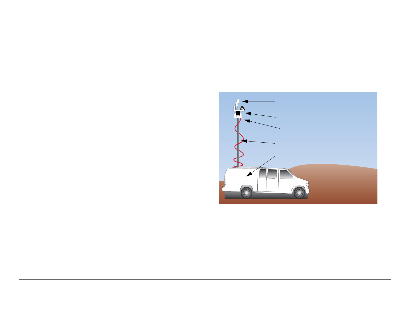
A typical installation is shown in Figure 2-1.
PowerOptionsThe CodeRunner 2 can be operated from
115 V / 220 V AC mains power, or from 18-36 V DC vehicle
power. Power is supplied to the IDU, which in turn powers the
ODU via the cable harness between them.
Analog/DigitalOptionsThe CodeRunner 2 is digital-ready,
which means it can be ordered and installed as a full-featured
analog radio. Then later, it can be upgraded just by adding the
digital MPEG/COFDM Module.
Band&FrequencyOptionsThe CodeRunner 2 is designed to
cover the bands below. It can be ordered as a single-band unit or
in a dual-band configuration to cover any two of these bands.
• 2-3 GHz
• 6-7 GHz
• 12-13 GHz
Band and frequency information is stored in the ODU, which
means switching bands after installation is very simple: just plug
in the RFU for the new band, and the IDU will automatically
configure itself for the new band.
Product Description 2-1CodeRunner 2 Operator’s Guide/Tech Ref Manual
Within these bands, channels can be preprogrammed at the
factory to match either the US broadcast channel plan, or a plan
specified by the customer. Channel frequencies can be
reprogrammed in the field using the keypad and display on the
IDU.
• MRC Ellipse 2000
• MRC OmniPole Omnidirectional
Switching functions for band and antenna polarization are
controlled from the front panel of the IDU.
ColorBarGeneratorOptionsFor analog operation, an
optional analog color bar generator is available, either at time of
purchase or for later upgrade in the field. The digital MPEG/
COFDM Module has a built-in digital color bar generator. Either
the analog or digital generators are field configurable for
functions such as auto-standby (mute the transmitter on loss of
video) and auto-generate (provide tones and bars on loss of
video).
ConnectionOptionsThe CodeRunner 2 is designed to make
upgrading from an older radio as painless as possible. The IDU
and ODU can be ordered with a variety of connectors to plug into
an existing wiring harness. The connectors available for the
cable harness between the IDU and ODU are:
•Triax
• Type ‘N’
•TNC
The ODU comes with a standard Type N connector for the
antenna connection.
If your installation involves more than one antenna, this can be
easily accommodated by using the MRC RF Switch. The RF
Switch is also controlled from the front panel of the IDU.
Figure 2-1: Typical CodeRunner 2 System
Antenna
Pan & Tilt Assembly
Outdoor Unit (ODU)
Conduit (Nycoil)
Indoor Unit (IDU)
(inside vehicle)
AntennaOptionsThe CodeRunner 2 is fully compatible with a
variety of antennas, including:
• MRC ProStar, models
- 2A20 and 2A20SS (2 GHz)
- 7A30 and 7A30SS (7 GHz)
- 2A20/7A30 (dual band 2 & 7 GHz)
- 2A20/7A30SS (dual band 2 & 7 GHz, solid state
switching)
Product Description 2-2CodeRunner 2 Operator’s Guide/Tech Ref Manual
2.3 System Components
An MRC CodeRunner 2 system is made up of the following
components:
• A rack mounted Indoor Unit (IDU), typically mounted
inside an ENG vehicle.
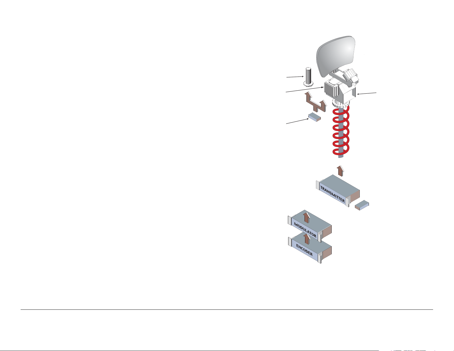
Figure 2-2: CodeRunner 2 System Components
Directional Antenna
(MRC 2A20, 7A30, Ellipse 2000)
• A mast mounted Outdoor Unit (ODU), also called the RF
Unit (RFU).
A typical system is shown in Figure 2-2.
The IDU contains the baseband circuitry, power supply, and
control modules. It accepts a variety of audio and video inputs,
both digital and analog, and generates a 70 MHz IF output. It
also accepts IF input from external modulators.
For digital operation, the IDU can be equipped with an optional
internal MPEG/COFDM Module. Or, the IDU can be used with
existing external digital encoders and modulators.
The ODU contains the upconvertors and power amplifier. The
ODU accepts the 70 MHz IF, converts it to the operating band
chosen, and amplifies it.
Every installation will include an antenna, either directional or
omnidirectional, or both. An MRC RF Switch can be mounted up
on the mast to select the antenna desired.
When using a mast mounted antenna, a Nycoil conduit sheath
covers the wiring harness between the IDU to the ODU. This
harness carries the power, IF, and antenna band and polarization
switching. Addition wiring is added for controlling the pan & tilt
mechanism, and for implementing additional functions such as
off-air monitors, mast lights, etc.
OmniPole Antenna
Outdoor RF Unit
(Upconvertor,
Power Amp)
RF Switch
External
Modulator
(Optional)
External
Encoder
(Optional)
Pan & Tilt Assembly
Conduit (Nycoil)
CodeRunner 2 Indoor Unit
(Baseband, Audio/Video Modules)
Internal
MPEG Encoder &
COFDM Modulator
(Optional)
Product Description 2-3CodeRunner 2 Operator’s Guide/Tech Ref Manual
 Loading...