

CodeRunner 4
Table of Contents
Section 1 - System Overview
Section 2 - System Installation
Section 3 - Operating Controls
Section 4 - Troubleshooting
Analog & Digital
Central Receiver
Section 5 - Remote Operation
Section 6 - Media Switch
Appendix A - Receiver Interconnections
Appendix B - Frequencies
Appendix C - Modules
Appendix D - Antenna Configurations
Document: 400438-1
Revision J September 2007
Operator’s Guide

PROPRIETARY NOTICE
The information and design contained within this manual was originated by and is the property of
Microwave Radio Communications (MRC). Microwave Radio Communications reserves all
patent proprietary design, manufacturing, reproduction use, and sales rights thereto, and to any
articles disclosed therein, except to the extent rights are expressly granted to others. The
foregoing does not apply to vendor proprietary parts.
To allow for the introduction of design improvements, specifications are subject to change
without notice.
©2007 Microwave Radio Communications
Printed in the U.S.A.
September 2007
Revision Date
A February 2000
B March 2000
C July 2000
D January 2001
E July 2001
F July 2002 ECO 2137
G October 2002 ECO 2195
H October 2002 ECO 2222
J September 2007
Microwave Radio Communications
101 Billerica Avenue – Bldg 6
North Billerica, MA 01862-1256
USA
TEL: 800.490.5700
978.671.5700
FAX: 978.671.5800
Safety Precautions
Warnings, Cautions, and Notes
Use the following table to interpret how to distinguish between Warnings, Cautions, and Notes
Warning
Caution
Note
Safety Symbols
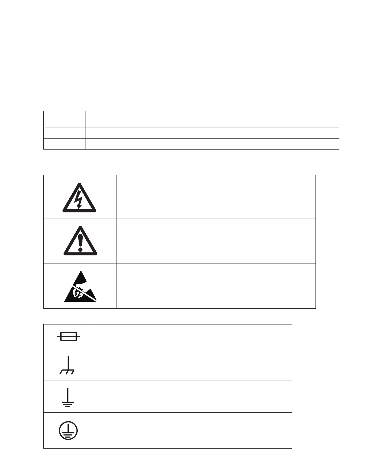
The following safety symbols are used in this manual:
Gives information which, if strictly observed, will prevent personal injury or death, damage to personal
property, or the environment.
Gives information which, if strictly followed, will prevent damage to equipment or other goods.
Provides supplementary information.
WARNING:
Risk of Electric Shock
WARNING:
General Warning
Risk of Danger
CAUTION:
Electrostatic Discharge.
.
Possible Damage to Equipment
Nomenclature and Markings
Fuse - Identifies fuse boxes or their locations.
Frame or Chassis Ground - Identifies the frame ground
terminal.
Earth Ground - Identifies the earth ground terminal.
Protective Earth Ground - Identifies any terminal which is
intended for connection to an external conductor for
protection against electric shock in case of a fault, or the
terminal of a protective earth ground electrode.
.

Important Safeguards
Warning:
1. Read all of these instructions.
2. Save these instructions for later use.
3. Follow all warnings and instructions
marked on the units.
Read Instructions - All safety and
operating instructions should be carefully
1
read before operating the equipment.
Retain Instructions - The safety and
operating instructions should be retained
2
and stored in a convenient place for future
reference.
Heed Warnings - All warnings on this
equipment, and in the operating instructions
3
should be strictly adhered to.
Follow Instructions - All operating and user
instructions should be properly
4
implemented for optimum and safe
performance.
Cleaning - Do not use liquid cleaners or
aerosol cleaners. Instead, use only a damp
5
cloth for cleaning.
Attachments - Do not use attachments not
authorized by Microwave Radio
6
Communications. Using unauthorized
attachments may create safety hazards or damage
the equipment.
Water and Moisture - Indoor equipment is
not designed to withstand water or moisture
7
beyond the limits noted in the product
specifications.
Accessories - Do not place equipment on
an unstable cart, stand, tripod, bracket, or
8
table. The product could fall, causing
serious personnel injury or damage the equipment.
Use only equipment recommended by Microwave
Radio Communications. When mounting or installing
the equipment, follow the manufacturer's
instructions.
Grounding or Polarization - AC powered
10
This plug fits into a standard, grounded power outlet.
If you are unable to insert the plug into the outlet,
contact your electrician to replace your obsolete
outlet. Do not defeat the safety purpose of the
grounded plug.
11
equipment items. Pay particular attention to cords at
plugs, convenience receptacles, and at the point
where they enter and exit the equipment.
12
can result in fire or electric shock.
13
following conditions occur:
1. If the power supply cord or plug has been
2. If liquid has been spilled in the equipment, or
3. If the equipment does not operate normally by
When the equipment exhibits a distinct change in
performance indicating the need for service.
14
Unauthorized substitutions could result in fire,
electric shock, or damage to the equipment.
versions of this product are equipped with a
3-wire plug with an integral grounding pin.
Power Cord Protection - Power supply
cords should be routed so that they are not
likely to be walked on or pinched by other
Object or Liquid Entry - Never spill liquids
or insert objects of any kind through
openings in the equipment. Such actions
Damage Requiring Service - Unplug the
radio product from the power outlet and
contact service personnel when the
damaged.
objects have fallen into the equipment.
following the operating instructions and
adjusting only those controls that are covered by
the operating instructions. Improperly adjusting
or tampering with controls not covered in the
operating instructions may result in damage to
the equipment or require extensive work by a
qualified technician to restore the radio to its
normal operation.
Replacement Parts - When replacing
parts is required, use only parts authorized
by Microwave Radio Communications.
Power Sources - The equipment should be
operated only from the type of power source
9
indicated on the unit, or in the operating
instructions. For 220 VAC operation, the proper
power cord must be used.
Safety Check - Upon completing any
15
determine that the equipment is in proper operating
condition.
service or repairs to the equipment, ensure
that safety checks are performed to

Table of Contents
1 System Overview .............................................................................................................1-1
Figure 1-1 CodeRunner 4 Block Diagram....................................................................... 1-2
Figure 1-2 Front Panel..................................................................................................... 1-3
Figure 1-3 Rear Panel Connections - Typical.................................................................. 1-3
2 System Installation ..........................................................................................................2-1
2.1 Unpacking and Handling ........................................................................................................2-1
2.1.1 Inspection ........................................................................................................................2-1
2.1.2 Damage in Shipment ....................................................................................................... 2-1
2.2 Installation Prerequisites ........................................................................................................2-2
Figure 2-1 Rack Clearances – Top View......................................................................... 2-2
2.2.1 Grounding the Equipment Rack ......................................................................................2-3
2.3 Rack Installation .....................................................................................................................2-4
Figure 2-2 Rack Installation ............................................................................................ 2-4
2.4 Equipment Rack Installation ..................................................................................................2-4
Table 2-1 Equipment Rack Specifications ..................................................................... 2-4
Figure 2-3 Equipment Rack Template............................................................................. 2-5
Figure 2-4 Equipment Rack – Front View ...................................................................... 2-6
2.5 Initial Power-up Procedure .....................................................................................................2-6
3 Operating Controls ..........................................................................................................3-1
3.1 Common Key Functions ......................................................................................................... 3-1
3.2 Receiver Screens ....................................................................................................................3-1
Figure 3-1 Receiver Screens............................................................................................ 3-1
3.2.1 Main Screen .....................................................................................................................3-2
Figure 3-2 Main Screen ................................................................................................... 3-2
3.2.2 Menu Screen .................................................................................................................... 3-3
Figure 3-3 Menu Screen ................................................................................................. 3-3
3.2.3 Remote Control Menu .....................................................................................................3-4
Figure 3-4 Remote Control Menu.................................................................................... 3-4
3.2.4 Configuration Screen .......................................................................................................3-5
Figure 3-5 Configuration Screen ..................................................................................... 3-5
3.2.5 Modify Channel Plan Screen ...........................................................................................3-5
Figure 3-6 Modify Channel Plan Screen ......................................................................... 3-5
3.2.6 RF Tray Screen ................................................................................................................3-6
Figure 3-7 RF Tray Screen .............................................................................................. 3-6
3.2.7 Power Supply Status Screen ............................................................................................ 3-7
Figure 3-8 Power Supply Status Screen .......................................................................... 3-7
3.2.8 Digital Demodulator Screen ............................................................................................3-8
Figure 3-9 Digital Demodulator Screen .......................................................................... 3-8
3.2.9 Video Demodulator Screen ............................................................................................. 3-9
Figure 3-10 Video Demodulator Screen.......................................................................... 3-9
3.2.10 Audio Screen .................................................................................................................3-10
Figure 3-11 Audio Screen.............................................................................................. 3-10
4 Troubleshooting ..............................................................................................................4-1
4.1 Front Panel Indicators .............................................................................................................4-1
CodeRunner 4 Operator’s Guide
400438-1 Rev. J
v

Figure 4-1 Front Panel LEDs........................................................................................... 4-1
4.2 System Alarms ........................................................................................................................4-2
Figure 4-2 Main Screen .................................................................................................. 4-2
Table 4-1 System Alarms ................................................................................................ 4-2
4.3 Replacing the Fuse .................................................................................................................4-3
Figure 4-3 CodeRunner 4 Rear Panel - Typical ............................................................. 4-3
5 Remote Operation ...........................................................................................................5-1
5.1 Local and Remote Operation ..................................................................................................5-1
5.2 Command Inputs to the Remote Connector ...........................................................................5-2
Table 5-1 Remote Interface Connections ........................................................................ 5-2
5.2.1 Control Functions ............................................................................................................5-3
Table 5-2 RF Channel Selection...................................................................................... 5-3
Table 5-3 Offset Selection, – Active High ...................................................................... 5-3
Table 5-4 Band Select – Active High .............................................................................. 5-3
Table 5-5 IF Bandwidth Select – Active High ................................................................ 5-3
Table 5-6 Squelch Control – Active High ....................................................................... 5-4
Table 5-7 Digital Mode Select/Active High.................................................................... 5-4
Table 5-8 Digital Mode Select/Active High.................................................................... 5-4
5.2.2 Vdc Bias Supply ..............................................................................................................5-4
5.2.2.1 Ground .....................................................................................................................5-4
5.2.3 Status Outputs – Remote Connector J7 ...........................................................................5-4
5.2.3.1 Receiver Signal Strength Indication - Analog .........................................................5-4
5.2.3.2 Remote Mode Status ................................................................................................ 5-4
5.2.3.3 Squelch Alarm ..........................................................................................................5-4
6 Media Switch ....................................................................................................................6-1
6.1 Overview ................................................................................................................................6-1
Figure 6-1 Media Switch Block Diagram........................................................................ 6-1
6.2 Mounting the Media Switch ...................................................................................................6-2
Figure 6-2 Media Switch on CR4 Rear Panel ................................................................. 6-2
6.3 Media Switch Connections .....................................................................................................6-2
Figure 6-3 Media Switch Connections ............................................................................ 6-2
6.4 System Interconnection ..........................................................................................................6-3
Figure 6-4 System Interconnection.................................................................................. 6-3
6.5 Harness Assemblies ................................................................................................................6-4
Figure 6-5 Power & IF Control Harness (907008).......................................................... 6-4
Figure 6-6 Audio Harness (906978) ................................................................................ 6-4
A Receiver Interconnections ............................................................................................A-1
A.1 Cabinet Connections .............................................................................................................. A-1
Figure A-1 CodeRunner Rear Panel Connectors - Typical ............................................ A-1
A.2 Remote Interface Connector ..................................................................................................A-2
Table A-1 Remote Interface Connections (J7) ............................................................... A-2
Table A-2 Serial Port (J8)............................................................................................... A-3
Table A-3 Summary Alarm (J3) ..................................................................................... A-3
Table A-4 Rx Status (J13) .............................................................................................. A-3
vi
CodeRunner 4 Operator’s Guide
400438-1 Rev. J

Figure A-2 Receiver Interconnection Diagram - RF Shelf............................................. A-4
Figure A-3 Receiver Interconnection Diagram - Backplane .......................................... A-5
B Frequencies ....................................................................................................................B-1
B.1 Channel Frequencies ............................................................................................................. B-1
Table B-1 2 GHz Channel Guide (17 MHz Channel Plan) ............................................ B-1
Table B-2 2 GHz Channel Guide (12 MHz BAS Channel Plan) ................................... B-2
Table B-3 7 GHz Channel Guide.................................................................................... B-2
Table B-4 13 GHz Channel Selection Guide.................................................................. B-3
C Modules .........................................................................................................................C-1
Figure C-1 Receiver Components - Top View ............................................................... C-1
C.1 Rx Video Demodulator .......................................................................................................... C-2
Figure C-2 Rx Video Demodulator Adjustments .......................................................... C-2
C.2 Audio SubCarrier Motherboard ............................................................................................. C-3
Figure C-3 Audio Subcarrier Motherboard ................................................................... C-3
D Antenna Configurations ................................................................................................D-1
D.1 Overview ............................................................................................................................... D-1
Figure D-1 Central Receive - Analog/Digital ................................................................ D-1
Figure D-2 Central Receive with Analog/Digital Media Switch.................................... D-2
CodeRunner 4 Operator’s Guide
400438-1 Rev. J
vii

This page intentionally left blank.
viii
CodeRunner 4 Operator’s Guide
400438-1 Rev. J

Preface
Purpose
This manual explains how to install, operate, and configure the MRC CodeRunner 4 Central Receiver.
Audience
This manual is intended for qualified installers and service technicians who need to perform the
following tasks:
• Install the receiver in a standard rack mount.
• Power up and configure the system for either analog or digital system configurations.
• Troubleshoot common system problems.
For commonly used abbreviations and acronyms, see the Glossary on page x.
Related Documents
• MAC-1000 Master Antenna Controller
• ASC-140 Slave Antenna Controller
• MRC 2000 Antenna Controller
• ProScan Antenna
• MicroScan Antenna
• UltraScan Antenna
• SectorScan Antenna
• Ellipse CR Antenna
• Sector CR Antenna
• Omnipole Antenna
Customer Service
Customer Service Hours: Monday through Thursday
8 AM to 7 PM, Eastern Time (US)
Friday
8 AM to 5 PM, Eastern Time (US)
Telephone: 800-490-5700 (Press 3)
978-671-5700 (Press 3)
Fax: 978-671-5948
Technical Support
Technical Support Service Hours: Monday through Friday
8 AM to 7 PM
Telephone: 800-490-5700 (Press 4)
978-671-5700 (Press 4)
Fax: 978-671-5948
After regular business hours and on weekends and holidays, you can also reach our expert staff as
follows:
Telephone: 978-671-5929
Your call will be automatically forwarded to the on-call Technical Support Specialist.
CodeRunner 4 Operator’s Guide 400438-1
Rev. J
ix

Preface
When contacting Customer Service or Technical Support, please have the following
information available:
• Model number and serial number of the unit.
• Approximate purchase date.
• Unit identification markings and revision.
• Be prepared to accurately describe the problem.
Glossary
This section describes commonly used acronyms and abbreviations used in
telecommunications and those specific to MRC Broadcast Products Group.
Term Definition
ØLK Phase Lock
3RU 3 Rack Unit height
A & C Alarm and Control
ADPCM Adaptive Differential Pulse Code Modulation
AFC Automatic Frequency Control
AGC Automatic Gain Control
AIS Alarm Indication Signal (all one’s)
AMI Alternate Mark Inversion, line code format for traffic data.
AVG Average
B8ZS Bipolar 8 Zero Substitution, line code format for traffic data.
BB Baseband
BER Bit Error Rate
BNC Bayonet lock coaxial connector
BPF Band Pass Filter
BPS Bits per second
CCITT International Telegraph and Telephone Consultative Committee, a
telecommunications standardizing committee of the ITU.
Composite A band or grouping of frequencies and/or subcarriers, including video,
occupied by the signal in a radio transmission system. Same as
baseband signal.
dB Decibel
dBm A unit of measurement referenced to one milliwatt.
DMUX,
DEMUX
Duplex A channel capable of transmitting information simultaneously in either
E1 2.048 Mbps traffic rate
EIA Electronic Industries Association, an industry association that
EMC Electromagnetic compatibility
Demultiplexer
direction
establishes various standards.
x
CodeRunner 4 Operator’s Guide 400438-1 Rev. J

Preface
Term Definition
EOW Engineering Order Wire
ERRS Errors
ESD Electrostatic discharge
FCC Federal Communications Commission, the United State's
communications regulatory agency.
FIFO First in, first out buffer
FIR Finite Impulse Response
FLR MRC's model designation for frequency modulated (FM) remodulating
radio systems from 2 to 15 GHz. FLR2 is the 2 GHz band version;
FLR4, the 4 GHz band version, etc.
FPGA Field Programmable Gate Array
GND Ground
H/W Hardware
HDB3 High Density Bipolar 3 line code format for traffic data
HPF High Pass Filter
I In phase
ID Identification
IF Intermediate Frequency
IRE 1. Institute of Radio Engineers, an international professional radio
engineering association that establishes various standards.
2. A unit of measurement, established by the IRE, in which 1 IRE Unit
=.00714 volts peak-to-peak (Vp-p) and 140 IRE units equals 1 Vp-p.
Kbps Kilobits per second
KHz Kilo (1,000) cycles per second
LCD Liquid Crystal Display
Lcl Local
LED Light emitting diode
LO Local Oscillator
LOS Loss of Signal
LPF Low Pass Filter
Mbps Megabits per second
MHz Million (1,000,000) cycles per second
MRC Microwave Radio Communications
MUX Multiplexer
NRZ Near Return to Zero
PER Parity Error Rate
PLL Phase Lock Loop
Q Quadature phase
QPSK Quadrature Phase Shift Keying
CodeRunner 4 Operator’s Guide 400438-1 Rev. J
xi

Preface
Term Definition
RCL Received Carrier Level
RSL Received Signal Level
Rcvr Receiver
RF Radio Frequency, any frequency of electromagnetic radiation or
alternating currents in the range from 3 kHz to 300 GHz; as in RF
Signal or RF Transmission.
RF Level RF Power from the transmitter
Rx Receiver
S/W Software
SC Service Channel
Setpt Set point
Simplex A channel capable of transmitting information in only one direction.
Site ID A physical location where any number of modems, transmitters, or
receivers are installed.
STDBY Standby
Subcarrier An electromagnetic signal that is used as a medium for placing an
information channel above another information channel.
SYNTH Synthesizer
T1 1.544 Mbps traffic rate
Tx Transmitter
VCO Voltage Controlled Oscillator
VCXO Voltage Controlled Crystal Oscillator
VDC Volts Direct Current
VF Voice Frequency
Video A term pertaining to the bandwidth and spectrum of the signal that
results from television scanning and which is used to reproduce a
picture.
Xmitr Transmitter
Xmtr Transmitter
xii
CodeRunner 4 Operator’s Guide 400438-1 Rev. J

Section
1 System Overview
This section provides an overview of the MRC CodeRunner 4 Central Receiver. For a
system block diagram of the receiver, see
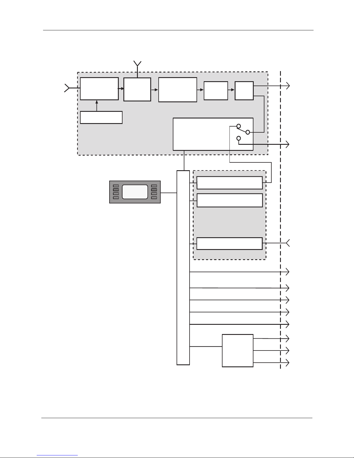
The CodeRunner 4 Central Receiver is capable of receiving in both analog or digital mode.
In the analog mode, the receiver outputs an NTSC signal with 4 audio channels, baseband,
and filtered video. In digital mode, the receiver outputs a digital data stream using either an
internal or external modem.
The incoming RF signal is down-converted to 70 MHz, filtered, and amplified. The output
from the IF Amplifier is split into two paths:
• A +5 dBm signal is routed to an analog demodulator, if one is installed.
• A second –10 dBm signal is routed to the power distribution board on the RF shelf.
Here the IF is switched to a direct rear panel connection. The switch is controlled
from the front panel display and keypad.
Power is brought to the receiver via a rear panel receptacle mounted on the plug-in power
supply. The power is routed through the rear panel backplane to the front panel display and
to the power distribution board on the RF tray,
All receiver functions are controlled from the front panel display and keypad. The receiver
can be controlled remotely and switched between analog or digital mode from either the
local or remote location.
The front panel displays common system faults with four LED indicators for power,
squelch, summary alarm, and remote/local status. Summary alarm messages appear as
scrolling text on the front panel LCD, A list of summary alarms and troubleshooting guide
can be found in
Section 4, Troubleshooting on page 4-1.
Figure 1-1 on page 1-2.
1
For remote cabling and interconnections, see Appendix A, Receiver Interconnections.
For more information on the operating controls, see Section 3, Operating Controls on
page 3-1.
The receiver mounts in a standard 3RU rack unit. See Section 2, System Installation on
page 2-1.
CodeRunner 4 Operator’s Guide
400438-1 Rev. J
1-1
System Overview
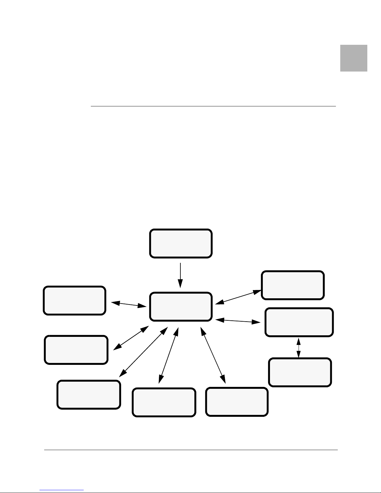
Figure 1-1 CodeRunner 4 Block Diagram
815 MHz OUT
RF
INPUT
LOW
NOISE
CONVERTER
SYNTHESIZER
RF SHELF
12 dB
COUPLER
LCD
DISPLAY
&
KEYPAD
2ND
DOWN
CONVERTER
DISTRIBUTION
IF
FILTER
POWER
BOARD
VIDEO DEMODULATOR
AUDIO DEMODULATOR
POWER SUPPLY
PLUG-IN MODULES
IF
AMP
EXTERNAL
MODEM
REAR PANEL
IF
OUTPUT
AC
INPUT
1-2
AUDIO
OUTPUT
(4 Chan.)
VIDEO
REAR PANEL BACKPLANE
REMOTE
I/0
BASEBAND
SUMMARY
ALARM
Rx STATUS
SERIAL
PORT
REMOTE
INTERFACE
PGM I/O
CodeRunner 4 Operator’s Guide 400438-1 Rev. J

Figure 1-2 Front Panel
System Overview
MRC CodeRunner 4
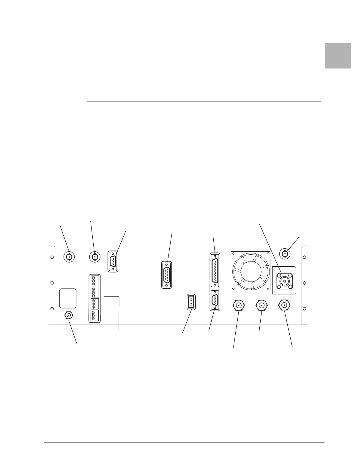
Figure 1-3 Rear Panel Connections - Typical
(J1)
(J12)
(J11)
(J15)
(J16)
SUM
ALARM
(J3)
VIDEO BB
(J2)
~AC POWER
120/240; .4A
50/60 HZ
FUSE:
T1A 250 VA C
"CAUTION
DOUBLE-FUSE
NEUTRAL/FUSING"
AUDIO
1
2
3
4
RX STATUS
(J13)
(J9)
PGM I/O
REMOTE
INTERF
SERIAL
PORT
ACE
POWER
REMOTE
SQUELCH
ALARM
DIGCR_FR
815 MHz OUT
RF IN
(J7)
(J8)
IF I/O
EXT MODEMDATA OUT
CodeRunner 4 Operator’s Guide 400438-1 Rev. J
1-3

System Overview
This page intentionally left blank.
1-4
CodeRunner 4 Operator’s Guide 400438-1 Rev. J

Section
2 System Installation
This section explains how to install the MRC CodeRunner 4, Digital Central Receiver. The
following topics are covered:
• Unpacking and Handling
• Installation Prerequisites
• Rack Installation
2.1 Unpacking and Handling
Each unit is shipped assembled, wired, and factory tested. Each unit is packaged in
appropriate shipping containers. Care should be taken when removing equipment from the
container to prevent damage to the unit. Check that all parts and accessories are removed
from the container and packing material before they are discarded. Verify that the
equipment items shipped agree with those listed on the sales order.
Note: DO NOT discard the container or any packing material until the
mechanical inspection has been satisfactorily completed. This
material must be available in the event that a damage claim needs to
be filed with the shipping carrier.
2
2.1.1 Inspection
Inspect the equipment for any shipping damage. Check that the equipment is clean and that
no cables or connectors are broken, damaged, or loose.
Note: At the time of inspection, DO NOT make any adjustments to internal
controls or adjustments. The equipment has been factory adjusted for
proper operation prior to shipment.
2.1.2 Damage in Shipment
Should any damage be discovered after unpacking the unit, use the following procedure:
1. Immediately file a claim with the shipping carrier.
2. Forward a copy of the damage report to MRC.
3. Contact Customer Service at which time they will determine the disposition of the
equipment.
For Customer Service information, see the Preface section of this manual.
CodeRunner 4 Operator’s Guide
400438-1 Rev. J
2-1
System Installation
Installation Prerequisites
2.2 Installation Prerequisites
Complying with installation prerequisites prevents problems from arising during
installation or future maintenance of the unit. Use the following guidelines:
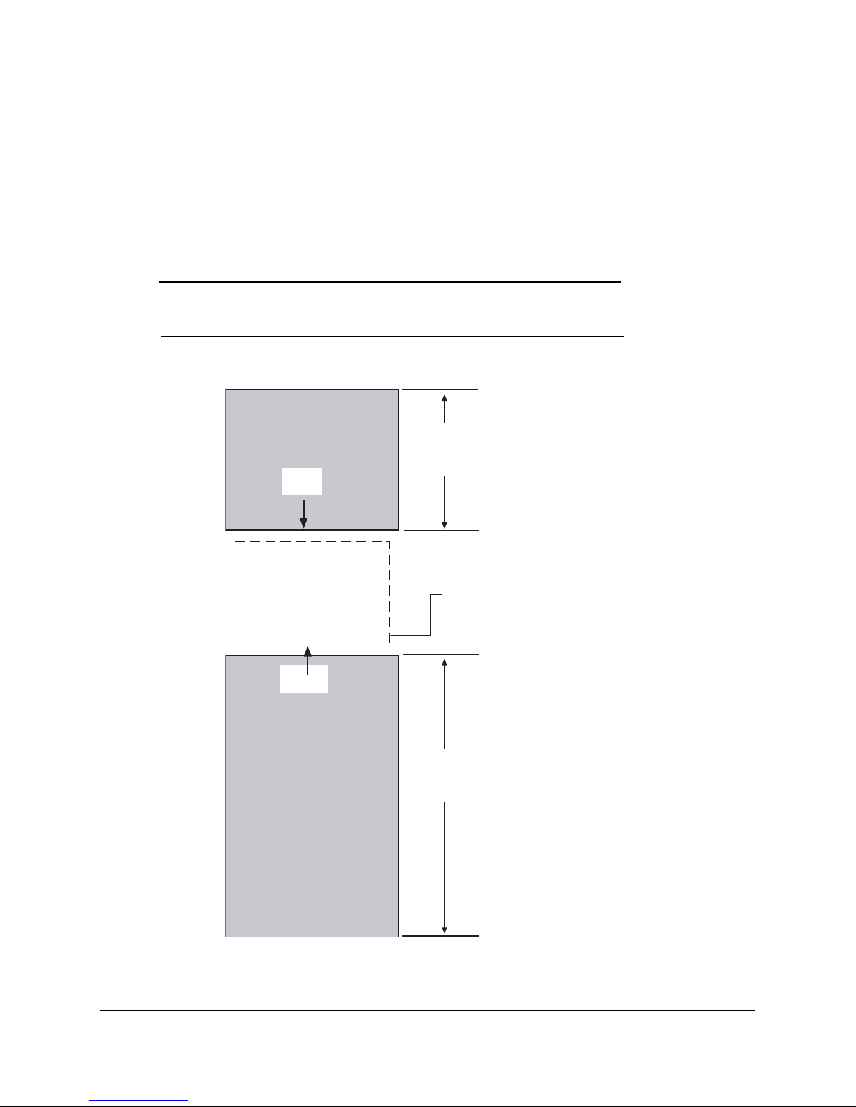
1. Where possible, provide easy access to the front and rear of the equipment rack
(Figure 2-1).
- Allow a minimum of 18 inches [45.72 mm] clearance at the rear of the
equipment rack.
- To service and maintain the equipment, allow a minimum of 36 inches of
clearance in front of the equipment rack.
Caution: Reduced Air Flow – Installation of the equipment in a rack should
be such that the amount of air flow required for safe operation of
the equipment is not compromised.
Figure 2-1 Rack Clearances – Top View
18"
[45.72 mm]
CLEARANCE
REAR
CR4 Receiver
FRONT
MOUNTING
RAILS
36"
[89.9 mm]
CLEARANCE
2-2
CodeRunner 4 Operator’s Guide 400438-1 Rev. J

Installation Prerequisites
2. Avoid direct heat to the unit. If unavoidable, use deflector plates or install the unit in
a climate controlled environment.
Caution: Elevated operating ambient temperature – If installed in a closed
3. Locate the equipment to allow for an adequate number of AC power outlets for test
equipment and power tools.
Caution: Circuit Overloading – Consideration should be given to the
4. Check that the rack mounting rails are sufficiently rigid to support the rack and
equipment.
Warning: Mechanical Overloading – Mounting of equipment in a rack should
System Installation
or multi-unit rack assembly, the operating ambient temperature of
the rack may be greater than the room ambient temperature.
Therefore, considerations should be given to the Template
Multiple Rack Assembly (TMRA).
connection of the equipment to the supply circuit and the effect
that overloading of circuits could have on over-current protection
and supply wiring. Appropriate consideration of equipment
nameplate ratings should be used when addressing this concern.
be such that a hazardous condition is not achieved due to uneven
loading.
5. Eliminate any conditions that could cause water to drip onto the equipment and
penetrate waveguide or cable openings.
2.2.1 Grounding the Equipment Rack
The equipment rack must be connected to the station ground using a #6 copper wire or
equivalent. The ground wire should be routed in as straight and direct a route as is practical.
Warning: Grounding the equipment rack is mandatory.
CodeRunner 4 Operator’s Guide 400438-1 Rev. J
2-3

System Installation
Rack Installation
2.3 Rack Installation
The MRC CodeRunner 4 mounts within a standard 19 inch equipment rack. The unit
occupies a 3 rack unit (3RU) height. The MRC CodeRunner 4 attaches to the equipment
rack using four 12–24 mounting screws. See
Figure 2-2 for the correct mounting hole
locations.
Figure 2-2 Rack Installation
MRC CodeRunner 4
MOUNTING SCREWS
For detailed information on assembling and installing a standard equipment rack, see
Section 2.4, Equipment Rack Installation on page 2-4.
2.4 Equipment Rack Installation
Step 1 Remove the top and sides of the shipping container and packaging material, free
the rack from the pallet by removing the nuts and bolts securing it in place. Refer
Table 2-1 for equipment rack specifications.
to
Table 2-1 Equipment Rack Specifications
Component Description
Finish Black baked enamel
Uprights Channel 3.0” (76.20 mm) deep x 1.4” (34.825 mm) wide x 0.25” (6.35
mm) thick.
Base Angles 4.0” (100.016 mm) high x 6.5” (162.40 mm) deep x 0.38” (9.50
mm) thick.
To p 1” (25.40 mm) high x 0.38” (9.50 mm) thick.
Step 2 Remove the rack from its crate by lifting it off the mounting bolts and place it near
its final mounting location. After the rack has been raised to a vertical position,
remove the shipping support brackets the rack side rails.
Step 3 A template can be used for marking the floor location drilling holes for anchoring
the hardware (Figure 2-3). However, if the rack is available when these holes are
drilled, it is recommended that the rack base itself be used as a template.
2-4
CodeRunner 4 Operator’s Guide 400438-1 Rev. J

Equipment Rack Installation
0
4
Figure 2-3 Equipment Rack Template
[5.34 mm]
Step 4 Hole size is determined by the type of anchor to be used. On concrete floors, use
the following hardware:
- Bolts: 3/8”, 16 x 2.
- Washers: 3/8”, Lock and flat (1 each per bolt).
- Anchors: 3/8” 16 x 2.
- Caulking Anchors:, “Diamond” type 03060,
2.125"
System Installation
1.25"
[3.175 mm]
6.00"
[15.24 mm]
3.00" [7.62 mm]
21.
[53.3
12.00"
[30.48 mm]
20.25"
[51.44 mm]
Note: These anchors require 3/4” holes. On wood floors, use 3/8” x 1 - 1/2”
lag bolts with lock and flat washers.
Step 5 Secure the rack to the adjacent racks and existing superstructure where
applicable. Fasten the rack’s top braces to the superstructure using J-bolts.
Caution: If there is not an existing superstructure, the top of the rack should
be braced to a ceiling or wall.
CodeRunner 4 Operator’s Guide 400438-1 Rev. J
2-5

System Installation
Figure 2-4 Equipment Rack – Front View
MOUNTING
HOLES
Initial Power-up Procedure
84.00"
[2.13M]
2.5 Initial Power-up Procedure
The following procedure provides instructions for initially applying power to the modem.
Before proceeding, verify the following:
Step 1 Is the other end of the communications link operational?
Step 2 Is prime power available and correct?
Step 3 Have all electrical interface connections been made?
Step 4 Are signal sources operational and correct?
2-6
CodeRunner 4 Operator’s Guide 400438-1 Rev. J
Section
3 Operating Controls
This section describes the front panel display and function screens.
3.1 Common Key Functions
Common key functions for all screens
• If the screen display dims, press any key to illuminate the screen.
• Press the Menu key to display the Menu Screen
3.2 Receiver Screens
Figure 3-1 shows the navigation scheme for the CodeRunner 4 menu screens. When the
receiver is powered up, the Main Screen is displayed (See Figure 3-2 on page 3-2).
Figure 3-1 Receiver Screens
3
AUDIO
SCREEN
VIDEO
DEMOD
SCREEN
POWER
STATUS
SCREEN
SUPPLY
MAIN SCREEN
MENU SCREEN
DIGITAL
DEMOD
SCREEN
RF TRAY
SCREEN
REMOTE
CONTROL
SCREEN
CONFIGURATION
SCREEN
MODIFY
CHANNEL
PLAN SCREEN
CodeRunner 4 Operator’s Guide
400438-1 Rev. J
3-1

Operating Controls
Receiver Screens
3.2.1 Main Screen
The Main Screen appears when the receiver is powered up. It contains the following display
options:
• Message Bar – display current software as a default. If a system error occurs, the
Message Bar displays diagnostic or error messages. For interpreting diagnostic
messages, see
Section 4, Troubleshooting on page 4-1.
• Displays Receive Frequency and Receive Signal Level (RSL).
• Channel Plan Bandwidth (12 MHz or 17 MHz)
• Local or Remote Control Mode
• IF Bandwidth:
– NRM – Normal
–NRW – Narrow
– WDE – Wide
• Change the following setting from the Main Screen:
– IF Bandwidth
– Band – 2, 7, or 13 GHz
– Channel – 1-10 (2 GHz), 1-14 (7 GHz), or 1-22 (13 GHz)
– Offset: 0, –, + or ++ (++ Offset applicable to 13 GHz band only)
Figure 3-2 Main Screen
Message Bar:
Normal display of Software Release
or Fault Message (See Note)
Frequency
CodeRunner.4 Rel. 2.00
1995.750MHz
RSL-89.2dBm Band:2
BW:NRM LOCAL Offset:–
Menu DIGITAL
To Menu Screen
Bandwidth: “NRM” (Normal)
“NRW” (Narrow)
“WDE” (Wide)
17MHz Chnl:1
“LOCAL” or “REMOTE”
Receive mode: “DIGITAL” or “ANALOG“
Band
POWER
REMOTE
SQUELCH
ALARM
Channel
Channel Offset
Receive Signal Level
Note: When any operating fault is detected, the fault message is displayed
in place of the “Software Release.”
3-2
Channel Plan (12MHz or 17MHz)
CodeRunner 4 Operator’s Guide 400438-1 Rev. J

Receiver Screens
3.2.2 Menu Screen
The Menu Screen lets you navigate to all of the following menu screens:
Figure 3-3 Menu Screen
Operating Controls
• Digital Demodulator Screen – Sets demodulator parameters, if installed.
• Power Supply Screen – Reports power supply voltage levels with features to refresh
current voltage levels.
• RF Tray Screen – Set up receiver for frequency, channel, bandwidth, and offset.
• Remote Control Screen – Use to set baud rate for dial-up or direct line from a
remote control site, to enable or disable parallel or serial interfaces, and to turn the
modem on or off.
• Configuration Screen – Adjust screen contrast, select backlight settings, and to
modify the channel plan.
• Video Demodulator Screen – Use to enable/disable the video demodulator in analog
mode, including setting the squelch point.
• Audio Demodulator Screen – Reports if audio is OK or if audio demodulator is not
installed.
“Power Supply” Screen
“Digital Demodulator”
Screen
Dig Demod Remote
Pwr Supply Config
RF Tray Video
Main Screen Audio
“Main Screen” Screen
“RF Tray” Screen
“Configuration” Screen
“Remote Control” Screen
MENU
POWER
REMOTE
SQUELCH
ALARM
“Audio Demodulator” Screen
“Video Demodulator” Screen
CodeRunner 4 Operator’s Guide 400438-1 Rev. J
3-3

Operating Controls
3.2.3 Remote Control Menu
The Remote Control Menu sets options for remotely controlling the CodeRunner 4
Receiver.
Options include:
• Transmit and Receive Baud Rate for serial remote control.
• Enabling or Disabling the Parallel Interface
• Enabling or Disabling the Serial Interface
Figure 3-4 Remote Control Menu
Serial Transmit Baud Rate
(150, 300, 1200, 4800,
9600, 19200)
Serial Receive Baud Rate
(150- 300, 1200, 4800, 9600, 19200)
Remote Control Menu
Receiver Screens
POWER
Baud Baud
Tx 9600 9600 Rx
P Rmt ENABLED
S Rmt DISABLD
Menu
Return to Main Menu
OFF
Serial Port Interface (ENABLED or DISABLD)
Modem
Modem (ON or OFF)
Parallel Port Interface (ENABLED or DISABLD)
REMOTE
SQUELCH
ALARM
3-4
CodeRunner 4 Operator’s Guide 400438-1 Rev. J

Receiver Screens
3.2.4 Configuration Screen
The Configuration Menu Screen controls the screen contrast for the Front Display. The
screen also allows access to the Channel Plan Screen.
Figure 3-5 Configuration Screen
Operating Controls
Backlight (ON or Timed)
Configuration Menu
POWER
REMOTE
Return to Main Menu
3.2.5 Modify Channel Plan Screen
The Modify Channel Plan Screen sets the Channel Plan frequency, channel, and offset and
saves the current settings.
Figure 3-6 Modify Channel Plan Screen
Cursor
Contrast
Contrast
Menu
Move Cursor Right
Modify 2GHz
02020.750
Channel
Offset
2
+
Save
Exit
BklightTimed
Mod CP
Select Modify Channel Plan Screen
Increase Screen Contrast
Decrease Screen Contrast
Move Cursor Left
<-
->
+
-
SQUELCH
ALARM
POWER
REMOTE
SQUELCH
ALARM
Exit Channel
Plan Screen
Save Settings
CodeRunner 4 Operator’s Guide 400438-1 Rev. J
Decrease Selected Digit
Increase Selected Digit
Select Channel
Select Offset
3-5

Operating Controls
3.2.6 RF Tray Screen
The RF Tray Screen sets the following parameters for operating the receiver:
• Band – 2, 7, and 13 GHz
• Channel Offset: 0, –, +, or ++ (++ Offset applicable to 13 GHz band only)
• IF Bandwidth:
– NRM – Normal
–NRW – Narrow
– WDE – Wide
• Remote Control – Enabled or Disabled
• Local Phase Lock Loop (PLL) – Lock or Unlock
• Second Downconverter – Lock or Unlock
• Receive Signal Level
• Channel Plan (Chplan) - 12 MHz or 17 MHz
Figure 3-7 RF Tray Screen
2nd Downconverter
“LOCK” or “UNLK” states
Receive Signal Level
Receiver Screens
Receive Frequency
1999.0 MHz
RSL –89.3 dBm
2 DN CNV UNLK 1 Channl
LO PLL UNLK 0 Offset
Chplan 17MHz NRM IFBW
Menu 2 BAND
Channel Plan Bandwidth
12 MHz or 17 MHz
Local Oscillator Phase Lock Loop
“LOCK” or “UNLK” states
Channel Select (See Note)
RF TRAY
POWER
REMOTE
SQUELCH
ALARM
Channel Offset
Band (2, 7, or 13 GHz)
IF Bandwidth “NRM, WDE, or NRW”
Note: The number of channels depends on the frequency band selected.
For available channels, see Appendix B, Frequencies.
3-6
CodeRunner 4 Operator’s Guide 400438-1 Rev. J

Receiver Screens
3.2.7 Power Supply Status Screen
The Power Supply Status Screen displays voltage levels. In addition, minimum and
maximum values can be reset.
Figure 3-8 Power Supply Status Screen
Operating Controls
Current Reading
Power Supply Status
Curr. Min. Max.
+15V +14.9 +14.9 +15.0
–15V –15.0 –14.9 –15.0
+5V +5.04 +4.95 +5.12
Menu Rst Min/Max
Minimum Reading
Maximum Reading
POWER
REMOTE
SQUELCH
ALARM
Resets Current Readings
CodeRunner 4 Operator’s Guide 400438-1 Rev. J
3-7

Operating Controls
3.2.8 Digital Demodulator Screen
The Digital Demodulator Screen contain the following display and command options:
• Switches between using a digital or analog demodulator. The DIGITAL setting to
active, an internal or external digital demodulator needs to be installed.
• Switches between using an internal and external digital demodulator. For the
INTERNAL setting to activate, an internal digital demodulator needs to be
installed. For the EXTERNAL setting to activate, an external digital demodulator
needs to be installed.
• Reports demodulator status: Fault, Disabled, or OK
Figure 3-9 Digital Demodulator Screen
Status Indicator
(FAULT, DISABLED, or OK)
Digital Demod
DEMOD STATUS: OK
Receiver Screens
POWER
Mode Mode:DIGITAL
Menu Demod:INTRNL
Return to Menu Screen
Note: If the Video Demodulator is not installed, the Analog mode is
disabled.
“DIGITAL” or “ANALOG” modes (See Note)
“INTRNL“ or “EXTRNL” modes
(Internal)
(External)
REMOTE
SQUELCH
ALARM
3-8
CodeRunner 4 Operator’s Guide 400438-1 Rev. J

Receiver Screens
3.2.9 Video Demodulator Screen
The Video Demodulator Screen contains the following display and command options:
Figure 3-10 Video Demodulator Screen
Operating Controls
• Receive Signal Level (RSL)
• Receiver Squelch, Digital Mode:
– Digital Mode: DISABLED
• Receiver Squelch Analog Mode:
– TRP PNT BASED – Trip Point Based
– FORCED ON
– FORCED OFF
• Set Squelch Point - Front Panel Squelch LED lights if RSL falls below squelch
point.
If Video Demod is not installed, screen Reads:
“Video Demod Not Installed”
Decrease
Squelch Level
Video Demod
VIDEO: SQUELCHED
Sql Pt -80dBm Sql Pt
Mode ANALOG
Squelch TRP PNT BASED
Menu RSL –98.7 dBm
“ANALOG” or “DIGITAL” mode
Receive Signal Level
“DIGITAL MODE” (Digital Mode)
“ON” or “SQUELCHED” (Analog Mode)
Squelch Trip Point
or
Increase
Squelch Level
“SQUELCH” LED
lights if RSL drops
below Squelch Point
(Analog Mode only)
POWER
REMOTE
SQUELCH
ALARM
Digital Mode: always “SQUELCHED”
Analog Mode: “TRP PNT BASED”
“FORCED ON”
“FORCED OFF”
Note: In analog mode, Squelch states are interpreted as follows:
CodeRunner 4 Operator’s Guide 400438-1 Rev. J
TRP PNT BASED – The video squelches based on the squelch set.
FORCED ON – The video is squelched.
FORCED OFF – The video is always on.
3-9

Operating Controls
3.2.10 Audio Screen
The Audio Screen reports status of the audio demodulator.
• Audio Mode:
– No Audio Installed
– Agile Audio
– Fixed Audio
• Audio Status: OK or FAULT
Figure 3-11 Audio Screen
“NO AUDIO INSTALLED“
“AGILE AUDIO”
“FIXED AUDIO”
(See Note)
FIXED AUDIO
Receiver Screens
POWER
AUDIO: OK
Menu
Note: Screen displays the following:
“NO AUDIO INSTALLED” – No Audio Demodulator installed.
“AGILE AUDIO” – (Future Product Option)
“FIXED AUDIO” – Audio Modulator Installed.
REMOTE
SQUELCH
ALARM
“OK" or “FAULT”
3-10
CodeRunner 4 Operator’s Guide 400438-1 Rev. J

4 Troubleshooting
This section explain how to interpret alarm indicators and messages.
4.1 Front Panel Indicators
Figure 4-1 shows the front panel LED indicators.
Figure 4-1 Front Panel LEDs
When on, indicates power to receiver
POWER
When on, indicates receiver
REMOTE
has been placed in remote mode
See Section 3.2.1, Main Screen on page 3-2
Section
4
SQUELCH
ALARM
When on, the receiver is in analog mode,
and the video is squelched.
See Section 3.2.9, Video Demodulator Screen on
When on, indicates summary alarm.
See Section 4.2, System Alarms on page 4-2
CodeRunner 4 Operator’s Guide
400438-1 Rev. J
4-1

Troubleshooting
4.2 System Alarms
Common system faults are displayed in the scrolling area of the main menu (Figure 4-2)
and in the related menu. For more information on menus, see Section 3, Operating
Controls on page 3-1.
Figure 4-2 Main Screen
SCROLLING MESSAGE AREA
System Alarms
POWER
1995.750MHz
REMOTE
RSL-89.2dBm Band:2
17MHz Chnl:1
SQUELCH
BW:NRM LOCAL Offset:–
Menu DIGITAL
Table 4-1 lists common system faults and their probable cause.
Table 4-1 System Alarms
Alarm Cause Comments
Rsl low Occurs when Received Signal Level drops below 99dBm
Synthesizer Unlocked When Local Oscillator PLL unlocks
2nd Dwn Cnv Unlocked When second down converter PLL unlocks
CH A Audio Alarm Channel A fault or agile audio card.
CH B Audio Alarm Channel B fault for agile audio card.
Audio Alarm Any Fault for Fixed Audio card.
External Demod Fault In Digital mode, external demod selected, external signal from
demod low or demod not attached.
Internal Demod Fault Digital mode, internal selected. Card fault.
Note 1 The receiver detects the difference between agile audio, fixed audio, or no audio installed.
ALARM
See Note 1
See Note 2
4-2
CodeRunner 4 Operator’s Guide 400438-1 Rev. J

Replacing the Fuse
4.3 Replacing the Fuse
The power supply fuse is accessed from the rear of the unit.
Step 1 The fuse is located on the left side of the rear panel as shown in Figure 4-3.
Step 2 Open the fuse cover.
Step 3 Remove the fuse from the receptacle and insert the new fuse using the following:
Step 4 Replace the fuse and close the fuse cover.
Figure 4-3 CodeRunner 4 Rear Panel - Typical
Troubleshooting
Warning: Disconnect power before removing cover. Service of this
equipment should only be performed by trained personnel.
- Use T2A/250V for 120 VAC Operation
- Use T1A/250V for 240 VAC Operation
FUSE
VIDEO BB
(J2)
~AC POWER
120/240; .4A
50/60 HZ
FUSE:
T1A 250 VA C
"CAUTION
DOUBLE-FUSE
NEUTRAL/FUSING"
SUM
ALARM
(J1)
AUDIO
(J12)
1
2
(J11)
3
(J15)
(J16)
4
(J3)
RX STATUS
(J13)
(J9)
PGM I/O
REMOTE
INTERF
SERIAL
PORT
ACE
(J7)
(J8)
IF I/O
815 MHz OUT
RF IN
EXT MODEMDATA OUT
CodeRunner 4 Operator’s Guide 400438-1 Rev. J
4-3

Troubleshooting
Replacing the Fuse
This page intentionally left blank.
4-4
CodeRunner 4 Operator’s Guide 400438-1 Rev. J

Section
5 Remote Operation
The receiver can be set to operate in local or remote mode using the front panel keypad and
LCD display. For the receiver to operate from a remote location, a connection must be made
between the receiver and the master antenna controller or control device. This section
describes how to assemble the control cable and interpret the various control states.
5.1 Local and Remote Operation
The receiver is set to local or remote mode using the front panel keypad and LCD. See
Section 3, Operating Controls on page 3-1.
When the receiver is set to local mode, the following conditions occur:
• All receiver functions are controlled using the front panel keypad, and remote
device commands have no effect.
• If a remote device is connected to the receiver, front panel controls override any
commands from the remote device. However, the remote device status outputs
remain functional.
When the receiver is set to remote mode, the following conditions occur:
• All receiver functions are controlled by the remote device using the interface cable.
• Commands from the remote device control all functions of the receiver and override
the front panel controls. If the remote device line connection should become open,
the receiver remains under local mode even though the device is set to remote.
• The remote setting does not force the REMOTE mode, but rather allows the remote
device to determine whether the receiver will be in the local or remote mode.
• If no remote device is connected to the receiver, the receiver will remain in local
mode, even if the front panel controls are to set to remote.
5
CodeRunner 4 Operator’s Guide
400438-1 Rev. J
5-1

Remote Operation
Command Inputs to the Remote Connector
5.2 Command Inputs to the Remote Connector
The remote device connects to the rear of the receiver using the remote interface connector
(J7) as shown in
J7 is shown in Table 5-1.
Pin functions are grouped into two categories: Control functions and Status Outputs.
Commands are sent by the remote device using the following logic states:
• The logic 1 is +5 V nominal (3.5 to 5.5 V).
• The logic 0 is 0 V nominal (-0.5 to +0.8 V) or open. Inputs have 10 K ohm pulldown resistors to ground. +5 Vdc is available at the remote interface.
A logic level of “1” is equal to +5 V, which is supplied on Pin 10 of the Remote Interface
Cable.
For remote commands to be functional, the following conditions must occur:
• The front panel control must be set to the remote mode.
• The remote mode command at J7 pin 8 must be set to 1.
• All commands must be sustained for the duration of the desired mode.
Table 5-1 Remote Interface Connections
Pin No. Function Remarks
1 GROUND GND
2 N/C
3 N/C
4 N/C
5 12/17 MHZ SCBO
6 IF BANDWIDTH LSB IFB0
7 IF BANDWIDTH MSB IFB1
8 REM CONTROL REMC
9 REM MODE STATUS REMS
10 + 5 VDC +5V
11 SQUELCH ALARM SQLA
12 SQUELCH DISABLE SQLF
13 RCL ANALOG RCLA
14 CHANNEL SEL LSB CHN0
15 CHANNEL SEL CHN1
16 CHANNEL SEL CHN2
17 CHANNEL SEL MSB CHN3
18 N/C
19 N/C
20 DIGITAL MODE SELECT DMODE
21 OFFSET SEL LSB OFS0
22 OFFSET SEL MSB OFS1
23 LNA GAIN REDUCTION GAIN
24 BAND SEL LSB BND0
25 BAND SEL MSB BND1
Appendix A, Receiver Interconnections. The combined logic table for
5-2
CodeRunner 4 Operator’s Guide 400438-1 Rev. J

Command Inputs to the Remote Connector
5.2.1 Control Functions
Table 5-2 RF Channel Selection
Function J7 Pin No.
17 16 15 14
Channel 1 0 0 0 1
Channel 2 0 0 1 0
Channel 3 0 0 1 1
Channel 4 0 1 0 0
Channel 5 0 1 0 1
Channel 6 0 1 1 0
Channel 7 0 1 1 1
Channel 8 1 0 0 0
Channel 9 1 0 0 1
Channel 10 1 0 1 0
Channel 11 1 0 1 1
Channel 12 1 1 0 0
Channel 13 1 1 0 1
Channel 14 1 1 1 0
Remote Operation
Table 5-3 Offset Selection, – Active High
Function J7 - Pin No.
22 21
- Offset 0 1
NO Offset 0 0
+ Offset 1 0
++ Offset 1 1
Table 5-4 Band Select – Active High
Function J7 Pin No.
2 GHz Band (1.99 to 2.50 and 2.3 to 2.7 GHz) 0 0
7 GHz Band (6.425 to 7.125 GHz) 0 1
12 GHz Band (12.7 to 12.95 GHz) 1 0
13 GHz Band (12.95 to 13.25 GHz) 1 1
Table 5-5 IF Bandwidth Select – Active High
Function J7 Pin No.
7 6
10 MHz (Narrow) 0 1
15 pr 20 MHz (Medium) 0 0
20 or 30 MHz (Wide) 1 0
25 24
CodeRunner 4 Operator’s Guide 400438-1 Rev. J
5-3

Remote Operation
Table 5-6 Squelch Control – Active High
Function J7 Pin No. 12
Squelch Disabled. 1
Note: The automatic squelch circuitry in the Receiver may be overridden by
Remote commands when in the REMOTE mode. Applying a logic 1
to pin 12, “SQUELCH DISABLE”, results in the receiver delivering
video and IF output independent of the quality (or presence) of
received signal.
Table 5-7 Digital Mode Select/Active High
Function J7 Pin No. 20
Digital Mode Selected 1
Table 5-8 Digital Mode Select/Active High
Function J7 Pin No. 23
High Gain Selected 1
5.2.2 Vdc Bias Supply
Command Inputs to the Remote Connector
A +5 Vdc (+/- 0.25 V) is made available on J7 pin 10 for loop-back as a command function
and for operating low power circuitry in the remote interface equipment. This output is
current limited and should not exceed 4 mA of load.
5.2.2.1 Ground
Signal (and chassis) ground is made available on J7 pin 1 for loop-back as a command
function and as the return for the +5 V bias supply.
5.2.3 Status Outputs – Remote Connector J7
Status outputs are functional in both LOCAL and REMOTE modes.
5.2.3.1 Receiver Signal Strength Indication - Analog
A buffered S meter output is made available on J7 pin 13.
• No signal strength (no RF input) = 0 V.
• Maximum signal strength (-35 dBm RF input) = +1V. Output impedance is 1 K
ohm.
5.2.3.2 Remote Mode Status
Active Low - J7 Pin 9
• Ground = Receiver is in the REMOTE control mode
• Open circuit = Receiver is in the LOCAL control mode.
5.2.3.3 Squelch Alarm
Dry Contact Closure - J7 Pin 11 to Ground (Pin 1).
• Open circuit = Receiver is operating correctly with an adequate received signal.
• Contact closure = Receiver has squelched video output due to inadequate received
signal.
A contact closure (i.e., alarm) also occurs when the Receiver is turned OFF.
5-4
CodeRunner 4 Operator’s Guide 400438-1 Rev. J

Section
6 Media Switch
6.1 Overview
The optional Media Switch lets operators switch between analog and digital modes where
both applications are used. The switch provides for separate video and audio or for
baseband composite.
The Front Panel Keypad and Display controls the operating mode as shown in Figure 3-10,
Video Demodulator Screen on page 3-9. The same “IF CNTRL” signal used to change
modes in the receiver is routed to the media switch using an optional cable allowing
simultaneous switching between both the analog and digital sources.
Figure 6-1shows a block diagram of the CR4 Receiver and Media Switch when used with
the Alteia Receiver for switching both video and audio.
Figure 6-1 Media Switch Block Diagram
VIDEO
ALTEIA
RECEIVER
AUDIO
6
CodeRunner 4
RECEIVER
DISPLAY
RF SHELF
IF
VIDEO
DEMODULATOR
AUDIO
DEMODULATOR
IF
VIDEO
AUDIO
(D)
(A)
IF
IF
CNTRL
MEDIA
SWITCH
(D)
(A)
(D)
(A)
VIDEO
OUT
AUDIO
OUT
(4 CHAN.)
CodeRunner 4 Operator’s Guide
400438-1 Rev. J
6-1

Media Switch
DIGITAL AUDIO IN
ANALOG AUDIO IN
Mounting the Media Switch
6.2 Mounting the Media Switch
The Media Switch attaches to the rear panel of the CodeRunner 4 Receiver using
5mounting screws as shown in
• Media Switch and Connector Assembly (906896)
• Audio Cable - Analog and digital audio outputs (906978)
• Remote Control Cable - Change analog or digital IF state (907008)
Figure 6-2 Media Switch on CR4 Rear Panel
VIDEO
(J2)
AC
INPUT
1
2
3
4
BB
(J1)
AUDIO
ALARM
(J3)
(J12)
(J11)
(J15)
(J16)
Figure 6-2. It requires the following components:
SUM
VIN
1
V
OUT
VIN
2
BBIN
1
BB
OUT
DIGITAL AUDIO IN
ANALOG AUDIO IN
BBIN
2
OUT
AUDIO 4
AUDIO 3AUDIO 2
OUT OUT
OUT
AUDIO 1
POWER/
CONT
RX STATUS
(J13)
(J9)
PGM I/O
REMOTE
INTERFACE
SERIAL
PORT
(J7)
(J8)
DATA OUT
IF I/O
815 MHz OUT
RF IN
EXT MODEM
MEDIA SWITCH
ASSEMBLY
MOUNTING SCREWS
(5 PLACES)
6.3 Media Switch Connections
Figure 6-3 shows the locations of the input and output connections.
Figure 6-3 Media Switch Connections
VIDEO INPUT 1
VIDEO OUTPUT
VIDEO INPUT 2
ANALOG & DIGITAL
AUDIO INPUTS
(4 ANALOG CHANNELS &
4 DIGITAL CHANNELS)
POWER/IF CONTROL
AUDIO OUTPUT
(4 CHANNELS)
BASEBAND INTPUT 1
BASEBAND OUTPUT
6-2
BASEBAND INPUT 2
CodeRunner 4 Operator’s Guide 400438-1 Rev. J

System Interconnection
OUT
AUDIO4
VIN
2
POWER/
V
OUT
1
VIN
CONT
OUT
AUDIO1
OUT
AUDIO3
OUT
AUDIO2
OUT
DIGITAL AUDIO IN
BBIN
2
BB
BBIN
1
ANALOG AUDIO IN
A
UDIO #2
RIGHT/AES/EBU
A
UDIO #1
RIGHT/AES/EBU
A
UDIO #2 LEFT
A
UDIO #1 LEFT
DIGIT
AL
VIDEO
ANALOG
VIDEO
GENLOCK
MPLC-2-SPI-TSO
RS-232 D ATA
RX-422 DATA
RCTRL RX 232/485
RF INPUT
BB INPUT
6.4 System Interconnection
Figure 6-4 shows a typical interconnection between the CR4 REceiver, Media Switch, and
the Alteia Receiver. In this configuration, separate audio and video sources are switched.
For more information on the Alteia Receiver, see the following manual:
• Alteia Instruction Manual – ST.TM.E9200.2R1
Figure 6-4 System Interconnection
Figure 6-6, Audio Harness (906978) on page 6-4
Figure 6-5, Power & IF Control Harness (907008) on page 6-4
VIDEO OUTPUT
(ANALOG)
Media Switch
RF INPUT
VIDEO
AC
INPUT
BB INPUT
AUDIO
RX-422 D
BB
1
2
3
4
MPLC-2-SPI-TSO
SUM
ALARM
ANALOG AUDIO IN
RS-232 D
VIN
1
V
OUT
VIN
2
BBIN
1
BB
OUT
DIGITAL AUDIO IN
BBIN
2
RCTRL RX 232/485
AUDIO4
AUDIO3
AUDIO2
AUDIO1
POWER/
CONT
OUT
OUT
OUT
OUT
RX STATUS
GENLOCK
PGM I/O
DIGIT
ANALOG
REMOTE
INTERFACE
SERIAL
PORT
AL
VIDEO
VIDEO
UDIO #1 LEFT
AUDIO OUTPUT
(4 CHANNELS)
DATA
OUT
UDIO #1
RIGHT/AES/EB
UDIO #2 LEFT
IF I/O
UDIO #2
RIGHT/AES/EB
815 MHz OUT
RF IN
EXTERNAL
MODEM
CodeRunner 4 Operator’s Guide 400438-1 Rev. J
6-3

Media Switch
6.5 Harness Assemblies
Figure 6-5 Power & IF Control Harness (907008)
7.00 ± .25"
[17.78 mm ± .635 mm]
5.00 ± .25"
[12.70mm ± .635 mm]
N/C
6
N/C
5
N/C
4
ORN
+15V
GND
IF CNTRL
3
2
1
BLK
WHT/RED
1
Harness Assemblies
158
+15V
GND
IF CNTRL
1
9
8
14
4
ORN
BLK
WHT/RED
CABLE ASSY, CONTROL
Figure 6-6 Audio Harness (906978)
72.00 ±3.00
1
251413
11X
5.0
WIRING DIAGRAM
ANALOG
1
2
3
4
5
6
7
8
9
10
11
12
13
AUDIOT/RP/O #1
21
2
2
2
2
2
2
2
2
2
2
2
N/C
PIN
1
2
3
1
2
3
2
1
3
2
1
3
COLOR
RED
YEL1
BLK1
GRN2
YEL2
BLK2
WHT3
YEL3
BLK3
BLU4
YEL4
BLK4
USAGE
CR-4
CR-4
CR-4
CR-4
CR-4
CR-4
CR-4
CR-4
CR-4
CR-4
CR-4
CR-4
P/O #1
T/R
14
1
15
1
1161
17
1
18
1
19
1
20
1
21
1
22
1
1234
24
1
25
1
DIGITAL
AUDIO
1
1
2
2
2
3
3
3
4
4
PIN
3
1
3
1
2
3
1
2
3
2
1
2
7.00 +/-.50
6.00 +/-.50
8X
COLOR
RED
YEL
BLK
GRN
YEL
BLK
WHT
YEL
BLK
BLU
YEL
BLK
8X
USAGE
FUTURE
FUTURE
FUTURE
FUTURE
FUTURE
FUTURE
(MEDIA SWITCH)
CM-4
CM-4
CM-4
CM-4
CM-4
CM-4
AUDIO CABLE FOR MEDIA SWITCH
BLU
YEL
GRN
YEL
B
W
HT
B
L
K
BLU
B
YEL
LK
WIRE HARNESS ASSY
TR/1
AUDIO 4
EL
Y
LK
B
L
RED
GRN
K
YEL
TR/1
T
H
AUDI O 3
W
EL
Y
BLK
LK
B
BLK
D
E
R
Y
E
L
1
2
3
1
2
3
1
2
3
TR/2
AUDIO 4
BLK
YEL
1
2
3
1
3
2
TR/2
AUD
TR/2
AUDIO 3
DIGITAL
TR/1
AUDIO 2
TR/1
3
AUDIO 1
21
TR/2
AUDIO 1
IO 2
ANALOG
6-4
CodeRunner 4 Operator’s Guide 400438-1 Rev. J
Appendix
1
2
AC
INPUT
REMOTE
INTERFACE
IF
OUTPUT
SERIAL
PORT
REMOTE
INTERFACE
DATA
OUTPUT
RECEIVER
STATUS
SUMMARY
ALARMS
PGM
I/0
AUDIO
1 THRU 4
VIDEO
BASEBAND
OUTPUT
RF
INPUT
EXTERNAL
MODEM
GROUND
CONNECTION
A Receiver Interconnections
A.1 Cabinet Connections
This appendix shows the cabinet enclosure internal and external connections. Refer to the
following diagrams:
• Figure A-1, CodeRunner Rear Panel Connectors - Typical, on page A-1
• Figure A-2, Receiver Interconnection Diagram - RF Shelf, on page A-4
• Figure A-3, Receiver Interconnection Diagram - Backplane, on page A-5
Figure A-1 CodeRunner Rear Panel Connectors - Typical
A
OUTPUT
(J2)
(J1)
VIDEO
3
4
BB
AUDIO
SUM
ALARM
(J12)
(J11)
(J15)
(J16)
(J3)
(J13)
RX STATUS
(J9)
PGM I/O
SERIAL
PORT
(J8)
(J7)
DATA OUT
IF I/O
815 MHz
OUTPUT
815 MHz OUT
RF IN
EXT MODEM
CodeRunner 4 Operator’s Guide
400438-1
Rev. J
A-1

Receiver Interconnections
A.2 Remote Interface Connector
Table A-1 Remote Interface Connections (J7)
Pin No. Function Remarks
1 GROUND GND
2 SUB CXR A MSB SCA1
3 SUB CXR A LSB SCA0
4 SUB CXR B MSB SCB1
5 12/17 MHZ SCB0
6 IF BANDWIDTH LSB IFB0
7 IF BANDWIDTH MSB IFB1
8 REM CONTROL REMC
9 REM MODE STATUS REMS
10 + 5 VDC +5V
11 SQUELCH ALARM SQLA
12 SQUELCH DISABLE SQLF
13 RCL ANALOG RCLA
14 CHANNEL SEL LSB CHN0
15 CHANNEL SEL CHN1
16 CHANNEL SEL CHN2
17 CHANNEL SEL MSB CHN3
18 N/C
19 N/C
20 DIGITAL MODE SELECT DMODE
21 OFFSET SEL LSB OFS0
22 OFFSET SEL MSB OFS1
23 LNA GAIN REDUCTION GAIN (future use)
24 BAND SEL LSB BND0
25 BAND SEL MSB BND1
Remote Interface Connector
A-2
CodeRunner 4 Operator’s Guide 400438-1 Rev. J

Remote Interface Connector
Table A-2 Serial Port (J8)
PIn # Description Comment
1 NA
2 SERP3
3 SERP1
4 NA
5 NA
6 GND
7 SERP2
8 SERP0
9 NA
Table A-3 Summary Alarm (J3)
PIn # Description Comment
1 LOF_X
2 M_SUM_X
3 +5V
4 Relay COMM
5 Relay N/O
6 NC
7 GND
8 NC
9 Relay N/C
Receiver Interconnections
Table A-4 Rx Status (J13)
PIn # Description Comment
1 SCA_FAULT
2 SCB_FAULT
3 AN_EN
4 IF_CNTRL
5 N/U
6 MW_LK
7 AGC
8 +15V
9 –15 V
10 RXSUM
11 M_SUM_X
12 M_SUM_I
13 IF_LK
14 GND
15 +5V
CodeRunner 4 Operator’s Guide 400438-1 Rev. J
A-3

Receiver Interconnections
E
Figure A-2 Receiver Interconnection Diagram - RF Shelf
BNC-F
REAR PAN
806440-11
+5 DBM
+5 DBM
Remote Interface Connector
906587-1
IF AMP
845133-5
IF FILTER
906789/906776
845133-7
EQL
BPF
+6 DB
MODE
RUN IN DIGITAL
SQUELCH LOGIC
LINEAR AGC
&
V
D
V
AGC
EQL
BPF
906611-4
906840-5
EQL
SW CTRL
BPF
+15V
GND
BW0
BW1
SELA - WHT
900344-6
SELB - BLU
MODEM
DIGITAL
TO
J3
J2
J4
BC
BNC-F
REAR PANEL
2ND DOWN CONV
815 MHZ
12 dB
LNC
906768/906756
COUPLER
2-1
90674
"SMA"
"N"
52190-1 & 89396-11
BPF
+24 DB
745/885 MHZ
+15V
GND
LO
0 - WHT
FREQ-BLU
LOHL
IF_LK
IF_CTRL
POWER
DISTRIBUTION
834
906
TO
DEMOD
VIDEO
A
Continued on Figure A-3 on page A-5
SCLK
SDAT
SEN1
MW_LK
VTUNE
+15V
LO
GND
906839-5
906752/906734
SYNTHESIZER
TO BACKPLANE
906888-9
SER PLL
2.75
906670-
A-4
CodeRunner 4 Operator’s Guide 400438-1 Rev. J

Remote Interface Connector
Figure A-3 Receiver Interconnection Diagram - Backplane
Continued from Figure A-2 on page A-4
Receiver Interconnections
900344-15/16
IF IN
901358-n
+15V
-15V
ANALOG
GND
B/B
B
VID
SCXR
TO
AN_EN
AGC
IF AMP
NOTE: CONNE CTS
BB OUT
SYNTHESIZER
BNC-F
RE AR PANEL
TO J2 WHEN NO
INTE RNAL MODEM
VIDEO OUT
2ND DC
IF FILTER
IF 2 OUT
123
AGC IF
902571-nn
AUDIO 2
AUDIO 1
123
INTER NAL MODEM
EXTERNA L MODEM
DUAL AUDIO
AF1A
AF1B
AF2A
AF2B
900414-1/900172-n
ANALOG DEM OD
POWER DIST
SCXR
AUDIO
+15V
-15V
GND
REMOTE
ALARM RELA Y
ACLK
AEN1
ADAT
SCA_FAULT
SER CHN
AEN2
845133-10/1
MODEM
906748
POWER SU PPLY
IF IN
C
+15V
-15V
+5V
+9V
BNC-F
REAR PANEL
DATA OUT
DATA OUT
GND
M_SUM_I
M_P-I
902571-nn
906800
PWR SUPPLY
RXSUM
+15V
348
-15V
+5V
AC LINE
+9V
+24VSQLS
1
GND
ACLK
AEN1
AEN2
AGC
LOHL
SDAT
SCLK
SEN1
BW0
BW1
MW_LK
IF_LK
LOF_I
M_SUM_I
LOF_X
M_SUM_X
M_SUM_I
LOF_X
M_SUM_X
RX STATUS
AN_EN
RXSUM
SCA_FAULT
IF_CTRL
SCB_FAULT
-15V
BOARD
DISTRIBUTION
TO POWER
Continued from Figure A-2 on page A-4
A
51700-35
51700-36
AGC
+15V
+5V
815714613512411310291
RELAYS
BAND SELECT
GND
MW_LK
IF_LK
LOF_I
LMTR
AN_EN
SCA_FAULT
SCB_FAULT
594837261
ADAT
+5V
SUMMARY ALARM I/O
M_SUM_X
GND
TXDR
RXDR
LOF_X
RXSUM
SQLS
SERP0
SERP1
SERP0
SERP1
SERP2
SERP3
SERP2
SERP3
+15V
-15V
+5V
SQLA
+9V
GND
AGC
TXDR
MICRO-P
+5V
GND
123456789
J6
123456789101112131415
RXDR
+5V
GND
AGC
SQLA SQLA
TXDR
RXDR
SERP0
10111213141516
SQUELCH REL AY
SERP1
SERP2
906828906826
BACKPLANE
SERP3
16
7
REMOTE I/O
12345
SCA0
SCA1
CHN1
GND
CHN0
J9
PGM I/O
MICROCONTROLLER
906146
DISPLAY
J8
SER PORT
9 PIN D M
594837261
RCLA
BND1
SQLD
BND0
SQLA
GAIN
OFS1
REMS
OFS0
REMC
GND
J7
25 PIN D
REMOTE INTERFACE
+5V
13251224112310229218207196185174163152141
IFB1
DMODE
IFB0
CHN3
SCB0
CHN2
SCB1
CodeRunner 4 Operator’s Guide 400438-1 Rev. J
A-5

Receiver Interconnections
Remote Interface Connector
This page intentionally left blank.
A-6
CodeRunner 4 Operator’s Guide 400438-1 Rev. J

B.1 Channel Frequencies
Refer to the following tables for a list the U.S. domestic frequency channels.
• 2 GHz (17 MHz Channel Plan) - Table B-1 on page B-1
• 2 GHz (12 MHz BAS Channel Plan) - Table B-2 on page B-2
•7 GHz - Table B-3 on page B-2
•13 Ghz - Table B-4 on page B-3
Note: When powering on the receiver, and when switching to another RF channel, there is a delay
until phase lock of the synthesizer occurs.
Table B-1 2 GHz Channel Guide (17 MHz Channel Plan)
Channel Offset Switch Position
Appendix
B Frequencies
B
Frequency
Band
2 GHz
(-)
Channel
1 1995.75 1999.00 2003.25
2 2012.25 2016.50 2020.75
3 2029.25 2033.50 2037.75
4 2046.25 2050.50 2054.75
5 2063.25 2067.50 2071.75
6 2080.25 2084.50 2088.75
7 2097.25 2101.50 2105.75
8 2454.25 2458.50 2462.75
9 2471.25 2475.50 2479.75
10 2487.75 2492.00 2496.25
Offset
(MHz)
(0) Offset
(MHz)
(+) Offset
(MHz)
CodeRunner 4 Operator’s Guide
400438-1
Rev. J
B-1

Frequencies
Table B-2 2 GHz Channel Guide (12 MHz BAS Channel Plan)
Channel Offset Switch Position
Channel Frequencies
Frequency
Band
2 GHz
Table B-3 7 GHz Channel Guide
Frequency
Band
Channel
1 2028.50 2031.50 2034.50
2 2040.50 2043.50 2046.50
3 2052.50 2055.50 2058.50
4 2064.50 2067.50 2070.50
5 2076.50 2079.50 2082.50
6 2088.50 2091.50 2094.50
7 2100.50 2103.50 2106.50
8 2454.25 2458.50 2462.75
9 2471.25 2475.50 2479.75
10 2487.75 2492.00 2496.25
Channel
(-)
Offset
(MHz)
Channel Offset Switch Position
(-)
Offset
(MHz)
(0) Offset
(MHz)
(0) Offset
(MHz)
(+) Offset
(MHz)
(+) Offset
(MHz)
7 GHz
1 6881.25 6887.50 6893.75
2 6906.25 6912.50 6918.75
3 6931.25 6937.50 6943.75
4 6956.25 6962.50 6968.75
5 6981.25 6987.50 6993.75
6 7006.25 7012.50 7018.75
7 7031.25 7037.50 7043.75
8 7056.25 7062.50 7068.75
9 7081.25 7087.50 7093.75
10 7106.25 7112.50 7118.75
11 6431.25 6437.50 6443.75
12 6456.25 6462.50 6468.75
13 6481.25 6487.50 6493.75
14 6506.25 6512.50 6518.75
B-2
CodeRunner 4 Operator’s Guide 400438-1 Rev. J

Channel Frequencies
Table B-4 13 GHz Channel Selection Guide
Channel Offset Switch Position
Frequencies
Frequency
Band
13 GHz
(-)
Channel
1 12706.25 12712.50 12718.75 12725.00
2 12731.25 12737.50 12743.75 12750.00
3 12756.25 12762.50 12768.75 12775.00
4 12781.25 12787.50 12793.75 12800.00
5 12806.25 12812.50 12818.75 12825.00
6 12831.25 12837.50 12843.75 12850.00
7 12856.25 12862.50 12868.75 12875.00
8 12881.25 12887.50 12893.75 12900.00
9 12906.25 12912.50 12918.75 12925.00
10 12931.25 12937.50 12943.75 12950.00
1 12956.25 12962.50 12968.75 12975.00
2 12981.25 12987.50 12993.75 13000.00
3 13006.25 13012.50 13018.75 13025.00
4 13031.25 13037.50 13043.75 13050.00
5 13056.25 13062.50 13068.75 13075.00
6 13081.25 13087.50 13093.75 13100.00
7 13106.25 13112.50 13118.75 13125.00
8 13131.25 13137.50 13143.75 13150.00
9 13156.25 13162.50 13168.75 13175.00
10 13181.25 13187.50 13193.75 13193.75
11 13206.25 13212.50 13218.75 13218.75
12 13231.25 13237.50 13243.75 13243.75
Offset
(MHz)
(0)
Offset
(MHz)
(+)
Offset
(MHz)
Offset
(++)
(MHz
CodeRunner 4 Operator’s Guide 400438-1 Rev. J
B-3

Frequencies
Channel Frequencies
This page intentionally left blank.
B-4
CodeRunner 4 Operator’s Guide 400438-1 Rev. J

Appendix
CModules
This appendix contains adjustments and indicators for the receiver modules. Figure C-1shows the chassis overview
of the receiver.
Figure C-1 Receiver Components - Top View
LOW NOISE
CONVERTER
12 dB
COUPLER
IN
CPL
OUT
2ND
DOWN CONVERTER
IF AMP
IF FILTER
REMOTE
INTERFACE
BOARD
BACKPLANE
BOARD
AC
POWER
RECEPTACLE
C
POWER
DISTRIBUTION
BOARD
LOCAL
OSCILLATOR
CodeRunner 4 Operator’s Guide
(CABLE
TO
FRONT PANEL)
400438-1
POWER
SUPPLY
Rev. J
VIDEO
DEMODULATOR
AUDIO
DEMODULATOR
C-1

Modules
VIDEO GAIN ADJUSTMENT
BASEBAND GAIN ADJUSTMENT
SQUELCH THRESHOLD ADJUSTMENT
SQUELCH LED (RED = SQUELCHED)
J1
1
15
J1
FRONT
VIEW
906556
R88
R54
R55
R88
R54
R55
C.1 Rx Video Demodulator
Note: All other adjustments are factory set and should not be adjusted.
Figure C-2 Rx Video Demodulator Adjustments
J2
Rx Video Demodulator
J2
C-2
CodeRunner 4 Operator’s Guide 400438-1 Rev. J
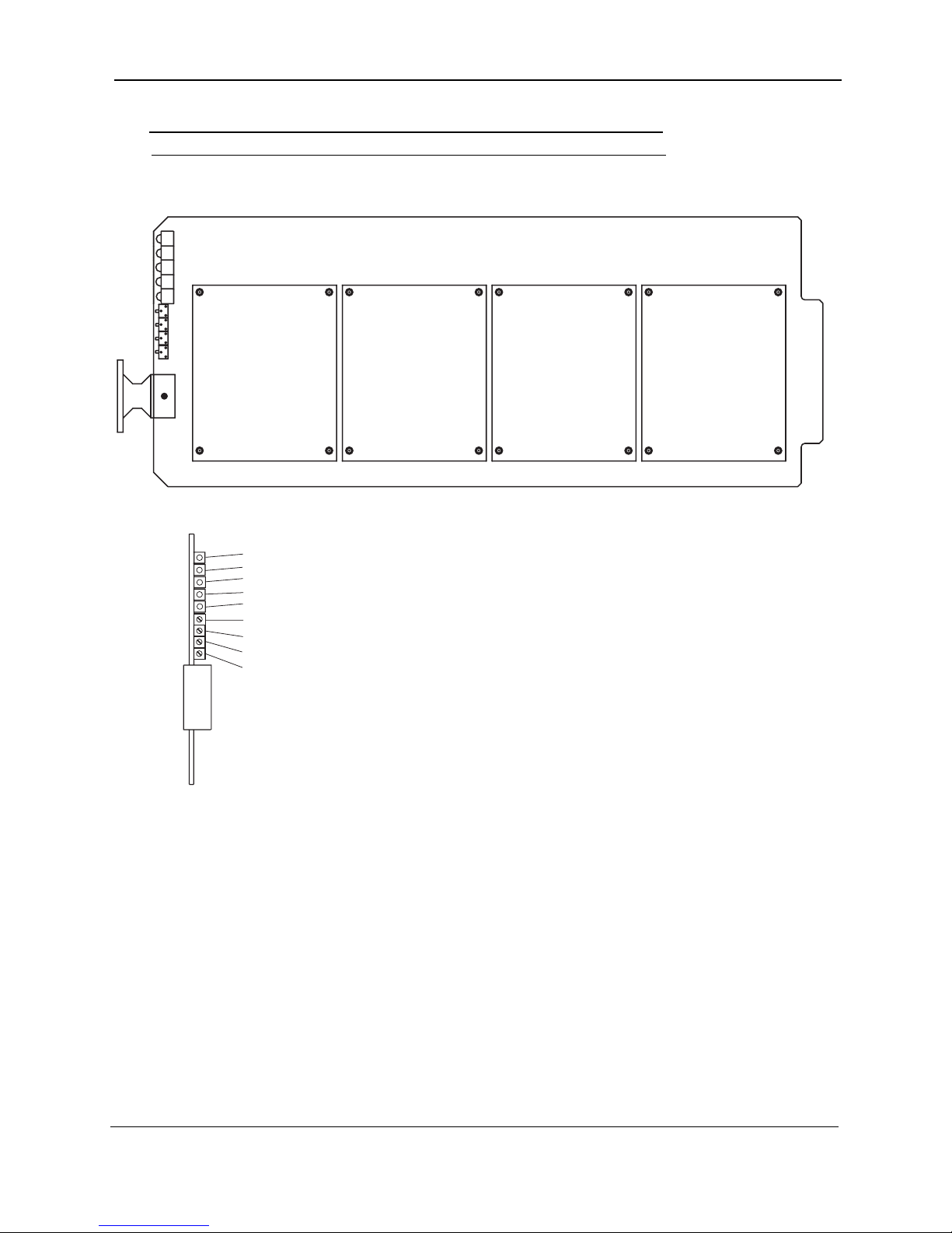
Audio SubCarrier Motherboard
X6
X11
X7
X5
C.2 Audio SubCarrier Motherboard
Note: All other adjustments are factory set and should not be adjusted.
Figure C-3 Audio Subcarrier Motherboard
R1
R2
R3
R4
CHANNEL 4
CHANNEL 3 CHANNEL 2
Modules
CHANNEL 1
X11
X7
X6
X5
Audio 1 Subcarrier Phase Lock LED
Audio 2 Subcarrier Phase Lock LED
Audio 3 Subcarrier Phase Lock LED
Audio 4 Subcarrier Phase Lock LED
Summary Alarm LED
R1 - Audio 1 Output Level Adjust
R2 - Audio 2 Output Level Adjust
R3 - Audio 3 Output Level Adjust
R4 - Audio 4 Output Level Adjust
FRONT VIEW
CodeRunner 4 Operator’s Guide 400438-1 Rev. J
C-3

Modules
Audio SubCarrier Motherboard
This page intentionally left blank.
C-4
CodeRunner 4 Operator’s Guide 400438-1 Rev. J

Appendix
DAntenna Configurations
D.1 Overview
The following figures show switched and un-switched antenna configurations for steerable antennas using
dual analog and digital audio and video.
Figure D-1 Central Receive - Analog/Digital
D
MRC
UltraScam
ProScan
or
MicroScan
SLAVE
CONTROLLER
ASC-140
Com
J2
Summary
Alarms
ANTENNA
CTN
Standard
Remote
Interface
RF
CodeRunner 4
Serial
COFDM
Decoder MPEG II
Central
Receive
System
CR4
Central RX
70 MHz IF
RF
Cable
Analog
Audio &
Video
Demod
(Optional)
Video
Video
2 Audio
CodeRunner 4 Operator’s Guide
400438-1
Audio
Rev. J
D-1

Antenna Configurations
Figure D-2 Central Receive with Analog/Digital Media Switch
MRC
UltraScam
ProScan
or
MicroScan
ANTENNA
CTN
RF
RF
Cable
Analog
Mode
/
Digital
Selection
Overview
ASC-140
Slave
Controller
Sum Alarm
Post Veterbi Alarm
Post Veterbi Meter
These functions are
dependent upon Master/
Slave capability.
Harness provided for
TS-940/ASC-140.
CodeRunner 4
CR4
Central RX
Optional FMR
70 MHz IF
COFDM
Decoder MPEG II
Central RX
System
Analog
Audio &
Video
Demod
(Optional)
Video
2
Audio
Video
2 Audio
Media
Switch
Video /
Audio
(Mounted on
CR4)
Video
2 Audio
D-2
CodeRunner 4 Operator’s Guide 400438-1 Rev. J
 Loading...