

Page 1

DS-2
IF Diversity Switch
Table of Contents
Section 1 - System Overview
Section 2 - System Installation
Document: 400462-1
Revision A
March 2001
Operator’s Guide
Page 2

PR
OPRIETARY NOTICE
The information and design contained within this manual was originated by and is the property of
Microwave Radio Communications. Microwave Radio Communications reserves all patent
proprietary design, manufacturing, reproduction use, and sales rights thereto, and to any articles
disclosed therein, except to the extent rights are expressly granted to others. The foregoing does
not apply to vendor proprietary parts.
To allow for the introduction of design improvements, specifications are subject to change without
notice.
©2001 Microwave Radio Communications
Printed in the U.S.A.
March 2001
Revision Date
A March 2001
Microwave Radio Communications
101 Billerica Avenue – Bldg 6
North Billerica, MA 01862-1256
USA
TEL: (978) 671-5700
FAX: (978) 671-5800
Page 3

Impor
tant Safeguards
Caution:
1. Read all of these instructions.
2. Save these instructions for later use.
3. Follow all warnings and instructions
marked on the units.
Read Instructions - All safety and
operating instructions should be carefully
1
read before operating the equipment.
Retain Instructions - The safety and
operating instructions should be retained
2
and stored in a convenient place for future
reference.
Heed Warnings - All warnings on this
equipment, and in the operating instructions
3
should be strictly adhered to.
Follow Instructions - All operating and user
instructions should be properly
4
implemented for optimum and safe
performance.
Cleaning - Do not use liquid cleaners or
aerosol cleaners. Instead, use only a damp
5
cloth for cleaning.
Attachments - Do not use attachments not
authorized by Microwave Radio
6
Corporation. Using unauthorized
attachments may create safety hazards or damage
the equipment.
Water and Moisture - Indoor equipment is
not designed to withstand water or moisture
7
beyond the limits noted in the product
specifications.
Accessories - Do not place equipment on
an unstable cart, stand, tripod, bracket, or
8
table. The product could fall, causing
serious personnel injury or damage the equipment.
Use only equipment recommended by Microwave
Radio Corporation. When mounting or installing the
equipment, follow the manufacturer's instructions.
Grounding or Polarization - AC powered
10
This plug fits into a standard, grounded power outlet.
If you are unable to insert the plug into the outlet,
contact your electrician to replace your obsolete
outlet. Do not defeat the safety purpose of the
grounded plug.
11
equipment items. Pay particular attention to cords at
plugs, convenience receptacles, and at the point
where they enter and exit the equipment.
12
can result in fire or electric shock.
13
following conditions occur:
1. If the power supply cord or plug has been
damaged.
2. If liquid has been spilled in the equipment, or
objects have fallen into the equipment.
3. If the equipment does not operate normally by
following the operating instructions and adjusting
only those controls that are covered by the oper ating
instructions. Improperly adjusting or tampering with
controls not covered in the operating instructions
may result in damage to the equipment or require
extensive work by a qualified technician to restore
the radio to its normal operation.
When the equipment exhibits a distinct change in
performance indicating the need for service.
14
Unauthorized substitutions could result in fire,
electric shock, or damage to the equipment.
versions of this product are equipped with a
3-wire plug with an integral grounding pin.
Power Cord Protection - Power supply
cords should be routed so that they are not
likely to be walked on or pinched by other
Object or Liquid Entry - Never spill liquids
or insert objects of any kind through
openings in the equipment. Such actions
Damage Requiring Servic e - Unplug the
radio product from the power outlet and
contact service personnel when the
Replacement Parts - When replacing
parts is required, use only parts authorized
by Microwave Radio Corporation.
Power Sour ces - The equipment should be
operated only from the type of power source
9
indicated on the unit, or in the operating
instructions. For 220 VAC operation, the proper
power cord must be used.
Safety Check - Upon completing any
15
determine that the equipment is in proper operating
condition.
service or repairs to the equipment, ensure
that safety checks are performed to
Page 4

Notes
Page 5

Preface
Purpose
This manual explains how to install, operate, and configure the DS2 Diversity Switch. It
also provides troubleshooting information in order to remedy common system faults.
Audience
This manual is intended for qualified installers and service technicians who need to perform
the following tasks:
• Install the DS2 Diversity Switch in a standard equipment rack.
• Power up the unit and verify normal operation.
• Troubleshoot common system faults.
For commonly used abbreviations and acronyms, see the Glossary on page vi.
Related Documents
FLH–DAR Operator’s Guid e — Instructions for installing and calibrating the FLH–DAR
transmitter and receiver.
Organization
This manual is divided into the following sections and appendices:
Section 1
Section 2
System Overview - Describes the operating specifications and theory of
operation for the DS2 Diversity Switch.
System Installation - Describes how to install the DS2 Diversity Switch in a
standard equipment rack. Also included are power connections for both AC
and DC power configurations, as well as how to initially power up the
modem.
IF Diversity Switch Operator’s Guide
400462-1
Rev. A
v
Page 6

Preface
Glossary
This section describes commonly used acronyms and abbreviations used in
telecommunication and those specific to Microwave Radio Communications.
Term Definition
ØLK
1RU
A & C
ADPCM
AFC
AGC
AIS
AMI
AVG
B3ZS
B8ZS
BER
BNC
BPF
BPS
CCITT
Composite
dBm
DMUX,
DEMUX
DS3
Duplex
EIA
EMC
EOW
ERRS
ESD
Phase Lock.
1 Rack Unit height.
Alarm and Control.
Adaptive Differential Pulse Code Modulation.
Automatic Frequency Control.
Automatic Gain Control.
Alarm Indication Signal (all one’s).
Alternate Mark Inversion, line code format for traffic data.
Average.
Bipolar 3 Zero Substitution, line code format for traffic data.
Bipolar 8 Zero Substitution, line code format for traffic data.
Baseband.
Bit Error Rate.
Bayonet lock coaxial connector.
Band Pass Filter.
Bits per second.
International Telegraph and Telephone Consultative Committee, a
telecommunications standardizing committee of the ITU.
A band or grouping of frequencies and/or subcarriers, including video,
occupied by the signal in a radio transmission system. Same as
baseband signal.
Decibel.
A unit of power measurement referenced to one milliwatt.
Demultiplexer
45 Mbps traffic rate
A channel capable of transmitting information simultaneously in either
direction.
2.048 Mbps traffic rate.
34 Mbps traffic rate
Electronic Industries Association, an industry association that
establishes various standards.
Electromagnetic compatibility.
Engineering Order Wire.
Errors.
Electrostatic discharge.
BB
dB
E1
E3
vi
IF Diversity Switch Operator’s Guide
400462-1 Rev. A
Page 7

Preface
Term Definition
FCC
FEC
FIFO First in, first out buffer.
FIR Finite Impulse Response.
FLR MRC's model designation for frequency modulated (FM) remodulating
FPGA Field Programmable Gate Array.
GND Ground.
H/W Hardware.
HDB3 High Density Bipolar 3 line code format for traffic data.
HPF High Pass Filter.
I In phase
ID Identification.
IF Intermediate Frequency.
IRE 1. Institute of Radio Engineers, an international professional radio
Kbps Kilobits per second.
KHz Kilo (1,000) cycles per second.
LCD Liquid Crystal Display
Lcl Local
LED Light emitting diode.
LO Local Oscillator
LOS Loss of Signal.
LPF Low Pass Filter.
Mbps Megabits per second.
MHz Million (1,000,000) cycles per second.
MUX Mutiplexer.
NRZ Near Return to Zero.
PER Parity Error Rate.
PLL Phase Lock Loop.
Q Quadature phase.
QAM Quadature Amplitude Modulation
QPSK Quadrature Phase Shift Keying.
RCL Received Carrier Level.
Rcvr Receiver.
Federal Communications Commission, the United State's
communications regulatory agency.
Forward Error Correction rate.
radio systems from 2 to 15 GHz. FLR2 is the 2 GHz band version;
FLR4, the 4 GHz band version, etc.
engineering association that establishes various standards.
2. A unit of measurement, established by the IRE, in which 1 IRE Unit
=.00714 volts peak-to-peak (Vp-p) and 140 IRE units equals 1 Vp-p.
IF Diversity Switch Operator’s Guide
400462-1 Rev. A
vii
Page 8

Preface
Term Definition
RF Radio Frequency, any frequency of electromagnetic radiation or
alternating currents in the range from 3 kHz to 300 GHz; as in RF
Signal or RF Transmission.
RF Level RF Power from the transmitter.
Rx Receiver.
S/W Software.
SC Service Channel.
Setpt Set point.
Simplex A channel capable of transmitting information in only one direction.
STDBY Standby.
Subcarrier An electromagnetic signal that is used as a medium for placing an
information channel above another information channel.
SYNTH Synthesizer
T1 1.544 Mbps traffic rate.
T3 45 Mbps traffic rate
Tx Transmitter.
VCO Voltage Controlled Oscillator.
VCXO Voltage Controlled Crystal Oscillator.
VDC Volts Direct Current.
VF Voice Frequency.
Video A term pertaining to the bandwidth and spectrum of the signal that
results from television scanning and which is used to reproduce a
picture.
Xmitr Transmitter.
Xmtr Transmitter.
viii
IF Diversity Switch Operator’s Guide 400462-1 Rev. A
Page 9

Table of Contents
1 System Overview ............................................................................1-1
1.1 Theory of Operation ...........................................................................1-1
1.2 Power Supply Section .........................................................................1-1
1.3 Analog Buffer Amplifier ....................................................................1-1
1.4 IF Amplifier ........................................................................................1-1
1.5 Driver .................................................................................................. 1-1
1.6 Processor ............................................................................................. 1-1
1.7 Operating Program .............................................................................1-2
Table 2-1 Switch Break Points.................................................... 1-2
Figure 2-1 DS2 Diversity Switch Front Panel............................. 1-2
1.8 Trouble–shooting ................................................................................ 1-3
Figure 2-2 Front Panel Controls and Indicators .......................... 1-3
1.9 Specifications .....................................................................................1-4
1.9.1 Electrical ...................................................................................... 1-4
1.9.2 Pin Assignments (P1) ..................................................................1-4
Table 2-2 Pin Assignments - Connector P1................................. 1-4
1.9.3 Mechanical ..................................................................................1-4
Figure 2-3 DS2 Diversity Switch Rear Panel.............................. 1-4
Table 2-3 Parts List...................................................................... 1-5
Figure 2-4 Schematic................................................................... 1-7
2 System Installation .........................................................................2-1
2.1 Unpacking and Handling ....................................................................2-1
2.1.1 Inspection ....................................................................................2-1
2.1.2 Damage in Shipment ...................................................................2-1
2.2 Installation Prerequisites ....................................................................2-2
Figure 2-1 Rack Clearances – Top View..................................... 2-2
2.2.1 Grounding the Equipment Rack ..................................................2-3
2.3 Rack Installation .................................................................................2-3
Figure 2-2 Rack Installation ........................................................ 2-3
2.4 Equipment Rack Installation ..............................................................2-4
Table 2-1 Equipment Rack Specifications ................................. 2-4
Figure 2-3 Equipment Rack Template......................................... 2-4
Figure 2-4 Equipment Rack – Front View .................................. 2-5
IF Diversity Switch Operator’s Guide
400462-1 Rev. A
ix
Page 10

x
IF Diversity Switch Operator’s Guide
400462-1 Rev. A
Page 11

Section
1 System Overview
1.1 Theory of Operation
The DS–2 IF Diversity Switch is designed to select the best of two 70 MHz IF signals based
upon AGC voltages applied to the A–D converter in U3 processor. Table 1-1 on page 1-2
lists the decision points included in the processor program.
1.2 Power Supply Section
The unit is designed to operate using either –24 VDC, –48 VDC, or 100–240 VAC 50/60
Hz. depending on the model. For DC operated units, applied voltage range is –20 to –32
VDC or –38 to –52 VDC depending on the model. Two applied DC voltages (same range)
can be connected at P1 (D9 or D10) in the case of a hot standby system. Fuse F1 (1/2 amp)
mounted inside protects the circuit board and external connection. D9 and D10 also provide
reverse polarity protection. Primary power is converted to +5 V, +12 V, –12 V by U10 and
to Vref (5.0) by U7. The –8 V for control of U2, U11, U12 is through R3. D1 provides
visual indication of prime power.
1
1.3 Analog Buffer Amplifier
AGC voltage from the receiver is buffered by operational amplifier U9A, U8A. Resistors
R26, R25 provide an input termination to the amplifier. U9B, U8B act as inverters and
convert the negative going AGC to a positive input to U1. The output of each amplifier
passes through a RC filter to reduce noise on the analog input lines. Strapping points are
provided to allow for cases where the AGC voltage is positive going. Zener diodes D6 and
D5 protect U1 from voltages outside the U1 range.
1.4 IF Amplifier
70 MHz IF inputs are applied to J1 and J2. Parallel IF outputs are J3 and J4. U2, U11, U12
are GaAs monolithic switches controlled by opto–isolator ISO1, ISO2. When a control line
is –8 V, the switch passes the signal to the output. The network R8, C2 provides input
matching. The signal is split and applied through DC blocking capacitors C8 and C12 to
amplifiers U4 and U6. Gain and power of the amplifiers is determined by resistors R14, and
R18. Capacitors C7 and C10 couple the output to the matching network R13, C6 and R17,
C9.
1.5 Driver
The DS–2 switch provides visual and supervisory monitoring of its condition. U5 is a driver
for various outputs. LED’s are provided for front panel indication of POWER, AUTO,
MANUAL operation as well as the selected receiver A or B. Relays K1–K3 provide a
contact closure to indicate the active receiver of if the unit is in manual mode. The manual
relay is picked up for all conditions except manual mode and power off. If the manual mode
relay is closed and neither receiver select relay is active, a power failure has occurred.
1.6 Processor
U3 is a 8 bit micro–controller with built in A–D converter and on chip RAM/EPROM. R11
IF Diversity Switch Operator’s Guide
400462-1
Rev. A
1-1
Page 12

System Overview
Operating Program
sets the processor clock to approximately 1 MHz. Inputs to U3 consist of the mode select
switch SW1, analog voltage levels for AGC1 and AGC2 and remote lines to allow remote
or manual selection of the receivers. An analog reference of 5 V is applied to the processor
through filter R23, C13. Watchdog timer U1 provides power on reset for the processor as
well as reset should software be interrupted.
1.7 Operating Program
The program for the DS–2 operates as follows: At power up Receiver A is turned on and
the status of the mode switched is observed. If the mode switch is set to select either
receiver manually, that receiver is selected and the corresponding lamp illuminated. If the
switch is in the center (Auto), the unit looks first at the remote lines and selects which
receiver is desired if any. The front panel switch over rides any remote selection. The
remote selections through P1 takes precedence over the Auto Mode. If there are no switch
requests, the processor reads the AGC level of the A and B receivers. The difference is
calculated and stored. The processor will then select the receiver according to Table 1-1.
After the selection, the processor will begin a new decision cycle.
Table 2-1 Switch Break Points
Receiver Signal Range A–B Differential Minimum Action
> –5 DBM N/A Fault: disconnect all
–5 DBM to –35 DBM 15 dB Select best receiver
–55 DBM to –36 DBM 6 dB
–85 DBM to –56 DBM 4 dB
< –87 DBM N/A Disconnect
Note:
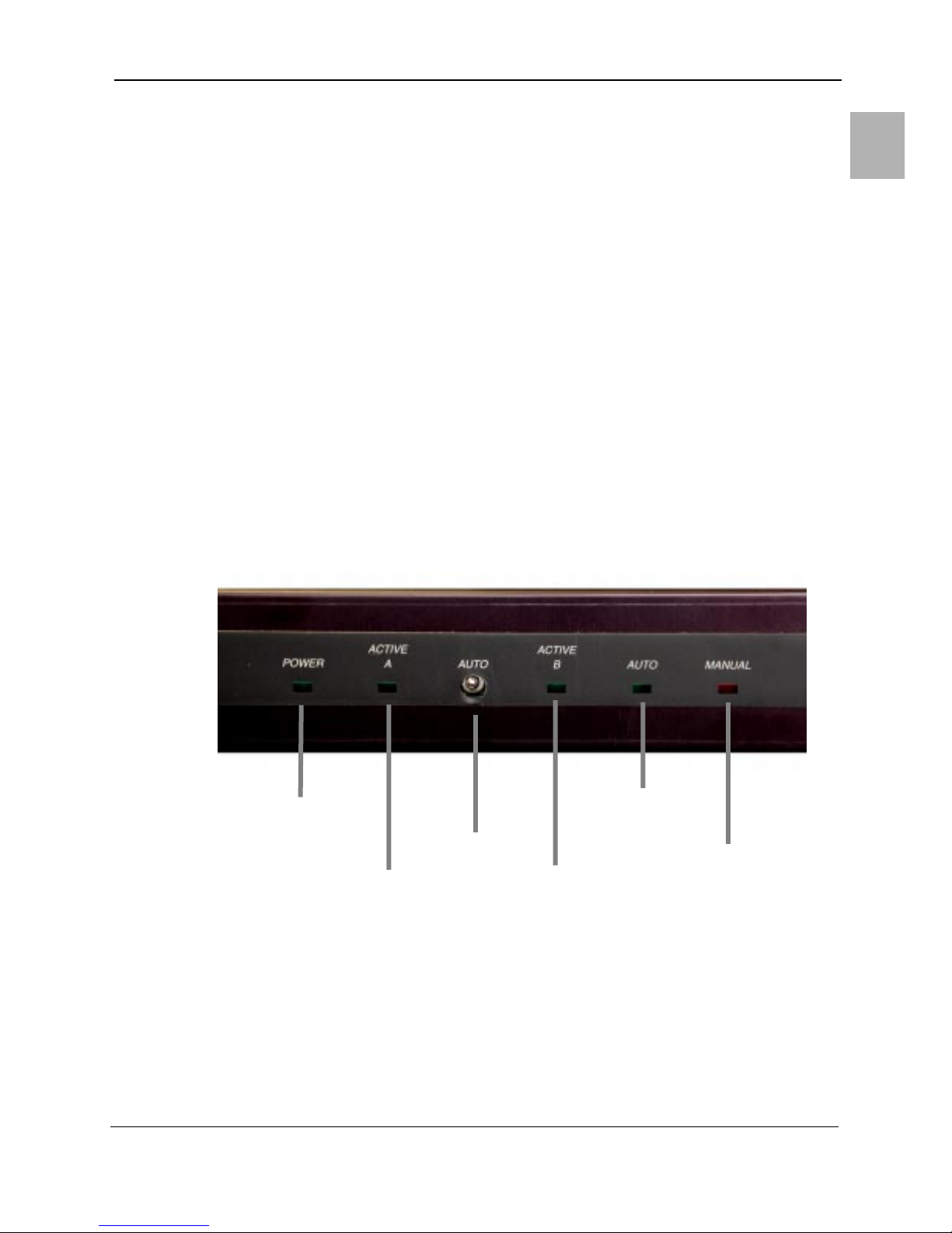
Figure 2-1 DS2 Diversity Switch Front Panel
dB range based on –40 mv per dB ex: –39 DBM + –1.56 VDC
1-2
IF Diversity Switch Operator’s Guide 400462-1 Rev. A
Page 13
Trouble–shooting
1.8 Trouble–shooting
System Overview
The power lamp must be on. If not check the prime power and F1. F1 in located inside the
unit on the PC board. The fuse is a 1/2 amp standard blow type 3 AGC. The normal current
for the DS–2 is less than 125 ma. Lamps other than the power indicator are under processor
control.
Operate the mode switch. If the manual lamp comes on, the processor is probably operating
correctly. If the manual lamp selects the receiver properly, the problem is either AGC
voltage not in the range of –.72 V to –3.4 V or a failure in the U2, U11, U12 IF switch
section or in the associated driver U% or ISO1, ISO2. If an output is defective, the
associated amplifier is suspect. If no action is obtained with the front panel switch, remove
the prime power and try again. Insure the AGC voltage is in the correct range.
Verify the power supply levels are as stated +/– .25 V. The level at the input of U3 for a
particular analog value should be the same as at P1 with the difference in absolute value no
more than 25 mv. If the absolute voltage difference is greater, the associated op amp is
suspect.
The IF switch bandwidth is wide enough that any source greater than 5 MHz can be used
to check general levels. Unused ports should be terminated in 50 ohms to provide proper
return loss.
Failure of the status circuit can be isolated to either the driver U5 of the individual relay.
The processor U3 is a programmed part and is socket mounted. The oscillator can be
checked by monitoring R11 with an oscilloscope. The reset line at pin 2 must be above 3
V to let the processor run.
Figure 2-2 Front Panel Controls and Indicators
1
POWER
INDICATOR
IF Diversity Switch Operator’s Guide 400462-1 Rev. A
ACTIVE
CHANNEL
A
MODE
SWITCH
ACTIVE
CHANNEL
B
AUTO MODE
INDICATOR
MANAUL
MODE
INDICATOR
1-3
Page 14
System Overview
1.9 Specifications
1.9.1 Electrical
Range of AGC input (DAR/FLH)......0.0 to –5.0 V 10 ua
Range of AGC input (TwinStream)..0.0 to +5.0 V 10 ua
Power Supply ........................–20 to –32 VDC (125 ma)
–38 to –52 VDC (125 ma)
Input Range J1, J2 ...... 70 MHz –5 to +5 DBM 50 ohms
Isolation...............................60 dB minimum at 70 MHz
Gain...............................................................0 +/– 2 dB
Return Loss..........................................................26 DB
Switching time .......................less than 3 microseconds
Interface................................25 pin D connector (male)
BNC jack for IF connection
PROM (FLH/DAR).......................................DS2V4.MIK
PROM (TwinStream).................................DS2V4T.MIK
1.9.2 Pin Assignments (P1)
Table 2-2 Pin Assignments - Connector P1
Pin Description
1 Chassis ground, Power com (+)
2 –V in #1 (either –24 V or –48 V depending on model)
3 –V in #2
4 AGC1 input Receiver “A”
5 AGC2 input Receiver “B”
6 AGC Common (+)
7 Remote Select “A” (requires closure to pin 9)
8 Remote Select “B”
9 Remote Common (GND)
10 Receive “A” Status (NO) (10 VA max., 100 v/.1 amp)
11 Receive “B” Status (NO)
12 Manual Mode Status (NC)
13 Status Common
14–25 No connection
Specifications
Note:
Connections to P1 should be with shielded twisted pairs in areas with
high levels of RFI such as TV stations, FM broadcasting stations or
radar.
1.9.3 Mechanical
Size.................................................19" w 8.5" d 1.75" h
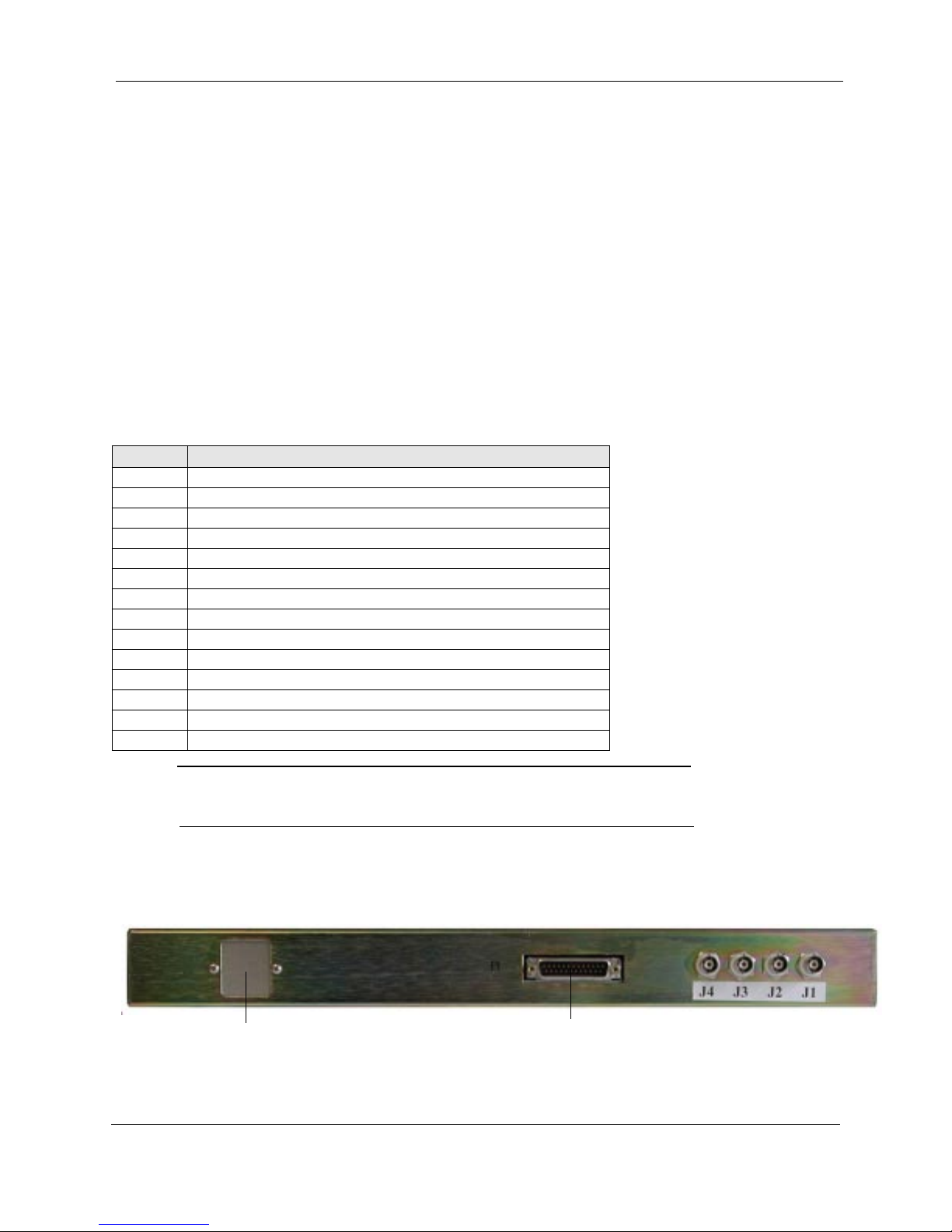
Figure 2-3 DS2 Diversity Switch Rear Panel
AC or DC POWER RECEPTACLE
1-4
P1
IF Diversity Switch Operator’s Guide 400462-1 Rev. A
Page 15

Specifications
System Overview
Table 2-3 Parts List
Item Qty Ref. Des. Description Part No. MFG
1 3 R8,R15,R21 24.9*RES. 24.9+/-1% 1/4W NA55-24R9F CORNING
2 Not Used
3 2 R13,R17 50, RES. POT. 50 1 TURN 3329H-1-500 BOURNS
4 1 R23 100RES. 100+/-5% 1/4W 5043CX100R0 MEPCO
5 4 R16,R24,R32,R33 150, RES. 150+/-5% 1/4W 5043CX150R0 MEPCO
6 2 R4,R5 220, RES. 220+/-5% 1/4W 5043CX220R0 MEPCO
7 1 R29 237*, RES. 237+/-1% 1/4W NA55-237R0F CORNING
8 2 R14, 270 1/2W, RES. 270+/-
5%.1/2W
9 1 R12 330, RES. 330+/-5% 1/4W 5043CX330R0 MEPCO
10 1 R22 715*, RES. 715+/-1% 1/4W NA55-715R0F CORNING
11 1 R3 4.7K, RES. 4.7K+/-5% 1/4W 5043CX4K700 MEPCO
12 6 R1,R2,R6,R7,R27,R28 10K, RES. 10K+/-5% 1/4W 5043CX10K00 MEPCO
13 2 R10,R9 1.0K, RES. 1K+/-5% 1/4W 5043CX100K00 MEPCO
14 1 R11 47K, RES. 47K+/-5% 1/4 W 5043CX47K00 MEPCO
15 2 R25,R26 100K, RES. 100K+/-5% 1/4W 5043CX100K00 MEPCO
16 4 R19,R20,R30,R31 100K*, RES. 100K+/-1% 1/4W NA55-1003F CORNING
17 1 RN1 10KSIP, RES. NET 7X10K EXB-F8E103G PANASONIC
18 3 C2,C6, 3.3-18PF, CAP,VAR. 3-18PF GKU18000,Spraque GOODMAN
19 4 C7,C8,C10,C12 1000PF, CAP. .01+/-10% CER ECQ-V1H102JZ PANASONIC
20 7 C1,C3,C4,C5,C11,C14,C150.1, CAP. .1UF+/-10% CER CK05BX104K AVX
7043CX270R0 MEPCO
1
21 1 C13 1/35V, CAP. 1UF+/-10% 35V 199D105X9035 SPRAGUE
22 1 Q1 2N4403, TRANS. SW. PNP 2N4403 GE
23 1 U1 CM1232, IC, UP MONITOR 1232 CMD/DALLA
S
24 2 ISO1,ISO2 H11A-5100, OPTO ISOLATOR TIL113/4N35 MOT/TI
25 1 U3 MC68705R3CP, IC,
MICROCOMP
26 1 U7 LM317L IC, POS. ADJ VOLT
27 2 U8,U9 LM358A, IC, DUAL OP AMP LM358N NATIONAL
28 1 U5 ULN-2003A, IC, SINK DRVR MC1413P MOT
29 2 U4,U6 MSA-0304, IC, GAIN BLOCK
12DB
30 3 U2,U11,U12 MSWA-2-20, SWITCH,GAAS,
2GHZ
31 2 D9,D10 1N4003, DIODE, SIL 1AMP 1N4003 GI
32 2 D5,D6 1N4735A, DIODE, ZENER
6.2V
33 4 D1,D3,D4,D7 550-2207, LED GREEN 2V 550-2207 DIALIGHT
34 1 D8 550-2407, LED RED, 2V 550-2407 DIALIGHT
35 1 SW1 7103SY9ABE, SW SPTD RT
TOG
36 1 U10 PKC2131PI, DC-DC CONV. PKC2131PI ERICSSON
MC68705R3CP MOT
MOT
REG LM317LZ
MSA-0304 HP
MSWA-2-20 MINI-
CIRCUITS
1N4735A MOT
7103SY9ABE C&K (DK-
CKN1051)
IF Diversity Switch Operator’s Guide 400462-1 Rev. A
1-5
Page 16

System Overview
Specifications
Item Qty Ref. Des. Description Part No. MFG
1 3 R8,R15,R21 24.9*RES. 24.9+/-1% 1/4W NA55-24R9F CORNING
37 6 B-1,B+1,A-1,A+1,B,A 090, Terminal, .090 dia. 0-209-2-01 CONCORD
38 4 J1,J2,J3,J4 31-5431, BNC CONN. PANEL 31-5431 AMPHENOL
39 1 D2 1N755A, DIODE, ZENER 5.1V 1N755A/1N5236 MOT
40 1 F1 1/2A, FUSE, 1/2 SLOBLO 313.500 LITTLEFUSE
41 1 J5 PLUG AC MALE, ENTRY
MODULE
42 3 K1,K2,K3 HE721C0500, SPDT,5V DIP HE721C0500 HAMLIN
43 1 P1 747238-4, CON, PLUG,25POS 747238-4 ÅÅÅÅAMP
44 1 CHASSIS, RACK MNT. DON ENGR
45 4 SPACER, #4X1/2 AL KEYSTONE
46 4 SCREW, 5/16 FH,PHIL
47 1 FRONT PANEL
48 2 MOUNTING EAR
49 1 ADHESIVE LABEL
50 1 ICO-406-S8A-T SOCKET, 40
PIN DIP
51 1 ICO-163-S8A-T SOCKET, 16
PIN DIP
52 3 ICO-083-S8A-T SOCKET, 8
PIN DIP
53 2 FUSE CLIP
54 2 SCREW LOCK, FEM.
55 1 BLANK PCB, DS2 122896-02 REV. B POPE
56 4 NUT, HEX, 31-5652 93F7516 NEWARK
4302.0001 SCHURTER
1-6
IF Diversity Switch Operator’s Guide 400462-1 Rev. A
Page 17
ig
re
2
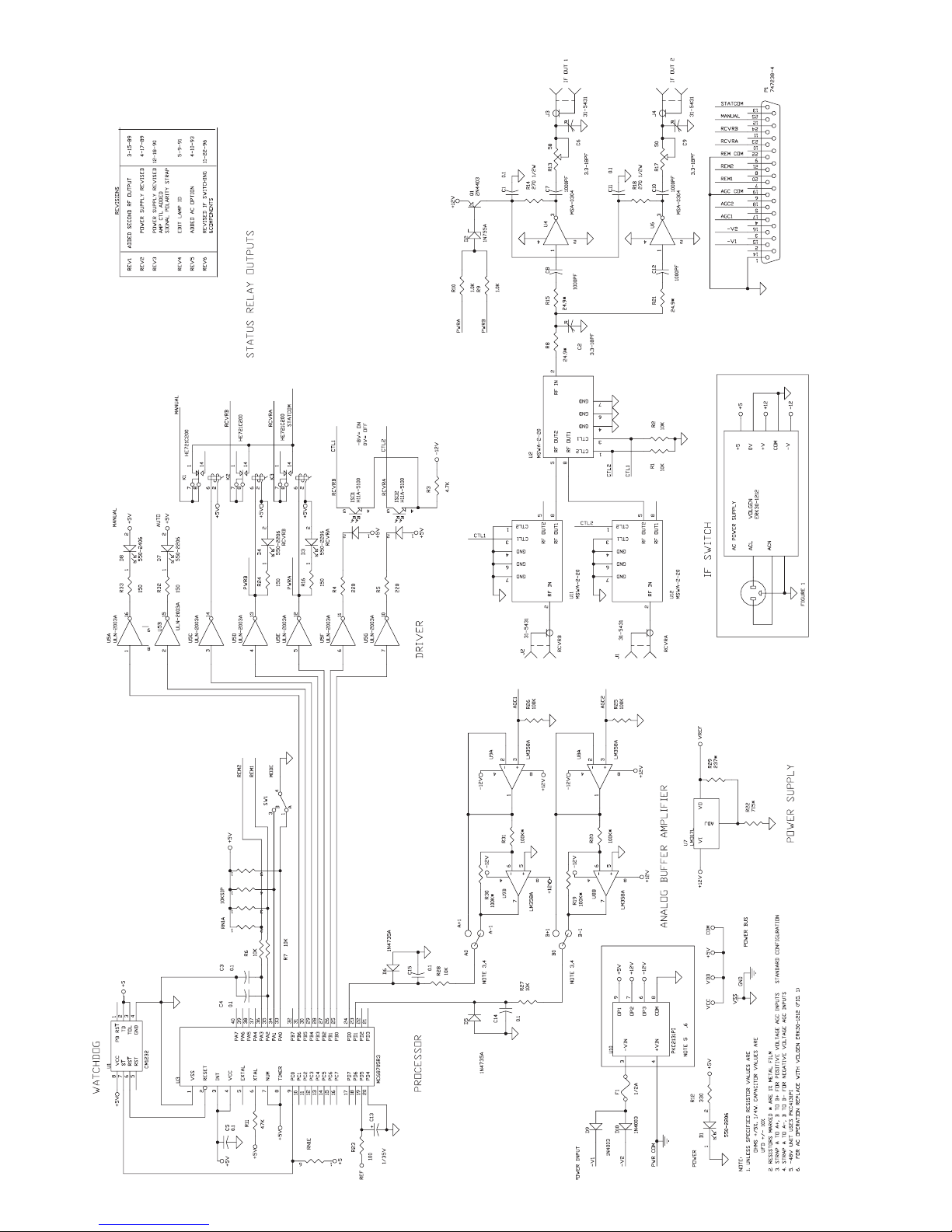
4 Schematic
MICROWAVE RADIO COMMUNICATIONS
DS-2 IF DIVERSITY SWITCH
DWG# DS-2 / REV. 6 / SHEET 1 OF 1 / 9/11/99
-
u
Page 18

System Overview
Specifications
1-8
IF Diversity Switch Operator’s Guide 400462-1 Rev. A
Page 19

Section
2 System Installation
This section explains how to install the DS-2 IF Diversity Switch. The following topics are
covered:
• Unpacking and Handling
• Installation Prerequisites
• Rack Installation
2.1 Unpacking and Handling
Each unit is shipped assembled, wired, and factory tested. Each unit is packaged in
appropriate shipping containers. Care should be taken when removing equipment from the
container to prevent damage to the unit. Check that all parts and accessories are removed
from the container and packing material before they are discarded. Verify that the
equipment items shipped agree with those listed on the sales order.
2
Note:
2.1.1 Inspection
Inspect the equipment for any shipping damage. Check that the equipment is clean and that
no cables or connectors are broken, damaged, or loose.
Note:
2.1.2 Damage in Shipment
Should any damage be discovered after unpacking the unit, use the following procedure:
1. Immediately file a claim with the shipping carrier.
2. Forward a copy of the damage report to Microwave Radio Communications.
3. Contact Customer Service at which time they will determine the disposition of the
equipment.
For Customer Service information, see the Preface section of this manual.
DO NOT discard the container or any packing material until the
mechanical inspection has been satisfactorily completed. This
material must be available in the event that a damage claim needs to
be filed with the shipping carrier.
At the time of inspection, DO NOT make any adjustments to internal
controls or adjustments. The equipment has been factory adjusted for
proper operation prior to shipment.
DS-2 IF Diversity Switch Operator’s
400462-1
Rev. A
2-1
Page 20

System Installation
Installation Prerequisites
2.2 Installation Prerequisites
Complying with installation prerequisites prevents problems from arising during
installation or future maintenance of the unit. Use the following guidelines:
1. Where possible, provide easy access to the front and rear of the equipment rack
(Figure 2-1).
- Allow a minimum of 18 inches clearance at the rear of the equipment rack.
- To service and maintain the equipment, allow a minimum of 36 inches of
clearance in front of the equipment rack.
2. Avoid direct heat to the unit. If unavoidable, use deflector plates or install the unit in
a climate controlled environment.
3. Locate the equipment to allow for an adequate number of AC power outlets for test
equipment and power tools.
4. Check that the rack mounts are sufficiently rigid to support the rack and equipment.
5. Eliminate any conditions that could cause water to drip onto the equipment and
penetrate waveguide or cable openings. Example: leaking roofs, cracks in walls, or
condensation from cold water pipes.
Figure 2-1 Rack Clearances – Top View
REAR
DS2
IF DIVERSITY
FRONT
18"
CLEARANCE
STANDARD
19" RACK
36"
CLEARANCE
2-2
DS-2 IF Diversity Switch Operator’s Guide 400462-1 Rev. A
DS2_SP
Page 21

Rack Installation
2.2.1 Grounding the Equipment Rack
System Installation
The equipment rack must be connected to the station ground using a #6 copper wire or
equivalent. The ground wire should be routed in as straight and direct a route as is practical.
Caution:
Grounding the equipment rack is mandatory.
2.3 Rack Installation
The unit mounts within a standard 19 inch equipment rack. The unit occupies a height of 1
rack units (1RU). The unit attaches to the equipment rack using four 12–24 mounting
screws. See Figure 2-2 for the correct mounting hole locations.
Figure 2-2 Rack Installation
MOUNTING SCREWS
DS2
IF DIVERSITY SWITCH
2
For detailed information on assembling and installing a standard equipment rack, see
Section 2.4, Equipment Rack Installation on page 2-4.
DS-2 IF Diversity Switch Operator’s 400462-1 Rev. A
2-3
Page 22
System Installation
Equipment Rack Installation
2.4 Equipment Rack Installation
Step 1 Remo ve the top and sides of the shipping container and packaging material, free
the rack from the pallet by removing the nuts and bolts securing it in place. Refer
to Table 2-1 for equipment rack specifications.
Table 2-1 Equipment Rack Specifications
Component Description
Finish Black baked enamel
Uprights Channel 3.0” (76.20 mm) deep x 1.4” (34.825 mm) wide x 0.25” (6.35
mm) thick.
Base Angles 4.0” (100.016 mm) high x 6.5” (162.40 mm) deep x 0.38” (9.50
mm) thick.
Top 1” (25.40 mm) high x 0.38” (9.50 mm) thick.
Step 2
Remove the rack from its crate by lifting it off the mounting bolts and place it near
its final mounting location. After the rack has been raised to a vertical position,
remove the shipping support brackets the rack side rails.
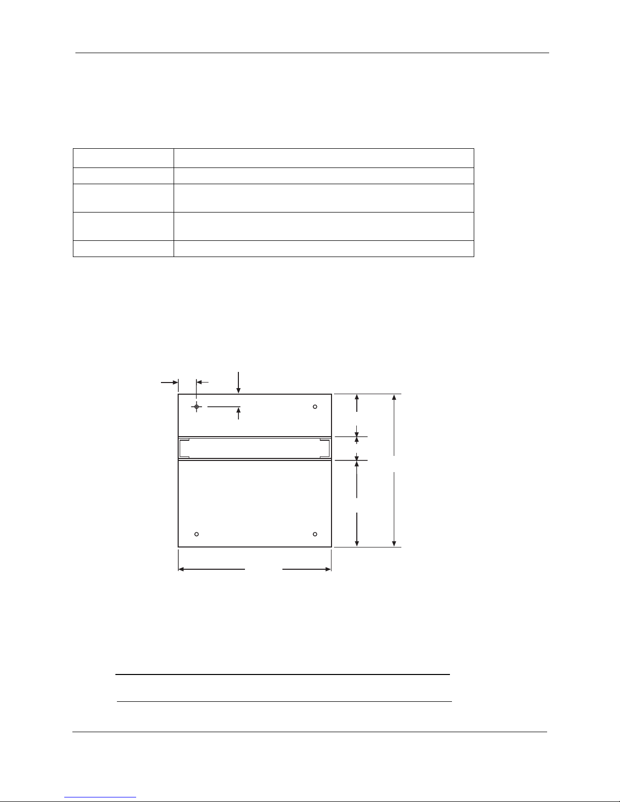
Step 3 A template can be used for marking the floor location drilling holes for anchoring
the hardware (Figure 2-3). Howev er , if the rack is av ailable when these holes are
drilled, it is recommended that the rack base itself be used as a template.
Figure 2-3 Equipment Rack Template
1.25"
2.125"
6.00"
3.00"
21.00"
12.00"
Step 4
Hole size is determined by the type of anchor to be used. On concrete floors, use
the following hardware:
- Bolts: 3/8”, 16 x 2.
- Washers: 3/8”, Lock and flat (1 each per bolt).
- Anchors: 3/8” 16 x 2.
- Caulking Anchors:, “Diamond” type 03060,
Note:
2-4
These anchors require 3/4” holes. On wood floors, use 3/8” x 1 - 1/2”
lag bolts with lock and flat washers.
DS-2 IF Diversity Switch Operator’s Guide 400462-1 Rev. A
20.25"
RACK_TEM
Page 23

Equipment Rack Installation
Step 5 Secure the rack to the adjacent racks and existing superstructure where
applicable. Fasten the rack’s top braces to the superstructure using J-bolts.
If there is not an existing superstructure, the top of the rack should be braced to a ceiling or
wall.
Figure 2-4 Equipment Rack – Front View
MOUNTING
HOLES
System Installation
2
RACK_FR
84.00"
DS-2 IF Diversity Switch Operator’s 400462-1 Rev. A
2-5
Page 24

System Installation
Equipment Rack Installation
2-6
DS-2 IF Diversity Switch Operator’s Guide 400462-1 Rev. A
 Loading...