

Page 1

Microwave Data Systems
MDS FIVE Series
Software Defined IDU™
User Interface Manual
Document Number: 05-4574A01, Rev. C
Date: 14 August 2006
Page 2

Page 3

© 2006 Microwave Data Systems Inc. All Rights Reserved.
This book and the information contained herein is the proprietary and confidential information of
Microwave Data Systems Inc. that is provided by Microwave Data Systems™ exclusively for evaluating the
purchase of Microwave Data Systems Inc. technology and is protected by copyright and trade secret laws.
No part of this document may be disclosed, reproduced, or transmitted in any form or by any means,
electronic or mechanical, for any purpose without the express written permission of Microwave Data
Systems Inc., 175 Science Pkwy, Rochester, NY 14620.
For permissions, contact Microwave Data Systems Inc. Marketing Group at 1-585-241-5510 or 1-585-2428369 (FAX).
Notice of Disclaimer
The information and specifications provided in this document are subject to change without notice.
Microwave Data Systems Inc. reserves the right to make changes in design or components as progress in
engineering and manufacturing may warrant.
The Warranty(s) that accompany Microwave Data Systems Inc. products are set forth in the sales
agreement/contract between Microwave Data Systems Inc. and its customer. Please consult the sales
agreement for the terms and conditions of the Warranty(s) proved by Microwave Data Systems Inc. To
obtain a copy of the Warranty(s), contact you Microwave Data Systems Inc. Sales Representative at 1585-241-5510 or 1-585-242-8369 (FAX).
The information provided in this Microwave Data Systems Inc., document is provided “as is” without
warranty of any kind, either expressed or implied, including, but not limited to, the implied warranties of
merchantability, fitness for a particular purpose, or non-infringement. Some jurisdictions do not allow the
exclusion of implied warranties, so the above exclusion may not apply to you.
In no event shall Microwave Data Systems Inc. be liable for any damages whatsoever – including special,
indirect, consequential or incidental damages or damages for loss of profits, revenue, use, or data whether
brought in contract or tort, arising out of or connected with any Microwave Data Systems Inc., document or
the use, reliance upon or performance of any material contained in or accessed from this Microwave Data
Systems Inc. document. Microwave Data Systems’s license agreement may be provided upon request.
Additional Terms and Conditions will be finalized upon negotiation or a purchase.
The above information shall not be constructed to imply any additional warranties for Microwave Data
Systems Inc. equipment including, but not limited to, warranties of merchantability or fitness for an
intended use.
Trademark Information
Software Defined Indoor Unit™ (SDIDU™) is a product and trademark of CarrierComm, Inc.
Java™ is a trademark of Sun Microsystems, Inc.
Windows® is a registered trademark of Microsoft Corporation
All other brand or product names are trademarks or registered trademarks of their respective companies or
organizations.
Part Number: 05-4574A01
Page 4

1-2
User Interface Manual
MDS FIVE Series
05-4574A01, Rev. C
© Copyright 2006 Microwave Data Systems Inc. All Rights Reserved
Page 5

Table of Contents
1 Introduction
1.1 Overview . . . . . . . . . . . . . . . . . . . . . . . . . . . . . . . . . . . . . . . . . . . . . . . . . . . 1-1
1.2 Modes of User Interfaces . . . . . . . . . . . . . . . . . . . . . . . . . . . . . . . . . . . . . . 1-1
1.3 Features Overview . . . . . . . . . . . . . . . . . . . . . . . . . . . . . . . . . . . . . . . . . . . 1-1
1.4 Security Measures . . . . . . . . . . . . . . . . . . . . . . . . . . . . . . . . . . . . . . . . . . . 1-2
2 Getting Started
2.1 NMS Station Configuration . . . . . . . . . . . . . . . . . . . . . . . . . . . . . . . . . . . . . 2-1
2.1.1 System Requirements . . . . . . . . . . . . . . . . . . . . . . . . . . . . . . . . . . 2-1
2.1.2 PC Network Configuration. . . . . . . . . . . . . . . . . . . . . . . . . . . . . . . 2-2
2.1.3 Web browser . . . . . . . . . . . . . . . . . . . . . . . . . . . . . . . . . . . . . . . . . 2-2
2.1.4 Telnet/SSH client. . . . . . . . . . . . . . . . . . . . . . . . . . . . . . . . . . . . . . 2-3
2.1.5 SNMP . . . . . . . . . . . . . . . . . . . . . . . . . . . . . . . . . . . . . . . . . . . . . . 2-3
2.1.6 HyperTerminal. . . . . . . . . . . . . . . . . . . . . . . . . . . . . . . . . . . . . . . . 2-3
2.2 Access rights for users . . . . . . . . . . . . . . . . . . . . . . . . . . . . . . . . . . . . . . . . 2-3
2.2.1 User Level 1 – Monitor . . . . . . . . . . . . . . . . . . . . . . . . . . . . . . . . . 2-3
2.2.2 User Level 2 – Operator . . . . . . . . . . . . . . . . . . . . . . . . . . . . . . . . 2-4
2.2.3 User Level 3 – Administrator . . . . . . . . . . . . . . . . . . . . . . . . . . . . . 2-4
3 User Interface
3.1 Overview . . . . . . . . . . . . . . . . . . . . . . . . . . . . . . . . . . . . . . . . . . . . . . . . . . . 3-1
3.1.1 WEB Overview . . . . . . . . . . . . . . . . . . . . . . . . . . . . . . . . . . . . . . . 3-1
3.1.2 CLI Overview. . . . . . . . . . . . . . . . . . . . . . . . . . . . . . . . . . . . . . . . . 3-2
3.1.3 SNMP Overview . . . . . . . . . . . . . . . . . . . . . . . . . . . . . . . . . . . . . . 3-5
3.2 Navigation Tree. . . . . . . . . . . . . . . . . . . . . . . . . . . . . . . . . . . . . . . . . . . . . . 3-7
3.3 UI Screens . . . . . . . . . . . . . . . . . . . . . . . . . . . . . . . . . . . . . . . . . . . . . . . . . 3-9
3.3.1 Starting Information . . . . . . . . . . . . . . . . . . . . . . . . . . . . . . . . . . . 3-10
3.3.2 Status Panel . . . . . . . . . . . . . . . . . . . . . . . . . . . . . . . . . . . . . . . . 3-11
3.3.3 General Network Configuration . . . . . . . . . . . . . . . . . . . . . . . . . . 3-12
3.3.4 SNMP Configuration . . . . . . . . . . . . . . . . . . . . . . . . . . . . . . . . . . 3-14
3.3.5 Syslog Configuration . . . . . . . . . . . . . . . . . . . . . . . . . . . . . . . . . . 3-16
3.3.6 E-mail Configuration . . . . . . . . . . . . . . . . . . . . . . . . . . . . . . . . . . 3-18
3.3.7 STP Data Configuration . . . . . . . . . . . . . . . . . . . . . . . . . . . . . . . 3-20
3.3.8 STP NMS Configuration . . . . . . . . . . . . . . . . . . . . . . . . . . . . . . . 3-21
3.3.9 Serial Configuration. . . . . . . . . . . . . . . . . . . . . . . . . . . . . . . . . . . 3-23
3.3.10 Device Information . . . . . . . . . . . . . . . . . . . . . . . . . . . . . . . . . . 3-24
3.3.11 Device Names . . . . . . . . . . . . . . . . . . . . . . . . . . . . . . . . . . . . . . 3-25
3.3.12 Set Date and Time . . . . . . . . . . . . . . . . . . . . . . . . . . . . . . . . . . 3-27
3.3.13 Serial Number Information . . . . . . . . . . . . . . . . . . . . . . . . . . . . 3-29
3.3.14 Security Configuration. . . . . . . . . . . . . . . . . . . . . . . . . . . . . . . . 3-30
3.3.15 Reprogramming CPU . . . . . . . . . . . . . . . . . . . . . . . . . . . . . . . . 3-32
3.3.16 WEB Configuration . . . . . . . . . . . . . . . . . . . . . . . . . . . . . . . . . . 3-32
3.3.17 Add User Entry . . . . . . . . . . . . . . . . . . . . . . . . . . . . . . . . . . . . . 3-34
3.3.18 Delete / Edit User Entry. . . . . . . . . . . . . . . . . . . . . . . . . . . . . . . 3-36
Page 6

3.3.19 View Event Log . . . . . . . . . . . . . . . . . . . . . . . . . . . . . . . . . . . . . 3-38
3.3.20 Restore System Defaults. . . . . . . . . . . . . . . . . . . . . . . . . . . . . . 3-39
3.3.21 System Reboot . . . . . . . . . . . . . . . . . . . . . . . . . . . . . . . . . . . . . 3-40
3.3.22 E1 / T1 Channel Map . . . . . . . . . . . . . . . . . . . . . . . . . . . . . . . . 3-41
3.3.23 E1 / T1 Ports . . . . . . . . . . . . . . . . . . . . . . . . . . . . . . . . . . . . . . . 3-43
3.3.24 Voice Codec . . . . . . . . . . . . . . . . . . . . . . . . . . . . . . . . . . . . . . . 3-47
3.3.25 STM1/OC3 Channel Map . . . . . . . . . . . . . . . . . . . . . . . . . . . . . 3-49
3.3.26 STM1/OC3 Ports. . . . . . . . . . . . . . . . . . . . . . . . . . . . . . . . . . . . 3-50
3.3.27 Authorization . . . . . . . . . . . . . . . . . . . . . . . . . . . . . . . . . . . . . . . 3-52
3.3.28 Configuration Summary. . . . . . . . . . . . . . . . . . . . . . . . . . . . . . . 3-54
3.3.29 Tx Mute Configuration . . . . . . . . . . . . . . . . . . . . . . . . . . . . . . . . 3-55
3.3.30 APC Configuration. . . . . . . . . . . . . . . . . . . . . . . . . . . . . . . . . . . 3-56
3.3.31 Protection Configuration . . . . . . . . . . . . . . . . . . . . . . . . . . . . . . 3-58
3.3.32 Link Configuration Wizard . . . . . . . . . . . . . . . . . . . . . . . . . . . . . 3-59
3.3.33 ODU Power . . . . . . . . . . . . . . . . . . . . . . . . . . . . . . . . . . . . . . . . 3-62
3.3.34 ODU Channel wizard. . . . . . . . . . . . . . . . . . . . . . . . . . . . . . . . . 3-63
3.3.35 ODU Configuration . . . . . . . . . . . . . . . . . . . . . . . . . . . . . . . . . . 3-66
3.3.36 Alarm Threshold . . . . . . . . . . . . . . . . . . . . . . . . . . . . . . . . . . . . 3-68
3.3.37 Alarm Configuration. . . . . . . . . . . . . . . . . . . . . . . . . . . . . . . . . . 3-70
3.3.38 Alarm History. . . . . . . . . . . . . . . . . . . . . . . . . . . . . . . . . . . . . . . 3-72
3.3.39 Active Alarms . . . . . . . . . . . . . . . . . . . . . . . . . . . . . . . . . . . . . . 3-73
3.3.40 Graphs. . . . . . . . . . . . . . . . . . . . . . . . . . . . . . . . . . . . . . . . . . . . 3-74
3.3.41 Statistics – Data Switch. . . . . . . . . . . . . . . . . . . . . . . . . . . . . . . 3-77
3.3.42 Statistics – NMS Switch . . . . . . . . . . . . . . . . . . . . . . . . . . . . . . 3-79
3.3.43 WEB Configuration . . . . . . . . . . . . . . . . . . . . . . . . . . . . . . . . . . 3-80
3.3.44 CLI Configuration . . . . . . . . . . . . . . . . . . . . . . . . . . . . . . . . . . . 3-80
3.3.45 SNMP Configuration . . . . . . . . . . . . . . . . . . . . . . . . . . . . . . . . . 3-80
3.3.46 BERT Mode. . . . . . . . . . . . . . . . . . . . . . . . . . . . . . . . . . . . . . . . 3-81
3.3.47 WEB Configuration . . . . . . . . . . . . . . . . . . . . . . . . . . . . . . . . . . 3-82
3.3.48 CW Mode . . . . . . . . . . . . . . . . . . . . . . . . . . . . . . . . . . . . . . . . . 3-83
3.3.49 Loopback. . . . . . . . . . . . . . . . . . . . . . . . . . . . . . . . . . . . . . . . . . 3-84
3.3.50 Modem Temperature. . . . . . . . . . . . . . . . . . . . . . . . . . . . . . . . . 3-85
3.3.51 Logout . . . . . . . . . . . . . . . . . . . . . . . . . . . . . . . . . . . . . . . . . . . . 3-86
4 FTP Upload Procedures
4.1 FTP Upload Procedures . . . . . . . . . . . . . . . . . . . . . . . . . . . . . . . . . . . . . . . 4-1
4.2 Windows FTP Client . . . . . . . . . . . . . . . . . . . . . . . . . . . . . . . . . . . . . . . . . . 4-1
4.3 Graphical FTP Client (IE: Filezilla) . . . . . . . . . . . . . . . . . . . . . . . . . . . . . . . 4-1
5 Troubleshooting
5.1 Cannot access SDIDU™ using IP (Web / Telnet / SSH) . . . . . . . . . . . . . . 5-1
5.2 The web page resolution is improper . . . . . . . . . . . . . . . . . . . . . . . . . . . . . 5-1
5.3 Unable to establish a secure connection . . . . . . . . . . . . . . . . . . . . . . . . . . 5-1
5.4 Unable to access different network services. . . . . . . . . . . . . . . . . . . . . . . . 5-1
5.5 Hardware Reset to Factory Defaults. . . . . . . . . . . . . . . . . . . . . . . . . . . . . . 5-2
6 Appendix
6.1 Abbreviations & Acronyms . . . . . . . . . . . . . . . . . . . . . . . . . . . . . . . . . . . . . 6-1
6.2 References and Links . . . . . . . . . . . . . . . . . . . . . . . . . . . . . . . . . . . . . . . . . 6-2
Page 7

User Interface Manual
6.2.1 Install Mozilla Firefox. . . . . . . . . . . . . . . . . . . . . . . . . . . . . . . . . . . 6-2
6.2.2 Install Internet Explorer . . . . . . . . . . . . . . . . . . . . . . . . . . . . . . . . . 6-2
6.2.3 Install Java . . . . . . . . . . . . . . . . . . . . . . . . . . . . . . . . . . . . . . . . . . 6-2
6.2.4 Install PuTTY. . . . . . . . . . . . . . . . . . . . . . . . . . . . . . . . . . . . . . . . . 6-2
6.3 Alarm Descriptions . . . . . . . . . . . . . . . . . . . . . . . . . . . . . . . . . . . . . . . . . . . 6-3
1-3
© Copyright 2006 Microwave Data Systems Inc. All Rights Reserved
MDS FIVE Series
05-4574A01, Rev. C
Page 8

1-4
User Interface Manual
MDS FIVE Series
05-4574A01, Rev. C
© Copyright 2006 Microwave Data Systems Inc. All Rights Reserved
Page 9

1 Introduction
1.1 Overview
The User Interface Manual explains the different user interfaces for accessing and
configuring the SDIDU™.
1.2 Modes of User Interfaces
The terminal can be accessed through Serial, Ethernet, or Modem interfaces
using the following modes:
Web Interface (Normal / SSL)
Command Line Interface, CLI (Serial Console/Telnet/SSH)
SNMP Agent
1.3 Features Overview
SDIDU™ Provisioning
Network Time Protocol (NTP) client
Spanning-Tree Protocol (STP) configuration
SNMP configuration
Serial port configuration
Security configuration
Feature authorization
Configuration saving/retrieving
Alarm notification configuration
DHCP client for automated NMS network configuration
Link Provisioning
Modulation, Bandwidth, E1/T1 channels, Ethernet, STM-1/OC-3
Status and Monitoring
Automated alarm reporting
SNR, RSL, Errored-Seconds
Event Log
Alarm Log
Remote logging to Syslog server
SNMP TRAPs
Firmware Upgrade
© Copyright 2006 Microwave Data Systems Inc. All Rights Reserved MDS FIVE Series
05-4574A01, Rev. C
Page 10

1-2
User Interface Manual
User Management
1.4 Security Measures
The software allows for partitioning resources and prohibiting access of sensitive
information. The design of the software also prevents users from intruding on
other users and/or resources on the network. Security measures include:
Encrypted passwords
Multilevel configuration permissions
Network data encryption
Accounting and logging features provide protection from and information
about access attempts.
MDS FIVE Series
05-4574A01, Rev. C
© Copyright 2006 Microwave Data Systems Inc. All Rights Reserved
Page 11

2 Getting Started
2.1 NMS Station Configuration
2.1.1 System Requirements
2.1.1.1 Local
Local connection of a PC to a SDIDU™ can be accomplished via a serial or
network port. The connection requirements are listed below.
2.1.1.1.1 Serial
PC with serial port and DB-9 to HD-15 SDIDU™ cable
Serial communications software (e.g. Hyperterm)
2.1.1.1.2 Network
PC with 10/100 Ethernet interface
CAT 5 patch cable for connecting PC to SDIDU™ NMS port
Web browser, or
Telnet or SSH client, or
SNMP manager
2.1.1.2 Remote
Remote connection from a PC to a SDIDU™ can be accomplished via a serial
communication connection or an internet connection. The connection
requirements are listed below.
2.1.1.2.1 Network
PC with network connection
Remote SDIDU™ with rootable IP address
Web browser, or
Telnet or SSH client, or
SNMP manager
© Copyright 2006 Microwave Data Systems Inc. All Rights Reserved MDS FIVE Series
05-4574A01, Rev. C
Page 12
2-2
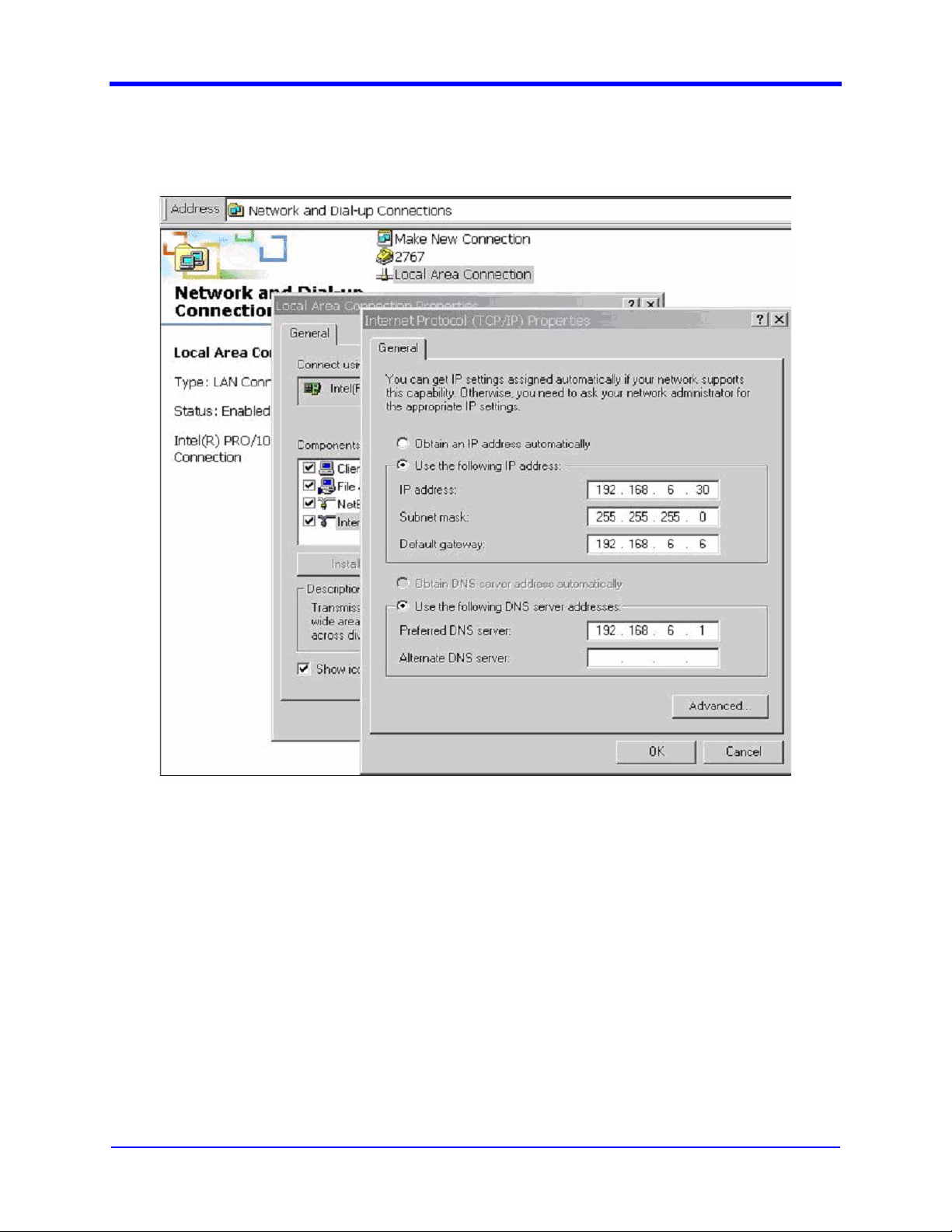
2.1.2 PC Network Configuration
User Interface Manual
To set up a network connection:
Access the TCP/IP properties from the control panel network connection
menu as shown in Figure 2-1. Verify the IP address, net mask, gateway,
and DNS server settings.
Execute a ping to verify connectivity, by typing “ping” followed by the target
SDIDU™ IP address at a command prompt.
2.1.3 Web browser
When accessing the software via the web interface, use one of the following web
browsers:
MDS FIVE Series
05-4574A01, Rev. C
Figure 2-1. Network connections.
© Copyright 2006 Microwave Data Systems Inc. All Rights Reserved
Page 13

User Interface Manual
Use Internet Explorer version 5.5 or above
Mozilla Firefox (latest version preferred)
Use the browser’s default settings. Refer to Section 6.2.1 and Section 6.2.2 for
intructions for obtaining a web browser.
The web interface also requires the use of Sun Java JVM version 1.2.2 or above.
Refer to Section 6.2.3 for intructions for obtaining Sun Java JVM.
2.1.4 Telnet/SSH client
When accessing the software via the CLI interface, use a telnet or SSH client. An
SSH client is similar to a telnet client except it accesses the target over a secure
connection.
Windows provides a Windows Standard telnet client that may be accessed
through the command prompt. An alternate telnet client may be used.
Refer to Section 6.2.4 for downloading PuTTY, a popular Telnet / SSH Client for
Windows.
2-3
2.1.5 SNMP
Configure SNMP manager for accessing the Target (Connected Product).
2.1.6 HyperTerminal
When connecting via a HyperTerminal program, use the following settings:
BaudRate=38400
Parity=none
DataBit=8
StopBit=1
The settings may be reconfigured based on system requirements.
2.2 Access rights for users
The system has five user access levels for configuring and viewing data through
the user interface. User accounts can be added and deleted for different access
levels. The five user levels and their corresponding user rights are described
below.
2.2.1 User Level 1 – Monitor
User has minimum access rights and can only view the following pages:
© Copyright 2006 Microwave Data Systems Inc. All Rights Reserved
MDS FIVE Series
05-4574A01, Rev. C
Page 14

2-4
Home
General Device Information,
Configuration Summary
Active Alarm Status
Alarm History
All Graphs
2.2.2 User Level 2 – Operator
User has all the access rights of User Level 1 and has additional rights to edit
following pages:
Reboot,
All Radio Link and Data Link Configuration pages
Alarm Configuration page
BERT page
User Interface Manual
2.2.3 User Level 3 – Administrator
User has all the rights of User Level 2 and has additional rights to the following
pages:
All Network Configuration
Serial and Security configuration
All Device Information pages
All Maintenance and Restore Defaults pages
STP Screens
MDS FIVE Series
05-4574A01, Rev. C
© Copyright 2006 Microwave Data Systems Inc. All Rights Reserved
Page 15
3 User Interface
3.1 Overview
3.1.1 WEB Overview
The web interface is a feature-filled graphical interface for configuring and
monitoring the terminal. Access to web interface is provided via a web browser
and a normal or secure connection.
To access the web interface:
1. Open a web browser (browser requirements are discussed in Section
2.1.3).
2. Type the IP address of the SDIDU™ in the address bar and press GO.
3. A popup window will prompt for a user name and password.
4. Enter a user name and password then press OK.
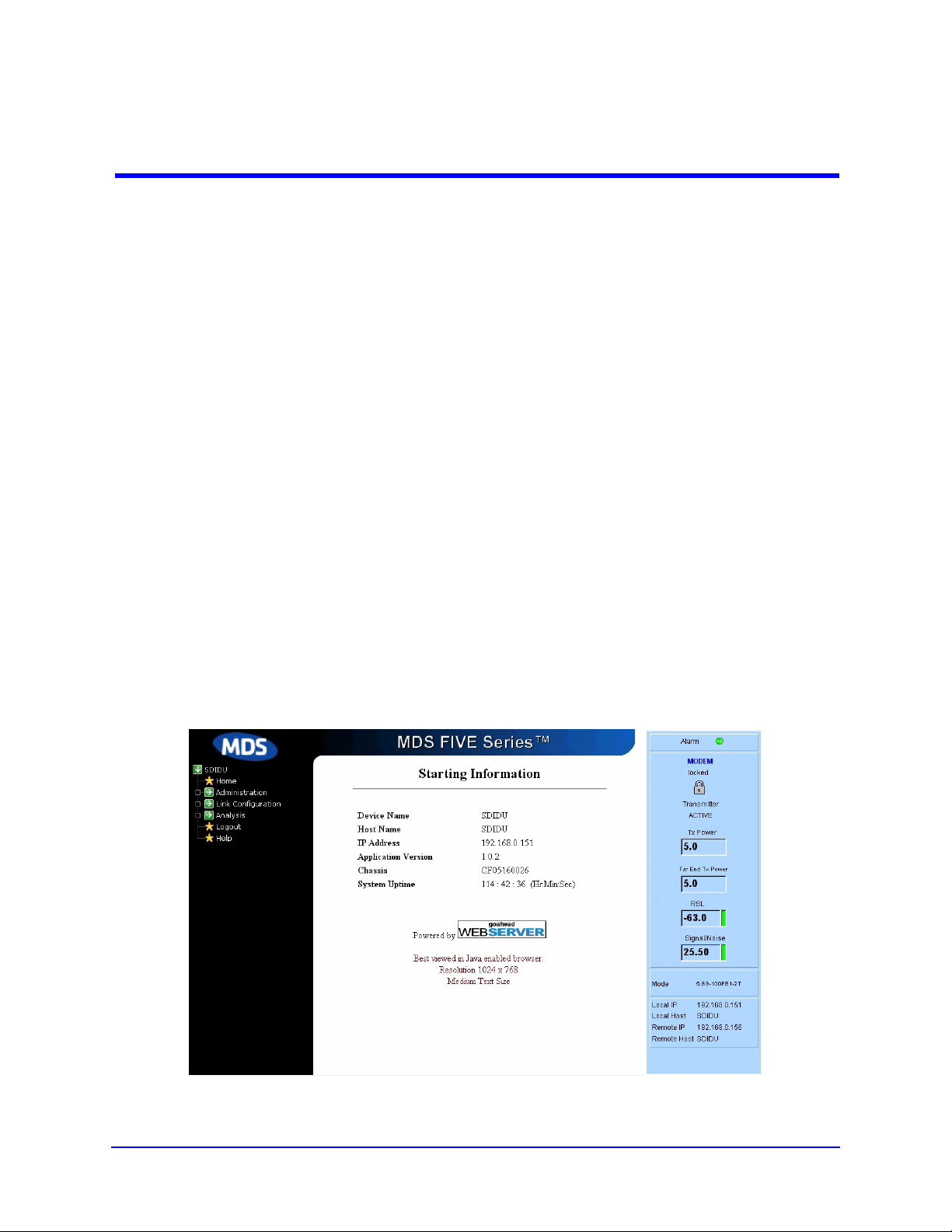
5. Upon successful authentication, the Starting Information Screen (Figure 3-
1) is displayed.
Figure 3-1. Web starting information screen.
© Copyright 2006 Microwave Data Systems Inc. All Rights Reserved MDS FIVE Series
05-4574A01, Rev. C
Page 16

3-2
3.1.2 CLI Overview
The CLI provides a text based interface for configuring and monitoring the
terminal. The CLI is accessed by doing one of the following:
Using Ethernet interface,
1. Telnet / SSH to the terminal (using IP address of the terminal).
2. Enter a user name and password at the login prompt.
Using Serial interface,
1. Establish an RS232 connection using a serial terminal.
2. Enter a user name and password at the login prompt.
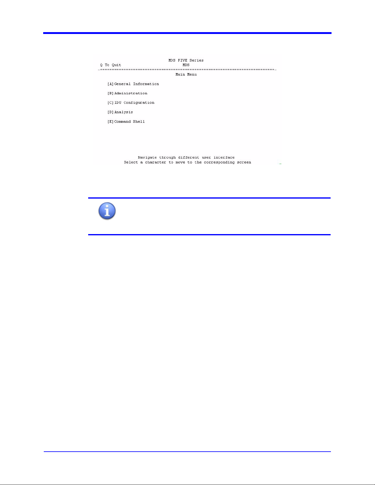
Upon successful authentication the ”General Information Screen” is displayed
(Figure 3-2). Switch to the “Main Menu” screen by pressing the M-key. From the
“Main Menu,” the user can navigate through various interface screens.
User Interface Manual
Figure 3-2. CLI starting information screen.
3.1.2.1 How to use CLI screens
3.1.2.1.1 Menu Screens
Menu screens are used to navigate between functions. They display a list of
navigation choices. Each choice is listed with a character encased within [ ]
braces, or “hotkey.” Press the “hotkey” to switch to the corresponding screen. For
example, in Figure 3-3, enter ‘a’ / ‘A’, to switch to the “General Information” screen
(the “General Information” screen is displayed in Figure 3-2).
MDS FIVE Series
05-4574A01, Rev. C
© Copyright 2006 Microwave Data Systems Inc. All Rights Reserved
Page 17
User Interface Manual
3-3
Figure 3-3. CLI menu type screens.
Further references to “hotkey” in this document will refer to the
character encapsulated in [ ] brackets for the individual parameter.
Note
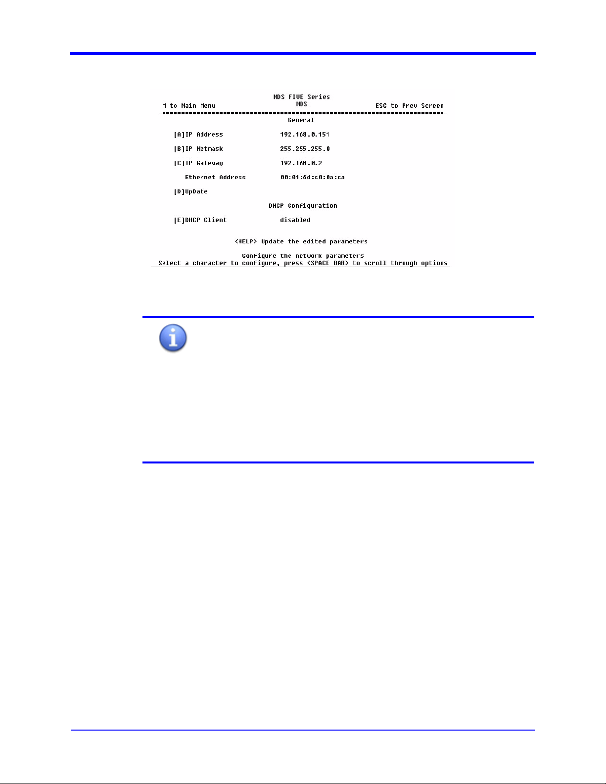
3.1.2.2 Configurable Screens
Configurable screens are used to set various parameters. Figure 3-4 shows the
“General Network Configuration” screen, which is an example of a configurable
screen. Parameters are listed with their values and a “hotkey.” Press the “hotkey”
to configure the corresponding parameter. For example, enter ‘a’ / ‘A’, to edit IP
address, then press “Enter Key”. Some parameters may have a set list of values.
For example, the DHCP Client parameter has two values: Enabled and Disable.
To edit this type of parameter, press the corresponding “hotkey” (in this case “E”),
then press the “Space Bar”-key, to scroll through different values. Once the
desired value is displayed, press the “Enter”-key. If the parameter is displayed
without a “hotkey,” it indicates a read-only parameter.
© Copyright 2006 Microwave Data Systems Inc. All Rights Reserved
MDS FIVE Series
05-4574A01, Rev. C
Page 18
3-4
User Interface Manual
Figure 3-4. Configurable Screen.
All the CLI screens will have the following messages:
Note
Navigation Message: Help message about possible navigation
from the screen. This will be displayed at top left and top right of
the screen.
Screen Message: Help message about the screen. This will be
displayed at 24
th
row.
Access Message: Help message about how to access
parameters of the screen. This will be displayed at 25
th
(last) row
MDS FIVE Series
05-4574A01, Rev. C
© Copyright 2006 Microwave Data Systems Inc. All Rights Reserved
Page 19

User Interface Manual
3-5
In the CLI, there are two different types of parameter updates.
Some parameters are updated individually and others are
updated as a group.
Warning
To perform an Individual Update:
1. Edit the parameter value.
2. Press the “Enter”-key.
3. If update was successful, the message “Updated
Successfully” will be displayed.
4. If the update failed, a failure message will be displayed.
To perform a Group Update:
1. Edit the parameter value.
2. Press the “Enter”-key.
3. Press the character specified for “Update.”
4. If the update was successful, the message “Updated
Successfully” will be displayed.
5. If the update failed, a failure message will be displayed.
1. CLI screens should ideally be viewed at 25 rows by 80
Warning
2. A window of less than 25x80 will have incomplete
3.1.3 SNMP Overview
The SNMP agent interface provides a means of configuring the terminal using
Simple Network Management Protocol (SNMP) commands.
3.1.3.1 MIBs
A Managed Information Base (MIB) file describes a type of device in a network as
a data structure. The SDIDU™ SNMP agent supports the following MIBs.
ccm_reg.mib: This MIB file contains the registration for Microwave Data
Systems enterprise OID and sub trees for Microwave Data Systems
products.
ccm_SDIDU.mib: This is the main MIB file for the SDIDU™ product.
ccm_SDIDU_v1Traps.mib: SDIDU™ product version 1 trap MIB file
columns (25 x 80).
content.
© Copyright 2006 Microwave Data Systems Inc. All Rights Reserved
MDS FIVE Series
05-4574A01, Rev. C
Page 20

3-6
ccm_SDIDU_v2Traps.mib: SDIDU™ product version 2 trap MIB file
The SNMP agent interface uses these MIB files to configure the system.
3.1.3.2 SNMP Agent Parameters
The SNMP agent interface configurable parameters are described in the following
sections..
WEB and CLI interfaces can be used to configure the SNMP
parameters below. Change in any of the parameters below
Note
If the agent is configured in “v3 only” or “v1-v2-v3” mode, SNMPv3 “admin” user
can configure the SNMP users. There are 4 possible levels of users. User levels
are same as described in Section 2.2.
The SNMP agent does not support level based access if the agent is configured
as “v1 only” or “v2 only” mode. In the case of v1 and v2 modes of operation,
Level1 access is given to the read operation and Level4 access is given for the
write operation. Thus, in v1 and v2 modes of operation, the user has full access to
system configurations if a valid write community string is used.
reconfigures the agent
User Interface Manual
.
3.1.3.2.1 SNMP Mode
The SNMP agent can be configured to operate in any of the following modes:
disable
v1 only
v2 only
v3 only
v1-v2-v3
If the agent is configured to run as v1 only, v2 only or v3 only, then the user can
access the agent only using SNMP v1, v2 or v3 respectively.
If the agent is configured to operate in the v1-v2-v3 mode, then the user can
access the agent using SNMP v1, v2 or v3.
The SNMP agent is disabled by selecting the disable mode.
Note
SNMP v1 and v2 provides a weak security by using the
community strings. The user can always configure the SNMP
agent to operate in “v3 only” mode, which uses authentication as
well as encryption for secure transaction.
MDS FIVE Series
05-4574A01, Rev. C
© Copyright 2006 Microwave Data Systems Inc. All Rights Reserved
Page 21

User Interface Manual
3.1.3.2.2 Trap Version
A trap is an SNMP message issued by an SNMP agent that reports an event.
The Trap Version parameter configures the SNMP trap version. The SNMP agent
uses the specified version to send the traps to configured trap managers.
3.1.3.2.3 Auth Trap Enable
If enabled, SNMP agent generates Authentication failure trap on authentication
failure in any request.
3.1.3.2.4 Read Community
A community string is an SNMP security password. The Read Community string is
used in read operation of SNMP v1 or v2, and allows the SNMP manager to issue
Get and GetNext messages.
3.1.3.2.5 Write Community
3-7
The Write Community string is used in write operation of SNMP v1 or v2, and
allows the SNMP Manager to issue Set messages.
3.1.3.2.6 Trap community
The Trap Community string allows the SNMP agent to issue Trap messages.
3.1.3.2.7 SNMP Auth Password
The SNMP Auth Password is used in only SNMP v3 mode of operation and is the
authorization password for the “admin” user.
3.1.3.2.8 SNMP Priv Password
The SNMP Priv Password is used in only SNMP v3 mode of operation and is the
privacy password for the “admin” user.
3.1.3.2.9 Trap Manager
Trap Manager configures the trap manager’s IP addresses. A maximum of four
Trap managers can be configured. The SNMP agent sends the traps to all the
configured trap managers.
3.2 Navigation Tree
The Navigation tree shown describes the location of each user interface screen.
Nested screens are indented under the screen from which they can be accessed.
j Home
© Copyright 2006 Microwave Data Systems Inc. All Rights Reserved
MDS FIVE Series
05-4574A01, Rev. C
Page 22

3-8
User Interface Manual
c Starting Information
c Status Panel
j Navigation Tree
c Administration
n Network Configuration
n General Network configuration
n SNMP Configuration
n Syslog Configuration
n E-mail Configuration
n STP Data Configuration
n STP NMS Configuration
n Serial Configuration
n Security Configuration
n Device Configuration
n Device Information
n Device Names
n Set Date and Time
n Serial Number Information
n Maintenance
n Reprogramming CPU
n Add User
n Delete User/ Edit User Entry
n View Event Log
n Restore Default
n Reboot
c Link Configuration
n Authorization
n Configuration Summary
n Data Link
n E1 / T1 Channel Map
n E1 / T1 Ports
n Voice Codec
n STM-1/OC3 Channel Map (Consult factory for availability)
n STM-1/OC3 Ports (Consult factory for availability)
n Radio Link
n APC Configuration
n Protection Configuration
n ODU TX Mute Configuration
n Link Configuration
n ODU Power
n ODU Channel
n ODU Configuration
c Analysis
n Alarms
4 Alarm Threshold
4 Alarm Configuration
4 Alarm History
4 Active Alarms
n Graphs
MDS FIVE Series
05-4574A01, Rev. C
© Copyright 2006 Microwave Data Systems Inc. All Rights Reserved
Page 23

User Interface Manual
3.3 UI Screens
Each UI Screen is described in the following sections. Each screen section
contains the following components:
3-9
4 RSL
4 Signal/Noise
4 Tx Power
4 Error Seconds
4 Equalizer Taps
4 Constellation
4 Mux/Demux
4 Temperature
n Statistics
4 Data Switch
4 NMS Switch
n BERT Mode
n CW Mode
n Loopback
c Logout
User Access Level - Each screen is labeled with “User Access Level:
Level X,” where X refers access rights for a particular user.
Description – Gives a description of the screen and the parameters it
displays/edits.
Web Configuration – Gives details to access parameters through web
browser.
CLI Configuration – Gives details to access parameters through CLI Telnet
/ SSH session / Hyper terminal.
SNMP Configuration – Gives details to access parameters through SNMP
manager
Read-only pages are the only exception, as they have no specific details for
different interfaces.
© Copyright 2006 Microwave Data Systems Inc. All Rights Reserved
MDS FIVE Series
05-4574A01, Rev. C
Page 24
3-10
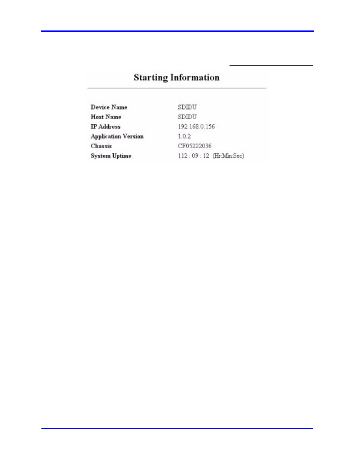
3.3.1 Starting Information
Figure 3-5. Starting Information.
User Interface Manual
User Access Level: Level 1
3.3.1.1 Description
Figure 3-5 shows the starting information screen of user interface. This screen
provides general information about the SDIDU™, including:
Device Name – Name of the product
Host Name – Name of the host
IP Address – IP Address of the system.
Application Version – Version information of the application
Chassis Serial Number – Serial number of the product (factory
assigned).
System Uptime – Uptime of the System.
MDS FIVE Series
05-4574A01, Rev. C
© Copyright 2006 Microwave Data Systems Inc. All Rights Reserved
Page 25
User Interface Manual
3.3.2 Status Panel
3-11
User Access Level: Level 1
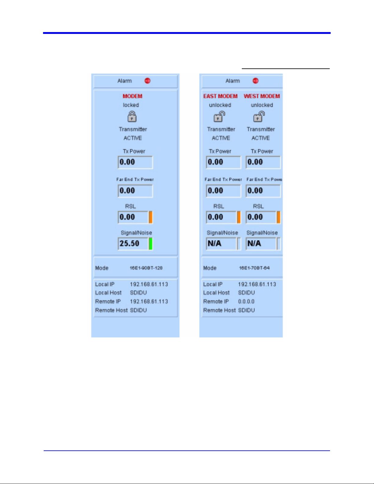
Figure 3-6. Status Panel.
3.3.2.1 Description
Figure 3-6 shows the status panel for 1 + 0 and 1 + 1 configurations. This screen
provides the modem and alarm status of the terminal as follows:
1. ALARM – Alarm Status
Red LED indicates an alarm has occurred
Green LED indicates no alarms in the terminal
© Copyright 2006 Microwave Data Systems Inc. All Rights Reserved
MDS FIVE Series
05-4574A01, Rev. C
Page 26
3-12
Click on the LED to view the “Active Alarms” Page.
2. East / West MODEM – MODEM Status
NA indicates MODEM is inactive
LOCK Symbol indicates MODEM is locked
UNLOCK Symbol indicates MODEM is unlocked
3. TX Power – Transmitting power of the ODU in dB.
4. Far End TX Power – Transmitting power of the link partner ODU in dB.
5. SDIDU RSL – RSL value in dBm.
6. SIGNAL/NOISE – Signal/Noise value in dB. If Modem is unlocked, this
value will not be displayed.
7. East mode – Operation mode of the East Link
8. West mode – Operation mode of the West Link
9. Local IDU Information – IP Address and Host Name
10. Remote IDU Information – IP Address and Host Name
3.3.3 General Network Configuration
User Interface Manual
User Access Level: Level 3
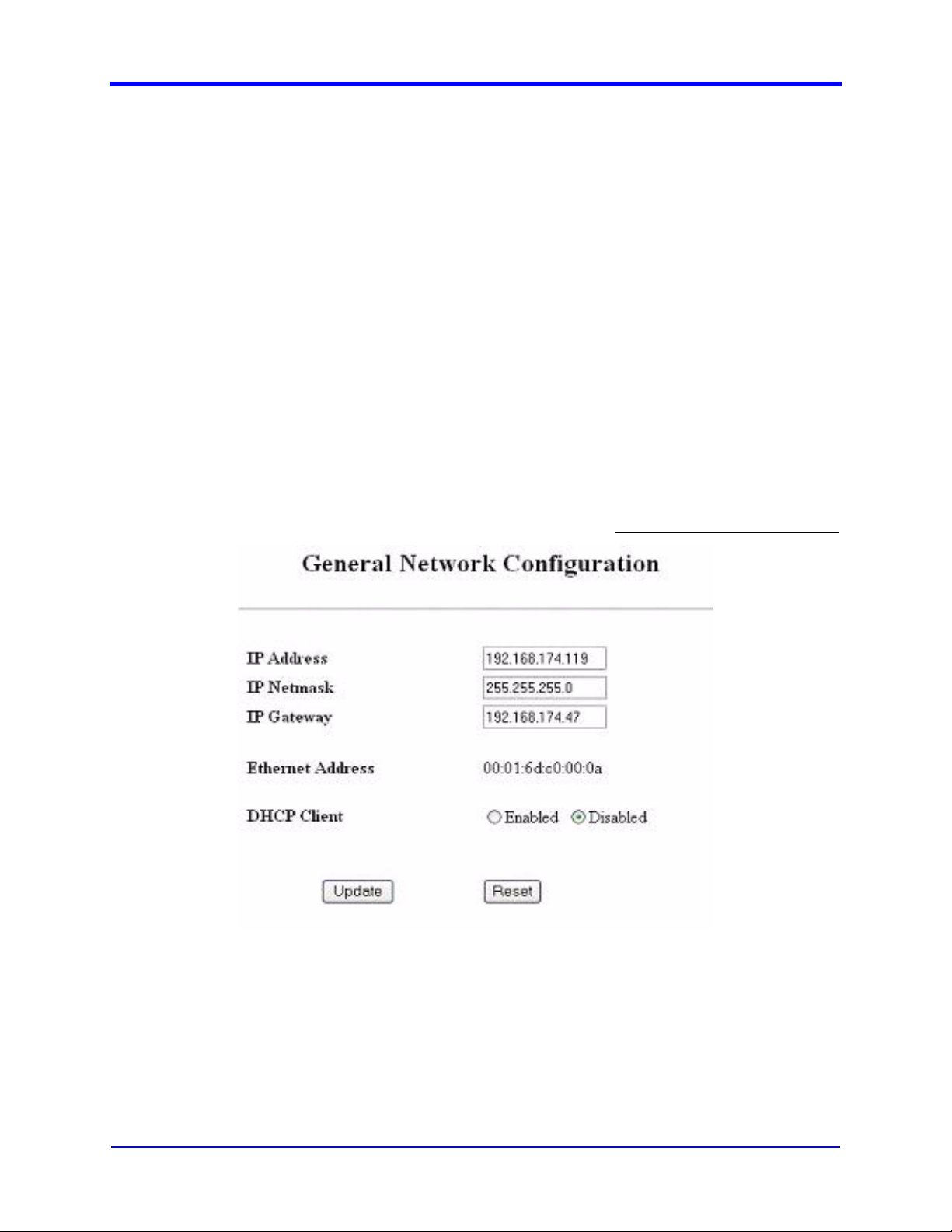
Figure 3-7. General Network Configuration.
3.3.3.1 Description
The General Network Configuration screen (Figure 3-7) is used to configure the
following general network related parameters:
MDS FIVE Series
05-4574A01, Rev. C
© Copyright 2006 Microwave Data Systems Inc. All Rights Reserved
Page 27

User Interface Manual
1. IP Address - Enter the IP Address for the terminal. If unsure contact your
network administrator.
2. IP Netmask – Enter the appropriate netmask depending on the class of
the network. If unsure contact your network administrator.
3. IP Gateway – Enter the gateway IP Address for your subnet. If unsure
contact your network administrator.
4. Ethernet Address – MAC or Hardware address of the terminal.
5. DHCP Client – When enabled, network parameters are obtained
dynamically from a DHCP server. The other parameters on the page
cannot be modified when DHCP is enabled.
3.3.3.2 WEB Configuration
1. Navigate to AdministrationÆNetwork Configuration and click on the
General Menu in the left panel.
2. All General Network related parameters are displayed with current/present
values.
3. To revert to previous values, press Reset button.
4. To change parameters, enter new values and press the “update” button.
5. The page is refreshed and displayed with the updated or current/present
values.
6. If parameters are not updated with the entered values, the values entered
may be invalid for that parameter.
3-13
3.3.3.3 CLI Configuration
1. Navigate to AdministrationÆGeneral Network MenuÆ Network
Configuration.
2. All General Network related parameters are displayed with current/present
values.
3. To edit an individual parameter, enter its hotkey, edit its value and press
the Enter key.
4. To revert to the previous value, press the “Esc” key while editing the value.
5. When editing the DHCP Client parameter, scroll through the options using
the Space Bar key and press Enter to select an option.
6. To update the edited parameter, press the hotkey for “Update”.
7. The page is refreshed and displayed with the updated or current/present
values.
8. If parameters are not updated with entered values, the value entered may
be invalid for that parameter.
3.3.3.4 SNMP Configuration
1. Select a parameter from the MIB section ccmSDIDUSysCfgNetworkIP.
© Copyright 2006 Microwave Data Systems Inc. All Rights Reserved
MDS FIVE Series
05-4574A01, Rev. C
Page 28
3-14
2. Use the SNMP GET command to get the value of the required parameter.
3. Use the SNMP SET command to set the value of the required parameter.
4. The SNMP agent will return the actual value upon successful set or get
operation. Upon failure, the SNMP agent will return an error if the value set
is out of range, or the agent is not able to get or set the value, or the user
does not have access rights to the selected parameter.
3.3.4 SNMP Configuration
User Interface Manual
User Access Level: Level 3
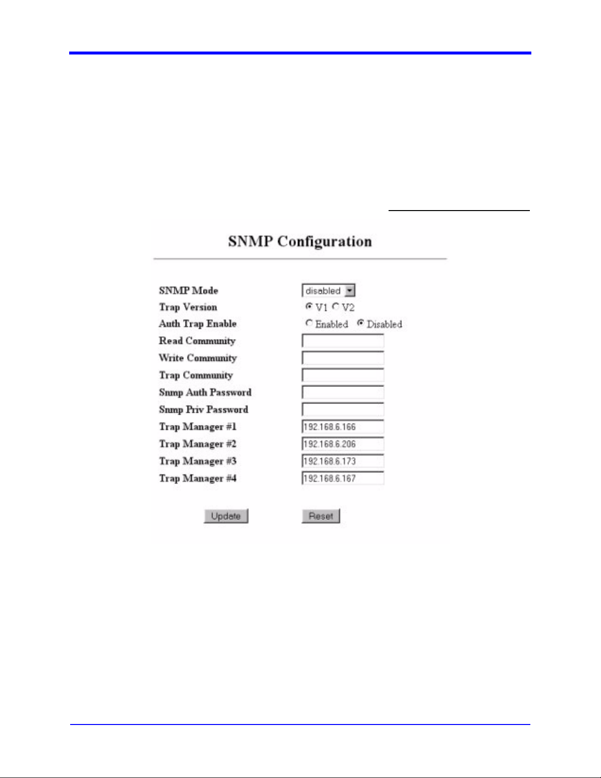
3.3.4.1 Description
Figure 3-8 shows the screen used to configure the following SNMP related
parameters:
1. SNMP Mode – The mode in which SNMP Agent is currently configured.
2. Trap Version – The Trap Version in which SNMP Agent is currently
configured .
MDS FIVE Series
05-4574A01, Rev. C
Figure 3-8. SNMP Configuration.
© Copyright 2006 Microwave Data Systems Inc. All Rights Reserved
Page 29

User Interface Manual
3. Auth Trap Enable – Enable/Disable sending of authorization traps to
SNMP manager.
4. Read Community - Community String used while reading data from the
SNMP Agent in SNMP V1/V2 mode.
5. Write Community - Community String used while writing data to the
SNMP Agent in SNMP V1/V2 mode.
6. Trap Community - Community String used while sending traps from the
SNMP Agent.
7. SNMP Auth Password - Password required for authorization while
reading or writing data in SNMP V3 Mode.
8. SNMP Priv Password - Privacy password required while reading or
writing data in SNMP V3 Mode.
9. Trap Manager #1 - #4 - IP Addresses of the Trap Managers to which
Traps are to be sent.
3.3.4.2 WEB Configuration
1. Navigate to AdministrationÆNetwork Configuration and click on the SNMP
link in the left panel.
2. All SNMP related parameters are displayed with current/present values.
3. To revert to the previous values, press Reset button.
4. To change the parameters, enter new values and press “update” button.
5. The page will be refreshed and displayed with current/present values.
6. If parameters are not updated with entered values, the values entered may
be invalid.
7. The values of SNMP Auth Password and SNMP Priv Password
parameters will not be displayed because these parameters are treated as
passwords.
8. If no values are entered for the parameters indicated above, the present
values in the system will not be overwritten.
3-15
3.3.4.3 CLI Configuration
1. Navigate to AdministrationÆ General Network MenuÆ SNMP
Configuration.
2. All SNMP related parameters are displayed with current/present values.
3. To edit an individual parameter, enter its hotkey, edit its value and press
the Enter key.
4. To revert to the previous value, press the “Esc” key while editing the value.
5. Scroll through the options for the following parameters using the Space
Bar key and press the Enter key to select among the options.
a. SNMP Mode
b. Trap Version
© Copyright 2006 Microwave Data Systems Inc. All Rights Reserved
MDS FIVE Series
05-4574A01, Rev. C
Page 30
3-16
c. Auth Trap Enable
6. The page is refreshed and displayed with the updated or current/present
values.
7. If parameters are not updated with entered values, the values entered may
be invalid.
3.3.4.4 SNMP Configuration
1. Select a parameter from the MIB section
ccmSDIDUSysCfgNetworkSNMP.
2. Use the SNMP GET command to get the value of the required parameter.
3. Use the SNMP SET command to set the value of the required parameter.
4. The SNMP agent will return the actual value upon successful set or get
operation. Upon failure, the SNMP agent will return an error if the value set
is out of range, or the agent is not able to get or set the value, or the user
does not have access rights to the selected parameter.
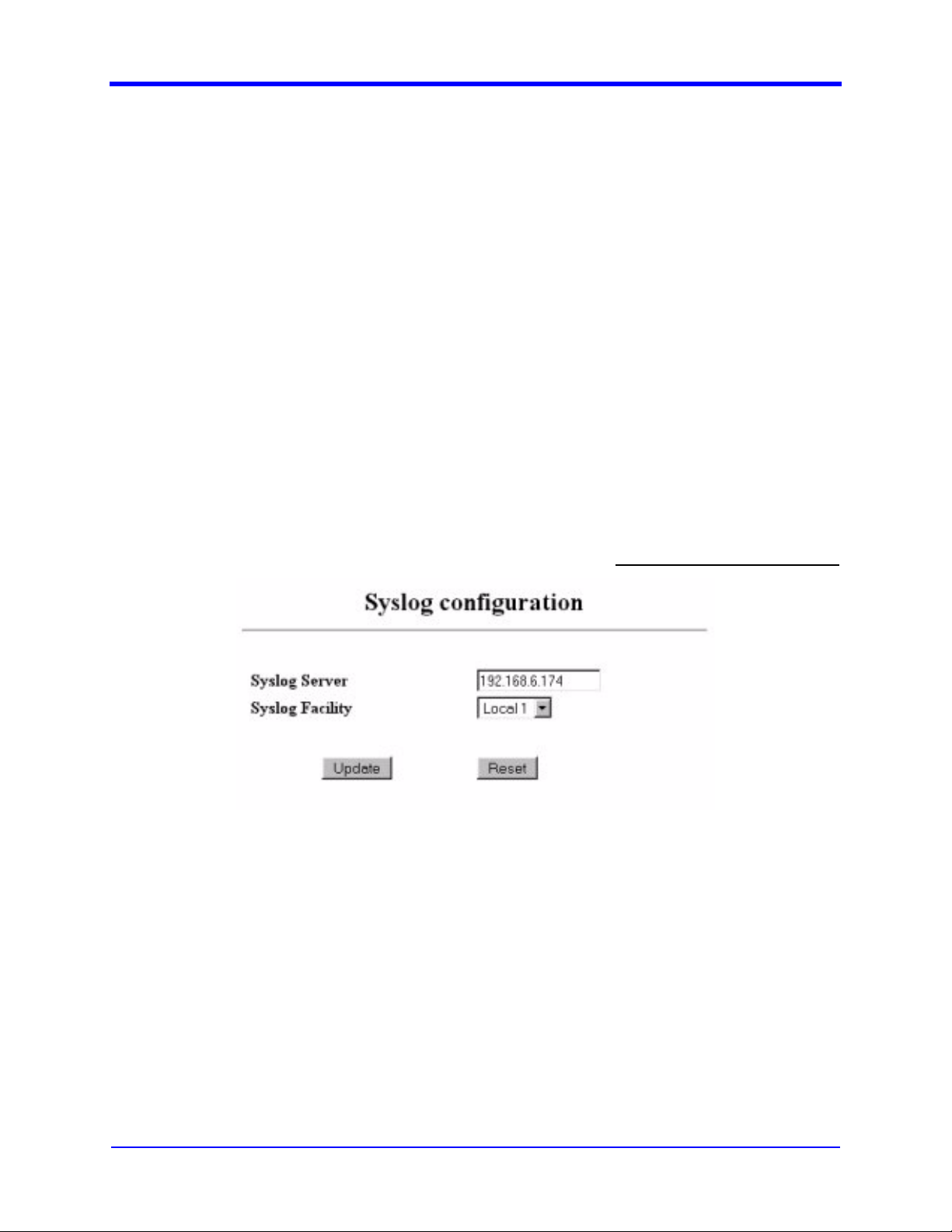
3.3.5 Syslog Configuration
User Interface Manual
Figure 3-9. Syslog Configuration.
3.3.5.1 Description
Figure 3-9 shows the screen used to configure the following Syslog related
parameters:
1. Syslog IP - Enter Syslog IP Address for the system. If unsure contact your
network administrator.
2. Syslog Facility - Select Syslog facility for the system. If unsure contact
your network administrator.
User Access Level: Level 3
MDS FIVE Series
05-4574A01, Rev. C
© Copyright 2006 Microwave Data Systems Inc. All Rights Reserved
Page 31

User Interface Manual
3.3.5.2 WEB Configuration
1. Navigate to AdministrationÆNetwork ConfigurationÆSyslog Configuration
in the left panel.
2. All Syslog related parameters are displayed with current/present values.
3. To revert to previous values, press Reset button.
4. To change parameters, enter new values and press the “update” button.
5. The page is refreshed and displayed with the updated or current/present
values.
6. If parameters are not updated with entered values, the values entered may
be invalid for that parameter.
3.3.5.3 CLI Configuration
1. Navigate to AdministrationÆGeneral Network MenuÆSyslog
Configuration
2. All Syslog related parameters are displayed with current/present values.
3. To edit an individual parameter, enter its hotkey, edit its value and press
the Enter key.
4. To revert to the previous value, press the “Esc” key while editing the value.
5. Scroll through the options for the following parameters using the Space
Bar key and press the Enter key to select among the options.
3-17
a. Syslog facility
6. To update the edited parameter, press the hotkey for “Update”.
7. The page is refreshed and displayed with the updated or current/present
values.
8. If the parameters are not updated with the entered values, the values
entered may be invalid for that parameter.
3.3.5.4 SNMP Configuration
1. Select a parameter from the MIB section
ccmSDIDUSysCfgNetworkSysLog.
2. Use the SNMP GET command to get the value of the required parameter
3. Use the SNMP SET command to set the value of the required parameter
4. The SNMP agent will return the actual value upon successful set or get
operation. Upon failure, the SNMP agent will return an error if the value set
is out of range, or the agent is not able to get or set the value, or the user
does not have access rights to the selected parameter.
© Copyright 2006 Microwave Data Systems Inc. All Rights Reserved
MDS FIVE Series
05-4574A01, Rev. C
Page 32

3-18
3.3.6 E-mail Configuration
User Interface Manual
User Access Level: Level 3
Figure 3-10. E-mail Configuration.
3.3.6.1 Description
The screen in Figure 3-10 is used to configure the following E-mail related
parameters:
1. SMTP Enable – Enable / Disable mail.
2. SMTP Server IP – Enter the SMTP server IP. If unsure, contact your
network administrator.
3. SMTP Port – Enter the SMTP port. Default 25.
4. Username – Enter the user name of your E-mail account.
5. Password – Enter the password of your mail account.
6. E-mail #1 - #3 – Enter the recipients’ mail addresses.
MDS FIVE Series
05-4574A01, Rev. C
© Copyright 2006 Microwave Data Systems Inc. All Rights Reserved
Page 33

User Interface Manual
Username and password should be left blank if the SMTP server
does not require authentication.
Note
3.3.6.2 WEB Configuration
1. Navigate to AdministrationÆNetwork ConfigurationÆE-mail Configuration
in the left panel.
2. All E-mail related parameters are displayed with current/present values.
3. To revert to previous values, press Reset button.
4. To change the parameters, enter new values and press the “update”
button.
5. The page is refreshed and displayed with the updated or current/present
values.
6. If parameters are not updated with entered values, the value entered may
be invalid for that parameter.
3-19
3.3.6.3 CLI Configuration
1. Navigate to AdministrationÆGeneral Network MenuÆE-mail
Configuration.
2. All E-mail related parameters are displayed with current/present values.
3. To edit an individual parameter, enter its hotkey, edit its value and press
the Enter key.
4. To revert to the previous value, press the “Esc” key while editing the value.
5. Scroll through the options for the following parameters using the Space
Bar key and press the Enter key to select among the options.
a. SMTP Enable
6. To update the edited parameter, press the hotkey for “Update”.
7. The page is refreshed and displayed with the updated or current/present
values.
8. If parameters are not updated with entered values, the value entered may
be invalid for that parameter.
3.3.6.4 SNMP Configuration
1. Select a parameter from the MIB section ccmSDIDUSysCfgNetworkEmail.
2. Use the SNMP GET command to get the value of the required parameter.
3. Use the SNMP SET command to set the value of the required parameter.
© Copyright 2006 Microwave Data Systems Inc. All Rights Reserved
MDS FIVE Series
05-4574A01, Rev. C
Page 34

3-20
4. The SNMP agent will return the actual value upon successful set or get
operation. Upon failure, the SNMP agent will return an error if the value set
is out of range, or the agent is not able to get or set the value, or the user
does not have access rights to the selected parameter
Enable the “SMTP Enable parameter” to send e-mail to the
specified addresses upon occurrence of selected alarms.
Note
3.3.7 STP Data Configuration
User Interface Manual
User Access Level: Level 3
Figure 3-11. STP Data Configuration.
3.3.7.1 Description
This screen is used to configure the STP status (enable/disable) and the Bridge
priority (see Figure 3-11).
3.3.7.2 WEB Configuration
1. Navigate to AdministrationÆNetwork ConfigurationÆSTP Data in the left
panel.
2. All STP Data parameters (STP Status and Bridge Priority) are displayed
with current/present values.
3. To revert to previous values, press Reset button.
4. To change the parameters, enter new values and press the “update”
button.
MDS FIVE Series
05-4574A01, Rev. C
© Copyright 2006 Microwave Data Systems Inc. All Rights Reserved
Page 35

User Interface Manual
3.3.7.3 CLI Configuration
1. Navigate to AdministrationÆ Network ConfigurationÆ STP
ConfigurationÆData Switch Configuration.
2. All STP Data parameters (STP Status and Bridge Priority) are displayed
with current/present values.
3. To edit an individual parameter, enter its hotkey, modify its value by
scrolling through the options using the Space Bar key.
4. To revert to the previous value, press the “Esc” key while editing the
value.
5. To update the edited parameter, press the hotkey for “Update”.
6. The page is refreshed and displayed with the updated or current/present
values.
3.3.7.4 SNMP Configuration
1. Select a parameter from the MIB section
ccmSDIDUSysCfgNetworkSTPData.
2. Use the SNMP GET command to get the value of the required parameter.
3. Use the SNMP SET command to set the value of the required parameter.
4. The SNMP agent will return the actual value upon successful set or get
operation. Upon failure, the SNMP agent will return an error if the value set
is out of range, or the agent is not able to get or set the value, or the user
does not have access rights to the selected parameter
3-21
3.3.8 STP NMS Configuration
Figure 3-12. STP NMS Configuration.
User Access Level: Level 3
© Copyright 2006 Microwave Data Systems Inc. All Rights Reserved
MDS FIVE Series
05-4574A01, Rev. C
Page 36

3-22
3.3.8.1 Description
This screen is used to configure STP NMS status (enable/disable) and Bridge
priority. (see Figure 3-12).
3.3.8.2 WEB Configuration
1. Navigate to and click on the AdministrationÆNetwork ConfigurationÆSTP
NMS.
2. All STP NMS parameters (STP Status and Bridge Priority) are displayed
with current/present values.
3. To revert to previous value, press Reset button.
4. To change the parameters, enter new values and press the “update”
button.
3.3.8.3 CLI Configuration
1. Navigate to AdministrationÆ Network ConfigurationÆ STP
ConfigurationÆ NMS Switch Configuration
2. All STP NMS parameters (STP Status and Bridge Priority) are displayed
with current/present values.
3. To edit an individual parameter, enter its hotkey, modify its value by
scrolling through the options using the Space Bar key, and press “Enter”.
4. To revert to the previous value, press the “Esc” key while editing the value.
5. To update the edited parameter, press the hotkey for “Update”.
6. The page is refreshed and displayed with the updated or current/present
values.
User Interface Manual
3.3.8.4 SNMP Configuration
1. Select a parameter from the MIB section
ccmSDIDUSysCfgNetworkSTPNMS
2. Use the SNMP GET command to get the value of the required parameter
3. Use the SNMP SET command to set the value of the required parameter
4. The SNMP agent will return the actual value upon successful set or get
operation. Upon failure, the SNMP agent will return an error if the value set
is out of range, or the agent is not able to get or set the value, or the user
does not have access rights to the selected parameter.
MDS FIVE Series
05-4574A01, Rev. C
© Copyright 2006 Microwave Data Systems Inc. All Rights Reserved
Page 37

User Interface Manual
3.3.9 Serial Configuration
Figure 3-13. Serial Configuration.
3.3.9.1 Description
3-23
User Access Level: Level 3
The screen shown in Figure 3-13 is used to configure the following serial port
related parameters.:
1. Data Baud Rate – Select the suitable baud rate for the selected device.
3.3.9.2 WEB Configuration
1. Navigate to AdministrationÆSerial Configuration in the left panel.
2. All Serial port related parameters are displayed with current/present
values.
3. To revert to previous values, press Reset button.
4. To change the parameters, enter new values and press the “update”
button.
5. The page is refreshed and displayed with the updated or current/present
values.
6. If parameters are not updated with entered values, the value entered may
be invalid for that parameter.
3.3.9.3 CLI Configuration
1. Navigate to AdministrationÆSerial Configuration.
2. All Serial related parameters are displayed with current/present values.
3. To edit an individual parameter, enter its hotkey, edit its value and press
the Enter key.
4. To revert to the previous value, press the “Esc” key while editing the value.
© Copyright 2006 Microwave Data Systems Inc. All Rights Reserved
MDS FIVE Series
05-4574A01, Rev. C
Page 38

3-24
5. Scroll through the options for the following parameters using the Space
Bar key and press the “Enter” key to select among the options.
a. Device Selection
b. Serial Byte Format
c. Data Baud Rate
6. To update the edited parameter, press the hotkey for “Update”.
7. The page is refreshed and displayed with the updated or current/present
values.
8. If parameters are not updated with entered values, the value entered may
be invalid for that parameter.
3.3.9.4 SNMP Configuration
1. Select a parameter from the MIB section ccmSDIDUSysCfgSerial
2. Use the SNMP GET command to get the value of the required parameter
3. Use the SNMP SET command to set the value of the required parameter
4. The SNMP agent will return the actual value upon successful set or get
operation. Upon failure, the SNMP agent will return an error if the value set
is out of range, or the agent is not able to get or set the value, or the user
does not have access rights to the selected parameter
User Interface Manual
3.3.10 Device Information
Figure 3-14. Device Information.
3.3.10.1 Description
The screen shown in Figure 3-14 is a read-only information page that provides the
user with terminal related information. The parameters listed on this page are:
User Access Level: Level 1
MDS FIVE Series
05-4574A01, Rev. C
Model Number – Model number of the terminal
© Copyright 2006 Microwave Data Systems Inc. All Rights Reserved
Page 39

User Interface Manual
Chassis Serial Number – Chassis Serial Number assigned during
manufacturing.
Application Version – Active Application Version information.
Date – Current Date.
Time – Current Time.
3.3.11 Device Names
3-25
User Access Level: Level 3
Figure 3-15. Device Names.
3.3.11.1 Description
This screen enables the user to modify terminal related information (see Figure 3-
15). The parameters listed on this page are:
1. Device Name – Enter the name of the device.
2. Host Name – Enter the host name of the device. The host name should
not contain any spaces.
3. Model Number – Enter the SDIDU™ model number.
4. Owner – Enter the name of the device owner.
5. Contact – Enter the contact information of owner.
6. Description – Enter the device description.
7. Location – Enter device location.
The Device Name and Owner values are displayed at the top of each CLI screen,
as shown in Figure 3-16. The Device Name appears first and the Owner appears
© Copyright 2006 Microwave Data Systems Inc. All Rights Reserved
MDS FIVE Series
05-4574A01, Rev. C
Page 40

3-26
User Interface Manual
second. These parameters can be used to give a personalized appearance to the
CLI.
Figure 3-16. CLI Starting Information Screen
3.3.11.2 WEB Configuration
1. Navigate to AdministrationÆDevice Configuration and click on the “Device
Names” link in the left panel.
2. The current values of the parameters are displayed here.
3. Select and modify desired parameters.
4. Click the “Update” to button submit these changes.
5. Click the “Reset” button to undo changes
3.3.11.3 CLI Configuration
1. Navigate to AdministrationÆDevice ConfigurationÆDevice Names
2. Device related parameters are displayed with current/present values.
3. To edit an individual parameter, enter its hotkey, edit its value and press
the Enter key.
4. To revert to the previous value, press the “Esc” key while editing the value.
5. To update the edited parameter, press the hotkey for “Update”.
6. The page is refreshed and displayed with the updated or current/present
values.
7. If parameters are not updated with entered values, the value entered may
be invalid for that parameter.
MDS FIVE Series
05-4574A01, Rev. C
© Copyright 2006 Microwave Data Systems Inc. All Rights Reserved
Page 41

User Interface Manual
3.3.11.4 SNMP Configuration
1. Select a parameter from the MIB section
ccmSDIDUSysCfgDevInfoNames.
2. Use the SNMP GET command to get the value of the required parameter.
3. Use the SNMP SET command to set the value of the required parameter.
4. The SNMP agent will return the actual value upon successful set or get
operation. Upon failure, the SNMP agent will return an error if the value set
is out of range, or the agent is not able to get or set the value, or the user
does not have access rights to the selected parameter
3.3.12 Set Date and Time
3-27
User Access Level: Level 3
Figure 3-17. Set Date and Time.
3.3.12.1 Description
The screen shown in Figure 3-17 enables the user to modify the date and time of
the terminal and set related parameters. The parameters listed on this page are:
© Copyright 2006 Microwave Data Systems Inc. All Rights Reserved
MDS FIVE Series
05-4574A01, Rev. C
Page 42

3-28
1. SNTP Server Enable – Enable / Disable SNTP Client.
2. SNTP Server Address – Specify SNTP Server Address.
3. Time Zone – Specify time difference from GMT.
4. Date Format – Specify desired date format (US, European, Generic)
5. Date – Set current terminal date.
6. Time – Set current terminal time.
3.3.12.2 WEB Configuration
1. Navigate to AdministrationÆDevice Configuration and click on the “Set
Time and Date” link in the left panel.
2. The current values of parameters are displayed here.
3. Select and modify desired parameters.
4. Click the “Update” to button submit these changes.
5. Click the “Reset” button to undo changes
3.3.12.3 CLI Configuration
User Interface Manual
1. Navigate to AdministrationÆDevice ConfigurationÆDate and Time
2. All Date and time related parameters are displayed with current/present
values.
3. To edit an individual parameter, enter its hotkey, edit its value and press
the Enter key.
4. To revert to the previous value, press the “Esc” key while editing the value.
5. Scroll through the options for the following parameters using the Space
Bar key and press the Enter key to select among the options.
a. Date Format
b. SNTP Server Enable
6. To update the edited parameter, press the hotkey for “Update”.
7. The page is refreshed and displayed with the updated or current/present
values.
8. If parameters are not updated with entered values, the value entered may
be invalid for that parameter.
3.3.12.4 SNMP Configuration
1. Select a parameter from the MIB section
ccmSDIDUSysCfgDevInfoDateTime
2. Use the SNMP GET command to get the value of the required parameter
3. Use the SNMP SET command to set the value of the required parameter
4. The SNMP agent will return the actual value upon successful set or get
operation. Upon failure, the SNMP agent will return an error if the value set
MDS FIVE Series
05-4574A01, Rev. C
© Copyright 2006 Microwave Data Systems Inc. All Rights Reserved
Page 43

User Interface Manual
is out of range, or the agent is not able to get or set the value, or the user
does not have access rights to the selected parameter
3.3.13 Serial Number Information
3-29
User Access Level: Level 1
Figure 3-18. Serial Number Information.
3.3.13.1 Description
This screen provides Part number, Revision and serial number information of
various cards (see Figure 3-18). The following cards numbers are displayed.
Controller card, Standard I/O card, Power Supply cards, Modem cards, IF
cards, ODU and chassis.
3.3.13.2 WEB Configuration
1. Navigate to AdministrationÆDevice Information and click on the “Serial
Numbers” link in the left panel.
2. The current values of various parameters are displayed here.
© Copyright 2006 Microwave Data Systems Inc. All Rights Reserved
MDS FIVE Series
05-4574A01, Rev. C
Page 44

3-30
3.3.13.3 CLI Configuration
1. Navigate to AdministrationÆDevice ConfigurationÆSerial Number
Information.
2. All Serial Number related parameters are displayed with current/present
values.
3. SNMP Configuration
4. Select a parameter from the MIB section ccmSDIDUSysCfgDevInfoCards.
5. Use the SNMP GET command to get the value of the required parameter
6. The SNMP agent will return the actual value on successful get operation.
Upon failure, the SNMP agent will return an error if agent is not able to get
the value or the user does not have access rights to the selected
parameter
3.3.14 Security Configuration
User Interface Manual
User Access Level: Level 3
Figure 3-19. Security Configuration.
3.3.14.1 Description
The screen shown in Figure 3-19 enables the user to modify the security
configuration of the terminal. The options listed on this page are:
1. HTTP – Select Type of HTTP Access (SSL/None/Disabled).
2. CLI – Select Type of CLI Access (Telnet/ SSH / Disabled).
3.3.14.2 WEB Configuration
1. Navigate to Administration and click on the “Security Configuration” link in
the left panel.
2. The current values of the parameters are displayed.
MDS FIVE Series
05-4574A01, Rev. C
© Copyright 2006 Microwave Data Systems Inc. All Rights Reserved
Page 45

User Interface Manual
3. Select and modify desired parameters.
4. Click the “Update” to button submit these changes.
5. Click the “Reset” button to undo changes
3.3.14.3 CLI Configuration
1. Navigate to AdministrationÆSecurity Configuration
2. All Security related parameters are displayed with current/present values.
3. To edit an individual parameter, enter its hotkey, edit its value and press
the Enter key.
4. To revert to the previous value, press the “Esc” key while editing the value.
5. Scroll through the options for the following parameters using the Space
Bar key and press the Enter key to select among the options.
a. Command Line Interface
b. HTTP Access
6. To update the edited parameter, press the hotkey for “Update”.
7. The page is refreshed and displayed with the updated or current/present
values.
8. If parameters are not updated with entered values, the value entered may
be invalid for that parameter.
3-31
3.3.14.4 SNMP Configuration
1. Select a parameter from the MIB section ccmSDIDUSysCfgSecurity
2. Use the SNMP GET command to get the value of the required parameter
3. Use the SNMP SET command to set the value of the required parameter
4. The SNMP agent will return the actual value upon successful set or get
operation. Upon failure, the SNMP agent will return an error if the value set
is out of range, or the agent is not able to get or set the value, or the user
does not have access rights to the selected parameter.
© Copyright 2006 Microwave Data Systems Inc. All Rights Reserved
MDS FIVE Series
05-4574A01, Rev. C
Page 46

3-32
3.3.15 Reprogramming CPU
User Interface Manual
User Access Level: Level 3
Figure 3-20. Reprogramming.
3.3.15.1 Description
The screen shown in Figure 3-20 is used to Reprogram / Upgrade the terminal
software remotely. This page enables the user to upgrade the Kernel, Application,
FPGA, ODU, modes, channel, Boot Loader, ODU and Modem firmware Images.
The options available are listed below. Some options are only available
depending on the type of upgrade.
1. Toggle Image button – Will swap the Active and Passive files, i.e. active
file will become passive and vice versa.
2. Version Information – Will display the version information for both active
and passive images. The active/Working image will be indicated by .
3.3.16 WEB Configuration
1. Navigate to AdministrationÆMaintenanceÆreprogramming screen.
MDS FIVE Series
05-4574A01, Rev. C
© Copyright 2006 Microwave Data Systems Inc. All Rights Reserved
Page 47

User Interface Manual
2. Select an Image type.
3. To toggle between images, press the toggle button.
4. In the event of an error, an appropriate error message will be displayed.
3.3.16.1 CLI Configuration
1. Navigate to AdministrationÆMaintenanceÆreprogramming CPU screen.
2. Scroll through the file names using the Space Bar key and press the Enter
key to select one. Wait for few seconds to allow the screen refresh.
3. To toggle between images,
a. press the hotkey for toggle.
b. The result will be displayed on the screen.
c. In the event of an error, an appropriate error message will be
displayed.
3.3.16.2 SNMP Configuration
3-33
1. Select a parameter from the MIB section
ccmSDIDUSysCfgMaintenanceReprog
2. Use the SNMP GET command to get the value of the required parameter
3. Use the SNMP SET command to set the value of the required parameter
4. The SNMP agent will return the actual value upon successful set or get
operation. Upon failure, the SNMP agent will return an error if the value set
is out of range, or the agent is not able to get or set the value, or the user
does not have access rights to the selected parameter
A reboot is required after toggle of kernel, applications, FPGA, or
.
ODU
Warning
© Copyright 2006 Microwave Data Systems Inc. All Rights Reserved
MDS FIVE Series
05-4574A01, Rev. C
Page 48

3-34
3.3.17 Add User Entry
User Interface Manual
User Access Level: Level 3
Figure 3-21. Add User.
3.3.17.1 Description
This screen enables the administrators of the terminal to add users to the terminal
(see Figure 3-21). The options listed on this page are:
1. User ID – Username.
2. Group ID / Level – Specify access level
3. Password – Password for the entered user id.
4. Confirm – Confirm Password entered.
Administrators may not add users with an access level greater than their own.
3.3.17.2 WEB Configuration
1. Navigate to AdministrationÆMaintenance and click on the “Add User” link
in the left panel.
2. Edit fields.
3. Click the “Add” button add a new user.
4. Click the “Reset” button to reset page.
3.3.17.3 CLI Configuration
1. Navigate to AdministrationÆMaintenanceÆUser ManagementÆAdd
User.
2. Edit each parameter.
MDS FIVE Series
05-4574A01, Rev. C
© Copyright 2006 Microwave Data Systems Inc. All Rights Reserved
Page 49

User Interface Manual
3. Scroll through the options for the Level parameter using the Space Bar key
and press the Enter key to select one.
4. Press the hotkey for “Update” to add new user.
3.3.17.4 SNMP Configuration
1. Select a parameter from the MIB section
ccmSDIDUSysCfgMaintenanceUserMgmt
2. Use the SNMP GET command to get the value of the required parameter
3. Use the SNMP SET command to set the value of the required parameter
4. The SNMP agent will return the actual value upon successful set or get
operation. Upon failure, the SNMP agent will return an error if the value set
is out of range, or the agent is not able to get or set the value, or the user
does not have access rights to the selected parameter
The SNMP agent allows a maximum of 5 users. By default, the user name
“admin” with level 4 access rights will be present. The “admin” user’s passwords
can be changed from the CLI or WEB interfaces only.
3-35
New users can be added in SNMP v3 mode.
The Web and CLI interfaces restricts the maximum number of
users to 10. If 10 users exist, an error message will be
displayed. Delete an existing user to a add new user.
Warning
© Copyright 2006 Microwave Data Systems Inc. All Rights Reserved
MDS FIVE Series
05-4574A01, Rev. C
Page 50

3-36
3.3.18 Delete / Edit User Entry
User Interface Manual
User Access Level: Level 3
3.3.18.1 Description
This screen shown in Figure 3-22 enables the administrators of a terminal to
remove users from the terminal. The page also allows a user to change the
password of any user whose access level is less than or equal to his own.
1. Delete User – Username of user to be removed.
2. Change Password – Change Password of the selected User.
A user can change his own password and the passwords of users whose
access level is equal or less than his own level
Note
Figure 3-22. Delete User.
.
MDS FIVE Series
05-4574A01, Rev. C
© Copyright 2006 Microwave Data Systems Inc. All Rights Reserved
Page 51

User Interface Manual
3.3.18.2 CLI Configuration
Figure 3-23. Delete/Edit User Entry.
3-37
Figure 3-23 shows the CLI version of the Delete/Edit User Entry screen. The
options listed on this page are:
1. Username – Select the username to change his password.
2. Change Password – Enter the new password for the selected user.
3. Confirm Password – Confirm the new password.
4. Update – Update the change in password in selected user profile.
5. Username – Select the username to remove his entry.
6. Delete User – Delete the selected user.
To use this screen:
1. Navigate to AdministrationÆMaintenanceÆUser ManagementÆEdit/
Delete User Entry.
2. To change the password, select the username and enter new password,
confirm the entered password and press the hotkey to Update new
password.
3. To delete a user, select the username and press the hotkey for Delete
User.
3.3.18.3 WEB Configuration
1. Navigate to AdministrationÆMaintenance and click on the “Del User” link
in the left panel.
2. Select the user to be removed from the drop down menu.
3. Click the “Delete” button to remove the user from the terminal.
© Copyright 2006 Microwave Data Systems Inc. All Rights Reserved
MDS FIVE Series
05-4574A01, Rev. C
Page 52

3-38
3.3.18.4 SNMP Configuration
1. Select a parameter from the MIB section
ccmSDIDUSysCfgMaintenanceUserMgmt
2. Use the SNMP GET command to get the value of the required parameter
3. Use the SNMP SET command to set the value of the required parameter
4. The SNMP agent will return the actual value upon successful set or get
operation. Upon failure, the SNMP agent will return an error if the value set
is out of range, or the agent is not able to get or set the value, or the user
does not have access rights to the selected parameter
The default “admin” user cannot be deleted.
To change the password for a particular user, the user will have
to be removed and from the terminal and added again.
Note
User Interface Manual
3.3.19 View Event Log
Figure 3-24. Eventlog.
3.3.19.1 Description
This screen shown in Figure 3-24 enables the administrators of a terminal to view
the event log of the terminal and clear it when required. A log of terminal access is
available here in the form of a table listing user and time of login. This log is nonvolatile and available across terminal reboots. Pressing the “clear” button clears
the event log.
User Access Level: Level 3
MDS FIVE Series
05-4574A01, Rev. C
To access the event log from SNMP go to the MIB section
ccmSDIDUSysCfgMaintenanceEventLog.
© Copyright 2006 Microwave Data Systems Inc. All Rights Reserved
Page 53

User Interface Manual
To clear the event log from SNMP go to the MIB section
ccmSDIDUSysCfgMaintenanceEventLog, and SET the MIB
ccmSDIDUClearEventLog.
3.3.20 Restore System Defaults
Figure 3-25. Restore System Defaults.
3-39
User Access Level: Level 3
3.3.20.1 Description
The screen shown in Figure 3-25 enables the user to restore all terminal defaults.
3.3.20.2 WEB Configuration
To restore the terminal defaults, click the “restore” button.
3.3.20.3 CLI Configuration
1. Navigate to Restore Defaults screen.
2. Press the hotkey for “Restore Defaults”.
3. When asked for confirmation, press “y” to proceed or “n” to cancel.
4. A success or failure message will be displayed.
3.3.20.4 SNMP Configuration
1. Select a parameter from the MIB section ccmSDIDUSysCfgCmd
2. Use the SNMP SET command to set the value of the
ccmSDIDURestoreDefaults MIB object.
3. The SNMP agent will return the actual value upon successful set or get
operation. Upon failure, the SNMP agent will return an error if the value set
is out of range, or the agent is not able to get or set the value, or the user
does not have access rights to the selected parameter.
© Copyright 2006 Microwave Data Systems Inc. All Rights Reserved
MDS FIVE Series
05-4574A01, Rev. C
Page 54

3-40
3.3.21 System Reboot
User Interface Manual
User Access Level: Level 2
Figure 3-26. System Reboot.
3.3.21.1 Description
The screen shown in Figure 3-26 enables the user to reboot the terminal or
certain devices within the terminal. It will display a list of devices and the user can
select a device depending on the availability and configuration of devices.
3.3.21.2 WEB Configuration
1. Select the device to reboot from the list.
2. Click “reboot” button.
3.3.21.3 CLI Configuration
1. Navigate to System Screen
2. Select the Device to reboot using the Space Bar key and press the Enter
key to select.
3. Press the hotkey for “Reboot”.
4. When asked for confirmation, press “y” to proceed or “n” to cancel.
5. A success or failure message will be displayed.
MDS FIVE Series
05-4574A01, Rev. C
© Copyright 2006 Microwave Data Systems Inc. All Rights Reserved
Page 55

User Interface Manual
3.3.21.4 SNMP Configuration
1. Select a parameter from the MIB section ccmSDIDUSysCfgCmd
2. Use the SNMP SET command to set the value of the ccmSDIDUReboot
MIB object
3. The SNMP agent will return the actual value upon successful set or get
operation. Upon failure, the SNMP agent will return an error if the value set
is out of range, or the agent is not able to get or set the value, or the user
does not have access rights to the selected parameter
3.3.22 E1 / T1 Channel Map
3-41
User Access Level: Level 2
Figure 3-27. E1/T1 Channel Map
3.3.22.1 Description
This page enables the user to modify the E1 / T1 channel map settings (see
Figure 3-27). The following are displayed:
1. Channel Mapping Type - Choose which modem to channel map.
2. Channel Map - Valid channel mappings can be set with the convention
(modem time-slot, front panel port)
© Copyright 2006 Microwave Data Systems Inc. All Rights Reserved
MDS FIVE Series
05-4574A01, Rev. C
Page 56

3-42
3.3.22.2 WEB Configuration
1. Navigate to Data Link and click on the “E1/T1 Channel Map” link in the left
panel.
2. The current values of the channel map are displayed.
3. Map desired timeslots to front panel ports.
4. Click the “Update” button to submit these changes.
5. Before updating the values in the system, the user interface performs a
validation to detect incorrect mapping. In case of failure, an error message
with the location of the error will be displayed. Before pressing update,
take care of the following conditions to avoid error.
a. Map all available timeslots.
b. Do not map a timeslot more than once.
c. Do not map a front panel port to both an east and a west timeslot.
d. For pass-through, map any timeslot in both east and west.
3.3.22.3 CLI Configuration
User Interface Manual
1. Navigate to Link ConfigurationÆData LinksÆE1/T1 PortsÆE1/T1
Channel Map.
2. The current values of the channel map are displayed.
3. Map desired timeslots to front panel ports.
4. Click the “Update” button to submit these changes.
5. Before updating the values in the system, the user interface performs a
validation to detect incorrect mapping. In case of failure, an error message
with the location of the error will be displayed. Before pressing update,
take care of the following conditions to avoid error.
6. Map all available timeslots.
a. Do not map a timeslot more than once.
b. Do not map a front panel port to both east and west timeslot.
c. For pass-through, map any timeslot in both east and west.
3.3.22.4 SNMP Configuration
1. Select a parameter from the MIB section
ccmSDIDULinkCfgDataE1T1Ports
2. Use ccmSDIDUDataE1T1EastChMapFrontPanelTable,
ccmSDIDUDataE1T1EastChMapPassThruTable,
ccmSDIDUDataE1T1WestChMapFrontPanelTable and
ccmSDIDUDataE1T1WestChMapPassThruTable MIB sections to select
the channel mapping
3. Use ccmSDIDUE1T1ChMapReconfigure MIB variable to update the
selected channel map
MDS FIVE Series
05-4574A01, Rev. C
© Copyright 2006 Microwave Data Systems Inc. All Rights Reserved
Page 57

User Interface Manual
4. The SNMP agent will return the actual value upon successful set or get
operation. Upon failure, the SNMP agent will return an error if the value set
is out of range, or the agent is not able to get or set the value, or the user
does not have access rights to the selected parameter
3.3.23 E1 / T1 Ports
3-43
User Access Level: Level 2
Figure 3-28. E1/T1 Configurations
© Copyright 2006 Microwave Data Systems Inc. All Rights Reserved
MDS FIVE Series
05-4574A01, Rev. C
Page 58

3-44
3.3.23.1 Description
This screen enables the user to configure the following E1 / T1 channel related
parameters (see Figure 3-28).
1. Channel section Checkbox – To select channel(s) to apply
configurations.
2. Encoding – To select encoding for selected E1 / T1 channel.
3. TX Data – To select TX data for selected E1 / T1 channel.
4. Loop back – To select Loop back for selected E1 / T1 channel.
5. LOS Action – To select LOS Action for selected E1 / T1 channel. “Auto
transmit all ones” will be selectable only if TX Data is “All ones”.
6. AIS type – To select AIS type for selected E1 / T1 channel. Depending on
the channel type (E1 / T1) configuration, the choices displayed will differ.
7. Build out – To select Build out for selected E1 / T1 channel. Depending
on the channel type (E1 / T1) configuration, the choices displayed will
differ.
User Interface Manual
3.3.23.2 WEB Configuration
1. Navigate to Link ConfigurationÆData Link and click on the “E1/T1 Ports”
link in the left panel.
2. All configured channels will be displayed with their current configurations
in the form of table.
3. To configure channel(s), click on that channel’s checkbox.
4. Change the required parameters under “new settings” and click “update”
button.
3.3.23.3 CLI Configuration
The CLI uses two screens to configure the E1 /T1 channel related parameters.
MDS FIVE Series
05-4574A01, Rev. C
© Copyright 2006 Microwave Data Systems Inc. All Rights Reserved
Page 59

User Interface Manual
3.3.23.3.1 E1 / T1 Active Channel Screen:
Figure 3-29. T1 E1 Active Channels
3-45
To use the screen shown in Figure 3-29
1. Navigate to IDU ConfigurationÆData Link ConfigurationÆE1/T1
PortsÆE1/T1 Channels Configuration
2. Press hotkey corresponding to the E1/T1 channel to configure (see Figure
3-29).
3. Upon pressing the hot key, the screen shown in Figure 3-30 will be
displayed.
3.3.23.3.2 E1 / T1 Configuration Screen
Figure 3-30. T1 E1 Channel Configuration
© Copyright 2006 Microwave Data Systems Inc. All Rights Reserved
MDS FIVE Series
05-4574A01, Rev. C
Page 60

3-46
1. On the T1 E1 Channel Configuration screen (Figure 3-30), all E1 T1
parameters are displayed with current/present values.
2. To edit an individual parameter, enter its hotkey, edit its value and press
the Enter key.
3. To revert to the previous value, press the “Esc” key while editing the value.
4. Scroll through the options of all the E1 / T1 parameters using the Space
Bar key and press the Enter key to select among the options.
5. To update the edited parameter, press the hotkey for “Update”.
6. The page is refreshed and the updated or current/present values are
displayed.
7. If parameters are not updated with entered values, the value entered may
be invalid for that parameter.
3.3.23.4 SNMP Configuration
1. Select a parameter from the MIB section
ccmSDIDULinkCfgDataE1T1Ports
2. Use the SNMP GET command to get the value of the required parameter
3. Use the SNMP SET command to set the value of the required parameter
4. The SNMP agent will return the actual value upon successful set or get
operation. Upon failure, the SNMP agent will return an error if the value set
is out of range, or the agent is not able to get or set the value, or the user
does not have access rights to the selected parameter
User Interface Manual
Warning
To configure E1 / T1 related parameters, the Standard IO card
should be configured and present. Otherwise an error message will
be displayed.
MDS FIVE Series
05-4574A01, Rev. C
© Copyright 2006 Microwave Data Systems Inc. All Rights Reserved
Page 61

User Interface Manual
3.3.24 Voice Codec
Figure 3-31. Voice Codec Configuration
3-47
User Access Level: Level 3
3.3.24.1 Description
The screen shown in Figure 3-31 enables the user to configure the following voice
codec channel related parameters.
1. Mode – To Enable/Disable voice codec mode.
2. Send test tone – To send test tone (On/Off).
3. Enable Loopback – To Enable loopback.
4. Disable Loopback – To Disable loopback.
3.3.24.2 WEB Configuration
1. Navigate to Link ConfigurationÆData Link and click on the “Voice codec”
link in the left panel.
2. Voice codec related parameters will be displayed with current/present
value.
3. If Loopback is required click the “Enable Loopback” button.
4. If Loopback has to be disabled press the button “Disable loopback”.
5. Change the required parameters and click “update” button.
3.3.24.3 CLI Configuration
1. Navigate to IDU ConfigurationÆData Link ConfigurationÆVoice Codec
Configuration.
2. All Voice Codec parameters are displayed with current/present values.
© Copyright 2006 Microwave Data Systems Inc. All Rights Reserved
MDS FIVE Series
05-4574A01, Rev. C
Page 62

3-48
3. To edit an individual parameter, enter its hotkey, edit its value and press
the Enter key.
4. To revert to the previous value, press the “Esc” key while editing the value.
5. Scroll through the options of all the Voice Codec parameters using the
Space Bar key and press the Enter key to select among the options.
6. To update the edited parameter, press the hotkey for “Update”.
7. The page is refreshed and displayed with the updated or current/present
values.
8. If parameters are not updated with entered values, the value entered may
be invalid for that parameter.
3.3.24.4 SNMP Configuration
1. Select a parameter from the MIB section
ccmSDIDULinkCfgDataVoiceCodec.
2. Use the SNMP GET command to get the value of the required parameter.
3. Use the SNMP SET command to set the value of the required parameter.
4. The SNMP agent will return the actual value upon successful set or get
operation. Upon failure, the SNMP agent will return an error if the value set
is out of range, or the agent is not able to get or set the value, or the user
does not have access rights to the selected parameter.
User Interface Manual
Warning
To configure Voice codec related parameters, the Standard IO card
should be configured and present. Otherwise an error message will
be displayed.
MDS FIVE Series
05-4574A01, Rev. C
© Copyright 2006 Microwave Data Systems Inc. All Rights Reserved
Page 63

User Interface Manual
3.3.25 STM1/OC3 Channel Map
Figure 3-32. STM-1/OC-3 Channel Map
3-49
User Access Level: Level 2
3.3.25.1 Description
Contact factory for availability.
The screen shown in Figure 3-32 enables the user to modify the channel map
settings of STM1/OC3.
3.3.25.2 WEB Configuration
1. Navigate to Data Link and click on the “STM1/OC3 Channel Map” link in
the left panel.
2. The current values of the channel map are displayed.
3. Select and modify the desired channel numbers.
4. Click the “Update” button to submit these changes.
5. Click the “Reset” button to undo changes.
3.3.25.3 CLI Configuration
1. Navigate to Link ConfigurationàData LinkàSTM1/OC3 PortsàSTM1/OC3
Active Channels.
2. The current values of the channel map are displayed.
3. Map desired timeslots to front panel ports.
4. Press the update (H) button to submit changes.
5. Press the reset button to undo changes.
© Copyright 2006 Microwave Data Systems Inc. All Rights Reserved
MDS FIVE Series
05-4574A01, Rev. C
Page 64

3-50
3.3.25.4 SNMP Configuration
1. Use the ccmSDIDUSTM1OC3EastPort command to determine the active
channel in the East port.
2. Use the ccmSDIDUSTM1OC3WestPort command to determine the active
channel in the West port.
3. To set the channel maps for each modem, use the same OID names as
above and enter one of the following options as an integer.
a. 1 - optIO1
b. 2 - optIO2
c. 3 - miniIO
d. 4 - disable
e. 5 - passthrough
4. Perform another get command to confirm that the desired mapping has
been made.
3.3.26 STM1/OC3 Ports
User Interface Manual
User Access Level: Level 2
Figure 3-33. STM-1/OC-3 Channel Configurations
3.3.26.1 Description
Contact factory for availability.
MDS FIVE Series
05-4574A01, Rev. C
© Copyright 2006 Microwave Data Systems Inc. All Rights Reserved
Page 65

User Interface Manual
The screen shown in Figure 3-33 enables the user to configure the following STM1 channel related parameters.
1. Channel Selection check box – To select STM-1 Channel(s).
2. Loop back – To select Loop back (Normal, Local, Remote).
3.3.26.2 WEB Configuration
1. Navigate to Link ConfigurationÆData Link and click on the “STM1/OC3
Ports” link in the left panel.
2. All configured channels will be displayed with their current settings.
3. To configure channel(s), check the checkbox(es) next to that channel
number(s).
4. Change the required parameters under “New settings” and click the
“update” button.
3.3.26.3 CLI Configuration
3-51
Figure 3-34. STM1/OC3 Configuration
1. Navigate to IDU ConfigurationÆData Link ConfigurationÆSTM1/OC3
Configuration.
2. All STM-1 parameters are displayed with current/present values (see
Figure 3-34).
3. To revert to the previous value, press the “Esc” key while editing the value.
4. Scroll through the options of all the STM-1 parameters using the Space
Bar key and press the Enter key to select among the options.
5. The page is refreshed and displayed with the updated or current/present
values.
© Copyright 2006 Microwave Data Systems Inc. All Rights Reserved
MDS FIVE Series
05-4574A01, Rev. C
Page 66

3-52
6. If parameters are not updated with entered values, the value entered may
be invalid for that parameter.
3.3.26.4 SNMP Configuration
1. Select a parameter from the MIB section
ccmSDIDULinkCfgDataSTM1OC3Ports
2. Use the SNMP GET command to get the value of the required parameter
3. Use the SNMP SET command to set the value of the required parameter
4. The SNMP agent will return the actual value upon successful set or get
operation. Upon failure, the SNMP agent will return an error if the value set
is out of range, or the agent is not able to get or set the value, or the user
does not have access rights to the selected parameter
To configure STM-1 related parameters, the Optional IO and/or the
Mini IO card should be configured and present. Otherwise an error
message will be displayed.
Warning
User Interface Manual
3.3.27 Authorization
Figure 3-35. Authorization Key
3.3.27.1 Description
The screen shown in Figure 3-35 enables the user to enter an authorization key.
3.3.27.2 WEB Configuration
User Access Level: Level 3
MDS FIVE Series
05-4574A01, Rev. C
1. Navigate to Link Configuration and click on the “Authorization” link in the
left panel.
© Copyright 2006 Microwave Data Systems Inc. All Rights Reserved
Page 67

User Interface Manual
2. Enter the authorization key and press “Update”.
3. If the entered authorization key is valid, “Key accepted” is displayed.
Otherwise “Invalid Key” is displayed.
3.3.27.3 CLI Configuration
1. Navigate to IDU ConfigurationÆRadio LinkÆACR Key
2. To edit ACR, enter its hotkey, enter ACR phrase and press the Enter key.
3. If the entered authorization key is valid, “Valid ACR Key” is displayed.
Otherwise, “Invalid ACR Key” is displayed.
3.3.27.4 SNMP Configuration
1. Select a parameter from the MIB section ccmSDIDULinkCfgAuthorization
2. Use the SNMP GET command to get the value of the required parameter
3. Use the SNMP SET command to set the value of the required parameter
4. The SNMP agent will return the actual value upon successful set or get
operation. Upon failure, the SNMP agent will return an error if the value set
is out of range, or the agent is not able to get or set the value, or the user
does not have access rights to the selected parameter
3-53
© Copyright 2006 Microwave Data Systems Inc. All Rights Reserved
MDS FIVE Series
05-4574A01, Rev. C
Page 68

3-54
3.3.28 Configuration Summary
User Interface Manual
User Access Level: Level 1
MDS FIVE Series
05-4574A01, Rev. C
Figure 3-36. Summary of Configurations
The screen shown in Figure 3-36 displays the current/present value of Framer
and ODU parameters. In the case of East-West mode of operation, parameters
will be displayed in two columns.
The parameters displayed are:
1. ODU operation mode
2. IDU mode
3. E1 / T1 mode
4. E1 / T1 number of active channels
5. E1 / T1 active channel list
6. STM-1 number of active channels (Contact factory for availability)
7. STM-1 active channel list (Contact factory for availability)
8. ODU type (LT: Low-band transmit, HT: high-band transmit)
9. ODU polarization (horizontal, vertical: if supported)
© Copyright 2006 Microwave Data Systems Inc. All Rights Reserved
Page 69

User Interface Manual
10. ODU channel number
3.3.29 Tx Mute Configuration
3-55
User Access Level: Level 3
Figure 3-37. ODU Tx mute
3.3.29.1 Description
This screen enables the user to configure the ODU Tx mute parameter (see
Figure 3-37). This page will not be available in the case of protected (1+1)
operation.
3.3.29.2 WEB Configuration
1. Navigate to Link ConfigurationÆRadio Link and click on the “ODU Tx Mute
Configuration” link in the left panel
2. Click on the radio button to select the required option and click the
“update” button.
3.3.29.3 SNMP Configuration
1. Select a parameter from the MIB section
ccmSDIDULinkCfgRadioLinkProtection->
ccmSDIDURadioLinkProtTxMuteCfg.
2. Use the SNMP GET command to get the value of the required parameter.
3. Use the SNMP SET command to set the value of the required parameter.
4. The SNMP agent will return the actual value upon successful set or get
operation. Upon failure, the SNMP agent will return an error if the value set
© Copyright 2006 Microwave Data Systems Inc. All Rights Reserved
MDS FIVE Series
05-4574A01, Rev. C
Page 70

3-56
is out of range, or the agent is not able to get or set the value, or the user
does not have access rights to the selected parameter.
3.3.30 APC Configuration
User Interface Manual
User Access Level: Level 3
Figure 3-38. APC Configuration
3.3.30.1 Description
This screen enables the user to configure the following APC parameters (see
Figure 3-38).
1. APC - to enable or disable
2. RSL Low Threshold - current value is displayed
3. RSL High Threshold - current value is displayed
4. RSL Maximum Threshold - current value is displayed
5. CER Threshold - current value is displayed
6. Tx Power Maximum - current value is displayed
7. Tx Power Minimum - current value is displayed
3.3.30.2 WEB Configuration
1. Navigate to Link Configuration and click on the “APC Configuration” link in
the left panel.
2. To enable/disable APC, click on the radio button and click the “update”
button.
MDS FIVE Series
05-4574A01, Rev. C
© Copyright 2006 Microwave Data Systems Inc. All Rights Reserved
Page 71

User Interface Manual
3. To change RSL Low Threshold, RSL High Threshold, RSL Maximum
Threshold, CER Threshold, Tx Power Minimum, and Tx Power Maximum
values or Step size, enter required value in the text box (for Step Size
scroll through the select box) and click “update” button.
4. To Enable/Disable “Update Far End Thresholds” parameter, select the
required radio button and press “Update” button.
3.3.30.3 SNMP Configuration
1. Select a parameter from the MIB section
ccmSDIDULinkCfgRadioLinkAPC
2. Use the SNMP GET command to get the value of the required parameter.
3. Use the SNMP GET command to set the value of the required parameter.
4. The SNMP agent will return the actual value upon successful set or get
operation. Upon failure, the SNMP agent will return an error if value is set
our of range, or the agent is not able to get or set the value or the user
does not have access rights to the selected parameter.
3-57
© Copyright 2006 Microwave Data Systems Inc. All Rights Reserved
MDS FIVE Series
05-4574A01, Rev. C
Page 72
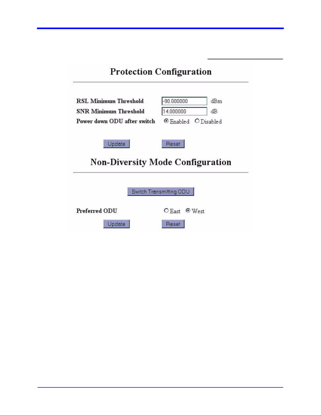
3-58
3.3.31 Protection Configuration
User Interface Manual
User Access Level: Level 3
Figure 3-39. Protection Configuration
3.3.31.1 Description
This screen enables the user to configure the following protection parameters
(see Figure 3-39).
1. Power down ODU after switch – Enable/Disable querying the faulted
ODU for its status.
2. Preferred ODU selection (only in protected 1+1 mode).
3.3.31.2 WEB Configuration
1. To change RSL Minimum Threshold and SNR Minimum Threshold values,
enter required value in the text box and click “update” button.
2. To Enable/Disable “Power down ODU after switch” parameter, select the
required radio button and press “Update” button.
MDS FIVE Series
05-4574A01, Rev. C
© Copyright 2006 Microwave Data Systems Inc. All Rights Reserved
Page 73

User Interface Manual
3. To select a Preferred ODU (only in protected 1+1 mode), click on the radio
button (East/West) and press the “update” button.
3.3.31.3 SNMP Configuration
1. Select a parameter from the MIB section
ccmSDIDULinkCfgRadioLinkProtection.
2. Use the SNMP GET command to set the value of the required parameter.
3. The SNMP agent will return the actual value upon successful set or get
operation. Upon failure, the SNMP agent will return an error if value is set
our of range, or the agent is not able to get or set the value or the user
does not have access rights to the selected parameter.
3.3.32 Link Configuration Wizard
3-59
User Access Level: Level 2
Figure 3-40. Link Configuration Wizard
3.3.32.1 Link Wizard Description
This screen enables the user to configure Framer and ODU related parameters.
The entire Framer and ODU configuration is divided across many pages, the first
of which is shown in Figure 3-40. The pages are:
1. ODU op-mode page – To select ODU operation mode.
2. IDU op-mode page – To select IDU operation mode.
3. ODU configuration page – To configure ODU type, polarization, alignment
mode and starting TX power.
4. ODU channel plan page – To select channel number for ODU.
5. Summary page – Displays all parameter values as selected by the user
from the proceeding pages. Upon pressing the “update” button, all Framer
and ODU parameters are updated.
© Copyright 2006 Microwave Data Systems Inc. All Rights Reserved
MDS FIVE Series
05-4574A01, Rev. C
Page 74

3-60
1. A single set of Framer and ODU parameters will be
displayed for the “standard” ODU operational mode.
Note
2. A single set of Framer parameters and two sets of ODU
parameters will be displayed for the “Protected” ODU opmode.
3.
Two sets of Framer and ODU parameters will be displayed,
if the ODU op-mode selected on the first page of the wizard
is “East-West”
3.3.32.2 WEB Configuration
1. Navigate to and click on the “Link configuration” link in the left panel.
2. Select ODU op-mode and click the “next” button.
3. Select IDU op-mode and click the “next” button. In the case of East-West
mode, two independent IDU op-modes can be selected.
4. Select ODU type, Polarization, and Alignment Mode. Enter Starting TX
Power and press the “next” button.
5. Select/Enter ODU Channel Number and press the “next” button.
6. All the above selected parameters are displayed in the summary page.
Verify all values and press the “update” button. To reconfigure, click the
“redo” button in summary page.
7. After pressing the “Update” button, a new page will display the status of
the link configuration.
User Interface Manual
.
MDS FIVE Series
05-4574A01, Rev. C
Warning
Note
Note
To configure the Framer and ODU related parameters, a standard
IO card and modem should be configured and present. Otherwise
an error message will be displayed.
In the Link Configuration Wizard, use only “back”/ “next” button
given in the web page to move to previous/next page. Do not
use the browser back button.
If the selected parameters on the current page are not supported
by the terminal, an error message will be displayed on the next
page. To correct the error, go back to the previous page and
select a different value for that parameter.
© Copyright 2006 Microwave Data Systems Inc. All Rights Reserved
Page 75

User Interface Manual
3.3.32.3 CLI Configuration
1. Navigate to IDU ConfigurationÆRadio LinkÆRadio WizardÆODU
opmode Screen
2. Select ODU op-mode using the Space Bar key and press the Enter key.
Then press the hotkey to switch to the Framer IDU operation mode
Selection Screen.
3. Select IDU op-mode using the Space Bar key and press the Enter key. In
the case of East-West mode, two independent IDU op-modes can be
selected.
4. Select the ODU type, Polarization and Alignment Mode using the Space
Bar key and press the Enter key. Enter the Starting TX Power. Then, press
the hotkey to switch to ODU East Channel Selection Screen
5. Select ODU East Channel Number using the Space Bar key and press the
Enter key. Then, press the hotkey to switch to the Reconfigure Framer
Screen
6. If the ODU Opmode is East-West, then the user can select the ODU West
channel number by switching to the ODU West Channel Selection Screen.
7. The selected parameters will be displayed in the summary page. Verify all
values. To update, press the hotkey for “Update IDU Config Params”. To
reconfigure, press the hotkey for “Radio Wizard – ODU opmode
Selection”.
3-61
To configure the Framer and ODU related parameters, a standard
IO card and modem should be configured and present. Otherwise
an error message will be displayed.
Warning
If the selected parameters in the current screen are not supported
by the system, an error message will be displayed on the next
Note
page. Go back to the previous screen by pressing the Esc key and
select a suitable value for that parameter
3.3.32.4 SNMP Configuration
1. Select a parameter from the MIB section ccmSDIDULinkCfgRadioLink
2. Use the SNMP GET command to get the value of the required parameter
3. Use the SNMP SET command to set the value of the required parameter
4. The SNMP agent will return the actual value upon successful set or get
operation. Upon failure, the SNMP agent will return an error if the value set
is out of range, or the agent is not able to get or set the value, or the user
does not have access rights to the selected parameter
.
© Copyright 2006 Microwave Data Systems Inc. All Rights Reserved
MDS FIVE Series
05-4574A01, Rev. C
Page 76

3-62
User Interface Manual
Wizard-style action in SNMP is achieved by setting a MIB object
“ccmSDIDULinkCfgMode”. If this MIB object is enabled then the entire Link
configuration will be updated into the temporary wizard section. After the full
configuration, the “ccmSDIDURadioLinkReconfigure” MIB object needs to be set
to reflect the changes made.
A detailed procedure for link configuration through SNMP is listed below
1. SET the ODU Opmode by setting the “ccmSDIDULinkCfgODUOpMode”
MIB object.
2. GET the IDU opmode list by reading the MIB
“ccmSDIDULinkUtilIDUEastOpmodeList”. “List” will give the list of possible
op modes. Select a number corresponding to the required opmode.
3. SET IDU op-mode by setting the number selected above in to MIB object
“ccmSDIDULinkEastOpModeIndex”
4. GET the “ccmSDIDULinkUtilEastODUChList” MIB variables value
5. SET the channel number gotten above in to the
“ccmSDIDURadioEastODUCfgChFreq”.
6. Update the configurations done so far using
“ccmSDIDURadioLinkReconfigure”
7. The selected configuration row index can be viewed by reading the MIB
“ccmSDIDULinkUtilEastChRowIndex”
3.3.33 ODU Power
3.3.33.1 Description
The screen shown in Figure 3-41 enables the user to configure the ODU power.
The following parameters are displayed
User Access Level: Level 2
Figure 3-41. ODU Power
MDS FIVE Series
05-4574A01, Rev. C
© Copyright 2006 Microwave Data Systems Inc. All Rights Reserved
Page 77

User Interface Manual
1. Start Tx Power - To change the starting Tx power of ODU.
2. Current Tx Power – To display the current Tx power.
3.3.33.2 WEB Configuration
1. Select the required Start Tx Power by pressing the UP or DOWN arrows
and click the “update” button.
3.3.34 ODU Channel wizard
3-63
User Access Level: Level 2
Figure 3-42. ODU Channel
3.3.34.1 ODU Wizard Description
This screen enables the user to configure ODU related parameters. The ODU
configuration is divided into many pages, the first of which is shown in Figure 3-
42. The pages are:
1. ODU Configuration page – To configure ODU type and polarization.
2. ODU Channel Selection page – To select the channel number and
alignment mode.
A single set of ODU parameters will be displayed for the
“standard” ODU op-mode.
Note
Two sets of ODU parameters will be displayed for the
“Protected” and “East-West” ODU op-modes.
© Copyright 2006 Microwave Data Systems Inc. All Rights Reserved
MDS FIVE Series
05-4574A01, Rev. C
Page 78

3-64
3.3.34.2 WEB Configuration
1. Navigate to and click on the “ODU configuration” link in the left panel.
2. Select the ODU type, polarization and alignment mode. Then click the
“next” button.
3. Select the ODU channel number/alignment mode and press the “next”/
“update” button.
To configure ODU related parameters, a modem should be
configured and present. Otherwise an error message will be
displayed.
Warning
In the Link Configuration Wizard, use only “back”/ “next” button
given in the web page to move to previous/next page. Do not
Note
use the browser back button.
User Interface Manual
If the selected parameters on the current page are not supported
by the terminal, an error message will be displayed on the next
Note
page. To correct the error, go back to the previous page and
select a different value for that parameter.
3.3.34.3 CLI Configuration
1. Navigate to IDU ConfigurationÆRadio LinkÆIDU ODU
ConfigurationÆODU Configuration.
2. Select the ODU type and polarization using the Space Bar key and press
the Enter key. Enter the starting TX power and press the hotkey to switch
to the ODU Channel selection screen.
3. Select the ODU channel number and press the hotkey for “update.”
To configure ODU related parameters, a modem should be
configured and present. Otherwise an error message will be
Warning
displayed.
MDS FIVE Series
05-4574A01, Rev. C
© Copyright 2006 Microwave Data Systems Inc. All Rights Reserved
Page 79

User Interface Manual
If the selected parameters in the current screen are not supported
by the system, an error message will be displayed on the next
Note
page. Go back to the previous screen by pressing the Esc key and
select a suitable value for that parameter
3.3.34.4 SNMP Configuration
1. Select a parameter from the MIB section
ccmSDIDULinkCfgRadioLinkEastODUCfg
2. Use the SNMP GET command to get the value of the required parameter
3. Use the SNMP SET command to set the value of the required parameter
4. The SNMP agent will return the actual value upon successful set or get
operation. Upon failure, the SNMP agent will return an error if the value set
is out of range, or the agent is not able to get or set the value, or the user
does not have access rights to the selected parameter.
Details of the ODU configuration are given below
3-65
.
1. GET the “ccmSDIDULinkUtilODUTypeCapability”,
2. Select ODU type gotten above into MIB variables
“ccmSDIDURadioEastODUCfgType
3. GET the “ccmSDIDULinkUtilEastODUChList” MIB variables value
4. SET the channel frequency gotten above into the
“ccmSDIDURadioEastODUCfgChFreq”.
5. update the ODU configuration by setting the MIB
“ccmSDIDURadioEastODUCfgChFreqReconfigure”.
© Copyright 2006 Microwave Data Systems Inc. All Rights Reserved
MDS FIVE Series
05-4574A01, Rev. C
Page 80

3-66
3.3.35 ODU Configuration
User Interface Manual
User Access Level: Level 3
Figure 3-43. ODU Configuration
3.3.35.1 Description
This screen enables the user to configure the ODU and is shown in Figure 3-43.
The spiral search function is not generally used for operation links. The function is
included to allow for carrier searches when oscillators are far off in frequency or
for testing ODU performance.
3.3.35.2 WEB Configuration
1. Click on the radio button to select the ODU (East/West).
2. Press the Disable, Enable, Mute, or Unmute button.
3. In the case of Protected mode, the mute and unmute options will not be
available.
4. Click on the radio button to Enable or Disable Spiral Search. For general
operation, this option should be disabled.
5. The Spiral Search Window value can be entered in the text box and it
should be within the range specified.
6. Press the Update button to update the Spiral Search Values.
MDS FIVE Series
05-4574A01, Rev. C
© Copyright 2006 Microwave Data Systems Inc. All Rights Reserved
Page 81

User Interface Manual
7. Press the Reset button to reset the Spiral Search Values.
3.3.35.3 SNMP Configuration
1. Use an SNMP Set on the OID ccmSDIDURadioWestODUStateConfig or
ccmSDIDURadioEastODUStateConfig to disable (1) or enable (2) the
ODU.
2. Use an SNMP Set on the OID ccmSDIDURadioWestODUMuteConfig or
ccmSDIDURadioEastODUStateConfig to unmute (1) or mute (2) the ODU.
3. Use an SNMP Set on the OID ccmSDIDULinkUtilODUSpiralSearch to
disable (1) or enable (2) the spiral search.
4. Use an SNMP Set on the OID ccmSDIDULinkUtilSpiralSearchWindow to
enter in the search window value. This OID will take an integer input that
represents the search window value in kHz.
3-67
© Copyright 2006 Microwave Data Systems Inc. All Rights Reserved
MDS FIVE Series
05-4574A01, Rev. C
Page 82

3-68
3.3.36 Alarm Threshold
User Interface Manual
User Access Level: Level 2
Figure 3-44. Alarm Configuration
3.3.36.1 Description
This screen enables the user to configure the following alarm threshold
parameters (see Figure 3-44).
1. RSL alarm threshold – Threshold value for RSL alarm in ‘dBm’ units.
2. Signal/Noise threshold - Threshold value for Signal/Noise alarm in ‘dB’
units.
3. External alarm signal level – Active Low or High.
3.3.36.2 WEB Configuration
1. Navigate to Analysis and click on the “Alarm” link in the left panel.
MDS FIVE Series
05-4574A01, Rev. C
© Copyright 2006 Microwave Data Systems Inc. All Rights Reserved
Page 83

User Interface Manual
2. Now click on the “Threshold” link.
3. The alarm threshold parameters will be displayed with current/present
values.
4. Change the required parameters and click the “Update” button.
5. The page will be refreshed and displayed with updated values.
6. If parameters are not updated with entered values, the value entered may
be invalid for that parameter.
7. Based on the “External Alarm signal level” radio button selection, the
External alarm input jumper positions will be displayed.
3.3.36.3 SNMP Configuration
1. Select a parameter from the MIB section
ccmSDIDUAnalysisAlarmThreshold
2. Use the SNMP GET command to get the value of the required parameter
3. Use the SNMP SET command to set the value of the required parameter
4. The SNMP agent will return the actual value upon successful set or get
operation. Upon failure, the SNMP agent will return an error if the value set
is out of range, or the agent is not able to get or set the value, or the user
does not have access rights to the selected parameter
3-69
© Copyright 2006 Microwave Data Systems Inc. All Rights Reserved
MDS FIVE Series
05-4574A01, Rev. C
Page 84

3-70
3.3.37 Alarm Configuration
User Interface Manual
User Access Level: Level 2
3.3.37.1 Description
This screen enables the user to configure the following attributes of the terminal
alarms (see Figure 3-45).
1. Description – Description of the alarm.
2. Mask – masking a particular alarm. If checked , that particular alarm
will be ignored.
3. E-mail – If checked , upon occurrence of this alarm the configured
users are notified by E-mail. To configure e-mail parameters, see the email configuration section (Section 3.3.6)
4. Severity – Type of the alarm (Critical, Major and Info).
5. AL1 – AL4 – Maps alarm output to one of the four external alarm outputs.
For a full list of alarms, see Section 6.3.
MDS FIVE Series
05-4574A01, Rev. C
Figure 3-45. Alarm Configuration
© Copyright 2006 Microwave Data Systems Inc. All Rights Reserved
Page 85

User Interface Manual
3.3.37.2 WEB Configuration
1. Navigate to Analysis and click on the “alarm” link in the left panel.
2. Now click on the “Discrete” link.
3. All alarm attributes will be displayed with current/present values.
4. Change the required parameters and click the “Update” button.
5. The page will be refreshed and displayed with current/present values.
6. All the checkboxes for E-mail notification may be selected by pressing the
button “Check All Mails”.
7. All the checkboxes for E-mail notification may be deselected by pressing
the button “Clear All Mails”.
8. All the checkboxes for masking the alarms may be selected by pressing
the button “Check All Masks”.
9. All the masks may be deselected by pressing the button “Clear All Masks”.
10. If an alarm is active (set), the description of that alarm will be red in color.
3.3.37.3 SNMP Configuration
3-71
1. Select a parameter from the MIB section ccmSDIDUAnalysisAlarm, under
ccmSDIDUAnalysis group
2. Use the SNMP GET command to get the value of the required parameter
3. Use the SNMP SET command to set the value of the required parameter
4. The SNMP agent will return the actual value upon successful set or get
operation. Upon failure, the SNMP agent will return an error if the value set
is out of range, or the agent is not able to get or set the value, or the user
does not have access rights to the selected parameter
Use MIB objects ccmSDIDUAlarmMask and ccmSDIDUAlarmEmailMask for
accessing alarm and E-mail masks respectively. Alarm masks will be in the
following format
1=U:2=U:1=U:3=U:4=U:5=U:6=U:7=U:8=U:9=U:10=U:11=U:
use “M” to mask the alarm and “U” to unmask the alarm.
© Copyright 2006 Microwave Data Systems Inc. All Rights Reserved
MDS FIVE Series
05-4574A01, Rev. C
Page 86

3-72
3.3.38 Alarm History
User Interface Manual
User Access Level: Level 2
3.3.38.1 Description
This screen lists alarms that have occurred and their description, status, and time
(see Figure 3-46). A maximum of 300 alarms can be displayed. If the alarm history
exceeds 300 alarms, the oldest alarms will be removed/overwritten. The following
items are displayed on this page:
1. Description – Description (name) of the alarm.
2. Status – Status of alarm (set/reset).
3. Time - The time at which the particular alarm set/reset.
4. Clear History – The button used to clear the Alarm History records.
The current alarm state can be obtained from the SNMP manager by reading an
MIB object ccmSDIDUAlarmStatus from the ccmSDIDUAnalysis section. Status
will be returned as string, for example
1=I:2=I:3=I:4=I:5=A:6=I:7=I:8=I:9=I:10=I:11=I:
where “I” indicates that the alarm is inactive and “A” indicates the alarmed state.
Figure 3-46. Alarm History
MDS FIVE Series
05-4574A01, Rev. C
© Copyright 2006 Microwave Data Systems Inc. All Rights Reserved
Page 87

User Interface Manual
3.3.39 Active Alarms
3-73
User Access Level: Level 2
Figure 3-47. Active Alarms
3.3.39.1 Description
This screen shown in Figure 3-47 displays active alarm information including:
1. Description – Description (name) of the alarm.
2. Time - The time at which this particular alarm set
The last 100 alarms are stored in non-volitile memory and will be
available after a power cycle.
Note
© Copyright 2006 Microwave Data Systems Inc. All Rights Reserved
MDS FIVE Series
05-4574A01, Rev. C
Page 88

3-74
3.3.40 Graphs
User Interface Manual
User Access Level: Level 1
Figure 3-48. SNR Plot
MDS FIVE Series
05-4574A01, Rev. C
Figure 3-49. Equalizer Taps
© Copyright 2006 Microwave Data Systems Inc. All Rights Reserved
Page 89

User Interface Manual
3-75
Figure 3-50. Constellation Display (64 QAM)
3.3.40.1 Description
This screen presents the following parameters graphically:
1. East RSL
2. West RSL
3. East Signal/Noise
4. West Signal/Noise
5. East TX power
6. West TX power
7. East Error second count
8. West Error second count.
9. East Equalizer Taps
10. West Equalizer Taps
11. East Constellation
12. West Constellation
13. Mux/Demux
14. Temperature
For parameters 1-8, the last 24 hours of data will be plotted with the parameter
along the Y-axis (vertical) and time along the X-axis (horizontal) as in Figure 3-48.
© Copyright 2006 Microwave Data Systems Inc. All Rights Reserved
MDS FIVE Series
05-4574A01, Rev. C
Page 90

3-76
Equalizer Taps and Constellations are plotted as shown in Figure 3-49 and Figure
3-50.
3.3.40.2 WEB Configuration
1. Navigate to Analysis and click on the “Graphs” link in the left panel.
2. Based on the ODU operation mode configuration, the number of graphs
displayed will differ. For example, if the ODU operation is East-West, all 8
parameters’ graphs will be accessible. If the ODU operation mode is not
East-West, only 4 (either East or West) graphs will be accessible.
3. Select any one link to view the graph of that parameter.
4. The X-axis time range can be selected. (From 1,2,4,12 or 24). If 1 hour is
selected, it will plot the graph using last hour of data.
5. When the mouse is moved over the graph area, the corresponding value
at the mouse point will be displayed under the graph area. This enables
the user to easily read X and Y values.
3.3.40.3 SNMP Configuration
User Interface Manual
From SNMP manager graph data can be obtained by reading a MIB object
ccmSDIDUAnalysisPerfData from the ccmSDIDUAnalysis section.
MDS FIVE Series
05-4574A01, Rev. C
© Copyright 2006 Microwave Data Systems Inc. All Rights Reserved
Page 91

User Interface Manual
3.3.41 Statistics – Data Switch
3-77
User Access Level: Level 1
Figure 3-51. Data Switch Statistics
3.3.41.1 Description
This screen provides:
1. Rx Bytes
2. Rx Bytes/sec
3. TX Bytes
4. TX Bytes/sec
5. Rx Frames
6. Rx Frames/sec
7. TX Frames
8. TX Frames/sec
9. Errors
10. Errors/sec
© Copyright 2006 Microwave Data Systems Inc. All Rights Reserved
MDS FIVE Series
05-4574A01, Rev. C
Page 92

3-78
11. Collisions
12. Collisions/sec
for Port 1, Port 2, CPU, Radio Link (East) and Radio Link (West) of the Data
Switch, as shown in Figure 3-51.
3.3.41.2 WEB Configuration
1. Navigate to Analysis -> Statistics and click on the “Data Switch” link in the
left panel.
2. Press the “Clear” button to clear the data and start accumulating again.
3.3.41.3 CLI Configuration
Navigate to Analysis -> Data Switch Statistics
3.3.41.4 SNMP Configuration
User Interface Manual
1. Select a parameter from the MIB section ccmSDIDUAnalysisUPLSwitch
2. Use the SNMP GET command to get the value of the required parameter
3. The SNMP agent will return the actual value on successful get operation.
Upon failure, the SNMP agent will return an error if agent is not able to get
the value or the user does not have access rights to the selected
parameter.
MDS FIVE Series
05-4574A01, Rev. C
© Copyright 2006 Microwave Data Systems Inc. All Rights Reserved
Page 93
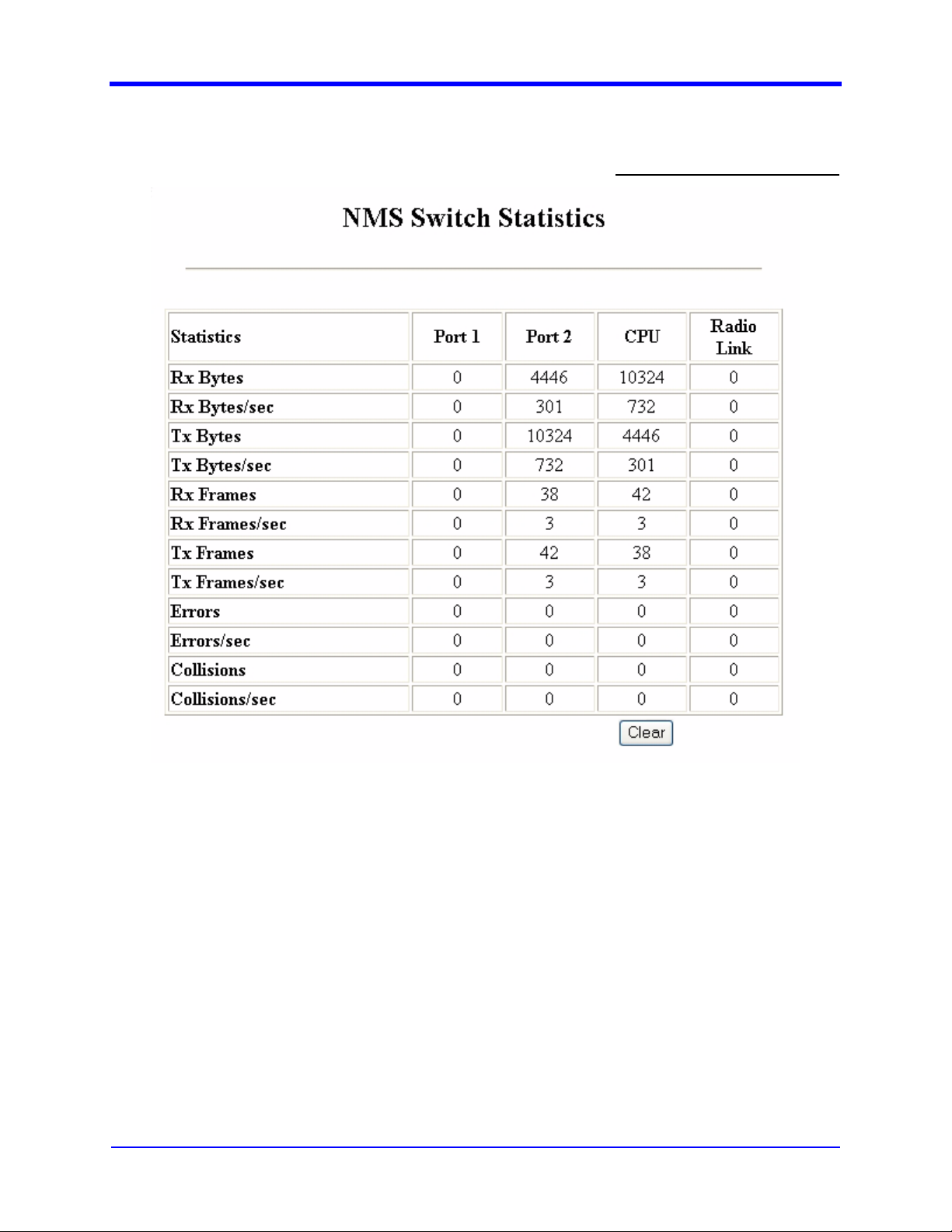
User Interface Manual
3.3.42 Statistics – NMS Switch
3-79
User Access Level: Level 1
Figure 3-52. NMS Switch Statistics
3.3.42.1 Description
This screen provides:
1. Rx Bytes
2. Rx Bytes/sec
3. TX Bytes
4. TX Bytes/sec
5. Rx Frames
6. Rx Frames/sec
7. TX Frames
8. TX Frames/sec
© Copyright 2006 Microwave Data Systems Inc. All Rights Reserved
MDS FIVE Series
05-4574A01, Rev. C
Page 94

3-80
9. Errors
10. Errors/sec
11. Collisions
12. Collisions/sec
for Port 1, Port 2, CPU, Radio Link (East) and Radio Link (West) of the NMS
Switch, as shown in Figure 3-52.
3.3.43 WEB Configuration
1. Navigate to Analysis -> Statistics and click on the “NMS Switch” link in the
left panel.
2. Press the “Clear” button to clear the data and start accumulating again.
3.3.44 CLI Configuration
Navigate to Analysis -> SNMP Switch Statistics.
User Interface Manual
3.3.45 SNMP Configuration
1. Select a parameter from the MIB section ccmSDIDUAnalysisNMSSwitch
2. Use the SNMP GET command to get the value of the required parameter
3. The SNMP agent will return the actual value on successful get operation.
Upon failure, the SNMP agent will return an error if agent is not able to get
the value or the user does not have access rights to the selected
parameter.
MDS FIVE Series
05-4574A01, Rev. C
© Copyright 2006 Microwave Data Systems Inc. All Rights Reserved
Page 95

User Interface Manual
3.3.46 BERT Mode
3-81
User Access Level: Level 2
3.3.46.1 Description
This screen is used to communicate with the MODEM directly by sending a
command and receiving the response (see Figure 3-53). The following items are
displayed
1. East/West Enable/Disable– For selecting East/West and Enable/Disable.
2. “Clear” button – send the “clear” command to the MODEM.
3. Insert Bit Error - Insert a bit error
4. Text Area – To display the response messages from MODEM.
5. Cumulative Bits - Total number of bits
6. Cumulative Bit Error - Total number of error bits
7. Bit Error Rate - Percentage of error bits
To use the SDIDU™’s BERT capabilities, the BERT mode has to be enabled
independently at both ends of the link because there is no separate NMS stream
when operating in BERT mode. This will require the use of two PCs, one
connected directly to the NMS port of each SDIDU™.
Figure 3-53. BERT Mode
© Copyright 2006 Microwave Data Systems Inc. All Rights Reserved
MDS FIVE Series
05-4574A01, Rev. C
Page 96

3-82
3.3.47 WEB Configuration
To begin testing:
1. Navigate to Analysis and click on the “BERT mode” in the left panel.
2. Enable one of the SDIDU™'s BERT mode.
a. Click on one command. (East Enable or West Enable).
b. After few seconds (depending on your network speed) the response
from MODEM for the given command will be displayed in the text area.
c. Enabling this mode will generate random data over the link causing the
other SDIDU to trigger the buzzer, generating noise.
3. Enable the other SDIDU™'s BERT mode. This should silence the buzzer
noise.
4. Send the “Clear” command to both SDIDUs™ to reset the cumulative bits,
cumulative bit errors, and bit error rate counters.
a. Click on the “Clear” button.
b. After few seconds (depending on your network speed) the response
from MODEM for the given command will be displayed in the text area.
5. Every time the response message will be appended at the end, so using
the scroll bar you can see all messages.
6. To insert an error and see whether the modem catches it, click on the
“Insert Bit Error” button.
User Interface Manual
To stop testing:
1. Disable one of the SDIDU's BERT mode.
a. Click on one command. (East Disable or West Disable),
b. This will cause this SDIDU to generate buzzer noise.
2. Disable the other SDIDU's BERT mode, this should silence the buzzer
noise.
Number of Bits, Bit Errors, and BER will be accumulated until the BERTs are
disabled, or the SDIDUs are power cycled, which will clear the BERT mode.
The MODEM may generate unsolicited messages without any
command being sent from this screen. These messages are
Note
also appended in the text area.
MDS FIVE Series
05-4574A01, Rev. C
© Copyright 2006 Microwave Data Systems Inc. All Rights Reserved
Page 97

User Interface Manual
3-83
To copy & save the response messages
Note
3.3.48 CW Mode
3.3.48.1 Description
1. Click inside the text area.
2. Press Ctrl+A and Ctrl+C.
3. Open notepad (or any text editor) and press Ctrl+V.
4. Save the file.
User Access Level: Level 2
Figure 3-54. CW Mode
This screen allows the user to enable or disable CW mode (see Figure 3-54).
When set to CW mode, the modem generates a tone rather than a modulated
signal. This mode is used for non-operational purposes, such as calibration and
pointing.
3.3.48.2 WEB Configuration
Select required mode (East/West) and press the “Enable” or “Disable” button. A
status message will be displayed to indicate success/failure. When CW mode is
enabled, the transmitter status in the “status panel” (Right side panel) will display
“CW Mode”.
3.3.48.3 SNMP Configuration
1. Select a parameter from the MIB section
ccmSDIDUAnalysisModemConfig.
2. Use the SNMP GET command to get the value of the required parameter.
3. Use the SNMP SET command to set the value of the required parameter.
© Copyright 2006 Microwave Data Systems Inc. All Rights Reserved
MDS FIVE Series
05-4574A01, Rev. C
Page 98
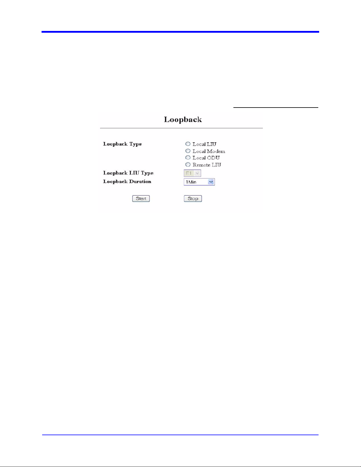
3-84
4. The SNMP agent will return the actual value upon successful set or get
operation. Upon failure, the SNMP agent will return an error if the value set
is out of range, or the agent is not able to get or set the value, or the user
does not have access rights to the selected parameter.
3.3.49 Loopback
User Interface Manual
User Access Level: Level 2
Figure 3-55. Loopback
3.3.49.1 Description
This screen enables the user to start or stop Loop Back (see Figure 3-55). Not all
ODUs support ODU loopback.
3.3.49.2 WEB Configuration
1. Navigate to AnalysisÆLoopback.
2. Select the type of loopback (Local LIU, Local Modem, Local ODU or
Remote LIU).
3. If Local or Remote LIU is selected then select the LIU type from the drop
down option.
4. Select the duration of the loopback.
5. Press the start Button to start loopback.
6. If loopback is running, press the stop button to stop it.
3.3.49.3 CLI Configuration
MDS FIVE Series
05-4574A01, Rev. C
1. Navigate to AnalysisÆ LoopBack.
© Copyright 2006 Microwave Data Systems Inc. All Rights Reserved
Page 99

User Interface Manual
2. Select the type of loopback (Local LIU, Local Modem, Local ODU or
Remote LIU) by pressing appropriate hotkey and the space bar.
3. If Local or Remote LIU is selected then select the LIU type.
4. Select the duration of the loopback by pressing appropriate hotkey and the
space bar.
5. To start loopback, press the hotkey for Start.
6. To revert to the previous value, press the “Esc” key while editing the value
7. If loopback is running, press the hotkey for stop to stop it.
3.3.49.4 SNMP Configuration
1. Select a parameter from the MIB section c ccmSDIDUAnalysisLoopback
2. Use the SNMP GET command to get the value of the required parameter
3. Use the SNMP SET command to set the value of the required parameter
4. The SNMP agent will return the actual value upon successful set or get
operation. Upon failure, the SNMP agent will return an error if the value set
is out of range, or the agent is not able to get or set the value, or the user
does not have access rights to the selected parameter.
3-85
3.3.50 Modem Temperature
3.3.50.1 SNMP Configuration
1. Select a parameter (ccmSDIDUModemEastTemperature or
ccmSDIDUModem West Temperature) from the MIB section
ccmSDIDUAnalysisModemConfig
2. Use the SNMP GET command to get the value of the required parameter
3. The SNMP agent will return the actual value upon successful set or get
operation. Upon failure, the SNMP agent will return an error the agent is
not able to get or set the value, or the user does not have access rights to
the selected parameter.
© Copyright 2006 Microwave Data Systems Inc. All Rights Reserved
MDS FIVE Series
05-4574A01, Rev. C
Page 100

3-86
3.3.51 Logout
3.3.51.1 Description
User Interface Manual
User Access Level: Level 1
Figure 3-56. Logout
The page shown in Figure 3-56 enables the user to logout from the Web Interface.
In the case of Internet Explorer, the logout link will close the browser. For other
browsers, the user may have to close and reopen the browser.
MDS FIVE Series
05-4574A01, Rev. C
© Copyright 2006 Microwave Data Systems Inc. All Rights Reserved
 Loading...