

Microwave Data Systems MDS 1710 A, MDS 2710A, MDS 2710D, MDS 2710C, MDS 1710 C Operation Manual
Microwave Data Systems Inc.
Rochester, NY 14620
General Business: +1 585 242-9600
FAX: +1 585 242-9620
Web: www.microwavedata.com
175 Science Parkway
A product of Microwave Data Systems Inc.
Installation & Operation Guide
MDS 05-3447A01, REV. F
SEPTEMBER 2004
Data Transceiver
Microwave Data Systems Inc.
MDS 1710 A/C
MDS 2710A/C/D
QUICK START GUIDE
Below are the basic steps for installing the transceiver. Detailed instructions are provided in “Installation
Steps” on Page 9 of this manual.
1. Install and connect the antenna system to the radio
• Use good quality, low loss coaxial cable. Keep the feedline as short as possible.
• Preset directional antennas in the direction of desired transmission/reception.
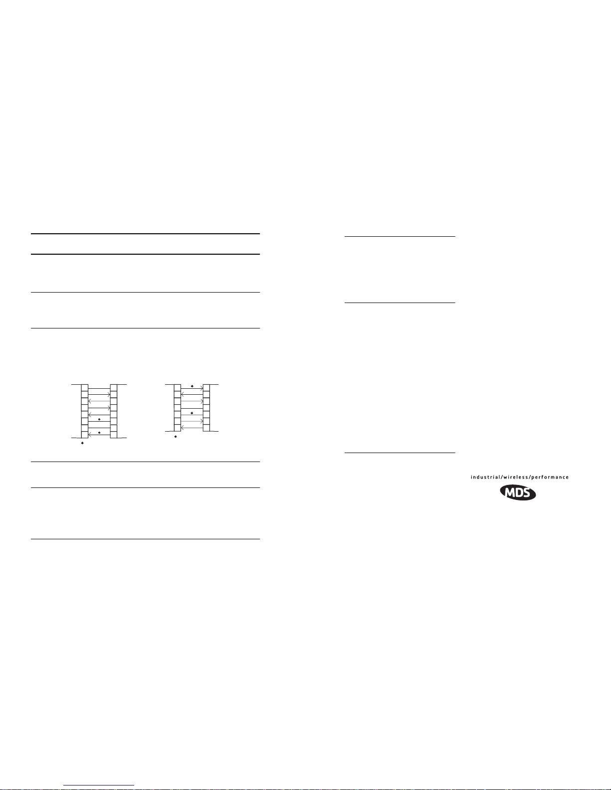
2. Connect the data equipment to the radio’s INTERFACE connector
• Connection to the radio must be made with a DB-25 Male connector. Connections for typical systems are shown below.
• Connect only the required pins. Do not use a straight-through RS-232 cable with all pins wired.
•Verify the data equipment is configured as DTE. (By default, the radio is configured as DCE.)
3. Apply DC power to the radio (10.5–16 Vdc @ 2.5 A minimum)
• Observe proper polarity. The red wire is the positive lead; the black is negative.
4. Set the radio’s basic configuration with a Hand-Held Terminal (HHT)
• Set the transmit frequency (
TX xxx.xxxxx
).
• Set the receive frequency (
RX xxx.xxxxx
).
• Set/verify the data rate using the
BAUD
command. The default setting is
BAUD 4800 8N1
. (Refer to
“TRANSCEIVER PROGRAMMING” on Page 17 for command details.)
5. Verify proper operation by observing the LED display
• Refer to Tab le 5 on Page 16 for a description of the status LEDs.
•Refine directional antenna headings for maximum receive signal strength using the
RSSI
com-
mand.
DB-25 DB-25
2
3
2
3
4
5
20
6DSR
DSR
6
TXD
RXD
GND
RTS
CTS
TXD
RXD
GND
4
CTS
5
RTS
DB-9 DB-25
DB-9 to DB-25 ExampleDB-25 to DB-25 Example
11
4
5
2
3
3
2
5
20
7
RXD
TXD
DCD
GND
DSR
RTS
RXD
TXD
DCD
GND
As required for application
5
18
7
6
CTS
DSR
RTS
CTS8
6
4
5
77
GND
GND
8 8
DCD
DCD
As required for application
RTU
(DTE)
TRANSCEIVER
(DCE)
RTU
(DTE)
TRANSCEIVER
(DCE)
IN CASE OF DIFFICULTY...
MDS products are designed for long life and
trouble-free operation. However, this equipment, as with all electronic equipment may
have an occasional component failure. The
following information will assist you in the
event that servicing becomes necessary.
FACTORY TECHNICAL
ASSISTANCE
Technical assistance for MDS products is
available from our Customer Support Team
during business hours (8:00 A.M.–5:30 P.M.
Eastern Time). When calling, please give the
complete model number of the radio, along
with a description of the trouble symptom(s)
that you are experiencing. In many cases, problems can be resolved over the telephone,
without the need for returning the unit to the
factory.
Please use one of the following means for
product assistance:
Phone: 585-241-5510
E-mail: techsupport@microwavedata.com
Web: www.microwavedata.com
FAX: 585-242-8369
FACTORY REPAIRS
Component-level repair of radio equipment is
not recommended in the field. Many compo-
nents are installed using surface mount technology, which requires specialized training
and equipment for proper servicing. For this
reason, the equipment should be returned to
the factory for any PC board repairs. The
factory is best equipped to diagnose, repair and
align your radio to its proper operating specifications.
If return of the equipment is necessary, you
will be issued a Service Return Order (SRO)
number. The SRO number will help expedite
the repair so that the equipment can be repaired
and returned to you as quickly as possible.
Please be sure to include the SRO number on
the outside of the shipping box, and on any
correspondence relating to the repair. No
equipment will be accepted for repair without
an SRO number.
A statement should accompany the radio
describing, in detail, the trouble symptom(s),
and a description of any associated equipment
normally connected to the radio. It is also
important to include the name and telephone
number of a person in your organization who
can be contacted if additional information is
required.
The radio must be properly packed for return
to the factory. The original shipping container
and packaging materials should be used whenever possible. All factory returns should be
addressed to:
When repairs have been completed, the equipment will be returned to you by the same shipping method used to send it to the factory.
Please specify if you wish to make different
shipping arrangements. To inquire about an inprocess repair, you may contact our Product
Services Group at: 585-241-5540 (FAX: 585242-8400) or vie e-mail at:
ProductServices@microwavedata.com.
Microwave Data Systems Inc.
Product Service Department
(SRO No. XXXX)
175 Science Parkway
Rochester, NY 14620 USA

I-6 MDS 1710A/C and MDS2710A/C/D MDS 05-3447A01, Rev. F
NOTES
MDS 05-3447A01, Rev. F MDS 1710A/C and MDS 2710A/C/D i
TABLE OF CONTENTS
1.0 GENERAL.................................................................................... 1
1.1 Introduction ......................................................................................1
1.2 Differences Between Models ...........................................................2
1.3 Applications ...................................................................................... 2
Point-to-Multipoint, Multiple Address Systems (MAS) ....................2
Point-to-Point System..................................................................... 3
Continuously Keyed versus Switched Carrier Operation................ 4
Single Frequency (Simplex) Operation........................................... 4
1.4 Product Configurator Codes .............................................................4
1.5 Accessories ...................................................................................... 5
2.0 GLOSSARY OF TERMS.............................................................. 5
3.0 INSTALLATION ............................................................................ 8
3.1 Installation Steps .............................................................................. 9
3.2 Transceiver Mounting .....................................................................11
3.3 Antennas and Feedlines ................................................................11
Feedlines ......................................................................................12
3.4 Power Connection .......................................................................... 12
3.5 Data Interface Connections ............................................................13
3.6 Using the Radio’s Sleep Mode ....................................................... 13
Sleep Mode Example ...................................................................13
4.0 OPERATION.............................................................................. 15
4.1 LED Indicators ................................................................................16
4.2 RSSI Measurement ........................................................................ 16
5.0 TRANSCEIVER PROGRAMMING ............................................17
5.1 Hand-Held Terminal Connection & Startup ....................................17
5.2 Hand-Held Terminal Setup .............................................................18
5.3 Keyboard Commands .....................................................................19
Entering Commands..................................................................... 19
Error Messages ............................................................................19
5.4 Detailed Command Descriptions ...................................................22
AMASK [0000 0000–FFFF FFFF] ................................................22
ASENSE [HI/LO]........................................................................... 23
BAUD [xxxxx abc]......................................................................... 23
BUFF [ON, OFF]........................................................................... 23
CKEY [ON–OFF] ..........................................................................24
CTS [0–255] .................................................................................24
DATAKEY [ON, OFF] ....................................................................24
DEVICE [DCE, CTS KEY] ............................................................24
DKEY............................................................................................ 25

ii MDS 1710A/C and MDS 2710A/C/D MDS 05-3447A01, Rev. F
DLINK [ON/OFF/xxxx] ..................................................................25
DMGAP [xx].................................................................................. 25
DTYPE [NODE/ROOT]................................................................. 25
DUMP ...........................................................................................26
HREV............................................................................................ 26
INIT............................................................................................... 26
INIT [2710].................................................................................... 26
INIT [2720].................................................................................... 26
KEY ..............................................................................................27
MODEL......................................................................................... 27
MODEM [xxxx, NONE] .................................................................27
OWM [XXX...] ...............................................................................27
OWN [XXX...]................................................................................ 27
PTT [0–255].................................................................................. 27
PWR [20–37] ................................................................................27
RSSI .............................................................................................28
RTU [ON/OFF/0-80]......................................................................28
RX [xxx.xxxxx] ..............................................................................28
RXTOT [NONE, 1-255]................................................................. 28
SCD [0-255].................................................................................. 28
SER ..............................................................................................28
SHOW [DC, PORT, PWR].............................................................29
SNR ..............................................................................................29
SREV............................................................................................ 29
STAT ............................................................................................. 29
TEMP............................................................................................ 29
TOT [1-255, ON, OFF] ..................................................................30
TX [xxx.xxxxx]............................................................................... 30
UNIT [10000...65000] ...................................................................30
6.0 TROUBLESHOOTING............................................................... 30
6.1 LED Indicators ................................................................................31
6.2 Event Codes ...................................................................................31
Checking for Alarms—STAT command.........................................31
Major Alarms vs. Minor Alarms..................................................... 31
Event Code Definitions .................................................................32
7.0 TECHNICAL REFERENCE .......................................................33
7.1 Transceiver Specifications ..............................................................33
7.2 Performing Network-Wide Remote Diagnostics ............................. 34
7.3 Bench Testing Setup ......................................................................36
7.4 Helical Filter Adjustment ................................................................37
7.5 Upgrading the Radio’s Software .....................................................38
Using Radio Software Upgrade Diskette ......................................38
Using Radio Configuration Software.............................................39
7.6 dBm-Watts-Volts Conversion Chart ................................................ 40
I-5 MDS 1710A/C and MDS2710A/C/D MDS 05-3447A01, Rev. F
length vs. loss in coaxial cables 12
Technical reference 33–40
Technical reference,
bench test setup,
36–37
TEMP command 29
Temperature, displaying internal (TEMP command) 29
Testing. See bench testing
TEXT TOO LONG error message
20
Timer, set/display time-out value and status (TOT command) 30
TOT command 30
Transceiver
applications
2
configuring for operation 10
connectors and indicators, illustrated 1
diagnostics using PC software 38
dimensions, mounting 11
mounting 9, 11
programming 17–20
specifications 33–34
upgrading software 38
Transmit Audio Input pinout (Pin 9) 14
Transmitter
specifications
33
system specifications 33
Troubleshooting 30–32
connecting Hand-Held Terminal (HHT) for displaying alarm
codes
17
performing network-wide diagnostics 34
STAT command (Status) 31
using PC software for 38
TX command 30
TXD LED
description
16
Pin 2 14
U
UNKNOWN COMMAND error message 19

I-4 MDS 1710A/C and MDS2710A/C/D MDS 05-3447A01, Rev. F
entering commands using the Hand-Held Terminal (HHT) 19
helical filter adjustment 37
installation 9
measuring RSSI with DC voltmeter 16
network-wide diagnostics 34
operation 15, 16
performance optimization 15
reading LED status indicators 16
resetting Hand-Held Terminal (HHT) 18
troubleshooting 30–32
Product
accessories 5
description 1
display model number code (MODEL command) 27
display radio serial number (SER command) 28
Programming radio as root or node 35
Programming, transceiver 17–20
PTT
command 27
pinout (Pins 14, 16) 14
PWR
command 27
LED 16
R
Radio
Configuration Software 5, 38
Inhibit pinout (Pin 12) 14
serial number, displaying (SER command) 28
Receive Audio Output pinout (Pin 11) 14
Receiver
specifications
34
system specifications 33
unsquelched signal (Pin 10) 14
Redundant operation, defined 8
Remote
RTU reset (Pin 15) 14
Station, defined 8
Station, illustrated 9
Resetting
Hand-Held Terminal (HHT) (SHIFT,CTRL,SPACE keys)
18
remote RTU reset (Pin 15) 14
transceiver (INIT command) 26
Revision level
display hardware (HREV command) 26
display software (SREV command) 29
RSSI
adjusting helical filter for increased signal strength
37
command 28
command, used to refine antenna heading 15
measuring 16
pinout (Pin 21) 15
vs. Vdc, illustrated 13, 16
RTS pinout (Pin 4) 14
RTU
command 28
RTU (Remote Terminal Unit)
defined 8
remote reset (Pin 15) 14
RTU simulator, 36
RUS pinout (Pin10) 14
RX command 28
RXD LED
description 16
Pin 3 14
RXTOT command 28
S
SCADA (Supervisory Control And Data Acquisition), defined 8
SCD command 28
SER command 28
Set
alarm output state (ASENSE command) 23
alarm triggers (AMASK command) 22
receive time-out timer value (RXTOT command) 28
SHOW command 29
Signal
ground (Pin 7) 14
loss due to coaxial cable length, table 12
Simplex 3
single-frequency operation 4
special case of switched carrier operation 4
Sleep mode
example implementation 13
ground on Radio Inhibit pin activates 14
Pin 12 14
shown by PWR LED status indicator 16
SNR command 29
Software
diagnostics and control used from PC 38
display revision level 29
upgrades (.S28 files) 38
upgrading 38
used for diagnostics and programming 17
Specifications
diagnostics interface 34
environment 34
power 34
receiver 34
receiver system 33
transceiver 33–34
transmitter 33
transmitter system 33
SREV command 29
STAT command 29
SWR (Standing Wave Radio), defined 8
T
Tables
accessories
5
alarm code definitions 32
command summary 20
conversions, dBm-Watts-Volts 40
data interface connector pinouts 14
Hand-Held Terminal (HHT) operational settings 19
LED status indicators 16
MDS 05-3447A01, Rev. F MDS 1710A/C and MDS 2710A/C/D iii
Copyright Notice
This Installation and Operation Guide and all software described herein
are protected by copyright: © 2004 Microwave Data Systems Inc . All
rights reserved. MDS reserves its right to correct errors and omissions.
To Our Customers
We appreciate your patronage. You are our business. We promise to
serve and anticipate your needs. We will strive to give you solutions
that are cost effective, innovative, reliable and of the highest quality
possible. We promise to build a relationship that is forthright and ethical, one that builds confidence and trust.
RF Safety Notices
MDS 1710, 5 Watts
The radio equipment described in this guide emits radio frequency
energy. Although the power level is low, the concentrated energy from a
directional antenna may pose a health hazard. Do not allow people to
come closer than 1.80 meters to the front of the antenna when the transmitter is operating with a 7 dBd (9.15 dBi) gain antenna. Use of higher
gain antennas means increasing the distance accordingly.
This manual is intended to guide a professional installer to install,
operate and perform basic system maintenance on the described radio.
MDS 2710A/C, 2 Watts
The radio equipment described in this guide emits radio frequency
energy. Although the power level is low, the concentrated energy from a
directional antenna may pose a health hazard. Do not allow people to
come closer than 0.425 meters to the front of the antenna when the
transmitter is operating with a 0 dBd (2.15 dBi) gain antenna. Use of
higher gain antennas means increasing the distance accordingly.
This manual is intended to guide a professional installer to install,
operate and perform basic system maintenance on the described radio.
MDS 2710D, 5 Watts
The radio equipment described in this guide emits radio frequency
energy. Although the power level is low, the concentrated energy from a
directional antenna may pose a health hazard. Do not allow people to
come closer than 1.50 meters to the front of the antenna when the transmitter is operating with a 7 dBd (9.15 dBi) gain antenna. Use of higher
gain antennas means increasing the distance accordingly.
This manual is intended to guide a professional installer to install,
operate and perform basic system maintenance on the described radio.
RF Exposure

iv MDS 1710A/C and MDS 2710A/C/D MDS 05-3447A01, Rev. F
ISO 9001 Registration
Microwave Data Systems’ adheres to this internationally accepted quality system standard.
FCC Approval Notice
At the printing date, MDS 1710 models are approved for operation in the
USA from150 to 174 MHz. MDS 2710 models are approved for operation in the USA from 216 to 222 MHz. Contact MDS for current
approval status.
CSA/
US
Notice
This product is available for use in Class I, Division 2, Groups A, B, C
& D Hazardous Locations. Such locations are defined in Article 500 of
the National Fire Protection Association publication NFPA 70, otherwise known as the National Electrical Code.
The product has been recognized for use in hazardous locations by the
Canadian Standards Association (CSA), which also issues the US mark
of approval (CSA/
US
). The CSA Certification is in accordance with
CSA STD C22.2 No. 213-M1987. The product has been evaluated in
accordance with the following standards:
• CSA Std C22.2 No. 142-M1987 - Process Control Equipment
• CSA Std C22.2 No. 213-M1987 - Non-Incendive Electrical Equipment for
Use in Class I, Division 2 Hazardous Locations
• ANSI/UL Std No. 508 - Industrial Control Equipment
• UL Std No. 1604 - Electrical Equipment for Use in Class I and II, Division
2; Class III Hazardous (Classified) Locations
FCC Part 15 Notice
The transceiver complies with Part 15 of the FCC Rules. Operation is
subject to the following two conditions: (1) this device may not cause
harmful interference, and (2) this device must accept any interference
received, including interference that may cause undesired operation.
This device is specifically designed to be used under Section 15.247 of
the FCC Rules and Regulations. Any unauthorized modification or
changes to this device without the express approval of Microwave Data
Systems may void the user’s authority to operate this device. Furthermore, this device is intended to be used only when installed in accordance with the instructions outlined in this manual. Failure to comply
with these instructions may also void the user’s authority to operate this
device.
MDS 05-3447A01, Rev. F MDS 1710A/C and MDS2710A/C/D I-3
MAS network 3
MDS 2710A/D model number codes 4
network-wide diagnostics 35
point-to-point link 3
remote station arrangement 9
RJ-11 to DB-9 adapter cable 36
RSSI vs. Vdc 13, 16
transceiver connectors & indicators 1
transceiver mounting dimensions 11
INCORRECT ENTRY error message 19
INIT command 26
INIT xx10 command 26
INIT xx20 command 26
InSite software
using to perform remote diagnostics 34
Installation 8–15
antenna 9
configuring transceiver 10
DATA INTERFACE connection 9
data interface connections 13
power 9
power connection 12
steps 9
Intrusive diagnostics (defined) 7
K
KEY command 27
Keying
continuously keyed versus switched carrier operation 4
continuously keyed, defined 4
on data (DKEY command) 25
switched carrier, defined 4
L
Latency, defined 7
LEDs
DCD
16
indicators, described 16
PWR 16
RXD 16
RXD, Pin 3 14
status indicators, illustrated 16
TXD 16
TXD, Pin 2 14
Loss. See Signal
M
MAS (Multiple Address System) 2
defined 7
illustration 3
Master Station
defined
7
keying behavior 4
MCU (Microcontroller Unit), defined 7
MODEL command 27
Model number codes
displaying (MODEL command)
27
MDS 2710A/D, illustrated 4
MODEM command 27
Modem, set speed. See MODEM command
N
Network-wide diagnostics
active messaging, defined
5
defined 7
enable/disable (DLINK command) 25
enable/disable internal RTU (RTU command) 28
illustrated 35
intrusive diagnostics, defined 7
passive messaging (defined) 7
procedures 34
set radio to Root or Node (DTYPE command) 25
set time to wait between characters (DMGAP command) 25
NOT AVAILABLE error message 20
NOT PROGRAMMED error message 20
O
Operation 15–16
environment, specifications for 34
Output, 9.9 Vdc regulated, pinout (Pin 19) 15
OWM command 27
OWN command 27
Owner’s message, set/display. See OWM command
Owner’s name, set/display. See OWN command
P
Passive messaging (defined) 7
Payload data (defined) 8
Performance
testing,
36–37
Pinouts on data interface 14
PLC (Programmable Logic Controller), defined 8
Point-to-multipoint
defined
8
system 2
Point-to-point
link, illustrated
3
system 3
Poll, defined 8
Power
connection
12
display DC voltage (SHOW command) 29
display RF output (SHOW command) 29
installing 9
LED status indicator (PWR LED) 16
RF, chart for converting dBm-Watts-Volts 40
specifications 34
Power attenuators, use of in testing 37
Procedures
checking for alarms (STAT command)
31
connecting Hand-Held Terminal (HHT) 17
downloading new software 38

I-2 MDS 1710A/C and MDS2710A/C/D MDS 05-3447A01, Rev. F
Description, product 1
Detailed 22
DEVICE command 24
Diagnostic Channel Enable, pinout (Pin 23) 15
Diagnostics
interface specifications 34
network-wide, performing 34
PC software used for 38
using InSite software for network-wide 34
Differences between models 2
Display
alarm status (STAT command)
29
alarm triggers (AMASK command) 22
all programmed settings (DUMP command) 26
baud rate and encoding (BAUD command) 23
connector port, active (SHOW command) 29
CTS line response timer (CTS command) 24
data handling mode (BUFF command) 23
DC voltage (SHOW command) 29
hardware revision leve (HREV command)l 26
key-up delay (PTT command) 27
model number code (MODEL command) 27
owner’s message (OWM command) 27
owner’s name (OWN command) 27
radio behavior (DEVICE command) 24
radio serial number (SER command) 28
receive frequency (RX command) 28
receive time-out timer value (RXTOT command) 28
RF forward output power (PWR command) 27
RF output (SHOW command) 29
RSSI (RSSI command) 28
signal-to-noise ratio (SNR command) 29
soft-carrier dekey delay (SCD command) 28
software revision level (SREV command) 29
temperature, internal (TEMP command) 29
time-out value and timer status (TOT command) 30
transmit frequency (TX command) 30
DKEY command 25
DLINK command 25
use of 35
DMGAP command 25
Downloading new software 38
DSP (Digital Signal Processing), defined 6
DSR pinout (Pin 6) 14
DTE (Data Terminal Equipment), defined 6
DTYPE command 25
use of 35
DUMP command 26
E
EEPROM FAILURE error message 20
Enable/disable
continuous keying (CKEY command)
24
diagnostic channel, pinout (Pin 23) 15
internal RTU (RTU command) 28
network-wide diagnostics (DLINK command) 25
network-wide diagnostics, procedures 35
Environment specifications 34
Equalization, defined 6
Error messages 19
access denied 20
command failed 20
EEPROM failure 20
incorrect entry 19
not available 20
not programmed 20
text too long 20
unknown command 19
F
Fade margin, defined 7
Feedlines 12
Filter, helical, adjustment 37
Frame, defined 7
Frequency
adjusting helical filter when changed
37
setting. See TX and RX commands
G
Glossary 5
Ground
on Pin 12 to enable Sleep mode
14
protective (Pin 1) 14
signal (Pin 7) 14
H
Half-duplex 3
switched carrier operation 4
Hand-Held Terminal (HHT) 5
connected to transceiver, illustrated 18
connection and startup 17
display in response to STAT command, illustrated 31
entering commands 19
error messages displayed on 19
keyboard commands 19
operational settings, table 19
reinitialization display, illustrated 18
reinitializing 18
Hardware flow control, defined 7
Helical filter
adjusting
37
illustration 38
Host computer, defined 7
HREV command 26
I
Illustrations
antenna, Yagi 12
Hand-Held Terminal (HHT) connected to transceiver 18
Hand-Held Terminal (HHT) reinitialization display 18
Hand-Held Terminal display in response to STAT command 31
helical filter locations 38
MDS 05-3447A01, Rev. F MDS 1710A/C and MDS 2710A/C/D v
Manual Revision and Accuracy
While every reasonable effort has been made to ensure the accuracy of
this manual, product improvements may result in minor differences
between the manual and the product shipped to you. If you have additional questions or need an exact specification for a product, please contact our Customer Service Team using the information at the back of this
guide. In addition, manual updates can often be found on the MDS Web
site at www.microwavedata.com. Microwave Data Systems Inc.
reserves the right to correct all errors or omissions in this document
without obligation to any party.

vi MDS 1710A/C and MDS 2710A/C/D MDS 05-3447A01, Rev. F
MDS 05-3447A01, Rev. F MDS 1710A/C and MDS2710A/C/D I-1
INDEX
A
ACCESS DENIED error message 20
Accessories 5
Accessory Power pinout (Pin 18) 14
Active messaging (defined) 5
Alarms
alarm code definitions
32
major vs. minor 31
pinout (Pin 25) 15
using STAT command to display 29
AMASK command 22
Antenna
installation
9
RSSI command used to refine heading 15
system gain, defined 6
Yagi, illustrated 12
Antennas 11–12
Applications 2
Multiple Address Systems (MAS) 2
point-to-multipoint system 2
point-to-point system 3
ASENSE command 23
B
BAUD command 23
Baud rate
setting for RJ-11 DIAG port (DLINK command)
25, 35
Bench testing (radio performance), 36–37
Bit, defined 6
Bits-per-second. See BPS
BPS (bits-per-second), defined
6
BUFF command 23
Byte, defined 6
C
Cable, loss due to length of coaxial 12
Cautions
use attenuation between all units in test setup
35
CKEY command 24
COMMAND FAILED error message 20
Command summary, table 20
Commands
AMASK (set/display alarm triggers)
22
ASENSE (set alarm output state) 23
BAUD (set/display rate, encoding) 23
BUFF (set/display data handling mode) 23
CKEY (enable/disable continuous keying) 24
CTS (set/display CTS line response timer) 24
DATAKEY (enable/disable transmitter keying by radio) 24
DEVICE (set/display radio behavior) 24
DKEY (deactivate transmitter after KEY command) 25
DLINK (enable/disable network-wide diagnostics) 25
DMGAP (set time to wait between characters) 25
DTYPE (set radio to Root or Node for diagnostics) 25
DUMP (display all programmed settings) 26
entering on Hand-Held Terminal (HHT) 19
Hand-Held Terminal (HHT) 19
HREV (display hardware revision level) 26
INIT (reinitialize radio to factory defaults) 26
INIT xx10 (restore standard transceiver defaults) 26
INIT xx20 (configure radio for use with P-20 chassis) 26
KEY (activate transmitter) 27
MODEL (display radio model number code) 27
MODEM (set modem speed) 27
OWM (set/display owner’s message) 27
OWN (set/display owner’s name) 27
PTT (set/display key-up delay) 27
PWR (set/display RF forward output power) 27
RSSI (display RSSI) 28
RTU (enable/disable internal RTU) 28
RX (set/display receive frequency) 28
RXTOT (set/display receive time-out timer value) 28
SCD (set/display soft-carrier dekey delay) 28
SER (display radio serial number 28
SHOW (display DC voltage, data port, RF power) 29
SNR (display signal-to-noise ratio) 29
SREV (display software revision level) 29
STAT (display current alarm status) 29
TEMP (display internal temperature) 29
TOT (set/display time-out value and timer status) 30
TX (set/display transmit frequency) 30
Conversions, dBm-Watts-Volts 40
CTS command 24
CTS pinout (Pin 5) 14
D
Data interface
connector pinouts
14
display active connector port 29
installing connection 13
DATAKEY command 24
dB. See Decibel 6
dBi, defined 6
dBm, defined 6
DCD
LED
16
pinout (Pin 8) 14
DCE (Data Cirtuit-terminating Equipment), defined 6
Decibel (dB), defined 6
40 MDS 1710A/C and MDS 2710A/C/D MDS 05-3447A01, Rev. F
7.6 dBm-Watts-Volts Conversion Chart
Table 9 is provided as a convenience for determining the equivalent
wattage or voltage of an RF power expressed in dBm.
Table 9. dBm-Watts-Volts Conversion—for 50 Ohm Systems
dBm V Po
+53 100.0 200W
+50 70.7 100W
+49 64.0 80W
+48 58.0 64W
+47 50.0 50W
+46 44.5 40W
+45 40.0 32W
+44 32.5 25W
+43 32.0 20W
+42 28.0 16W
+41 26.2 12.5W
+40 22.5 10W
+39 20.0 8W
+38 18.0 6.4W
+37 16.0 5W
+36 14.1 4W
+35 12.5 3.2W
+34 11.5 2.5W
+33 10.0 2W
+32 9.0 1.6W
+31 8.0 1.25W
+30 7.10 1.0W
+29 6.40 800mW
+28 5.80 640mW
+27 5.00 500mW
+26 4.45 400mW
+25 4.00 320mW
+24 3.55 250mW
+23 3.20 200mW
+22 2.80 160mW
+21 2.52 125mW
+20 2.25 100mW
+19 2.00 80mW
+18 1.80 64mW
+17 1.60 50mW
+16 1.41 40mW
+15 1.25 32mW
+14 1.15 25mW
+13 1.00 20mW
+12 .90 16mW
+11 .80 12.5mW
+10 .71 10mW
+9 .64 8mW
+8 .58 6.4mW
+7 .500 5mW
+6 .445 4mW
+5 .400 3.2mW
+4 .355 2.5mW
+3 .320 2.0mW
+2 .280 1.6mW
+1 .252 1.25mW
dBm V Po
0 .225 1.0mW
-1 .200 .80mW
-2 .180 .64mW
-3 .160 .50mW
-4 .141 .40mW
-5 .125 .32mW
-6 .115 .25mW
-7 .100 .20mW
-8 .090 .16mW
-9 .080 .125mW
-10 .071 .10mW
-11 .064
-12 .058
-13 .050
-14 .045
-15 .040
-16 .0355
dBm mV Po
-17 31.5
-18 28.5
-19 25.1
-20 22.5 .01mW
-21 20.0
-22 17.9
-23 15.9
-24 14.1
-25 12.8
-26 11.5
-27 10.0
-28 8.9
-29 8.0
-30 7.1 .001mW
-31 6.25
-32 5.8
-33 5.0
-34 4.5
-35 4.0
-36 3.5
-37 3.2
-38 2.85
-39 2.5
-40 2.25 .1µW
-41 2.0
-42 1.8
-43 1.6
-44 1.4
-45 1.25
-46 1.18
-47 1.00
-48 0.90
dBm mV Po
-49 0.80
-50 0.71 .01µW
-51 0.64
-52 0.57
-53 0.50
-54 0.45
-55 0.40
-56 0.351
-57 0.32
-58 0.286
-59 0.251
-60 0.225 .001µW
-61 0.200
-62 0.180
-63 0.160
-64 0.141
dBm µV Po
-65 128
-66 115
-67 100
-68 90
-69 80
-70 71 .1nW
-71 65
-72 58
-73 50
-74 45
-75 40
-76 35
-77 32
-78 29
-79 25
-80 22.5 .01nW
-81 20.0
-82 18.0
-83 16.0
-84 11.1
-85 12.9
-86 11.5
-87 10.0
-88 9.0
-89 8.0
-90 7.1 .001nW
-91 6.1
-92 5.75
-93 5.0
-94 4.5
-95 4.0
-96 3.51
-97 3.2
dBm µV Po
-98 2.9
-99 2.51
-100 2.25 .1pW
-101 2.0
-102 1.8
-103 1.6
-104 1.41
-105 1.27
-106 1.18
dBm nV Po
-107 1000
-108 900
-109 800
-110 710 .01pW
-111 640
-112 580
-113 500
-114 450
-115 400
-116 355
-117 325
-118 285
-119 251
-120 225 .001pW
-121 200
-122 180
-123 160
-124 141
-125 128
-126 117
-127 100
-128 90
-129 80 .1ƒW
-130 71
-131 61
-132 58
-133 50
-134 45
-135 40
-136 35
-137 33
-138 29
-139 25
-140 23 .01ƒW
MDS 05-3447A01, Rev. F MDS 1710A/C and MDS 2710A/C/D 1
1.0 GENERAL
1.1 Introduction
This guide presents installation and operating instructions for
MDS 1710A/C and MDS 2710 A/C/D series digital radio transceivers.
These transceivers (Figure 1) are data telemetry radios designed to
operate in a point-to-multipoint environment, such as electric utility
Supervisory Control and Data Acquisition (SCADA) and distribution
automation, gas field automation, water and wastewater SCADA, and
on-line transaction processing applications. They use microprocessor
control and Digital Signal Processing (DSP) technology to provide
highly reliable communications even under adverse conditions.
MDS 1710/2710 Series radios use continuous-phase frequency shift
keying (CPFSK) modulation with root duo-binary filtering (the sum of
two Nyquist-shaped, root-raised cosine responses). Demodulation uses
a Virterbi decoder and equalization with soft decision decoding.
Modulation and demodulation is accomplished using Digital Signal Processing (DSP). DSP adapts to differences between components from
unit to unit, and ensures consistent and repeatable performance in
ambient temperatures from –30 to +60 degrees Celsius. The use of Digital Signal Processing eliminates the fluctuations and variations in
modem operation that can degrade the operation of analog circuits.
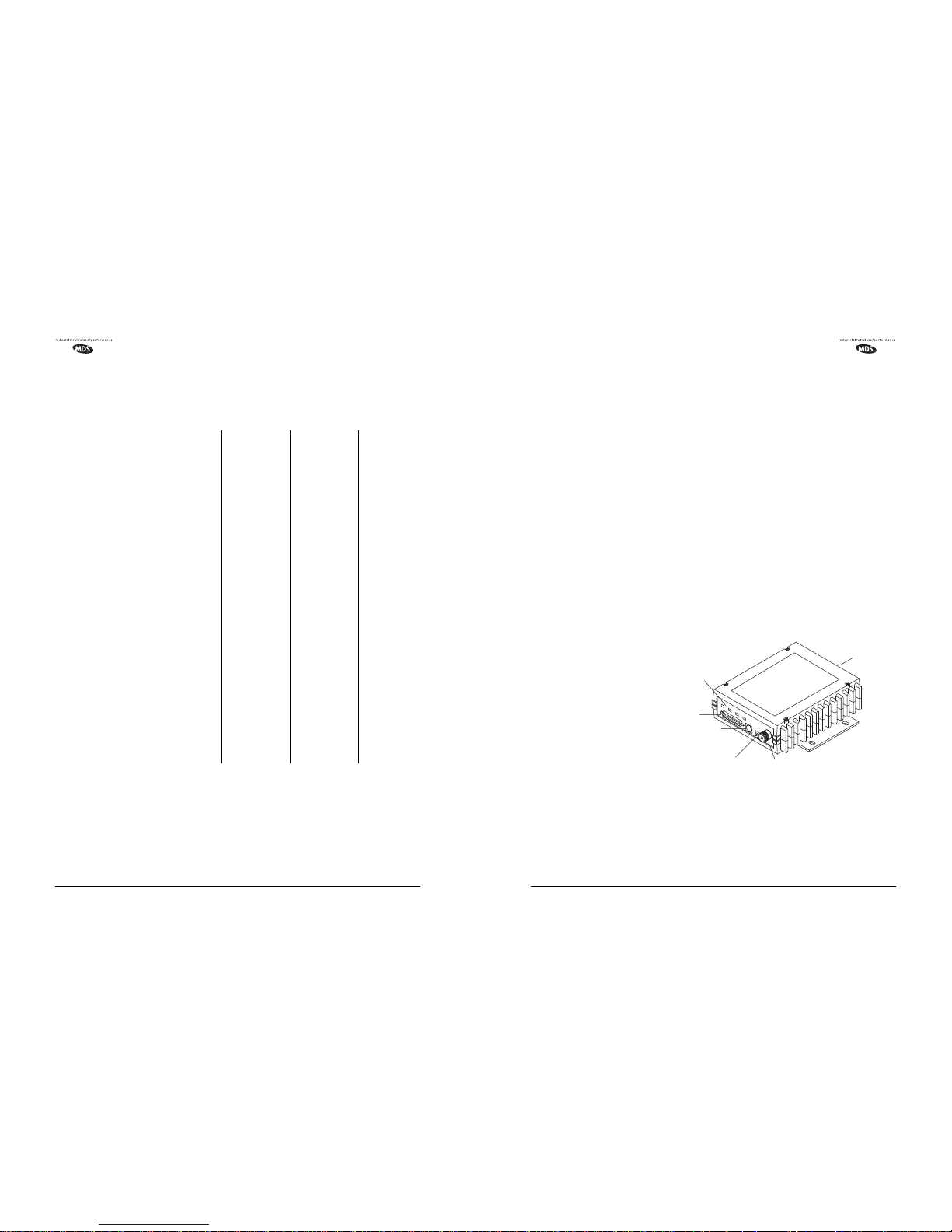
Figure 1. Transceiver Connectors and Indicators
The transceiver is designed for trouble-free operation with data equipment provided by many other manufacturers, including Remote Terminal Units (RTUs), programmable logic controllers (PLCs), flow
computers, lottery terminals, automatic teller machines, and others.
EXTERNAL
INTERFACE
CONNECTOR
(DB-25)
DIAGNOSTICS
CONNECTOR (RJ-11)
13.8 VDC POWER
CONNECTOR
ANTENNA CONNECTOR
(TYPE “N”)
SERIAL NUMBER
LABEL
LED INDICATORS (4)
 Loading...