

Microwave Data Systems iNet 900 Quick Start Manual
MDS iNet 900
™
Wireless IP/Ethernet Transceiver
MDS 05-2873A01, REV. FCC
AUGUST 2001

Z?
DRAFT 6—8/30/01
QUICK START GUIDE
Below are the basic steps for installing the MDS iNet 900 transceiver. Detailed instructions are given in
the Section 3.0, INSTALLATION PLANNING , on page 5 of this manual.
1. Install and connect the antenna system to the radio
• Use good quality, low-loss coaxial cable. Keep the feedline as short as possible.
• Preset directional antennas in the direction of desired transmission/reception.
2. Apply DC power to the radio (13.8 Vdc @ 500 mA)
• Connect a DC power source to the i Net’s power connector.(Negative ground only.)
• Observe proper polarity when connecting the DC cable. See Figure 10 on page 16.
3. Review the initial configuration profile
• Connect a computer with HTTP browser to the LAN port, or a terminal to the COM1 port, to identify,
and revise if necessary the MDS i Net 900’s primary operating parameters. (See “Step 5—Review
the Radio’s Configuration” on page 16 for details.)
✓
Operating Mode: Access Point (Master) or Station Adaptor (Remote)
✓
Internet Protocol (IP) Address
Network Name
✓
✓
Time and Date—If event logging is enabled
1
4. Verify proper operation of the MDS i Net radio-modem
• See Table 2 on page 7 for an explanation of the LED status indicators.
• Refine the antenna heading for maximum received signal strength using the radio signal strength
indicator (
) function found on the browser’s home page. The RSSI display will be in dBm.
RSSI
5. Connect the user’s equipment to the MDS i Net’s LAN, COM1or COM2 ports
• LAN—Use a RJ-45 Ethernet connector/cable.
• COM2—Recommended for serial-based data equipment.
Use a DB-9 female connector. Interface is RS-232/EIA-232 compatible.
• COM1—Reserve, if practical, for use to connect terminal for unit configuration.
Use a DB-9 male connector. Interface is RS-232/EIA-232 compatible.
(See Table 9 on page 34 for pin descriptions and Figure 9 on page 16 for port defaults.)
6. Verify proper operation of the user’s equipment
• A properly configured system will work exactly as it would if the data equipment were communicating
through a conventional wired system. (See Table 4.6 on page 18)
• The LINK LED will blink intermittently under normal operation if it connects with another
MDS iNet 900 transceiver.
• Use the IP “PING” command to verify the Access Point can be contacted by the Station Adapter.
1. While this may be of value, the time and date setting does not seem like a primary parameter and is
beyond the scope of this draft.

DRAFT 6—8/30/01

DRAFT 6—8/29/01
TABLE OF CONTENTS
1.0 ABOUT THIS MANUAL................................................................1
2.0 PRODUCT DESCRIPTION .........................................................1
2.1 Transceiver Features ........................................................................2
2.2 Spread Spectrum Radios—
How Are They Different? ..........................................................................3
2.3 Typical Applications ..........................................................................3
Wireless IP/Ethernet LAN Connectivity ..........................................3
Point-to-Point System .....................................................................3
Dealing with difficult terrain.............................................................4
2.4 Accessories ......................................................................................4
3.0 INSTALLATION PLANNING.........................................................5
3.1 General Requirements .....................................................................5
3.2 Site Selection ...................................................................................6
Terrain and Signal Strength............................................................6
Conducting a Site Survey...............................................................7
3.3 A Word About Radio Interference ....................................................8
3.4 Antenna & Feedline Selection ..........................................................9
Antennas ........................................................................................9
Feedlines......................................................................................11
3.5 How Much Output Power Can be Used? .......................................11
Calculating System Gain ..............................................................12
4.0 INSTALLATION..........................................................................13
4.1 Step 1— Mounting the Transceiver ................................................13
4.2 Step 2—Install the Antenna and Feedline ......................................15
4.3 Step 3—Connect the Data Equipment ...........................................15
4.4 Step 4—Measure & Install Primary Power .....................................16
4.5 Step 5—Review the Radio’s Configuration ....................................16
Procedure.....................................................................................17
4.6 Step 6—Connect the User Data Equipment ..................................18
4.7 Step 7—Check for Normal Operation ............................................18
Procedure.....................................................................................18
4.8 Performance Optimization ..............................................................19
Antenna Aiming ............................................................................19
Antenna SWR Check (Z? Major revision needed?)......................20
5.0 TRADITIONAL REPEA TER CONFIGURA TION WITH TWO RADIOS
20
MDS 05-2873A01, Rev. A MDS i Net 900 Installation and Operation Guide i
5.1 Overview ........................................................................................20

DRAFT 6—8/29/01
5.2 Antennas ........................................................................................21
5.3 Network Name ...............................................................................21
5.4 Interface Wiring ..............................................................................21
6.0 PROGRAMMING.......................................................................21
6.1 Programming Via an HTTP/Web Browser ......................................22
Making the Connection.................................................................22
Start-up Screen ............................................................................22
System Configuration Screen.......................................................23
Radio/Modem Screen Z?..............................................................23
6.2 Programming Via COM1 Port & a Terminal Program .....................24
Making the Connection.................................................................24
Communicating with the iNet transceiver .....................................24
Using the Menu-Based Management Toolbox..............................24
Review and Changing Essential Parameters................................26
7.0 TROUBLESHOOTING...............................................................26
7.1 LED Indicators ................................................................................27
7.2 Troubleshooting Chart ....................................................................27
8.0 REPEATER ASSITED LANS.....................................................28
Repeater Systems........................................................................28
Option 1—Traditional with two-radio repeater ..............................28
Option 2—With Store-and-Forward Station..................................29
9.0 TECHNICAL REFERENCE.......................................................30
9.1 Technical Specifications .................................................................30
9.2 Data Interface Connectors—
LAN, COM1 & DATA Ports .....................................................................32
LAN (Local Area Network) Port—RJ-45 Ethernet Interface..........32
COM1 Port ...................................................................................33
COM2 Port....................................................................................34
9.3 Table-Top Test Setup ......................................................................34
9.4 Using a Personal Computer to Configure the iNet Radio ...............35
Connecting a PC to iNet’s LAN (Ethernet) Port............................35
Connecting a PC to iNet’s COM1 Port..........................................35
10.0 GLOSSARY OF TERMS..........................................................36
Copyright Notice
This Installation and Operation Guide and all software described herein
are protected by copyright. Copyright 2001, Microwave Data Systems,
Inc. All rights reserved.
ii MDS i Net 900 Installation Guide MDS 05-2873A01, Rev. A
10.1 dBm-Watts-Volts Conversion Chart ..............................................39

DRAFT 6—8/29/01
Serviceability of this Manual
While every reasonable effort has been made to ensure the accuracy of
this manual, product improvements may result in minor differences
between the manual and the product shipped to you. If you have additional questions or need an exact specification for a product, please contact our Customer Service Team using the information at the back of this
guide. Microwave Data Systems Incorporated reserves its right to correct any errors and omissions. Updated information may also be available on our Web site at www.microwavedata.com.
Operational Safety Notices
RF Exposure
The radio equipment described in this guide emits radio frequency
energy. Although the power level is low, the concentrated energy from
a directional antenna may pose a health hazard. Do not allow people to
come within two meters (6 feet) of the antenna when the transmitter is
operating.
This manual is intended to guide a professional installer in installing,
operating and performing basic system maintenance on the described
equipment.
FM/UL/CSA Notice
MDS iNet 900 When Approved
This product is available for use in Class I, Division 2, Groups A, B,
C & D Hazardous Locations. Such locations are defined in Article 500
of the National Fire Protection Association (NFPA) publication NFPA
70, otherwise known as the National Electrical Code.
The transceiver has been recognized for use in these hazardous locations
by three independent agencies —Underwriters Laboratories (UL), Factory Mutual Research Corporation (FMRC) and the Canadian Standards
Association (CSA). The UL certification for the transceiver is as a Recognized Component for use in these hazardous locations, in accordance
with UL Standard 1604. The FMRC Approval is in accordance with
FMRC Standard 3611. The CSA Certification is in accordance with
CSA STD C22.2 No. 213-M1987.
FM/UL/CSA Conditions of Approval
MDS iNet 900 When Approved
The transceiver is not acceptable as a stand-alone unit for use in the hazardous locations described above. It must either be mounted within
another piece of equipment which is certified for hazardous locations, or
installed within guidelines, or conditions of approval, as set forth by the
approving agencies. These conditions of approval are as follows:
1. The transceiver must be mounted within a separate enclosure which
MDS 05-2873A01, Rev. A MDS i Net 900 Installation and Operation Guide iii
is suitable for the intended application.

DRAFT 6—8/29/01
2. The antenna feedline, DC power cable and interface cable must be
routed through conduit in accordance with the National Electrical
Code.
3. Installation, operation and maintenance of the transceiver should be
in accordance with the transceiver's installation manual, and the
National Electrical Code.
4. Tampering or replacement with non-factory components may
adversely affect the safe use of the transceiver in hazardous locations, and may void the approval.
5. When installed in a Class I, Div. 2, Groups A, B, C or D hazardous
location, observe the following:
Do not disconnect equipment unless power has been
switched off or the area is know to be non-hazardous.
EXPLOSION
HAZARD
Refer to Articles 500 through 502 of the National Electrical
Code (NFPA 70) for further information on hazardous loca-
tions and approved Division 2 wiring methods.
1
Z?
FCC Notice, U.S.A.
MDS i Net 900 When Approved
The MDS iNet 900 transceivers comply with Part 15 of the FCC Rules.
Operation is subject to the following two conditions: (1) this device may
not cause harmful interference, and (2) this device must accept any
interference received, including interference that may cause undesired
operation.
This device is specifically designed to be used under Section 15.247 of
the FCC Rules and Regulations. Any unauthorized modification or
changes to this device without the express approval of Microwave Data
Systems may void the user’s authority to operate this device.
Furthermore, this device is indented to be used only when installed in
accordance with the instructions outlined in this manual. Failure to
comply with these instructions may also void the user’s authority to
operate this device.
FCC Information
This equipment has been tested and found to comply with the limits for
a Class A digital device, pursuant to Part 15 of the FCC Rules. These
limits are designed to provide reasonable protection against harmful
interference when the equipment is operated in a commercial environ-
iv MDS i Net 900 Installation Guide MDS 05-2873A01, Rev. A
1. This seem like this note should be a DANGER classification if there is a
potential for an explosion. Please verify.

DRAFT 6—8/29/01
ment. This equipment generates, uses, and can radiate radio frequency
energy and, if not installed and used in accordance with the instruction
manual, may cause harmful interference to radio communications.
Operation of this equipment in a residential area is likely to cause
harmful interference in which case the user will be required to correct
the interference at his own expense.
MDS 05-2873A01, Rev. A MDS i Net 900 Installation and Operation Guide v

DRAFT 6—8/29/01
1.0 ABOUT THIS MANUAL
This guide presents installation and basic operating instructions for the
MDS i Net 900™ transceiver. Following installation, we suggest
keeping this guide near the equipment for future reference.
The terms Access Point and Station Adapter are abbreviated as “
and “
manual wherever space is at a premium.
This manual does not cover all possible MDS iNet 900 user-controllable
parameters and/or diagnostic tools. For an in-depth description of all of
the features and controls of the MDS iNet 900, please read the
MDS iNet Network Manager’s Manual
in various technical illustrations and tables used in this
S.A.”
, P/N 05-xxxxA01.
A.P.”
2.0 PRODUCT DESCRIPTION
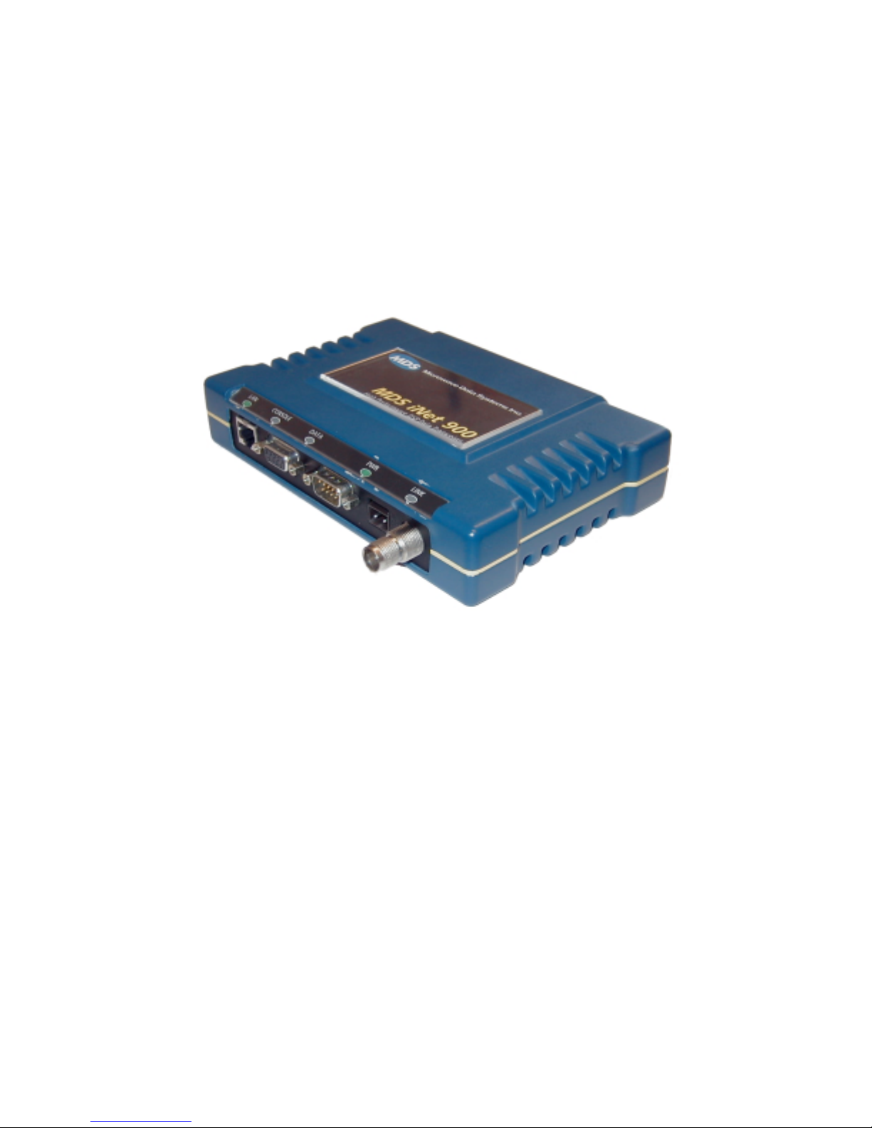
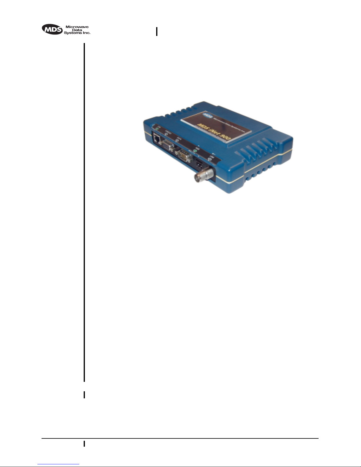
The MDS i Net 900 transceiver, shown in Figure 1, is designed to provide network managers with a easy-to-install wireless local area network (LAN) services with plug-and-play hardware. For basic services,
just hook up an antenna, connect your Ethernet LAN to the radio’s LAN
port, apply primary power, and you are done. And, no license is
required.
The transceiver is a spread-spectrum radio designed for operation in the
license-free 900 MHz frequency band. The MDS iNet 900 provides reliable communications up to distances of 30 miles (50 km), even in the
presence of weak signals or interference.
Only two user-controllable parameters need to be checked at the time of
installation—the radio’s Access Point/Station Adapter operating mode,
and “network name” of the unit.
The MDS iNet 900 transceiver is based on the IEEE 802.11 wireless
LAN specification. From this perspective, iNet transceivers serve as
“Access Points” and “Station Adapters”. An Access Point is a wireless
hub that provides connectivity into a wired Ethernet LAN. This connectivity is achieved through remote Station Adapters. From a radio perspective, an Access Point also works as a “master station” providing
synchronization signaling for the remote radios (Access Point units).
A Station Adapter provides wireless connectivity to and Access Point to
one or more Ethernet devices connected to its local interface. From a
radio perspective, the Station Adapter also works as a remote radio that
communicates to a master radio (Access Point).
MDS 05-2873A01, Rev. A MDS i Net 900 Installation and Operation Guide 1
DRAFT 6—8/29/01
Users with a mixture of equipment with Ethernet and serial data interfaces can choose to use one of the two user-configurable serial ports.
This flexibility allows the iNet transceiver to provide services in data
networks that are on a path from legacy serial/EIA/RS-232-based hardware to the faster and more easily interfaced Ethernet world. The radio
and data interfaces are easily arranged via the
(Ethernet) port using HTTP.
COM1
port or via the
LAN
Figure 1. The MDS iNet 900 Transceiver
The transceiver is housed in a compact and rugged cast-aluminum case
that needs only be protected from direct exposure to the weather. It contains a single printed circuit board with all necessary components for
radio operation and data communications.
2.1 Transceiver Features
Listed below are several key features of the MDS i Net 900 transceivers.
These are designed to ease the installation and configuration of the
radio, while retaining the ability to make changes in the future.
• Plug-and-Play Connectivity—Ethernet bridge configuration
option requires virtually no setup
• High Speed—512 kbps is 50-times faster than 9.6 kbps radios
• Long Range—30 miles (50 km) in wireless LAN configuration
• Robust Radio Communications—Designed to operate in
high-interference environments
• Industrial-Grade Product—Extended temperature range for
trouble-free operation in extreme environments
• Serial Ports—IP gateway to legacy serial interface based equipment
• Same hardware for Access Point and Station Adaptor configurations
2 MDS i Net 900 Installation Guide MDS 05-2873A01, Rev. A
DRAFT 6—8/29/01
2.2 Spread Spectrum Radios—
How Are They Different?
The main difference between a traditional (licensed) radio system and
the i Net transceivers is that these units “hop” from channel to channel
many times per second using a specific hop pattern applied to all radios
in the network. A distinct hopping pattern is provided for each of the
network name, thereby minimizing the chance of interference with other
spread spectrum systems. In the USA, and certain other countries, no
license is required to install and operate this type of radio system.
2.3 Typical Applications
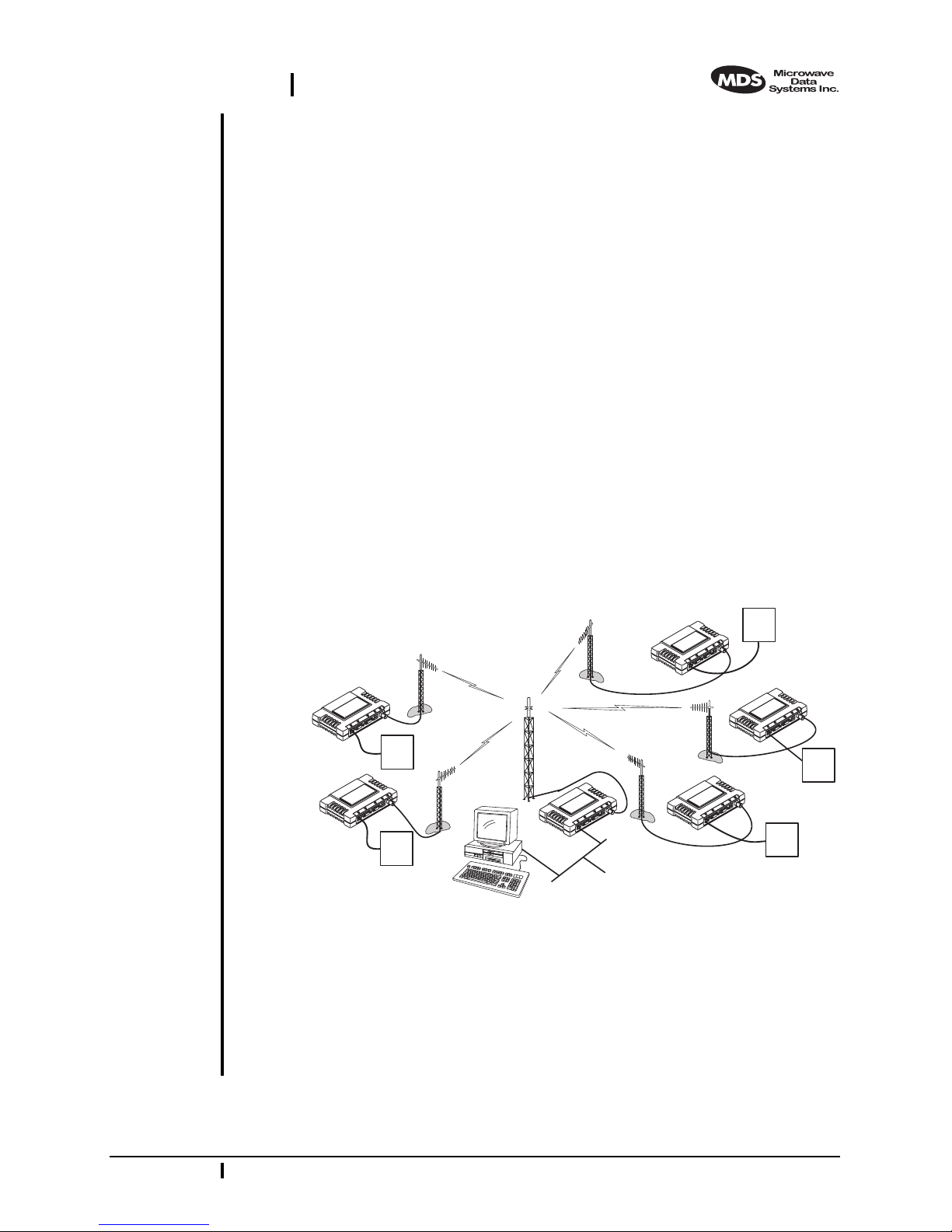
Wireless IP/Ethernet LAN Connectivity
This is the most common application of the MDS i Net 900 transceiver.
It consists of a central control station (Access Point) and one or more
associated Station Adapter units, as shown in Figure 2. A LAN provides
communications between a central host computer and remote terminal
units (RTUs) or other data collection devices. The operation of the radio
system is transparent to the computer equipment with the Access Point
station serving as the gateway to the WAN or host computer.
Invisible place holder
iNet S.A.
iNet S.A.
RTU
RTU
iNet S.A.
iNet S.A.
iNet A.P.
HOST
COMPUTER
Figure 2. Typical wireless LAN
RTU
iNet S.A.
RTU
RTU
Point-to-Point System
A point-to-point configuration (Figure 3) is a simple arrangement consisting of just two radios—a Access Point and a Station Adapter. This
provides communications link for the transfer of data between two locations.
MDS 05-2873A01, Rev. A MDS i Net 900 Installation and Operation Guide 3

DRAFT 6—8/29/01
Invisible place holder
RTU
HOST
COMPUTER
Figure 3. Typical point-to-point link
(A LAN connection may be used in place of a Host Computer)
Dealing with difficult terrain
In some geographical areas there may be obstacles that make communication between iNet transceivers difficult. These obstacles commonly
are large buildings, natural geological formations or dense foliage.
These obstacles can often be overcome with a repeater station. See
“REPEATER ASSITED LANS” on page 28 for descriptions of basic
repeater configurations.
iNet A.P. iNet S.A.
2.4 Accessories
The MDS iNet 900 transceiver can be used with one or more of the
accessories listed in Table 1. Contact the factory for ordering details.
Table 1. Accessories
Accessory Description MDS P/N
A/C Power
Adapter
LAN Antenna Small and flexible 1/4 wavelength antenna
TNC to N
Adapter
Ethernet RJ-45
Cross-over
Cable
Flat-Surface
Mounting
Brackets
19˝ Rail
Mounting
Brackets
A small switching power supply module
designed for continuous service. UL approved.
Output 13.8 Vdc @ 500 mA.s
plugged directly into the radio’s ANTENNA
port. Suitable for short-range local area
networks.
Short length of coaxial cable (6”/15 cm) used to
connect the radio’s TNC antenna connector to
a Type N commonly used on large diameter
coaxial cables.
Cable assembly used to cross-connect the
Ethernet ports of two iNet radios used in a
repeater configuration. (Cable length = 3’/1M)
Brackets: 2” x 3” plates designed to be screwed
onto the bottom of the transceiver for
surface-mounting the radio.
Screws: 6-32/1/4˝ with locking adhesive.
(Industry Standard MS 51957-26)
Adaptor for mounting one MDS iNet 900 radio
in a standard 19-inch equipment rack.
03-xxxxA01
03-xxxxA01
03-xxxxA01
03-xxxxA01
82-1753-A01
70-2620-A01
03-xxxxA01
4 MDS i Net 900 Installation Guide MDS 05-2873A01, Rev. A
DRAFT 6—8/29/01
DIN Rail
Mounting
Brackets
Short-Range
Antenna
Table 1. Accessories
Adaptor for mounting one MDS iNet 900 radio
in a DIN standard equipment rack.
Short 1/2-wave antenna. Mounts directly onto
the radio’s coaxial connector. Suitable only for
short-range LANs, such as within a building or
small campus.
(Continued)
03-xxxxA01
03-xxxxA01
3.0 INSTALLATION PLANNING
The installation of the radio is not difficult, but it does require some
planning to ensure station reliability and efficiency. This section provides tips for selecting an appropriate site, choosing an antenna system,
and reducing the chance of harmful interference.
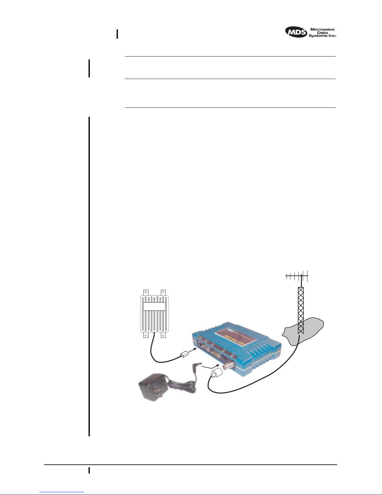
3.1 General Requirements
There are three main requirements for installing the radio—adequate
and stable primary power, a good antenna system, and the correct interface between the transceiver and the data device.
Figure 4 shows a typical Station Adapter installation. An external directional antenna is normally used and an RTU/PLC is connected to one of
the serial ports (COM1/COM2). 13.8 Vdc is supplied to the Station
Adapter by an external source.
Invisible place holder
ANTENNA
SYSTEM
REMOTE
TERMINAL
UNIT
LAN PORT
POWER SUPPLY
13.6 VDC @
500 mA (MIN.)
Figure 4. Typical Station Adapter arrangement
(RTU can be connected to any compatible LAN or COM Port)
iNet RADIO
TRANSCEIVER
LOW-LOSS FEEDLINE
MDS 05-2873A01, Rev. A MDS i Net 900 Installation and Operation Guide 5

DRAFT 6—8/29/01
3.2 Site Selection
For a successful installation, careful thought must be given to selecting
proper sites for the Access Points and Station Adapters. Suitable sites
should provide:
• Protection from direct weather exposure
• A source of adequate and stable primary power
• Suitable entrances for antenna, interface or other required
cabling
• Antenna location that provides an unobstructed transmission
path in the direction of the associated station
These requirements can be quickly determined in most cases. A possible
exception is the last item—verifying that an unobstructed transmission
path exists. Radio signals travel primarily by line-of-sight, and obstructions between the sending and receiving stations will affect system performance. If you are not familiar with the effects of terrain and other
obstructions on radio transmission, the discussion below will provide
helpful background.
(s)
Terrain and Signal Strength
While the 900 MHz band offers many advantages over VHF and lower
UHF frequencies for data transmission, the band is more prone to signal
attenuation from obstructions such as terrain, foliage or buildings in the
transmission path.
A line-of-sight transmission path between the central Access Point station and its associated remote access station site
is highly desirable
(s)
and provides the most reliable communications link. A line-of-sight
path can often be achieved by mounting the station antenna on a tower
or other elevated structure that raises it to a level sufficient to clear surrounding terrain and other obstructions.
The importance of a clear transmission path relates closely to the distance to be covered by the system. If the system is to cover only a limited
geographic area, say up to 3 miles (4.8 km), then some obstructions in
the transmission path can usually be tolerated with minimal impact. For
longer range systems, any substantial obstruction in the transmission
path could compromise the performance of the system, or block transmission entirely.
Much depends on the minimum signal strength that can be tolerated in
a given system. Although the exact figure will differ from one system to
another, a Received Signal Strength Indication (RSSI) of –80 dBm or
stronger will provide acceptable performance in many systems. While
the equipment will work at lower signal strengths, this provides a “fade
6 MDS iNet 900 Installation Guide MDS 05-2873A01, Rev. A

DRAFT 6—8/29/01
margin” to account for variations in signal strength which may occur
from time-to-time. RSSI can be measured with a terminal connected to
COM1
the
Port or with a HTTP browser to the
(See Section 4.6 on page 18 for details.)
Conducting a Site Survey
If you are in doubt about the suitability of the radio sites in your system,
it is best to evaluate them before a permanent installation is begun. This
can be done with an on-the-air test (preferred method); or indirectly,
using path-study software.
An on-the-air test is preferred because it allows you to see firsthand the
factors involved at an installation site and to directly observe the quality
of system operation. Even if a computer path study was conducted earlier, this test should be done to verify the predicted results.
The test can be performed by first installing a radio and antenna at the
proposed Access Point station site and then visiting each Station
Adapter site with a transceiver and a hand-held antenna. (A PC with a
network adapter can be connected to each radio in the network to simulate data during this test using the PING command.)
LAN (Ethernet) connector.
With the hand-held antenna positioned near the proposed mounting
spot, a technician can check for synchronization with the Access Point
station (shown by a lit
LINK LED on the front panel) and measure the
reported RSSI value. (See Section 4.6 on page 18 for details.) If adequate signal strength cannot be obtained, it may be necessary to mount
the station antennas higher, use higher gain antennas, select a different
site or consider installing a repeater station. To prepare the equipment
for an on-the-air test, follow the general installation procedures given in
this guide and become familiar with the operating instructions found in
Section 4.0 on page 13.
If time is short, and a site survey is impractical, a computer path study
is a good alternative. Factors such as terrain, distance, transmitter
power, receiver sensitivity, and other conditions are taken into account
to predict the performance of a proposed system. Contact MDS for more
information on path study services.
Table 2.iNet Front Panel LED Functions
LED Label Activity Indication
LAN ON Link integrity OK
Blinking Data TX/RX
OFF LAN not detected
COM1
(Console)
ON Not Defined
Blinking Data TX/RX
OFF No data detected
MDS 05-2873A01, Rev. A MDS iNet 900 Installation and Operation Guide 7
 Loading...