

Microvideo Synergy SY800, Synergy SY810 Instruction Manual

1

Installation and Programming Manual
“SYNERGY” Copyright © 2012 Microvideo - http://www.microvideo.eu
For more information, updates, requests, please visit www.microvideo.eu, the official
website of Microvideo Company, specialized in Design, Manufacture and Distribution of
advanced Intrusion Systems.
DISCLAIMER
Every care has been taken in the creation, implementation, verification of this literature,
however, neither the author nor Microvideo Srl, can accept any responsibility for the accuracy of the information described nor provide any guarantee on the performance or results
obtained. The same applies to any person or company involved in the creation, production,
and distribution of this documentation.
Names and marks mentioned in this document are trademarks of their respective owners
"SYNERGY" Microvideo Copyright © 2012 - http://www.microvideo.eu
2
Installer Manual Microvideo srl www.microvideo.eu

Table of Contents
Warranty .................................................................................................................................................... 5
Limitation of Liability .................................................................................................................................. 5
Copyright ................................................................................................................................................... 5
CHAPTER 1 - Introduction................................................................................................................................ 6
Chapter 2 –Modules Description ....................................................................................................................... 7
Control Panel ................................................................................................................................................. 7
Keyboard (Mod. SY820) ................................................................................................................................ 9
LED .............................................................................................................................................................. 10
DISPLAY ...................................................................................................................................................... 10
DIRECTIONAL KEYS .................................................................................................................................. 10
INTEGRATED PROXIMITY READER ......................................................................................................... 10
NUMERIC KEYPAD .................................................................................................................................... 10
DELETE BUTTON ........................................................................................................................................ 11
ESC KEY ...................................................................................................................................................... 11
MACRO FUNCTION KEYS .......................................................................................................................... 11
GSM / GPRS Module (Mod. SY860) ............................................................................................................ 11
Expansion Module (Mod. SY840) ............................................................................................................... 12
Inserter Jack Module (Mod. SY825) ............................................................................................................ 13
Wall Inserter Module (Mod. SY826) ............................................................................................................ 13
LAN Module (Mod. SY881) ......................................................................................................................... 14
BUS Splitter (Mod. SY930) ......................................................................................................................... 14
DVR WALL 4N-8N ....................................................................................................................................... 15
Radio Receiver Module (mod. SY910) ........................................................................................................ 16
Radio Magnetic Contact Module (mod. SY920) ......................................................................................... 16
MAGNET + NC Configuration ................................................................................................................. 17
NC + NC Configuration ........................................................................................................................... 17
Configuration Magnet + Blinds ................................................................................................................ 18
Supervision Function .............................................................................................................................. 18
Report Open/Close Magnet/NC .............................................................................................................. 18
Inertial Radio Module (mod. SY921) ....................................................................................................... 18
Supervision Function .............................................................................................................................. 19
Motion Sensor Module (mod. SY925) ......................................................................................................... 20
Radio Remote Control (mod. SY915) ......................................................................................................... 21
Procedure for Inserting Through Key ...................................................................................................... 22
CHAPTER 3 – Installing ................................................................................................................................. 23
Installing Control Panel ............................................................................................................................... 23
Connection of Voice Module (Mod. SY-900) ........................................................................................... 23
Connecting siren to an output ................................................................................................................. 24
Sample connection of open collector outputs ......................................................................................... 24
Connecting Sensor Alarm to Zones ........................................................................................................ 25
Modules Installing on CAN BUS.................................................................................................................. 28
Keyboard Module SY920 Installation .......................................................................................................... 28
Installing the Expansion Module SY840-SY841-SY845 ............................................................................ 29
Installing GSM/GPRS SY860-SY861 Module ............................................................................................ 30
Installing LAN SY880-SY881 module ......................................................................................................... 31
Wall Installing of inserter SY826Module ...................................................................................................... 32
Installing the SY825 inserter Jack Module .................................................................................................. 33
Installing the SY930 Bus Isolator / Repeater Module ................................................................................. 33
Installing Radio SY920-SY921 Modules ..................................................................................................... 35
Installing SY925 Motion Sensor Module ..................................................................................................... 36
Configuring Module Address ....................................................................................................................... 37
Addressing Module Keyboards ........................................................................................................... 37
Addressing Expansion Module ........................................................................................................... 38
Addressing GSM / GPRS Module ...................................................................................................... 38
Testing System ............................................................................................................................................ 39
CHAPTER 4– Programming Control Panel ..................................................................................................... 40
Installer Menu .............................................................................................................................................. 40
General Parameters ................................................................................................................................ 40
ZONES .................................................................................................................................................... 42
RADIO ZONES ....................................................................................................................................... 43
3
Installer Manual Microvideo srl www.microvideo.eu

Outputs .................................................................................................................................................... 43
AND Zones .............................................................................................................................................. 44
Expansions .............................................................................................................................................. 44
Areas ....................................................................................................................................................... 44
Timer ....................................................................................................................................................... 45
Keyboards ............................................................................................................................................... 45
RFID Keys ............................................................................................................................................... 46
Readers ................................................................................................................................................... 46
WALL Modules ........................................................................................................................................ 46
Fog modules ........................................................................................................................................... 47
Radio Receivers ...................................................................................................................................... 47
Radio Modules ........................................................................................................................................ 48
Radio Remote Controls ........................................................................................................................... 48
Procedure of Remote Control Learning .................................................................................................. 48
User Code ............................................................................................................................................... 49
Installer Codes ........................................................................................................................................ 49
Macro ...................................................................................................................................................... 49
Actions .................................................................................................................................................... 50
Events ..................................................................................................................................................... 50
Address Book .......................................................................................................................................... 52
Vocal Messages ...................................................................................................................................... 52
GSM Transmission .................................................................................................................................. 52
LAN ..................................................................................................................................................... 53
Holidays .................................................................................................................................................. 53
Alarm Management ................................................................................................................................. 54
System Management .............................................................................................................................. 54
CHAPTER 5 – Plant Management by GSM/GPRS Module ........................................................................... 55
Incoming Calls and SMS. ............................................................................................................................ 55
Voice Menu .................................................................................................................................................. 55
SMS commands .......................................................................................................................................... 56
APPENDIX B – Phisic Terminals – SY800/SY810 .......................................................................................... 59
Zones (Inputs) ............................................................................................................................................. 59
APPENDIX B – Phisic Terminals – ST-SMOKE .............................................................................................. 61
Zones (Inputs) ............................................................................................................................................. 61
Output .......................................................................................................................................................... 61
Appendix C –Deafault Reset Procedure .......................................................................................................... 63
Appendix D –Vocal Messages ......................................................................................................................... 64
4
Installer Manual Microvideo srl www.microvideo.eu

CHAPTER 1 - Introduction
Warranty
Microvideo srl ensures that products are free from defects in materials and workmanship
for a period of 12 months from date of manufacture. Given that Microvideo srl does not
install directly the products mentioned here , and since these products can be used in
conjunction with products not manufactured by Microvideo , Microvideo srl can not
guarantee the performance of safety equipment . Obligation and liability of the seller is
limited to repairing or replacing, at its option, any product not meeting the specifications .
In no event Microvideo srl can be liable to the buyer or any other person for any loss or
damage, direct or indirect, consequential or incidental damages, including, without
limitation, any damages for lost profits, stolen goods, or claims by any other party caused
by defective goods or otherwise arising from the improper , incorrect or otherwise faulty
installation or use of these products.
The warranty covers only defects that result from the proper use of the product. It does not
cover :
• Misuse or negligence
• Damage caused by fire, flood, wind or lightning
• Vandalism
• Wear
Microvideo srl takes responsibility, at its option, for repairing or replacing any defective
product. Improper use, especially other than those specified in this manual, will nullify your
warranty. For more detailed informations about the warranty, refer to your dealer.
Microvideo srl is not responsible for any damage caused by improper use of the product.
5
Limitation of Liability
Installation and use of these products should be allowed only to authorized persons.
Specifically, the installation must strictly follow the instructions in this manual.
Copyright
The information contained in this document are the sole property of Microvideo srl. No
reproduction or modification is permitted without the prior permission of Microvideo s.r.l.
Tutti i diritti sono riservati.
Manual version: 1.02
Installer Manual Microvideo srl www.microvideo.eu
CHAPTER 1 - Introduction
CHAPTER 1 - Introduction
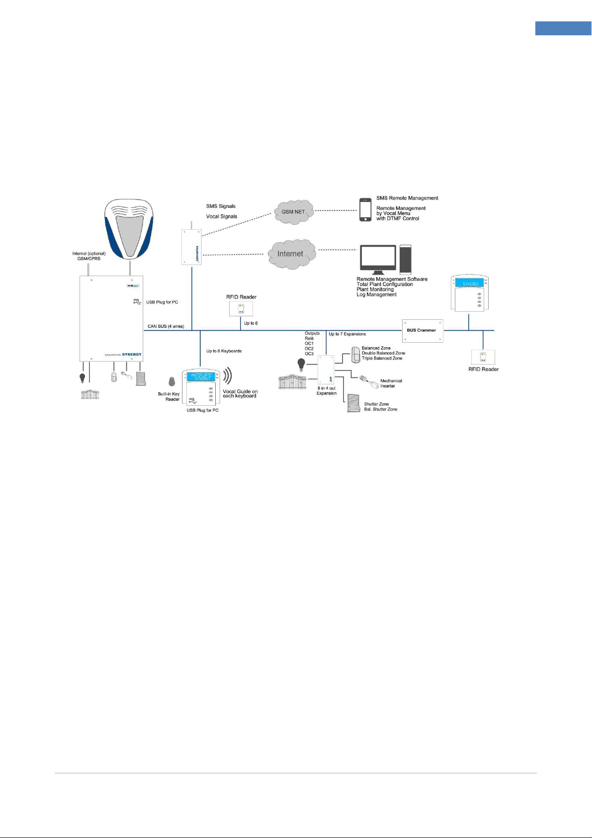
Security System SYNERGY
The SYNERGY Security System is a completely integrated and modular System, designed
to meet the security needs in most of the domestic and industrial installations. The
modular management allows to use and expand the features of the System according to
the customer's requirements.
6
Installer Manual
This installer manual contains informations needed for proper installation / programming
of a SYNERGY plant.
It 's important to read carefully the manual to understand all the concepts necessary for the
proper installation and to familiarize yourself with the functions of the System.
Usually this manual is provided only in electronic form (pdf format)
User Manual
The user manual contains all the informations required for the correct use of the System
by the user. It 's important that the installer could check the correct comprehension of the
manual by the customer.
Installer Manual Microvideo srl www.microvideo.eu
Chapter 2 –Modules Description
Specifications
SY800
SY810
Chapter 2 –Modules Description
Control Panel
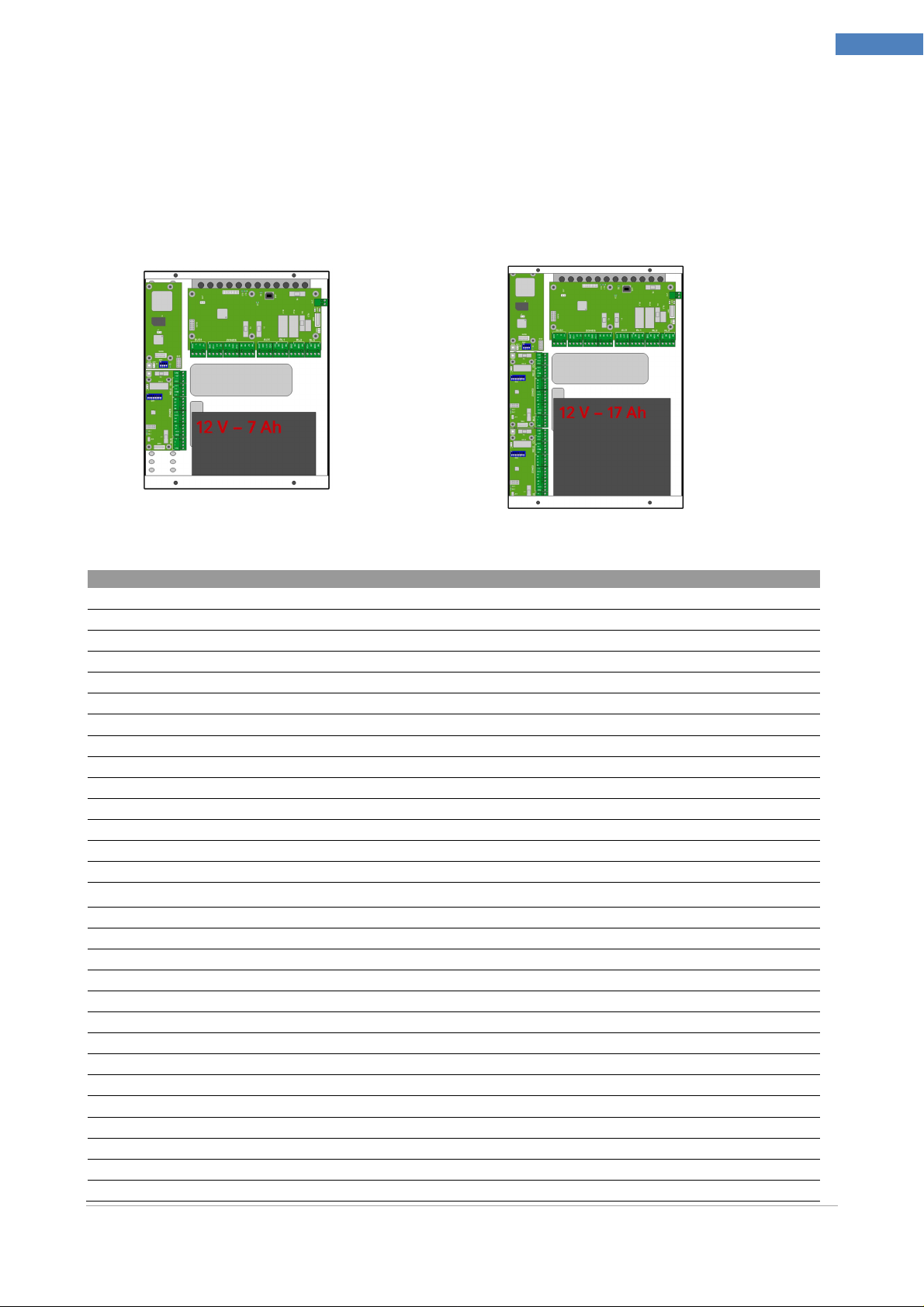
SYNERGY Control Panel is available in two models according to the features of the
System. There are also two box models, with the larger version you can insert a 17 Ah
battery and install up to three modules inside.
SY800 Control Panel
SY810 Control Panel
7
Inputs aboard 8
24h input 1
Programmable relays aboard 2
Areas managed by the system 8 12
Check the efficiency of battery Yes
Firmware upgrading of the central Yes
Firmware upgrading modules by central Yes
USB port (Programming) Yes
Removable Connectors Yes
GSM Aboard Yes (optional)
Module Expansion Board Yes
Keyboards 4 8
Expansions 7
Proximity Readers 4 8
GSM / GPRS 1
Dual Frequency Radio Receivers 2 4
Dual Frequency Radio Modules 10 64
Radio Areas 10 64
Installer Codes 2
User Code 16 64
Proximity Keys 8 64
Keys Equipment combinations 4 294 967 269
Dual Frequency Radio Remote Controls 4 32
Macro (all associated with timer) 18 36
Macro signaling Activation Event Yes
Macro Reset signaling event Yes
Actions 64
Configurable events 422
Weekly timer 25
Installer Manual Microvideo srl www.microvideo.eu
Features
SY800
SY810
SY810
managing Holidays 16 (periods)
Number of recordable events 2000
Supply Voltage 220V 220V
Maximum Power Consumption --- ---
Open Collector output current 50mA 50mA
Backup Battery 12V 7Ah. 12V 17Ah.
Power Pack 14V 2.6Ah. 14V 2.6Ah.
Container Size 270x330x85 270x380x105
Weight (without batteries) --- ---
Chapter 2 –Modules Description
8
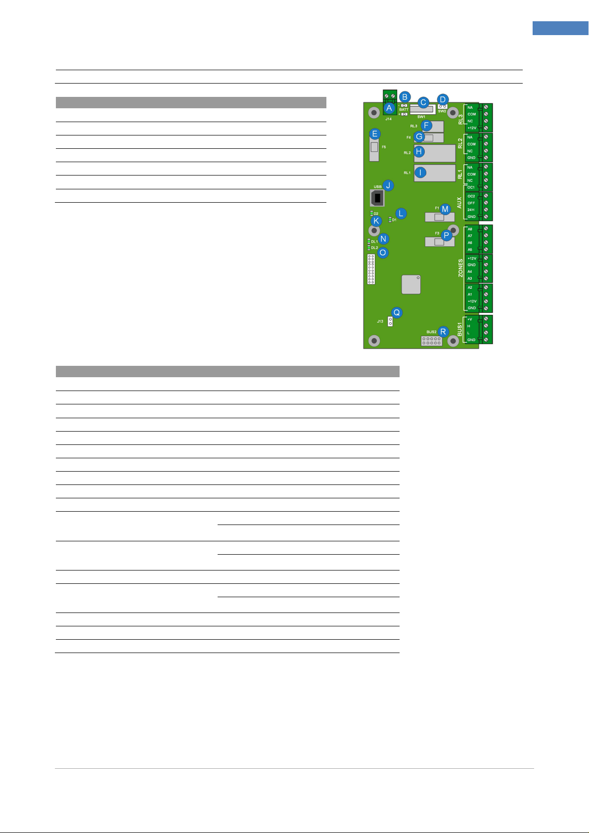
A Power supply connection terminals
B Battery Contacts
C tamper
D tamper Thornproof
E Fast acting fuse (2A) of +12 V power supply line protection
F Relay 3 (RL3) 0.5A - 24VDC
G Fast fuse (2A) of protection
H Relay 2 (RL2) 3A - 24VDC
I Relay 1 (RL1) 3A - 24VDC
J USB connector (Programming, Update FW Monitor)
K Link LED USB cable connection
ON: cable plugged
Off: Power cord not plugged in
L Link LED PC Connection
On: correct connection
Off: driver not recognized on PC
M F1: Fast acting fuse (2A) the protection of the +12 V INPUTS
N,O Alternate Flashing
Led STATE: correct operation
Off-fault
P Fast fuse (2A) of protection
Q Reset Factory setting (See Appendix C)
R Internal BUS connector (only for GSM / GPRS)
Link LED USB cable connection ON: cable plugged
Off: Power cord not plugged in
Link LED PC Connection On: correct connection
Off: driver not recognized on PC
Alternate Flashing Led STATE: correct operation
Off-fault
Installer Manual Microvideo srl www.microvideo.eu
Chapter 2 –Modules Description
Section
Conne
ctor SY810
SY820
SY820
RL3 NA,COM,NC Free connectors of the relay 3
+12V Power Connector 12V auxiliary
RL2 NA,COM,NC Free terminals of Relay 2
GND Power Supply Ground Connector
RL1 NA,COM,NC Relay 1 Free connectors
AUX OC1, OC2 Open Collector Connectors
OFF Terminal State System
24h 24h Input
GND Power Supply Ground Connector
ZONES A8, A7, A6, A5 Input connectors of the 5-6-7-8 areas
+12V, GND Auxiliary Power and Ground connectors
A4, A3, A2, A1 Input connectors of the 1-2-3-4 areas
+12V, GND Auxiliary Power and Ground Connectors
BUS1 +V, H, L, GND CAN Bus Connectors
Keyboard (Mod. SY820)
9
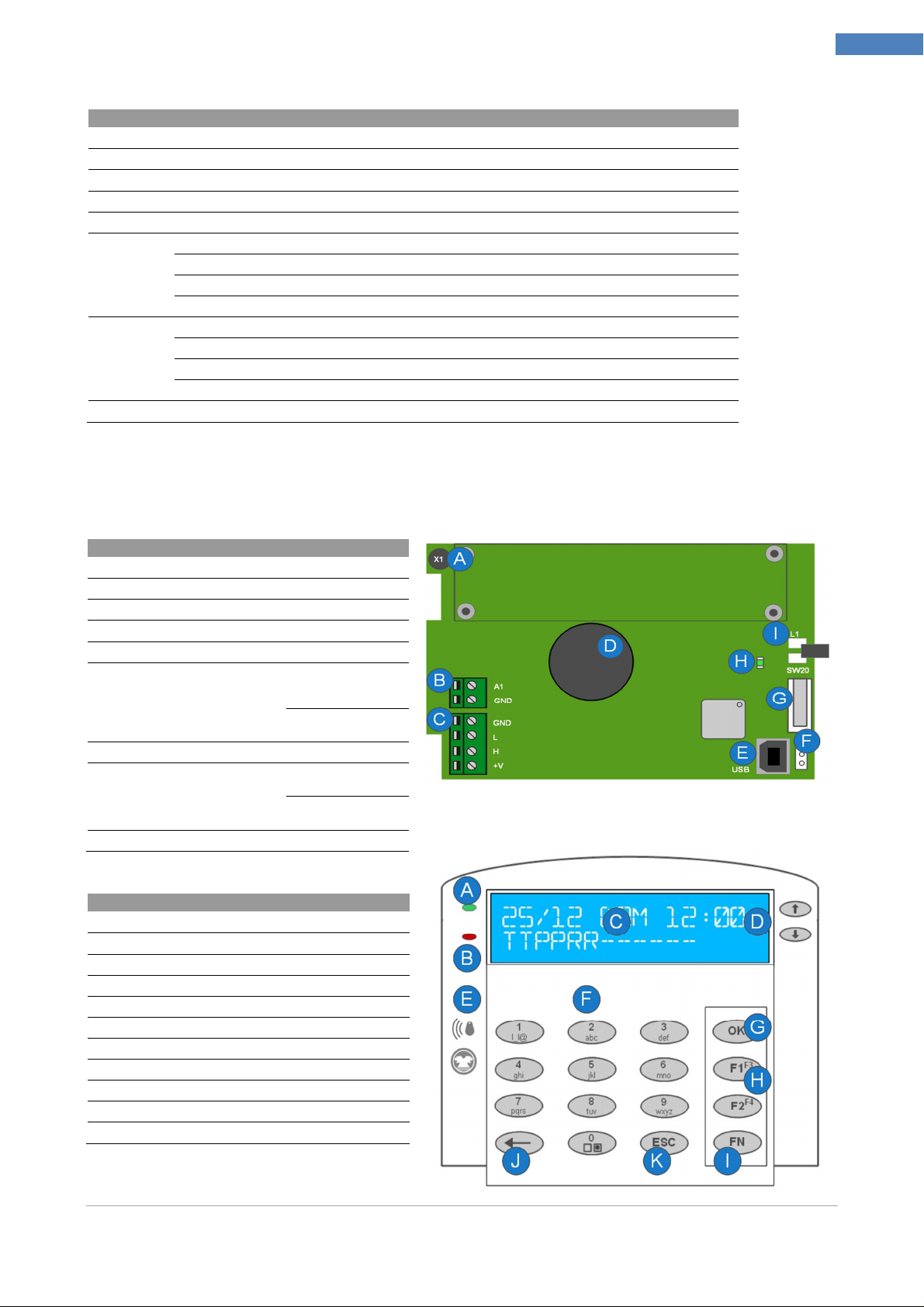
A Microphone capsule (Listening ambient)
B Input Connector A1
C Connector CAN Bus
D speaker
E USB connector (Programming, Log, Monitor Zone)
F Exclusion Tamper Snatch
Closed: EXCLUDED tamper
Open: tamper ENABLED
G Snatch connector
H Led Link USB On: USB
cable included
Off USB cable not
connected
I Proximity key reader
Exclusion Tamper
Snatch Closed:
EXCLUDED tamper
Open: tamper
ENABLED
Led Link USB On: USB
cable included
Off USB cable not
connected
A LED SIGNALS
B LED Status System
C Display
D Arrow keys to scroll through the menus
E Location Proximity Reader
F Numeric keypad for entering the parameters
G Ok button
H Macro keys (F1, F2, F3, F4)
I Function button to select F3 and F4 macro
J DEL key
K ESC key
Installer Manual Microvideo srl www.microvideo.eu

LED
Chapter 2 –Modules Description
Off Slow Flashing Fast Flashing On
10
Led SIGNALS
(red led)
Led STATE
(green led)
Proper operation of the
system
Disarmed At least one inserting open
Alarm Low 220 V network Diagnostics Alarm (Areas,
area
Tamper, Modules)
--- At least ona alarmed area
DISPLAY
The display is composed of two lines with large characters for a very easily reading.
The first line contains informations of the date, day of the week and time set in the system,
and the second line always indicate the status of all areas of the system.
Depending on the model of Control Panel, the first few characters of the second line
represent the areas and in every position a symbol indicates the status of the
corresponding area.
SY810 12 Areas managed by the system 12 characters representing areas Status
SY800 8 Areas managed by the system 8 characters representing areas Status
AREA STATUS Description
T TOTAL All The Zones associated to the area are armed
P PARTIAL At least one zone in the area was not armed
- NOT CONFIGURED The zone has NO area associated
R REST All areas
DIRECTIONAL KEYS
The directional keys allow you to scroll up and down menu appear in the display
The arrow keys are displayed on the keyboard macro .
If a valid code is entered, using the arrow keys you can scroll through the menu and
pressing ok you can access the menu / parameter selected
INTEGRATED PROXIMITY READER
The SY820 keyboard has a built-in proximity reader . Approaching the key on the left side
of the keyboard, next to the graphic indication , if the key is properly configured, it
activates the display on the 4 macro associated with the reader and the one macro
associated with the key. When you remove the key , the System runs the macro you see
on the display in that moment.
NUMERIC KEYPAD
Using the numeric keypad , you can enter the value of all the parameters and descriptions.
In addition, through the 0 button , you can select / deselect the areas of belonging in their
own menu.
Installer Manual Microvideo srl www.microvideo.eu
Chapter 2 –Modules Description
SY860
Report
LED D1
DELETE BUTTON
The Delete key erases the alphanumeric characters entering descriptions and parameters.
ESC KEY
The esc key is used to return to the previous menu, moreover if you are modifying a
parameter by pressing the esc key you return to previous menu without saving the
changes of the parameter.
MACRO FUNCTION KEYS
The shortcut keys allow macros to run
If you do not enter a Master / User Code, when you press a shortcut key, YOU RUN THE
RELATIVE macros associated with the keyboard
If you authenticate by code, pressing the shortcut keys you run the macro associated with
the user.
The execution of the macro is subject to various types of confirmation, depending on the
programming.
You can configure the execution of a macro, as immediate confirmation, ok button, code
11
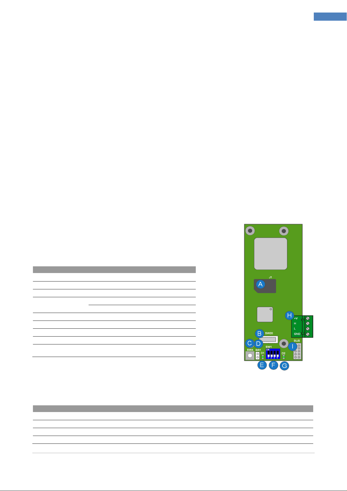
GSM / GPRS Module (Mod. SY860)
The module has two separate connectors to the bus allowing the
installation inside the box in the Control Panel or anywhere in the
plant by the CAN bus.
A Door SIM holder
B Tearproof tamper
C tamper
D Tamper Exclusion Closed Tamper: Tamper EXCLUDED
Open: tamper ENABLED
E STATUS LED
F Switch for the configuration ID (future use)
G STATUS LED
H Outside Bus for the connection of the module
I Interior Bus (Direct) to connect module when it is installed in the Control
LED D1 Description:
D1 is the GSM network:
Panel box
OFF Module not working
64ms On/ 800ms Off Module is not connected to the network
64ms On/ 3000ms Off Module properly connected to the network
64ms On/ 300ms Off GPRS connection is established
Installer Manual Microvideo srl www.microvideo.eu
Chapter 2 –Modules Description
Report
LED D2
Rif SY840
OFF No Faults
3 quick flashes at the boot
(100ms On /100ms Off x 3 times at the boot)
100ms On /300ms Off x 3 every 3 sec
100ms On /300ms Off x 2 every 3 sec CAN BUS communication error
End initialization module
SIM900-MCU communication error
Setting the Dip-Switch
We need the dip-switch for future use, so actually it must be configured as in the figure
below:
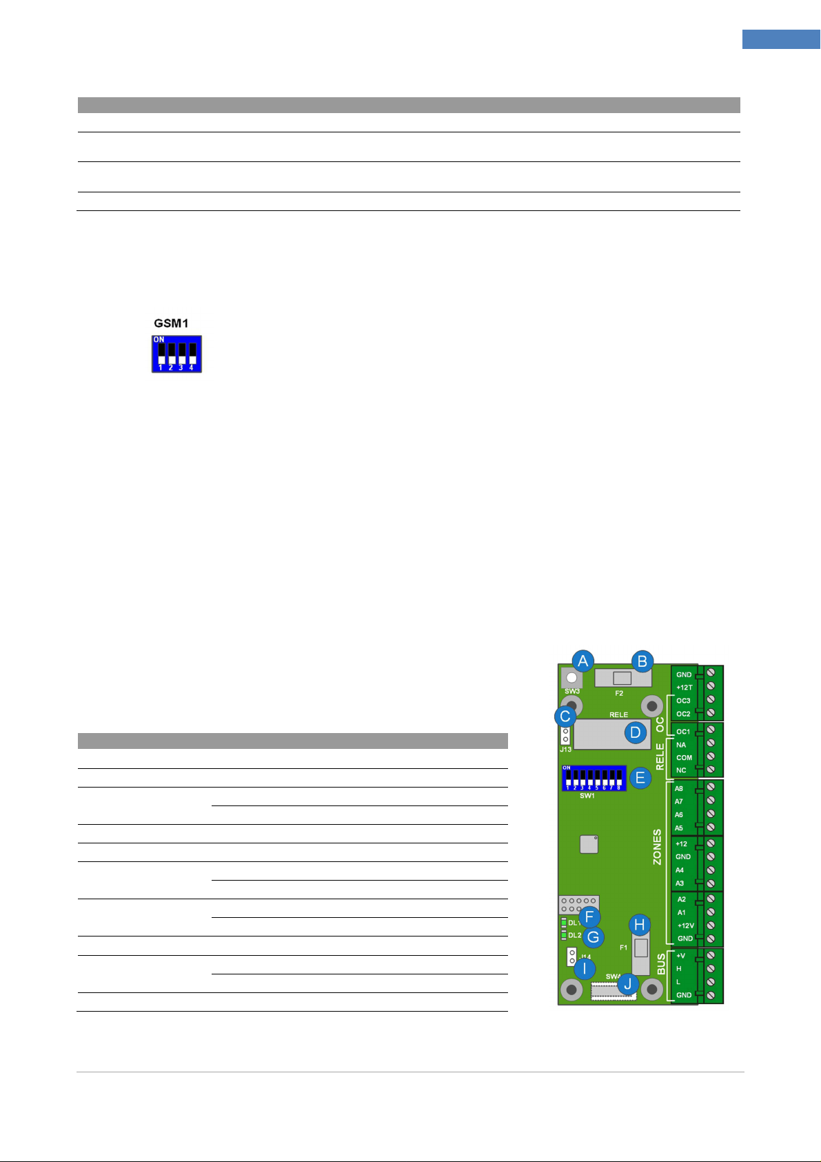
Expansion Module (Mod. SY840)
The expansion module allows to extend the number of inputs and outputs that the system
can handle.
The model SY840 has 8 inputs, 1 relay, and 3 open collectors. Equipped with tamper
protection that can be turned off as needed by easy tamper.
All inputs of the expansion can be configured as:
- NO, NO Balanced
- NC, NC WB, NC Double Bil Triple Bil
- Blinds
- InsImpImp
- InsImpLiv
All outputs:
- FIXED Output
- SIREN Output
- PULSE Output
12
A Tearproof Tamper
B F2: Fuse rapid (2A) to protect the net +12 T outputs
C Tamper Exclusion OFF: EXCLUDED tamper
ON: ENABLED tamper
D Relay: 3A - 24VDC
E Switch for ID configuration
F StatusLED Flashing: Corretto funzionamento
Off: anomalia
G Power LED On: module has power
Off : fault
H F1: rapid fuse (2A) to protect lines +12v of inputs
I Tearproof
Tamper Exclusion
J Tearproof Tamper
Off: excluded tamper
On: enabled tamper
Installer Manual Microvideo srl www.microvideo.eu
Chapter 2 –Modules Description
SY825
SY825
Expansion 1
Expansion
2
Expansion
3 Expansion
4 Expansion
5
Expansion
6
Expansion
7
Reader 1 Reader 2
Reader 3
Reader 4 Reader 5 Reader 6 Reader 7 Reader 8
Reader 1 Reader 2
Reader 3
Reader 4 Reader 5 Reader 6 Reader 7 Reader 8
It’s important to correctly configure the switch identifying the expansion module.
Depending on the number of expansions in the system, it is essential to configure the
switch as in the following figures
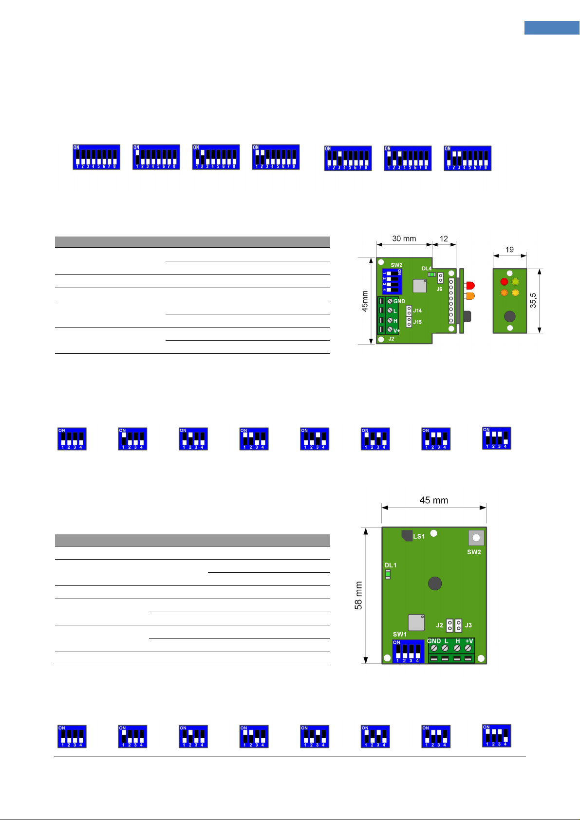
Inserter Jack Module (Mod. SY825)
13
J6 Tearproof Tamper
SW2 Dip-Switch per la configurazione dell'ID
J2 Bus System Connector (Can Bus)
J14-J15
DL4
End line Jumper
Status Led
Chiuso: tamper ESCLUSO
Aperto: tamper ABILITATO
Off: Inserted Jumper
On: NOT Inserted Jumper
Flashing: Correct function
Off: Fault
Configuration of dip switch for ID assignment
Wall Inserter Module (Mod. SY826)
LS1 Signal Buzzer
SW2 Tamper
Bus System Connector (Can Bus)
J2-J3 End line Jumper Off: Inserted Jumper
DL1
SW1 Dip Switch for ID Configuration
Status Led
On: NOT Inserted Jumper
Flashing: Correct function
Off: Fault
Pressed = Rest
Released = Alarm
Configuration of dip switch for ID assignment
Installer Manual Microvideo srl www.microvideo.eu

SY881
SY930
LAN Module (Mod. SY881)
Chapter 2 –Modules Description
14
SW2
J3-J4
JP1 Jumper By-Passing tearproof tamper
DL3 Future use
DL2 Led di stato Lampeggiante = corretto funzionamento
F2 Fusibile Protezione (uso futuro)
SW1 Tamper
JP2 Jumper By-Passing tamper
Tamper AntiStrappo
End line Jumper
Premuto = Riposo
Rilasciato = Allarme
Off: Inserted Jumper
On: NOT Inserted Jumper
Off = DISABLED Tamper
On = ENABLED Tamper
Pressed = Rest
Released = Alarm
Off = DISABLED Tamper
On = ENABLED Tamper
BUS Splitter (Mod. SY930)
J8 System BUS Connector (Can Bus)
JP1-JP2 CAN Bus End line Jumpers
SW2 Dip-switch for ID configuration
J7 System BUS Connector (Can Bus)
DL1 Status Led Flashing = correct function
DL2 Report Buzzer
Off: Inserted Jumper
On: NOT Inserted Jumper
Dip Switch Configuration for ID assignment
ID1 ID2 ID3 ID4
Installer Manual Microvideo srl www.microvideo.eu
WALL 4N
-8N
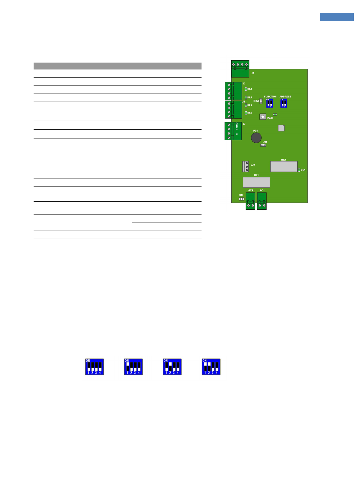
DVR WALL 4N-8N
J7 Bus connectionIRBox
J3 Channels 1 and 2 for camera supply
J4 Channels 3 and 4 for camera supply
J2 SYNERGY BUS connector
DL3
DL4
DL5
DL6
FUNCTION
ADDRESS Dip-switch for ID configuration
TEST
TACIT
J11 Jumper excluding Buzzer
PZ1 Buzzer reporting alarms
J20 Power supply jack for central unit synergy
DL1 Presence of electrical network
AC1 Power Connector
AC2 Power Connector
ON
DL2 Status Led flashing = correct function
Fuse status line 1
Fuse status line 2
Fuse status line 3
Fuse status line 4
SW-1: Future use
Function Switch
Puts the card in "test mode" mode in which the alarms do not generate
alarms on the alarm relay or buzzer
Temporary Silencing of the buzzer, canceled by closing and reopening
the door tamper
Jumper supplying DVR and
Cameras
ON → Disable recording and general
alarm, excluding the relay and the Buzzer
SW-2:
OFF → Enable recording and general
alarm, including the relay and buzzer
Close = Excluded Buzzer
Open = Active Buzzer
Closed = DVR and Cameras
powered
Open = DVR and Cameras not
powered
Chapter 2 –Modules Description
15
Dip Switch Configuration for ID assignment
ID1 ID2 ID3 ID4
Installer Manual Microvideo srl www.microvideo.eu
SY910
SY920
Radio Receiver Module (mod. SY910)
System BUS connector (Can Bus)
JP3-JP4 CAN Bus end line jumpers
SW5 Dip-switch for ID configuration
DL3 Status Led Flashing = correct function
DL1 Future use (Not used)
TAMP Jumper By-Passing tamper
LED1 Status Led flashing = correct function
Led Reception:
LED2
Flashes every time it receives a
communication from a remote control / radio
sensor
Chiuso = terminazioni inserite
Aperto = terminazioni NON inserite
Off = ENABLED Tamper
On = DISABLED Tamper
Chapter 2 –Modules Description
16
Dip Switch Configuration for ID assignment
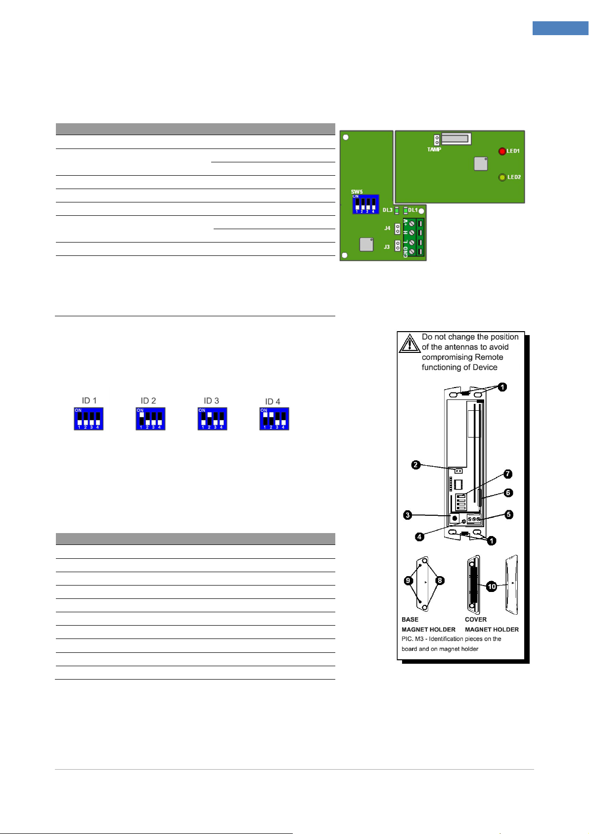
Radio Magnetic Contact Module (mod. SY920)
1 Holes for fixing screws
2 Connector Battery 3.6 V 2.4 Ah
3 tamper
4 Report LED: lights whenever the module sends a message
5 Terminal block for connecting auxiliary sensors
6 Reed Contact
7 Dip-Switches programming functions
8 Holes for base fixing screws
9 Pegs closing the magnet holder
10 Magnet Holder Lid with magnet
Installer Manual Microvideo srl www.microvideo.eu
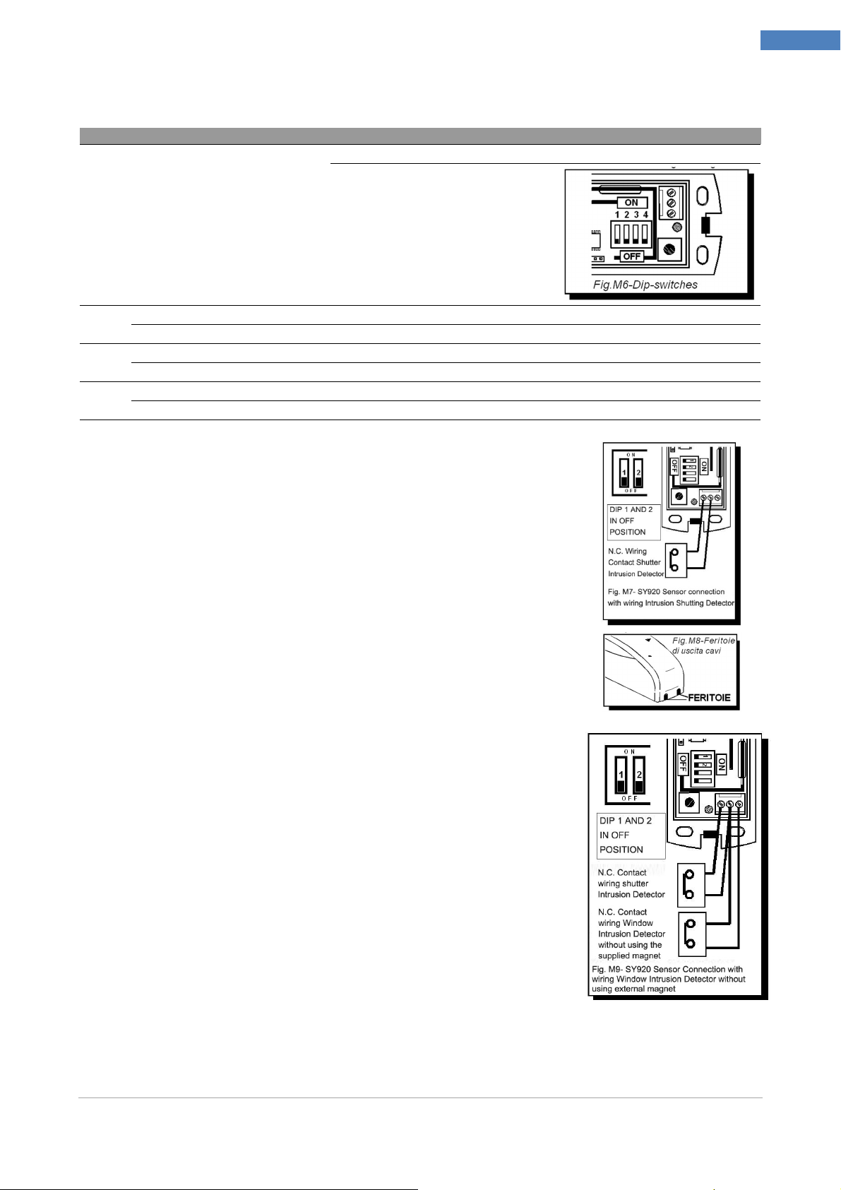
Dip-Switch
- SY920
Dip Switch Configuration
DIP n°1 Use only if dip number 2 is ON
Chapter 2 –Modules Description
OFF: medium sensibility of the pulse counter
ON: max sensibility of the pulse counter
17
DIP n°2
DIP n°3
DIP n°4
OFF: connection to the terminal block of a wire N.C.contact
ON: connection to the terminal block of a wire detector for for roller blinds (roller shutter protection). The sensor operates as pulse counter
OFF: supervision disabled
ON: supervision enabled
OFF: alert opening / closing disabled
ON: alert opening / closing enabled
MAGNET + NC Configuration
Connect the NC contact to the terminal block and make sure that
the dip switches # 1 and # 2 are in the OFF position.
WARNING! The device is only intended for connection to low
voltage safety. The connection to circuits with dangerous voltage
may cause danger.
For the cables, you can remove the preset forms provided on the lid
with a cutter, as shown in Figure M8.
N.B. You can connect multiple NC contacts in series with a single
sensor SY920. In this case, the control panel will not be able to
identify which of the NC contacts caused alarm.
NC + NC Configuration
You can connect an NC wired contact as an alternative to reed
contact provided on the device.
Connect the contact directly to the terminal block as shown in
Figure M9.
WARNING! In this case, DO NOT use the supplied external
magnet.
Installer Manual Microvideo srl www.microvideo.eu
Chapter 2 –Modules Description
SY921
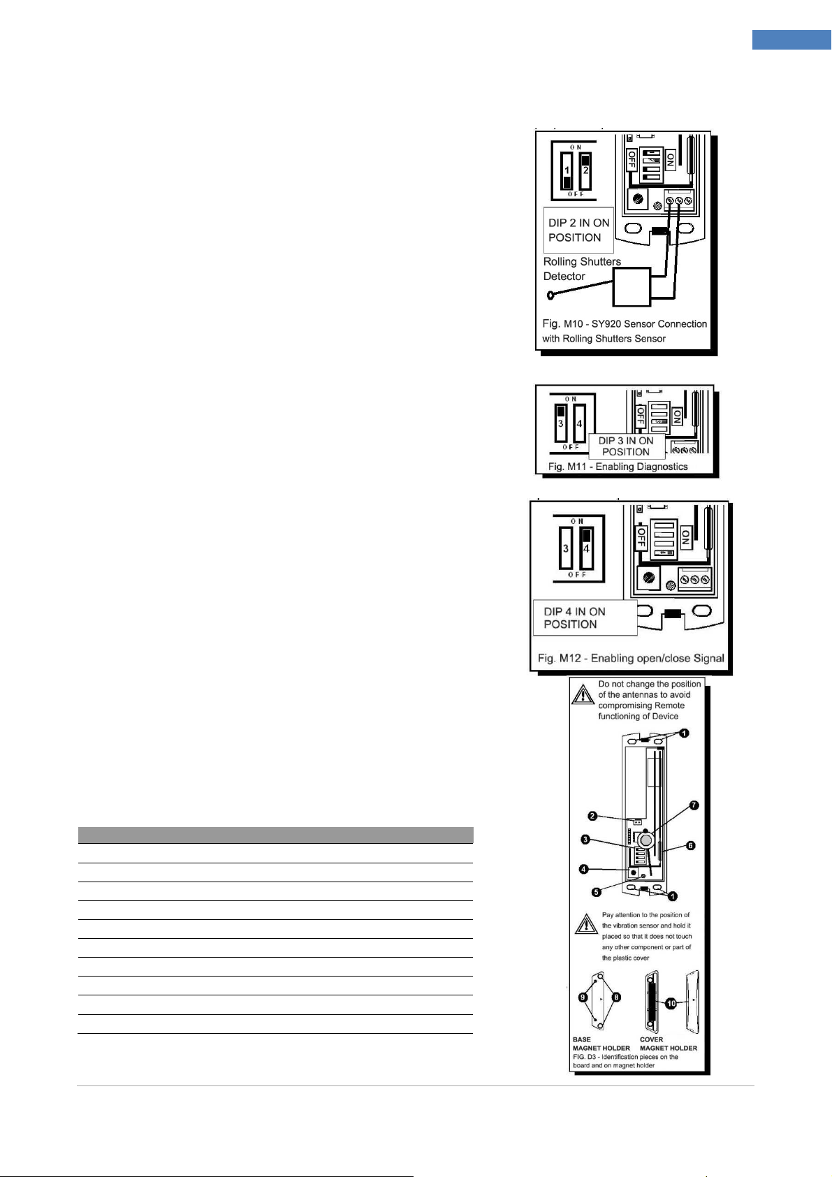
Configuration Magnet + Blinds
Connect the sensor to terminal block shutter and make
sure that dip switch # 2 is in the ON position to enable the
counter function.
WARNING! The device is only intended for connection to
low voltage safety. The connection to circuits with
dangerous voltage may cause danger.
N.B. Connect only one sensor shutter module SY920.
Diagnostics Function
If enabled by DIP switch No. 3, on the ON position, the
sensor transmits a signal every four hours of attendance at
Control Panel.
18
Report Open/Close Magnet/NC
If enabled by DIP switch No. 4, the sensor transmits to the
Control Panel each change of state of the Magnet:
example from the closed window to the open window and
conversely. Similarly for the wired NC contact connected
to the clamps, of course with the dip switch No. 2 in the
OFF position.
Inertial Radio Module (mod. SY921)
1 Holes for fixing screws
2 Connector Battery 3.6 V 2.4 Ah
3 Setup functions Dip-Switches
4 Tamper
5 Reporting Led
6 Reed Contact
7 Vibration Sensor
8 Holes for fixing screws of the base
9 Pegs closing the magnet holder
10 Magnet Holder Lid with magnet
Installer Manual Microvideo srl www.microvideo.eu
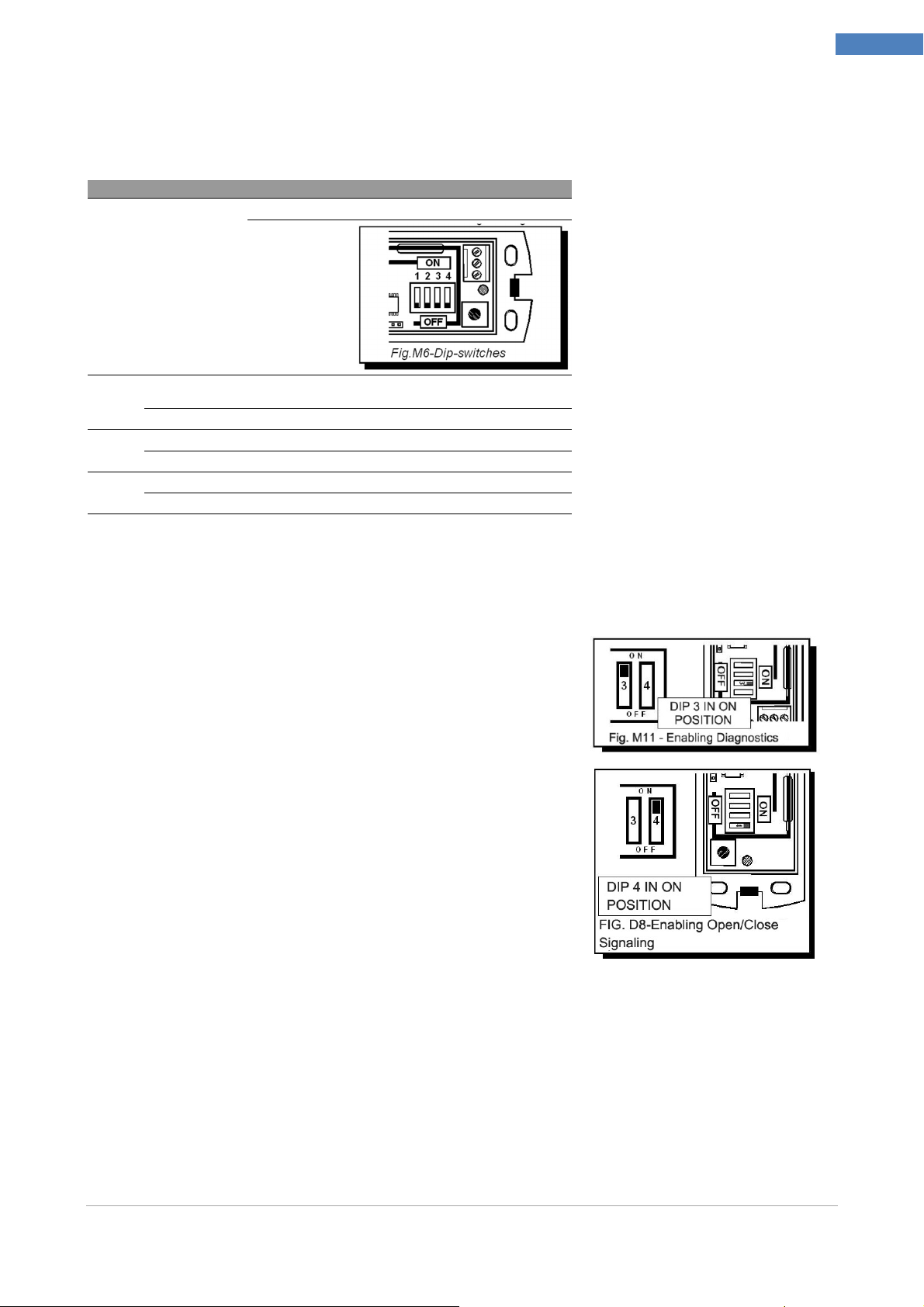
Dip-Switch
- SY921
Dip Switch Configuration
OFF: Average sensitivity of the vibration sensor
ON: max
sensitivity of the
vibration sensor
DIP n°1
DIP n°2
DIP n°3
DIP n°4
Use only if dip n.2
is in pos. ON
OFF: Vibration sensor disabled
ON: Vibration sensor activated
OFF: Supervision disabled
ON: Supervision enabled
OFF: Indication open / close disabled
ON: Indication open / close enabled
Chapter 2 –Modules Description
19
Supervision Function
If enabled by DIP switch No. 3, on the ON position, the
sensor transmits a signal every four hours of attendance at
Central.
Report Open / Close Magnet
If enabled by DIP switch No. 4, the sensor transmits to the central each change of state of
the Magnet: example from closed window to open window and so on.
Installer Manual Microvideo srl www.microvideo.eu
SY925
Dip-Switch
- SY921
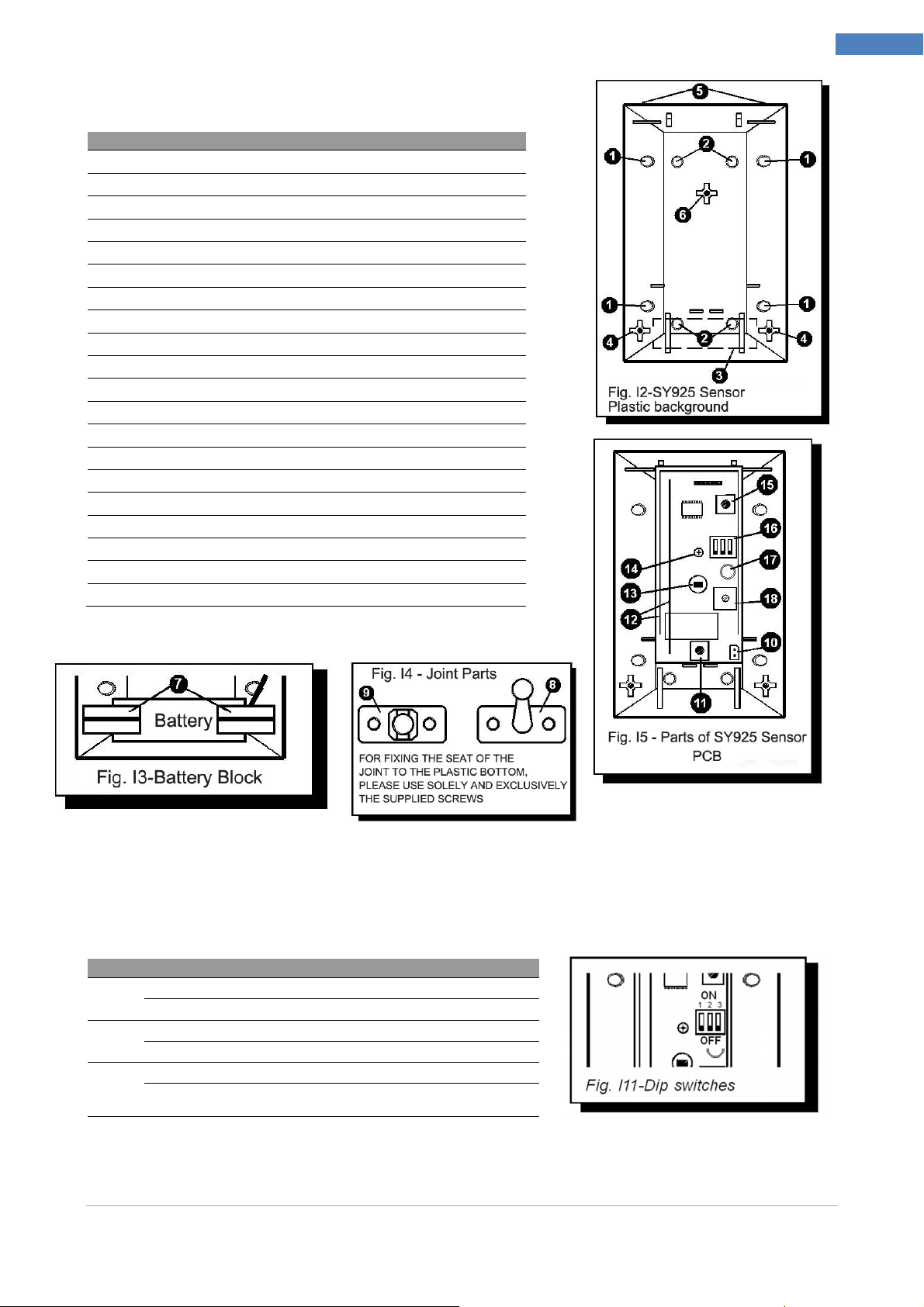
Motion Sensor Module (mod. SY925)
1 Arrangement for fastening holes on the wall so the angular
2 Arrangement for wall mounting holes
3 Battery Seat
4 Holes for insertion battery lockers
5 Holes for plastic cover fixing
6 Hole for circuits fixing screw
7 Plastic Stops battery locking (supplied)
8 Joint to fix on the wall
9 Swivel seat to be fixed to plastic background
10 3.6 V 2.4 Ah battery connector
11 Tamper with spring
12 Antennas
13 Pyroelectric Sensor
14 PCB Fixing Screws
15
16
17
18
19
20
Reset Button
Dip-Switches
Report Led
Sensitivity adjustment trimmer
Spring Seat tamper button
Plastic Cover Hooks
Chapter 2 –Modules Description
20
Dip Switch Configuration
DIP n°1
DIP n°2
DIP n°3
OFF: LED Warning Light off
ON: LED Warning Light on
OFF: Inhibition time between two readings always 5 sec.
ON: Inhibition time between detections 5 sec. For 1 hour, then 4 min.
OFF: Supervision disabled
ON: supervision enabled, the sensor transmits a presence signal every 4 hours
to control Panel
Installer Manual Microvideo srl www.microvideo.eu
Chapter 2 –Modules Description
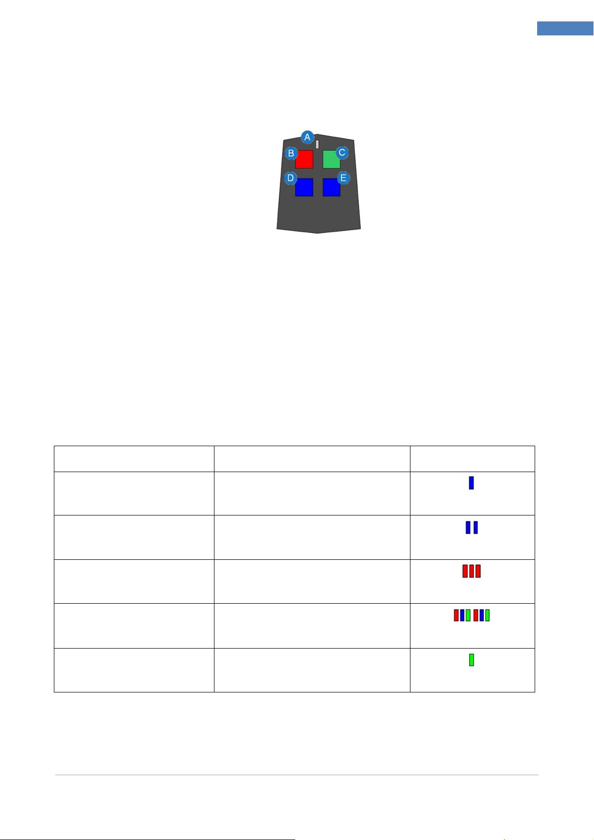
Radio Remote Control (mod. SY915)
The figure below shows a reproduction of the SY-915 Radio Remote Controls. Through the
Remote Control you can interact with the system and receive information on the status of
the loan with the LED. The Remote Control consists of 5 main parts:
A. Led Reporting
B. Red Button
C. Green Button
D. Blue Button 1
E. Blue Button 2
Interacting with Keys
Each key of remote control can be associated with 3 categories of actions:
Entries
Closings
21
Actions
To implement an action associated with a button you need to press the desired button and
wait until the LED flashes once RED light, this signal indicates that the remote control has
forwarded the request to perform the action to the Control Panel.
Once you press the button you have to wait for an answer from the Central always by the
flashing LED, the possible responses are:
Event Blink Sequence Example
Action Successfully
Performed
Action Executing failed 2 Blue
Arming System Completed
Successfully
Arming System Failed,
Zones in Alarm
1 Blue
3 Red
1 Green
1 Red - 1 Green - 1 Blue (3 times)
Disarming the Alarm System
Executed Successfully
N.B.
Each time you press a key (and the command is accepted by remote control through a
flashing red), you should always wait for the response from the plant, indicated by the
sequence of LEDs in the table above: if the answer is not displayed by the LED means
Installer Manual Microvideo srl www.microvideo.eu
1 Green
 Loading...