

MicroTurb MT-5810XTR2-8-44, MT-5810XTR2-9-48, MT-5810XTR2-10-54, MT-5810XTR2-12-52, MT-5810XTR2-13-54 Owner's Manual
...
OWNER’S MANUAL & INSTALLATION GUIDE
MicroTurb™ Ultimate Series Turbidity Filters w/ NextSand
highly effective and economical sediment / turbidity / particulate reduction filters with higher
flow rates, lower backwash rates, and finer filtration than the competition!
APPLICABLE MODELS: MT-5810XTR2 Series
PLEASE READ THIS MANUAL CAREFULLY BEFORE
ATTEMPTING INSTALLATION. FAILURE TO FOLLOW THESE
INSTRUCTIONS MAY AFFECT THE PERFORMANCE OF YOUR
SYSTEM, VOID YOUR WARRANTY, AND RESULT IN
PROPERTY DAMAGE.

2
Congratulations on the purchase of your MicroTurb™ Ultimate Series turbidity filtration
Hazards or unsafe practices that may result in personal injury
and/or severe property damage.
Hazards or unsafe practices that may cause operational
problems with your water treatment system.
system.
You have purchased one of the finest sediment/turbidity treatment systems on the market
today. All MicroTurb™ Ultimate Series water treatment systems utilize NextSand media, the
world's most advanced turbidity reduction media. In addition to providing much finer
filtration than traditional sand and multi-media filters, NextSand requires a lower backwash
rate and volume and has higher service flow rates for a given volume of media. This manual
is designed to provide owners, installers, and service technicians with detailed information
about the installation, start-up, and operation of your new filter system.
The brain of your MicroTurb™ system is the Fleck 5810XTR2 control valve. It is manufactured
by one of the world’s premier water treatment companies. The Fleck 5810 control valve is
well respected for its reliability, serviceability, simple operation, and value. The integrated
Fleck XTR2 touch screen valve controller offers unsurpassed simplicity of operation, yet
complete control over all important valve operations. The Fleck 5810 XTR2 Water Softener of
Filter Control Valve Service Manual is also included with your system. It includes additional
information regarding the operation of your valve, replacement parts lists, and more.
Your MicroTurb™ water treatment system is designed to offer low maintenance operation.
The control valve will perform regular backwash functions automatically. For your
convenience, your system has been pre-programmed for you at our factory. Should you
need to change any of the settings, simply follow the instructions provided in this manual.
IMPORTANT SAFETY SYMBOLS

3
Table of Contents:
GENERAL WARNINGS ……………………………………………………………………………………………...….. …….. 4
OPERATING CONDITIONS …………………………………………………………………………………………….…... 5
INSTALLATION ………………………………………………………………………………………………………….…..…..….. 6
Step 1 – Pre-Installation Inspection ……………………………………………………………..……… 7
Step 2 – Selecting an Installation Location ………………………………………………..…..... 7
Step 3 – Prepare Treatment Tank ………………………………………………………………..……… 9
Step 4 – Turn off the Water & Electric Water Heaters ………………………………….… 11
Step 5 – Prepare and Install Inlet and Outlet Plumbing Connection …….…… 12
Step 6 – Drain Line Installation …………………………………………………………………………..… 14
Step 7 – Control Valve Set-up ………………………………………………….……………………….….. 16
Step 8 – Initial Start-up and Leak Testing …………………………………………………......…. 19
BACKWASH ………………………………………………………………………………………………………………….…..……. 21
CHANGING TIME OF DAY ………………………………………………………………..…………………………..…… 22
CHANGING BASIC SETTINGS ……………………………………………………………………………………..…. 23
DIAGNOSTICS ………………………………………….…………………………………………………………………….…… 24
MASTER SETTINGS MODE …………………………………………………………………………………….……..… 26
OPERATION DURING A POWER FAILURE ………………………………………………………….…..…… 27
MAINTENANCE & TROUBLESHOOTING ……………………………………………………….…..….……. 28
WARRANTY INFORMATION ………………………………………………………………………………………..…… 29

4
GENERAL WARNINGS
Do not allow children or pets to play on or around the water filter.
Do not install or store this filter system where it will be exposed to freezing temperatures.
Do not tamper with controls.
Do not repair, replace, or attempt to service any part of the system unless specifically
instructed to in this manual and you have the understanding, tools, and skills necessary to
carry out the procedure.
Packing materials can be dangerous to children. Keep all packing material (plastic bags,
polystyrene, boxes, etc.) well out of children’s reach.
Individual components of this water treatment system, and the installed system, are heavy.
Precautions should be taken to prevent personal injury or strain. Do not move heavy
components without assistance if you are not physically capable of safely carrying out the
procedure.
If the water treatment system is to be left unattended for an extended period of time
(vacation, etc.), we strongly recommend that you turn off the water supply to the system, or
the whole house, while you are away.
If your water pipes are metal (galvanized or copper), they may be used to ground electrical
systems, appliances, or your phone line. If this is the case, be sure to install regulation
ground clamps to the metal pipe on each side of the control valve and connect a jumper
wire between the 2 clamps (#4 gauge solid copper wire recommended). Consult a certified
electrician or plumber if you are unsure.
5
OPERATING CONDITIONS
Minimum Water Pressure
20 PSI
Maximum Water Pressure
90 PSI*
Recommended Water Pressure
40-70 PSI
Water Temperature
36F to 100F (2 to 38C)
Minimum Air Temperature
32°F (0°C)**
pH Range
5.0*** to 9.0
The following chart provides guidance on the conditions required for successful operation of
your MicroTurb™ system.
USE OF THIS EQUIPMENT OUTSIDE OF THESE OPERATING CONDITIONS MAY
ADVERSELY AFFECT THE PERFORMANCE OF YOUR SYSTEM, RESULT IN SYSTEM
DAMAGE INCLUDING WATER LEAKS AND CORRESPONDING PROPERTY DAMAGE, AND
MAY VOID YOUR WARRANTY.
* While the MicroTurb™ system is built to withstand pressures exceeding 90 PSI, if your
water pressure is greater than 70 PSI, we recommend that you have a certified plumber
install a pressure reducing valve ahead of the MicroTurb™ system.
** The system cannot be subjected to freezing conditions or severe damage to the system
and your property could occur.
*** pH correction is strongly recommended where pH levels are less than 6.5 to prevent
damage to your control valve and plumbing system, and to prevent leaching of metals from
copper and brass plumbing components and solder in your home. Contact your dealer for
recommendations.
For fine filtration (3-5 microns), the optimal service flow rate should not be exceeded.
Satisfactory to good filtration can generally be achieved up to the recommended
maximum service flow rate as long as this level of flow rate is not sustained
continuously. See chart below.

6
MicroTurb™ Ultimate Series Flow Rates & Backwash Requirements:
Model
Optimal
Service Flow
Rate* (GPM)
Maximum
Service Flow
Rate* (GPM)
Backwash Flow Rate
at 40F Water Temp
(GPM)
Backwash Flow Rate
at 70F Water Temp
(GPM)
MT-5810XTR2-8-44
4.2
7.0
4.5
7
MT-5810XTR2-9-48
5.3
8.8
5.5
9
MT-5810XTR2-10-54
6.5
10.9 7 10
MT-5810XTR2-12-52
9.4
15.7
10
15
MT-5810XTR2-13-54
11.1
18.4
12
20
MT-5810XTR2-14-65
12.8
21.4
15
20
CONFIRM THAT YOUR WATER CONDITIONS, SERVICE FLOW RATE NEEDS, AND
AVAILABLE BACKWASH FLOW RATES MEET THE ABOVE SPECIFICATIONS FOR THE
MODEL YOU ARE INSTALLING BEFORE COMMENCING THE INSTALLATION PROCESS.
IF IN DOUBT, CALL YOUR DEALER FOR ADVICE. INSTALLED UNITS CANNOT BE
RETURNED.
INSTALLATION
WE RECOMMEND THAT YOU READ THIS ENTIRE MANUAL BEFORE STARTING THE
ACTUAL INSTALLATION. WHILE WE STRONGLY RECOMMEND THAT A LICENSED
PLUMBER PERFORM ALL INSTALLATION WORK, A MECHANICALLY-INCLINED
HOMEOWNER WITH SUITABLE PLUMBING KNOWLEDGE CAN INSTALL THIS SYSTEM.
IN ALL CASES, IT IS CRITICAL THAT THE INSTALLATION BE DONE IN ACCORDANCE
WITH THESE INSTRUCTIONS AND ALL APPLICABLE PLUMBING AND ELECTRICAL
CODES. BE SURE TO OBTAIN ALL REQUIRED PERMITS. IF THESE INSTRUCTIONS AND
THE APPLICABLE CODES ARE IN CONFLICT, THE RELEVANT PLUMBING/ELECTRICAL
CODE SHALL BE FOLLOWED. EQUIPMENT FAILURE, PERSONAL INJURY, OR PROPERTY
DAMAGE CAN RESULT IF THIS EQUIPMENT IS NOT INSTALLED PROPERLY.
7
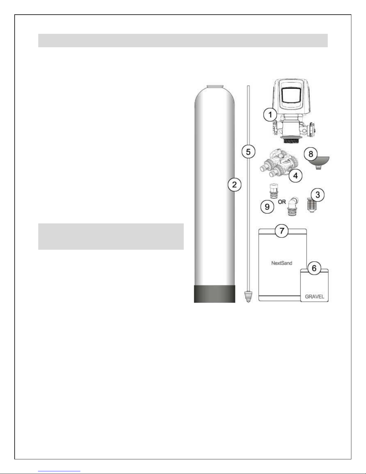
Step 1. – Pre-Installation Inspection
Inspect all of the components that you received with your unit. You should have received the
following:
1. Fleck 5810 XTR2 Control Valve
2. Media Tank
3. Upper Screen
4. Bypass Assembly w/ Bypass Valve and
1” NPT Connector Yokes (2)
5. Riser tube and lower distributor
6. Bag or box of gravel
7. Bag(s) or box(es) of NextSand media
8. Funnel
9. Drain Line Flow Control - DLFC
(attached to #1)
Step 2. – Selecting an Installation
Location
While exterior installation in warm climate
areas is possible, we strongly recommend
interior installation only. The system cannot
be allowed to freeze or severe system
damage could occur. The system should not
be exposed to rain and it should not be
installed in direct sunlight, as long-term exposure to UV light could damage components of
the system. Furthermore, direct sunlight could raise the internal water temperature in the
treatment tank and reduce backwash effectiveness.
In most cases, the system should be located AFTER your water pump and pressure tank(s)
and BEFORE all other water treatment equipment and your hot water heater.

8
IF YOU HAVE OTHER WATER TREATMENT EQUIPMENT, YOU SHOULD DISCUSS THE
ORDER OF YOUR TREATMENT EQUIPMENT WITH YOUR DEALER PRIOR TO
INSTALLATION.
Select a location for installation of your water filter that is within close proximity to the main
incoming water line of the home. The location should have a firm, level surface with enough
space for the unit itself and sufficient space surrounding the unit to facilitate maintenance.
WHILE WATER LEAKS ARE VERY RARE AND UNEXPECTED, YOUR WATER FILTER
SYSTEM SHOULD BE LOCATED NEXT TO A FLOOR DRAIN OR PROTECTED BY A WATER
LEAK DETECTION SYSTEM WITH AUTOMATIC SHUT-OFF VALVE TO PREVENT WATER
DAMAGE TO YOUR PROPERTY IN THE UNLIKELY EVENT OF A WATER LEAK.
RECOMMENDED WATER LEAK DETECTION SYSTEMS ARE AVAILABLE AT WWW.A-LEAK-
DETECTOR.COM.
You will also require a suitable drain to discharge waste water from the backwash cycle. A
drain standpipe for a washing machine, floor drain, or sump pump are excellent drain
options. We recommend that the drain line be connected to a minimum 1½" drain
standpipe or floor drain located ideally below the top of the head of your water filter. If
possible, the drain should be no farther than 20 feet from the system.
NOTE: NEVER CONNECT THE DRAIN LINE DIRECTLY INTO A DRAIN PIPE. ALLOW AN AIR
GAP BETWEEN THE DRAIN TUBING AND WASTE LINE TO PREVENT THE POSSIBILITY
OF BACK-SIPHONING. WE DO NOT RECOMMEND USE OF A CHECK VALVE AS IT MAY
BECOME CLOGGED WITH CONTAMINANTS EJECTED FROM THE SYSTEM DURING
BACKWASH.
You will also need access to a standard, non-switched, grounded 120 volt (60 Hz) electrical
outlet. An extension cord may be used to reach a suitable electrical outlet. If this option is
used, ensure that the extension cord is UL/CSA certified and of an appropriate wire gauge
for the application.

9
Step 3. – Prepare Treatment Tank
Two types of media are supplied with your MicroTurb™ system: gravel which forms the base
layer (underbedding) in your treatment tank, and a specialized sediment/turbidity reduction
media called NextSand.
Place the tank in the location where it will sit when the installation is complete. Note that the
black base of your tank is not permanently attached to the rest of the tank. If your tank
appears to be crooked, the base has likely been knocked out of alignment during shipping.
This can be correct by picking the tank up and tapping it on a hard surface while holding it
perpendicular to the floor. A few light taps will generally straighten it out.
Temporarily remove the distributor and riser tube assembly from the treatment tank. Hand
tighten the Fleck 5810XTR2 control valve on the tank and mark where the front of the tank
will be. Turn the tank so that the front of the tank is where you want it when it is full – once it
is full of media and water, it becomes very heavy and difficult to move!
Remove the control valve and re-insert the distributor and riser tube assembly into the tank.
The distributor, which looks like a cone-shaped plastic screen, is pre-connected to the end of
the long plastic riser tube which extends from the bottom of the tank to the top of the tank
where the control valve is attached. At the bottom of the tank, there is a recess in the center
of the tank to accept the distributor to keep it properly aligned. The riser tube has been pre-
cut to the correct height for you. When the distributor is correctly positioned, the top of the
riser tube will be approximately 1/8 to 1/4 of an inch below the top of the tank. If the tube is
flush or protruding above the top of the tank, the distributor tube is not nested correctly in the
recess at the bottom of the tank.
Add enough water to the tank to cover the lower distributor with a minimum of 6 inches of
water. This will prevent damage to the lower distributor as gravel is loaded. Place the funnel
into the tank so that the riser tube is in the middle. Place tape over the open end of the riser
tube. This will prevent gravel or media from accidentally going down the tube during the
following steps.
For the following steps, we recommend that you wear a dust mask. Take the bag/box of
gravel and, using a small scoop, add the gravel to the tank through the funnel to completely
cover the lower distributor. Use all of the gravel. Be sure to provide some downward
pressure on the riser tube while adding the gravel to ensure that the distributor does not shift
out of its recess or rise up. Ensure that you create an even layer of gravel across the bottom
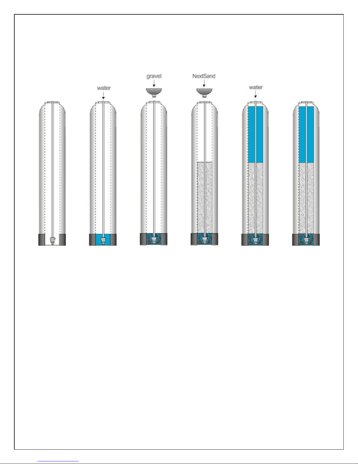
10
of the tank. A rigid piece of thin wall tubing (conduit, copper pipe, etc.), approximately 1”
longer than the tank height works well as a leveling tool if you need it. Ensure that the riser
tube remains centered in the opening at the top of the tank.
Once this is complete, add the NextSand media in the same manner. Use all of the media
provided. Depending on the capacity of the system, there will only be enough media to fill
the tank to about 1/2 to 3/4 full. This is normal. The media tank should never be filled to the
top of the tank as the remaining space, known as the “freeboard,” is necessary for the media
to have room to expand during the backwash cycle.
Once you have finished adding the media to the tank, remove the tape from the distributor
tube. Be careful not to pull upwards on the riser tube while doing this as it is important that
the distributor remain in its recess at the bottom of the tank.
Fill the media tank with water up to within a couple of inches of the top of the tank. This will
allow the media to pre-soak, thereby preventing media loss during the initial backwash.
 Loading...