

Page 1

4056 Meadowbrook Drive, Unit 126
London, ON Canada N6L 1E3
www.microtronix.com
MICROTRONIX
DX-4400
SD/HD/2K/4K-SDI TEXT & GRAPHICS
OVERLAY INSERTER
USER MANUAL – VERSION 1.5.1
DATE ISSUED: APRIL MARCH 15, 2019
Page 2

DX-4400
User Manual
Page 2 of 125
Document Revision History
This User Manual provides operating instructions and information the Microtronix DX-4400, SD/HD/2K/4K SDI
Text & Graphic Overlay Inserter, (Model Part Numbers: DX-4400-TI-2K and DX-4400-TI-4K).
The following table shows the document revision history.
Date
Rev.
Description
Mar. 30, 2017
0.9
Beta Release
Feb 14, 2017
1.0
Add 4K support
July 12, 2017
1.1
Add commands for output mode, chroma key for the PiP Text Inserter mode.
Added ancillary data enable/disable command for the PiP Text Inserter and Dual
Text Inserter modes.
Aug 2, 2017
1.2
Add user defined commands used to configure toggle and DIP switch actions.
Aug 23, 2017
1.2.1
Add information about licensing of 4K product.
Sep. 20, 2017
1.3
Add frame delay command for Dual & PiP modes.
Add double buffer option to allow running overlay with a single buffer. This will
improve performance for overlays with lots of updates.
Add ability to run QML scripts.
Nov. 2, 2017
1.3.1
Add QML application example for display of time, date and scrolling news feed.
Updated information on Serial/Network port user connections.
Fixed bug in QML scripts that required running in single buffer mode.
Added TZ command and changed TS command to change system time too.
Feb. 22, 2018
1.3.2
Re-formatted document layout with section numbering.
Fixed memory leak bug in QML.
April 11, 2018
1.3.3
Added Low Latency Dual mode and Dual mode with Zoom.
Aug. 10, 2018
1.4
Added feature to Savesets that allows the database to be used in memory thereby
reducing flash wear and allow Saveset replication.
Added Low Latency 4K mode.
Reduced command response to improve speed.
Nov. 6, 2018
1.4.1
Fix Compliance Appendix information and other minor edits
Jan. 8, 2019
1.4.2
Document Web UI feature and add Index
Feb. 20, 2019
1.5.0
Add Z4K and LPiP Modes. Update zoom description.
Mar. 4, 2019
1.5.1
Updated available fonts of Table 7
Page 3

DX-4400 – 3G-SDI Text & Graphics Overlay Inserter – User Manual
Page 3 of 125
How to Contact Microtronix
E-mail:
Sales Information: sales@microtronix.com
Technical Support: support@microtronix.com
Website:
General Website: http://www.microtronix.com
FTP Upload Site: http://microtronix.leapfile.com
Phone Numbers:
General: (01) 519-690-0091
Fax: (01) 519-690-0092
Product Design Customizations
Microtronix can customize the functionality of the DX-4400 – SD/HD/2K/4K-SDI Text & Graphics Overlay
Inserter software to customer requirements. Contact Microtronix sales (sales@microtronix.com) with your
requirements.
Safety Critical & Life System Applications – Notice to User
The Microtronix DX-4400 SDI Video product family is not designed or approved by Microtronix for use in safetycritical or life-critical system or application in which a failure or malfunction may result in one (or more) of the
following outcomes:
(a) death or serious injury to people,
(b) loss or severe damage to equipment/property, or
(c) environmental harm.
Microtronix assumes no liability for any consequential damages – whether direct or indirect – if the product is
used in this type of Application.
Page 4

DX-4400 – 3G-SDI Text & Graphics Overlay Inserter – User Manual
Page 4 of 125
Table of Contents
1 Key Product Features .............................................................................................................................. 10
1.1 Supported Functionality ................................................................................................................... 10
1.2 Product Variants ............................................................................................................................... 11
1.3 Package Contents ............................................................................................................................ 11
2 Introduction .............................................................................................................................................. 12
2.1 Text and Graphics Overlay OSD Features ...................................................................................... 12
2.2 Other Features ................................................................................................................................. 12
2.3 User Connections ............................................................................................................................. 13
2.3.1 RS-232 Control Port .................................................................................................................. 13
2.3.2 USB Serial Port ......................................................................................................................... 13
2.3.3 Ethernet Port ............................................................................................................................. 13
2.4 Hardware .......................................................................................................................................... 13
2.4.1 Enclosure Dimensions .............................................................................................................. 14
2.5 Power Requirements ........................................................................................................................ 14
2.5.1 DC Power Connector ................................................................................................................ 15
2.6 Environmental Operating Limits ....................................................................................................... 15
3 Operation ................................................................................................................................................. 16
3.1 Powering on the DX-4400 ................................................................................................................ 16
3.2 Modes of Operation .......................................................................................................................... 16
3.3 Default Configuration and Video Mode ............................................................................................ 17
3.4 OSD Layers ...................................................................................................................................... 17
3.5 LED Status Indicators ...................................................................................................................... 18
3.6 External Control of the DX-4400 ...................................................................................................... 18
3.6.1 Serial Control Mode of Operation ............................................................................................. 19
3.6.1.1 USB 2.0 to RS-232 Serial Port Adapter Kit ....................................................................... 19
3.6.1.2 USB Serial Port .................................................................................................................. 19
3.6.2 Network Control Using Raw TC/IP ........................................................................................... 19
3.6.3 Network Control Using Web UI ................................................................................................. 20
3.6.3.1 Connecting to the Web UI ................................................................................................. 20
3.6.3.2 Default Static Network IP Address .................................................................................... 21
3.6.3.3 DHCP Assignment of Network IP Address ........................................................................ 21
3.6.4 Serial/Network Control – Command Port Syntax ..................................................................... 22
3.6.5 Manual Mode of Operation ....................................................................................................... 23
3.6.5.1 Toggle Switch Settings ...................................................................................................... 23
3.6.5.2 DIP Switch Settings ........................................................................................................... 23
3.7 Setting DX-4400 Mode of Operation ................................................................................................ 23
3.7.1 Set Mode Commands ............................................................................................................... 25
3.7.1.1 Example - Set Mode Command ........................................................................................ 26
3.8 Overview of Overlay Fields .............................................................................................................. 26
3.8.1 Coordinate System and Field Position ...................................................................................... 27
3.8.2 Color and Transparency ........................................................................................................... 28
3.8.3 Text Overlay Fields ................................................................................................................... 28
3.8.3.1 Available Text and Symbols Available Font & Symbol ...................................................... 28
3.8.3.2 Text Overlay Command Syntax ......................................................................................... 29
3.8.3.3 Example: Text Drawing Style Options ............................................................................... 30
3.8.3.4 Example: Sample of DX-4400 Font Styles ........................................................................ 31
3.8.4 Graphic Overlay Fields ............................................................................................................. 32
3.8.4.1 Rectangle Shapes ............................................................................................................. 32
3.8.4.2 Example of Drawing an Ellipse. ......................................................................................... 33
3.8.4.3 Circle and Ellipse Shapes .................................................................................................. 33
3.8.4.3.1 Example of Drawing an Ellipse. ..................................................................................... 33
3.8.4.4 Line Shape ......................................................................................................................... 33
3.8.4.4.1 Example of Drawing a Line ............................................................................................ 33
Page 5

DX-4400 – 3G-SDI Text & Graphics Overlay Inserter – User Manual
Page 5 of 125
3.8.4.5 Graphic Overlay Command Syntax ................................................................................... 33
3.8.5 Image Overlay Fields ................................................................................................................ 35
3.8.5.1 Image Field File Formats ................................................................................................... 35
3.8.5.2 Image Overlay Command Syntax ...................................................................................... 35
3.8.5.3 Example: Image Field Overlay Display.............................................................................. 37
3.8.6 QML Field Commands .............................................................................................................. 37
3.8.6.1 QML Image Overlay Command Syntax ............................................................................. 38
3.8.6.2 Example: QML Field Example of Time, Date & Scrolling News Feed Overlay ................. 38
3.9 Video Path Settings & Control.......................................................................................................... 40
3.9.1 PiP Size and Position Commands ............................................................................................ 40
3.9.1.1 Example: Configuring Side By Side Display Using PiP Commands ................................. 42
3.9.1.2 Example: Switching between two inputs using a Full Screen PiP ..................................... 42
3.9.2 Video Zoom Commands ........................................................................................................... 43
3.9.2.1 Example: Configuring a Split Screen Display Using PiP and Zoom Commands .............. 44
3.9.3 Video Output Mode Commands ............................................................................................... 45
3.9.3.1 Conversion of Video Formats ............................................................................................ 46
3.9.4 Video Background Color Command ......................................................................................... 46
3.9.5 Video Alpha Commands ........................................................................................................... 47
3.9.5.1 Example: Alpha-blending of Computer-generated Graphics Overlay ............................... 48
3.9.6 Video Buffering and Frame Delay ............................................................................................. 49
3.9.6.1 Video Frame Delay Compensation Commands ................................................................ 49
3.9.6.1.1 Example: Setting Frame Delay of SDI Output ............................................................... 50
3.9.7 Miscellaneous Video Path, Status & Report Control Port Commands ..................................... 51
3.10 Time Commands .............................................................................................................................. 51
3.11 Database Saveset Commands ........................................................................................................ 52
3.11.1 Saveset Default Commands ..................................................................................................... 52
3.12 User Defined Commands ................................................................................................................. 53
3.12.1 Configuring Toggle Switch Functions ....................................................................................... 53
3.12.1.1 Example 1: Toggle Switch Control of PiP Window Functions ........................................... 54
3.12.1.2 Example 2: Toggle Switch Control of ARM Graphics Overlay Fields ................................ 54
3.12.1.3 Example 3: Controlling the Display of a Single Text Field................................................. 55
3.12.2 Configuring DIP Switch Functions ............................................................................................ 55
3.12.2.1 Example: Control of PiP Window Size via DIP Switch Settings ........................................ 56
3.13 Miscellaneous Control Port – System Status & Report Commands ................................................ 57
3.13.1 Serial Port Command Buffer Reset .......................................................................................... 57
3.14 ARM SoC Processor ........................................................................................................................ 57
3.15 Network Interface ............................................................................................................................. 57
3.16 Linux OS Root Account Login .......................................................................................................... 57
3.16.1 Default Linux OS User Login .................................................................................................... 58
3.16.2 Mounting Removable File Systems .......................................................................................... 58
3.16.3 Copying Files ............................................................................................................................ 58
3.16.4 Adding New Font Files .............................................................................................................. 58
3.16.5 Date and Time Configuration .................................................................................................... 59
3.16.5.1 Time Zone .......................................................................................................................... 59
3.16.5.2 Linux OS System Time ...................................................................................................... 59
3.16.5.3 Accessing NTP Servers ..................................................................................................... 59
4 IP Core Firmware .................................................................................................................................... 60
4.1 IP Core Firmware Files .................................................................................................................... 60
4.1.1 IP Core Firmware Upgrades ..................................................................................................... 60
4.2 Firmware Licensing of 4K Features ................................................................................................. 61
4.2.1 IP Core License Installation ...................................................................................................... 61
5 Using the Web UI .................................................................................................................................... 62
5.1 Connecting to the Web UI ................................................................................................................ 62
5.2 Overview of Web UI ......................................................................................................................... 63
5.2.1 Web UI Menu ............................................................................................................................ 63
5.3 Web UI – General Environment Menu ............................................................................................. 63
5.3.1 General Environment – Mode of Operation Page .................................................................... 63
Page 6

DX-4400 – 3G-SDI Text & Graphics Overlay Inserter – User Manual
Page 6 of 125
5.3.2 General Environment – Manage Savesets Page ..................................................................... 64
5.3.2.1 Use of Savesets ................................................................................................................. 65
5.3.3 General Environment – Control Interface Page ........................................................................ 66
5.3.4 General Environment – Status Page ........................................................................................ 66
5.4 Web UI – Video Setup Menu ............................................................................................................ 67
5.4.1 Video Setup – Alpha Blend Page ............................................................................................. 67
5.4.2 Video Setup – Background Color Page .................................................................................... 68
5.4.3 Video Setup – Frame Delay Compensation Page .................................................................... 69
5.4.3.1 Video Setup – PiP Display Settings Page ......................................................................... 69
5.4.3.2 Video Setup – Video Control Page .................................................................................... 70
5.4.3.3 Video Setup – Video Output Page ..................................................................................... 71
5.4.3.4 Video Setup – Zoom Page ................................................................................................ 71
5.4.4 Web UI – Overlay Fields Menu ................................................................................................. 72
5.4.4.1 Overlay Fields – Graphic Field Page ................................................................................. 72
5.4.4.1.1 Use of Graphic Fields Page ........................................................................................... 72
5.4.4.2 Overlay Fields – Image Field Page ................................................................................... 72
5.4.4.2.1 Use of Image Field Page................................................................................................ 73
5.4.4.3 Overlay Fields – QML Script File Page ............................................................................. 73
5.4.4.3.1 Management of QML Script Files .................................................................................. 74
5.4.4.4 Overlay Fields – Text Fields Page ..................................................................................... 75
5.4.4.4.1 Use of Text Fields Page ................................................................................................. 75
5.5 Web UI – User-defined Commands Menu ....................................................................................... 76
5.5.1 User-defined Commands – Reset Page ................................................................................... 76
5.5.2 User-defined Commands – DIP Switches ................................................................................ 76
5.5.2.1 Use of DIP Switch Page .................................................................................................... 77
5.5.3 User-defined Commands – Toggle Switch Left Page ............................................................... 77
5.5.3.1 Use of Toggle Switch Left Page ........................................................................................ 78
5.5.4 User-defined Commands – Toggle Switch Right Page ............................................................ 78
5.5.4.1 Use of Toggle Switch Right Page ...................................................................................... 79
5.6 Web UI – File Manager Menu .......................................................................................................... 79
5.6.1 File Manager – DX Command Files Page ................................................................................ 79
5.6.1.1 Use of Command Files Manager Page ............................................................................. 80
5.6.2 File Manager – Font Files Page ................................................................................................ 81
5.6.2.1 Use of Image Files Manager Page .................................................................................... 81
5.6.3 File Manager – Image Files Page ............................................................................................. 81
5.6.3.1 Use of Font Files Manager Page ....................................................................................... 81
5.6.4 File Manager – QML Files Page ............................................................................................... 82
5.7 Web UI – System Configuration Menu ............................................................................................. 83
5.7.1 System Configuration – Authentication Page ........................................................................... 83
5.7.2 System Configuration – Date and Time Page .......................................................................... 83
5.7.3 System Configuration – Maintenance Page ............................................................................. 84
5.7.4 System Configuration – System Log Page ............................................................................... 85
5.7.5 System Configuration – Web Server Page ............................................................................... 86
5.7.6 System Configuration – Edit System Files Page ...................................................................... 86
5.8 Web UI – System Status Menu ........................................................................................................ 87
5.8.1 System Status – Command Line Page ..................................................................................... 87
5.8.2 System Status – System Logs Page ........................................................................................ 87
6 Extended Font Tables ............................................................................................................................. 89
6.1 Wingding Font .................................................................................................................................. 89
6.2 Extended ASCII Fonts ...................................................................................................................... 92
7 Troubleshooting ....................................................................................................................................... 93
8 Product Warranty..................................................................................................................................... 94
8.1 Hardware Warranty .......................................................................................................................... 94
8.2 Firmware Warranty ........................................................................................................................... 94
8.2.1 Limited Liability ......................................................................................................................... 94
Appendix A: Description of the DX-4400 OEM Board ............................................................................... 95
A.1 DX-4400 OEM Board – Hardware Features .................................................................................... 95
Page 7

DX-4400 – 3G-SDI Text & Graphics Overlay Inserter – User Manual
Page 7 of 125
A.1.1 SDI Video Interfaces ................................................................................................................. 96
A.1.2 DB9 RS-232 Control Port, J10 .................................................................................................. 96
A.1.3 USB Serial Control Port, J11 .................................................................................................... 96
A.1.4 USB OTG Port, J4 .................................................................................................................... 96
A.1.5 RS-232 Serial Console Port, J5 ................................................................................................ 96
A.1.6 10/100/1G Ethernet Port, J2 ..................................................................................................... 97
A.1.7 Power Requirements ................................................................................................................ 97
A.1.8 12VDC Board Power Header, J7 & J8 ...................................................................................... 97
A.1.9 Fan Header, J9 ......................................................................................................................... 97
Appendix B: Establishing User Connections to the DX-4400 Product ...................................................... 99
B.1 Installation of USB to RS-232 Serial Port Adapter Software ........................................................... 99
B.1.1 ICUSB232V2 Software Drivers ................................................................................................. 99
B.1.1.1 Installation of ICUSB232V2 Serial Driver and Terminal Emulator Program ...................... 99
B.2 Establishing RS-232 Serial Communication to a PC ..................................................................... 100
B.3 Establishing TCP/IP Connection to the DX-4400 Product ............................................................. 102
B.4 Establishing SSH Connection to the DX-4400 Product ................................................................. 104
Appendix C: How to Image a New SD Card ............................................................................................ 106
C.1 From a Windows Machine .............................................................................................................. 106
C.2 From a Linux Machine .................................................................................................................... 106
Appendix D: Time Zone Names ............................................................................................................... 107
Appendix E: Regulatory Compliance Information .................................................................................... 112
E.1 Industry Canada (IC) ...................................................................................................................... 112
E.2 Federal Communications Commission (FCC) Declaration of Conformity...................................... 114
E.3 CE Declaration of Conformity ......................................................................................................... 116
E.4 RoHS/REACH Compliance Statement .......................................................................................... 119
Index ............................................................................................................................................................. 121
Page 8

DX-4400 – 3G-SDI Text & Graphics Overlay Inserter – User Manual
Page 8 of 125
Listing of Tables
Table 1: Description of SDI LED Status Indicators 18
Table 2: Command Port Acknowledgement Codes 22
Table 3: Operation of 2-Position Momentary Toggle Switch 23
Table 4: Operation of 4-Postion DIP Switch 23
Table 5: DX-4400 Modes of Operation 24
Table 6: Set Mode Command Syntax 26
Table 7: Text Font and Symbol Font Attributes 29
Table 8: Text Overlay Command Syntax 29
Table 9: Graphic Overlay Command Syntax 34
Table 10: Supported Image Formats 35
Table 11: Image Field Overlay Command Syntax 36
Table 12: QML Field – Image Overlay Command Syntax 38
Table 13: List of Supplied Example QML Files 39
Table 14: PiP Size & Position Command Syntax 41
Table 15: Zoom Command Syntax 43
Table 16: Video Output Mode Command Syntax 45
Table 17: Video Background Color Command Syntax 47
Table 18: Video Alpha Command Syntax 47
Table 19: Video Frame Delay Compensation Command Syntax 50
Table 20: Miscellaneous Video Path, Status & Report Control Port Commands 51
Table 21: Time Command Syntax 51
Table 22: Database Saveset Command Syntax 52
Table 23: Command Syntax for Saveset Default Values 52
Table 24: Toggle Switch – User Defined Command Syntax 53
Table 25: DIP Switch User Defined Command Syntax 55
Table 26: DIP Switch – User Defined Group Command Syntax 56
Table 27: Miscellaneous Control Port Commands 57
Table 28: Windings Character Table 89
Table 29: Windings 2 Character Table 90
Table 30: Windings 3 Character Table 91
Table 31: Extended ASCII Character Table 92
Table 32: Troubleshooting Symptoms 93
Table 33: RS-232 Serial Control Port, DB9 Pin Assignments 96
Table 34: RS-232 Serial Console Port, J5 97
Table 35: 12VDC 2-Pin Header, J8 97
Table 36: Fan 3-Pin Header, J9 98
Table 37: Microtronix RoHS/REACH Compliant DX-4400 SDI Video Products 119
Table 38: List of SCHC Compounds 119
Page 9

DX-4400 – 3G-SDI Text & Graphics Overlay Inserter – User Manual
Page 9 of 125
Listing of Figures
Figure 1: DX-4400 – SD/HD/2K/4K-SDI Text & Graphics Overlay Inserter Product 14
Figure 2: 12Vdc 2.5A 100-240VAC Power Adapter 14
Figure 3: DX-4400 Layer Order 17
Figure 4: DC Power LED 18
Figure 5: SDI Input / Output Status LEDs 18
Figure 6: DX-4400 Web UI Home Page 21
Figure 7: Examples of the DX-4400 Text Drawing Styles 31
Figure 8: Examples of the DX-4400 Font Styles 32
Figure 9: Image Field Overlay Display 37
Figure 10: QML Field Example of Time, Date, & Scrolling News Feed Overlay 39
Figure 11: Side by Side Display Example 42
Figure 12: Split Screen Display Example 45
Figure 13: Example of Computer-generated Graphics Overlay with Transparency 49
Figure 14: DX-4400 Web UI Home Page 62
Figure 15: General Environment – Mode of Operation Page 64
Figure 16: General Environment – Manage Database and Saveset Page 65
Figure 17: General Environment – Control Interface Page 66
Figure 18: General Environment – Command Files Page 67
Figure 19: Video Setup – Alpha Blend Page 68
Figure 20: Video Setup – Alpha Blend Page 68
Figure 21: Video Setup – Frame Delay Compensation Page 69
Figure 22: Video Setup – PiP Display Settings Page 70
Figure 23: Video Setup – Video Control Page 70
Figure 24: Video Setup – Video Output Mode Page 71
Figure 25: Video Setup – Video Output Mode Page 71
Figure 26: Overlay Fields – Graphic Field Page 72
Figure 27: Overlay Fields – Image Field Page 73
Figure 28: Overlay Fields – Image Field Page 74
Figure 29: Overlay Fields – Image Text Page 75
Figure 30: User Defined Command – Reset Page 76
Figure 31: User Defined Command – DIP Switch Page 77
Figure 32: User Defined Command – Toggle Switch Left Page 78
Figure 33: User Defined Command – Toggle Switch Right Page 79
Figure 34: File Manager – Command Files Page 80
Figure 35: File Manager – Font Files Page 82
Figure 36: Overlay Configuration – QML Files Page 82
Figure 37: System Configuration – Authentication Page 83
Figure 38: System Configuration – Time and Date Page 84
Figure 39: System Configuration – Maintenance Page 85
Figure 40: System Configuration – System Log Page 85
Figure 41:System Configuration – Web Server Page 86
Figure 42:System Configuration – Web Server Page 86
Figure 43: System Status – Command Line Page 87
Figure 44: System Status – System Log Page 88
Figure 45: DX-4400 – SD/HD/2K/4K-SDI Text & Graphics Overlay Inserter OEM Board 95
Figure 46: USB to DB9 RS-232 Serial Port Adapter Kit 99
Figure 47: PuTTY Serial Port Session Settings 101
Figure 48: PuTTY Serial Port Terminal Settings 101
Figure 49: PuTTY Serial Port Settings 102
Figure 50: PuTTY TCP/IP Session Settings 103
Figure 51: PuTTY Terminal Settings 103
Figure 52: PuTTY SSH Session Settings 105
Figure 53: PuTTY SSH Terminal Settings 105
Page 10

DX-4400 – 3G-SDI Text & Graphics Overlay Inserter – User Manual
Page 10 of 125
1 Key Product Features
The key hardware features of the DX-4400 – SD/HD/2K/4K-SDI Text & Graphics Inserter includes:
• Two 75Ω 3G-SDI input ports
• Four 75Ω 3G-SDI output ports
o Two for overlay on output
o Loop outputs for SDI input 1 and input 2
• One DB9 RS-232 Serial Control Port
• One USB Serial Control Port
• One USB OTG Port,
• One 10/100/1000 Ethernet Port, and
• Integrated real-time clock with support for NTP & PTP protocols.
1.1 Supported Functionality
The DX-4400 SD/HD/2K/4K-SDI Text & Graphics Overlay Inserter supports the following functionality:
• Video Input formats::
o NTSC @ 29.97 fps (frames per second)
o PAL @ 25 fps
o 720p @ 25 / 29.97 / 30 / 50 / 59.94 / 60 fps
o 1080i @ 23.98 / 24 / 25 / 29.97 / 30 fps
o 1080p @ 23.98 / 24 / 25 / 29.97 / 30 / 50 / 59.94 / 60 fps
o 1080psf @ 23.98 / 24 / 25 / 29.97 / 30 fps
o 2048x1080p @ 23.98 / 24 / 25 / 29.97 / 30 / 50 fps
o UHD 4K: 3840x2160p @ 23.98 / 24 / 25 / 29.97 / 30 fps (Dual Link, 3 Gb/s SDI, Quad and 2SI
mapping)
o DCI 4K: 4096x2160p @ 23.98 / 24 / 25 / 29.97 / 30 fps (Dual Link, 3 GB/s SDI, Quad and 2SI
mapping)
o YCbCr 4:2:2
Note: Support for 4K video is an optional firmware upgrade.
• Video Output automatically adjusts to match the input video format
• Text and Graphics Overlay OSD:
o Multiple overlay layers
o Unrestricted independent text or graphic Fields per layer
o Fields support text, rectangle, line, circle, ellipse, and graphic images.
o Filled or open shapes
o Size, color, transparency and position control
o Configurable background color for text
o Alpha blended text and background
o Alpha blending of graphic components
o Scaling of text and graphic images
o Text scrolling and crawling for news-feed applications
• User configurable frame delay from 1-20 frames
• Digital zoom (video scaling) of PiP input
• Supports the Qt Meta Language (QML) for enhancing user interface-centric applications
• File storage of user configuration and text fields for auto system recovery after power-off
Page 11

DX-4400 – 3G-SDI Text & Graphics Overlay Inserter – User Manual
Page 11 of 125
• User control via: RS232 Control port, USB Serial Control port, a raw TCP/IP connection using either; a
Telnet (terminal emulator) Client, a SSH connection or through a Web UI browser interface.
1.2 Product Variants
The DX-4400 product has two variants:
1) PN: DX-4400-TI-2K – the SD/HD/2K Dual Channel -SDI Text & Graphics Inserter, which supports 2
independent SDI links at standard broadcast video resolutions including SD, HD, FHD and 2K.
2) PN: DX-4400-TI-4K – the SD/HD/2K/4K-SDI Text & Graphics Inserter supports all the features of the
above product with additional support for 4K video resolutions in a dual-link 3G-SDI configuration.
1.3 Package Contents
The DX-4400 package contents include either the DX-4400-TI-2K or the DX-4400-TI-4K hardware product and
the following items:
• PN: 811-USB-RS-232 – the USB to DB9 RS-232 Serial Port MM Adapter Kit,
• PN: 811- USB2HABM6 – a 6ft Mini USB 2.0 Type A to Mini B Cable Adapter,
• PN: 811-USB-OTG – a 5" OTG Micro USB to USB Male-to-Female Cable Adapter,
• PN: 2880SDC8 – 8GB microSDHC Class 4 Flash Card, (installed in microSD Card slot)
• PN: 5883-PSC30U-120L6 – a 100-240VAC – 12VDC / 2.5A power adapter, and
• User Manual & software utilities on CD.
Page 12

DX-4400 – 3G-SDI Text & Graphics Overlay Inserter – User Manual
Page 12 of 125
2 Introduction
The Microtronix SD/HD/2K/4K-SDI Text & Graphics Overlay Inserter (PN: DX-4400-xx) is a high performance
single/dual input Video Text Inserter supporting alpha blended text overlay / on screen display (OSD) on
progressive, PsF and interlaced SD, HD, FHD, 2K and 4K video formats. It is designed for use in broadcast,
professional video recording studios and embedded video information applications requiring live insertion of
graphics and text streams onto a SDI video signal. Low-latency configurations enable the unit to operate with
less then one frame of video delay between the input and the output.
2.1 Text and Graphics Overlay OSD Features
Features of the overlay on screen display (OSD) include:
• ARM Linux graphics processor,
• User selectable database Savesets to store field information,
• Fields support Text, Rectangles, Lines, Circles, Ellipse and Image modes,
• Text scrolling and crawling for news feed applications,
• Text Field of up to 512 characters,
• Alpha blending of the text for smooth edges,
• Independent color selection of fields,
• Configurable background color of text fields,
• Transparency control,
• Independent ON/OFF control of fields,
• X-Y-Z position control, and
• Scale-able text sizes
Note: The microSD Card is shipped pre-installed in the unit since the DX-4400 operating system must be
loaded from the card to enable the unit to operate
Warning: When installing the microSD Card be careful that it is sliding into the card slot or else the card will fall
inside the unit requiring it to be opened to retrieve it.
2.2 Other Features
Other features include:
• User configuration of frame delay for video and ancillary data,,
• Supports ancillary data and VBI content,,
• Digital zoom (video scaling) of PiP input,
• Digital zoom (video scaling) of video paths in Zoom Dual TI.
• Low frame delay (less than one frame),
• Real-time clock with support of NTP & PTP protocols for use in time and date applications,
• Qt Meta Language (QML) supports enhanced user interface-centric applications
• MicroSD card storage of user configuration, text fields, images (PNG, JPG, BMP, etc.) and graphic
elements,
• User configuration of functions, and
• Web UI user interface.
• USB OTG (On-the-Go) Port can be mount a USB flash drive to upload files to transfer to the microSD Card
using standard OTG Micro USB to USB Male-to-Female Cable Adapter, (Microtronix PN: 811-USN-OTG).
Note: Not all features are supported across all video formats.
Page 13

DX-4400 – 3G-SDI Text & Graphics Overlay Inserter – User Manual
Page 13 of 125
2.3 User Connections
The user connects to the DX-4400 product using the RS-232 Control port, the USB Serial Port or through a raw
TCP/IP connection via the Ethernet port.. For more information on using these interfaces refer to Section 3.6
titled External Control of the DX-4400.
The raw TCP/IP connection is always available for external user control through Ethernet. For Serial Control, the
factory default connection is sets Serial Control to the RS-232 Control Port interface. To switch Serial Control to
the USB Serial Port requires the user to establish a connection to the Command Port (via either Telnet or through
the DB9 Serial port) and issue a Set Mode command to the unit per Table 6: Set Mode Command Syntax.
2.3.1 RS-232 Control Port
The RS-232 Control Port can be used to connect the DX-4400 to a computer to allow external control of text and
graphics overlay. For Serial Control, the factory default connection assigns the Serial Command Port to the
RS-232 Control Port interface.
A USB to DB9 RS-232 Serial Port Male-Male Adapter Kit (see Appendix B) is supplied to connect to the DB9
RS232 Serial port to a USB port on a PC. For more information refer to Appendix B.
2.3.2 USB Serial Port
The USB Serial Control Port can also be used to control the text overlay. It is a USB mini-B connector and has an
integral serial port set at 115,200 baud operation (8,N,1) and no flow control. The port interfaces to a PC with a
standard USB 2.0 – A to Mini-B (Male-Male) cable. Refer to section 3.6 External Control of the DX-4400 for more
information on the use of this port.
2.3.3 Ethernet Port
A user can control the DX-4400 over Ethernet via:
• a TCP Telnet client IP connection (using a Terminal Emulator) to the internal Command Port, (Refer to §
3.6.3.2 Default Static Network IP Address.)
• a TCP SSH connection to the Linux (Root) User port, or
• a TCP browser Web UI connection to the DX-4400 integrated web server. (Refer to § 5.1 Connecting to
the Web UI.)
The TCP Telnet connection is always available for use by the external user in addition to the Serial port
connection.
The RJ45 Ethernet port is a standard 10Base-T interface supporting data rates of 10/100Mbps and 1Gbps.
Note: The default static IP address is discussed in § 3.6.3.2 Default Static Network IP Address.
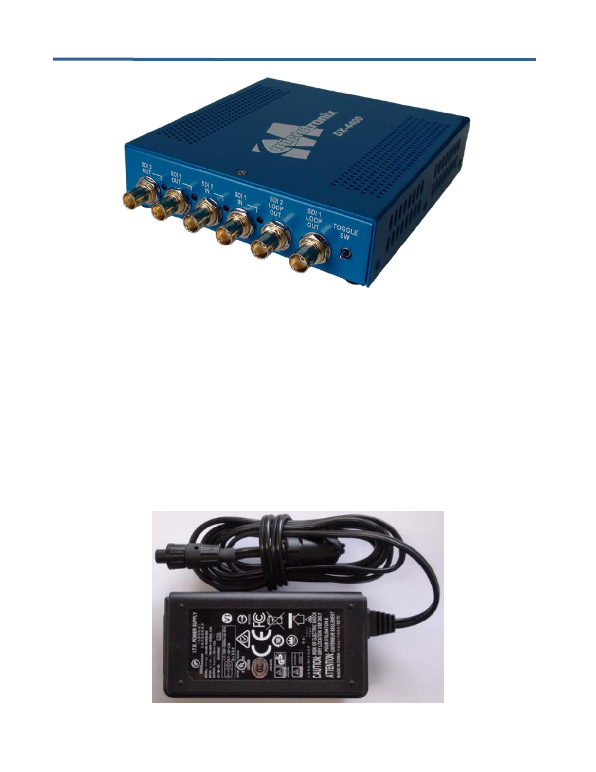
2.4 Hardware
The DX-4400 product is available in either a chassis with a 120/240VAC wall adaptor as shown in the Figures
below or optionally it can be purchased as an open-frame board for integration into an embedded video system.
Page 14
DX-4400 – 3G-SDI Text & Graphics Overlay Inserter – User Manual
Page 14 of 125
Figure 1: DX-4400 – SD/HD/2K/4K-SDI Text & Graphics Overlay Inserter Product
2.4.1 Enclosure Dimensions
The DX-4400 chassis enclosure has dimensions of (L x W x H) of 6.75" x 5.75" x 1.5" where the width dimension
applies to the ends with the connectors.
The DX-4400 OEM Board (PN: M6297-TI-2K or M6297-TI-4K) has dimensions of (L x W x H) of 6.0" x 5.25" x
1.125" where the width dimension applies to the side with the BNC connectors.
2.5 Power Requirements
The DX-4400 product draws up to a maximum of 1.5 amps from a regulated 12VDC 2.5A 30W 100-240VAC
50/60Hz power adapter.. To ensure EMC regulatory compliance, the negative (ground) input of the DC supply is
connected to frame ground.
The AC power adapter is shown in the figure below.
Figure 2: 12Vdc 2.5A 100-240VAC Power Adapter
Page 15

DX-4400 – 3G-SDI Text & Graphics Overlay Inserter – User Manual
Page 15 of 125
2.5.1 DC Power Connector
The DX-4400 product uses a chassis mounted 2-pin (male pins) secure circular bayonet locking connector made
by Switchcraft PN: 17282-2PG-300 (Digi-Key: SC1206-ND). The mating connector on the power adapter is a
Switchcraft PN: 16282-2SG-315 two-pin female socket connector (Digi-Key: SC2122-ND).
2.6 Environmental Operating Limits
The DX-4400 product is designed for the following ambient operating environment::
• Temperature Range: 0C to 40C
• Relative Humidity: 0 to 95% non-condensing.
The chassis is vented for heat dissipation and requires approximately 6" of physical clearance on the top and
vented sides to provide adequate air convection to ensure proper device cooling.
Page 16

DX-4400 – 3G-SDI Text & Graphics Overlay Inserter – User Manual
Page 16 of 125
3 Operation
3.1 Powering on the DX-4400
The DX-4400 unit operates from at 12VDC from the supplied 120/240VAC power adapter. Each time the
DX-4400 is powered on it requires the microSD Card installed in the card slot to enable it to boot the Linux
Operating System contained on the card. The unit is shipped from the factory with the micro SD Card preinstalled in the card slot.
Warning: If it is necessary to install a microSD Card into the unit, be careful when sliding the card into the card
slot so as to not misalign the card to the card slot connector. Otherwise, the card may accidently fall
inside the unit and will require the chassis to be opened to retrieve the card.
3.2 Modes of Operation
The DX-4400 product has several selectable Modes of Operation. Each mode has different capabilities and
features. The available modes are:
1) Dual Text Inserter (Dual TI). In this mode the product provides two video channels with separate text
and graphics overlays for each channel. Each channel supports the SD, HD, and 3G modes listed in the
product specifications with ancillary data pass through.
2) Low Latency Dual Text Inserter (LDual TI). In this mode the product provides two video channels with
separate text and graphics overlays for each channel without frame buffers in the path. Each channel
supports the SD, HD, and 3G modes listed in the product specifications with ancillary data pass-through.
There is no SDI alpha blending.
3) Zoom Dual Text Inserter (ZDual TI). In this mode the product provides two video channels with separate
text and graphics overlays for each channel. Each channel supports the SD, HD, and 3G progressive
modes (no interlaced or PsF modes) listed in the product specifications without ancillary data passthrough. Each channel supports separate zoom control.
4) Picture in Picture Text Inserter (PiP TI). This mode provides a single text inserter with a main input and
a secondary input. Both inputs have scaling capabilities to allow for use as Picture in Picture (PiP), split
screen or side by side configurations. The unit has a single text and graphics overlay and supports the
SD, HD, and 3G modes listed in the product specifications. Ancillary data from input 1 passes through the
unit to the output.
5) Low Latency Picture in Picture Text Inserter (LPiP TI). This mode provides a single text inserter with
less than one frame of delay from input 1 to the output. Input 1 does not support PiP or Zoom. Input 2
supports PiP and Zoom. Ancillary data is supported on Input 1.
6) Dual Link 4K Text Inserter (4K TI). The unit provides a text and graphics overlay for one channel of 4K
(Quad and 2SI mapped) video transported in the dual link modes listed in the product specifications.
Ancillary data pass through is NOT supported.
7) Low Latency Dual Link 4K Text Inserter (L4K TI). The unit provides a text and graphics overlay for one
channel of 4K (Quad and 2SI mapped) video transported in the dual link modes without frame buffers in
the video path. Ancillary data pass through is supported in this mode of operation.
8) Zoom 4K Dual Link 4K Text Inserter (Z4K TI). The unit provides a text and graphics overlay for one
channel of 4K (Quad or 2SI mapped) video transported in the dual link mode. For 2SI mapped video only,
the input can be zoomed. Ancillary data pass-through is supported in this mode of operation.
NOTE: Support for 4K video is an optional product upgrade and is not available in the base
product configuration.
Page 17
DX-4400 – 3G-SDI Text & Graphics Overlay Inserter – User Manual
Page 17 of 125
Within each mode of operation, the unit auto detects the format of the input video from the modes supported, and
outputs in the same format. Custom user configurations and parameters can be stored on the microSD Card file
system for auto restoration during power ON/OFF cycles.
The Mode of Operation can be changed by using the Set Mode (SM) Command described in § 3.7.1 Set Mode
Commands or via the Web UI as described in § 5.3.1 General Environment – Mode of Operation Page.
3.3 Default Configuration and Video Mode
The factory default startup configuration for the DX-4400 uses a database Saveset named "default" to store Fields
required to configure the unit for the default configuration. The default is to use the database on the SD flash card.
If you operate in a Mode that requires many commands – such as moving an image on the screen – you may
want to switch the Saveset to use an in-memory database to reduce flash writes. (See IM Command of Table 23:
Command Syntax for Saveset Default Values.) This will also speed up the operation.
When powered up in the factory default configuration, the unit will operate as a PiP TI and pass the primary SDI 1
video through to the two outputs with text and graphic overlay items added. The DX-4400 will automatically
output in the same video format as is detected at the SDI input.
If the input video format changes, the DX-4400 will momentarily switch off the output while the out format is
adjusted to match the input. When the input format is detected and the video (pixel) clock is locked to the source,
the video out path is enabled and the input video and ancillary data will appear at the output.
If the SDI input is disconnected, the unit continues to output in the last video format that was detected.
If there is no input signal (or if it cannot be properly detected), the DX-4400 operates in the default video mode
and outputs the overlay information on a black background. In the Dual TI, LDual TI, ZDual TI, and PiP TI
Modes, the video format will be 1920x1080p30. In the 4K TI and L4K TI Modes, the default video format will be
3840x2160p30 in quadrant mode.
3.4 OSD Layers
The DX-4400 uses a quad-core ARM Graphics Video Processor which supports two video paths shown in
Figure 3 with a graphics video layer mixed on top of each SDI video input.
Figure 3: DX-4400 Layer Order
The top layer is the ARM Graphics Overlay Video which is the output overlay generated from the ARM Graphics
Overlay Processor. This layer displays the Text, Graphic and Image Field information entered by the user using
Text, Graphic or Image Overlay Commands.
The 2nd layer is the SDI Video, and the 3rd layer is the Black Background.
The ordering of layers in the ARM video output is determined by their Z Layer number with the higher layer
numbers being at the top. If two Fields have pixels that occupy the same coordinates on the same Z-Layer, one
will overwrite the other. The Field are rendered in the order they were defined (Text first, Image second followed
by Graphic). The ID numbering assignments used for Text, Image and Graphic Fields are specific to each group.
When Graphic Fields on different Z Layers are placed at the same coordinates, they mix according to their
transparencies. When a Field item is fully visible (no alpha assignment), all content that is on the layers below it
will not be visible. When the Field is partly or fully transparent, it mixes with the layers below according to their
transparencies.
Page 18
DX-4400 – 3G-SDI Text & Graphics Overlay Inserter – User Manual
Page 18 of 125
3.5 LED Status Indicators
The location of the 5 LEDs is shown in the following two figures.
Figure 4: DC Power LED
Figure 5: SDI Input / Output Status LEDs
The operation of the SDI status LEDs is summarized in the table below.
Table 1: Description of SDI LED Status Indicators
LED
Color
Use
Description of LED Status
SDI 1 IN
Red
Valid Video
OFF: SDI 1 input has either no video, or an unsupported video format.
ON: A signal is detected on the input.
SDI 2 IN
Red
Valid Video
OFF: SDI 2 input has either no video, or an unsupported video format.
ON: A signal is detected on the input.
SDI 1 OUT
Red
Overlay Active
OFF: Arm Overlay off or not valid
ON: Arm Overlay on SDI video output 1.
SDI 2 OUT
Red
Overlay Active
OFF: Arm Overlay off or not valid
ON: Arm Overlay on SDI video output 2.
Power
Green
Power
ON: Power OK
3.6 External Control of the DX-4400
The DX-4400 has three methods for interfacing an external user to the Command Port used to control the
operation of the unit.
1) Network Control using a raw TCP/IP connection (to port 2121) over Ethernet from a Telnet or other
terminal emulation client running on a PC.
2) RS-232 Control using the DB9 connector labeled "RS-232 Control".
3) USB Serial Control using the type B USB port labeled "USB Serial Port".
Page 19

DX-4400 – 3G-SDI Text & Graphics Overlay Inserter – User Manual
Page 19 of 125
4) Web UI Control using a standard web browser and a TCP Ethernet connection. This method of control is
discussed in section (§) 5 titled Using the Web UI.
To utilize Serial Control requires the user establish a connection via either the RS232 port or the USB Serial port.
The factory default connection sets Serial Control to the RS-232 Control Port interface.
To switch Serial Control from the RS-232 Control Port to the USB Serial Port requires the user to establish a
connection to the internal Command Port (via either Network Control port or through the DB9 Serial port) and
issue a Set Mode Command to the unit per Table 6: Set Mode Command Syntax.
Alternately, the user can use Network Control via a TCP/IP connection to the Command Port since it is always
available for external user control through a TCP Ethernet connection.
Note: For the examples provided in the following sections, the Commands are executed via a Serial (RS232
or USB) connection or a Network TCP/IP connection to the Control Port of DX-4400 unit.
Warning: Only one Network Control port user connection can be active at a time.
3.6.1 Serial Control Mode of Operation
When Serial Control is used, the DX-4400 is controlled via Commands sent to the Command Port via either the
RS-232 Serial Control Port or the USB Serial Port using a terminal emulator program on a PC. Refer to
Appendix B, section Establishing RS-232 Serial Communication to a PC page 100 for the recommended settings
for the PuTTY terminal emulator.
Note: The Serial COM port of the computer connected to the DX-4400 should be configured for: 115,200
baud, 8-bit data, no parity, 1 stop bit and no XON/XOFF flow control.
The Command Port acknowledgement codes (supplied from the DX-4400 and received by the PC) are listed in
Table 2 below.
3.6.1.1 USB 2.0 to RS-232 Serial Port Adapter Kit
Since most PC no longer come with a RS-232 Serial port, the DX-4400 product is supplied with a USB 2.0 to
DB9 RS-232 Serial Port Adapter Kit (PN: 811-USB-RS232 Kit) to connect the DB9F Serial Port on the unit to a
USB 2.0 port of a PC or laptop. The Kit consists of a USB 2.0 to RS232 DB9 Serial Adapter Cable (StarTech PN:
ICUSB232V2) and a 6 foot male to female DB9 RS232 Serial cable. Refer to Appendix B titled Establishing
User Connections to the DX-4400 Product for more information.
3.6.1.2 USB Serial Port
The USB Serial Control Port can also be used to control the text overlay. The port interfaces to a PC with a
standard USB 2.0 – A to Mini-B (Male-Male) cable included with the product.
Since by default, the Serial Control Port is mapped to the RS-232 Serial port, to use the USB interface it is
necessary to establish a connection to the Command Port (via either Network Control port or through the DB9
Serial port) and issue a Set Mode command to the unit per Table 6: Set Mode Command Syntax to switch Serial
Control to the USB Serial Port. \
3.6.2 Network Control Using Raw TC/IP
The Network Control connection is used to sent commands to the DX-4400 over Ethernet, using a terminal
emulator (Telnet, PuTTY) application to TCP port number 2121. The Ethernet address is either assigned via
DHCP or by static IP address assignment (default 10.1.1.230/8)
From either a Windows command prompt or Linux command line, you can establish a Network Control user
connection to the Command Port of the DX-4400 using the following commands:
Window Client
Linux Client
Page 20

DX-4400 – 3G-SDI Text & Graphics Overlay Inserter – User Manual
Page 20 of 125
open <IP Address> 2121
telnet <IP Address> 2121
nc <IP Address> 2121
telnet <IP Address> 2121
Note: Refer to sections 3.6.3.2 or 3.6.3.3 below for information on the default static network IP address or
the DHCP assigned IP address.
TIP: To confirm the connection to the Command Port of the DX-4400, type RV to cause the unit to display
the revision of the software and the MAC & IP address.
Note: On a Windows PC, a Telnet Client is available from a Command Prompt window.
Warning: In Windows 7 and 10 the Telnet Client is turned off by default. To get more information on enabling
the Telnet Client, search in Google with the term "Enabling Telnet Client on Windows".
TIP: PuTTY is a free PC terminal emulator utility which supports Telnet, SSH and Serial connections. Refer
to section Appendix B:, titled Establishing TCP/IP Connection to the DX-4400 Product form more
information.
The Command Port acknowledgement codes (i.e. the DX-4400 response to user commands) are listed in Table 2
below.
3.6.3 Network Control Using Web UI
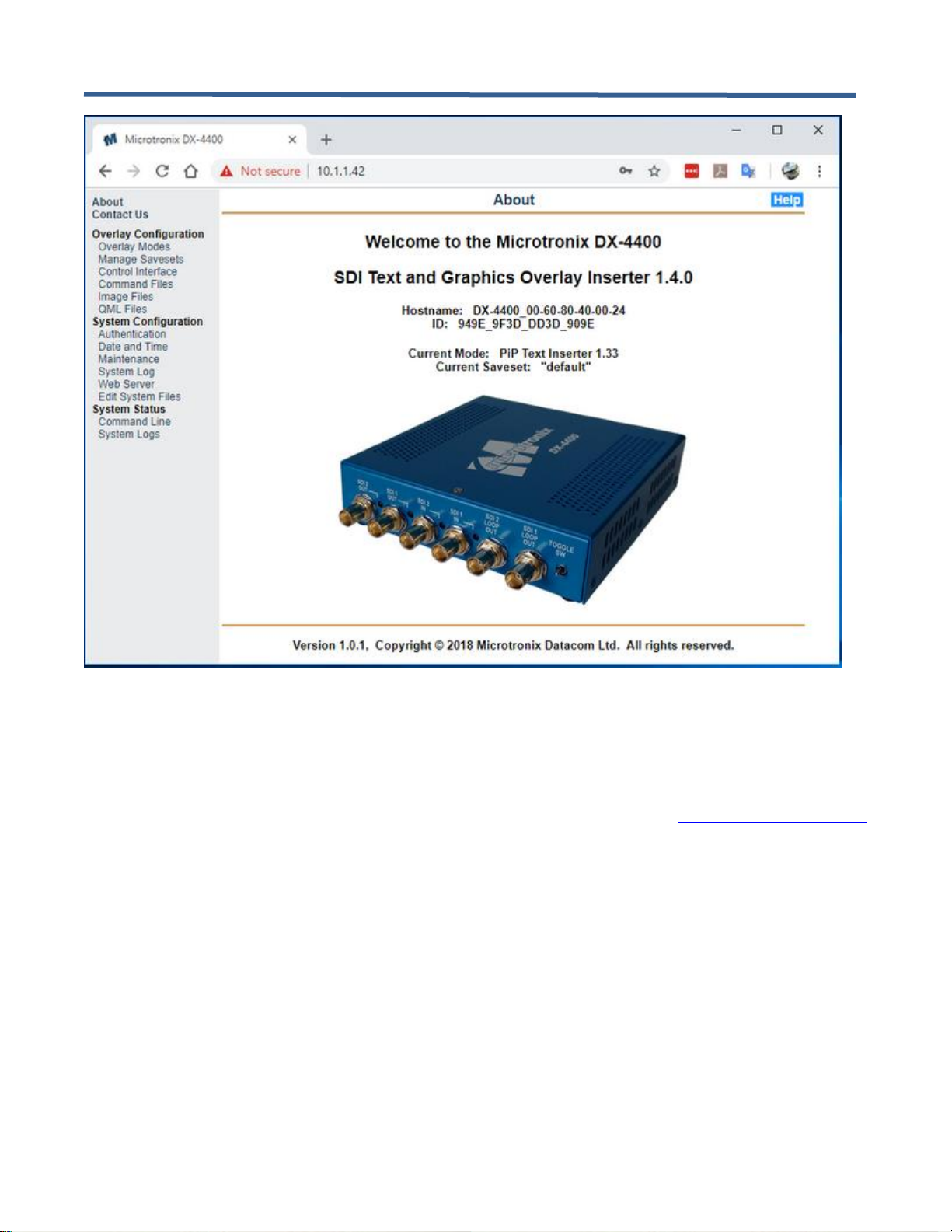
The DX-4400 supports a web server which offers the user the ability to configure, manage and maintain the unit
using a web browser. All of the features available via the Serial Control interface or the Network Control interface
(TCP/IP) are available through the Web UI.
3.6.3.1 Connecting to the Web UI
To access the Web UI is it necessary to make an http connection using the IP address by the local DHCP network
server. For example: http://10.1.1.42 (Refer to § 3.6.3.3 titled DHCP Assignment of Network IP Address below
for more information on obtaining the IP address.)
At the sign in (login) prompt enter the default Username and Password of admin and admin. The DX-4400
Web UI home page is shown below. For more information on using the Web UI refer to § 5 Using the Web UI.
Page 21
DX-4400 – 3G-SDI Text & Graphics Overlay Inserter – User Manual
Page 21 of 125
Figure 6: DX-4400 Web UI Home Page
3.6.3.2 Default Static Network IP Address
The factory default Ethernet secondary static Network IP address is 10.1.1.230. This assignment is stored in the
ethenv (Ethernet environment) system file, namely /etc/dx4400/ethenv. This file can be edited using the Web UI
under the System Configuration using the Edit System Files menu item. (See section 5.7.6 System Configuration
– Edit System Files Page for more information.)
Note: This feature is only available in software version 1.5.0 and beyond.
3.6.3.3 DHCP Assignment of Network IP Address
When connected to an Ethernet Network, the DX-4400 unit uses DHCP to acquire an IP address from the
Network. The unit self identifies to the DHCP Server as DX-4400_00-60-80-NN-NN-NN where NN represents the
digits of the MAC address that can be found on the bottom of the unit.
Using the defined name, check with your Network Administrator who will be able to supply you with the IP
address assigned by the Network DHCP Server. Alternatively, by using a Ping Command from the Command
Prompt of a PC, it should be possible to get a response from the DX-4400 unit by typing:
ping DX-4400_<mac addr>
where <mac addr> is the address of the unit. For example if the nameplate label on the DX-4400 shows MAC
Address of 00:60:80:40:00:02, then the Ping Command would be:
ping DX-4400_00-60-80-40-00-02
Page 22

DX-4400 – 3G-SDI Text & Graphics Overlay Inserter – User Manual
Page 22 of 125
If the ping does not work, to determine the assigned IP address, you can use a Serial connection to the
Command Port either through the RS-232 Control Port or the USB Serial Port. (Refer to sections above for
details). Once connected to the Command Port, use the RV command to display the IP address.
Also included on the CD is a Windows application installer ipscan25.exe (Advanced IP Scanner) that can be used
to find all the devices on the local Network. If the DHCP Server did not recognize the name given locate the
device with a MAC address starting with 00:60:80 that will be the DX-4400.
3.6.4 Serial/Network Control – Command Port Syntax
To control the operation of the DX-4400, Serial and Network Commands are sent to the Control/Command Port..
The Command structure and rules are as follows:
• The Commands consist of ASCII alpha-numeric codes and are not case sensitive. All Commands are
terminated with a carriage return (CR), a line feed (LF), or a semicolon. The use of a semicolon terminator
allows more than one command per line to improve readability of script files.
• Commands may be sent directly to the DX-4400 one character at a time using a Terminal Emulation
program running on a connected computer, or they may be developed in a text editor such as Notepad
and then uploaded to the DX-4400 by the Terminal Emulator program (example, HyperTerminal). The
second method has the advantage of allowing the commands to be saved, viewed, edited and resent.
The text editor used must save the configuration files as 8-bit ASCII data.
• Space or tab characters before a Command or trailing a Command are ignored, as are spaces or tabs
separating parameters within a Command.
• ASCII string parameters are delimited with quotation marks. If a quotation mark or backslash character is
required within a string (for example to display as part of a text overlay), then it must be preceded by a
backslash character.
• Valid and invalid Commands are acknowledged with a ‘+’ and ‘-’ response respectively. Carriage return,
line feed, or semicolon characters without a preceding command are acknowledged with a ‘*’.
• The Apostrophe (‘) character (when found outside of a quoted string) indicates that the remainder of the
current line is a comment and will be ignored. The use of comment characters allows script files
containing comments to be sent to the DX-4400 by a terminal program without generating error
responses.
• The Command Codes are extensible, additional commands and functionality can be added to the product
as required. Contact Microtronix sales or technical support (support@microtronix.com) with your
requirements.
Note: The Web UI can be used as an alternate user interface and provides a higher level of abstraction
minimizing some of the need to learn the command line syntax.
The Command Port acknowledgement codes are listed in the table below.
Table 2: Command Port Acknowledgement Codes
Response Code
Description
+
Valid command received
-
Invalid command received
*
Valid CR, LF, semicolon, or comment line received
Page 23
DX-4400 – 3G-SDI Text & Graphics Overlay Inserter – User Manual
Page 23 of 125
3.6.5 Manual Mode of Operation
The operation of the DX-4400 can optionally be configured to be controlled using Command strings assigned to
the momentary bi-directional Toggle Switch and the DIP Switches using User Defined Command as described in
Table 3 and Table 4 below.
In the Manual Mode operational settings can be controlled by both the DIP Switch and Serial commands sent to
the Command Port (see § 3.6.4 Serial/Network Control – Command Port Syntax). In the case where a serial
command is used to change a setting that is also controlled from the DIP Switch, the setting of the Switch will be
temporally overridden. Changing the position of the Switch will return control of the setting to the DIP Switch.
The functions of the DIP and Toggle Switch are user programmable by User Defined Commands per § 3.12 User
Defined Commands and via the Web UI per § 5.5 Web UI – User-defined Commands Menu. The following section
describes the factory default configuration.
3.6.5.1 Toggle Switch Settings
The Toggle Switch settings are user configurable to enable functions via Command Strings. The Command
assignments are listed in Table 3 below.
Table 3: Operation of 2-Position Momentary Toggle Switch
Switch Movement
Description
Toggle Left (TL)
Command strings defined by UDTL. (See Table 24)
Toggle Right (TR)
Command strings defined by UDTR. (See Table 24)
3.6.5.2 DIP Switch Settings
The DIP switches can be grouped together to provide more options than string IDs 0 and 1. When the DIP
switches are grouped the least significant digit is always the highest numbered DIP switch in the group. The
Command assignments are listed in Table 4 below.
Table 4: Operation of 4-Postion DIP Switch
DIP Switch
Description
DIP Switch 1
Command strings defined by UDD1. (See Table 24)
DIP Switch 2
Command strings defined by UDD2. (See Table 24)
DIP Switch 3
Command strings defined by UDD3. (See Table 24)
DIP Switch 4
Command strings defined by UDD4. (See Table 24)
3.7 Setting DX-4400 Mode of Operation
The DX-4400 product has several Modes of Operation with each mode offering different functions and operational
features as described in Table 5 below. Since some features are specific to a Mode of Operation, not all user
commands (used to control the feature) are applicable to all modes. For example, the PiP / Zoom commands
function only in the PiP TI Mode. Therefore, in other modes these commands have no effect.
Page 24

DX-4400 – 3G-SDI Text & Graphics Overlay Inserter – User Manual
Page 24 of 125
The Modes of Operation of the DX-4400 is configured by the user using the Set Mode (SM) Command are
described in the Table 6 below.
Table 5: DX-4400 Modes of Operation
Mode
Description
Dual Text Inserter
(Dual TI)
The DX-4400 functions as a Dual Channel SDI Text Inserter (Dual TI ).
➢ An overlay layer is added to the video on Input 1. The output is available on Output 1.
➢ A different overlay layer is added to the video on Input 2 and the output is available
on Output 2.
➢ Input and 1 and 2 both pass all ancillary data including audio from the SDI input to the
corresponding SDI output.
➢ Zoom and PiP functions are not supported.
➢ All the supported video modes are available except for the 4K modes. Each output
will automatically adjust mode to match the signal on the corresponding input. Refer
to the Video Input Formats list (under § 1.1 Supported Functionality) for the
supported modes.
Low Latency
Dual Text Inserter
(LDual TI)
The DX-4400 functions as a low Latency Dual Channel SDI Text Inserter (LDual TI).
The delay through the video path is less than one frame.
➢ An overlay layer is added to the video on Input 1. The output is available on Output 1.
➢ A different overlay layer is added to the video on Input 2 and the output is available
on Output 2.
➢ Input and 1 and 2 both pass all ancillary data including audio from the SDI input to the
corresponding SDI output.
➢ Zoom, Alpha and PiP functions are not supported.
➢ All the supported video modes are available except for the 4K modes. Each output
will automatically adjust mode to match the signal on the corresponding input. Refer
to the Video Input Formats list (under § 1.1 Supported Functionality) for the supported
modes.
Zoom Dual Text
Inserter
(ZDual TI)
The DX-4400 functions as a Dual Channel SDI Text Inserter (ZDual TI)with zoom on
both video paths. No ancillary data is passed through.
➢ An overlay layer is added to the video on Input 1. The output is available on Output 1.
➢ A different overlay layer is added to the video on Input 2 and the output is available
on Output 2.
➢ PiP functions are not supported.
➢ All the supported video modes are available except for interlaced and 4K modes.
Each output will automatically adjust mode to match the signal on the corresponding
input. Refer to the Video Input Formats list (under § 1.1 Supported Functionality) for
the supported modes.
Text Inserter
with PiP
(PiP TI)
The DX-4400 functions as a Text Inserter with PiP (PiP TI)supporting two inputs, one
overlay, and two identical outputs.
➢ Input 1 is the main input. The product automatically adjusts the output to match the
video detected on Input 1. All ancillary data (including audio) from input 1 is
transported to both outputs.
➢ Input 2 is a secondary input that is typically used for a PiP display. Ancillary data from
input 2 is discarded. Input 2 can be a different resolution or frame rate than Input 1,
but if Input 1 is progressive, then Input 2 must be progressive, and if Input 1 is
interlaced or PsF,, then Input 2 must be interlaced or PsF.
➢ Both input 1 and input 2 can be down scaled and clipped, allowing for display as Side
by Side, or Split screen in addition to PiP display.
➢ All the supported video modes are available except for the 4K modes. Refer to the
Video Input Formats list (under § 1.1 Supported Functionality) for the supported
modes.
Page 25

DX-4400 – 3G-SDI Text & Graphics Overlay Inserter – User Manual
Page 25 of 125
Mode
Description
Dual Link 4K Text
Inserter
(4K TI)
The DX-4400 functions as a single channel, 4K Text Inserter (4Kl TI). Video inputs and
outputs operate as SDI Dual Links with each port operating at 3 GB/s supporting 4K video
at frame rates up to 30 fps.
➢ 3840x2160 and 4096x2160 resolutions are supported.
➢ Ancillary data from the inputs is discarded.
➢ Zoom and PiP functions are not supported.
➢ If you switch into 4K mode without a having a 4K IP Core License File installed, the
video is disabled.
Low Latency Dual
Link 4K Text
Inserter
(L4K TI)
The DX-4400 functions as a single channel, 4K Text Inserter (L4K TI). Video inputs and
outputs operate as SDI Dual Links with each port operating at 3 GB/s supporting 4K video
at frame rates up to 30 fps. The delay is less than one frame.
➢ 3840x2160 and 4096x2160 resolutions are supported.
➢ Ancillary data and audio from the inputs is transported to the outputs.
➢ Zoom and PiP functions are not supported.
➢ If you switch into Low Latency 4K mode without a having a 4K License File installed,
the video is disabled.
Zoom Dual Link 4K
Text Inserter
(Z4K TI)
The DX-4400 functions as a single channel, 4K Text Inserter (Z4K TI). Video inputs and
outputs operate as SDI Dual Links with each port operating at 3 GB/s supporting 4K video
at frame rates up to 30 fps.
➢ 3840x2160 and 4096x2160 resolutions are supported.
➢ Ancillary data and audio from the inputs is transported to the outputs.
➢ Text overlay is supported for 2SI and Quad mapped video.
➢ High magnification zoom is supported for 2SI mapped video only.
If you switch into this mode without a having a 4K License File installed, the video is
disabled.
Low Latency Text
Inserter with PiP
(LPiP TI)
The DX-4400 functions as a Text Inserter with PiP (LPiP TI)supporting two inputs, one
overlay, and two identical outputs.
➢ Input 1 is the main input. The product automatically adjusts the output to match the
video detected on Input 1. All ancillary data (including audio) from input 1 is
transported to both outputs. This input has a latency of less than 1 frame from input 1
to output. Zoom and PiP functions are not available.
➢ Input 2 is a secondary input that is typically used for a PiP display. Ancillary data from
input 2 is discarded. Input 2 can be a different resolution or frame rate than Input 1,
but if Input 1 is progressive, then Input 2 must be progressive, and if Input 1 is
interlaced or PsF, then Input 2 can be progressive, interlaced or PsF.
➢ Input 2 can be down scaled and clipped.
➢ Input two can support high magnification zoom with a latency of 2-3 frames or can
have latency 1-2 frames with zoom limits of 100% for 3G, 150% for HD and 300% for
SD modes.
➢ All the supported video modes are available except for the 4K modes. Refer to the
Video Input Formats list (under § 1.1 Supported Functionality) for the supported
modes.
Notes:
1) The Low Latency mode decreases the frame delay and is described in Section 3.9.6 Video Buffering and
Frame Delay.
2) The REM Command can be used to display the current Mode of Operation.
3.7.1 Set Mode Commands
The Set Mode (SM) commands are used to select the Mode of Operation for the DX-4400 product and optionally
assign the Serial Command Port to either the RS-232 Serial port or the USB Serial port.
Page 26

DX-4400 – 3G-SDI Text & Graphics Overlay Inserter – User Manual
Page 26 of 125
The SM command takes up to two arguments: the first is the mode to switch the DX-4400 into and the second is
to assign the Serial Command Port to use for Command parsing. Changing between Modes takes several
seconds during which time the output video is interrupted and no additional commands can be sent to the unit.
Table 6: Set Mode Command Syntax
Parameters
Description of Command
SM – Sets the Mode of Operation where <Serial> is optional and can be either RS232 or USB
SM DUAL <Serial>
Selects the Dual Text Inserter Mode (Dual TI)
SM LDUAL <Serial>
Selects the Low Latency Dual Text Inserter Mode (Dual TI)
SM ZDUAL <Serial>
Selects the Dual Text Inserter Mode with Zoom (Dual TI)
SM PIP <Serial>
Selects the PiP Text Inserter Mode (PiP TI)
SM 4K <Serial>
Selects the 4K Text Inserter Mode (4K TI)
SM L4K <Serial>
Selects the Low Latency 4K Text Inserter Mode (4K TI)
SM Z4K <Serial>
Selects the Zoom 4K Text Inserter Mode (Z4K TI)
SM LPIP <Serial>
Selects the Low Latency PiP Text Inserter Mode (LPiP TI)
SM <serial>
Assigns location of the Serial user connection of the Command Port
Where <Serial> can be either RS232 or USB
SM I
Initialize Saveset Database to factory defaults
SM
Restart the unit no changes
Notes:
1) The factory default configuration assigns the Serial Control Port to the RS232 Port (instead of the USB
Serial Port).
2) The commands accept the shortest unique string. For example, it is acceptable to specify SM LD instead
of SM LDUAL.
3) Use of the Set Mode (SM) Command does not clear the user information stored in the Saveset Database.
3.7.1.1 Example - Set Mode Command
To set the DX-4400 to operate as a PiP Text Inserter and to change the Serial Command port from the RS-232
Port (the factory default assignment) use the following command via the Control Port (Serial or Network):
SM PIP USB
3.8 Overview of Overlay Fields
To generate a Graphic Overlay / On Screen Display (OSD), Fields are defined to specify the parameters and
features (attributes) of each object displayed. Four types of Overlay Fields are available:
1) Text Fields – display single line of ASCII characters and are defined using the ‘T’ Command.
2) Graphic Fields – displays shapes (Circle, Ellipse, Line, and Rectangle) and defined by the
‘G’ Command.
3) Image Fields – display an image from a user supplied file stored on the DX-4400 and are defined by the
"I" Command.
4) QML Fields – run QML Script files stored on the DX-4400 and are defined by the "Q" Command.
All Fields are mixed together taking into account their transparency and position in the layer stack up (defined by
the Z parameter of the field) to generate a single blended Overlay Layer that is mixed on top of the SDI input
video channels.
Page 27

DX-4400 – 3G-SDI Text & Graphics Overlay Inserter – User Manual
Page 27 of 125
The video output of the Overlay Layer is updated by the ARM rendering the graphics to the video frame buffer.
The amount of time required to render the graphic items is dependent on the number of items on the Overlay
Layer.
All Overlay Fields are associated with a Saveset stored in the system Configuration Database. The DX-4400
always has a Saveset named "default" which cannot be deleted. You can create/delete your own named
Savesets allowing the user to define different Overlay Configurations. When you delete a Saveset, all the Fields
are removed from the overlay display.
For each Saveset, the Fields are numbered 1 through 999 by the ID parameter. Each of the four types of Fields
(Text, Graphics, Images and QML) use separate ID values.
The Toggle and DIP Switch User Defined Command are numbered 1 through 15 by the ID parameter. (Refer to
Table 24: Toggle Switch – User Defined Command Syntax and Table 25: DIP Switch User Defined Command
Syntax for more information.)
By default, all Graphic Fields are visible and have default parameters (attribute settings). For example, the
following Graphic Field Command draws a simple rectangle positioned with the top left corner at 100, 100. The
rectangle has a length of 400 (X distance) and height of 200 (Y distance). The rectangle has a default border
Color of white with white fill and no transparency.
G ID=1 S=rectangle X=100 Y=100 L=400 H=200 ‘add user comment if required
Each Graphic Field can be turned on or off independently by the Visibility parameter V taking a value of YES or
NO. For example, to turn off the visibility of the above rectangle enter the command.
G ID=1 V=no ‘Turn graphic ID 1 visibility OFF
A Graphic Field is updated when a change occurs.
3.8.1 Coordinate System and Field Position
Each Overlay Field has three position coordinates referred to as X, Y and Z with a default value of zero. One or all
of these coordinates may be used when defining a Field.
The coordinate system designates x=0000 and y=0000 as the top-left corner of the overlay for all video formats.
This is the default position for all Fields.
The maximum value for the x and y coordinates is located at the bottom-right corner of the frame.
• For Digital Cinema 2160p video formats the bottom-right corner is at coordinates x=4095, y=2159.
• For UHD 2160p video formats the bottom-right corner is at coordinates x=3839, y=2159.
• For 1080p, 1080i, and 1080PsF formats the bottom-right corner is at coordinates x=1919, y=1079.
• For 720p video formats the bottom-right corner is located at x=1279, y=719.
• For NTSC video format the coordinates are x=719, y=485, and for PAL format x=719 and y=575.
Note: Some monitors will not display the entire video frame, particularly when operating in NTSC or PAL
modes. Graphic Fields placed close to the edges of the overlay may not be visible on some monitors.
Any Field or portion of a Field that extends beyond the edges of the Overlay will not be visible.
The Z position allows you to stack the Fields on top of each other. If the alpha value is other than zero the Fields
will be blended with the higher Z value being at the top.
Note: By default, all fields are at Z position 0, but fields with higher ID numbers are placed above fields with
lower ID numbers and will be blended above them.
Note: When Fields of different types overlap, and the Fields have the same Z layer (or no Z layer has been
defined) the Fields may not appear in the same order after power cycling the DX-4400. This occurs
because as Fields are being defined, they are drawn in the order the commands are given to the
DX-4400, but at power up the Fields are drawn by their type and in order of ascending ID numbers
with Text Fields drawn first, followed by Image Fields, followed Graphic Fields, and then QML Fields.
Page 28

DX-4400 – 3G-SDI Text & Graphics Overlay Inserter – User Manual
Page 28 of 125
To avoid this behaviour, it is good practice to always define the Z position of objects when they
overlap.
3.8.2 Color and Transparency
Text and Graphic Fields have a Color specified by SVG Color Keyword Name assignments – as defined by the
Scalable Vector Graphics (SVG) Specification – (see: http://www.december.com/html/spec/colorsvgsvg.html for a
color chart) or by using Red, Green, and Blue Components in the range from 0 to 255.
There are two Color components for Graphic shapes: (1) the Foreground Color used for fill and (2) the Border
Color used for the outline. The default Color is white (R255, G255, and B255).
For example, to change the fill Color of Graphic Field one to darkgoldenrod you can use either of the following
Commands:
G ID=1 FC=darkgoldenrod
G ID=1 FC=#184134011
The Foreground color has a Transparency property that can be controlled using the FA=aaa to set the Alpha
value for mixing with underlying layers. Setting the Alpha value to 0 sets the foreground color to be fully visible
and no content on lower video layers will be visible through the Color. An Alpha of 255 sets the Color fully
transparent. At this setting the color will be completely invisible.
For example: sending a G ID=1 FA=192 command makes Graphic Field 1 approximately 75% transparent.
3.8.3 Text Overlay Fields
Each Text Field has a Background color that is used for the background of Text Fields. Background color is set in
the same way as foreground Color, except the command used is BC=darkgoldenrod. The transparency for the
Background color can controlled using the BA=aaa command to set the Alpha value from 0 to 255 (the default is
fully transparent). A summary of the Text Overlay Commands is given in Table 8: Text Overlay Command Syntax
below.
The following example Commands set the Foreground Color to Yellow and the Background Color to blue for Text
Field 1 with partial (50%) visibility:
T ID=1 "Text: Yellow text on blue background, Alpha = 000"
T ID=1 FC=yellow FA=128 BC=blue BA=0
Notes:
1) When the text is partially transparent, its apparent color will be determined by the text color, the background
Color and the visibilities of the text and background.
2) When a text background is displayed, the total number of color / transparency combinations is limited. Small
changes in the color or transparency parameters of the text or background may not change the appearance
For each Text Field, a font / size combination can be selected using the T ID=1 N="Font Name" P=xxx command to
select one of the font options in Table 7: Text Font and Symbol Font Attributes.
Each Text Field can be turned on or off independently by the Visibility parameter V taking a value of YES or NO.
For example, to turn off the visibility of the above text enter the command.
T ID=1 V=no ‘Turn Text ID 1 visibility OFF
After defining one or more Text Fields, all of the assigned Text Field strings can be listed using the follow Report
Text Field Command (from Table 27: Miscellaneous Control Port Commands):
RET
3.8.3.1 Available Text and Symbols Available Font & Symbol
The attributes of the text ASCI fonts and the extended font symbols available in the DX-4400 are listed in the
Table 7 below.
Page 29
DX-4400 – 3G-SDI Text & Graphics Overlay Inserter – User Manual
Page 29 of 125
Table 7: Text Font and Symbol Font Attributes
Font Name
Fixed
Width
Font Name
Fixed
Width
Bitstream Charter
DejaVu Serif
Bitstream Vera Sans
Luxi Mono
YES
Bitstream Vera Sans Mono
YES
Luxi Sans
Bitstream Vera Serif
Luxi Serif
Courier
YES
Utopia
Courier 10 Pitch
YES
Wingdings
Cursor
Wingdings 2
DejaVu Sans
Wingdings 3
DejaVu Sans Mono
YES
The default Saveset font is DejaVu Sans. The default font can be changed in a Saveset using D N="Font Name"
The default pixel height and font attributes such as bold can also each be set using the D P=40 SB=YES (Default
Pixel and Set Bold Commands) for the Saveset.
3.8.3.2 Text Overlay Command Syntax
The command line syntax used for the Text Overlay Commands is listed in the table below.
Table 8: Text Overlay Command Syntax
Parameters
Description of Command Syntax
T – Identifies a Text Command string to the Command Port parser
ID=
This is a unique ID number (1-999) that identifies the Text Field and must be the first
parameter in the list
IDR=
This functions the same as the ID parameter but if the value exists the X, Y, Z, etc parameters
are reset to default.
DELETE
Deletes the user defined Text Field specified by the ID number.
Command parsing stops, no other arguments are checked.
Example: T ID=1 DELETE
"Text String"
Text to overlay on the screen.
The backslash character '\' is an escape character that allows you to insert the '"' or '\'
character into the string. The length of the string is restricted to command buffer length (1024)
minus the overhead of the surrounding '"' (quotation marks), escape characters and the T ID=x
minimum identifier.
X=
Sets the X coordinate for the top left corner for the text. The default value is 0.
Y=
Sets the Y coordinate for the top left corner for the text. The default value is 0.
Z=
Sets the Z coordinate for the text which is used to determine the layer ordering for
transparency. The layer ordering is from zero (the bottom of the stack) to the highest Z value
being the top of the stack. The default value is 0.
AA=
Enable or disable Anti-Aliasing. It takes YES or NO as an argument.
Page 30

DX-4400 – 3G-SDI Text & Graphics Overlay Inserter – User Manual
Page 30 of 125
Parameters
Description of Command Syntax
AP=
Sets the Anchor point for the field.
The locations are TL (Top Left), TR (Top Right), BL (Bottom Left), BR (Bottom Right) or CT
(Center). The default is TL.
R=
Rotation of the text with zero being horizontal.
Positive rotations move clockwise and negative rotations move counter clockwise. The default
value is 0.
FC=
Sets the foreground Color for the text. The default color is white.
FA=
Sets the Alpha value for the Foreground Color.
The range is from 0 to 255 with 0 being opaque and 255 being full transparent. The default is
0.
BC=
Sets the Background Color for the text. The default color is black.
BA=
Sets the Alpha value for the Background Color. The range is from 0 to 255 with 0 being
opaque and 255 being full transparent. The default is 255.
N=
Font Name to use for the text. If the font name contains spaces the name must be enclosed in
'"'. The default font is DejaVu Sans.
NOTE: Although the Text Command will accept any case and abbreviation, if the Web UI
interface is used to edit the Text Commend string, the UI will only recognize the full font name.
SB=
Set font style Bold.
It takes YES or NO as an argument. It accepts the shortest unique argument. The default is
NO.
SI=
Set font style Italic.
It takes YES or NO as an argument. It accepts the shortest unique argument. The default is
NO.
SU=
Set font style underline. It takes YES or NO as an argument. It accepts the shortest unique
argument. The default is NO.
SS=
Set font Style strikeout. It takes YES or NO as an argument. It accepts the shortest unique
argument. The default is NO.
SO=
Set font style overline. It takes YES or NO as an argument. It accepts the shortest unique
argument. The default is NO.
P=
Set font Pixel size. The default value is 12.
O=
Set whether the Overlay text is on video path one or two. The default value is 1.
V=
Sets whether the text is visible or not. It takes YES or NO as an argument. It accepts the
shortest unique argument. The default is YES.
Notes:
1) The Visible YES/NO Command can be used to turn display of the Text Field ON and OFF.
2) Once the font style and display assignments for the Text Field have been set, the text can be changed
without re-entering the font style and display assignments.
3.8.3.3 Example: Text Drawing Style Options
The following text listing of commands demonstrate some of the Text Drawing Style options of the DX-4000:
Page 31

DX-4400 – 3G-SDI Text & Graphics Overlay Inserter – User Manual
Page 31 of 125
' Example: Text Drawing Style options
T ID=1 "Green text, default location, default Font (DejaVu)" FC=GREEN
T ID=2 "Red text, -90 degrees Rotation" FC=RED R=-90 x=1850 y=1000
T ID=3 "Red text, 90 degrees Rotation" FC=RED R=90 x=1850 y=80
T ID=4 FC=GREEN BC=WHITE BA=0 x=0 y=75
T ID=4 "Green text with opaque white background"
T ID=5 FC=GREEN BC=WHITE BA=128 x=0 y=150
T ID=5 "Green text with 50% transparent white background"
T ID=6 FC=GREEN BC=WHITE BA=128 FA=128 x=0 y=225
T ID=6 "Green text and white background both 50% transparent"
T ID=10 "Default Font and Style" x=0 y=400 SB=No
T ID=11 "Default Font with Bold" x=0 y=500 SB=yes
T ID=12 "Default Font with Italic" x=0 y=600 SI=yes
T ID=13 "Default Font with Underline" x=0 y=700 SU=yes
T ID=14 "Default Font with Strikeout" x=0 y=800 SS=yes
T ID=15 "Default Font with Overline" x=0 y=900 SO=yes
T ID=21 "45 degrees counter clockwise" x=800 y=900 FC=yellow R=-45.0
T ID=22 "30 degrees counter clockwise" x=825 y=940 FC=yellow R=-30.0
T ID=23 "15 degrees counter clockwise" x=850 y=975 FC=yellow R=-15.0
Note: This example assumes a video resolution of 1920x1080.
Figure 7: Examples of the DX-4400 Text Drawing Styles
3.8.3.4 Example: Sample of DX-4400 Font Styles
' Example: Sample of DX-4400 Font Styles
T ID=1 "Bitstream Charter" N="Bitstream Charter" y=0
T ID=21 "ABCDEFGHIabcdeghif012345678" N="Bitstream Charter" y=0 x=950
T ID=2 "Bitstream Vera Sans" N="Bitstream Vera Sans" y=75
T ID=22 "ABCDEFGHIabcdeghif012345678" N="Bitstream Vera Sans" y=75 x=950
T ID=3 "Bitstream Vera Sans Mono" N="Bitstream Vera Sans Mono" y=150
T ID=23 "ABCDEFGHIabcdeghif012345678" N="Bitstream Vera Sans Mono" y=150 x=950
T ID=4 "Bitstream Vera Serif" N="Bitstream Vera Serif" y=225
T ID=24 "ABCDEFGHIabcdeghif012345678" N="Bitstream Vera Serif" y=225 x=950
T ID=5 "Courier" N="Courier" y=300
T ID=25 "ABCDEFGHIabcdeghif012345678" N="Courier" y=300 x=950
T ID=6 "DejaVu" N="DejaVu" y=375
T ID=26 "ABCDEFGHIabcdeghif012345678" N="DejaVu" y=375 x=950
Page 32

DX-4400 – 3G-SDI Text & Graphics Overlay Inserter – User Manual
Page 32 of 125
T ID=7 "DejaVu Sans" N="DejaVu Sans" y=450
T ID=27 "ABCDEFGHIabcdeghif012345678" N="DejaVu Sans" y=450 x=950
T ID=8 "DejaVu Sans Mono" N="DejaVu Sans Mono" y=525
T ID=28 "ABCDEFGHIabcdeghif012345678" N="DejaVu Sans Mono" y=525 x=950
T ID=9 "DejaVu Serif" N="DejaVu Serif" y=600
T ID=29 "ABCDEFGHIabcdeghif012345678" N="DejaVu SSerif" y=600 x=950
T ID=10 "Luxi Mono" N="Luxi Mono" y=675
T ID=30 "ABCDEFGHIabcdeghif012345678" N="Luxi Mono" y=675 x=950
T ID=11 "Luxi Sans" N="Luxi Sans" y=750
T ID=31 "ABCDEFGHIabcdeghif012345678" N="Luxi Sans" y=750 x=950
T ID=12 "Luxi Serif" N="Luxi Serif" y=825
T ID=32 "ABCDEFGHIabcdeghif012345678" N="Luxi Serif" y=825 x=950
T ID=13 "Utopia" N="Utopia" y=900
T ID=33 "ABCDEFGHIabcdeghif012345678" N="Utopia" y=900 x=950
Note: This example assumes a video resolution of 1920x1080.
Figure 8: Examples of the DX-4400 Font Styles
3.8.4 Graphic Overlay Fields
A Graphic Field has a shape assignment which defines what is drawn. The current shape assignments are:
1 – Rectangle
3 – Circle
4 – Ellipse
5 – Line
The parameters for the Graphic Fields have different functions depending on the type of shape being used. Each
field type is described further below. A summary of the Graphic Overlay Field command is given in Table 9:
Graphic Overlay Command Syntax shown below.
3.8.4.1 Rectangle Shapes
Rectangle Shapes are used to display a rectangle that can be either open or filled. The rectangle is drawn from
the top left corner at coordinate X, Y with a height and length.
A rectangle may be drawn with or without an outline. The outline is located around the perimeter of the rectangle
and is drawn with the outline color (as specified by the
OC=white
parameter). The outline has a width in pixels
that is specified in the outline width parameter (
OW=width
) of the Graphic Field. The default line width is 1 pixel. If
Page 33

DX-4400 – 3G-SDI Text & Graphics Overlay Inserter – User Manual
Page 33 of 125
the line width is large, the entire interior of the rectangle may be part of the outline region. The outline width
expands around the perimeter of the rectangle. For example, if the width is 4 pixels, 2 pixels will be inside the
rectangle and 2 pixels will be outside the rectangle. When the outline width is set to zero there is no outline. When
the outline is transparent the fill Color will be seen in part of the outline.
The Fill Color parameters are set by the FC=white and FA=nnn.
3.8.4.2 Example of Drawing an Ellipse.
The following Rectangle Field Display Command string will draw a blue rectangle with a green outline:
G ID=1 S=rectangle X=100 Y=100 H=880 L=1720 FC=blue FA=80 OC=green OA=60 OW=4
3.8.4.3 Circle and Ellipse Shapes
The circle and ellipse shapes are very similar. The ellipse uses the height and length to determine the proportions
and the circle uses only the length.
The X, Y anchor location is set in the center of the circle and ellipse
The outline width parameter sets the width of the outline around the circle or ellipse.
3.8.4.3.1 EXAMPLE OF DRAWING AN ELLIPSE.
The following Ellipse Field Display Command string will draw a blue ellipse with a green outline:
G ID=1 S=ellipse X=100 Y=100 H=80 L=200 FC=blue FA=80 OC=green OA=60 OW=4
3.8.4.4 Line Shape
The Line Shape starting position is at X, Y with the end point being specified by the length (L) and the width (W)
specified by the height (H) starting from a specified X,Y coordinate position.
. The Line Shape has no outline that surrounds it. Lines can have an end cap which can be flat or round. Lines
are always drawn horizontally left to right with a rotation angle of zero degrees. To draw a vertical line you would
rotate the line 90 degrees which can be positive or negative. Positive rotations are clockwise.
3.8.4.4.1 EXAMPLE OF DRAWING A LINE
The following Line Field Display Command string will draw a vertical line:
G ID=1 S=line X=400 Y=200 H=4 L=600 R=90 FC=crimson
3.8.4.5 Graphic Overlay Command Syntax
The command line syntax used for Graphic Overlay Commands is listed in the table below.
Page 34

DX-4400 – 3G-SDI Text & Graphics Overlay Inserter – User Manual
Page 34 of 125
Table 9: Graphic Overlay Command Syntax
Parameters
Description of Command Syntax
G – Identifies a Graphic Command string to the Command Port parser
ID=
This is a unique ID number (1-999) that identifies the Graphic Field and must be the first
parameter in the list.
IDR=
This functions the same as the ID parameter but if the value exists the X, Y, Z, etc
parameters are reset to default.
DELETE
Deletes the user defined Graphic Field specified by the ID number. Command parsing
stops at the end of the command, no other arguments are checked. Example: G ID=1
DELETE
S=
Identifies the Shape is to be drawn. Acceptable values are:
rectangle
circle
ellipse
line
The argument will accept the shortest unique string – such as r for rectangle.
The default value is rectangle.
X=
Sets the X coordinate for the top left corner for the rectangle/line shape and the center of
the circle/ellipse shape. The default value is 0.
Y=
Sets the Y coordinate for the top left corner for the rectangle/line shape and the center of
the circle/ellipse shape. The default value is 0.
Z=
Sets the Z coordinate for the shape which is used to determine the layer ordering for
transparency. The layer ordering is from zero (the bottom of the stack) to the highest Z
value being the top of the stack. The default value is 0.
AA=
Enable or disable Anti-Aliasing. It takes YES or NO as an argument.
AP=
Sets the Anchor point for the field.
The locations are TL (Top Left), TR (Top Right), BL (Bottom Left), BR (Bottom Right) or
CT (Center). The default is TL.
R=
Rotation of the shape with zero being horizontal. Positive rotations move clockwise and
negative rotations move counter clockwise. The default value is 0.
L=
Length is the horizontal distance for shapes. For circles and ellipses the distance is from
the center so it will be twice the length wide. The default value is 200.
H=
Height is the vertical-distance for shapes. Circles do not use the height argument. For
ellipses the distance is from the center point so it will be twice as high.
The default value is 100.
F=
Sets whether the shape is filled or not except for lines.
It takes YES or NO as an argument. It accepts the shortest unique argument. The default
is YES.
FC=
Sets the foreground Color for the shape.
For lines this is the Color of the line.
For rectangles, circles and ellipses this is the fill Color. The default is white.
FA=
Sets the Alpha value for the foreground Color.
The range is from 0 to 255 with 0 being opaque and 255 being full transparent. The
default is 0.
OC=
Sets the outline Color for rectangles, circles and ellipses. The default value is white.
OA=
Sets the Alpha value for the outline Color. The range is from 0 to 255.
The default value is 0.
OW=
Set the Outline Width for rectangles, circles and ellipses. The default value is 1.
Page 35

DX-4400 – 3G-SDI Text & Graphics Overlay Inserter – User Manual
Page 35 of 125
Parameters
Description of Command Syntax
EC=
Sets the end cap as flat or round for lines. The default value is round.
O=
Set whether the graphi Overlay is on video path one or two. The default value is 1.
V=
Sets whether the shape is visible or not.
It takes YES or NO as an argument. It accepts the shortest unique argument. The default
is YES.
Note: The Visible YES/NO Command can be used to turn display of the Graphic Field ON and OFF.
3.8.5 Image Overlay Fields
Each Image Field has a Background Color and Transparency attribute that is used to control the appearance of
the graphical image.
The Background Color of the Image Field is set in the same way as for the Foreground Color, except the
command used is BC=darkgoldenrod
The Transparency attribute for the background Color can controlled using the BA=aaa command which sets the
alpha value from 0 to 255 (the default is fully transparent).
Each Image Field has a X, Y, Z position, can be rotated, scaled and the transparency adjusted. If just the file
name is specified, the system looks for the file in /usr/local/graphics/. To specify a different location the full path
name must be supplied.
The Image Fields Commands are listed in Table 11: Image Field Overlay Command Syntax below.
3.8.5.1 Image Field File Formats
Image Fields can overlay the file types listed in the table below.
Table 10: Supported Image Formats
Format
Description
BMP
Windows Bitmap
JPG
Joint Photographic Experts Group
JPEG
Joint Photographic Experts Group
PNG
Portable Network Format
PBM
Portable Bitmap
PGM
Portable Graymap
PPM
Portable Pixmap
XBM
X11 Bitmap
XPM
X11 Pixmap
3.8.5.2 Image Overlay Command Syntax
The syntax used for the Image Overlay Commands is listed in the table below.
Page 36

DX-4400 – 3G-SDI Text & Graphics Overlay Inserter – User Manual
Page 36 of 125
Table 11: Image Field Overlay Command Syntax
Parameters
Description of Command Syntax
I – Identifies an Image Command string to the Command Port parser
ID=
This is a unique number that identifies the Image Field and must be the first parameter in
the list.
Example: I ID=1 "FilePath/FileName"
IDR=
This functions the same as the ID parameter but if the value exists the X, Y, Z, etc
parameters are reset to default.
DELETE
Deletes the user defined Field specified by the ID number.
Command parsing stops, no other arguments are checked.
Example: I ID=1 DELETE
"File Name"
Name of file to open and overlay on the output.
The location of the file is /usr/local/graphics/.
To override the location the full path name must be specified.
X=
Sets the X coordinate for the top left corner for the image. The default value is 0.
Y=
Sets the Y coordinate for the top left corner for the image. The default value is 0.
Z=
Sets the Z coordinate for the image which is used to determine the layer ordering for
transparency. The layer ordering is from zero (the bottom of the stack) to the highest Z
value being the top of the stack. The default value is 0.
AA=
Enable or disable improved quality scaling. It takes YES or NO as an argument.
AP=
Sets the Anchor point for the field.
The locations are TL (Top Left), TR (Top Right), BL (Bottom Left), BR (Bottom Right) or CT
(Center). The default is TL.
R=
Rotation of the image with zero being horizontal.
Positive rotations move clockwise and negative rotations move counter clockwise.
The default value is 0.
S=
Scales the image Size.
A value between 0.0 and 1.0 scales down the image. A value greater then 1.0 up scales
the image. The default is 1.0.
FA=
Sets the Alpha value for the image.
The range is from 0 to 255 with 0 being opaque and 255 being full transparent. The
default is 0.
BC=
Sets the Background Color for the image. The default is black.
BA=
Sets the Alpha value for the Background Color.
The range is from 0 to 255 with 0 being opaque and 255 being full transparent.
The default is 255.
O=
Set whether the image Overlay is on video path one or two. The default value is 1.
V=
Sets whether the image is visible or not.
It takes YES or NO as an argument. It accepts the shortest unique argument. The default is
YES.
Note: The Visible YES/NO Command can be used to turn display of the Image Field ON and OFF.
Page 37

DX-4400 – 3G-SDI Text & Graphics Overlay Inserter – User Manual
Page 37 of 125
3.8.5.3 Example: Image Field Overlay Display
The following Commands demonstrate use of Image Fields.
' Example: Image Field overlay display
' This example is for the PiP TI mode at 1920x1080 video resolution
' The files "Graticule 2-1.png", "Target1.png",
' "Compass1-Star-v2-380px.png", "Compass1-Dial-v1-600px.png"
' must be uploaded onto the DX-4400
PC1 X=75 Y=55 L=1778 H=975 ' set the display size for video from input 1
ZW1 X=52 Y=71 L=1778 H=975 ' select a video region for display equal in
' size to the output window so there is no
' scaling or distortion
' Display an Image of a ruler scale around the perimeter of the video
' default coordinates of 0, 0, 0
I idr=1 "Graticule 2-1.png"
' Display an image of a target marker. In this example the full path
' name is specified.
I idr=2 x=1200 y=400 ' position the target marker (1200, 400)
I id=2 "/usr/local/graphics/Target-2.png"
' Display the Compass
I idr=3 x=400 y=380 c=yes ' position the compass dial
I id=3 "Compass1-Dial-v1-600px.png"
I idr=4 x=400 y=380 c=yes ' position the compass star
I id=4 "Compass1-Star-v2-380px.png"
I id=4 r=20 ' compass star with an image rotation
Figure 9: Image Field Overlay Display
3.8.6 QML Field Commands
QML (Qt Meta Language or Qt Modelling Language) is a user interface markup language used for designing
enhanced user interface-centric application. QML Field commands allow the overlay of QML scripts onto the
video output. Each Image Field has a X, Y, Z position, an angle for specifying the rotation, and the transparency
assignment. If just the file name is specified, the system looks for the QML Script file in /usr/local/qml/ (the default
directory). To specify a different location the full path name must be supplied.
Page 38

DX-4400 – 3G-SDI Text & Graphics Overlay Inserter – User Manual
Page 38 of 125
3.8.6.1 QML Image Overlay Command Syntax
The command line syntax used for the QML Image Overlay Commands is listed in the table below.
Table 12: QML Field – Image Overlay Command Syntax
Parameters
Description of Command Syntax
Q – Identifies a QML Field Command string to the Command Port parser
ID=
This is a unique ID number that identifies the QML Field. The ID assignment must be the first
parameter in the list
IDR=
This functions the same as the ID parameter but if the value exists the item is deleted and a
new one created.
DELETE
Deletes the user defined Field specified by the ID number.
Command parsing stops, no other arguments are checked.
Example Q ID=1 DELETE
"File Name"
Name of the QML script file to open and overlay the QML generated image on video output.
The directory location of the file is /usr/local/qml/.
To override the location the full path name must be specified.
X=
Sets the X coordinate for the top left corner for the QML image. The default value is 0.
Y=
Sets the Y coordinate for the top left corner for the QML image. The default value is 0.
Z=
Sets the Z coordinate for the QML image which is used to determine the layer ordering for
transparency. The layer ordering is from zero (the bottom of the stack) to the highest Z value
being the top of the stack. The default value is 0.
R=
Rotation of the QML image with zero being horizontal. Positive rotations move clockwise and
negative rotations move counter clockwise. The rotation is around the centre point. The
default value is 0.
FA=
Sets the Alpha value for the QML image.
The range is from 0 to 255 with 0 being opaque and 255 being full transparent. The default is
0.
O=
Set whether the Overlay image is on video path 1 or 2. The default value is 1.
V=
Sets whether the QML image is visible or not.
It takes YES or NO as an argument. It accepts the shortest unique argument. The default is
YES.
Note: The Visible YES/NO Command can be used to turn display of the QML image ON and OFF.
3.8.6.2 Example: QML Field Example of Time, Date & Scrolling News Feed Overlay
The following examples of QML Commands demonstrate the use of QML Fields for launching a QML script file
capable of displaying time, date and for launching a QML script file for a scrolling news feed.
' QML display example of Date and Time on screen display
q id=1 "Show_DateTime_01.qml" x=10 ‘ Loads from default folder /usr/local/qml
'
' QML display example of a News Feed on screen display
q id=2 "ss_news.qml" y=1030 ‘ Loads from default folder /usr/local/qml
Two QML script files are executed in this example. The first script, Show_DateTime_01.qml displays the time
and date read from the clock of the DX-4400. The second script, ss_news.qml displays a scrolling news feed at
the bottom of the screen on a white background. Internet connectivity is required for the news feed example to
Page 39

DX-4400 – 3G-SDI Text & Graphics Overlay Inserter – User Manual
Page 39 of 125
function. The scrolling text is positioned at the bottom of the screen using the y=1030 parameter in the command
line, making the example specific to 1080 line video display modes.
The X-Y position, rotation, and overall transparency (visibility) of the QML scripts can be controlled using the
respective parameters of the ‘q’ Commands (see Table 12 above). Other parameters are set in the QML script
files.
You can manually edit the QML Script files included on the microSD card and the CD using the Web UI as
described in § 5.6.4 File Manager – QML Files Page. If you are unfamiliar with QML scripts there is online
information available on the web. The DX-4400 version of QML is based on QT v4.8 so restrict your search to QT
4.8 QML.
You can edit the QML script files on the SD card using the WinSCP (Secure File Copy) program – available for
free download from the web – (and supplied on the CD) or edit them on a workstation and then use WinSCP or
other scp (secure file copy program) to transfer the file onto the SD Card. Alternately you can use the Web UI
Menu of section 5.2.1.
Note: The Linux OS login user name is root and the login password is ArmOverlay.
Figure 10: QML Field Example of Time, Date, & Scrolling News Feed Overlay
Table 13: List of Supplied Example QML Files
QML File Name
(Case Sensitive)
Effect
Scroll_Text.qml
The QML sctipt scrolls text across the screen from right to left across the entire
screen. The default is for 1280 pixel wide screen. The text scrolled across the
screen is from an XML file located at /usr/local/qml and is named
Scroll_Text_Data.xml. The default is a single line but you can have up to 10
defined strings. You can adjust the width by editing the QML file.
Show_DateTime.qml
Displays the date and time in UTC, Local and as a Date() time string.
Show_DateTime_01.qml
Displays the date and time as 00:00:00 2017/11/25.
Show_DateTime_02.qml
Displays the date and time centered on a 1280 pixel wide screen with a
transparent black background.
rss_news.qml
Displays RSS news feed with gray text on a white background selected at
random from:
feeds.reuters.com/news/wealth
Page 40

DX-4400 – 3G-SDI Text & Graphics Overlay Inserter – User Manual
Page 40 of 125
QML File Name
(Case Sensitive)
Effect
feeds.reuters.com/reuters/scienceNews
feeds.reuters.com/reuters/technologyNews
feeds.reuters.com/reuters/topNews
feeds.reuters.com/reuters/topstories
3.9 Video Path Settings & Control
The following section discuss the commands used to control the video path, settings and features including; PiP,
Digital Zoom, Alpha Blending, Output, Background and Frame Delay Compensation.
3.9.1 PiP Size and Position Commands
The PiP Commands allow the placement and size of the PiP display to be adjusted. The SDI 1 input is PiP 1 and
SDI 2 input is PiP 2. There are nine pre-set locations with 16 pre-defined sizes. The PiP window can also be
customized to a starting top left X/Y location and a user specified length (L) and height (H).
The default settings for PiP 1 are top left vertical/horizontal pixel gap 0 and size 16 (full screen). The default
settings for PiP 2 are top right, vertical gap 20, horizontal gap 11 and size 5 (5/16 screen size).
When a custom assignment is created, it overrides the pre-set PiP values. The settable values are listed in the
table below.
Page 41

DX-4400 – 3G-SDI Text & Graphics Overlay Inserter – User Manual
Page 41 of 125
Table 14: PiP Size & Position Command Syntax
Parameters
Description of Command Syntax
PPx – Pre-set PiP location for SDI input x where x = 1 or 2. Example: PP1 TR
location
Pre-set PiP location. It takes the following arguments:
TR (top right),
TL (top left),
BR (bottom right),
BL (bottom left),
BC (bottom center),
TC (top center),
CL (center left),
CR (center right) and
MS (middle screen).
The default is TL for PiP 1 and TR for PiP 2
PSx – Pre-set PiP Input x Size for SDI input x where x = 1 or 2
nn
Pre-set PiP Size where nn = 1 – 16. The default is 16 for PiP 1 and 5 for PiP 2
PVx – Pre-set Vertical gap for SDI input x where x = 1 or 2
nnnn
Pre-set Vertical gap between the edge of the PiP window and the screen edge.
The screen edge reference is to left and right. The default is 0 for PiP 1 and 20 for PiP 2
PHx – Pre-set Horizontal gap for SDI input x where x = 1 or 2
nnnn
Pre-set Horizontal gap between the edge of the PiP window and the screen edge.
The screen edge reference is to top and bottom.
The default is 0 for PiP 1 and 11 for PiP 2
PCx – Set a Custom PiP attributes for SDI input x where x = 1 or 2
X=
Sets the X Coordinate for the top left corner for the image.
The default value is 0. The PiP image cannot be placed off screen. The X parameter is
automatically reduced as required to keep the PiP on screen.
Y=
Sets the Y Coordinate for the top left corner for the image. The default value is 0.
The PiP image cannot be placed off screen. The Y parameter is automatically reduced as
required to keep the PiP on screen.
L=
Length is the horizontal distance the PiP window covers. The default value is 240.
The PiP cannot be wider than the screen width. The L parameter is automatically reduced to
the screen size.
H=
Height is the vertical-distance the PiP window covers. The default value is 130.
The PiP height cannot be larger than the screen height. The H parameter is automatically
reduced if it exceeds the screen height.
A=
Maintain the Aspect ratio of the PiP window according to the SDI input ratio.
The height is set referencing the length setting.
For example if the input is 1920x1080 and the length is 960 the height will be 540.
It takes YES or NO as an argument and accepts the shortest unique argument.
The default is NO.
PRx – Reset the PiP values to default where x = 1 or 2
Notes:
1) The PiP setting is established based on the last use of either the PPx or PCx Command.
3) For the Commands to set the PiP Alpha level of the PiP window refer to Table 18.
Page 42

DX-4400 – 3G-SDI Text & Graphics Overlay Inserter – User Manual
Page 42 of 125
3.9.1.1 Example: Configuring Side By Side Display Using PiP Commands
The PiP Commands can be applied to down scale both input 1 and input 2 and position them in the output video.
The following Commands can be used to show both inputs side by side. The Commands also place some
explanatory text on the overlay. This example is intended for 1920x1080 video in the PiP TI mode.
PR1 ' reset input 1 PiP settings
PR2 ' reset input 2 PiP settings
ZR1 ' reset input 1 zoom settings
ZR2 ' reset input 2 zoom settings
PP1 TL ' Input 1 position top left corner
PP2 TR ' Input 2 position top right corner
PS1 8 ' Set input 1 is 8/16 of the screen width
PS2 8 ' Set input 2 is 8/16 of the screen width
PV1 0 ' Set input 1 position at the vertical ref edge
PV2 0 ' Set input 1 position at the vertical ref edge
PH1 200 ' Set input 1 to be 200 pixels from the horizontal ref edge
PH2 200 ' Set input 2 to be 200 pixels from the horizontal ref edge
T id=1 "Side by side display example" x=300 y=0 p=100
T id=2 "Input 1" x=0 y=800
T id=3 "Input 2" x=960 y=800
Figure 11: Side by Side Display Example
3.9.1.2 Example: Switching between two inputs using a Full Screen PiP
When operating in PiP TI or LPiP TI, the DX-4400 can be used as a glitch free switch to select the video from
either input 1 or input 2. This can be accomplished by making input 2 PiP equal to the full screen size and then
switching its visibility on or off. The toggle switch can be configured to select which source is shown. The source
switches when the switch is toggled right.
PR1 ' Reset PiP parameters for input 1
PR2 ' Reset PiP parameters for input 2
PS2 16 ' Set Input 2 PiP window full size
UDTR ID=0 "VSD2" ' Toggle switch - Disable input 2
UDTR ID=1 "VSE2" ' Toggle switch - Enable input 2
Page 43

DX-4400 – 3G-SDI Text & Graphics Overlay Inserter – User Manual
Page 43 of 125
3.9.2 Video Zoom Commands
The Video Zoom Commands work in PiP TI, LPiP TI (for input 2 only), ZDual TI, and Z4K TI modes. Different
modes have different zoom capabilities. The Z4K TI and ZDual TI modes support high zoom magnifications. The
LPiP TI mode supports high zoom magnifications by default, but also supports a restricted range zoom mode that
has the benefit of reduced latency on the second input. The PiP TI mode always operates in the restricted zoom
range mode.
In the restricted range zoom modes of operation, the total resulting magnification of the combined PiP and Zoom
functions is limited as follows: For 3 Gb/s modes, pixels cannot be magnified above 1x. For 1.5 Gb/s modes, a
total magnification up to 1.5x is possible. For SD modes, magnification can be a maximum of 3x. For example, a
3Gb/s video mode that is displayed as a PiP image at ¼ the frame size can be zoomed up to 400% because the
two commands combined produce a 1x pixel magnification. If the PiP size in this example was then changed to
full screen, the zoom would be automatically reduced to the maximum permitted value of 100%
In the high magnification zoom modes the maximum magnification that can be achieved depends on the video
mode. In center point zoom mode and for 1920x1080p resolution, the limit is approximately 32x magnification
(3200%) and for 1280x720p resolution, the limit is approximately 23x. The zoom function supports certain discrete
steps in magnification. When the zoom percentage is low, the zoom steps are small. At high magnifications the
steps become much larger. The zoom command selects the step nearest to the requested value.
Zooming can be performed around a center point or by specifying window coordinates. The center Zoom and
window Zoom are mutually exclusive; the last command sent takes effect. The settable values listed in Table 15
below.
Table 15: Zoom Command Syntax
Parameters
Description of Command Syntax
ZCx – Center Zoom for SDI input x where x = 1 or 2
C=
Sets the center zoom behaviour. The default value is 0.
The valid values and effects are:
0 Zoom around the center position.
1 Zoom around the center position preserving exact center position by avoiding zoom steps
which would cause a position shift.
2 Zoom around the center position preserving exact center position and aspect ratio by
limiting only zoom steps that meet these requirements.
C=0 gives priority to providing the maximum possible number of zoom steps. This mode selects
the closest pixel position to the requested center point, and closest width/height to the required
aspect ratio. This means the center can shift slightly between difference zoom steps. As a
result, this mode is not suitable for implementing a digital zoom lens effect because of the center
jitter that occurs as zoom changes.
C=1 provides fewer zoom steps by selecting only those that have the same exact center point,
but the aspect ratio is rounded to the nearest pixel.
C=2 provides the fewest zoom steps by selecting only those that have the exact center point
and aspect ratio. The number of zoom steps available is much less than the C=0 mode. In
particular, the 2048x1080 pixel mode has very few possible steps due to the 256:135 aspect
ratio.
Page 44

DX-4400 – 3G-SDI Text & Graphics Overlay Inserter – User Manual
Page 44 of 125
Parameters
Description of Command Syntax
E=
Enable an extra frame buffer in the video path. This option is accepted only for the LPiP TI
mode and for input 2 only. When the extra buffer is enabled latency of the input increases by 1
frame. The zoom function support high magnification zoom when the extra frame buffer is
enabled, otherwise the zoom operates in the restricted zoom range mode.
The command accepts values of YES and NO. The default is YES.
P=
Percentage Zoom around center point. The range of values is for PIP is 100 to 800 percent, and
for ZDual TI and LPiP TI the range is 100 to 3200 percent. For the Z4K TI mode, values from
100 to 5000 percent may be specified. The default value is 100 percent. The command uses 1
decmal place, for example 100.4 percent
PF=
Percentage Zoom Fast around center point but issues the command without waiting for
response from FPGA or storing the value in the Saveset. This provides significantly faster
updates. For this to happen it cannot be combined with other options ZCx command. The range
of values for PIP is 100 to 800 percent, and for ZDual TI and LPiP TI the range is 100 to 3200
percent. For the Z4K TI mode, values from 100 to 5000 percent may be specified. The default
value is 100 percent.
X=
Sets the X coordinate from the top left corner as a percentage of the width.
The default value is 50.
Y=
Sets the Y coordinate from the top left corner as a percentage of the height.
The default value is 50.
ZWx – Window Zoom for SDI input x where x = 1 or 2
X=
Sets the X coordinate for the top left corner for the image. The default value is 0.
Y=
Sets the Y coordinate for the top left corner for the image. The default value is 0.
L=
Length is the horizontal distance the PiP window covers. The default value is 1920.
H=
Height is the vertical-distance the PiP window covers. The default value is 1080.
ZRx – Reset the Zoom values to default where x = 1 or 2
3.9.2.1 Example: Configuring a Split Screen Display Using PiP and Zoom Commands
The PiP and Zoom Commands can be used together to create a split screen display that shows the left half of
input 1 on the left side of the output, and the right half of input 2 on the right side of the output. This example is
intended for 1920x1080 video in the PiP TI Mode.
PR1 ' reset input 1 PiP settings
PR2 ' reset input 2 PiP settings
ZR1 ' reset input 1 zoom settings
ZR2 ' reset input 2 zoom settings
'Set input 1 display window to fill the left half of the output video
PC1 X=0 Y=0 L=960 H=1080
‘Set input 2 display window to fill the right half of the output video
PC2 X=960 Y=0 L=960 H=1080
'Use custom zoom setup to select the left half of input 1 for display
ZW1 X= 0 Y=0 L=960 H=1080
'Use custom zoom setup to select the right half of input 2 for display
ZW2 X=960 Y=0 L=960 H=1080
T id=1 "Split screen display example" x=200 y=0 p=100
T id=2 "Left half of input 1" x=0 y=950 p=70
T id=3 "Right half of input 2" x=960 y=950 p=70
Page 45

DX-4400 – 3G-SDI Text & Graphics Overlay Inserter – User Manual
Page 45 of 125
Figure 12: Split Screen Display Example
3.9.3 Video Output Mode Commands
The Video Output Command is available for the PiP TI mode of operation only (and not for the LPiP TI). In this
mode, by default, the DX-4400 switches modes of the SDI Output to match the signal on SDI Input 1. It is possible
to specify a specific output format instead using the Video Output Mode command. If this is done, the input signal
will be converted to the required frame rate by dropping and repeating frames, and the inputs will be scaled to fit
the output frame size. Additionally, a progressive input will be interlaced to the match the output mode. However,
an interlaced input cannot be de-interlaced to match a progressive output. In that case the input will be
considered invalid and is not used.
When the output resolution or frame rate does not exactly match the main input, the pass-through of the ancillary
data (i.e. the embedded audio and metadata) is automatically disabled.
Table 16: Video Output Mode Command Syntax
Parameters
Argument
Description of Command Syntax
O – Set the Output video format
R=mode
Set the output Resolution where mode is one of the following:
Auto
720p
1080p
1080i
NTSC
PAL
W1080p
Automatically match the main input resolution
Set 1280x720 progressive resolution
Set 1920x1080 progressive resolution
Set 1920x1080 interlaced resolution
Set 720x480 interlaced resolution
Set 720x576 interlaced
Set 2048x1080 progressive resolution
PR=mode
Same as for
Resolution
parameter
Set a Preferred Resolution value. The preferred value may be used to set the
output mode if the R=mode parameter is set to auto and the main input signal
is not present.
Page 46

DX-4400 – 3G-SDI Text & Graphics Overlay Inserter – User Manual
Page 46 of 125
Parameters
Argument
Description of Command Syntax
F=rate
Set the output Rate. For interlaced video, this is the Field Rate. For progressive video it is the
Frame Rate. The following values can be used for rate
Auto
23.98
24
29.97
30
47.95
48
50
59.94
60
- Automatically match the main input
PF=rate
Same as for
Field/Frame
parameter
Set a Preferred value for the Field / Frame rate. The preferred value may be
used to set the output mode if the F=mode parameter is set to auto and the
main input signal is not present.
Notes on using the Output Mode Command:
1) It is possible to use the Output Mode command to select combinations of resolution and frame rate that are
not supported video modes. In this case the DX-4400 will ignore the settings and not switch into the
requested mode.
2) If only the resolution is specified, or only the frame rate is specified, then the DX-4400 will match the nonspecified parameter to the main input video if the combination is a supported video mode. Failing that, if the
requested resolution or frame rate is a valid mode when combined with the current operating mode, the DX4400 will use that mode. Otherwise the DX-4400 will try the preferred value (if one was specified) or simply
select a value that results in a valid mode. Specifying only one of the frame rate and resolution parameters
may result in the DX-4400 operating in unusual video modes such as 720p30 that may not be supported by
other equipment.
For example, the following command sets the output to 1080i60:
O R=1080i F=60
3.9.3.1 Conversion of Video Formats
The Output Mode Commands can be used to convert video formats, for example 720p video can be converted to
1080i or 1080p formats. Since the DX-4400 does not incorporate a video deinterlacer, it is not possible to NTSC
into a progressive output.
3.9.4 Video Background Color Command
Background Color Command allows you to set the background color for the SDI inputs. Each Saveset has its own
set of Background Color stored parameters. The background color is not visible through the SDI input when the
Alpha Blend is set to 0.
The following commands are two examples of settings a green background for channel 1:
BC1 green
BC1 #000128000
The settable values for the background color listed in the table below.
Page 47

DX-4400 – 3G-SDI Text & Graphics Overlay Inserter – User Manual
Page 47 of 125
Table 17: Video Background Color Command Syntax
Parameters
Description of Command Syntax
BCx – Set the Background Color value for SDI channel x where x = 1 or 2
Color
The Background Color specified as RGB values or as a name. Refer to the section titled:
Color and Transparency on page 28 for details
3.9.5 Video Alpha Commands
The Video Alpha Commands set transparency of the SDI input video streams. The function and availability of
these commands depends on the current mode of operation:
• These commands are not available for LDual TI and L4K TI.
• In standard latency modes with a single video input per path (Dual TI, ZDual TI, 4K TI, Zoom 4K TI),
making the SDI video transparent has the effect of making the background color visible behind the video.
• For the modes with two inputs per path (PiP TI, LPiP TI), making SDI input 1 transparent has the effect of
making the background color visible behind the video, and making SDI input 2 transparent has the effect
of making either input 1 or the background visible behind the video.
• Alpha modes other than Constant Alpha (M=0) are available only in the PiP TI and LPiP TI modes.
In the PiP TI and LPiP TI modes only, the command provides the capability to select a color range of the input
video to be either visible or transparent (as in chroma key applications). This is useful for example when a
computer-generated overlay is connected to the secondary input and only the non-black parts of the video are
intended to be visible.
Each Saveset has its own set of Alpha Blend stored settings. The Video Alpha settable values are listed in the
table below.
Table 18: Video Alpha Command Syntax
Parameters
Description of Command Syntax
ALx – Set the Alpha Blend value for SDI Input video x where x = 1 or 2
M=n
Set the Alpha Mode for the selected SDI Input.
This parameter is only available in the PiP TI and LPiP TI modes.
For other modes, the unit always operates in the Constant Alpha mode and this command
is not accepted.
n=0 – Constant Alpha
The entire video frame has the same visibility as set by the B= parameter of the
command.
n=1 – Select Visible Range
The color parameters of the Alpha command select a range of input video colors that are
to be visible and are displayed with the alpha setting specified by the B= parameter.
Colors that do not fall within the selected range are transparent and are displayed with the
alpha setting specified by the TB= command.
n=2 – Select Transparent Range
The color parameters of the alpha command select a range of the input video to be
transparent. The transparent part is displayed with the alpha value set by the
TB= command.
Colors that do not fall within the transparent range are visible and are displayed with the
alpha set the B= command.
Page 48

DX-4400 – 3G-SDI Text & Graphics Overlay Inserter – User Manual
Page 48 of 125
Parameters
Description of Command Syntax
B=nnn
Set the alpha of the visible part of the video. For the Constant Alpha mode, this command
sets the alpha of the entire video frame.
The value nnn ranges from 0 to 255 where 0 is opaque and 255 is fully transparent. The
default is 0.
TB=mmm
Sets the alpha of the transparent part of the video.
The default value is 255, making the video fully transparent.
This parameter is available only in the PiP TI and LPiP TI Mode.
TC=#rrrgggbbb
TC=<HTML Color>
This parameter sets a color used to determine if pixels are to be visible or transparent in
Alpha modes 2 and 3.
The color can be specified either as an RGB value or an HTML color name.
To specify an RGB color, or for HTML use the parameter TC=#255255255 to select white
(R:255, G:255, B:255)
To specify it as an HTML color, use the parameter TC=white.
When specifying an RGB color, there must be 3 digits for each color. The default color is
black.
This parameter is available only in the PiP TI and LPiP TI Mode of operation.
TV=nnnn
This parameter sets a range around the selected color used to determine visibility or
transparency in Alpha Modes 2 and 3. The parameter nnnn ranges from 0 to 1023. The
default value is 30.
This parameter is available only in the PiP TI and LPiP TI Mode of operation.
R
Resets all parameter to their default values.
For example:
AL1 R – resets the parameters of SDI Inpput 1
TE=n
This parameter modifies how edges of visible areas are treated.
n = 0 – default
n = 1 – reduce visible area by 1 horizontal pixels
n = 2 – reduce visible area by 2 horizontal pixels
This parameter is available only in the PiP TI and LPiP TI Mode of operation.
Note: For HTML color names and RGB code equivalent refer to the web for more information for example:
https://htmlcolorcodes.com/color-names/
3.9.5.1 Example: Alpha-blending of Computer-generated Graphics Overlay
The DX-4400 Alpha Command can be used to mix an externally generated overlay layer on top of a video source
using transparency. In this example, a video source connects to SDI input 1 on the DX-4400 and a computergenerated graphics overlay layer connects to SDI input 2. The graphics overlay is generated on a black
background and the DX-4400 is configured to display the overlay layer on top of the main video with black
background treated as transparent.
To set the DX-4400 into the PiP TI mode of operation the command is as follows:
SM PIP ‘ set the DX-4400 into the PiP Text Inserter Mode
Note: The unit will reboot after the use of the Set Mode (SM) command.
The commands to configure the DX-4400 for this alpha-blending example are as follows:
PS2 16 ‘ set input 2 to full size
AL2 M=2 ‘ input 2 uses alpha mode 2
AL2 TC=black TV=60 ‘ define transparent color & variance
Page 49

DX-4400 – 3G-SDI Text & Graphics Overlay Inserter – User Manual
Page 49 of 125
Figure 13: Example of Computer-generated Graphics Overlay with Transparency
3.9.6 Video Buffering and Frame Delay
The DX-4400 includes a frame buffer in the video path with a delay of 1 video frame plus an additional delay of
approximately 2000 (pixel) clocks (about 1 line at 1920x1080 or 1.6 lines at 1280x720).
Additional frames of delay can be added independently to the video stream and/or to the ancillary data paths up
to a total of 20 frames of delay. This user settable feature is supported in the Dual TI and the PiP TI Mode but not
the 4K TI Mode.
3.9.6.1 Video Frame Delay Compensation Commands
The Video Frame Delay compensation feature allows the user to independently adjust the frame delay for the
video and for the ancillary data.. The commands work in Dual TI, ZDual TI, PiP TI, Z4K modes, and LPiP TI
(input 2 only) but not in the 4K TI, L4K TI, or the LDual Modes. The Frame Delay value can be set from 1 to 20
for video in all modes and for the ancillary data paths except for the Zoom Dual Mode of operation. The delays
are settable for both SDI 1 and for SDI 2. In the PiP TI Mode, SDI input 2 does not allow the ancillary data to be
delayed.
Each Saveset has its own set of Frame Delay stored settings. The Frame Delay settable values are listed in the
table below.
Page 50

DX-4400 – 3G-SDI Text & Graphics Overlay Inserter – User Manual
Page 50 of 125
Table 19: Video Frame Delay Compensation Command Syntax
Parameters
Description of Command Syntax
FDx – Set the Frame Delay value for SDI Input x where x = 1 or 2
N=x
Sets the Frame Delay for both the video and ancillary data..
The value x takes values from 1 to 20.
A=x
Sets the Frame Delay for the ancillary data.. When operating in PiP mode there is no
ancillary data on SDI input 2 so the command is not allowed.
The value x takes values from 1 to 20.
V=x
Sets the Frame Delay for the video data.
The value x takes values from 1 to 20.
3.9.6.1.1 EXAMPLE: SETTING FRAME DELAY OF SDI OUTPUT
The following is an example of the Frame Delay command syntax:
FD1 A=5 V=4 ' sets SDI 1 with frame delay of 5 for aux data & 5 for video
Page 51

DX-4400 – 3G-SDI Text & Graphics Overlay Inserter – User Manual
Page 51 of 125
3.9.7 Miscellaneous Video Path, Status & Report Control Port Commands
Other miscellaneous Video Path Control, Status and Reporting Commands are listed in the following table.
Table 20: Miscellaneous Video Path, Status & Report Control Port Commands
Command
Code
Description of Command Syntax
RMn
Report the video Mode of operation for video path where n is 1 or 2
RNn
Report the input SDI video mode where n is 1 or 2. If the input is not recognized it is reported as
"Unknown"
RLIn
Report the SDI input LED status where n is 1 or 2. The output is ON, OFF or BLINK.
RLOn
Report the SDI output LED status where n is 1 or 2. The output is ON, OFF or BLINK.
VADn
Video ARM Graphics overlay Disable for ARM Graphics overlay path where n is 1 or 2
VAEn
Video ARM Graphics overlay Enable for ARM overlay path where n is 1 or 2
VASn
Video ARM Graphics overlay Stop for ARM Graphics overlay path where n is 1 or 2
VSDn
SDI Video Disable for SDI path where n is 1 or 2
VSEn
SDI Video Enable for SDI path where n is 1 or 2
VSSn
SDI Video Stop of SDI path where n is 1 or 2
ANEn
Ancillary data Enable pass through for path n.
This command is supported in the Dual TI with n=1 or n=2 and in the PiP TI with n=1 only.
This command cannot be used in the 4K TI mode.
ANDn
Ancillary data Disable pass through for path n.
This command is supported in the Dual TI with n=1 or n=2 and in the PiP TI mode with n=1 only.
This command cannot be used in the 4K TI mode.
When ancillary data pass through is disabled, the SDI output does not contain any ancillary data
from the SDI input other than active video.
Note: Stopping either the Overlay path or the SDI input reduces memory usage and may improve
performance in critical application. Alternately, the VAS Command can be used to temporally disable
(stop) a video path, however restarting via the VAE command
3.10 Time Commands
The Time Commands allow you to read or set the hardware Real Time Clock (RTC). When you set the clock, the
System Time is also updated. Since the RTC is battery backed, the time and date information is retained when
the unit is power cycled.
Note: The RTC can be set from the Linux OS Root system User Account (see § 3.16.5 Date and Time
Configuration) or by using the Web UI, (see § 5.7.2 System Configuration – Date and Time Page).
Table 21: Time Command Syntax
Parameters
Description
TR – Read Real Time Clock
TS – Update the Real Time Clock. Also changes system time.
YYYYMMDDWHHMMSS
This is the output format when you read the time. This is the format of the parameter
used for setting the real time clock.
Page 52

DX-4400 – 3G-SDI Text & Graphics Overlay Inserter – User Manual
Page 52 of 125
Parameters
Description
TZ – Change timezone setting
<timezone name>
The timezone name. Refer to Appendix C: Time Zone Names for accepted names.
3.11 Database Saveset Commands
The database Saveset commands each allow you to create separate overlay system configurations which can be
switched between without re-entering the overlay user data or user defined system configuration data.
The first Saveset is "default" and cannot be deleted. The Text, Image, Graphics and QML items can all be
deleted if you issue a SD "default" (Saveset Delete) command when not in the default Saveset. Any database
Savesets configurations you create can be deleted. You can only delete a Saveset which is not active. You can
Replicate the current Saveset using the SR "newname" which will create a new Saveset called newname with
the same values as the current database containing a duplicate copy of all the Fields contained in it.
The Commands for managing the Saveset database are listed in the Table 22 below.
Table 22: Database Saveset Command Syntax
Parameters
Description of Command Syntax
SC – Saveset Create: Creates or switches the database Saveset
SR – Saveset Replicate: Replicates current Saveset (must not already exist)
SD – Saveset Delete: Deletes a Saveset (must not be the current active one).
"name"
This is the Saveset name that is being created, changed, replicated or deleted.
3.11.1 Saveset Default Commands
Savesets each have their own set of default values for video paths and font assignments. The Saveset default
settable values are listed in Table 23.
Table 23: Command Syntax for Saveset Default Values
Parameters
Description of Command Syntax
D – Identifies a Default Command string to the Command Port parser
VO1=
This setting determines if the video overlay for channel 1 is visible at start up. It takes
YES or NO as an argument. It accepts the shortest unique argument. The default is YES.
VO2=
This setting determines if the video overlay for channel 2 is visible at start up. It takes
YES or NO as an argument. It accepts the shortest unique argument. The default is YES.
Only the Dual Text Inserter mode supports channel 2.
VS1=
This setting determines if SDI input 1 is visible at start up. It takes YES or NO as an
argument. It accepts the shortest unique argument. The default is YES.
VS2=
This setting determines if SDI input 2 is visible at start up. It takes YES or NO as an
argument. It accepts the shortest unique argument. The default is YES. This setting is
applicable to the 4K Text Inserter and Text Insert with PiP modes.
AA=
Sets the default Anti-Aliasing for Text and Graphics Fields, and the improved quality
scaling attribute for Image fields. It takes YES or NO as an argument. It accepts the
shortest unique argument. The default is YES.
Page 53

DX-4400 – 3G-SDI Text & Graphics Overlay Inserter – User Manual
Page 53 of 125
Parameters
Description of Command Syntax
N=
Sets the default font name used for text strings if none is specified by the text command.
The font name is not verified. The default is DejaVu Sans
SB=
Sets the default bold setting for text commands if not specified. It takes YES or NO as
an argument. It accepts the shortest unique argument. The default is NO.
SI=
Sets the default italic setting for text commands if not specified. It takes YES or NO as
an argument. It accepts the shortest unique argument. The default is NO.
SU=
Sets the default underline setting for text commands if not specified. It takes YES or NO
as an argument. It accepts the shortest unique argument. The default is NO.
SS=
Sets the default strikeout setting for text commands if not specified. It takes YES or NO
as an argument. It accepts the shortest unique argument. The default is NO.
SO=
Sets the default overline setting for text commands if not specified. It takes YES or NO
as an argument. It accepts the shortest unique argument. The default is NO.
P=
Sets the default text font size for text commands if not specified. It accepts any number
>= 0, the default value is 60.
DB=
Set the default double buffer setting. It takes YES or NO as an argument. It accepts the
shortest unique argument. The default is YES.
IM=
Sets the save to use an in memory copy of the database. When YES a copy of the
database is made in memoy. When NO the flash database is used. When you set the
value to YES the copy is made and the DX-4400 switches to the in memory database.
When you set the value to NO the database in memory is copied back to the flash
database. The default is NO.
3.12 User Defined Commands
User Defined Commands allow the assigning of Command Strings to the Toggle and DIP Switches. One or more
commands can be assigned to a switch.
To delete all the User Defined Switch assignments from the current Saveset use the following command:
UDRE
3.12.1 Configuring Toggle Switch Functions
The toggle left and toggle right switches can have up to 16 Command strings assigned to them refer to Table 24.
When the Toggle Switch is activated it increments the Command string index starting from 0 incrementing up to
15 and then wrapping back to 0. On power up, the index always starts at 0.
Table 24: Toggle Switch – User Defined Command Syntax
Parameters
Function of the Command Syntax
UDTL – define string commands for Toggle Left switch action
UDTR – define string commands for Toggle Right switch action
ID=
Identifies the Command String Index. It takes values from 0 to 15.
"Command"
Where Command is the command or commands that will be processed when the Index
Number occurs. NOTE: The quotations around the Command are required.
RESET
Deletes all the user defined strings.
Must be the first and only argument to command.
Page 54

DX-4400 – 3G-SDI Text & Graphics Overlay Inserter – User Manual
Page 54 of 125
Parameters
Function of the Command Syntax
Example: UDTL RESET – reset Toggle Left User Defined Strings
DELETE
Deletes the user defined string index specified by the ID number.
Example: UDTR ID=0 DELETE – delete Toggle Right String index number 0
Note: The UDRE Command deletes the current User Defined Switch assignments from the Saveset
database.
3.12.1.1 Example 1: Toggle Switch Control of PiP Window Functions
This example will use User Defined Commands to:
1) Configure the Toggle Switch left position to move the PiP window clockwise around the outside corners of the
display.
2) Configure the Toggle Switch right position to turn OFF and ON the PiP display by disabling and enabling the
SDI 2 video path.
' set the Toggle Left switch functions to reposition PiP placement
UDTL ID=0 "PP2 BR" ' set PiP window 2 to Bottom Right corner
UDTL ID=1 "PP2 BL" ' set PiP window 2 to Bottom Left corner
UDTL ID=2 "PP2 TL" ' set PiP window 2 to Top Left corner
UDTL ID=3 "PP2 TR" ' set PiP window 2 to Top Right corner
' set the Toggle Right switch functions to enable/disable PiP display
UDTR ID=0 "VSD2" ' Disable the SDI 2 video path
UDTR ID=1 "VSE2" ' Enable the SDI 2 video path
Notes:
1) If there is a gap in the ID numbers, the Toggle Switch will wrap at the gap. (For the syntax of the PiP
Command,, see Table 14: PiP Size & Position Command Syntax.)
2) The VSD and VSE Commands are defined in Table 20: Miscellaneous Video Path, Status & Report Control
Port Commands.
3) To display the saved Switch settings, use the REU Command per Table 27: Miscellaneous Control Port
Commands
4) If the DX-4400 is switched to the DUAL TI mode without changing the Saveset database, the VSD2
Command in the above example will disable the SDI 2 Output if the Toggle Right switch is activated.
Warning: These Switch definitions will be retained even if the unit is re-configured for another Mode of
Operation. Therefore, if this example was applied and later the mode of operation is changed, the SDI
2 input will be disabled/enabled by the Toggle Right switch assignment in the new mode of operation.
3.12.1.2 Example 2: Toggle Switch Control of ARM Graphics Overlay Fields
The following two User Defined Command string examples (see Commands listed in Table 24) will configure the
Toggle Switch to turn the ARM Graphics Overlay ON and OFF using the VADn Disable and VAEn Enable
Command (See Table 27).
For example, the following User Defined Command strings will assign a Command String Index to program the
Toggle Switch left and right action to disable and enable all Fields (text, graphics and images) assigned for
display on the ARM Graphics Overlay video stream.
UDTL ID=0 "VAD1"
UDTR ID=0 "VAE1"
Page 55

DX-4400 – 3G-SDI Text & Graphics Overlay Inserter – User Manual
Page 55 of 125
The next set of User Defined Command strings will assign a Command String Index to program the Toggle Switch
left action to cycle through turning OFF and ON by use of the Video Path Disable and Video Path Enable
Command for the ARM Graphics Overlay video stream.
UDTL ID=0 "VAD1"
UDTL ID=1 "VAE1"
Note: Use of the VADn/VAEn Command disables and enables all of the Fields – Text, Graphic elements and
Images – assigned for display by the ARM on the Graphics Overlay Video stream (either path 1 or
path 2).
3.12.1.3 Example 3: Controlling the Display of a Single Text Field
This User Defined Command string example uses a Toggle Right action to turn OFF & ON (see Table 24) a
specified Text Field by changing the visibility setting of the field to Yes and No (see Table 8).
'First assign and define the Text Field
T ID=20 "Toggle Switch right to turn this text OFF / ON" x=0 y=400
'assign Toggle Switch Right action via a User Defined Command string
UDTR ID=0 "T ID=20 V=No"
UDTR ID=1 "T ID=20 V=Yes"
A toggle right action will turn OFF and ON the display of Text Field number 20.
3.12.2 Configuring DIP Switch Functions
The DIP Switches can be used individually with a command string for the ON position and another string for the
OFF position. The switches can also be grouped together to form a set with more than 2 states. For example, a
group of 2 DIP switches can have 4 command strings assigned to it. There are seven group configuration options
available for the DIP switches.
When grouping DIP switches together the least significant bit is the highest numbered DIP switch in the group.
The DIP Switches vary between 2 to 16 strings depending on the grouping refer to Table 26 for settings. The
strings are identified by ID numbers in the range of 0 to 15 using the DIP switch commands listed in Table 25. On
power up the DIP switches are read and the associated commands executed. After that the switches are only
read when a DIP Switch changes.
Warning: Do not assign SM commands to the DIP switch. These commands cause the unit to restart, and on
restart the switch setting is applied again, causing a repeating reset loop.
Table 25: DIP Switch User Defined Command Syntax
Parameters
Function of the Command Syntax
UDD1 – define string commands for DIP Switch 1 action
UDD2 – define string commands for DIP Switch 2 action
UDD3 – define string commands for DIP Switch 3 action
UDD4 – define string commands for DIP Switch 4 action
ID=
Identifies the command string index.
An Individual switch takes values from 0 to 1.
A group of 2 switches takes values from 0 to 3.
A group of 3 switches takes values from 0 to 7.
A group of 4 switches takes values from 0 to 15.
"Command"
Where Command is the command or commands that will be processed when the index
number occurs.
Page 56

DX-4400 – 3G-SDI Text & Graphics Overlay Inserter – User Manual
Page 56 of 125
Parameters
Function of the Command Syntax
The quotations around the Command are required.
RESET
Deletes all the user defined strings .
Must be the first and only argument to command.
DELETE
Deletes the user defined string specified by the ID number.
Note: The UDRE Command deletes the current User Defined Switch assignments from the Saveset
database.
Table 26: DIP Switch – User Defined Group Command Syntax
Group
DIP Switch Grouping
User Defined String
UDDG<0 – 6> Group DIP Switch assignments
0
DIP switch 1 individual
DIP switch 2 individual
DIP switch 3 individual
DIP switch 4 individual
UDD1 id=0..1
UDD2 id=0..1
UDD3 id=0..1
UDD4 id=0..1
1
DIP switch 1 individual
DIP switch 2 individual
DIP switches 3 &4 grouped
UDD1 id=0..1
UDD2 id=0..1
UDD4 id=0..3
2
DIP switch 1 individual
DIP switches 2, 3 & 4 grouped
UDD1 id=0..1
UDD4 id=0..7
3
DIP switches 1, 2, 3 & 4 grouped
UDD4 id=0..15
4
DIP switches 1, 2 & 3 grouped
DIP switch 4 individual
UDD3 id=0..7
UDD4 id=0..1
e5
DIP switches 1 & 2 grouped
DIP switch 3 individual
DIP switch 4 individual
UDD2 id=0..3
UDD3 id=0..1
UDD4 id=0..1
6
DIP switches 1 & 2 grouped
DIP switches 3 & 4 grouped
UDD2 id=0..3
UDD4 id=0..3
3.12.2.1 Example: Control of PiP Window Size via DIP Switch Settings
This User Defined Command string example will configure the DIP Switch position 1 & 2 as a Group for use in
configuring the PiP window size to 4, 5, 6, and 7.
' set the DIP Switch 1 and 2 to function as a group
UDDG 5 ' set DIP Switch 1 & 2 as a group
UDD2 ID=0 "PS2 7" ' set DIP 1&2 = 11 PiP size = 7
UDD2 ID=2 "PS2 6" ' set DIP 1&2 = 01 PiP size = 6
UDD2 ID=1 "PS2 5" ' set DIP 1&2 = 10 PiP size = 5
UDD2 ID=3 "PS2 4" ' set DIP 1&2 = 00 PiP size = 4
Notes:
1) For the syntax of the DIP Switch Commands , see: Table 25 and Table 26 listed above.
2) For the syntax of the PiP Size & Position Commands, see Table 14.
3) To display the saved Switch settings, use the REU Command per Table 27.
Page 57

DX-4400 – 3G-SDI Text & Graphics Overlay Inserter – User Manual
Page 57 of 125
3.13 Miscellaneous Control Port – System Status & Report Commands
Other miscellaneous Control Port Report Commands are listed in the following table.
Table 27: Miscellaneous Control Port Commands
Command
Code
Description of Command Syntax
RV
Polls the board for the FPGA product ID, MAC & IP Address and IP Core firmware revision
RVB
Report the FPGA board ID information
RVF
Report the FPGA IP Core firmware version
RD
Report DDR memory test status
RES
Report the currently defined Savesets.
REG
Report the defined Graphic objects (see § 3.8.4) for the current Saveset.
REI
Report the defined Image files (see § 3.8.5) for the current Saveset.
REM
Reports the current Mode of Operation, i.e. PIP TI
REQ
Report the defined QML fields (see § 3.8.6) for current Saveset.
RET
Report the defined Text Field strings (see § 3.8.3) for current Saveset.
REU
Report the User Defined Commands (see § ) for the current Saveset.
3.13.1 Serial Port Command Buffer Reset
Sending a Carriage Return or a Linefeed (CR or LF) ASCII code resets or clears/flushes the Command input
buffer to the Control Port.
3.14 ARM SoC Processor
The ARM System-on-Chip (SoC) (dual-core) processor hardware supports the user interfaces and generates the
text and graphics for the video buffer memory used to overlay data onto the SDI video path(s). The ARM SoC
runs Linux and boots the OS from the software installed on the microSD Card. The QML Qt cross-platform
application framework is used to provide enhanced operational features and the generation of advanced graphic
displays for the video overlay, for example, adding a digital clock overlay (see § 3.8.6.2 Example: QML Field
Example of Time, Date & Scrolling News Feed Overlay ).
3.15 Network Interface
The Network interface is a 10/100/1G interface which uses DHCP to acquire a Network address. Once the IP
address is assigned you can use either a TCP/IP connection to the Command Port to issue DX-4400 commands,
or an SSH connection to shell into the DX-4400 to obtain a terminal login to the Linux OS Root User Account.
3.16 Linux OS Root Account Login
To access QML Qt features, or to upload image files or modify system files on the microSD Card, it is necessary
to:
1) Establish an SSH connection over IP to the assigned IP address, port 20 via the Ethernet port and login
to the Root Account on the DX-4400 unit. This is accomplished by the use a Terminal Emulator program
(i.e PuTTY) to establish an SSH Connection to <IP address> 20.
Refer to section B.3 Establishing TCP/IP Connection to the DX-4400 Product for more information.
Page 58

DX-4400 – 3G-SDI Text & Graphics Overlay Inserter – User Manual
Page 58 of 125
2) Or, alternately utilize the capabilities of the Web UI interface per § 5.6 Web UI – File Manager Menu for
file management or § 5.7.1 System Configuration – Authentication Page to modify system parameters.
3.16.1 Default Linux OS User Login
The default Linux OS login user name is root and the password of ArmOverlay.
3.16.2 Mounting Removable File Systems
When you insert a USB Flash Key, the system will detect the drive and assign it to /dev/sda1. To mount the drive
type:
mount /dev/sda1
which will mount the drive at /media/sda1.
If the Flash key has more than one partition you will need to create another mount point and specify the mount
point in the mount command. Before removing the Flash Key you should un-mount the device:
umount /dev/sda1
3.16.3 Copying Files
You can modify the files on the microSD card using the WinSCP (Secure File Copy) program – available for free
download from the web – (and supplied on the CD) or edit them on a workstation and then use WinSCP or other
scp (secure file copy program) to transfer the file onto the SD Card.
The default location for Image files is in the directory /usr/local/graphics. To put files into the directory you can
either copy them (as a root user) over using scp or WinSCP (Secure File Copy) or copy them from a USB flash
drive or a local hard drive. For example, to copy an Image file from a USB key type drive the following command
from a terminal port.
copy /media/sda1/image.png /usr/local/graphics
or
cp /media/sda1/image.png /usr/local/graphics
TIP: A USB drive can be connected using the supplied 5" Micro USB to USB 2.0 OTG Adaptor cable.
Note: To connect with WinSCP, connect to the device IP address at port 22 with the root user account (using
root and the default password, ArmOverlay) and navigate to the appropriate source and the target
/usr/local/graphics destination directory.
3.16.4 Adding New Font Files
You can add new true type font files by copying them to /usr/lib/fonts. After you have added the fonts to rebuild
the font information cache files it is necessary to issue the following command from a terminal port.
fc-cache
Then restart the system via a power cycle (or with the Set Mode Command) for the new fonts to be accessible.
SM
Note: Font files can also be added using the Web UI per § 5.6.2 File Manager – Font Files Page.
Page 59

DX-4400 – 3G-SDI Text & Graphics Overlay Inserter – User Manual
Page 59 of 125
3.16.5 Date and Time Configuration
The DX-4400 has a battery backed Real Time Clock (RTC). The real time clock is read at startup to set the
system time and date.
3.16.5.1 Time Zone
The factory default time zone is Canada EST/EDT which can be changed by using the tzselect command from
a raw TCP/IP or a SSH connection and following the prompts, or using the Web UI interface per section 5.7.2
titled System Configuration – Date and Time Page. You can also use the Command Port TZ Command
(Table 21: Time Command Syntax) to the Time Zone.
3.16.5.2 Linux OS System Time
The Command dxhwclock <-s|-w> is used to either set the Linux OS System Time from the hardware Real
Time Clock or set the RTC from the System Time. The –s sets the System Time and the –w writes the hardware
RTC.
3.16.5.3 Accessing NTP Servers
The command ntpdate can be used to obtain the time from an Internet Time Server using the Network Time
Protocol (NTP). For example:
ntpdate time.chu.nrc.ca
Page 60

DX-4400 – 3G-SDI Text & Graphics Overlay Inserter – User Manual
Page 60 of 125
4 IP Core Firmware
The DX-4400 – SD/HD/2K/4K-SDI Text & Graphic Overlay Inserter product uses IP Core firmware to control,
manage/detect the SDI video streams (SD/HD/2K/4K etc) and blend the user overlay data (generated by the ARM
SoC in the video buffers) onto the SDI video output ports. For example, the product mode/features; Dual TI,
PiP TI and 4K TI are each different IP Core firmware versions which are loaded on startup from the microSD
card.
4.1 IP Core Firmware Files
The IP Core Firmware files are stored in the /usr/local/fpga directory on the microSD-Card.
Note: To see the files requires the use of a terminal emulator program (i.e PuTTY) to establish an SSH
Connection to <IP address> and be logged into the Linux OS as the root user.
The current versions of the IP Core Firmware files are displayed using the Linux list command. For example:
ls /usr/local/fpga
The IP Core files issued in the DX-4400 product include:
4K_TI_1v29_2018_0109.rbf
Dual_TI_1v30_2018_0228.rbf
Dual_TI-Zoom_1v01_2018_0411.rbf
LowLatency_4K_TI_1v01_2018_0328.rbf
LowLatency_Dual_TI_1v02_2018_0403.rbf
PIP_TI_1v33_2018_0723.rbf
Notes:
1) The version and revision dates of the IP Core files may be different from the above listing.
4) The file named fpgaload.rbf is a symbolic link to the IP Core file which the DX-4400 will boot with upon
startup. This IP Core file selection is set using the Mode Command of Table 6: Set Mode Command
Syntax.
4.1.1 IP Core Firmware Upgrades
Some DX-4400 product feature enhancements may require a new IP Core firmware revision necessitating that a
new (or updated) IP Core file be installed into the /usr/local/fpga directory on the microSD card. To put the new
IP Core Firmware files into the directory you can either copy them over Ethernet using a Secure File Copy
program (scp or WinSCP for example) or alternately, copy them (as a root user) from a USB flash drive attached
to the unit via the USB OTG Port. After installing new IP Core Firmware files you will need to use the command
port and give the proper SM command to set the proper symbolic link for the fpgaload.rbf file.
Note: The Web UI can also be used to upload new Firmware. Refer to § 5 Using the Web UI for more
information.
After IP Core Firmware upgrades you will end up with multiple versions of the files. This is ok since when you use
the SM (set mode) command it will automatically select the newest file.
Page 61

DX-4400 – 3G-SDI Text & Graphics Overlay Inserter – User Manual
Page 61 of 125
4.2 Firmware Licensing of 4K Features
The DX-4400-TI-4K version of the product is a firmware upgrade (from the base DX-4400-TI-2K product) and
requires a 4K IP Core License File to be installed to enable 4K video output. To evaluate 4K operation, you can
request a temporary License that will allow the unit to run for one hour. To run it continuously, you can purchase
the upgrade from Microtronix by contacting sales@microtronix.com.
The PiP TI and the Dual TI product features available on the DX-4400-2K do not require a IP Core License file to
enable these features.
In order to obtain a License File you need to provide Microtronix with the ID number displayed when you issue the
RV command. Microtronix (support@microtronix.com) will generate a License File and email it to you.
4.2.1 IP Core License Installation
You will need to install the file onto the DX-4400 in the /usr/local/license directory using a Secure Copy program
for example scp or WinSCP . Or, you may alternately use the Web UI to install the License per § 5.7.3 System
Configuration – Maintenance Page.
After the file is installed, you will need to create a symbolic link to it named 4K-license.txt in the same directory
using the following command from a terminal port connection:
ln –s <filename> 4K-license.txt
If you are using WinSCP to copy the file over, you can open a terminal window with WinSCP to create the
symbolic link.
Page 62

DX-4400 – 3G-SDI Text & Graphics Overlay Inserter – User Manual
Page 62 of 125
5 Using the Web UI
The Web UI offers the user the ability to configure, manage and maintain the DX-4400 unit using a web browser.
The interface provides a higher-level interface and simplifies the process of uploading new firmware, graphics
images and font files. It and offers improved management of user configuration data. All of the features available
via the Serial Control interface or the Network Control interface (TCP/IP or SSH) are available through the Web
UI. The following sections provide an overview of the Web UI.
5.1 Connecting to the Web UI
To access the Web UI is it necessary to make an http connection to using the IP address by the local DHCP
network server. For example: http://10.1.1.42 (Refer to § 3.6.3.3 titled DHCP Assignment of Network IP Address
below for more information on obtaining the IP address.)
At the sign in prompt enter the default Username and Password of admin and admin. The DX-4400 Web UI
home page is shown below.
Figure 14: DX-4400 Web UI Home Page
Page 63

DX-4400 – 3G-SDI Text & Graphics Overlay Inserter – User Manual
Page 63 of 125
5.2 Overview of Web UI
The Web UI runs on an integrated Web Server running on the DX-4400 to provide a high-level user interface to
manage and control the product. As shown in the Figure 14 above, the Web UO provides a menu on the left and
a window on the right for user input. A context sensitive Help button it always available on the top right. Clicking
on the Help button opens another window providing context relevant information.
The Web UI menu is designed to be intuitive and self-navigating and where possible and offers the user a higher
level of abstraction by minimizing the need to establish a user connection via RS232 using a Terminal Emulator
program or a connection via a TCP/IP or SSH session. Using this interface, it is possible to execute all of the
user Commands discussed in previous sections of this Manual. Each component of the WEB UI menu is
discussed in the sections below.
5.2.1 Web UI Menu
The Web UI menu (shown in Figure 14 above) provides the user with seven sections used for configuring,
controlling and managing the DX-4400 unit. The sections include:
1) General Environment – enables the user to configure items related to the operation and use of the
DX-4400 including: Mode of Operation, management of Savesets, executing User Command to the
Control Port and displaying the current status of unit including video resolutions of each port.
2) Video Setup – is used to configure the video operation including alpha blending is video streams, set
background colors, frame delay, PiP features, enable/disable video streams, configure the SDI output
resolution, and adjust the digital zoom.
3) Overlay Fields – is used enter the Graphics, Image, QML and Text Overlay Fields.
4) User-defined Commands – enables the user to assign Command Strings to the Toggle and DIP
Switches to enhance operation control of display functions.
5) File Manager – supports the management and application of:
a. Command Files containing pre-defined sets of overlay and other video commands. Files may be
uploaded, downloaded, modified, deleted, and applied to the overlay video processor.
b. Image Files containing pre-defined images. Files may be uploaded, downloaded, and deleted.
c. QML Script Files containing pre-defined sets of overlay and other video QML commands. Files
may be uploaded, downloaded, modified, and deleted. QML Scripts may be included in the
overlay configuration by using the QML (q) command:
6) System Configuration – provides the user with the means to configure Linux OS System parameters
related to the ARM OS including: User Authentication ID's and passwords, date & time, device
maintenance, management of System Log files, customization of the Web Server and management of
various System files.
7) System Status – enables the user to run System Command Line commands and to manage System Log
files.
The Web UI Configuration pages are discussed in the following section.
5.3 Web UI – General Environment Menu
The General Environment menu enables the user to configure items related to the operation and use of the
DX-4400 including: Mode of Operation, management of Savesets, executing User Command to the Control Port
and displaying the current status of unit including video resolutions of each port.
5.3.1 General Environment – Mode of Operation Page
The General Environment – Mode of Operation Page is used to set the Mode of Operation for the unit and
assign the location for the Serial Control Port to either the RS-232 Control Port or the USB Serial Port. This page
is displayed in the figure below.
Page 64

DX-4400 – 3G-SDI Text & Graphics Overlay Inserter – User Manual
Page 64 of 125
The first menu item Text and Graphics Overlay Inserter mode displays the current Mode of Operation of the
DX-4400 unit. The factory default mode is PIP Text Inserter as shown. A new Mode can be selected using a pulldown menu which lists the available modes as per § 3.2 Modes of Operation.
The next menu section, Overlay Serial Control Port is used to assign the location of the Serial Control Port to
either the RS-232 Control Port or the USB Serial Port. For more information on assigning the Serial Control Port,
refer to § 3.6.1 Serial Control Mode of Operation.
The Apply button is uses to apply the changes and restart the unit (and reload the FPGA firmware) in the new
mode of operation.
Figure 15: General Environment – Mode of Operation Page
5.3.2 General Environment – Manage Savesets Page
The General Environment – Manage Savesets Page is used for managing the Saveset database which
contains the user configuration data (see section 3.11 Database Saveset Commands for more information on the
use of the Saveset databases). The actions available to the user include:
• Setting the default values for the current Saveset "defaults" file,
• Management of user defined Savesets, and
• Add/create (SC Command), replicate (SR Command) a Saveset database.
The Manage Database and Saveset page (menu) is shown in the following figure.
Page 65

DX-4400 – 3G-SDI Text & Graphics Overlay Inserter – User Manual
Page 65 of 125
Figure 16: General Environment – Manage Database and Saveset Page
5.3.2.1 Use of Savesets
All user overlay data and configuration settings are saved in the current database Saveset. By either creating a
new or replicating an existing Savesets (and making the necessary changes) it is possible to change the
configuration of the unit by switching between Savesets.
The steps to create two overlay configurations using the Web UI are as follows:
1) To Create a new Savesets using the "Add a saveset menu" as follows:
a) In the Add a new saveset window enter the new name: Overlay-w-Text
b) Beside the Action option either "Create empty" or select "Replicate
2) Configure the unit as required.
3) To Replicate the current Saveset by entering a new savest name.
a) In the Add a new Saveset window enter: Overlay-no-text and select Replicate to replicate the
current saveset called Overlay-w-text
Page 66

DX-4400 – 3G-SDI Text & Graphics Overlay Inserter – User Manual
Page 66 of 125
4) Remove the text from the configuration using the Text Field Delete Commands as necessary for the
configuration.
5) It is now possible to switch between the two configurations (Savesets) using the Manage defined
saveset window.
5.3.3 General Environment – Control Interface Page
The General Environment – Control Interface Page allows video overlay commands to be issued to the
Command Port for execution by the ARM Graphics Overlay Processor. The page consists of a Command input
field (box) at the bottom and a text window at the top for displaying the command output response received from
the DX-4400 unit.
Overlay Commands are entered in the command input field, terminating with the <ENTER> key. Multiple
commands may be entered separated by a semi-colon. Command output will be displayed in the text window.
The Web UI Control Interface page is shown in the Figure 17 below.
Figure 17: General Environment – Control Interface Page
5.3.4 General Environment – Status Page
The General Environment – Status Page lists the current operating status of the unit including the video
ON/OFF status of the SDI inputs and outputs and video resolution. The Overlay Status page shown in the figure
below.
Page 67

DX-4400 – 3G-SDI Text & Graphics Overlay Inserter – User Manual
Page 67 of 125
Figure 18: General Environment – Command Files Page
5.4 Web UI – Video Setup Menu
The Video Setup menu enables the user to configure items related to the operation and use of the DX-4400 per
§ 3.9 Video Path Settings & Control of this User Manual including; Mode of Operation, management of Savesets,
executing User Command to the Control Port and displaying the current status of unit including video resolutions
of each port.
5.4.1 Video Setup – Alpha Blend Page
The Video Setup – Alpha Blend Page allows the configuration of the alpha blending parameters for each SDI
input per § 3.9.5 Video Alpha Commands . Alpha Blend sets the transparency of the SDI input video for all modes
of operation except for the Low Latency Dual (LDual TI) and the Low Latency Dual Link 4K (L4K TI) modes.
• In the Dual TI and 4K TI mode of operation (refer to Table 18: Video Alpha Command Syntax) there is
only one video channel, so by making the input video transparent the background color of the DX-4400
will become visible.
• In the PiP TI configuration this allows the user to make the inserted PiP overlay transparent so the main
SDI 1 source can be seen below.
• In the PiP TI mode only, the Alpha Bland command also provides the capability to select a color range of
the input video to be either visible or transparent (as in chroma key applications). This is useful for
example when a computer-generated overlay is connected to the secondary input and only the non-black
parts of the video are intended to be visible.
When changes are made on the menu the Update box is activated to inform the user a change has been made to
a parameter. Using the Apply button will apply the new parameter setting(s) to the unit.
The Alpha Blend page settings shown in the figure below.
Page 68

DX-4400 – 3G-SDI Text & Graphics Overlay Inserter – User Manual
Page 68 of 125
Figure 19: Video Setup – Alpha Blend Page
5.4.2 Video Setup – Background Color Page
The Video Setup – Background Color Page allows the configuration of the output background color for SDI
input 1 per § 3.9.4 Video Background Color Command. The menu uses the user parameters of Table 17: Video
Background Color Command Syntax.
When changes are made on the menu the Update box is activated to inform the user a change has been made to
a parameter. Using the Apply button will apply the new parameter setting(s) to the unit.
The SDI Input Background Color page is shown in the figure below.
Figure 20: Video Setup – Alpha Blend Page
Page 69

DX-4400 – 3G-SDI Text & Graphics Overlay Inserter – User Manual
Page 69 of 125
5.4.3 Video Setup – Frame Delay Compensation Page
The Video Setup – Frame Delay Compensation Page allows the configuration of the SDI Frame Delay
Compensation for the two SDI inputs per § 3.9.5 Video Alpha Commands.
The menu restricts the user parameters to the listed values of Table 19: Video Frame Delay Compensation
Command Syntax.
When changes are made on the menu the Update box is activated to inform the user a change has been made to
a parameter. Using the Apply button will apply the new parameter setting(s) to the unit.
The SDI Input Background Color page is shown in the figure below.
Figure 21: Video Setup – Frame Delay Compensation Page
5.4.3.1 Video Setup – PiP Display Settings Page
The Video Setup – PiP Display Settings Page allows the configuration of the size and position of the PiP
window using the User Commands outlined in § 3.9 Video Path Settings & Control
The following section discuss the commands used to control the video path, settings and features including; PiP,
Digital Zoom, Alpha Blending, Output, Background and Frame Delay Compensation.
PiP Size and Position Commands for two SDI input channels. The menu uses the user parameters outlined in
Table 14 .
When changes are made on the menu the Update box is activated to inform the user a change has been made to
a parameter. Using the Apply button will apply the new parameter setting(s) to the unit.
The PiP Display Settings page is shown in the figure below.
Page 70

DX-4400 – 3G-SDI Text & Graphics Overlay Inserter – User Manual
Page 70 of 125
Figure 22: Video Setup – PiP Display Settings Page
5.4.3.2 Video Setup – Video Control Page
The Video Setup – Video Visibility and Ancillary Data Control Page allows for the temporary control of the
SDI input and graphics overlay paths. The second menu box allows for the permanent control of the Ancillary
data in the video input paths. These setting have immediate affect and prevail during any system restart.
Temporary settings will be lost if the overlay is restarted.
Figure 23: Video Setup – Video Control Page
Page 71

DX-4400 – 3G-SDI Text & Graphics Overlay Inserter – User Manual
Page 71 of 125
5.4.3.3 Video Setup – Video Output Page
The Video Setup – Video Output Page allows for configuration of the SDI output video mode. Use the Apply
button will apply the new parameter setting(s) to the unit.
The Zoom page is shown in the figure below.
Figure 24: Video Setup – Video Output Mode Page
5.4.3.4 Video Setup – Zoom Page
The Video Setup – Zoom Page allows for configuration of the SDI input zoom scaling parameters as outlined in
§ 3.9.2 Video Zoom Commands and the parameter settings of Table 15: Zoom Command Syntax.
When changes are made on the menu, the Update box is activated to inform the user a change has been made to
a parameter. The Rest button sets the parameters to the factory default settings. Using the Apply button will
apply the new parameter setting(s) to the unit.
The Zoom page is shown in the figure below.
Figure 25: Video Setup – Video Output Mode Page
Page 72

DX-4400 – 3G-SDI Text & Graphics Overlay Inserter – User Manual
Page 72 of 125
5.4.4 Web UI – Overlay Fields Menu
The Overlay Fields menu enables the user to add, manage and use the Overlay Fields discussed in § 3.8
Overview of Overlay Fields of this User Manual.
The use of this menu is discussed in the following sections.
5.4.4.1 Overlay Fields – Graphic Field Page
The Graphics Field Page is used to enter and manage Graphic Fields which are to be overlaid onto the SDI
video path as discussed in § 3.8.4 Graphic Overlay Fields of this User Manual..
The Graphic Field Page is shown in the figure below.
Figure 26: Overlay Fields – Graphic Field Page
5.4.4.1.1 USE OF GRAPHIC FIELDS PAGE
Using the menu, the user can either enter (assign) a new Graphic ID number or select and edit an existing
previously defined Field ID number. For each Graphic Field ID the user can enter; the shape type (Rectangle,
Circle, Ellipse or Line), the position attributes, the shape attributes and the shape outline attributes.
5.4.4.2 Overlay Fields – Image Field Page
The Image Field Page is used to enter and manage Image Fields which are to be overlaid onto the SDI video
path as discussed in § 3.8.5 Image Overlay Fields of this User Manual..
Page 73

DX-4400 – 3G-SDI Text & Graphics Overlay Inserter – User Manual
Page 73 of 125
The Image Overlay Field Page is shown in the figure below.
Figure 27: Overlay Fields – Image Field Page
5.4.4.2.1 USE OF IMAGE FIELD PAGE
Using the menu, the user can either enter (assign) a new Image ID number or select and edit an existing
previously defined Image ID number. Using the menu for each Image Field, the user selects an Image file using
the pull-down menu which will list all of the current image files loaded on the unit. To load additional Image files
use the Web UI – File Manager Menu of § 5.6 of this User Manual. To control how the Image file is displayed,
additional attributes are assigned including position, anchor point, Rotation visibility and SDI output video path.
Foreground and background attributes can also be assigned.
5.4.4.3 Overlay Fields – QML Script File Page
The Image QML Script File Page allows management of QML Script files containing pre-defined sets of overlay
and other video QML Commands as documented in § 3.8.6 titled QML Field Commands. Using the menu, QML
files may be uploaded, downloaded, modified, and deleted.
The QML Scrip File Page is shown in the figure below.
Page 74

DX-4400 – 3G-SDI Text & Graphics Overlay Inserter – User Manual
Page 74 of 125
Figure 28: Overlay Fields – Image Field Page
5.4.4.3.1 MANAGEMENT OF QML SCRIPT FILES
To download QML script files from the DX-4400 to a PC using a web browser:
• Select the file or files that you wish to download onto your PC. The files may be edited on your PC and
returned to the DX-4400 using the Upload QML files menu option.
To upload QML script files (using a browser) from a PC to the DX-4400 SDcard:
• Click on the Browse button and select the file or files that you wish to upload from your PC onto the
DX-4400.
Toe manage QML files on the DX-4400 unit:
• Select the file(s) that you wish to manage, then click on the action button to perform that action on each
file selected.
• View - Display the contents of the selected file(s).
• Edit - Modify the contents of the selected file.
• Delete - Remove the selected file(s) from the DX-4400 file system.
Page 75

DX-4400 – 3G-SDI Text & Graphics Overlay Inserter – User Manual
Page 75 of 125
5.4.4.4 Overlay Fields – Text Fields Page
The Text Field Page allows for the definition of Text Fields.
which are to be overlaid onto the SDI video path as discussed in § 3.8.3 Text Overlay Fields of this User Manual..
The Text Field Page is shown in the figure below.
Figure 29: Overlay Fields – Image Text Page
5.4.4.4.1 USE OF TEXT FIELDS PAGE
Using the menu, the user can either enter (assign) a new Text ID number or if you wish to edit an existing
previously defined Text Field, use the menu to select from the list of previously defined text fields to populate the
ID number and the Overlay text box.
For each Text Field ID the user can enter; the position attributes, foreground and background attributes.
• For Field attributes options include; position, anchor point, rotation, visibility and SDI video path.
• For Foreground attributes include; font style, font size, color, antialiasing and character attributes.
Once complete the Apply button will save the Text Field under the assigned ID.
Page 76

DX-4400 – 3G-SDI Text & Graphics Overlay Inserter – User Manual
Page 76 of 125
5.5 Web UI – User-defined Commands Menu
The User Defined Command menu enables the user to assign Command Strings to the Toggle and DIP
Switches which can be used for controlling the operation of the DX-4400 unit. One or more commands can be
assigned to a switch.
5.5.1 User-defined Commands – Reset Page
The User Defined Commands – Reset Page is used to delete all the User Defined assignments for the current
Saveset database. The page is shown below.
Figure 30: User Defined Command – Reset Page
5.5.2 User-defined Commands – DIP Switches
The User Defined Commands – DIP Switches Page is used to assign user functions to the DIP Switches as
discussed in § 3.12 User Defined Commands and § 3.12.2 Configuring DIP Switch Functions.
The page is shown in the figure below.
Page 77

DX-4400 – 3G-SDI Text & Graphics Overlay Inserter – User Manual
Page 77 of 125
Figure 31: User Defined Command – DIP Switch Page
5.5.2.1 Use of DIP Switch Page
The User Defined Command – DIP Switch page is divided into four sections:
• The first item is used to define the DIP switch groupings per Table 26: DIP Switch – User Defined Group
Command Syntax.
• The next four sections are used to define the ID number and the associated Command String for each
switch per Table 25: DIP Switch User Defined Command Syntax. For each DIP switch position the user
can either enter a new command string assignment or delete an existing one.
5.5.3 User-defined Commands – Toggle Switch Left Page
The User Defined Commands – Toggle Left Page is used to assign user functions to the Toggle Switch – Left
action position as discussed in § 3.12.1 Configuring Toggle Switch Functions based on using the functionality
defined in Table 24: Toggle Switch – User Defined Command Syntax.
Page 78

DX-4400 – 3G-SDI Text & Graphics Overlay Inserter – User Manual
Page 78 of 125
The Toggle Switch Right page is shown in the figure below.
Figure 32: User Defined Command – Toggle Switch Left Page
5.5.3.1 Use of Toggle Switch Left Page
The User Defined Command – Toggle Switch Left page is supports up to 16 Switch ID Command String Index
assignments functions (per Table 24: Toggle Switch – User Defined Command Syntax). For each of the 16 ID
String Indexes, the user can either enter a new Command String assignment or delete an existing one.
5.5.4 User-defined Commands – Toggle Switch Right Page
The User Defined Commands – Toggle Right Page is used to assign user functions to the Toggle Switch –
Right action position as discussed in § 3.12.1 Configuring Toggle Switch Functions based on the functionality
defined in Table 24: Toggle Switch – User Defined Command Syntax.
The Toggle Switch Right page is shown in the figure below.
Page 79

DX-4400 – 3G-SDI Text & Graphics Overlay Inserter – User Manual
Page 79 of 125
Figure 33: User Defined Command – Toggle Switch Right Page
5.5.4.1 Use of Toggle Switch Right Page
The User Defined Command – Toggle Switch Right page is supports up to 16 Switch ID Command String
Index assignments functions (per Table 24: Toggle Switch – User Defined Command Syntax). For each of the 16
ID String Indexes, the user can either enter a new Command String assignment or delete an existing one.
5.6 Web UI – File Manager Menu
The File Manager Page is used for managing the Overlay Command files, the Image files and the Overlay QML
Script files used to automate functions on the DX-4400 unit.
5.6.1 File Manager – DX Command Files Page
The File Manager – DX Command Files Page allows for the management and application of Overlay Command
files containing pre-defined sets of overlay and other User Command strings stored in a standard .txt file format.
Command Files can be created with a standard .txt file editor (Notepad) then uploaded, downloaded, modified,
deleted, and applied to the unit by means of the ARM Graphics Overlay Video Processor. They files are used to
simplify and automate the configuration of the DX-4400 unit enabling the user to save a variety of system
configurations to streamline re-configuration of the product.
The Web UI File Manger DX Command Files page is shown in the Figure 34 below.
Page 80

DX-4400 – 3G-SDI Text & Graphics Overlay Inserter – User Manual
Page 80 of 125
Figure 34: File Manager – Command Files Page
5.6.1.1 Use of Command Files Manager Page
Command files contain a list of user Commands stored in a standard text file which can be uploaded and
executed on the DX-4400 to quickly configure the unit (and also save the information in the Saveset database).
The standard DX-4400 software distribution includes several examples as provided throughout this User Manual.
The menu actions available to the user include:
Page 81

DX-4400 – 3G-SDI Text & Graphics Overlay Inserter – User Manual
Page 81 of 125
1) Download Command files from the DX-4400 using a browser into the download directory of a PC for
editing, management and backup storage.
2) Uploading Command files from a PC onto the DX-4400 using a browser.
Note: The text Command files are stored by default in the "/usr/local/commands/" directory.
3) On-line management and editing and application of the Text Command files located on the DX-4400 unit.
The user can:
a. View - Display the contents of the selected file(s),
b. Edit - Modify the contents of the selected file,
c. Apply - Submit the commands contained in the selected file(s), and
d. Delete - Remove the selected file(s) from the DX-4400 file system.
2) The Create a new command file section allows the user to create a new Command file.
a. Enter the file name that you wish to create, then click on the Create button when it pops up to
create an empty file on the DX-4400.
Note: The file name should be relevant to the function it will perform. Avoid using spaces. You
can use the Edit button described above to enter commands into the file.
In addition to the upload/download capability for the browser PC, stored files can also be pushed/pulled by remote
SCP and SFTP clients by logging into user "root", using a password of "ArmOverlay", and changing to the
"/usr/local/commands/" directory. Remote clients may be command line programs (scp, sftp, etc), or GUI-based
(FileZilla, WinSCP, etc).
5.6.2 File Manager – Font Files Page
The File Manager – Font Files Page allows for the management – uploading, downloading and deletion of
Image files. This page streamlines the process of adding new fonts manually as documented in §3.16.4 Adding
New Font Files.
5.6.2.1 Use of Image Files Manager Page
There are three action windows available to the user:
1) The Download Image section shows the Image files currently installed on the DX-4400 unit. It also allows
the user to select a file or files to download onto it a PC. The files may be edited on your PC and returned
to the DX-4400 using the Upload image files option.
2) The Upload Image section allows the user to browse on the user's PC or network to choose a file to
upload onto the DX-4400 unit.
3) The Manage Image section allows the user to delete the file from the DX-4400 file system.
The Image files are stored by default in the "/usr/local/graphics/" directory.
The Web UI Image File page is shown in the figure below.
5.6.3 File Manager – Image Files Page
The File Manager – Image Files Page allows for the management of font definition files used in Text Overlay
Fields. Files may be uploaded and added to the existing list of supported fonts. Image files. The supported file
formats are specified in § 3.8.5.1 Image Field File Formats.
5.6.3.1 Use of Font Files Manager Page
To add additional fonts to the DX-4400 product, click on the Choose File button and select the file or files that you
wish to upload from your PC onto the DX-4400. After the font file is uploaded and added to the system, the ARM
Overlay Command process must be restarted (using a power cycle or executing a Set Mode (SM) command via
the Control Interface under the General Management tab of the Web UI.
Page 82

DX-4400 – 3G-SDI Text & Graphics Overlay Inserter – User Manual
Page 82 of 125
The Web UI Image File page is shown in the figure below.
Figure 35: File Manager – Font Files Page
5.6.4 File Manager – QML Files Page
The File Manager – QML Files Page allows management of QML script files containing pre-defined sets of
overlay and other video QML commands. Using the Web UI, files may be uploaded, downloaded,
edited/modified, and deleted in the identical manner to Graphic and Image files.
The QML Script files are stored by default in the "/usr/local/qml/" directory.
The QML Files Management page is shown in the Figure 36 below.
Figure 36: Overlay Configuration – QML Files Page
Page 83

DX-4400 – 3G-SDI Text & Graphics Overlay Inserter – User Manual
Page 83 of 125
5.7 Web UI – System Configuration Menu
The System Configuration menu enables the user to execute commands to set parameters associated with the
Linux Operating System. The web UI establishes an SSH connection to the DX-4400 and completes a user login
to the Linux Root User Account using the default password which enables the user to execute system commands.
5.7.1 System Configuration – Authentication Page
The System Configuration – Authentication Page allows the user to:
1. Update the DX-4400 system root and admin passwords, and
2. Configure (if applicable) the address of the RADIUS Authentication Server and the Shared Secret used
for validation.
The Web UI Authentication page is shown in the figure below.
Figure 37: System Configuration – Authentication Page
5.7.2 System Configuration – Date and Time Page
The Web UI Date and Time page allows the user to set the date, time, timezone and the source for the NTP time
service. This menu is shown in the figure below.
Page 84

DX-4400 – 3G-SDI Text & Graphics Overlay Inserter – User Manual
Page 84 of 125
Figure 38: System Configuration – Time and Date Page
5.7.3 System Configuration – Maintenance Page
The System Configuration – Maintenance Page allows the user to make changes to system level parameters.
This includes:
• Update the system (ARM) software,
• Update the IP Core Firmware,
• Install an IP Core License,
• Save (the current) and restore (a previous) system configuration data (i.e. a database Saveset), and
• Reboot the unit to apply the configuration.
The System Maintenance menu is shown in the figure below.
Page 85

DX-4400 – 3G-SDI Text & Graphics Overlay Inserter – User Manual
Page 85 of 125
Figure 39: System Configuration – Maintenance Page
5.7.4 System Configuration – System Log Page
The System Configuration – Edit System Files Page provides an editing utility to manually edit any text file on
the DX-4400. Changes to configuration files will not take effect unless the application using the file; is capable of
detecting the change, the application is restarted, or the box is restarted.
Clicking on one of the listed files will open a page with an on-line text editor.
The Edit System Files menu is shown in the figure below.
Figure 40: System Configuration – System Log Page
Page 86

DX-4400 – 3G-SDI Text & Graphics Overlay Inserter – User Manual
Page 86 of 125
5.7.5 System Configuration – Web Server Page
The System Configuration – Web Server Page enables the user to configure the parameters for the web server
including the username and passwords. This menu is shown in the figure below.
Figure 41:System Configuration – Web Server Page
5.7.6 System Configuration – Edit System Files Page
The System Configuration – Edit System Files Page enables the user to manually edit any text file on the
DX-4400. The user simply selects a file is selected from the pull-down menu and click "Open" to load the selected
file in the text window where an on-line editor can be used to make edits as required. Changes to any
configuration file will not take effect unless the application using the file is; capable of detecting the change, the
application is restarted, or the box is restarted. This menu is shown in the figure below.
Figure 42:System Configuration – Web Server Page
Page 87

DX-4400 – 3G-SDI Text & Graphics Overlay Inserter – User Manual
Page 87 of 125
5.8 Web UI – System Status Menu
The System Status Page establishes an SSH connection to the Root User Account DX-4400 and provides a
Command line window for the user to send Linux commands to the Linux Operating System running on the ARM
embedded processor. A display window provides the response from the Linux OS.
Note: This level of user access is not required for the normal the operation of the DX-4400 unit as Text and
Graphics Overlay Inserter.
5.8.1 System Status – Command Line Page
The System Status – Command Line Interface (CLI) page provides window (at the bottom) for the user to send
Linux commands to the Linux Operating System running on the ARM embedded processor. A text display
window at the top to provide the response from the Linux OS. A Linux command is entered in the command input
field, terminating with the <ENTER> key. Command output will be displayed in the text window at the top.
Note: This level of command line user access is not required for the normal the operation of the DX-4400
unit as Text and Graphics Overlay Inserter. Use caution in using commands as inappropriate
commands can cause system failure of the Linux Operating System.
The Web UI Command Line page is shown in the following figure.
Figure 43: System Status – Command Line Page
5.8.2 System Status – System Logs Page
The System Status – System Log Page enables the user to view the Linux System Log (syslog), the Web
Server Log (klog) and the Kernel Ring Buffer (klog) files for the purpose of debugging the ARM OS and for system
maintenance. This page is shown in the figure below.
Page 88

DX-4400 – 3G-SDI Text & Graphics Overlay Inserter – User Manual
Page 88 of 125
Figure 44: System Status – System Log Page
Page 89

DX-4400 – 3G-SDI Text & Graphics Overlay Inserter – User Manual
Page 89 of 125
6 Extended Font Tables
6.1 Wingding Font
Table 28: Windings Character Table
Symbol
Char
Hex Value
Symbol
Char
Hex Value
Symbol
Char
Hex Value
space
0020
@
0040
`
0060
!
0021
A
0041
a
0061
"
0022
B
0042
b
0062
#
0023
C
0043
c
0063
$
0024
D
0044
d
0064
%
0025
E
0045
e
0065
&
0026
F
0046
f
0066
'
0027
G
0047
g
0067
(
0028
H
0048
h
0068
)
0029
☺
I
0049
i
0069
*
002A
☺
J
004A
j
006A
+
002B
K
004B
k
006B
,
002C
L
004C
⚫
l
006C
-
002D
M
004D
m
006D
.
002E
N
004E
◼
n
006E
/
002F
O
004F
o
006F
0
0030
P
0050
p
0070
1
0031
Q
0051
❑
q
0071
2
0032
R
0052
r
0072
3
0033
S
0053
⬧
s
0073
4
0034
T
0054
⧫
t
0074
5
0035
U
0055
◆
u
0075
6
0036
V
0056
❖
v
0076
7
0037
W
0057
w
0077
8
0038
X
0058
x
0078
9
0039
Y
0059
y
0079
:
003A
Z
005A
z
007A
;
003B
[
005B
{
007B
<
003C
\
005C
|
007C
=
003D
]
005D
}
007D
>
003E
^
005E
~
007E
?
003F
_
005F
Page 90

DX-4400 – 3G-SDI Text & Graphics Overlay Inserter – User Manual
Page 90 of 125
Table 29: Windings 2 Character Table
Symbol
Char
Hex Value
Symbol
Char
Hex Value
Symbol
Char
Hex Value
space
0020
@
0040
`
0060
!
0021
A
0041
a
0061
"
0022
B
0042
b
0062
#
0023
C
0043
c
0063
$
0024
D
0044
d
0064
%
0025
E
0045
e
0065
&
0026
F
0046
f
0066
'
0027
G
0047
g
0067
(
0028
H
0048
h
0068
)
0029
I
0049
i
0069
*
002A
J
004A
j
006A
+
002B
K
004B
k
006B
,
002C
L
004C
l
006C
-
002D
M
004D
m
006D
.
002E
N
004E
n
006E
/
002F
O
004F
o
006F
0
0030
P
0050
p
0070
1
0031
Q
0051
q
0071
2
0032
R
0052
r
0072
3
0033
S
0053
s
0073
4
0034
T
0054
t
0074
5
0035
U
0055
u
0075
6
0036
V
0056
v
0076
7
0037
W
0057
w
0077
8
0038
X
0058
x
0078
9
0039
Y
0059
y
0079
:
003A
Z
005A
z
007A
;
003B
[
005B
{
007B
<
003C
\
005C
|
007C
=
003D
]
005D
}
007D
>
003E
^
005E
~
007E
?
003F
_
005F
Page 91

DX-4400 – 3G-SDI Text & Graphics Overlay Inserter – User Manual
Page 91 of 125
Table 30: Windings 3 Character Table
Symbol
Char
Hex Value
Symbol
Char
Hex Value
Symbol
Char
Hex Value
space
0020
@
0040
`
0060
!
0021
A
0041
a
0061
"
0022
B
0042
b
0062
#
0023
C
0043
c
0063
$
0024
D
0044
d
0064
%
0025
E
0045
e
0065
&
0026
F
0046
f
0066
'
0027
G
0047
g
0067
(
0028
H
0048
h
0068
)
0029
I
0049
i
0069
*
002A
J
004A
j
006A
+
002B
K
004B
k
006B
,
002C
L
004C
l
006C
-
002D
M
004D
m
006D
.
002E
N
004E
n
006E
/
002F
O
004F
o
006F
0
0030
P
0050
p
0070
1
0031
Q
0051
q
0071
2
0032
R
0052
r
0072
3
0033
S
0053
s
0073
4
0034
T
0054
t
0074
5
0035
U
0055
u
0075
6
0036
V
0056
v
0076
7
0037
W
0057
w
0077
8
0038
X
0058
x
0078
9
0039
Y
0059
y
0079
:
003A
Z
005A
z
007A
;
003B
[
005B
{
007B
<
003C
\
005C
|
007C
=
003D
]
005D
}
007D
>
003E
^
005E
~
007E
?
003F
_
005F
Page 92

DX-4400 – 3G-SDI Text & Graphics Overlay Inserter – User Manual
Page 92 of 125
6.2 Extended ASCII Fonts
Table 31: Extended ASCII Character Table
Symbol
Hex Value
Symbol
Hex Value
Symbol
Hex Value
Symbol
Hex Value
00A0
¸
00B8
Ð
00D0 è 00E8
¡
00A1
¹
00B9
Ñ
00D1
é
00E9
¢
00A2
º
00BA
Ò
00D2
ê
00EA
£
00A3
»
00BB
Ó
00D3
ë
00EB
¤
00A4
¼
00BC
Ô
00D4
ì
00EC
¥
00A5
½
00BD
Õ
00D5
í
00ED
¦
00A6
¾
00BE
Ö
00D6
î
00EE
§
00A7
¿
00BF
×
00D7
ï
00EF
¨
00A8
À
00C0
Ø
00D8
ð
00F0
©
00A9
Á
00C1
Ù
00D9 ñ 00F1
ª
00AA
Â
00C2
Ú
00DA
ò
00F2
«
00AB
Ã
00C3
Û
00DB
ó
00F3
¬
00AC
Ä
00C4
Ü
00DC
ô
00F4
-
00AD
Å
00C5
Ý
00DD
õ
00F5
®
00AE
Æ
00C6
Þ
00DE
ö
00F6
¯
00AF
Ç
00C7
ß
00DF
÷
00F7
°
00B0
È
00C8
à
00E0
ø
00F8
±
00B1
É
00C9
á
00E1
ù
00F9
²
00B2
Ê
00CA
â
00E2
ú
00FA
³
00B3
Ë
00CB
ã
00E3
û
00FB
´
00B4
Ì
00CC
ä
00E4
ü
00FC
µ
00B5
Í
00CD
å
00E5
ý
00FD
¶
00B6
Î
00CE
æ
00E6
þ
00FE
·
00B7
Ï
00CF
ç
00E7
ÿ
00FF
Page 93

DX-4400 – 3G-SDI Text & Graphics Overlay Inserter – User Manual
Page 93 of 125
7 Troubleshooting
When troubleshooting make sure the Ethernet is connected.
Table 32: Troubleshooting Symptoms
Problem
Action
No power led
Check power adaptor is outputting 12 VDC.
No
Contact Microtronix about a power adaptor replacement.
Yes
Contact Microtronix about unit replacement or repair.
No SDI LEDs
Check if unit got a DHCP IP address.
No
Image a new microSD card and restart unit using new card.
Yes
If so, try to ssh to the unit and issue "dmesg | grep ttyAL". If four UARTs are not
listed FPGA failed to load properly. Image a new SD card and restart unit using
new card.
If new card does not work contact Microtronix about unit replacement or repair.
No Command
Prompt
Connect to unit using ssh and issue "ps | grep armoverlaycmd". There should be
two lines output, the overlay process and the grep. If only grep is listed overlay
process failed to start. Image a new SD card and restart unit using new card.
If overlay process is running a TCP/IP connection to the unit and check for
command prompt.
No
Image a new SD card and restart unit using new card.
Yes
Verify Serial cable is working. If Serial cable is working contact Microtronix.
No Overlay’s
From command prompt issue VAEx replacing x with 1 or 2 for output being used.
Make sure your overlay items do not have "V=N". Make sure the SDI monitor
supports the resolution/frame rate being output.
No SDI Input Led
The SDI resolution/frame rate is not supported check the rates listed in section
1.1.
The set output resolution/frame rate prevents the passing of the SDI video. For
example, if the output is set to 1920x1080p60 no interlaced input is supported.
Page 94

DX-4400 – 3G-SDI Text & Graphics Overlay Inserter – User Manual
Page 94 of 125
8 Product Warranty
8.1 Hardware Warranty
Microtronix warrants Product hardware to the original purchaser to be free from defects in material or
workmanship under normal use for one (1) year from the date of purchase, when used within the operating limits
set forth in this Product User Guide. Microtronix agrees under this warranty, to repair or replace it with a new or
reconditioned product at no additional charge. Replacement products are warranted for the balance of the original
warranty time period.
If the Product proves defective during the warranty period, contact Microtronix Technical Support
(support@microtronix.com) in order to obtain a Return Materials Authorization number. Microtronix will provide
Cross Shipment Support for warranty replacement of defective units during the warranty period. Customers
shall be held responsible for shipping and handling charges incurred in returning the product to Microtronix.
Microtronix (as opposed the customer) will cover the cost of shipment of the replacement Product provided a
warranty defect has occurred.
Our hardware warranty does not cover any Product, which has been subject to neglect, unreasonable use,
accident, and violation of operating instruction or any product that has been repaired or modified by an
unauthorized service agent.
8.2 Firmware Warranty
Microtronix warrants that commencing from the date of delivery to the Customer for a period of one (1) year the
Product Firmware (Software) will substantially conform to its published specifications. The Customer's sole and
exclusive remedy and the entire liability of Microtronix under this limited warranty will be, at Microtronix’s option;
firmware replacement, or firmware upgrade repair. In no event does Microtronix warrant that the Software is error
free or that the Customer will be able to operate the Software without problems or interruptions.
8.2.1 Limited Liability
Microtronix Products are not designed or approved by Microtronix for use in safety-critical or life-critical system
or application in which a failure or malfunction may result in one (or more) of the following outcomes: (a) death or
serious injury to people, (b) loss or severe damage to equipment/property, of (c) environmental harm. Microtronix
assumes no liability for any consequential damages – whether direct or indirect – if the product is used in this
type of application.
IN NO EVENT SHALL MICROTRONIX’S LIABILITY EXCEED THE PRICE PAID FOR THE PRODUCT FROM
DIRECT, INDIRECT, SPECIAL, INCIDENTAL, OR CONSEQUENTIAL DAMAGES RESULTING FROM THE USE
OF THE PRODUCT, ITS SOFTWARE, OR ITS DOCUMENTATION.
Microtronix makes no warranty or representation, expressed, implied, or statutory, with respect to its Products, its
software, or the contents or use of its documentation, and specifically disclaims its quality, performance,
merchantability, or fitness for any particular purpose. Without limiting the foregoing, in no event shall Microtronix
or its suppliers be liable to the Customer for any incidental, special, punitive, exemplary or consequential
damages experienced by either the Customer or a third party (including, but not limited to, loss of data or
information, loss of profits, or loss of use). Microtronix reserves the right to revise or update its Products, software,
or documentation without obligation to notify any individual or entity.
Page 95

DX-4400 – 3G-SDI Text & Graphics Overlay Inserter – User Manual
Page 95 of 125
Appendix A: Description of the DX-4400 OEM Board
The DX-4400 – Dual-view 2x1 SDI Switcher Board is identified as PN: M6297-TI-xx, where xx is either 2K or 4K.
The board shown in the following figure.
Figure 45: DX-4400 – SD/HD/2K/4K-SDI Text & Graphics Overlay Inserter OEM Board
A.1 DX-4400 OEM Board – Hardware Features
The DX-4400 – SD/HD/2K/4K-SDI Text & Graphic Overlay Inserter Board utilizes the following key hardware
components:
• Intel/Altera Cyclone 5CSXFC6D6F31C6N ARM SoC FPGA
• SDRAM Memory: 512 MB (64-bit interface), 8 x Micro MT41J128M16, 128Mx16b DDR3
• Gennum GS2988 3G/HD/SD-SDI Cable Driver
• Gennum GS2993 3G/HD/SD-Cable Equalizer
• Silicon Labs SI5342A High-performance Low Jitter (Video) Clock Generator
• Microchip MCP79412 Real-time Clock/Calendar,
The following sections describe the product component hardware.
Page 96

DX-4400 – 3G-SDI Text & Graphics Overlay Inserter – User Manual
Page 96 of 125
A.1.1 SDI Video Interfaces
The DX-4400 supports two SD/HD/3G-SDI input and two SD/HD/3G-SDI output ports and two SD/HD/3G-SDI
loop output ports which are a pass-through of the SDI inputs. These interfaces support SMTP 424M video
formats. The SDI Outputs are reclocked through IP logic in the FPGA and run asynchronously to the video
inputs.
A.1.2 DB9 RS-232 Control Port, J10
The DB9 RS-232 Control Port is the primary port used to control the text overlay. It is a standard DB9 female
connector and is set at 115,200 baud and 8,N,1 and no flow control. The pin assignments are provided in the
following table.
Table 33: RS-232 Serial Control Port, DB9 Pin Assignments
Pin
Signal Direction
Signal Name
2
Output
Transmit Data
3
Input
Receive Data
8
Output
CTS (Note 1)
7
Input
RTS (Note 1)
5 - Signal Ground
A.1.3 USB Serial Control Port, J11
The USB Serial Control Port is an RS-232 serial port which can also be used to control the text overlay. It is a
USB mini-B connector and is set at 115,200 baud operation (8,N,1) and no flow control. The port interfaces to a
PC with a standard USB 2.0 – A to Mini B (Male-Male) cable.
A.1.4 USB OTG Port, J4
The USB OTG (On-the-Go) Port can also be used to mount a USB flash drive to upload files to transfer to the SD
Card. The port interfaces a standard OTG Micro USB to USB Male-to-Female Cable Adapter, (Microtronix PN:
811-USN-OTG).
A.1.5 RS-232 Serial Console Port, J5
The RS-232 Serial Console Port is available on J5 if a user wishes to connect to the Linux operating system by
logging in as a user to issue Linux operating system commands to the operating system for system level
debugging or special configuration. The default Serial communication parameters are 115,200 baud, 8,N,1. The
Console Port does not require a user login to the Root Account.
J5 is a 6-pin 1.25mm header (Hirose Electric Co Ltd DF13-6P-1.25DSA(50) / Digi-Key part number H3309-ND).
The mating connector is a Hirose Electric Co Ltd DF13-6S-1.25C available from Digi-Key as PN: H2183-ND. The
pins assignments are listed in the table below.
Page 97

DX-4400 – 3G-SDI Text & Graphics Overlay Inserter – User Manual
Page 97 of 125
Table 34: RS-232 Serial Console Port, J5
Pin
Signal Direction
Signal Name
1
Output
Console Port Transmit Data
2
Input
Console Port Receive Data
3 - Signal Ground
4
Input
Additional Port Receive Data
5
Output
Additional Port Transmit Data
6 - Signal Ground
A.1.6 10/100/1G Ethernet Port, J2
The Ethernet Port is an industry standard RJ45 10/100/1G Ethernet interface supporting auto-detection of
10/100/1000 Mbps Ethernet speeds. It is used for making a TCP/IP connection to the Command Port (DX-4400
IP address / port 2121) per § 3.6.2 Network Control Using Raw TC/IP or establishing a SSH IP connection to the
Linux Root Account (DX-4400 IP address / port 22).
A.1.7 Power Requirements
The DX-4400 board draws up to a maximum of 1.5A from a 12VDC 2.5A (120/240VAC) regulated power adapter
using a 2-pin secure bayonet locking connector. The negative (ground) input is tied to the chassis frame ground.
A.1.8 12VDC Board Power Header, J7 & J8
For applications requiring board-to-board wire harness connection, header J8, can optionally be used for the DC
power connection. It is a 2-pin, 0.100" (2.54mm) unshrouded header made by TE Connectivity AMP Connectors
part number 640456-2, a straight header (Digi-Key A1921-ND) or alternately PN: 640455-2, a right-angle header
(Digi-Key A19450-ND). The mating 2-pin connector made by TE Connectivity AMP Connectors is PN: 1375820
(Digi-Key A99613-ND) with a PN: 1375819-2 (Digi-Key A100454CT-ND) 22-26AWG crimp.
The pin assignments for the J8 power header are listed in the table below.
Table 35: 12VDC 2-Pin Header, J8
Pin
Assignment
1
Ground
2
+12VDC
Note: Pin 1 is marked on the silkscreen with a dot and on the board a square solder pad.
The alternate 12VDC power connector J7 is a standard 2.5mm diameter by 5.5mm long jack, PN: CUI PJ-202BH
(Digi-Key CP-202BH-ND). This jack is optional and not normally installed.
A.1.9 Fan Header, J9
For applications requiring forced air cooling, there is one 3-pin 2.54mm header fan connector on the top of the
board, connector J9. It is a Molex, LLC 0022232031 available from Digi-Key WM4201-ND. The mating connector
is Molex, LLC 0022013037 available from Digi-Key WM2001-ND. The fan connector is powered directly from the
12VDC power supply input of the board. The pin assignments of the fan connector are listed in the following
table.
Page 98

DX-4400 – 3G-SDI Text & Graphics Overlay Inserter – User Manual
Page 98 of 125
Table 36: Fan 3-Pin Header, J9
Pin
Assignment
1
NC 2 +12VDC
3
Ground
Note: Pin 1 is marked on the silkscreen with a dot and on the board a square solder pad.
Page 99

DX-4400 – 3G-SDI Text & Graphics Overlay Inserter – User Manual
Page 99 of 125
Appendix B: Establishing User Connections to the DX-4400 Product
B.1 Installation of USB to RS-232 Serial Port Adapter Software
The USB to DB9 RS-232 Serial Port Adapter Kit (PN: 811-USB-RS232 Kit) is used to connect the DB9F Serial
Port of the DX-4400 to a USB port of a PC. The Kit consists of a USB 2.0 to RS232 DB9 Serial Adapter Cable
(StarTech PN: ICUSB232V2) and a 6-foot male to female DB9 RS232 Serial cable as shown in the figure below.
Figure 46: USB to DB9 RS-232 Serial Port Adapter Kit
B.1.1 ICUSB232V2 Software Drivers
The StarTech ICUSB232V2 adapter is used to convert the RS232 Serial interface to a USB 2.0 interface when
connecting to a PC which does not have a DB9M RS232 Serial port (i.e. most PCs today). The software drivers
for the ICUBS232V2 adapter are supplied by StarTech and are available for free download from
www.startech.com/downloads.
Connect to the website using a browser and search for the product using product ID (ICUSB232V2) and click
Search. Select the product from the search results and download the available Prolific_PL23203.zip file. Once
downloaded right-click the zip file and extract the contents to a temp directory. Browse to the directory of the
relevant OS and read the supplied text and pdf files on how to install and use the USB to RS232 Serial adapter.
B.1.1.1 Installation of ICUSB232V2 Serial Driver and Terminal Emulator Program
1) Follow the instructions supplied with the StarTech PN: ICUSB232V2 – USB – RS-232 Serial Adapter.
2) Once the driver is installed, attach the USB Serial adapter to a USB port.
3) To identify the Serial COM port the operating system has assigned to the port:
a) Use the "WINDOWS Key + X" to bring up the device manager.
Page 100

DX-4400 – 3G-SDI Text & Graphics Overlay Inserter – User Manual
Page 100 of 125
b) Under Ports note the port number assigned to the "Prolific USB-to-Serial Comm Port". For example,
COMx when x is from 1 to 14.
Note: StarTech has also supplied a program called checkChipVersion_v1006.exe which can also be used to
identify the Serial port.
Caution: If the USB Serial Adapter is moved to a different port on the PC, the OS will assign it a new COM port
number requiring a change to the Terminal Emulation port assignment.
4) Download and install a Terminal Emulator program to facilitate Serial communion of user commands to the
Command Port of the DX-4400. For example, PuTTY. (Available from: https://www.chiark.greenend.org.uk/ )
B.2 Establishing RS-232 Serial Communication to a PC
By default, the Serial Command Port is assigned to the DB9 RS-232 Control Port (instead of the USB Serial Port).
As the Serial Command Port can be assigned to either the RS-232 Control port or to the USB Serial Port, if the
factory default setting for the Serial Control Port has been changed to the USB port, it is necessary to make either
a USB connection or a TCP/IP connection to issue the necessary command to reassign Serial control to the RS232 Port prior to connecting to a PC. Since the TCP/IP connection is always available, establish a TCP/IP telnet
client connection and use the Commands in Table 6: Set Mode Command Syntax to select the RS232 mode.
For example, if the unit is to be operated in the PIP Mode, the command 'SM PIP RS232' sets the unit to PIP
mode with the Serial Command Port on the DB9 connector..
1) Run the PuTTY program.
TIP: It is convenient to place a shortcut link on the desktop to the PuTTY software application.
2) Configure PuTTY as follows:
a) Under Category, select the Session item:
i) For Connection type select Serial >> enter the assigned Port i.e. COM3
ii) Set Speed to 115200.
iii) For Connection type: >> select Serial
iv) Under Saved Session: Assign a name to this user setting. i.e. DX-4400 Serial
v) Save the configuration.
b) Under Category, select the Terminal item.
i) Additionally, check the boxes for:
(1) Implicit CR in every LF and for
(2) Implicit LF in every CR.
c) Under Category, select the Serial item.
i) Set the Serial line to the required come port i.e. COM3
ii) Set the Speed to: 115200, Data bits to: 8, Stop bit to: 1, Parity to: None, and Flow Control to: None.
d) Select the Session item again and re-save the configuration to DX-4400 Serial.
NOTE: Going forward when restarting PuTTY, it is only necessary to select the DX-4400 Serial
configuration and "Load" it from disk.
e) Connect the USB Adapter to the DB9 Serial cable and attach the male DB9 connector to the Serial port of
the DX-4400 unit.
f) In the Session section,
i) Confirm the DX-4400 Serial configuration is selected and then click Load.
ii) Click "Open" to a establish a Terminal connection to the unit via the serial port.
iii) Type the "ENTER" to get an * response from the unit.
 Loading...