

Page 1

4056 Meadowbrook Drive, Unit 126
London, ON Canada N6L 1E3
www.microtronix.com
MICROTRONIX
DX-2200
SD/HD-SDI TEXT & GRAPHIC INSERTER
USER MANUAL – VERSION 1.75
Page 2
DX-2200 SD/HD-SDI
Text & Graphics Inserter
User Manual
Page 2 of 103
Document Revision History
This User Manual provides operating instructions and information on the following Microtronix products:
• DX-2200 – SD/HD-SDI Text & Graphic Inserter with Loop Output, (Model PN: DX-2200-TI-14) and
• DX-2200 – SD/HD-SDI Text & Graphic Inserter with PIP & Loop Output, (Model PN: DX-2200-TI-24.
The following table shows the document revision history.
Date
Rev.
Description
Jan 30, 2014
1.00
Initial release
Mar 10, 2014
1.10
Changed the Text Overlay to support both text and graphics
Added two additional overlay layers
Added L commands for enhanced layer control
Added G commands to control graphics layers
Added capability to update device firmware through RS232 port.
Remove S0, S1, ST commands. Use L1D, L1E, L1V commands instead.
Added more S commands to support same functions as the G commands
Jun 10, 2014
1.20
Added the capability to receive an RGB image with transparency uploaded over
RS232, store images in flash memory, and display them on the overlay.
Fix a problem that caused graphics to be skewed for some overlay sizes.
July 21, 2014
1.21
Add wingdings font table
Oct 16, 2014
1.23
Add 13 extended UTF8 characters to the Tahoma fonts
Nov14, 2014
1.31
Fonts and images are loaded on first use to make the DX-2200 start faster
Added graphic field type 6 – rectangle specified by top/left and width/height
Enhanced the Layer commands to specify more than one layer
Increase number of graphic/text fields per layer to 48
Add commands MA0, MA1 to control ancillary data pass through
Add commands to restrict rectangle fill width to a set width around the interior
Add L1A and L1H commands to disable unused layers
Enhance GnnX, GnnY to accept one or two parameters
Add MB command to change baud rate
Add support for Rev E PCB.
Dec 15, 2014
1.32
Add information on the image transparency and background color/transparency
Fix an image background color problem.
Fix a range check problem with the L commands
Add illegal code remapping
Jun 03, 2015
1.40
Add additional Tahoma fonts
Add capability for G and S commands to operate on a range of fields
Add S/GnnNm and S/GnnJmm commands.
Page 3

DX-2200 – SD/HD-SDI Text & Graphics Inserter – User Manual
Page 3 of 103
Update drawing showing new enclosure with SD/HD-SDI Loop Output port
Jun 15, 2015
1.42
Add Tahoma 48 pixel font and Bitstream Vera Sans Mono
Oct 20, 2015
1.50
Add Mode 2 that uses the second input connector as a dedicated PiP input
Dec. 14, 2015
1.51
Update pictures of enclosure.
Feb. 26, 2016
1.60
Add mode 3, text inserter with scaling and associated ZS and B commands.
Add ZP commands for text inserter with PiP (mode 2).
Mar 07, 2016
1.61
Add font 44, Vera Sans Mono Bold, 256 pixel height.
Nov 17, 2016
1.62
Add Commands RI1, RI2, RS1, RS2 for reporting input video resolution
Jan 17, 2016
1.65
Change factory default settings for the DIP switch.
Add PiP position presets P5, P6, P7, P8
Add U2 command
Fix a problem with SD video support
Correct a problem with the TD command
July 19, 2017
1.67
Add an additional arrow character to the Wingding fonts at code 005F
Aug 23, 2017
1.68
Added configuration bypass function
Nov 13, 2017
1.70
Modified the configuration bypass function to also bypass loading of images from
flash memory.
Improve handling of corrupted images in the flash memory.
Fix a bug in the frame counter when using 1000/1001 frame rates
Add a time clock mode to the frame counter display
Add support for capture of NMEA 0183 GPS data from the DB9 serial port and
insertion of selected parameters into text fields for display on the overlay.
Feb. 6, 2018
1.71
Added section outlining Serial Port Communication
Added section numbering to document layout
Mar. 21, 2018
1.75
Updated Tahoma 18 regular font to correct a character spacing issue
NOTE: The graphics overlay feature requires the use of the DX-2200 Software Uploader utility which is
used to upload graphic images into the unit. Contact support@microtronix.com for the latest release of the
DX-2200 firmware and the Software Uploader utility.
Page 4

DX-2200 – SD/HD-SDI Text & Graphics Inserter – User Manual
Page 4 of 103
How to Contact Microtronix
E-mail:
Sales Information: sales@microtronix.com
Support Information: support@microtronix.com
Website:
General Website: http://www.microtronix.com
FTP Upload Site: http://microtronix.leapfile.com
Phone Numbers:
General: (01) 519-690-0091
Fax: (01) 519-690-0092
Product Design Customizations
Microtronix can customize the functionality of the SD/HD-SDI Text & Graphic Inserter software to customer
requirements. Contact Microtronix sales (sales@microtronix.com) with your requirements.
Safety Critical & Life System Applications – Notice to User
The Microtronix DX-2200 SDI Video Products are not designed or approved by Microtronix for use in safetycritical or life-critical system or application in which a failure or malfunction may result in one (or more) of
the following outcomes: (a) death or serious injury to people, (b) loss or severe damage to
equipment/property, or (c) environmental harm.
Microtronix assumes no liability for any consequential damages – whether direct or indirect – if the product
is used in this type of application.
Page 5

DX-2200 – SD/HD-SDI Text & Graphics Inserter – User Manual
Page 5 of 103
Table of Contents
1 Key Product Features ............................................................................................................................. 10
1.1 Supported Functionality ................................................................................................................... 10
1.2 Product Package Contents .............................................................................................................. 11
2 Introduction ............................................................................................................................................. 12
2.1 Text and Graphics Overlay OSD Features ...................................................................................... 12
3 Hardware ................................................................................................................................................ 13
3.1 Power Requirements ....................................................................................................................... 14
3.1.1 AC Power Adapter .................................................................................................................... 14
3.1.2 Example of 14.4VDC Lithium Battery ....................................................................................... 14
3.2 Operating Limits............................................................................................................................... 15
4 Operation ................................................................................................................................................ 16
4.1 Default Startup Configuration .......................................................................................................... 16
4.2 LED Status Indicators ...................................................................................................................... 16
4.3 Video Format ................................................................................................................................... 18
4.4 Picture-in-Picture (PiP) .................................................................................................................... 18
4.5 Video Buffering and Frame Delay ................................................................................................... 18
4.6 Audio and Ancillary Data ................................................................................................................. 18
4.7 OSD Layers ..................................................................................................................................... 18
4.8 SERIAL & MANUAL Control ............................................................................................................ 19
4.8.1 SERIAL Mode of Operation ...................................................................................................... 19
4.8.1.1 USB 2.0 to RS-232 Serial Port Adapter ............................................................................ 19
4.8.1.2 DX-2200 Serial Port Control Commands .......................................................................... 20
4.8.1.3 Input Video Transparency SERIAL Command ................................................................. 20
4.8.1.4 Mode Control SERIAL Command ..................................................................................... 21
4.8.1.5 Ancillary Data SERIAL Commands ................................................................................... 21
4.8.1.6 Baud Rate SERIAL Command .......................................................................................... 21
4.8.1.7 Picture-in-Picture Position, Size, and Zoom SERIAL Commands .................................... 22
4.8.1.8 Main Input Scaling and Position SERIAL Commands ...................................................... 25
4.8.1.9 Graphic Overlay SERIAL Commands ............................................................................... 27
4.8.1.9.1 Active Layer ................................................................................................................... 27
4.8.1.9.2 Graphic Fields ............................................................................................................... 27
4.8.1.9.3 Reset Graphic Field ....................................................................................................... 28
4.8.1.9.4 Graphic Field Visibility ................................................................................................... 28
4.8.1.9.5 Update Graphic Overlay ................................................................................................ 29
4.8.1.9.6 Coordinate System and Field Position .......................................................................... 29
4.8.1.9.7 Line Color and Transparency ........................................................................................ 30
4.8.1.9.8 Background Color And Transparency ........................................................................... 30
4.8.1.9.9 Text Font........................................................................................................................ 31
4.8.1.9.10 Graphic Field Type ...................................................................................................... 33
4.8.1.9.10.1 Text Fields – Field Type 1 ...................................................................................... 33
4.8.1.9.10.2 Text Field Display Example: ................................................................................... 34
4.8.1.9.10.3 Rectangle Fields – Field Type 2 ............................................................................. 34
4.8.1.9.10.4 Rectangle Field Display Example: .......................................................................... 35
4.8.1.9.10.5 Corner Marker Fields – Field Type 3 ...................................................................... 35
4.8.1.9.10.6 Target Marker Fields – Field Type 4 ....................................................................... 36
4.8.1.9.10.7 Image Fields – Field Type 5 ................................................................................... 36
4.8.1.9.10.8 Rectangle XYWH – Field Type 6 ............................................................................ 37
4.8.1.9.11 Low Level Graphic Commands ................................................................................... 43
4.8.1.9.11.1 Application Example 1 ............................................................................................ 44
4.8.1.9.11.2 Application Example 2 ............................................................................................ 44
4.8.1.10 Graphic Layer 1 Overlay SERIAL Commands .................................................................. 45
4.8.1.10.1 Sample Graphic Layer 1 Overlay Commands ............................................................. 45
Page 6

DX-2200 – SD/HD-SDI Text & Graphics Inserter – User Manual
Page 6 of 103
4.8.1.10.1.1 Graphic Layer 1 Overlay Commands Example 1: .................................................. 45
4.8.1.10.1.2 Graphic Layer 1 Overlay Commands Example 2: .................................................. 46
4.8.1.11 Frame Counter Overlay SERIAL Commands ................................................................... 52
4.8.1.11.1 Frame Counter Display Mode ..................................................................................... 52
4.8.1.11.1.1 Frame Counter Mode 0 ........................................................................................... 52
4.8.1.11.1.2 Frame Counter More 1............................................................................................ 52
4.8.1.11.1.3 Frame Counter Modes 2 – 4 ................................................................................... 53
4.8.1.11.1.4 Frame Counter Modes 5 – 8 ................................................................................... 53
4.8.1.11.2 Frame Count Value ..................................................................................................... 53
4.8.1.11.3 Frame Counter Appearance ........................................................................................ 53
4.8.1.11.4 Manual Mode ............................................................................................................... 54
4.8.1.11.5 Sample Frame Counter Commands ............................................................................ 54
4.8.1.11.5.1 Frame Counter Example 1: ..................................................................................... 54
4.8.1.11.5.2 Frame Counter Example 2: ..................................................................................... 54
4.8.1.11.5.3 Frame Counter Example 3: ..................................................................................... 55
4.8.1.12 Layer Control SERIAL Commands ................................................................................... 58
4.8.1.12.1 Low Level Buffer Control ............................................................................................. 58
4.8.1.12.2 Visibility of Layers ........................................................................................................ 58
4.8.1.12.3 Enabling and Disabling Layers .................................................................................... 59
4.8.1.12.4 Re-Sizing Overlays ...................................................................................................... 59
4.8.1.12.5 Moving An Overlay ...................................................................................................... 59
4.8.1.13 User Interface Commands ................................................................................................ 61
4.8.1.13.1 DIP Switch Assignments ............................................................................................. 61
4.8.1.13.2 Toggle Switch Assignments ........................................................................................ 61
4.8.1.13.3 User Interface Function Configuration ......................................................................... 61
4.8.1.13.3.1 User Interface Commands ...................................................................................... 62
4.8.1.13.4 Resetting to Factory Default Configuration ................................................................. 62
4.8.1.13.5 Recommendations for Configuration ........................................................................... 62
4.8.1.13.6 Example Configuration Command File ........................................................................ 63
4.8.1.14 GPS Receiver Support ...................................................................................................... 64
4.8.1.14.1 Connection of the GPS Receiver ................................................................................ 64
4.8.1.14.2 GPS Data Capture ....................................................................................................... 66
4.8.1.14.3 Selection of Data Fields – the ‘CC’ command ............................................................. 70
4.8.1.14.4 GPS Interface Setup Commands ................................................................................ 72
4.8.1.14.4.1 GPS Data Display Example: ................................................................................... 74
4.8.1.14.4.2 Example with the Frame Counter Time Clock set by the GPS: .............................. 76
4.8.1.15 Configuration Flash Serial Commands ............................................................................. 77
4.8.1.16 Other Serial Command Codes .......................................................................................... 78
4.8.1.16.1 Serial Port Reset Serial Command ............................................................................. 78
4.8.2 MANUAL Mode of Operation .................................................................................................... 79
4.8.2.1 Toggle Switch .................................................................................................................... 79
4.8.2.2 Bypass Saved Configuration Using Toggle Switch ........................................................... 79
4.8.2.3 DIP Switch Settings ........................................................................................................... 79
5 DX2200 Software Upload Utility ............................................................................................................. 81
5.1 Firmware Update Procedure ........................................................................................................... 81
5.2 Uploading Images ............................................................................................................................ 81
6 Text Writing Performance Measurements .............................................................................................. 82
6.1 Standard Text String Update Benchmark Measurements ............................................................... 82
6.2 Low Level Text String Update Benchmark Measurements ............................................................. 83
7 Extended Fonts Tables ........................................................................................................................... 84
7.1 Wingdings Fonts .............................................................................................................................. 84
7.2 Extended ASCII Fonts ..................................................................................................................... 85
8 Product Warranty .................................................................................................................................... 86
8.1 Hardware Warranty.......................................................................................................................... 86
8.2 Firmware Warranty .......................................................................................................................... 86
8.2.1 Limited Liability ......................................................................................................................... 86
Page 7

DX-2200 – SD/HD-SDI Text & Graphics Inserter – User Manual
Page 7 of 103
Appendix A: Internal Circuit Board Description ......................................................................................... 88
A.1 SDI Video Interfaces ........................................................................................................................ 88
A.2 RS-232 Serial Control Port .............................................................................................................. 88
A.2.1 RS-232 3-Pin Header, J2 ......................................................................................................... 89
A.3 Power Requirements ....................................................................................................................... 89
A.3.1 Power Connectors .................................................................................................................... 89
A.4 JTAG Header ................................................................................................................................... 89
A.4.1 JTAG Firmware Upload Procedure .......................................................................................... 90
A.5 Reset Pushbutton SW1 ................................................................................................................... 90
A.6 Board Mechanical Dimensions ........................................................................................................ 90
Appendix B: USB to RS-232 Serial Port Adapter ...................................................................................... 93
B.1 ICUSB232V2 Software Drivers ........................................................................................................ 93
B.1.1 Installation of ICUSB232V2 Serial Driver and Terminal Emulator Program ............................ 93
B.2 Establishing Serial Communications ............................................................................................... 94
Appendix C: Regulatory Compliance Information ..................................................................................... 98
C.1 Industry Canada (IC) ....................................................................................................................... 98
C.2 Federal Communications Commission (FCC) Declaration of Conformity ....................................... 98
C.3 CE Declaration of Conformity .......................................................................................................... 99
Page 8

DX-2200 – SD/HD-SDI Text & Graphics Inserter – User Manual
Page 8 of 103
Listing of Tables
Table 1: Default DIP Switch Settings 16
Table 2: Description of LED Status Indicators 17
Table 3: Serial Port Command Acknowledgement Codes 20
Table 4: Transparency SERIAL Command Codes 20
Table 5: Mode Control SERIAL Command Codes 21
Table 6: PiP Control Serial Command Codes 23
Table 7: Output Window Size and Position SERIAL Command Codes 26
Table 8: Text Inserter with Scaling Zoom SERIAL Command Codes 26
Table 9: Text and Symbol Fonts 31
Table 10: Graphic Overlay SERIAL Commands 38
Table 11: Low Level Graphic Overlay Commands 43
Table 12: Graphic Layer 1 Overlay SERIAL Commands 47
Table 13: Graphic Layer 1 Low Level Overlay Commands 52
Table 14: Frame Counter Overlay SERIAL Command Codes 56
Table 15: Layer Control SERIAL Command Codes 59
Table 16: User Interface Command Codes 62
Table 17: DB9 Serial Y Splitter Cable Pin Connections 65
Table 18: GPS Data Fields 66
Table 19: Data Formatting for the ‘CC’ Command 70
Table 20: GPS Interface Setup Command 72
Table 21: Flash Serial Command Codes 77
Table 22: Other Serial Command Codes 78
Table 23: Operation of 2-Position Momentary Toggle Switch 79
Table 24: Operation of the 4-Position DIP Switch 79
Table 25: Update Rate for Standard Text String Commands 82
Table 26: Update Rate for Low Level String Commands 83
Table 27: Windings Character Table 84
Table 28: Extended ASCII Character Table 85
Table 29: RS-232 Serial Port DB9 Pin Assignments 89
Table 30: RS-232 3-Pin Header, J2 89
Page 9

DX-2200 – SD/HD-SDI Text & Graphics Inserter – User Manual
Page 9 of 103
List of Figures
Figure 1: DX-2200-TI-14 – SD/HD-SDI Text & Graphics Inserter with SDI Loop Output 13
Figure 2: DX-2200-TI-24 – SD/HD-SDI Text & Graphics Inserter with PIP and SDI Loop Output 13
Figure 3: 12Vdc 1.33A 100-240VAC Power Adapter 14
Figure 4: Pin Assignments of 2-pin Power Plug 14
Figure 5: 14.4VDC Lithium Batter and D-TAP Cable 15
Figure 6: SDI Outputs & Status LEDs 16
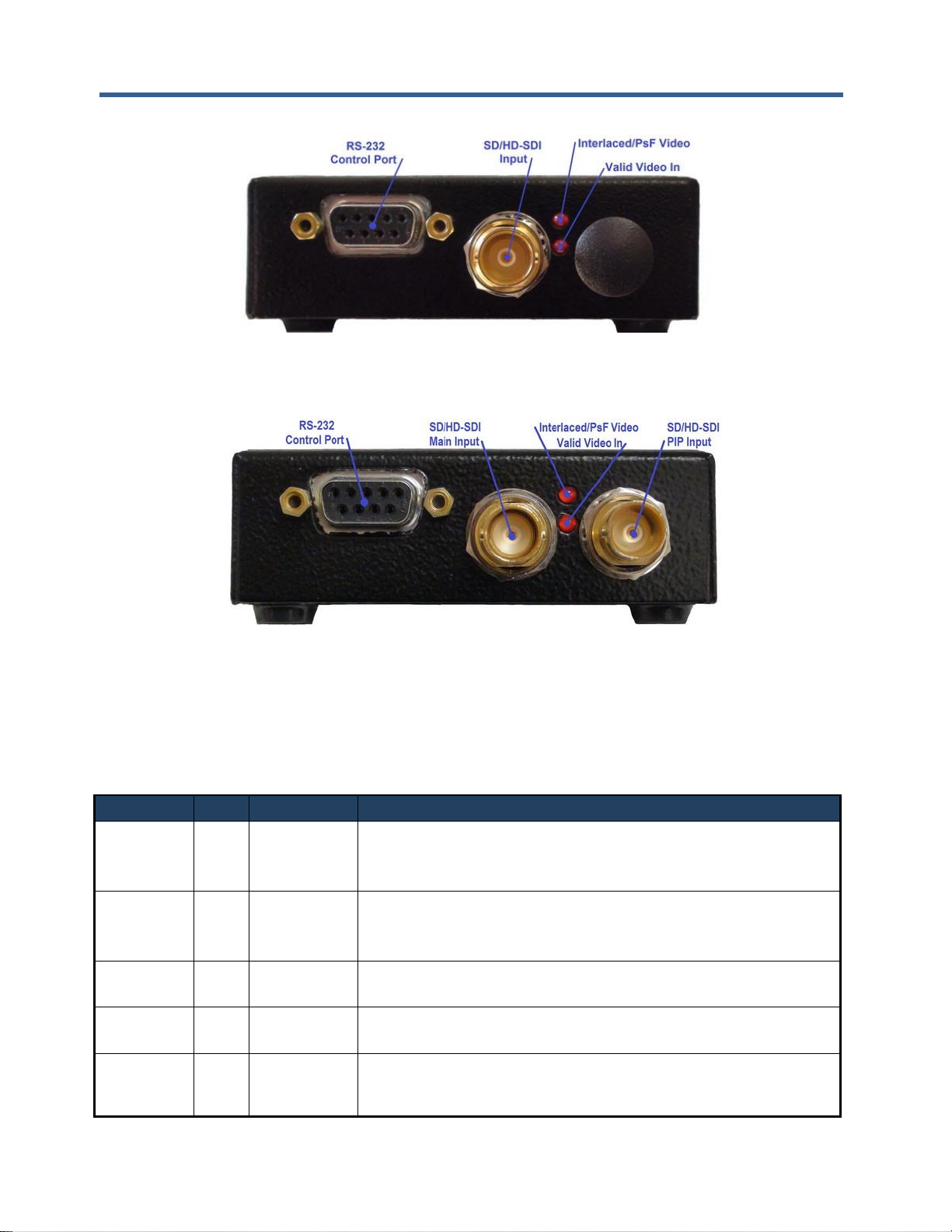
Figure 7: SDI Input & Status LEDs 17
Figure 8: SDI Inputs & Status LEDs (PIP product model) 17
Figure 9: DX-2200-TI Layer Order 19
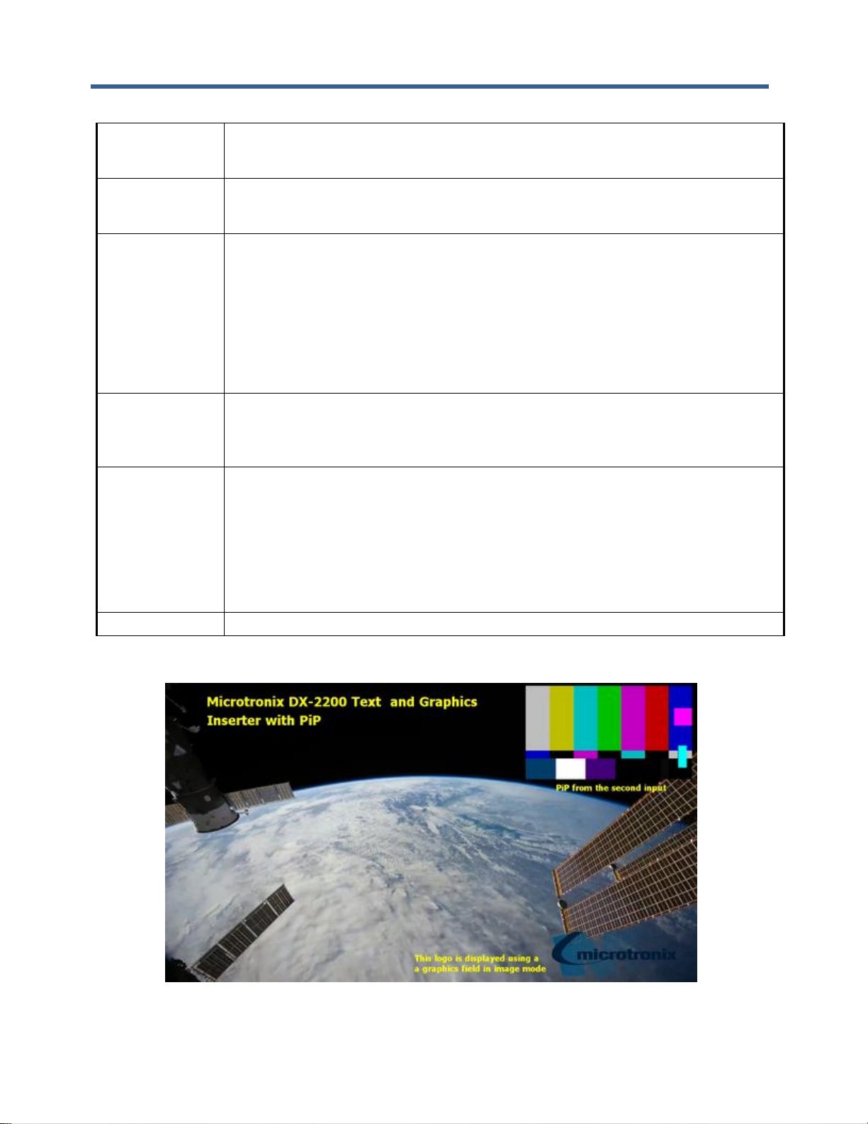
Figure 10: Sample of PiP, text and graphic logo OSD 24
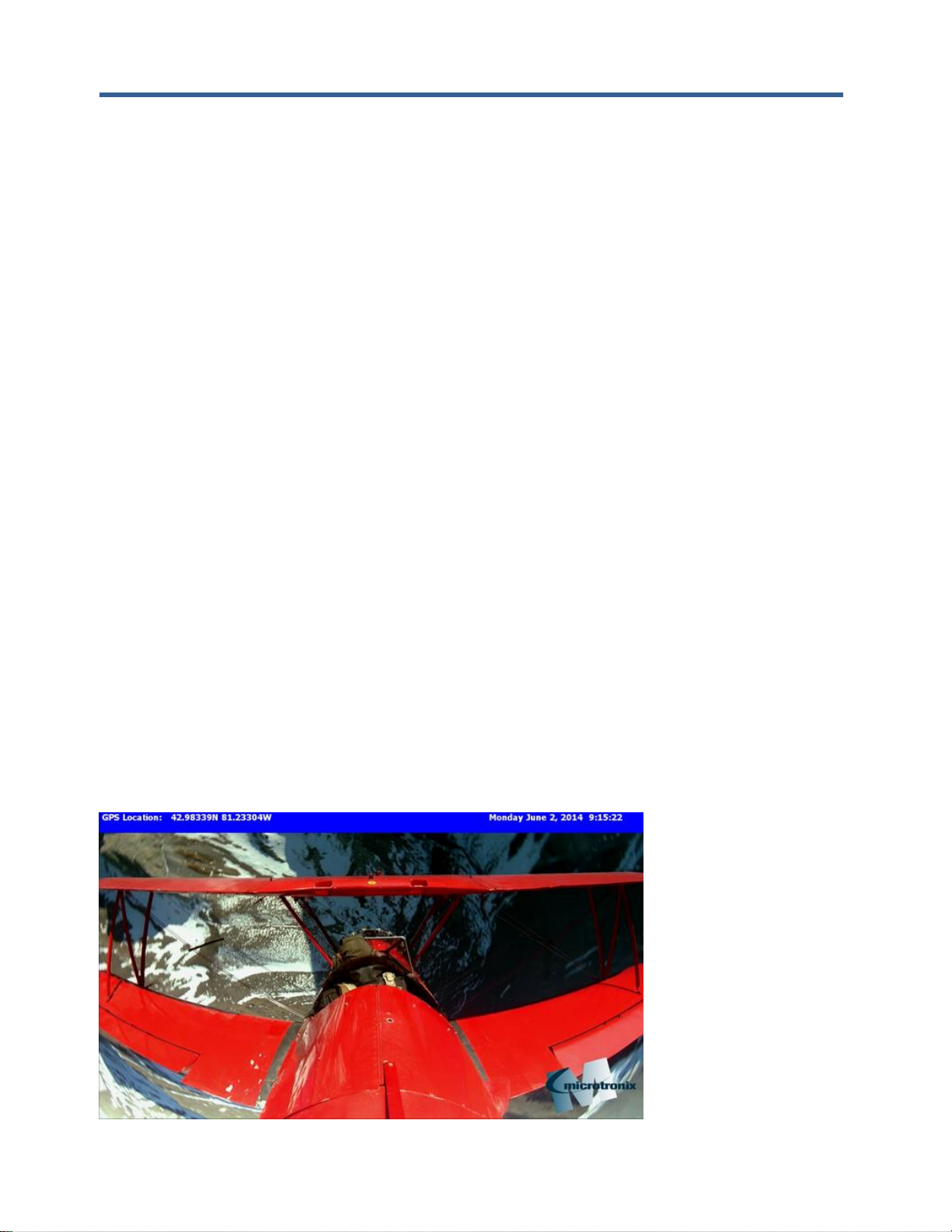
Figure 11: Sample of active text and graphic logo 29
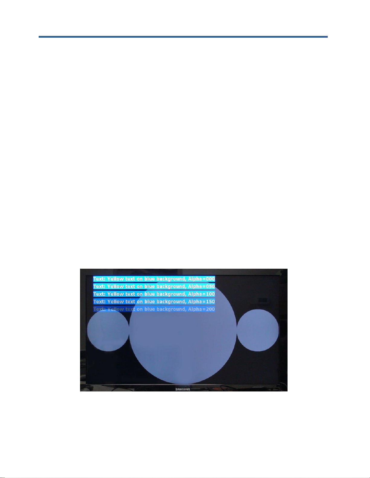
Figure 12: Sample of transparent text and background 30
Figure 13: Sample of the available Tahoma font sizes 32
Figure 14: Character set - codes 20-7F and A0-FF 33
Figure 15: Sample of Rectangle, Target Marker and Text 37
Figure 16: Sample of Corner Markers, Target and Text 38
Figure 17: Example 1 – red text OSD with white background 46
Figure 18: Example 2 – sample of default text 47
Figure 19: Frame Counter text display – Example 2 55
Figure 20: Frame Counter text display – Example 3 55
Figure 21: DB9 Serial Y Splitter Cable (Part # W6001) 65
Figure 22: Connection of Garmin GPS18xLVC 66
Figure 23: Example of GPS Data Display 76
Figure 24: Example of Frame Counter Time Clock Set by the GPS 77
Figure 25: DX-2200-TI – HD-SDI Text & Graphics Inserter Board 88
Figure 26: JTAG Cable Connection 90
Figure 27: DX-2200 Board (PN: P4115-TI-24) Mechanical Drawing 91
Figure 28: USB to DB9 RS-232 Serial Port Adapter Kit 93
Figure 29: PuTTY Session User Settings 95
Figure 30: PuTTY Terminal Settings 95
Figure 31: PuTTY Serial Port Settings 96
Page 10

DX-2200 – SD/HD-SDI Text & Graphics Inserter – User Manual
Page 10 of 103
1 Key Product Features
The key hardware features of the base DX-2200 – SD/HD-SDI Text & Graphics Inserter with Loop Output
(Model PN: DX-2200-TI-14) product includes:
• One 75Ω SD/HD-SDI input port
• Two 75Ω SD/HD-SDI output ports
• One for overlay output
• One for loop-though output
• One DB9 RS-232 Serial Control Port
The DX-2200 – Text & Graphic Inserter with PIP & Loop Output, (Model PN: DX-2200-TI-24) product
variant has an additional 75Ω SD/HD-SDI input port.
1.1 Supported Functionality
• Video Input formats:
o NTSC @ 29.97 fps (frames per second)
o PAL @ 25 fps
o 720p @ 25 / 29.97 / 30 / 50 / 59.94 / 60 fps
o 1080i @ 25 / 29.97 / 30 fps
o 1080p @ 23.98 / 24 / 25 / 29.97 / 30 fps
o 1080psf @ 23.98 / 24 / 25 / 29.97 / 30 fps
• Video Output automatically adjusts to match the input video format
• Ancillary data from the video input is preserved to provide pass-through of audio, closed captions and
other metadata on the main SDI input
• Text and Graphics Overlay OSD:
• Three overlay layers
• Up to 48 independent text or graphic Fields per layer
• Fields support text, rectangle, corner markers, target marker, and graphic images.
• Filled or open rectangles
• Size, color, transparency and position control
• Configurable background color for text
• Alpha blended text and background
• Alpha blending of graphic components
• Frame Counter text overlay display
• Three modes of operation:
o Mode 1 = Text Inserter,
o Mode 2 = Text Inserter with PiP using SDI Input 2 as PiP source*,
o Mode 3 = Text Inserter with Scaling
• Output video clock frequency locked to input
• Low video frame delay
• User defined operation of DIP & Toggle switches
• Flash storage of user configuration and text fields for auto system recovery after power-off
• 2MB of flash for storage of graphic images
• Firmware update over RS232 Serial Port
Page 11

DX-2200 – SD/HD-SDI Text & Graphics Inserter – User Manual
Page 11 of 103
1.2 Product Package Contents
The SD/HD-SDI Text & Graphics Inserter product package includes the following items:
• SD/HD-SDI Text & Graphics Inserter with Loop Output, Model PN: DX-2200-TI-14, or
• SD/HD-SDI Text & Graphics Inserter with PIP and Loop Output, Model PN: DX-2200-TI-24,
• 100-240VAC – 12VDC, 1.3A Power Adapter, PN: 589-PS-1213AP,
• USB 2.0 to RS-232 DB9 Serial Adapter Kit, PN: 8121-USB-RS232-KIT,
• User Manual on CD
Page 12

DX-2200 – SD/HD-SDI Text & Graphics Inserter – User Manual
Page 12 of 103
2 Introduction
The Microtronix DX-2200 – SD/HD-SDI Text & Graphics Inserter is a high performance single input video
text and graphics inserter supporting alpha blended text and graphics overlay / on screen display (OSD) on
progressive, psf and interlaced SD and HD video formats. With support for embedded audio, VBI content
and metadata, it is designed for use in broadcast, professional video recording studios, high-end
surveillance applications and Point-of-Sale security systems requiring live insertion of high quality text
streams onto a SDI video signal.
The unit auto detects the format of the input video and outputs in the same format. Custom user
configurations and parameters can be stored in on-board flash for auto restoration during power ON/OFF
cycles. A fail-safe buffered SD/HD-SDI Loop Output is available for passing through the input signal
unmodified as may be required for broadcast applications.
2.1 Text and Graphics Overlay OSD Features
Features of the overlay OSD include:
1) Three layers for text and graphics fields
2) Display of 48 independent fields per layer
3) Fields support Text, Rectangles, Corner Markers, Target Marker and Image modes
4) Text Field of up to 195 characters
5) Alpha blending of the text for smooth edges
6) Frame Counter on the top overlay layer
7) Independent color selection of fields
8) Configurable background color of text fields
9) Transparency control
10) Independent ON/OFF control of fields
11) X-Y position control
12) Permanent retention of text fields in flash memory
13) PIP of auxiliary SD/HD-SDI input (product variant option)
The text and graphics are supplied to the DX-2200-TI through the RS-232 serial port. The user can
optionally store the text fields in the on-board flash in which case they will be retained power ON/OFF power
cycles.
Page 13

DX-2200 – SD/HD-SDI Text & Graphics Inserter – User Manual
Page 13 of 103
3 Hardware
The SD/HD-SDI Text & Graphics Inserter is available as a stand-alone product supplied in an enclosure as
show in Figure 1 and Figure 2 below, or optionally as an open-frame board (for building into embedded
video system) as shown in Figure 25 shown in Appendix A.
Figure 1: DX-2200-TI-14 – SD/HD-SDI Text & Graphics Inserter with SDI Loop Output
Figure 2: DX-2200-TI-24 – SD/HD-SDI Text & Graphics Inserter with PIP and SDI Loop Output
Page 14
DX-2200 – SD/HD-SDI Text & Graphics Inserter – User Manual
Page 14 of 103
3.1 Power Requirements
The DX-2200-TI product is powered from either a 5 – 12Vdc 10W (100-240VAC 50/60Hz) regulated
switching power adapter with a 2-pin circular plug (female) connector (Switchcraft PN: 16282-2SG-311), or
optionally from a 14.4V Lithium ion brick battery.
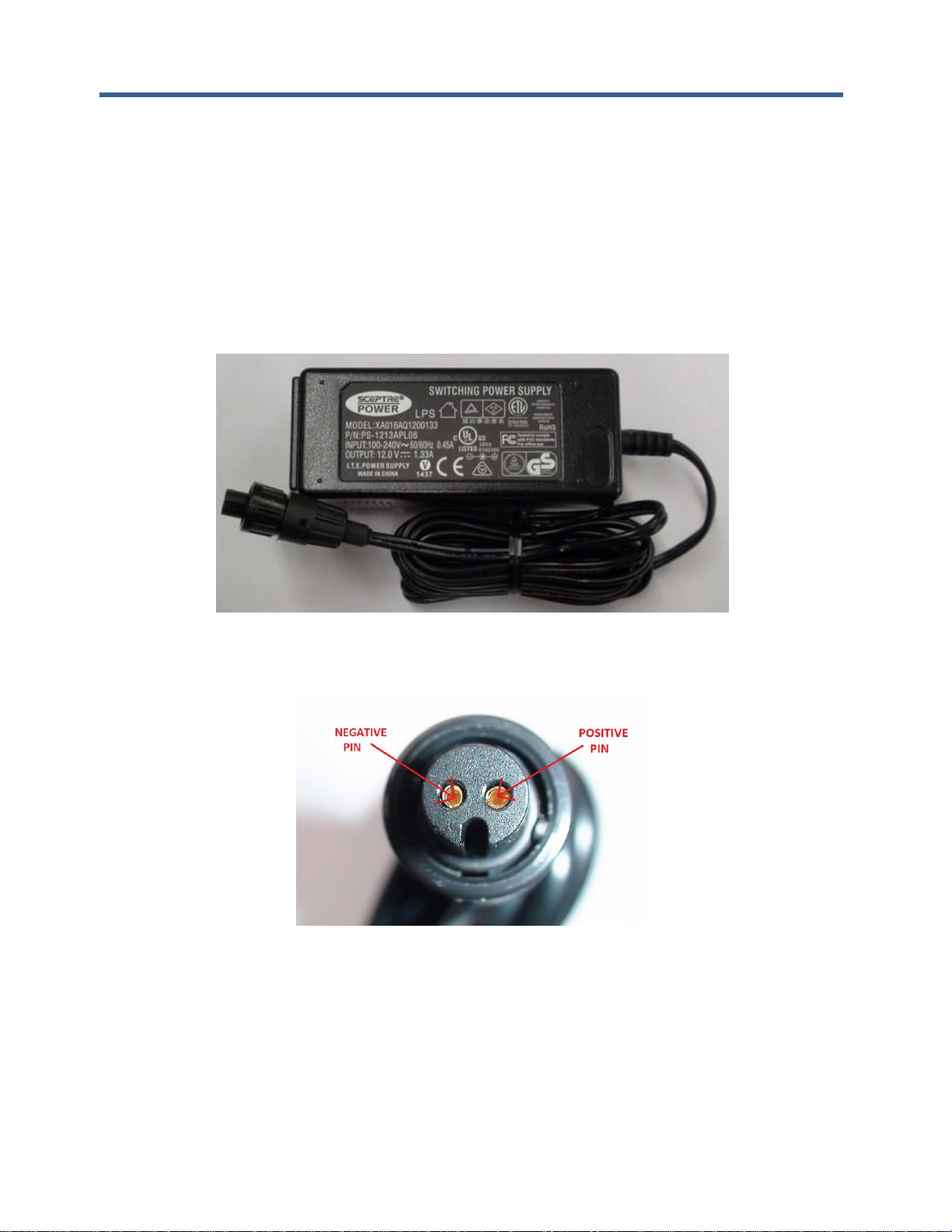
3.1.1 AC Power Adapter
The DX-2200-TI unit has a current draw of 650mA when operating from at 12VDC regulated power source.
A picture of the AC power adapter is shown in the figure below.
Figure 3: 12Vdc 1.33A 100-240VAC Power Adapter
Figure 4: Pin Assignments of 2-pin Power Plug
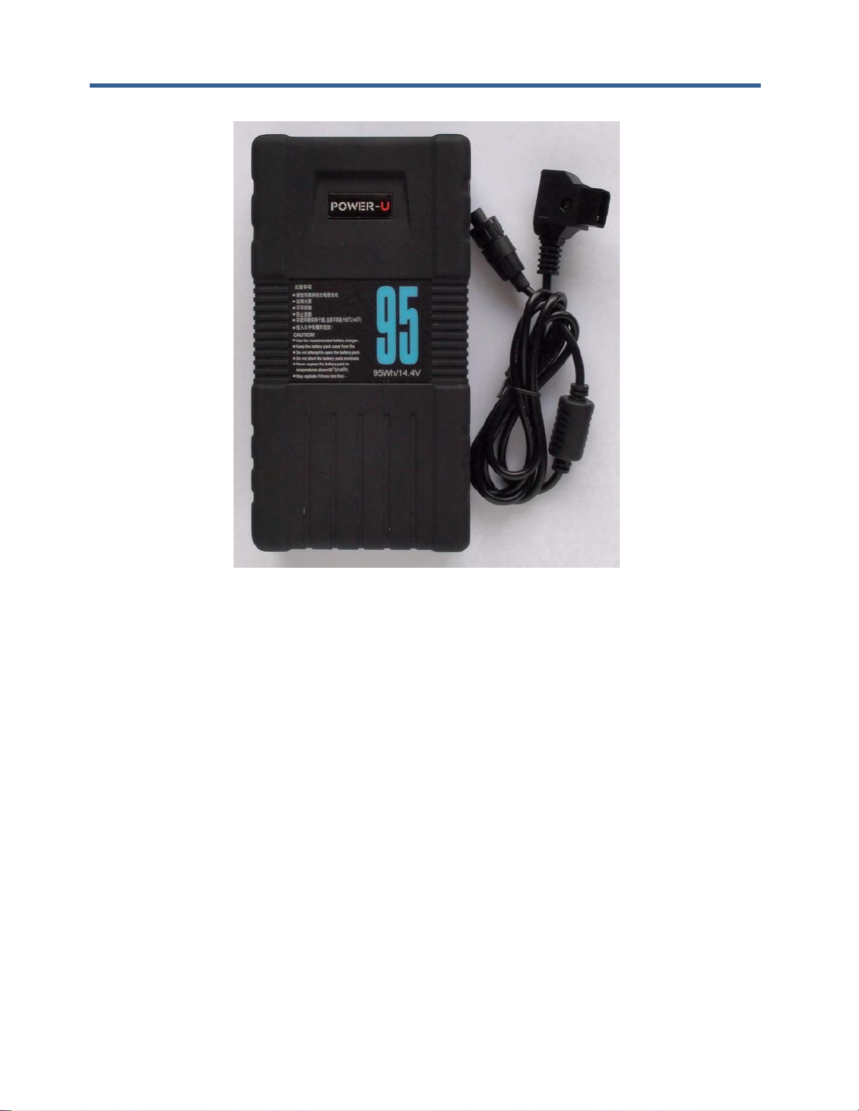
3.1.2 Example of 14.4VDC Lithium Battery
A picture of a 14.4VDC the AC power adapter is shown in the figure below.
Page 15
DX-2200 – SD/HD-SDI Text & Graphics Inserter – User Manual
Page 15 of 103
Figure 5: 14.4VDC Lithium Batter and D-TAP Cable
Microtronix does not sell Lithium Ion batteries. The 14.4VDC D-TAP adapter cable (shown in the figure
above) can be ordered using Microtronix part number D-TAP-2P-C.
3.2 Environmental Operating Limits
The DX-2200 unit uses passive convection cooling based on unrestricted airflow around the unit. The
environmental operating limits are as follows:
Ambient Temperature Range: 0C to 40C
Relative Humidity: 0 to 95% non-condensing.
Page 16
DX-2200 – SD/HD-SDI Text & Graphics Inserter – User Manual
Page 16 of 103
4 Operation
4.1 Default Startup Configuration
The factory default configuration for the DX-2200-TI has no saved configuration in flash and the following
DIP switch settings:
Table 1: Default DIP Switch Settings
DIP Switch
Setting
1
Off 2 Off 3 Off 4 Off
When powered up in the factory default configuration, the unit will pass the input video through to the output
with no text overlay items added. The DX-2200-TI will automatically output in the same video format as is
detected at the input.
If there is no input signal (or if it cannot be properly detected), the SDI output will display black and the video
format will be 720p @ 60 fps.
A user specific setup can be stored in flash to enable the DX-2200-TI to start in a different configuration, for
example with a text overlay displayed.
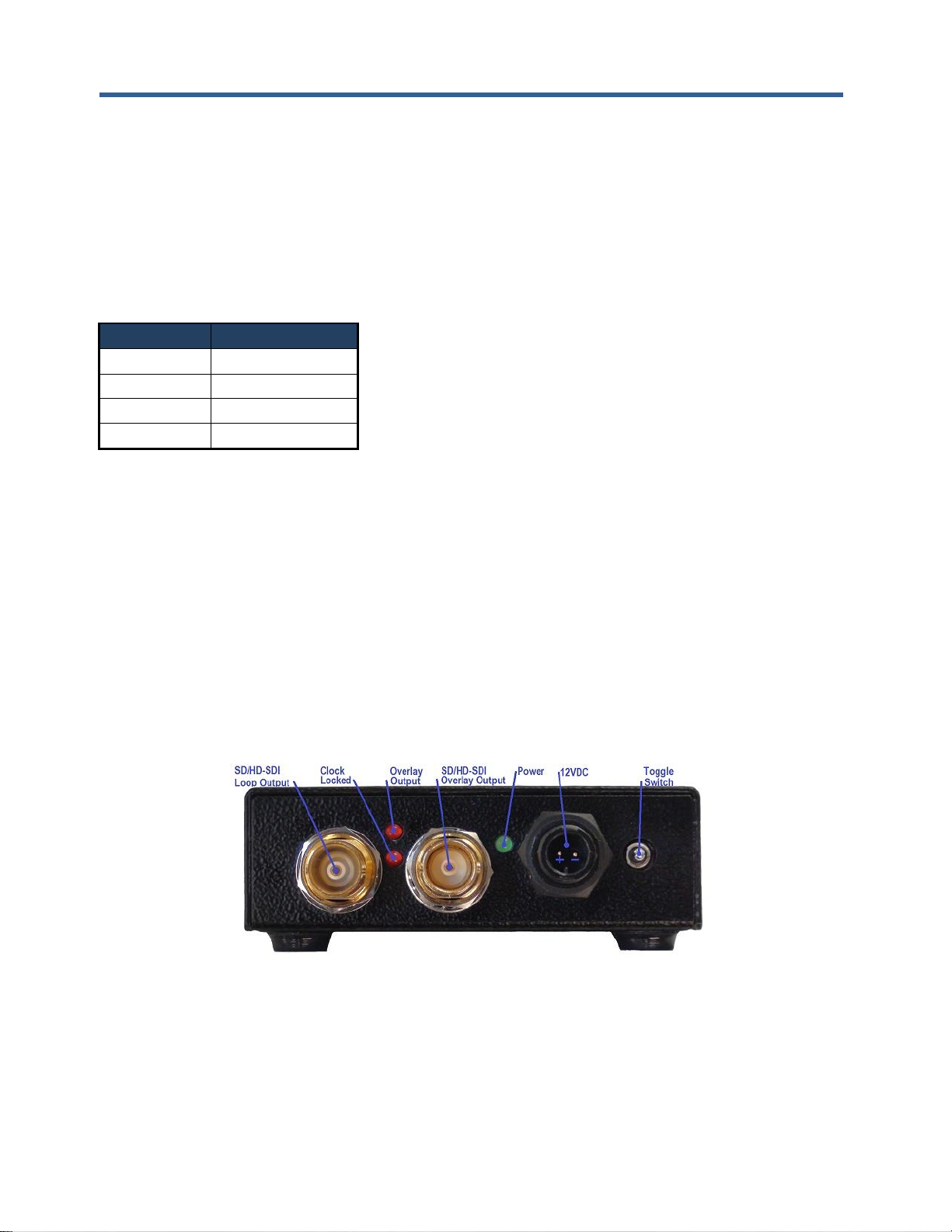
4.2 LED Status Indicators
The location of the 5 LEDs is show in the following figures.
Figure 6: SDI Outputs & Status LEDs
Page 17
DX-2200 – SD/HD-SDI Text & Graphics Inserter – User Manual
Page 17 of 103
Figure 7: SDI Input & Status LEDs
Figure 8: SDI Inputs & Status LEDs (PIP product model)
The operation of the status LEDs is summarized in Table 2 below.
Table 2: Description of LED Status Indicators
LED
Color
Use
Mode of Operation
Input-Top
(Board D4)
Red
Interlaced /
PsF Video
Detected
OFF: The SDI input video is a progressive video format.
ON: The SDI input video is either an interlaced or PsF video
format.
Input-
Bottom
(Board D4)
Red
Valid
Video
OFF: The SDI input has either no video, or an unsupported video
format.
ON: A signal is detected on the input.
Output
(Board D4)
Green
Power
ON: Power OK
Output-Top
(Board D5)
Red
Output On
OFF: SDI output is not enabled.
ON: The SDI output is enabled.
OutputBottom
(Board D5)
Red
Clock
Frequency
Lock
OFF: The output video clock is free running.
ON: The output video clock is frequency locked to the input video
clock.
Page 18

DX-2200 – SD/HD-SDI Text & Graphics Inserter – User Manual
Page 18 of 103
4.3 Video Format
The default video format is 720p @ 60 fps. If no input signal is connected at power-up (when operating in the
factory default configuration) the DX-2200-TI will output a black screen. The Text Overlay can be used
without input video connected.
When an SDI input with one of the supported video formats is connected, the unit will detect the video format
and switch the output to the match the detected video and attempt to lock to the clock frequency of the video
input. The video output will momentarily switch off as the video output is adjusted to match the format and
clock frequency of the input. When the clock frequency is locked, the video path is enabled and the input
video and ancillary data will appear at the output.
If the SDI input is disconnected, the unit continues to output in the last video format that was detected.
The default output video format can be changed by saving the configuration when the unit is operating with
the desired output format.
4.4 Picture-in-Picture (PiP)
Units equipped with the optional second SDI input connector (Input 2) are capable of PiP display using the
second SDI Input as the PiP source. The PiP video source can be asynchronous to the main video input or
can be a different resolution / frame rate. If the main input is an interlaced format, the PiP input must be
interlaced, and if the main input is a progressive format, the PiP input must be progressive. The size and
position of the PiP is programmable by software commands.
The PiP input will only function after the background video has been connected to Input 1. The PiP input
does not support audio or other ancillary data types. For interlaced formats, connection of a signal to the PiP
input may create an output video glitch as the unit synchronizes to the input.
4.5 Video Buffering and Frame Delay
For Text Inserter Mode (Mode 1) and Text Inserter with PiP (Mode 2), the DX-2200-TI includes a frame
buffer with a delay of 1 frame. The main video path has an additional delay of approximately 2000 clocks
(about 1 line in 1920x1080 video resolutions). The optional PiP video path has an additional delay that may
vary from 0 to 1 frame due to its support for asynchronous video inputs.
For Text Inserter with Scaling Mode (Mode 3), the DX-2200-TI has 2 frames of delay plus an additional delay
of approximately 4 lines.
4.6 Audio and Ancillary Data
The DX-2200-TI preserves ancillary data in the main SDI Input (Input 1) and passes it through to the output
to provide pass-through of audio, closed captions, and other ancillary data types embedded in the SDI video.
The optional PiP SDI Input (Input 2) does not support audio or other ancillary data types.
4.7 OSD Layers
The DX-2200-TI supports three video layers that are mixed on top of the SDI video input(s).
Page 19
DX-2200 – SD/HD-SDI Text & Graphics Inserter – User Manual
Page 19 of 103
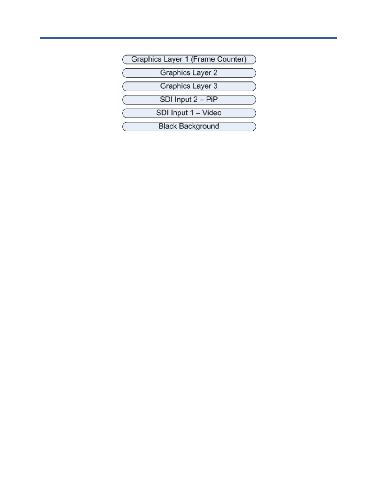
Figure 9: DX-2200-TI Layer Order
The top layer in the mix is referred to as Graphics Text Layer 1. This layer displays up to 48 Fields that
support text and graphics. The optional Frame Counter displays on this layer. Text Fields on this layer are
configured using either the Text Overlay Serial Commands or the Graphics Overlay Serial Commands. The
Frame Counter is configured by the Frame Counter Serial Commands.
The next two layers are Graphics Layer 2 and Graphics Layer 3. These layers each display up to 48 display
Graphic Fields that are controlled by the Graphic Overlay Serial Commands.
The 4th layer is the SDI video, and the 5th layer is the Black Background.
Within any one layer, no mixing of fields takes place. If two fields have pixels that occupy the same
coordinates, one will overwrite the other. When an update is performed to render the fields on a layer, the
fields are rendered in order of their field number. For example, Field 4 will always be rendered after Field 3
and will overwrite any pixels of Field 3 if they are in the same location in the frame.
When graphic fields on different layers are placed at the same coordinates, they mix according to their
transparencies and the layer order. When a field is fully visible, no content that is on the layers below it will
be visible. When the field is partly or fully transparent, it mixes with the layers below according to their
transparencies.
4.8 SERIAL & MANUAL Control
The SD/HD-SDI Video Text Inserter has two methods of control: SERIAL Control using the RS232 port, and
MANUAL Control using the DIP switch and Toggle switch. SERIAL Control allows control full of the
capabilities of the DX-2200-TI, and MANUAL Control provides a subset of functions.
SERIAL Control is always active. In the factory default configuration the Toggle Switch and DIP switch are
active.
The functions of the DIP switch and Toggle switch can be reconfigured by SERIAL Control commands to
customize the Switcher so that the controls provide the set of functions required for a specific user
application. The modified configuration can be saved on board in the flash configuration memory.
4.8.1 SERIAL Mode of Operation
When SERIAL control is used, the DX-2200-TI is controlled via commands sent to the DB9 Serial Control
Port.
The serial COM port of the computer connected to the DX-2200-TI should be configured for: 115,200 baud,
1 stop bit, and no flow control.
4.8.1.1 USB 2.0 to RS-232 Serial Port Adapter
The DX-2200 product is supplied with a USB 2.0 to DB9 RS-232 Serial Port Adapter Kit (PN: 811-USBRS232 Kit) to connect the DB9F Serial Port to a USB 2.0 port of a PC or laptop. The Kit consists of a USB
Page 20
DX-2200 – SD/HD-SDI Text & Graphics Inserter – User Manual
Page 20 of 103
2.0 to RS232 DB9 Serial Adapter Cable (StarTech PN: ICUSB232V2) and a 6 foot male to female DB9
RS232 serial cable. Refer to Appendix B for more information.
4.8.1.2 DX-2200 Serial Port Control Commands
In the SERIAL mode, commands sent to the Serial Control Port control the operation of the DX-2200-TI.
Commands consist of ASCII alpha-numeric codes and are not case sensitive. All Serial Commands are
terminated with a carriage return (CR), a line feed (LF), or a semicolon. The use of a semicolon terminator
allows more than 1 command per line to improve readability of script files.
Commands may be sent directly to the DX-2200-TI one character at a time using a terminal program running
on a connected computer, or they may be developed in a text editor such as Notepad and then uploaded to
the DX-2200-TI by the terminal program. The second method has the advantage of allowing the commands
to be saved, viewed, edited and resent. The text editor used must save the configuration files as 8 bit ASCII
data.
Space or tab characters before a command or trailing a command are ignored, as are spaces or tabs
following a comma that separates parameters within a command. Any characters on a line following a tick (')
character are treated as comments. A comment may begin after a delimiter, or may follow a command with
or without spaces or tabs between the command and the comment.
ASCII string parameters are delimited with quotation marks. If a quotation mark or backslash character is
required within a string (for example to display as part of a text overlay), then it must be preceded by a
backslash character.
Valid and invalid Serial Commands are acknowledged with a ‘+’ and ‘-’ response respectively. Carriage
return, line feed, or semicolon characters without a preceding command are acknowledged with a ‘*’.
The command codes are extensible, additional commands and functionality can be added as required.
Contact Microtronix sales or technical support with your requirements.
Table 3: Serial Port Command Acknowledgement Codes
Response Code
Mode of Operation
+
Valid command received
-
Invalid command received
*
Valid CR, LF, semicolon, or comment line received
4.8.1.3 Input Video Transparency SERIAL Command
The Input Video Transparency Commands set the transparency of the input 1 SDI video. By default the, the
SDI input video has no transparency. By using these commands, the input video can be made partially
transparent so that the black background layer becomes visible.
Table 4: Transparency SERIAL Command Codes
Command Code
Mode of Operation
An – Set transparency of the SDI input 1 video
A0
0% transparency
A1
12.5% transparency
A2
25% transparency
A3
37.5% transparency
Page 21
DX-2200 – SD/HD-SDI Text & Graphics Inserter – User Manual
Page 21 of 103
A4
50% transparency
A5
62.5% transparency
A6
75% transparency
A7
87.5% transparency
A8
100% transparency
Annn
Set the transparency with higher resolution where nnn – is a three digit
number between 000 and 255 where 000 is 0% transparent and 255 is
100% transparent
4.8.1.4 Mode Control SERIAL Command
The Mode Control SERIAL Command selects an operating mode for the product and are listed in Table 5
below.
Table 5: Mode Control SERIAL Command Codes
Command Code
Mode of Operation
M1
Text Inserter
M2
Text Inserter with PiP using Input 2 as the PiP source. PiP will only
activate if a valid video input is present at Input 2.
M3
Text Inserter with Scaling. Note that the video output is momentarily
interrupted when switching into or out of Mode 3.
4.8.1.5 Ancillary Data SERIAL Commands
By default, the DX-2200-TI preserves all ancillary data in the video signal. It is possible to control this
function if the ancillary data is not required. Disabling the ancillary data may slightly increase graphic update
speed in some situations.
Table 6: Ancillary Data Control SERIAL Command Codes
Command Code
Mode of Operation
MA0
Disable ancillary data pass through
MA1
Enable ancillary data pass through
4.8.1.6 Baud Rate SERIAL Command
The DX-2200-TI always powers up at 115200 baud. After power up, the baud rate can be changed using the
MBnnnnnnn command, where nnnnnnn is the new baud rate between 9600 and 1000000 baud.
The response to the baud rate command is transmitted before the baud rate is changed. It is recommended
to wait 100 ms after receiving the response before sending commands at the new baud rate to ensure the
DX-2200-TI is ready to receive commands at the new rate.
NOTE: The DX-2200-TI always starts at 115200 baud. Changes to the baud rate cannot be saved to flash.
Page 22

DX-2200 – SD/HD-SDI Text & Graphics Inserter – User Manual
Page 22 of 103
Table 7: Baud Rate SERIAL Command Codes
Command Code
Mode of Operation
MBnnnnnnn
Set the baud rate to nnnnnnnn where nnnnnnnn is a number
between 9600 and 1000000 baud.
4.8.1.7 Picture-in-Picture Position, Size, and Zoom SERIAL Commands
These commands apply only to the Text Inserter with PiP mode of operation (Mode 2, see the Mode Control
Serial Commands).
The position and size of the Picture-in-Picture (PiP) display is selected through character commands sent
via the RS-232 port per Table 6 below.
There are two different methods of controlling the PiP size and position. The first method selects one of four
predefined positions and one of 16 predefined sizes using the commands PSnn, PAxxxx, PByyyy, followed
by P3, P4, P5, P6, P7, or P8 to set the positions and apply the settings.
For example: PiP in the bottom right corner using control method 1:
PS04 ' Set PiP size to be 4/16ths of the video width
PA20 ' Offset PiP 20 pixels horizontally from edge of the video
PB20 ' Offset PiP 20 pixels vertically from the edge of the video
P2 ' Apply settings and place PiP in bottom right corner
If the PS, PA, or PB commands are omitted in the above example, the previous setting, or the default will
apply. The default size for the PiP window is 6/16th of the video width (equivalent to the command PS06).
The default horizontal and vertical offset is 1 pixel + 1% of the screen width. If the P2 command is omitted
there will be no visible change to the PiP because it is this command that applies the parameters set the
other commands in the example.
The second method of setting PiP size and position does not use predefined sizes or positions, instead the
width, height, and the x and y position of the top left corner are set in terms of number of pixels by using the
commands PWxxxx, PHyyyy, PXxxxx, PYyyyy, followed by either PU or PR to apply the settings.
For example: PiP configured using method 2:
PX100 ' Set Top Left corner of PiP to x=100 pixels from the left
PY400 ' Set Top Left corner of PiP to y=400 pixels from the top
PW711 ' PiP window width = 711 pixels
PH400 ' PiP window height = 400 pixels
PU ' Apply the PiP Settings
This control method allows the aspect ratio of the PiP window to be changed, possibly resulting in stretched
or compressed video in the PiP window. If the PR command is used instead of the PU command, the height
parameter set for the PiP window by the PH command is ignored, and a value is calculated from the width to
provide a 16:9 aspect ratio for the PiP window.
In all cases, the PiP window must fit within the video. It is not possible to place the PiP window partly or fully
off screen. The DX-2200 will automatically adjust the gap, position and size parameters as needed to force
the PiP window to fit on screen. The minimum PiP width and height is 32 pixels. The DX-2200 will
automatically adjust the size to prevent the PiP windows being smaller than this size.
The PiP supports a limited zoom / cropping function that allows a selected region of the PiP video source to
be overlaid on the main channel instead of the entire frame. Two modes for selecting a region of the frame
are provided. The first method is controlled by a zoom factor specified in percent and a center location for
the zoom. The second method selects the top and left edge of the region, and the width and height. These
Page 23

DX-2200 – SD/HD-SDI Text & Graphics Inserter – User Manual
Page 23 of 103
functions do not upscale the PiP input source. At most, each input pixel can generate 1 output pixel. The
DX-2200 automatically limits the values of the command parameters if the requested settings exceed the
valid ranges, for example by calling for magnification of the source.
Table 6: PiP Control Serial Command Codes
Command Code
Mode of Operation
P1
PiP upper right with preset size
P2
PiP lower right with preset size
P3
PiP upper left with preset size
P4
PiP lower left with preset size
P5
PiP top center with preset size
P6
PiP bottom center with preset size
P7
PiP center left with preset size
P8
Pip center right with preset size
PSnn
Set the PiP size used with the predefined PiP positions. The width is set in units of
16ths of the output video width. For example PS05 set the width to 5/16ths of the video
width.
PAxxxx
Set the horizontal gap in pixels between the reference corner and the Pip window when
using the predefined PiP positions. Enter the value 9999 to use the default.
PByyyy
Set the vertical gap in pixels between the reference corner and the Pip window when
using the predefined PiP positions. Enter the value 9999 to use the default.
PU
PiP update – sets PiP size and position to values selected with W, H, X and Y
commands
PR
PiP update, fixed aspect ratio – sets PiP size and position to values selected with PW,
PX and PY commands, and caluclates a height to mnake the PiP window have 16:9
aspect ratio
PWxxxx
PiP width where xxxx is the number of horizontal pixels
PHyyyy
PiP height where yyyy is the number of vertical pixels
PXxxxx
PiP horizontal position where xxxx is the number of pixels from the left side of the
screen.
PYyyyy
PiP vertical position where yyyy is the number of pixels from the top of the screen
AFn
Set the PiP transparency where n is a single digit in the range 0 to 8.
n = 0 - 0 % Transparent
n = 1 - 12.5 % Transparent
n = 2 - 25 % Transparent
n = 3 - 37.5 % Transparent
n = 4 - 50 % Transparent
n = 5 - 67.5 % Transparent
n = 6 - 75 % Transparent
n = 7 - 87.5 % Transparent
n = 8 - 100% Transparent
AFnnn
Set the PiP transparency where nnn is a three digit value in the range 000 (fully visible)
to 255 (fully transparent).
Page 24
DX-2200 – SD/HD-SDI Text & Graphics Inserter – User Manual
Page 24 of 103
ZPF
Set PiP zoom function to be controlled in percentages by specifying center position and
zoom factor. This is the default control mode. After setting this mode, use the ZPCX,
ZPCY and ZPnnn commands to control the zoom function.
ZPW
Set PiP zoom to be controlled in pixels by specifying left edge and top edge position,
and the width and height. After setting this mode, use the ZPLX, ZPLY, ZPLW, and
ZPLH commands to setup the PiP window.
ZPCXnnn.d
ZPCYnnn.d
Set the center of the PiP Zoom, where nnn.d is a number from 0 to 100 with up to 1
optional decimal place. This number represents a position in the PiP source to use as
the zoom center point, specified in percent of the video width (ZPCX) or height (ZPCY).
The resulting zoom window can never extend beyond the edge of the PiP video source.
The DX-2200 automatically restricts the values to a valid range.
The default setting is 50% for both horizontal and vertical, meaning the PiP is zoomed
in toward its center.
These commands only has an effect in center / zoom control mode. See the ZPF
command.
ZPnnn.d
Set the zoom factor as a percentage from 100.0% to 800.0% with up to one optional
decimal place. The default is 100% (no zoom).
This command only has an effect in the center / zoom control mode. See the ZPF
command.
ZPLXnnnn
ZPLYnnnn
ZPLWnnnn
ZPLHnnnn
Set the PiP zoom window left edge (ZPLX), top edge (ZPLY), width (ZPLW) or height
(ZPLH). Note: This command selects a region of the PiP input source to display, it does
not set the position of the PiP window in the output video.
For each command, nnnn represents the number of pixels.
The DX-2200 automatically restricts the values to a valid range. The PiP zoom window
cannot be less than 32x32 pixels, or extend beyond the edge of the PiP source.
These commands only have an effect when specifying PiP window coordinates in
pixels. See the ZPW command.
ZPR
Reset the PiP zoom / crop settings to the defaults
Figure 10: Sample of PiP, text and graphic logo OSD
Page 25

DX-2200 – SD/HD-SDI Text & Graphics Inserter – User Manual
Page 25 of 103
4.8.1.8 Main Input Scaling and Position SERIAL Commands
These commands apply only to the Text Inserter With Scaling mode of operation (Mode 3, see the Mode
Control Serial Commands).
The Text Inserter With Scaling Mode (Mode 3) provides the graphic overlay functions and two additional
capabilities:
1) The option to zoom in on a selected region of the video source to allow cropping or display of a
selected rectangular region of the source.
2) The video source can be mixed into the output as a reduced size window instead of filling the output
video frame. This function is controlled by the Output Window Size and Position SERIAL Command
Codes ("B" commands) shown in the table below
Page 26
DX-2200 – SD/HD-SDI Text & Graphics Inserter – User Manual
Page 26 of 103
Table 7: Output Window Size and Position SERIAL Command Codes
Command
Code
Mode of Operation
Mode Control Commands
BXnnnn
Set the left edge location of the output video window in either pixels, or in percentage of
the frame width by appending the '%' symbol.
The window must always fit within the video frame. The DX-2200 will limit the value
entered with this command to keep the window within the frame.
BYnnnn
Set the top edge location of the output video window window in either pixels, or in
percentage of the frame height by appending the '%' symbol.
The window must always fit within the video frame. The DX-2200 will limit the value
entered with this command to keep the window within the frame.
BWnnnn
Set the width of the video output window in either pixels, or percentage of the video
frame width by appending the '%' symbol. The value 9999 has a special meaning and
causes the width to be calculated automatically from the height to maintain the aspect
ratio.
The DX-2200 will always limit the window size to prevent it being larger than the video
frame.
BHnnnn
Set the height of the video output window in either pixels, or in percentage of the video
frame height by appending the '%' symbol. The value 9999 has a special meaning and
causes the height to be calculated automatically from the width to maintain the aspect
ratio.
The DX-2200 will always limit the window size to prevent it being larger than the video
frame.
BR
Reset size and position to defaults
Where ‘nnnn’ can be a number of pixels between one and four digits in length, or be followed by a ‘%’
sign to specify a percentage of the output frame size, eg ‘50%’. When specified in %, the value can be
an integer between 0 to 100.
Table 8: Text Inserter with Scaling Zoom SERIAL Command Codes
Command
Code
Mode of Operation
Mode Control Commands
ZSF
Set the zoom function to be controlled in percentages by specifying center position and
zoom factor. This is the default control mode. After setting this mode, use the ZSCX,
ZSCY and ZPnnn commands to control the zoom function.
ZSW
Set the zoom to be controlled in pixels by specifying left edge and top edge position,
and the width and height. After setting this mode, use the ZSLX, ZSLY, ZSLW, and
ZSLH commands to setup the PiP window.
ZSCXnnn.d
ZSCYnnn.d
Set the center location of the Zoom, where nnn.d is a number from 0 to 100 with up to 1
optional decimal place. This number represents a position in the video source to use as
the zoom center point, specified in percent of the video width (ZSCX) or height (ZSCY).
The resulting zoom window can never extend beyond the edge of the video source. The
DX-2200 automatically restricts the values to a valid range.
The default setting is 50% for both horizontal and vertical, meaning the video is zoomed
in toward its center.
These commands only has an effect in center / zoom control mode. See the ZSF
command.
Page 27

DX-2200 – SD/HD-SDI Text & Graphics Inserter – User Manual
Page 27 of 103
ZSnnn.d
Set the zoom factor as a percentage from 100.0% to 800.0% with up to one optional
decimal place. The default is 100% (no zoom).
This command only has an effect in the center / zoom control mode. See the ZSF
command.
ZSLXnnnn
ZSLYnnnn
ZSLWnnnn
ZSLHnnnn
Set the zoom window left edge (ZSLX), top edge (ZSLY), width (ZSLW) or height
(ZSLH). Note: This command selects a region of the input source to display, it does not
set the position of the window in the output video.
For each command, nnnn represents the number of pixels.
The DX-2200 automatically restricts the values to a valid range. The zoom window
cannot be less than 32x32 pixels, or extend beyond the edge of the source.
These commands only have an effect when specifying the zoom window coordinates in
pixels. See the ZSW command.
ZSR
Reset the zoom settings to the defaults
4.8.1.9 Graphic Overlay SERIAL Commands
The Graphic Overlay Serial Commands support three layers that can each display up to 48 user-defined
Graphic Fields. Each Graphic Field can be configured to be Text, Rectangle, Corner Marker, or Target
Marker. The fields can be configured and positioned using the Graphic Overlay Serial Commands below.
Each Layer of the Graphic Overlay utilizes two frame buffers located in memory. One is these frame buffers
(the active buffer) generates a video output that is mixed on top of the input video, while the other buffer (the
spare buffer) is prepared for use.
The video output of the layer is updated by rendering all Graphic Fields into the spare buffer using the
parameters that have been set for each Field. The amount of time required to render the text to the spare
buffer depends on the number of pixels that must be drawn. Typically, the rendering process takes more
than one frame to complete. During this time, the active buffer continues to provide the Graphic Overlay
video output. After rendering is complete, the DX-2200-TI switches the active and spare buffers. The buffer
that was active before the update becomes the new spare buffer and is cleared by the unit to so that it is
ready for text to be rendered again when the next update occurs. Buffer switching is always performed at the
end of frame.
Many of the Graphic Field commands update the parameters of a Field (for example the visibility, color or
transparency), but do not update the video output. This allows the user to change as many parameters as
required before sending a command to show the updated output.
4.8.1.9.1 ACTIVE LAYER
The Graphics Overlay of the DX-2200-TI-03 has three layers named Graphics Layer 1, Graphics Layer 2
and Graphics Layer 3. The Graphic Overlay Commands do not include the layer number in the command
syntax. Instead, the commands always operate on the Active Layer. To select the Active Layer, the GLn
command is used where n is the layer number from 1 to 3. The default Active Layer is Graphics Layer 2.
Additionally, Graphics Layer 1 can also be accessed by the 'S' commands (See Graphic Layer 1 Overlay
SERIAL Commands). These commands always refer to Graphic Layer 1 regardless of the Active Layer.
4.8.1.9.2 GRAPHIC FIELDS
Graphic Fields are numbered 1 through 48. The Graphic Overlay Commands that apply to a single field
include the field number in the command, for example, the GnnS command enables display of field
number nn.
For any command that uses a field number, the field can be specified as either a 1 or 2 digit number in the
range 1 through 48.
Page 28

DX-2200 – SD/HD-SDI Text & Graphics Inserter – User Manual
Page 28 of 103
Instead of specifying a single field, the commands can be applied to all fields on the layer by specifying a
field number of 0. For example G0S enables the display all fields on the layer and is equivalent to the
commands G1S, G2S, G3S… G48S.
Commands can be applied to a range of sequential fields using the syntax "f1-f2" for the field number where
f1 is the first field and f2 is the last field the command applies to. For example the command G7-10S enables
display of fields 7, 8, 9, and 10.
By default, all Graphic Fields are turned off and have default parameters. To display a field, the following
steps are required:
1) the field must be configured with the required field type
2) the parameters must be set appropriately
3) display of the field must be enabled
4) the layer must be updated
Some commands combine the last two operations in the above list, for example the G2S command enables
the display of Graphic Field 2 (on the active layer) and also updates the layer.
The following commands are a simple example that displays a rectangle. These commands are intended for
use with the DX-2200-TI in the factory default configuration:
G1M2 ‘ Set Field 1 to be a Rectangle Field
G1PA100,100 ‘ Coordinate A = (100,100)
G1PB300,300 ‘ Coordinate B = (300,300)
G1S ‘ Enable display of Field 1 and update the layer
4.8.1.9.3 RESET GRAPHIC FIELD
A Graphic Field can be reset to its default values with the GnnZ command where nn is the Graphic Field
number to reset. The GZ command will reset all Graphic Fields on the Active Layer, and the G0Z command
resets the fields on all layers to default.
Resetting a Graphic Field will clear the Text string, set the line color to white with full visibility, set the
position to the top left corner, set the fill color to blue but fully transparent (not visible), and set the font to the
default for the current video resolution. The overall visibility of the Field is set to off.
Resetting fields does not automatically update the video output of the overlay. Any fields that are visible in
the video are not cleared until a command is received that causes the overlay to be updated.
4.8.1.9.4 GRAPHIC FIELD VISIBILITY
Each Graphic Field can be turned on or off independently. By default, fields are off. The GnnV, GnnS, and
GnnH commands control the visibility of field number nn. GnnS and GnnH turn visibility on and off
respectively, and GnnV toggles visibility between on and off. Using any one of these commands will also
cause the video output to be updated by rendering the fields to the spare buffer and performing a buffer
swap. For this reason, it may be undesirable to use these commands when several text fields need to be
turned on or off because the video output will be updated as each command is executed. This will result in
the fields turning on or off one at a time.
The commands GnnVN, GnnSN, and GnnHN also control the visibility of Graphic Field nn, but without
updating the output and are recommended when the visibility of more than one field is to be changed at the
same time. The GU command can be sent to update the output after all visibility changes have been made.
The GnnHdddd command will turn off the visibility of text field nn after approximately dddd frames of video
have been output. When the GnnH is used with a delay, the overlay is automatically updated after the delay.
Page 29
DX-2200 – SD/HD-SDI Text & Graphics Inserter – User Manual
Page 29 of 103
4.8.1.9.5 UPDATE GRAPHIC OVERLAY
The GU command updates the video output of the Overlay by rendering all fields to the spare buffer and
exchanging the active and spare buffers.
After sending a sequence of commands that change the parameters of fields, send the GU command to
make the changes visible.
4.8.1.9.6 COORDINATE SYSTEM AND FIELD POSITION
Each Graphic Field has two position coordinates referred to as Coordinate A and Coordinate B. One or both
of these coordinates may be used depending on the Graphic Field Type.
The coordinate system designates x=0000 and y=0000 as the top-left corner of the overlay for all video
formats. This is the default position for all fields.
The maximum value for the x and y coordinates is located at the bottom-right corner of the frame. For
1080p, 1080i, and 1080PsF formats the bottom-right corner is at coordinates x=1919, y=1079. For 720p
formats the bottom-right corner is located at x=1279, y=719. For NTSC format the coordinates are x=719,
y=485, and for PAL format x=719 and y=575.
NOTE: Some monitors will not display the entire video frame, particularly when operating in NTSC or PAL
modes. Graphic Fields placed close to the edges of the overlay may not be visible on some monitors.
NOTE: If the Overlay has been re-sized, the coordinate range may be smaller than the defaults for each
video mode listed above.
Any Field or portion of a Field that extends beyond the edges of the Overlay will not be visible.
The command set provides different options for setting the coordinates of a Graphic Field. The commands
GnnXxxxx, and GnnYyyyy set the x and y position for Coordinate A individually. The commands
GnnPAXxxxx and GnnPAYyyyy perform the same functions, but this form of the command can also set
Coordinate B, for example GnnPBXxxxx or GnnPBYyyyy.
If it also possible to set both x and y in a single command for Coordinate A or Coordinate B with the
commands GnnPAxxxx,yyyy and GnnPBxxxx,yyyy respectively. For all Graphic Field position commands,
the parameters xxxx and yyyy can be from 1 to 4 digits in length and may optionally be prefixed with zeros.
For example, sending G4X0200 and G4Y0400 sets the field position to (200, 400).
Changing the text position does not automatically update the video output.
Figure 11: Sample of active text and graphic logo
Page 30
DX-2200 – SD/HD-SDI Text & Graphics Inserter – User Manual
Page 30 of 103
4.8.1.9.7 LINE COLOR AND TRANSPARENCY
Each Graphic Field has a Line Color specified by Red, Green, and Blue Components in the range from 0 to
255. The Line Color is used for solid rectangles, for the outline of open rectangles, for corner markers, target
markers, and the foreground of text.
The colors are entered as three Serial Commands by sending a Red, Green and Blue Serial Command. For
example: sending G1R220, G1G025 and G1B250 sets Text Field 1 to purple.
The default color is white (R255, G255, and B255). Changing the text color does not automatically update
the video output.
The Line Color has a transparency property that can be controlled using the G1Aaaa command to set the
alpha value for mixing with underlying layers. Setting the alpha value to 0 sets the Line Color to be fully
visible and no content on lower video layers will be visible through the Line Color. An alpha of 255 sets the
Line Color fully transparent. At this setting the color will be completely invisible.
For example: sending G1A192 makes Field 1 approximately 75% transparent. Changing the text
transparency does not automatically update the video output.
4.8.1.9.8 BACKGROUND COLOR AND TRANSPARENCY
Each Field has a Background Color that is used for the background of Text Fields and the fill color of
rectangles. Background Color is set in the same way as Line Color, except the commands used as
GnnBRrrr, GnnBGggg, GnnBBbbb, and GnnBAaaa.
The following example commands set the Background Color of Graphic Field 1 to yellow with partial (50%)
visibility: G1BR255, G1BG255, G1BB0, and G1BA128.
The Background Color will only affect those field types that make use of the Background Color.
Figure 12: Sample of transparent text and background
NOTES: When the text is partially transparent, its apparent color will be determined by the text color,
the background color and the visibilities of the text and background.
When a text background is displayed, the total number of color / transparency combinations is limited. Small
changes in the color or transparency parameters of the text or background may not change the appearance
Page 31

DX-2200 – SD/HD-SDI Text & Graphics Inserter – User Manual
Page 31 of 103
4.8.1.9.9 TEXT FONT
For each Graphic Field, a font / size combination can be selected using the GnnFfff command to select one
of the font options in the Text and Symbol Font Table.
Table 9: Text and Symbol Fonts
Font Code
Font Name
Height
Pixels
Fixed
Width
Code Range
(Hexadecimal)
12
Tahoma Bold
18
20-7E & A0-FF
1
Tahoma Bold
26
20-7E & A0-FF
13
Tahoma Bold
32
20-7E & A0-FF
2
Tahoma Bold
40
20-7E & A0-FF
25
Tahoma Bold
48
20-7E & A0-FF
14
Tahoma Bold
60
20-7E & A0-FF
3
Tahoma Bold
78
20-7E & A0-FF
15
Tahoma Bold
116
20-7E & A0-FF
4
Tahoma Bold
156
20-7E & A0-FF
16
Tahoma Regular
18
20-7E & A0-FF
17
Tahoma Regular
26
20-7E & A0-FF
18
Tahoma Regular
32
20-7E & A0-FF
19
Tahoma Regular
40
20-7E & A0-FF
24
Tahoma Bold
48
20-7E & A0-FF
20
Tahoma Regular
60
20-7E & A0-FF
21
Tahoma Regular
78
20-7E & A0-FF
22
Tahoma Regular
116
20-7E & A0-FF
23
Tahoma Regular
156
20-7E & A0-FF
26
Vera Sans Mono Regular
18
✓
20-7E & A0-FF
27
Vera Sans Mono Regular
26
✓
20-7E & A0-FF
28
Vera Sans Mono Regular
32
✓
20-7E & A0-FF
29
Vera Sans Mono Regular
40
✓
20-7E & A0-FF
30
Vera Sans Mono Regular
48
✓
20-7E & A0-FF
31
Vera Sans Mono Regular
60
✓
20-7E & A0-FF
32
Vera Sans Mono Regular
78
✓
20-7E & A0-FF
33
Vera Sans Mono Regular
116
✓
20-7E & A0-FF
34
Vera Sans Mono Regular
156
✓
20-7E & A0-FF
35
Vera Sans Mono Bold
18
✓
20-7E & A0-FF
36
Vera Sans Mono Bold
26
✓
20-7E & A0-FF
37
Vera Sans Mono Bold
32
✓
20-7E & A0-FF
38
Vera Sans Mono Bold
40
✓
20-7E & A0-FF
39
Vera Sans Mono Bold
48
✓
20-7E & A0-FF
40
Vera Sans Mono Bold
60
✓
20-7E & A0-FF
41
Vera Sans Mono Bold
78
✓
20-7E & A0-FF
Page 32

DX-2200 – SD/HD-SDI Text & Graphics Inserter – User Manual
Page 32 of 103
42
Vera Sans Mono Bold
116
✓
20-7E & A0-FF
43
Vera Sans Mono Bold
156
✓
20-7E & A0-FF
44
Vera Sans Mono Bold
256
✓
20-7E & A0-FF
5
BGP Courier
26
✓
20-7E
6
BGP Courier
40
✓
20-7E
7
Larable Bold
26
✓
20-7E
8
Larable Bold
40
✓
20-7E
9
Wingdings
40
20-5F
10
Wingdings
80
20-5F
11
Wingdings
160
20-5F
Notes:
Refer to Table 28: Extended ASCII Character Table for a list of characters that are mapped to codes
A0-FF.
Refer to Table 27: Windings Character Table for a list of characters and their codes.
Fonts are loaded into memory individually the first time a layer update is performed that requires them. The
requirement to load the font makes the first layer update significantly slower.
Selecting font 0 uses a default font that varies depending on the video output resolution. For NTSC, PAL and
720p, the default font is Font 1, and for 1080i and 1080p the default is Font 2. If the font has been set, it can
be restored to the default by selecting font 0. For example, the G2F0 command restores text field #2 to the
default font.
Changing the text font does not automatically update the video output. The Text Font selection has no effect
on Fields unless the field type is set to Text.
Figure 13: Sample of the available Tahoma font sizes
Page 33

DX-2200 – SD/HD-SDI Text & Graphics Inserter – User Manual
Page 33 of 103
Figure 14: Character set - codes 20-7F and A0-FF
4.8.1.9.10 GRAPHIC FIELD TYPE
Each Graphic Field has a type that can be set by the GnnMm command. The following Field types are
supported:
1 – Text (default)
2 – Rectangle
3 – Corner Markers
4 – Target Marker
5 – Image
The parameters for the Graphic Fields have different functions depending on the type of field being used.
Each field type is described further below:
4.8.1.9.10.1 Text Fields – Field Type 1
Text Fields are used to display a string of ASCII characters. Up to 195 characters may be displayed in a
field. For a list available fonts refer to Table 9: Text and Symbol Fonts.
The ASCII text is set using the GnnT”Text” command where the characters to be displayed are enclosed in
the quotation marks. If a quotation mark is required in the test, it must be preceded by the backslash
character. For example to set the text string for Field 7 to display Model "DX-2200-TI" use the command
G07T"Model \"DX-2200-TI\"".
The color and transparency of the character can be configured using GnnRrrr, GnnGggg, GnnBbbb to set
the red, green and blue component of the character color and GnnAaaa to set the transparency. Similarly,
the background can be configured using GnnBRrrr, GnnBGggg, GnnBBbbb to set the color and GNBAaaa to
set the transparency. The parameters rrr, ggg, bbb, and aaa must be in the range 0 to 255. For
transparency, a value of 0 is fully visible and a value of 255 is fully transparent. The default text is white and
fully visible. The default background is blue and fully transparent.
Coordinate A of the Graphic Field is used to specify the position for the top-left corner of the Text.
Coordinate B is not used for Text Fields.
Page 34

DX-2200 – SD/HD-SDI Text & Graphics Inserter – User Manual
Page 34 of 103
4.8.1.9.10.2 Text Field Display Example:
G4T" DX-2200-TI-03 " ' set the text to display
G4F3 ' select Tahoma Bold 78 pixel height
G4R0 ' character red=0
G4G255 ' character green=255
G4B0 ' character blue=0
G4A128 ' 50% character visibility
G4BR0 ' background red=0
G4BG0 ' background green=0
G4BB64 ' background blue=64
G4BA128 ' 50% background transparency
G4X730 ' start text at x=730
G4Y10 ' start text at y=10
G4S ' enable Field 4 and update layer
4.8.1.9.10.3 Rectangle Fields – Field Type 2
Rectangle Fields are used to display a rectangle that can be either open or filled. A rectangle can be used as
a vertical or horizontal line. The rectangle is drawn between Coordinate A and Coordinate B where
Coordinate A must be the top-left corner and Coordinate B must be the bottom-right corner of the rectangle.
No rectangle will be drawn if the coordinates are not specified in the correct order.
A rectangle may be drawn with either one or two regions depending on the parameters of the Graphic Field.
The Line region is located around the perimeter of the rectangle and is drawn with the line color (as specified
by the GnnRrrr, GnnGggg, GnnBbbb, and GnnAaaa commands). The Line region has a width in pixels that
is specified in the width parameters of the Graphic Field. The default line width is 1pixel. If the line width is
large, the entire interior of the rectangle may be part of the Line region. If the line width is narrow the interior
of the rectangle contains a Fill region.
The command GnnWwwww set the line width to the same value for both the vertical and horizontal lines,
and the command GnnWxxxx,yyyy sets the horizontal line widths (xxxx) and vertical widths (yyyy)
independently. When the Width parameter is set to 0 in the above commands, or when the Width is greater
than half the size of the rectangle, the entire rectangle is drawn with the line color. The line width can also be
set for each side of the rectangle individually. The commands GnnWLwwww, GnnWRwwww, GnnWTwwww,
and GnnWBwwww set the width of the left, right, top and bottom sides of the rectangle respectively. A
parameter value of zero has a different meaning for these commands than it does for the previous
commands. When used with these four commands, the width value zero 0 prevents that side of the
rectangle from being drawn.
The Fill color parameters are set by the GnnBRrrr, GnnBGggg, GnnBBbbb, and GnnBAaaa commands. By
default, the Fill region is the entire interior of the rectangle that is not drawn in the Line color, but it is also
possible to limit the fill to a specified width around the interior of the line. Each side of the rectangle has a fill
width associated with it. The command GnnFXwwww sets the Fill width in pixels inside the left and right
sides of the rectangle, and, GnnFYwwww sets the fill width inside the top and bottom sides of the rectangle.
The commands GnnFLwwww, GnnFRwwww, GnnFTwwww, and GnnFBwwww set the fill width for the left,
right, top, and bottom sides individually. Any pixel that is within the fill width for one or more sides of the
rectangle is part of the Fill region. The default fill width for the left side is 9999, causing the left side fill to
extend throughout the entire interior of any rectangle. The default fill width for the right, top and bottom sides
is 10 pixels.
When a fill region exists, it may either be drawn with the background color, or else the pixels can be left
undrawn. The command GnnBD0 prevents the fill from being drawn, and the command GnnBD1 draws the
Page 35

DX-2200 – SD/HD-SDI Text & Graphics Inserter – User Manual
Page 35 of 103
fill. By default, the rectangle Fill is blue, fully transparent, and not drawn. Choosing not to draw the fill is
different than drawing a fully transparent fill:
Transparent fill overwrites any pixels on the same layer drawn from a previously rendered field, but not
drawing the fill leaves the previous pixels unchanged.
Drawing filled rectangles is slower than drawing unfilled rectangles.
4.8.1.9.10.4 Rectangle Field Display Example:
G2PA100,100 ' top-left corner at (100,100)
G2PB1820,980 ' bottom-Right corner at (1820,980)
G2M2 ' type = Rectangle Field
G2W7,4 ' line color 7 pixel wide along top/bottom
' and 4 pixels wide at the sides
G2R0;G2G0;G2B255 ' line color = blue
G2A64 ' line color is 25% transparent
G2BD1 ' draw the fill region
G2BR0;G2BG0;G2BB255 ' fill is blue
G2BA224 ' fill is 7/8 transparent
G2S ' enable display of field 2 and update
4.8.1.9.10.5 Corner Marker Fields – Field Type 3
Corner Marker Fields are used to indicate a region of interest in the video.
The Corner Markers are drawn outside the region specified by Coordinate A (top-left) and Coordinate B
(bottom-right).
The Width parameter of the Graphic Field sets the width in pixels of the lines that make up the corner
markers, and the Length parameter of the Graphic Field sets the distance in pixels that the lines extend from
the corner.
Corner Markers are drawn in the line color (as specified by the GnnRrrr, GnnGggg, GnnBbbb, and GnnAaaa
commands).
By default four corner markers are drawn. It is possible to suppress the corner markers individually using the
GnnKcs command. The letter s represents either 1 to suppress the corner marker, or 0 to enable it. The
letter c represents a letter that indicates which corner marker is being referenced as follows:
A = top-left
B = bottom-left
C = top-right
D = bottom-right
For example the command G1KB1 will suppress display of the bottom-left corner marker of Graphic Field 1.
NOTE: If the width of a Corner Marker is made too large relative to its length, the Corner Marker will appear
as a square.
Page 36

DX-2200 – SD/HD-SDI Text & Graphics Inserter – User Manual
Page 36 of 103
4.8.1.9.10.5.1 Corner Marker Field Display Example:
G1M3 ' corner marker field type
G1PA100,100 ' top-left at (100,100)
G1PB1820,980 ' bottom-right at (1820,980)
G1W10 ' 10 pixels wide
G1L300,150 ' 300 px long horizontal, 150 px vertical
G1R255;G1G255;G1B0 ' Yellow
G1A64 ' 25% transparent
G1S ' display and update
4.8.1.9.10.6 Target Marker Fields – Field Type 4
The Target Marker Field displays a '+' marker at the position specified by coordinate A of the Graphic Field.
The Length parameter of the Graphic Field sets the length of the horizontal and vertical lines. Half the length
extends each direction from the center of the Target Marker and the length has a resolution of 2 pixels so
that the marker is always symmetrical.
The width parameter of the Graphic Field set the width of the lines that make up the Target Marker. The
width has a resolution of 2 pixels with half the width on each side of center.
4.8.1.9.10.6.1 Target Marker Field Display Example:
G3M4 ' target marker field type
G3PA960,540 ' location (960,540)
G3W2 ' 2 pixels wide
G3L100 ' 100 pixel long lines
G3R255;G3G0;G3B0 ' red
G3A0 ' fully visible
G3S ' display and update
4.8.1.9.10.7 Image Fields – Field Type 5
An Image Field displays an image that has been uploaded to the DX-2200-TI-03. Image Fields can be used
to display a logo or other custom graphics. The DX-2200 Uploader software supplied with the product is
used to upload images and store them in flash memory. Refer to §5DX2200 Software Upload Utility DX2200 Software Upload Utility for information about uploading images.
The image is displayed at the position specified by coordinate A of the Graphic Field. Any part of the image
extending beyond the size of the overlay is not displayed.
Uploaded images may have transparency for some or all pixels in the image. Support for transparency
depends on the file format of the image. Images that do not include transparency are always uploaded with
all pixels fully visible. By default, images will be displayed with the transparency that was included in the
uploaded image. The GnnAaaa command can be used to make the image more transparent. It is not
possible to make an image less transparent than was defined in the original file.
When an image is fully transparent or partly transparent, the image frame background will be visible behind
the image. The background color is set by the GnnBRrrr, GnnBggg, GnnBBbbb commands, and the
background transparency is set by the GnnBAaaa command. When the image frame background has
transparency, lower layers in the video mix will be visible behind the image. The default background
transparency for a graphic field is 255 (fully transparent). The image frame background will not be visible
unless the default transparency is changed.
Page 37

DX-2200 – SD/HD-SDI Text & Graphics Inserter – User Manual
Page 37 of 103
Images are specified by an ID number that is set when the image is uploaded to the product. If the
requested image is not found in memory, then the Graphic Field has no effect.
Images are loaded from flash into main memory the first time they are required for a layer update. The first
layer update using an image will be significantly slower than subsequent updates.
4.8.1.9.10.7.1 Image Field Display Example:
G5M5 ' field type = Image field
G5PA800,300 ' location (800,300)
G5I35 ' display the image with id=35
G5A0 ' display with the uploaded transparency
G5S ' display the field and update the overlay
4.8.1.9.10.8 Rectangle XYWH – Field Type 6
This rectangle field type is the same as field type 2 with the exception that it is specified by top/left corner
and width/height instead of top/left corner and bottom/right corner. In some applications it may be more
convenient or efficient to specify the rectangle with width and height.
The GnnPBxxxx,yyyy is used to specify the width and height of the rectangle. All other commands are the
same as for field type 2 rectangles.
4.8.1.9.10.8.1 Rectangle Field Display Example:
G6PA800,300 ' top left corner at 800, 300
G6PB200,400 ' width 200 pixels, height 400 pixels
G6M6 ' type = Rectangle Field XYWH
G6S ' enable display of field 6 and update
Figure 15: Sample of Rectangle, Target Marker and Text
Page 38

DX-2200 – SD/HD-SDI Text & Graphics Inserter – User Manual
Page 38 of 103
Figure 16: Sample of Corner Markers, Target and Text
Table 10: Graphic Overlay SERIAL Commands
Command Code
Mode of Operation
Graphic Overlay Commands
GLn
Select the active graphics layer. Subsequent graphics commands refer to the active
layer.
n = 1 Select Graphics Layer 1
n = 2 Select Graphics Layer 2
n = 3 Select Graphics Layer 3
G0Z
Reset all Graphic Fields to default. This command affects the Fields on both Graphic
Layer 2 and Graphic Layer 3. The command resets the parameters of the Fields, but
does not update any layers. The video output will not change for any layer until the
next update of that.
GZ
Reset all Graphic Fields on the active layer to default. This command only resets the
parameters of the Fields, but does not update the layer. The video will not change until
the layer is updated.
GnnZ
Reset Graphic Field nn of the active layer to defaults. The layer is not automatically
updated and the video will not change until the next update.
GnnMm
Select the type for Graphic Field nn.
m = 1 Text
m = 2 Rectangle
m = 3 Corner Markers
m = 4 Target Marker
m = 5 Graphic Image
m = 6 Rectangle specified by top/left corner and width/height
GU
Update the active layer. The Graphic Fields on the active layer are rendered to the
spare frame buffer and when rendering is complete, the frame buffers are switched so
that the spare buffer becomes active and the updated video is displayed. The new
spare buffer is automatically cleared.
Page 39

DX-2200 – SD/HD-SDI Text & Graphics Inserter – User Manual
Page 39 of 103
Command Code
Mode of Operation
GnnV
For the active graphics layer, toggle the visibility of Graphic Field nn and update the
layer.
GnnVN
For the active graphics layer, toggle the visibility setting for Graphic Field nn without
updating the output. The visibility of the Field does not change until another command
causes an update of the layer.
GnnS
For the active graphics layer, show (turn on) Graphic Field nn and update the layer so
that the change becomes visible.
GnnSN
For the active graphics layer, enable the visibility setting for Graphic Field nn without
updating the output. The Field does not appear until another command causes an
update of the layer
GnnH
For the active graphics layer, hide (turn off) Graphic Field nn and update the layer to
make the change visible.
GnnHN
For the active graphics layer, disable the visibility setting for a Graphic Field without
updating the output. The Field remains visible until another command causes an
update of the output.
GnnHffff
For the active graphics layer, Hide (turn off) Field nn after a delay of approximately ffff
frames of video. ffff is a number between 1 and 4 digits in length. The layers is
automatically updated when the delay expires.
GnnBRrrr
For Graphic Field nn on the active graphics layer, set the value of the red component
of the background color to rrr, where rrr is a number between 1 and 3 digits in length
and in the range 0 to 255.
The background color is used for text background and for the fill region of a rectangle.
GnnBGggg
For Graphic Field nn on the active graphics layer, set the value of the green
component of the background color to ggg, where ggg is a number between 1 and 3
digits in length and in the range 0 to 255.
The background color is used for text background and for the fill region of a rectangle.
GnnBBbbb
For Graphic Field nn on the active graphics layer, set the value of the blue component
of the background color to bbb, where bbb is a number between 1 and 3 digits in
length and in the range 0 to 255.
The background color is used for text background and for the fill region of a rectangle.
GnnBAaaa
For Graphic Field nn on the active graphics layer, set the value of the transparency for
the background to aaa, where aaa is a number between 1 and 3 digits in length and in
the range 0 to 255.
aaa = 0 makes the background fully visible.
aaa = 255 makes the background fully transparent (invisible).
GnnBDm
For Graphic Field nn on the active layer, this command controls if the fill region of a
rectangle is drawn, or if the pixels are left unchanged when the field is set to Rectangle
mode.
m = 0 - Do not draw the rectangle fill region
m = 1 - Draw the rectangle fill region.
Choosing to draw the fill region takes additional time to render and will overwrite any
pixels on the same layer, even if the fill is transparent.
GnnRrrr
For Graphic Field nn on the active graphics layer, set the value of the red component
of the line color to rrr, where rrr is a number between 1 and 3 digits in length and in the
range 0 to 255.
The line color is used for text characters, the line region of rectangles, and for corner
markers and the target marker.
Page 40

DX-2200 – SD/HD-SDI Text & Graphics Inserter – User Manual
Page 40 of 103
Command Code
Mode of Operation
GnnGrrr
For Graphic Field nn on the active graphics layer, set the value of the green
component of the line color to ggg, where ggg is a number between 1 and 3 digits in
length and in the range 0 to 255.
The line color is used for text characters, the line region of rectangles, and for corner
markers and the target marker.
GnnBbbb
For Graphic Field nn on the active graphics layer, set the value of the blue component
of the line color to bbb, where bbb is a number between 1 and 3 digits in length and in
the range 0 to 255.
The line color is used for text characters, the line region of rectangles, and for corner
markers and the target marker.
GnnArrr
For Graphic Field nn on the active graphics layer, set the value of the transparency for
the line or image to aaa, where aaa is a number between 1 and 3 digits in length and in
the range 0 to 255.
aaa = 0 makes the background fully visible.
aaa = 255 makes the background fully transparent (invisible).
The line color is used for text characters, the line region of rectangles, and for corner
markers and the target marker.
GnnFXwwww
For Graphic Field nn on the active graphics layer, set the fill width (in pixels)
associated with the top and bottom (horizontal) lines of a rectangle.
wwww is a number between 1 and 4 digits in length. A width of zero means there is no
fill associated with the top and bottom lines.
GnnFYwwww
For Graphic Field nn on the active graphics layer, set the fill width (in pixels)
associated with the left and right (vertical) lines of a rectangle.
wwww is a number between 1 and 4 digits in length. A width of zero means there is no
fill associated with the left and right lines.
GnnFLwwww
For Graphic Field nn on the active graphics layer, set the fill width (in pixels)
associated with the left line of a rectangle.
wwww is a number between 1 and 4 digits in length. A width of zero means there is no
fill associated with the left line.
GnnFRwwww
For Graphic Field nn on the active graphics layer, set the fill width (in pixels)
associated with the right line of a rectangle.
wwww is a number between 1 and 4 digits in length. A width of zero means there is no
fill associated with the right line.
GnnFTwwww
For Graphic Field nn on the active graphics layer, set the fill width (in pixels)
associated with the top line of a rectangle.
wwww is a number between 1 and 4 digits in length. A width of zero means there is no
fill associated with the top line.
GnnFBwwww
For Graphic Field nn on the active graphics layer, set the fill width (in pixels)
associated with the bottom line of a rectangle.
wwww is a number between 1 and 4 digits in length. A width of zero means there is no
fill associated with the bottom line.
Page 41

DX-2200 – SD/HD-SDI Text & Graphics Inserter – User Manual
Page 41 of 103
Command Code
Mode of Operation
GnnWxxxx,yyyy
For the active graphics layer, set the Width parameter of Graphic Field nn to the value
xxxx for the horizontal direction and to the value yyyy for the vertical-direction.
xxxx and yyyy are numbers between 1 and 4 digits in length.
For Rectangles, Width is the number of pixels drawn in the line color at the perimeter
of the rectangle. Any remaining pixels inside the rectangle are the fill region and are
drawn with the fill color (if drawing of the fill is enabled). If width is zero, the entire
rectangle is drawn in the line color.
For Corner markers, Width is the width in pixels of the lines that make up the corner
markers.
For the Target Marker, Width is the width in pixels of the vertical and horizontal lines
that form the Target Marker. Width has a resolution of two pixels so that the target
marker is always symmetrical with ½ the width drawn on each side of the center.
GnnWwwww
For the active graphics layer, sets the Width parameter of Graphic Field nn to the value
wwww for both horizontal and vertical directions. wwww is a number between 1 and 4
digits in length.
GnnWLwwww
For field nn on the active graphics layer, set the Line width of the left side of a
rectangle to the value wwww.
wwww is a number between 1 and 4 digits in length. A width of zero causes the left line
to be suppressed.
Note: This command has no effect for corner marker or target fields
GnnWRwwww
For field nn on the active graphics, set the Line width of the right side of a rectangle to
the value wwww.
wwww is a number between 1 and 4 digits in length. A width of zero causes the right
line to be suppressed.
Note: This command has no effect for corner marker or target fields
GnnWTwwww
For field nn on the active graphics layer, set the Line width of the top side of a
rectangle to the value wwww.
wwww is a number between 1 and 4 digits in length. A width of zero causes the top line
to be suppressed.
Note: This command has no effect for corner marker or target fields
GnnWBwwww
For field nn on the active graphics layer, set the Line width of the bottom side of a
rectangle to the value wwww.
wwww is a number between 1 and 4 digits in length. A width of zero causes the bottom
line to be suppressed.
Note: This command has no effect for corner marker or target fields
GnnLxxxx,yyyy
Set the Length parameter of Graphic Field nn to the value xxxx for the x direction and
to the value yyyy for the y-direction.
xxxx and yyyy are numbers between 1 and 4 digits in length.
For Corner Markers, Length is the distance in pixels each marker extends from its
corner.
For the Target Marker, length is the length in pixels of the horizontal and vertical lines
and has a resolution of 2 pixels so that the Target Marker is always symmetrical with ½
the length on each side of the center point.
GnnLaaaa
Sets the Length parameter of Graphic Field nn to the value aaaa for both x and y
directions. aaaa is a number between 1 and 4 digits in length.
Page 42

DX-2200 – SD/HD-SDI Text & Graphics Inserter – User Manual
Page 42 of 103
Command Code
Mode of Operation
GnnKcs
For the active graphics layer, set the control parameters for Graphic Field nn.
c = Parameter identifier, referenced by letter, from A to H inclusive
s = 1 to enable the function, or 0 to disable
For Corner Marker Fields,
parameter A = suppress top-left marker
parameter B = suppress bottom-left marker
parameter C = suppress top-right marker
parameter D = suppress bottom-right marker
GnnT"ASCII
text"
For the active graphics layer, set the ASCII text string for Graphic Field nn. The text
string is used when the Field type is set to Text.
"ASCII text" is the content of the string framed with quotation marks.
GnnImmmm
For the active graphics layer, set the image number for Graphic Field nn to the value
mmmm.
mmmm is a number between 0 and 9999 that determines what image is displayed
when the graphic field type is set to Image.
GnnFfff
For the active graphics layer, set the font & size for Field nn. fff is a number of between
1 and 3 digits in length. Refer to Table 9: Text and Symbol Fonts for the list of choices.
The default for 720p and 1080p is font 1 and 2 respectively.
GnnPAxxxx,yyyy
GnnPBxxxx,yyyy
For the active graphics layer, set location coordinates for Graphic Field nn.
Each Field has two location coordinates referenced by letter, either ‘A’ or ‘B’.
Coordinate A is the top-left position of a Rectangle Field, Text Field, or Corner Marker
Field, and is the center position of a Target Marker Field.
Coordinate B is the bottom-right position of a Rectangle Field or Corner Marker Field.
xxxx and yyyy are numbers between 1 a 4 digits in length.
GnnXxxxx
For the active graphics layer, set the x-direction position for coordinate A of the
Graphic Field nn. This command is included for compatibility with the Text Overlay
command set.
GnnXaaaa,bbbb
For Graphic Field nn on the active graphics layer, set the x-direction position for
coordinate A to the value aaaa and set the x-direction coordinate B to the value bbbb.
GnnYyyyy
For the active graphics layer, set the y-direction position for coordinate A of the
Graphic Field nn. This command is included for compatibility with the Text Overlay
command set.
GnnYaaaa,bbbb
For Graphic Field nn on the active graphics layer, set the y-direction position for
coordinate A to the value aaaa and set the y-direction coordinate B to the value bbbb.
GnnPAXxxxx
GnnPBXxxxx
For Graphic Field nn on the active graphics layer, set only the x-direction location of
either coordinate A or coordinate B.
GnnPAYyyyy
GnnPBYyyyy
For Graphic Field nn on the active graphics layer, set only the y-direction location of
either coordinate A or coordinate B.
Page 43

DX-2200 – SD/HD-SDI Text & Graphics Inserter – User Manual
Page 43 of 103
Command Code
Mode of Operation
GnnNm
For Graphic Field nn, set the justification mode. These commands use the field length
that is set separately by the SnnJmm command.
m = 0
No justification is selected
m = 1
Display the text string left justified in the field. If the string is longer than the field, it is
clipped at the right. If the string is shorter than the field it is padded with spaces at the
right.
m = 2
Display the text string right justified in the field. If the string is longer than the field, it is
clipped at the left. If the string is shorter than the field, the string is padded with spaces
at the left.
m = 3
Display the text string right justified in the field. If the string is longer than the field, the
field expands to fit the string. If the string is shorter than the field, the string is padded
with spaces at the right.
m = 4
Display the text string centered in the field. If the string is longer than the field, it is
clipped at the left. If the string is shorter than the field, it is padded with spaces before
and after to center it.
GnnJmm
For Graphic Field nn, set the field length to mm characters for justification. If the field
length is 0, justification is disabled.
4.8.1.9.11 LOW LEVEL GRAPHIC COMMANDS
The Low Level Graphic Commands provide an additional level of control over switching between the active
and spare overlay buffers and in rendering Graphic Fields. In certain situations the use of these commands
can provide fast update rates for the Overlay.
The Graphics Overlays of the DX-2200-TI-03 use two memory frame buffers. One of these buffers is the
active buffer that provides a video output that is mixed on top of the input video and the other is the spare
buffer where the next image is rendered when the text overlay is updated. In normal operation of the text
overlay, updating the output video requires rendering all Text Fields to the spare buffer, then exchanging the
two buffers and clearing the new spare buffer to prepare for the next update.
The Low Level Commands provide additional control of the process for cases where:
1) The time when the text overlay update becomes visible must be controlled more accurately than is
possible with the standard text overlay commands.
2) Faster updates are required, especially in cases when 2 or more text fields displayed but not all fields
need to be changed.
Table 11: Low Level Graphic Overlay Commands
Command
Code
Mode of Operation
Low Level Graphic Overlay Commands
GB
Renders the graphic fields of the active layer to the spare buffer, but the buffers are
not swapped. The video output does not change.
Page 44

DX-2200 – SD/HD-SDI Text & Graphics Inserter – User Manual
Page 44 of 103
Command
Code
Mode of Operation
GW
Swap the active and spare buffers on the active graphics layer, and then clear the
new spare buffer. No fields are rendered and the spare buffer is displayed with its
existing content.
GS
Swap the active and spare buffers on the active graphics layer without rendering and
fields or clearing of any buffers
GC
For the active graphics layer, clear the spare buffer
GnU
GnnU
For the active graphics layer, render only the field number specified to the spare
buffer.
NOTE: When a configuration is saved to Flash, the current parameters of the Graphic Fields are saved and
will be rendered to the active buffer when the DX-2200-TI power up. If the Low Level Graphic Overlay
Commands have been used, the overlay may be in a state that is dependent on both the Graphic Field
settings and sequence of past commands. In that case the overlay will not appear the same when the fields
are rendered again at power up.
4.8.1.9.11.1 Application Example 1
Suppose that it’s necessary to update the Graphic Overlay at a specific time. If the G1T command has been
used to configure a Field to display text, then executing GU will not take immediate effect because the Fields
must be rendered to the spare buffer before the buffer is switched. The time required to render the Field
depends on the number of characters drawn and the font size. This causes a noticeable delay from the time
the command is sent to when the video is updated.
By using the Low Level Graphic Overlay Commands the overlay update can be controlled more accurately.
After setting the Text Field with the G1T command, execute GB to render the text to the spare buffer. This
must be done prior to the desired switching time so that there is time to render to the spare buffer. The spare
buffer now contains the updated output, but it not yet being displayed. When the update is to be displayed,
execute the GW command and the buffers will be switched at the end of the current frame to make the
update visible.
4.8.1.9.11.2 Application Example 2
Suppose that 5 text fields are being displayed on a layer and that one field needs to be updated regularly (in
the same screen location) while the others do not change. In this case it’s possible to use the Low Level
Graphic Overlay Commands to update only the one field that changes to avoid re-rendering the other four
fields that don’t need to change. This also avoids the time required to clear the spare buffer.
Configure all 5 fields as required and enable display of the fields, then update the overlay so they are visible.
Execute the GB command to render all the fields to the spare buffer. The GB command does not switch
buffers or clear the spare buffer. At this point, both overlay buffers will contain identical images. When the
SS command is executed the overlay can switch between the two buffers. Next, the content of one field can
be changed with the GnnT command, and GnnU can be used to render only that string to the spare buffer.
When SS is executed, the buffers will be switched and the update is displayed without need of rendering the
other strings that were not changed.
Note that this procedure never clears the spare buffer and so no pixels can be removed from the overlay
except by overwriting them with different text or blank spaces. If the length of the new string is shorter than
the previous string, spaces can be appended to overwrite the pixels of the previous string. When leaving this
mode of operation, the GC command should be executed to clear the spare buffer so that it’s in the state
expected by the other overlay commands.
Page 45

DX-2200 – SD/HD-SDI Text & Graphics Inserter – User Manual
Page 45 of 103
4.8.1.10 Graphic Layer 1 Overlay SERIAL Commands
The Graphic Layer 1 Overlay Serial Commands are almost identical to the Graphic Overlay Serial
Commands except that they automatically refer to the fields on Graphics Layer 1. These commands provide
a convenient method of accessing the top layer without specifying the Active Layer, and also provide
compatibility with previous versions of the DX-2200 products. Each command begins with the letter 'S'
instead of the letter 'G'.
For example, the commands: GL1; G3T" DX-2200" select Graphics Layer 1 and set the text string for
Graphic Field 3. The command S3T" DX-2200" performs the same function without changing the Active
Layer.
Refer to Table 12, Graphic Layer 1 Overlay Serial Commands and Table 13, Graphic Layer 1 Low Level
Overlay Commands for more details.
4.8.1.10.1 SAMPLE GRAPHIC LAYER 1 OVERLAY COMMANDS
4.8.1.10.1.1 Graphic Layer 1 Overlay Commands Example 1:
Display of a single text field with the following attributes:
• Text: A sample of RED text on a WHITE background
• Text size: 2
• Position: X=100, Y= 200
• Color: red
• Background Color: white
• Background Visibility: 100%
The SERIAL Commands to display this text as Field 1 are as follows:
S1T"A sample of RED text on a WHITE background"
S1F2
S1X100
S1Y200
S1R255
S1G0
S1B0
S1BA0
S1BR255
S1BG255
S1BB255
S1S
Page 46

DX-2200 – SD/HD-SDI Text & Graphics Inserter – User Manual
Page 46 of 103
Figure 17: Example 1 – red text OSD with white background
This text field can be updated and replaced with new text have the same attributes by overwriting with a new
text string. For example, if the new text was:
This is an updated text string for Text Field 1
The command would be:
S1T"This is an updated text string for Text Field 1"
SU
4.8.1.10.1.2 Graphic Layer 1 Overlay Commands Example 2:
The addition of a second text field with the default font and color:
• Text: A text sample using default values for Text Field 2
• Default text size at 720p: 002
• Position: X=0600, Y=0200
• Default color: white
The SERIAL Commands to display this text as Field 2 are as follows:
S2T"A text sample using default size for Text Field 2"
S2X0600
S2Y0200
S2S
The command to turn Text Field 1 off is:
S1H
Page 47

DX-2200 – SD/HD-SDI Text & Graphics Inserter – User Manual
Page 47 of 103
Figure 18: Example 2 – sample of default text
Table 12: Graphic Layer 1 Overlay SERIAL Commands
Command
Code
Mode of Operation
Graphic Layer 1 Overlay Commands
SZ
Reset all Graphic Fields on Layer 1 to default. This command only resets the
parameters of the Fields, but does not update the layer. The video will not change
until the layer is updated.
SnnZ
Reset Graphic Field nn of Layer 1 to defaults. The layer is not automatically updated
and the video will not change until the next update.
SnnMm
Select the type for Graphic Field nn.
m = 1 Text (default)
m = 2 Rectangle
m = 3 Corner Markers
m = 4 Target Marker
m = 5 Graphic Image
m = 6 Rectangle specified by top/left corner and width/height
SU
Update Layer 1. The Graphic Fields on the active layer are rendered to the spare
frame buffer and when rendering is complete, the frame buffers are switched so that
the spare buffer becomes active and the updated video is displayed. The new spare
buffer is automatically cleared.
SnnV
For Layer 1, toggle the visibility of Graphic Field nn and update the layer.
SnnVN
For Layer 1, toggle the visibility setting for Graphic Field nn without updating the
output. The visibility of the Field does not change until another command causes an
update of the layer.
SnnS
For Layer 1, show (turn on) Graphic Field nn and update the layer so that the change
becomes visible.
Page 48

DX-2200 – SD/HD-SDI Text & Graphics Inserter – User Manual
Page 48 of 103
Command
Code
Mode of Operation
SnnSN
For Layer 1, enable the visibility setting for Graphic Field nn without updating the
output. The Field does not appear until another command causes an update of the
layer
SnnH
For Layer 1, hide (turn off) Graphic Field nn and update the layer to make the change
visible.
SnnHN
For Layer 1, disable the visibility setting for a Graphic Field without updating the
output. The Field remains visible until another command causes an update of the
output.
SnnHffff
For Layer 1, Hide (turn off) Field nn after a delay of approximately ffff frames of video.
ffff is a number between 1 and 4 digits in length. The layers is automatically updated
when the delay expires.
SnnBRrrr
For Graphic Field nn on Layer 1, set the value of the red component of the
background color to rrr, where rrr is a number between 1 and 3 digits in length and in
the range 0 to 255.
The background color is used for text background and for the fill region of a
rectangle.
SnnBGggg
For Graphic Field nn on Layer 1, set the value of the green component of the
background color to ggg, where ggg is a number between 1 and 3 digits in length and
in the range 0 to 255.
The background color is used for text background and for the fill region of a
rectangle.
SnnBBbbb
For Graphic Field nn on Layer 1, set the value of the blue component of the
background color to bbb, where bbb is a number between 1 and 3 digits in length and
in the range 0 to 255.
The background color is used for text background and for the fill region of a
rectangle.
SnnBAaaa
For Graphic Field nn on Layer 1, set the value of the transparency for the background
to aaa, where aaa is a number between 1 and 3 digits in length and in the range 0 to
255.
aaa = 0 makes the background fully visible.
aaa = 255 makes the background fully transparent (invisible).
SnnBDm
For Graphic Field nn on Layer 1, this command controls if the fill region of a rectangle
is drawn, or if the pixels are left unchanged when the field is set to Rectangle mode.
m = 0 - Do not draw the rectangle fill region
m = 1 - Draw the rectangle fill region.
Choosing to draw the fill region takes additional time to render and will overwrite any
pixels on the same layer, even if the fill is transparent.
SnnRrrr
For Graphic Field nn on Layer 1, set the value of the red component of the line color
to rrr, where rrr is a number between 1 and 3 digits in length and in the range 0 to
255.
The line color is used for text characters, the line region of rectangles, and for corner
markers and the target marker.
SnnGrrr
For Graphic Field nn on Layer 1, set the value of the green component of the line
color to ggg, where ggg is a number between 1 and 3 digits in length and in the range
0 to 255.
The line color is used for text characters, the line region of rectangles, and for corner
markers and the target marker.
Page 49

DX-2200 – SD/HD-SDI Text & Graphics Inserter – User Manual
Page 49 of 103
Command
Code
Mode of Operation
SnnBbbb
For Graphic Field nn on Layer 1, set the value of the blue component of the line color
to bbb, where bbb is a number between 1 and 3 digits in length and in the range 0 to
255.
The line color is used for text characters, the line region of rectangles, and for corner
markers and the target marker.
SnnArrr
For Graphic Field nn on Layer 1, set the value of the transparency for the line or
image to aaa, where aaa is a number between 1 and 3 digits in length and in the
range 0 to 255.
aaa = 0 makes the background fully visible.
aaa = 255 makes the background fully transparent (invisible).
The line color is used for text characters, the line region of rectangles, and for corner
markers and the target marker.
SnnFXwwww
For Graphic Field nn on Layer 1, set the fill width (in pixels) associated with the top
and bottom (horizontal) lines of a rectangle.
wwww is a number between 1 and 4 digits in length. A width of zero means there is
no fill associated with the top and bottom lines.
SnnFYwwww
For Graphic Field nn on Layer 1, set the fill width (in pixels) associated with the left
and right (vertical) lines of a rectangle.
wwww is a number between 1 and 4 digits in length. A width of zero means there is
no fill associated with the left and right lines.
SnnFLwwww
For Graphic Field nn on Layer 1, set the fill width (in pixels) associated with the left
line of a rectangle.
wwww is a number between 1 and 4 digits in length. A width of zero means there is
no fill associated with the left line.
SnnFRwwww
For Graphic Field nn on Layer 1, set the fill width (in pixels) associated with the right
line of a rectangle.
wwww is a number between 1 and 4 digits in length. A width of zero means there is
no fill associated with the right line.
SnnFTwwww
For Graphic Field nn on Layer 1, set the fill width (in pixels) associated with the top
line of a rectangle.
wwww is a number between 1 and 4 digits in length. A width of zero means there is
no fill associated with the top line.
SnnFBwwww
For Graphic Field nn on Layer 1, set the fill width (in pixels) associated with the
bottom line of a rectangle.
wwww is a number between 1 and 4 digits in length. A width of zero means there is
no fill associated with the bottom line.
SnnWxxxx,yyyy
For Layer 1, set the Width parameter of Graphic Field nn to the value xxxx for the x
direction and to the value yyyy for the y-direction.
xxxx and yyyy are numbers between 1 and 4 digits in length.
For Rectangles, Width is the number of pixels drawn in the line color at the perimeter
of the rectangle. Any remaining pixels inside the rectangle are the fill region and are
drawn with the fill color (if drawing of the fill is enabled). If width is zero, the entire
rectangle is drawn in the line color.
For Corner markers, Width is the width in pixels of the lines that make up the corner
markers.
For the Target Marker, Width is the width in pixels of the vertical and horizontal lines
that form the Target Marker. Width has a resolution of two pixels so that the target
marker is always symmetrical with ½ the width drawn on each side of the center.
Page 50

DX-2200 – SD/HD-SDI Text & Graphics Inserter – User Manual
Page 50 of 103
Command
Code
Mode of Operation
SnnWwwww
For Layer 1, set the Width parameter of Graphic Field nn to the value wwww for both
x and y directions. wwww is a number between 1 and 4 digits in length.
SnnWLwwww
For field nn on Layer 1, set the Line width of the left side of a rectangle to the value
wwww.
wwww is a number between 1 and 4 digits in length. A width of zero causes the left
line to be suppressed.
Note: This command has no effect for corner marker or target fields
SnnWRwwww
For field nn on Layer 1, set the Line width of the right side of a rectangle to the value
wwww.
wwww is a number between 1 and 4 digits in length. A width of zero causes the right
line to be suppressed.
Note: This command has no effect for corner marker or target fields
SnnWTwwww
For field nn on Layer 1, set the Line width of the top side of a rectangle to the value
wwww.
wwww is a number between 1 and 4 digits in length. A width of zero causes the top
line to be suppressed.
Note: This command has no effect for corner marker or target fields
SnnWBwwww
For field nn on Layer 1, set the Line width of the bottom side of a rectangle to the
value wwww.
wwww is a number between 1 and 4 digits in length. A width of zero causes the
bottom line to be suppressed.
Note: This command has no effect for corner marker or target fields
SnnLxxxx,yyyy
Set the Length parameter of Graphic Field nn to the value xxxx for the x direction and
to the value yyyy for the y-direction.
xxxx and yyyy are numbers between 1 and 4 digits in length.
For Corner Markers, Length is the distance in pixels each marker extends from each
corner.
For the Target Marker, length is the length in pixels of the horizontal and vertical lines
and has a resolution of 2 pixels so that the Target Marker is always symmetrical with
½ the length on each side of the center point.
SnnLaaaa
Sets the Length parameter of Graphic Field nn to the value aaaa for both x and y
directions. aaaa is a number between 1 and 4 digits in length.
SnnKcs
For Layer 1, set the control parameters for Graphic Field nn.
c = Parameter identifier, referenced by letter, from A to H inclusive
s = 1 to enable the function, or 0 to disable
For Corner Marker Fields,
parameter A = suppress top-left marker
parameter B = suppress bottom-left marker
parameter C = suppress top-right marker
parameter D = suppress bottom-right marker
SnnImmmm
For Layer 1, set the image number for Graphic Field nn to the value mmmm.
SnnT"ASCII text"
For Layer 1, set the ASCII text string for Graphic Field nn. The text string is used
when the Field type is set to Text.
"ASCII text" is the content of the string framed with quotation marks.
Page 51

DX-2200 – SD/HD-SDI Text & Graphics Inserter – User Manual
Page 51 of 103
Command
Code
Mode of Operation
SnnFfff
For Layer 1, set the font & size for Graphic Field nn.
fff is a number of between 1 and 3 digits in length. Refer to Table 9: Text and Symbol
Fonts for the list of choices.
The default for 720p and 1080p is font 1 and 2 respectively.
SnnPAxxxx,yyyy
SnnPBxxxx,yyyy
For Layer 1, set location coordinates for Graphic Field nn.
Each Field has two location coordinates referenced by letter, either ‘A’ or ‘B’.
Coordinate A is the top-left position of a Rectangle Field, Text Field, or Corner
Marker Field, and is the center position of a Target Marker Field.
Coordinate B is the bottom-right position of a Rectangle Field or Corner Marker Field.
xxxx and yyyy are numbers between 1 a 4 digits in length.
SnnXxxxx
For Layer 1, set the x-direction position for coordinate A of the Graphic Field nn. This
command is included for compatibility with the Text Overlay command set.
SnnXaaaa,bbbb
For Graphic Field nn on Layer 1, set the x-direction position for coordinate A to the
value aaaa and set the x-direction coordinate B to the value bbbb.
SnnYyyyy
For Layer 1, set the y-direction position for coordinate A of the Graphic Field nn. This
command is included for compatibility with the Text Overlay command set.
SnnYaaaa,bbbb
For Graphic Field nn on Layer 1, set the x-direction position for coordinate A to the
value aaaa and set the x-direction coordinate B to the value bbbb.
SnnPAXxxxx
SnnPBXxxxx
For Graphic Field nn on Layer 1, set only the x-direction location of either coordinate
A or coordinate B.
SnnPAYyyyy
SnnPBYyyyy
For Graphic Field nn on Layer 1, set only the y-direction location of either coordinate
A or coordinate B.
SnnNm
For Graphic Field nn, set the justification mode. These commands use the field
length that is set separately by the SnnJmm command.
m = 0
No justification is selected
m = 1
Display the text string left justified in the field. If the string is longer than the field, it is
clipped at the right. If the string is shorter than the field it is padded with spaces at the
right.
m = 2
Display the text string right justified in the field. If the string is longer than the field, it
is clipped at the left. If the string is shorter than the field, the string is padded with
spaces at the left.
m = 3
Display the text string right justified in the field. If the string is longer than the field, the
field expands to fit the string. If the string is shorter than the field, the string is padded
with spaces at the right.
m = 4
Display the text string centered in the field. If the string is longer than the field, it is
clipped at the left. If the string is shorter than the field, it is padded with spaces before
and after to center it.
SnnJmm
For Graphic Field nn, set the field length to mm characters for justification. If the field
length is 0, justification is disabled.
Page 52

DX-2200 – SD/HD-SDI Text & Graphics Inserter – User Manual
Page 52 of 103
Table 13: Graphic Layer 1 Low Level Overlay Commands
Command Code
Mode of Operation
Graphic Layer 1 Low Level Overlay Commands
SB
Renders the graphic fields of the active layer to the spare buffer, but the buffers are
not swapped. The video output does not change.
SW
Swap the active and spare buffers on the active graphics layer, and then clear the new
spare buffer. No fields are rendered and the spare buffer is displayed with its existing
content.
SS
Swap the active and spare buffers on the active graphics layer without rendering and
fields or clearing of any buffers
SC
For the active graphics layer, clear the spare buffer
SnU
SnnU
For the active graphics layer, render only the field number specified to the spare
buffer.
4.8.1.11 Frame Counter Overlay SERIAL Commands
The DX-2200-TI has a Frame Counter that displays the frame number on Graphic Layer 1 of the output
video. The count of the Frame Counter is based on the number of video frames output from the unit.
4.8.1.11.1 FRAME COUNTER DISPLAY MODE
The main function of the Frame Counter is to display an automatically incrementing count on the video. The
frame counter can display a count that increments on each video frame, formatted as either an integer, or as
HH:MM:SS:FF where FF is the frame number. It can also display the time from a clock that is independent of
the video, formatted as HH:MM:SS with 0 to 3 decimal places for seconds. The DX-2200 does not have a
battery backed up real time clock; therefore the time and frame counts are lost when the unit is powered
down or reset. If the frame count needs to be set to real time, or some other specific starting value, then an
external controller must send a Serial Command to the DX-2200 after power up to set the count. The time
can also be obtained from a GPS receiver attached to the DB9 serial port.
The Frame Counter has 9 modes of operation that are selectable using the SFMn command (See Table 14).
4.8.1.11.1.1 Frame Counter Mode 0
Frame Counter Mode 0 turns off the frame count display. When the automatic counter is off, it is possible to
send ASCII text and display it on the video by Serial Command. This mode supports writing short custom
strings at a high frame rate. If the external controller can send commands synchronized with video frames, it
is possible to draw at frame rate.
4.8.1.11.1.2 Frame Counter More 1
Frame Counter Mode 1 is a counter formatted as ‘HH:MM:SS:FF’, where FF is the frame number. For frame
rates of 29.97 and 59.94 Hz, the frame counter implements drop frame timecode by default so that the frame
counter displayed as time (Mode 1) tracks with real time. It is possible to disable drop frame timecode using
the SCF0 command. For all other video frame rates, the counter counts from 00 to the number of frames per
second minus one.
Page 53

DX-2200 – SD/HD-SDI Text & Graphics Inserter – User Manual
Page 53 of 103
4.8.1.11.1.3 Frame Counter Modes 2 – 4
Frame Counter Mode 2, 3, and 4 displays the frame count as a four digit ‘NNNN’, a six digit ‘NNNNNN’, or
an eight digit ‘NNNNNNNN’ number with leading zeroes. The count increments on every output frame and
will reset to 0 when all digits are ‘9’.
4.8.1.11.1.4 Frame Counter Modes 5 – 8
Frame Counter Mode 5, 6, 7, and 8 are the time clock modes and display a 24 hour clock in the format
HH:MM:SS, HH:MM:SS.S, HH:MM:SS.SS and HH:MM:SS.SSS respectively.
NOTE: The time shown in the time clock display was the time sampled from the clock at the time text was
being drawn into the frame buffer and does not accurately represent the time of an external event
such as start of frame entering or leaving the DX-2200.
4.8.1.11.2 FRAME COUNT VALUE
The Frame Count can be set to a specific value at any time using Serial Commands.
The current frame count for Mode 1 can be set using the SFT:HH:MM:SS command. The current frame
count value used in Modes 2, 3 and 4 can be set by the SFNnnnn command. For the time clock modes, use
the command SFR:HH:MM:SS.SSS to set the time.
The three count values are independent of each other. All counters start at zero when the DX-2200 is
powered on or reset. The frame counts for modes 1 to 4 continue to be updated when the counter is not
displayed, but will pause when the video mode is switching and will lose sync with real time. The time clock
modes (modes 5 to 8) are not affected by the video and will always continue to count.
4.8.1.11.3 FRAME COUNTER APPEARANCE
Commands are provided to configure the position, color, transparency and font of the Frame Counter.
The default text properties for the Frame Counter are:
Foreground: Red = 255, Green = 255, Blue = 255, Transparency = 000
Background: Red = 000, Green = 000, Blue = 255, Transparency = 255
Position: X = 0, Y = 0
The syntax for the commands (see Table 14) that configure the appearance of the Frame Counter is similar
to those used by the Text Overlay Commands. Many of the commands include a Field number (nn). The
Field number may be either one or two digits, for example 01 or 1. Only field number 1 is supported by the
Frame Counter. All other values reserved for future use.
The Field numbers used by the Frame Counter commands are independent of those used by the Text
Overlay. This means that Text Overlay Field 1 can still be used normally when the Frame Counter is
operating.
The fonts used by the Frame Counter are different than those used in the Text Overlay. All Frame Counter
fonts are fixed width and hard edge. The available font and size options are listed in the command table (see
Table 14). Setting the font to 000 selects the default font which is dependent on the video mode. To ensure
the frame counter is drawn at the video rate, it is recommended not to use a font larger than the default font.
When the appearance of the frame counter is changed while the counter is visible, a frame will be generated
that has no frame count displayed while the parameters are being changed. Unlike the Text Overlay
Commands, the Frame Counter Commands take effect immediately.
NOTE: The blending of transparent text and text background differs between the Frame Counter and the
Text Overlay Fields. When the same parameters are used, the appearance may not match. For Text
Overlay Fields, partly transparent text blends with the text background color and if the background is
Page 54

DX-2200 – SD/HD-SDI Text & Graphics Inserter – User Manual
Page 54 of 103
not fully visible, it also blends with the underlying image. For the Frame Counter, partly transparent
text does not blend with the frame counter background color.
4.8.1.11.4 MANUAL MODE
When the Frame Counter mode is set to 0 the automatic frame count display is turned off. In this case, an
ASCII string can be assigned to the Frame Counter Field using the SF01T command. The text can then be
drawn using the SFnnD command, or cleared using the SDnnH command. These commands render the text
to the active frame buffer instead of the spare buffer. In some applications it is possible to display a short
text string at higher speed using this mode than would be possible with the Text Overlay Commands.
The Frame Counter and the Text Overlay use the same active and spare frame buffers. If Text Overlay
Commands cause the spare and active buffers to switch, any text that was drawn into the active buffer with
the SFnnD command will no longer be visible. To display the text again, the ’SF1D’ must be used to redraw
the text in the new active buffer.
Notes: If the configuration is saved to flash, any text that has been by displayed using the Frame Counter in
Manual mode will not be restored when the unit powers up. Only text fields displayed using the Text Overlay
Commands will be restored.
After receiving the SFnnD, the Frame Counter will render text beginning after the frame buffer has
completed output of the video lines where the text will be located. If other commands are received prior to
rendering that change the text parameters or Frame Counter mode, the text will be rendered with the new
parameters or rendering may be cancelled by the new commands. Control software that sends commands
to the unit should include appropriate delays after sending the SF1D command to allow drawing to complete
before changing the Frame Counter parameters.
4.8.1.11.5 SAMPLE FRAME COUNTER COMMANDS
4.8.1.11.5.1 Frame Counter Example 1:
Starting with DX-2200-TI using the factory defaults, turn on the frame counter in the upper left corner of the
screen with white text on a blue background and set the current frame counter value to 11:25:00
SF1BA000
SFT:11:25:00
SFM1
4.8.1.11.5.2 Frame Counter Example 2:
Show the message "Frame Counter (hh:mm:ss:ff)" in the top left corner of the video and show the frame
counter below it. The text properties are set for yellow text on a blue background for both.
S1X50
S1B0
S1BA0
S1T"Frame Counter (hh:mm:ss:ff)"
S1S
SF1Y50
SF1X50
SF1B0
SF1BA0
SFM1
Page 55

DX-2200 – SD/HD-SDI Text & Graphics Inserter – User Manual
Page 55 of 103
Figure 19: Frame Counter text display – Example 2
4.8.1.11.5.3 Frame Counter Example 3:
Show the message "Frame Count" in the top left corner of the video and show the frame counter below it.
The text properties are set for default white text with no background.
S1F008
S1X0050
S1T"Frame Count"
S1S
SF1Y0045
SF1X0050
SFM4
Figure 20: Frame Counter text display – Example 3
Page 56

DX-2200 – SD/HD-SDI Text & Graphics Inserter – User Manual
Page 56 of 103
Table 14: Frame Counter Overlay SERIAL Command Codes
Command Code
Mode of Operation
Frame Counter Overlay Commands
SFMn
Control the frame counter operating mode
0 – Off / Manual Drawing
1 – Frame Counter ‘HH:SS:MM:FF’
2 – Frame Counter ‘NNNN’
3 – Frame Counter ‘NNNNNN’
4 – Frame Counter ‘NNNNNNNN’
5 – Time Clock ‘HH:MM:SS’
6 – Time Clock ‘HH:MM’SS.S’
7 – Time Clock ‘HH:MM:SS.SS’
8 – Time Clock ‘HH:MM:SS.SSS’
SFZ
Reset all fields to the default text, size, position, color and font.
SnnZ
Reset text field nn to the default text, size, position, color and font.
nn - the one or two digit Text Field / String number to modify.
SFnnXxxxx
Set the X position - xxxx must be a number between 1 and 4 digits in length.
nn - the one or two digit Text Field / String number to modify.
Set nn equal to 1 to control the position of the frame counter. If the position
places some or all of the text off screen, the text is positioned so that the end of
the text is at the right edge of the video.
SFnnYyyyy
Set the Y position - yyyy must be a number between 1 and 4 digits in length. If the
position places the text off screen, then the text is placed at the bottom of the
video.
SFnnRrrr
Set the Red color value of string nn - rrr must be a number between 1 and 3 digits
in length and in the range 000 and 255.
SFnnGggg
Set the Green color value of string nn - ggg must be a number between 1 and 3
digits in length and in the range 000 and 255.
SFnnBbbb
Set the Blue color value of string nn - bbb must be a number between 1 and 3
digits in length and in the range 000 and 255.
SFnnAaaa
Set the transparency of string nn - aaa must be a number between 1 and 3 digits
in length and in the range 000 and 255. The value 0 sets the string fully visible
and 255 is fully transparent.
SFnnBRrrr
Set the Red color value of the background for string nn - rrr must be a number
between 1 and 3 digits in length and in the range 000 and 255.
SFnnBGggg
Set the Green color value of the background for string nn - ggg must be a number
between 1 and 3 digits in length and in the range 000 and 255.
SFnnBBbbb
Set the Blue color value of the background for string nn - bbb must be a number
between 1 and 3 digits in length and in the range 000 and 255.
SFnnBAaaa
Set the transparency of the background for string nn - aaa must be a number
between 1 and 3 digits in length and in the range 000 and 255.The value 255 sets
the background fully transparent and the value 0 sets the background fully visible.
Page 57

DX-2200 – SD/HD-SDI Text & Graphics Inserter – User Manual
Page 57 of 103
Command Code
Mode of Operation
SFnnFxxx
Set the font where xxx is the font number. The font number must be between 1
and 3 digits in length. The following fonts are available:
1 – Larable Bold 26 pixel height
2 – Larable Bold 40 pixel height
3 – BGP Courier 26 pixel height
4 – BGP Courier 40 pixel height
5 – Tahoma Bold 26 pixel height
6 – Tahoma Bold 40 pixel height
xxx= 0 selects the recommended default font.
xxx= 1 selects a 26 pixel font recommended for NTSC / PAL / 720p
xxx= 2 selects a 40 pixel font recommended for 1080i / 1080p
Note: Using the Frame Counter with a larger font than recommended may result
in slower updates and/or video frames with partially drawn count values.
SFm
Update mode. The Text Overlay and Frame Counter use the same video frame
memory. This command affects the update sequence when the Text Overlay
performs a buffer swap.
SF0: The Text Overlay swaps buffers immediately when it has completed
rendering text or is commanded to so. This mode provides fast response to the
Low Level Text Overlay buffer swap commands, but will often result is a frame
without the frame count displayed after the buffer switch.
SF1: The Text Overlay buffer swap is delayed while the frame count is drawn
into the new buffer before the buffers are switched. This avoids a frame without
the frame the frame counter display, but delays the buffer switch. This is the
factory default setting.
SFC1
Enable drop frame timecode for 29.97 and 59.94 frames per second modes. Drop
frame timecode is enabled by default.
SFC0
Disable drop frame counting for 29.97 and 59.94 frames per second modes.
SFT:HH:MM:SS
or
SFT:HH:MM:SS:FF
Set the value of the frame counter for Mode 1, for example to match local time.
Where:
HH is the two digit number of hours from 00 to 23
MM is the two digit number of minutes from 00 to 59
SS is the two digit number of seconds from 00 to 59
FF is the two digit frame number from 00 to [frame per second -1]
If the command without FF is used, the frame number will be set to 00.
SFR:HH:MM:SS
SFR:HH:MM:SS.S
SFR:HH:MM:SS.SS
SFR:HH:MM:SS.SSS
Set the value of the time clock frame counter for Modes 5, 6, 7, and 8. Where:
HH is the two digit number of hours from 00 to 23
MM is the two digit number of minutes from 00 to 59
SS is the two digit number of seconds from 00 to 59
The command can optionally include between 1 and three decimal places for
seconds.
SFNnnnnnnnn
Set the value of the frame counter for modes 2, 3, and 4.
nnnnnnnn is a positive integer of between 1 and 8 digits.
SFnnT"text"
Set the text string used in Manual Drawing mode.
"text" is the string enclosed in quotation marks.
SFnnD
Draw the text string. This command is valid only in Manual Drawing Mode.
SFnnH
Erase the text string by drawing it with 100% transparency. This command is valid
only in Manual Drawing Mode.
Page 58

DX-2200 – SD/HD-SDI Text & Graphics Inserter – User Manual
Page 58 of 103
4.8.1.12 Layer Control SERIAL Commands
The Layer Control SERIAL Commands allow layers to be updated, reduced in size, and moved. These
commands also duplicate some of the capabilities provided in the Text Overlay and Graphics Overlay
commands.
These commands include one or more layer numbers that are represented by 'nnn' in the command
descriptions. It is possible to specify a single layer, two layers, or three layers by combining layer numbers in
the command.
The layers are:
0 – Apply the command to all layers
1 – Graphics Layer 1
2 – Graphics Layer 2
3 – Graphics Layer 3
For example the LnnnU command updates layers:
L1U – Update layer 1
L12U – Update Layers 1 and 2
L123U – Update all Layers (1, 2 and 3)
L0U – Update all Layers (1, 2 and 3)
NOTE: When specifying layers, do not specify the same layer number more than once, and do not combine
'0' with any other layer number.
4.8.1.12.1 LOW LEVEL BUFFER CONTROL
The Layer Control Serial Commands can be used to access the same Low Level Overlay Functions that are
provided in the Text Overlay and Graphic Overlay Commands. In the case of the Graphic Overlay
Commands, it may be more convenient to use these commands because the layer number is included in the
command as a parameter to allow the command to be executed without need of changing the active
graphics layer.
The Low Level Buffer Control Commands are LnnnB, LnnnW, LnnnC, and LnnnS. When nnn is 1, these
commands are equivalent to the SW, SW, SC, and SS commands.
When n is 2 or 3, the commands are equivalent to the GB, GW, GC, and GS commands with the Active
Layer set to n.
4.8.1.12.2 VISIBILITY OF LAYERS
Individual layers can be enabled and disabled at the mixer. This provides a high speed method of turning a
layer on and off because the individual fields don’t need to be rendered.
The LnnnD command disables the visibility of a layer, and the LnnnE command enables visibility. The LnnnT
command toggles visibility on and off.
These visibility commands act as a master control to enable or disable the entire layer. The visibility settings
of the individual Fields on the layer are not changed by these commands. By default, all layers are enabled.
NOTE: If these commands are used to disable a layer, then the visibility commands for the individual Fields
on that layer cannot make them visible again. Only the LnE command or resetting the layer to
defaults can make them visible
Page 59

DX-2200 – SD/HD-SDI Text & Graphics Inserter – User Manual
Page 59 of 103
4.8.1.12.3 ENABLING AND DISABLING LAYERS
If one or more layers are not required in an application, they can be disabled using the LnnnH command.
Layers that have been disabled can be re-enabled using the LnnnA command. In some circumstances,
disabling layers that are not used can improve update performance on the remaining layers.
These commands are relatively slow and may disturb the output video. They are recommended for use
during initial setup or at times when clean video output is not required.
4.8.1.12.4 RE-SIZING OVERLAYS
By default, all overlay layers are the same size as the video output of the DX-2200-TI. The LnnnKxxxx,yyyy
command sets a preferred size for the overlay. If the preferred size is smaller than the video size, the
overlay is reduced in size to match the preferred size. The overlay will never be larger than the output video
size.
When the overlay size is changed, the layer will be disabled momentarily and both the active and spare
frame buffers will be cleared. To see the content of the overlay after a size change the layer must be
updated, for example using the LnU command.
Setting xxxx and/or yyyy to 0 restores the default overlay size. It is not possible to set the overlay width or
height smaller than 16 pixels. For any of the interlaced video modes, the height of the overlay must be an
even number of pixels and will be automatically rounded up if necessary.
4.8.1.12.5 MOVING AN OVERLAY
When an Overlay has been reduced in size, (via the LnnnKxxxx,yyyy command) it is then possible to change
the x, y position of the overlay item within the boundaries of the output video. This process can then be used
for moving/panning an OSD target marker around the displayed video.
The LnnnPxxxx,yyyy sets the x and y position of the overlay. The overlay must always fit completely within
the boundaries of the output video. It is not possible to have an overlay partially off screen. This is the
reason that the overlay must be reduced in size before the position can be changed. It is also possible to
change only the x position using the LnnnPXxxxx command, or only the y position using the LnnnPYyyyy
command.
By default, the overlay position coordinates refer to where the top-left corner of the overlay is located in the
output video. The reference point can be changed to the center of the overlay instead of the top left corner
using the LnnnPM2 command.
Moving the overlay is very fast because it does not require rendering any Fields or switching the overlay
buffers. The overlay item can be repositioned at the video frame rate by sending Serial Commands at an
appropriate interval.
Table 15: Layer Control SERIAL Command Codes
Command
Code
Mode of Operation
Layer Control Commands
LnnnU
Update layer nnn by rendering all Fields on the layer(s) to the spare buffer, then
switching the spare and active buffers to make the update visible.
nnn is the layer number(s), See **
After the buffer switch, the new spare buffer is automatically cleared.
LnnnB
Renders the Text or Graphics Fields on Layer(s) nnn to the spare buffer, but the buffers
are not swapped. The video output does not change.
nnn is the layer number(s), See **
Page 60

DX-2200 – SD/HD-SDI Text & Graphics Inserter – User Manual
Page 60 of 103
Command
Code
Mode of Operation
LnnnW
Swap the active and spare buffers on layer n, then clear the new spare buffer. No fields
are rendered and the spare buffer is displayed with its existing content.
nnn is the layer number(s), See **
LnnnS
Swap the active and spare buffers on Layer n without rendering and fields or clearing of
any buffers.
nnn is the layer number(s), See **
LnnnC
Clear the spare buffer on Layer n.
n is a number in the range 0 to 3, See **
LnnnD
Disable display of Layer n. The entire layer is disabled without changing the settings of
any Text or Graphic Fields on that layer. Use LnE to make the layer visible again.
nnn is the layer number(s), See **
LnnnE
Enable display of Layer n. If the layer was previously disabled with LnD, then this
command makes the layer visible again.
The LnD and LnE commands provide a very fast method of turning an entire layer on
and off.
nnn is the layer number(s), See **
LnnnH
Disable layers that are not needed. Note: This command may disturb the output video.
LnnnA
Enable a layer that has been previously disabled with LnnnH. Note: This command may
disturb the output video.
LnnnT
Toggle the visibility of Layer n between on and off.
nnn is the layer number(s), See **
LnnnZ
Set the size and visibility of Layer n to default. The defaults are visible and the same
size as the output video of the DX-2200-TI-03.
nnn is the layer number(s), See **
LnnnKxxxx,yyyy
Set a preferred size for an overlay layer. xxxx and yyyy are numbers between 1 and 4
digits in length. The size of an overlay cannot be less than 16 pixels in either direction.
Setting xxxx=0 and/or yyyy=0 uses the default size, which is the same size as the output
video.
nnn is the layer number(s), See **
LnnnPxxxx,yyyy
Set the x and y position of the overlay for Layer n.
xxxx and yyyy are numbers between 1 and 4 digits in length.
The overlay must always fit completely within the output video and the position specified
in this command is automatically adjusted to prevent the overlay extending beyond the
edges of the video.
Therefore, if the overlay is at the default size (the same size as the output video) it can
only be positioned in one location and this command will have no effect. The overlay can
only change positions if the size has been reduced to be smaller than the output video
size.
nnn is the layer number(s), See **
LnnnPXxxxx
Set the x-direction position only for overlay Layer n.
nnn is the layer number(s), See **
LnnnPYyyyy
Set the y-direction position only for overlay Layer n.
nnn is the layer number(s), See **
LnnnPM1
Set the position coordinates for layer n to be specified as top-left corner of the overlay
nnn is the layer number(s), See **
Page 61

DX-2200 – SD/HD-SDI Text & Graphics Inserter – User Manual
Page 61 of 103
Command
Code
Mode of Operation
LnnnPM2
Set the position coordinates for the layer n to be specified as center position of the
overlay.
nnn is the layer number(s), See **
** The layer number nnn is a 1 to 3 digit number specifying one or more layers:
n = 0 – Apply to all Layers (Graphics Layer 1, Graphics Layer 2, Graphics Layer 3)
n = 1 – Graphics Layer 1
n = 2 – Graphics Layer 2
n = 3 – Graphics Layer 3
4.8.1.13 User Interface Commands
The user interface commands control the behavior of the DX-2200-TI and allow reconfiguration of the
functions performed by the DIP switch and toggle switch to customize the product for specific applications.
Configuration of the switches consists of two steps. The switch(s) to be configured are assigned to a user
interface function, and the user interface function is programmed to perform the required operations.
The DX-2200-TI has 4 DIP switches and one momentary contact toggle switch that toggles both left and
right. Different commands are used to assign the DIP and toggle switches.
4.8.1.13.1 DIP SWITCH ASSIGNMENTS
DIP Switch Assignments DIP switches are assigned to user interface functions using the ‘US’ commands.
An assignment command example is US1:01. This command will assign DIP Switch #1 to control user
interface function 01.
One or more DIP Switches can be assigned to the same user interface function. The number of switches
assigned determines how many different operations can be selected from the user interface function. When
one switch is assigned, two operations are available. Two switches allow four operations, three switches
allow eight operations and four switches allow the selection of 16 operations.
The factory default settings for the Toggle Switch are listed in Table 23: Operation of 2-Position Momentary
Toggle Switch and for the DIP Switch, Table 24: Operation of the 4-Position DIP Switch.
4.8.1.13.2 TOGGLE SWITCH ASSIGNMENTS
Toggle switch supports two functions: a toggle right or a toggle left function which are assigned using the UR
and UL commands respectively. The assignments can apply either to all modes of operation, or to one
specific mode. For example command: UR:03 will set toggling the Toggle Switch to the right to control user
interface function 03.
4.8.1.13.3 USER INTERFACE FUNCTION CONFIGURATION
The user interface functions are software components that have a selection input that is controlled by the
physical Switches that are assigned to it. For each value of the selection input, a different Serial Command
string can be assigned.
The DX-2200-TI has 20 user interface functions numbered 01 through 20. Each user interface function
supports up to 16 selections that are numbered 00 to 15. In the factory default configuration, all user
interface functions are unused and have no commands assigned to them.
The switches that control a user interface function can be either one or more DIP Switches, or a Toggle
Switch.
Page 62

DX-2200 – SD/HD-SDI Text & Graphics Inserter – User Manual
Page 62 of 103
If DIP Switches have been assigned, then the value set on the Switches determines the selection. Each
Switch that has been assigned becomes one bit of the selection value, with the least significant bit being the
Switch with the lowest number (as marked on the DIP switch component). When a Switch is OFF, the bit
value is 0. When the Switch is on, the bit value is 1.
If a Toggle Switch has been assigned, then the Switch increments the selection each time it is toggled, until
a selection is found with no command assigned, or the maximum number of selections has been reached.
This indicates the end of the Toggle Switch function loop and the selection is reset to 0.
4.8.1.13.3.1 User Interface Commands
The UF commands are used to assign commands to the user interface functions. For example, the
command UF07,00:"S1V" assigns user interface function 07 selection number 00 to perform the command
S1V (toggle the visibility of Text Field 1). Any previous command assignment for this user interface function
and selection is erased by this command.
The command string that is being assigned is always enclosed with quotation marks. More than one
command can be assigned in the above command using a semicolon delimiter. For example
UF07,00:"S1V;S2V" will toggle the visibility of Text Field 1 and 2.
Another version of the UF command supports appending additional commands to a selection that already
has a command assigned. The command UF07:00+"S3V", executed after the previous example, adds the
command S3V to the previous commands.
Executing UF07,00:"" clears any command that was previously assigned to Selection 00 of user function 07.
When executing the UF commands, the command response (either ‘+’ or ‘-‘) indicates only that the syntax of
the UF command was accepted. It does not indicate the command string being assigned to the user
interface function is correct. Commands can be tested by executing them prior to assigning them to user
interface functions.
4.8.1.13.4 RESETTING TO FACTORY DEFAULT CONFIGURATION
The DX-2200-TI provides commands to clear the user functions and restore the default switch settings. All
selections of a user functions can be cleared using the UFnnC command where nn is the user function
number. All user functions can be cleared with the UFC command. The UR command restores the default
DIP and Toggle switch settings, but does not clear any user interface functions that the user has configured.
4.8.1.13.5 RECOMMENDATIONS FOR CONFIGURATION
Assign either one set of DIP switches, or one toggle switch to a user interface function. Assigning more than
one toggle switch, or both DIP and toggle switches to the same function will usually have undesirable
results.
Don’t assign Toggle Commands to DIP switches. For example, don’t assign ‘S1V’ to a DIP switch. Use ‘S1S’
and ‘S1H’ instead to show or hide a text field.
Table 16: User Interface Command Codes
Command Code
Mode of Operation
User Interface commands
USn:ff
Assign DIP switch number n to user interface function ff for all operating modes.
n must be one digit and ff must be two digits.
USnMmm:ff
Assign DIP switch number n to user interface function ff for operating mode mm
only. The assignments for other modes remain unchanged.
ff and mm must both be two digits.
Page 63

DX-2200 – SD/HD-SDI Text & Graphics Inserter – User Manual
Page 63 of 103
UL:ff
UR:ff
Assign toggle left or toggle right to user interface function ff in all modes of
operation.
ff must be be two digits
ULMmm:ff
ULMmm:ff
Assign toggle left or toggle right to user interface function ff in mode mm only.
ff and mm must both be two digits.
UFff,ss:"str"
Assign a command string to user interface function ff, selection ss where both ff
and ss must be two digits. Any previous command is erased.
UFff,ss+"str"
Append additional commands to the command string for user interface function ff,
selection ss where both ff and ss must be two digits.
TL
TR
Perform the toggle left or toggle right operation as if the switch had been toggled.
TLnn
TRnn
Set the toggle left or toggle right loop position to setting nn where nn may be either
one or two digits.
UR
Reset the DIP and toggle switches to perform the factory default functions.
UFC
Clear the commands from all selections of all user interface functions
UFnnC
Clear the commands from all selections of user interface function nn, where nn is
two digits.
TD
Disable the toggle switch. Toggling the switch will have no effect, but the TL / TR
commands will continue to function.
TE
Enable the toggle switch
UD
Disable the DIP switches.
UE
Enable the DIP switches
UU
Read the DIP switches immediately and execute the commands for the current
setting.
U0
DIP switch settings are applied only when the DIP switches are changed. This
mode may be useful when the DX-2200 is operating primarily under SERIAL
control, but the DIP switches are also being used.
U1
DIP switch settings are applied when the DIP switches are changed, at startup,
and also whenever the mode is changed. This is the default mode of operation.
U2
DIP switch settings are applied when the switch is changes and also at startup if
there is no saved configuration in the unit. This is the default setting of the DX2200-TI
4.8.1.13.6 EXAMPLE CONFIGURATION COMMAND FILE
The following is an example DX-2200-TI Configuration Command File that can be uploaded to the unit using
a terminal program. The example assigns dip switch 4 to change the transparency of the SDI input and
assigns the toggle right function to loop through a list of preset text messages.
' ------------------------------------------------------------------------------------' DX-2200-TI - Sample of a MANUAL control mode configuration script
'
' The dip switches and toggle switch on the unit can be re-defined to
' customize the controls to provide the functions needed in specific
' user applications.
' This script is an example of how the product can be configured
Page 64

DX-2200 – SD/HD-SDI Text & Graphics Inserter – User Manual
Page 64 of 103
' using SERIAL commands.
'
' Note: all lines starting with ' can be transmitted to the DX-2200-TI
' and will be ignored as comments )
' -------------------------------------------------------------------------------------'
‘
' Reset the user interface to factory default
UR
‘
' clear any previous text field settings
SZ
‘
' Assign Dip Switch 4 to set the Input SDI video 75% transparent.
US4:01
UF01,00:"a0"
UF01,01:"a6"
‘
' Assign commands to configure Text Field parameters to user function 02.
'
uf02,00:"S1Z;S1T\"Message #1 (Font 001, Yellow)\";s1f003;S1B000;S1X0100;S1Y0100;S1S"
uf02,01:"S1Z;S1T\"Message #2 (Font 002, Green)\";s1f002;S1R000;S1B000;S1X0100;S1Y0200;S1S"
uf02,02:"S1Z;S1T\"Message #3 (Font 003, Blue)\";s1f001;S1R000;S1G000;S1X0100;S1Y0300;S1S"
uf02,03:"S1Z;S1T\"Message #4 (Background+Transparency)\";S1A128;S1BA128;S1X0100;S1Y0400;S1S"
uf02,04:"S1Z;SU"
' Terminate the list of commands
uf02,05:"";
‘
' Assign toggle right to perform user function 02.
UR:02
4.8.1.14 GPS Receiver Support
The DX-2200-TI can receive NMEA 0183 data sentences from an external GPS receiver attached to the
DB9 Serial Port. Data items from the GPS are stored in dedicated data fields in the product. By sending
commands to the DX-2200, it can be configured to use contents of selected data fields to set the text string
for specified Graphic Fields. The usual Graphic Field commands for visibility, font, color, position, etc.
determine how the data is displayed on the overlay. This allows the DX-2200 to overlay information such as
date, time, and position.
The text content of the Graphic Fields are automatically updated each time new data is received from the
GPS. After the DX-2200 has been configured, it can continue to operate and update the overlay data without
additional commands being sent to the control port.
Additionally, the time received from the GPS can be used to set the frame counter time clock to overlay a
higher resolution time display.
The DX-2200 is not compatible with NMEA 2000 devices or USB GPS receivers.
NOTE: GPS receiver support is not available for older DX-2200 products with Rev C or earlier board
revisions.
4.8.1.14.1 CONNECTION OF THE GPS RECEIVER
The DB9 connector on the DX-2200 has a custom configuration with two independent serial ports. The first
port, placed at the standard pin locations (pins 2 & 3) is the Control Port of the DX-2200. The second port,
Page 65

DX-2200 – SD/HD-SDI Text & Graphics Inserter – User Manual
Page 65 of 103
placed at pins 7 & 8 is the GPS port. Refer to Table 17: DB9 Serial Y Splitter Cable Pin Connections and
Table 29: RS-232 Serial Port DB9 Pin Assignments for the pinout of the DB9 connector.
The DB9 Serial Y Splitter Cable, part number W6001, is available to attach to the DX-2200 DB9 connector
and provide two separate DB9 (female) sockets with one port on each connector. This cable may provide a
more convenient connection of the Control Port device and also the GPS to the DX-2200. The cable is not
supplied standard with the DX-2200. It must be ordered separately.
Figure 21: DB9 Serial Y Splitter Cable (Part # W6001)
GPS receivers will typically not have the required DB9 connector attached to the data cable and it will be
necessary to install the connector. The wiring of the GPS receiver to the DX-2200 will depend on the model
of GPS receiver that is used. Refer to the GPS receiver documentation for details.
Table 17: DB9 Serial Y Splitter Cable Pin Connections
DB9
(Male) Pin
DX-2200 Signal
Direction
Function
DB9 (Female) Connection
2
DX-2200 TxD Output
Control Port
COM1 pin 2
3
DX-2200 RxD Input
Control Port
COM1 pin 3 5 -
Signal Ground
COM1 & COM2 pin 5
7
DX-2200 RxD Input
GPS Port
COM2 pin 3
8
DX-2200 TxD Output
GPS Port
COM2 pin 2
An example connection is shown in Figure 22 for the Garmin GPS18x LVC Receiver. The example uses the
COM Port DB9 Serial Y Splitter cable. Note that if the splitter cable is not used and the GPS receiver is
wired directly to the DB9 on the DX-2200 instead, different pin numbers must be used. Instead of wiring the
green and white wires to pins 2 & 3, use pins 8 & 7. (Refer to Table 29: RS-232 Serial Port DB9 Pin
Assignments.)
The DX-2200 does not provide power for the GPS, therefore an external power source or battery operated
GPS will be required.
Page 66

DX-2200 – SD/HD-SDI Text & Graphics Inserter – User Manual
Page 66 of 103
Figure 22: Connection of Garmin GPS18xLVC
4.8.1.14.2 GPS DATA CAPTURE
The DX-2200 will capture data from the following NMEA 0183 sentences: $GPGGA, $GPRMC, $GPGLL,
$PGRMF, $GPVTG, $GPGSA, GPGSV, $PGRMV, $PGRME, and from Garmin proprietary sentences
$PGRMT, and $PGMID.
Table 18 lists the data fields that are captured by the DX-2200 and the NMEA 0183 sentences that provide
the data. If the GPS has not been configured to output one or more of the sentences for a data field, then
that field will contain an empty string. Refer to the instruction manual of your GPS to determine how to
configure it to provide the required sentences.
Refer to the NMEA 0183 standards or your GPS instruction manual for more information about the data
format of your GPS.
Table 18: GPS Data Fields
Field Number
Description
NMEA 0183 Sentence(s)
1
UTC time of position fix
$GPGGA
$GPRMC
$GPGLL
$PGRMF
2
UTC date of position fix
$GPRMC
$PGRMF
3
Latitude
$GPGGA
$GPRMC
$GPGLL
$PGRMF
4
Latitude hemisphere
$GPGGA
$GPRMC
Page 67

DX-2200 – SD/HD-SDI Text & Graphics Inserter – User Manual
Page 67 of 103
Field Number
Description
NMEA 0183 Sentence(s)
$GPGLL
$PGRMF
5
Longitude
$GPGGA
$GPRMC
$GPGLL
$PGRMF
6
Longitude hemisphere
$GPGGA
$GPRMC
$GPGLL
$PGRMF
7
Speed over ground (Knots)
$GPRMC
$GPVTG
8
Speed over ground (KPH)
$GPVTG
$PGRMF
9
True course over ground
$GPRMC
$GPVTG
10
Magnetic course over ground
$GPVTG
11
Antenna height above or below mean sea level
(m)
$GPGGA
12
Geoidal height (m)
$GPGGA
13
GPS quality indication
$GPGGA
14
Satellites in use
$GPGGA
15
Horizontal dilution of precision
$GPGGA
$GPGSA
16
Position dilution of precision
$GPGSA
17
Time dilution of precision
$PGRMF
18
Vertical dilution of precision
$GPGSA
19
Fix Type (1/2/3)
$GPGSA
20
Status (A=Valid / V = NAV)
$GPRMC
$GPGLL
21
Magnetic variation (degrees)
$GPRMC
22
Magnetic variation direction
$GPRMC
23
Mode Indicator
$GPRMC
$GPVTG
$GPGLL
24
GPS week
$PGRMF
25
GPS second
$PGRMF
26
Mode (M = Manual / A = Auto)
$PGRMF
27
GPS leap second count
$PGRMF
28
PRN number of satellite used
$GPGSA
29
PRN number of satellite used
$GPGSA
Page 68

DX-2200 – SD/HD-SDI Text & Graphics Inserter – User Manual
Page 68 of 103
Field Number
Description
NMEA 0183 Sentence(s)
30
PRN number of satellite used
$GPGSA
31
PRN number of satellite used
$GPGSA
32
PRN number of satellite used
$GPGSA
33
PRN number of satellite used
$GPGSA
34
PRN number of satellite used
$GPGSA
35
PRN number of satellite used
$GPGSA
36
PRN number of satellite used
$GPGSA
37
PRN number of satellite used
$GPGSA
38
PRN number of satellite used
$GPGSA
39
PRN number of satellite used
$GPGSA
40
Estimated horizontal error (Meters)
$PGRME
41
Estimated vertical error (Meters)
$PGRME
42
Estimated position error (Meters)
$PGMRE
43
Garmin user defined ID
(Garmin Proprietary)
$PGRMID
44
Garmin unit ID
(Garmin Proprietary)
$PGRMID
45
Garmin product, model and software version
(Garmin Proprietary)
$PGRMT
46
True east velocity
$PGRMV
47
True north velocity
$PGRMV
48
Up velocity
$PGRMV
49
True course over ground (integer)
$PGRMF
50
Fix Type (0 / 1 / 2)
$PGRMF
51
Satellites in view
$GPGSV
52
Position dilution of precision (integer)
$PGRMF
53
Not Used 54
Not Used 55
Not Used 56
Not Used 57
Not Used 58
Not Used
59
UTC Time of position fix (Adjusted by
correction applied by DX-2200 CSF command)
$GPGGA
$GPRMC
$GPGLL
$PGRMF
60
Satellite PRN number
$GPGSV
61
Satellite elevation (0 to 90 degrees)
$GPGSV
62
Satellite azimuth (0 to 359 degrees)
$GPGSV
63
Satellite signal to noise ratio (dB)
$GPGSV
Page 69

DX-2200 – SD/HD-SDI Text & Graphics Inserter – User Manual
Page 69 of 103
Field Number
Description
NMEA 0183 Sentence(s)
64
Satellite PRN number
$GPGSV
65
Satellite elevation (0 to 90 degrees)
$GPGSV
66
Satellite azimuth (0 to 359 degrees)
$GPGSV
67
Satellite signal to noise ratio (dB)
$GPGSV
68
Satellite PRN number
$GPGSV
69
Satellite elevation (0 to 90 degrees)
$GPGSV
70
Satellite azimuth (0 to 359 degrees)
$GPGSV
71
Satellite signal to noise ratio (dB)
$GPGSV
72
Satellite PRN number
$GPGSV
73
Satellite elevation (0 to 90 degrees)
$GPGSV
74
Satellite azimuth (0 to 359 degrees)
$GPGSV
75
Satellite signal to noise ratio (dB)
$GPGSV
76
Satellite PRN number
$GPGSV
77
Satellite elevation (0 to 90 degrees)
$GPGSV
78
Satellite azimuth (0 to 359 degrees)
$GPGSV
79
Satellite signal to noise ratio (dB)
$GPGSV
80
Satellite PRN number
$GPGSV
81
Satellite elevation (0 to 90 degrees)
$GPGSV
82
Satellite azimuth (0 to 359 degrees)
$GPGSV
83
Satellite signal to noise ratio (dB)
$GPGSV
84
Satellite PRN number
$GPGSV
85
Satellite elevation (0 to 90 degrees)
$GPGSV
86
Satellite azimuth (0 to 359 degrees)
$GPGSV
87
Satellite signal to noise ratio (dB)
$GPGSV
88
Satellite PRN number
$GPGSV
89
Satellite elevation (0 to 90 degrees)
$GPGSV
90
Satellite azimuth (0 to 359 degrees)
$GPGSV
91
Satellite signal to noise ratio (dB)
$GPGSV
92
Satellite PRN number
$GPGSV
93
Satellite elevation (0 to 90 degrees)
$GPGSV
94
Satellite azimuth (0 to 359 degrees)
$GPGSV
95
Satellite signal to noise ratio (dB)
$GPGSV
96
Satellite PRN number
$GPGSV
97
Satellite elevation (0 to 90 degrees)
$GPGSV
98
Satellite azimuth (0 to 359 degrees)
$GPGSV
99
Satellite signal to noise ratio (dB)
$GPGSV
100
Satellite PRN number
$GPGSV
101
Satellite elevation (0 to 90 degrees)
$GPGSV
102
Satellite azimuth (0 to 359 degrees)
$GPGSV
Page 70

DX-2200 – SD/HD-SDI Text & Graphics Inserter – User Manual
Page 70 of 103
Field Number
Description
NMEA 0183 Sentence(s)
103
Satellite signal to noise ratio (dB)
$GPGSV
104
Satellite PRN number
$GPGSV
105
Satellite elevation (0 to 90 degrees)
$GPGSV
106
Satellite azimuth (0 to 359 degrees)
$GPGSV
107
Satellite signal to noise ratio (dB)
$GPGSV
4.8.1.14.3 SELECTION OF DATA FIELDS – THE ‘CC’ COMMAND
The ‘CC’ command is used to select a GPS data field and copy it to a Graphic Field for display on the
overlay. The data supplied by the GPS is often not formatted appropriately for display. The CC command
provides formatting options for specific types of data to convert them into other formats. For example latitude
may be provided as “4255.1977” by the GPS. The CC command has an option to convert it to “42° 55.1977’”
for display.
The format of the CC command is:
CCnnFmmMff[Aaaa][Bbbb]
The lower case items represent numbers and the items in brackets are optional or dependent on the
formatting method selected. In all cases, nn represents the Graphic Field number that text will be stored in,
mm is the GPS data field number to read, and ff is the formatting mode.
The following CC command example sets the text content for Graphic Field 01 and specifies that it should
be set using GPS data field 3 (Latitude). Format method 1 is used in this example, which is a simple copy of
the GPS data directly to the Graphic Field.
CC01F3M1
The available formatting options are described in Table 19.
Table 19: Data Formatting for the ‘CC’ Command
Format
Type
Description
1
Copy the GPS Data to the Graphic Field without any formatting changes. No optional
parameters are available for this format method.
This format mode can be used for any data field.
The command syntax is CCnnFmmM1 where, nn is the Graphic Field to set and mm is the GPS
data field to copy
2
Copy with leading zero suppression. If the data field contains leading zeros, they are removed
when the data is copied to the Graphic Field.
The command accepts optional parameter A1 that causes the leading zeros to be replaced with
spaces instead of being removed.
This format mode is intended for use with GPS data fields containing a number
The command syntax is CCnnFmmM1, or CCnnFmmM1A1 where,
nn is the Graphic Field to set
mm is the GPS data field to copy
Page 71

DX-2200 – SD/HD-SDI Text & Graphics Inserter – User Manual
Page 71 of 103
Format
Type
Description
3
Format time fields. The data field should be time in the format HHMMSS[.s...s]. Using this
format option on other types of data will produce incorrect results.
The format mode can be used without optional parameters to display the time HH:MM:SS[.s...s]
with the same number of decimal places as the GPS provided.
The command supports optional parameter A to specify a number of decimal places between 0
and 3 to display for seconds. If the GPS data field does not contain enough decimal places,
zeros will be added. The command syntax is CCmmFnnM3Ad, where d is the number of
decimal places to display for seconds.
For example CC01F01M3A1 copies time to Graphic Field 01 with 1 decimal place for seconds.
The command supports optional parameter B to specify conversion to 12 hour clock format.
The syntax is CCmmFnnM3Bb.
Parameter b specifies the 12 hour format:
0 - 12 hour with no am / pm indication
1 - 12 hour clock and append “ am” or “ pm”
2 - 12 hour clock and append “ a.m.” or “ p.m.”
3 - 12 hour clock and append “a” or “p”
For example CC01F01M3B2 copies the time to Graphic Field 1 with 1 decimal place and
converts the time to 12 hour format with “ a.m.” or “ p.m.” appended.
Note: Both the A and B parameters can be combined in the same command.
4
Format time fields for HH:MM display (no seconds). The data field should be in the format
HHMMSS[.s…s]. Using this format option on other types of data will produce incorrect results.
The command syntax is CCmmFnnM4[Bd], where d specified 12 hour clock format as
described in format mode 3 above. Optional parameter A cannot be used in this format mode.
For example CC01F01M4 formats the time as HH:MM, and the command CC01F01M4B0
formats the time as HH:MM with the time converted to 12 hour format and no am / pm
indication.
5
Copy a substring from the GPS data field to the Graphic Field.
The syntax is CCmmFnnM5AfffBnnn where both parameters A and B are mandatory and fff
specifies an offset into the GPS data field to start the copy, and nnn specifies a maximum
number of characters to copy.
For example, the command CC01F01M5A0B2 copies the two digit hours from the UTC time of
position fix data and places them in Graphic Field 01.
Note: This command is not useful for GPS data fields that have variable format.
6
Format the GPS data for degrees and minutes display, for example 081° 15.9300’. This format
mode should be used on GPS data fields that have a format of [d]ddmm.mm[m..m]
The syntax is CCmmFnnM6[Afff][Bddd][Cc] where:
• Optional parameter A specifies an additional field number containing a hemisphere
indicator such as ‘N’, ‘S’, ‘W’, or ‘E’. The first character of the specified field is copied
into the Graphic Field following the degrees and minutes.
• Optional parameter B specifies a maximum number of decimal places that should be
shown for minutes. If the GPS data does not include the requested number of decimal
places, they will not be displayed.
• Optional parameter C specified to suppress leading zeros of the degrees field. C0
drops the leading zeros. C1 converts leading zeros to spaces.
For example, to set Graphic Field 01 to contain Latitude with the hemisphere indicator, use the
command CC01F03M6A4
Page 72

DX-2200 – SD/HD-SDI Text & Graphics Inserter – User Manual
Page 72 of 103
Format
Type
Description
7
Format the GPS data as degrees by displaying the ° symbol after the number. This format type
should be used for fields containing a number.
The syntax is CCmmFnnM7[Aa], where optional parameter A0 causes leading zeroes to be
dropped and parameter A1 causes leading zeros to be converted to spaces.
8
Format the GPS data as a date in the format DD/MM/YY
This format type should be used for fields containing a 6 digit data such as Field 02, “UTC Data
of Position Fix”
The command syntax is CC01FnnM8[A1], where the optional A1 parameter causes the year to
be displayed as 20yy.
For example use the command CC01F02M8 to copy the GPS date to Graphic Field 01
4.8.1.14.4 GPS INTERFACE SETUP COMMANDS
The GPS data setup commands control the operation of the GPS data capture function. By default, the GPS
port is set to 4800 baud and the GPS data capture is not enabled.
To enable capture of data, use the CSE command. If the GPS is not set for 4800 baud, then use the
CBSnnnn command to set a new baud rate, for example CBS19200 to set the baud rate to 19200.
Table 20: GPS Interface Setup Command
Command
Description
CSE
Enable the following functions:
- capturing of GPS data
- copying of data from GPS fields to Graphic Fields
- graphic overlay updates on new data or timer
CSD
Disable the following functions
- capturing of GPS data
- copying of data from GPS fields to Graphic Fields
- graphic overlay updates on new data or timer
CSDE
Enable capturing of GPS data.
CSDD
Disable capture of GPS data
CSGE
Enable copying of data from GPS field to Graphic Fields
CSGD
Disable copying of data from GPS fields to Graphic fields
CSUE
Enable Graphic Overlay updates on new data received
CSUD
Disable Graphic Overlay updates on new data received. New data will not display unless
an overlay update command is issued to the control port.
CSCE
Enable the DX-2200 to clear text from Graphic Fields that are configured to receive GPS
data. When the configuration of the DX-2200 is saved, the current text data will also be
saved. This command clears the text on startup so that old data is not displayed on the
overlay.
CSCD
Disable clearing of text fields on startup.
CSRE
Enable update of Graphic Fields (and draw overlay if so enabled) when GPS data is
received that is identical to the previous data. Graphic update performance may be
reduced when this mode is enabled.
Page 73

DX-2200 – SD/HD-SDI Text & Graphics Inserter – User Manual
Page 73 of 103
Command
Description
CSRD
Disable updating graphic fields when GPS data is identical to previous data.
CSKE
Ignore checksum errors on the GPS data. By default sentences with checksum errors
are discarded.
CSKD
Verify the checksums on GPS sentences and discard those with bad checksums.
CSTn
Set the update timer in tenths of a second. The update timer causes text to be copied
from GPS fields to Graphic Fields at an interval even when no data is received from the
GPS. A value of zero disables the timer updates. Parameter n has a range of 0 to
100000 tenths of a second.
CSLn
Set the overlay Layer that GPS data is written to. By default Layer 1 (the top layer in the
mix) is used. The valid values for n are 1, 2, and 3.
Note that if the layer is changed, the Graphic Field commands to display fields on the
overlay must be changed accordingly.
CSU
Copy data from GPS fields to Graphic Fields now (for all fields defined by CC
commands).
CSC
Clear all GPS data fields now.
CBSnnnnn
Set the baud rate of the GPS port where nnnnnn is the new baud rate. Baud rates from
300 baud to 1000000 are accepted. The default is 4800 baud.
CDn
Specify GPS type. The only supported device type is 1.
CRnnn
Report the contents of GPS field nnn by echoing the string on the control port.
CFPnn”msg”
Enable a prefix message for Graphic Field nn text when copying from GPS fields to the
Graphic Fields. A maximum of 31 characters are allowed.
CFSnn”msg”
Enable a suffix message for Graphic field nn text when copying from GPS fields to
Graphic Fields a maximum of 31 characters are allowed.
CTA”msg”
Transmit a message to the GPS, appending the asterisk, checksum, and carriage return
/ linefeed. For example CTA"$PGRMO,PGRMC,1”
CTB”msg”
Transmit a message to the GPS. Only the characters in msg are transmitted. The
checksum, carriage return and line feed must be included in the string.
For example CTB"$PGRMO,GPGSV,0*22\r\n"
CSSE
After video starts (at startup or after a mode change) use the GPS time to set the Frame
Counter Time Clock.
CSSD
Disable setting the Frame Counter Time Clock from the GPS time at startup and when
video mode changes.
CSAE
When setting the Frame Counter Time Clock, also set the time format frame counter.
CSAD
When setting the Frame Counter Time Clock, no not set the time format frame counter.
CSF
Set a time offset.
GPS data field 59 contains a copy of the time from field 01 “UTC Time of Position Fix”,
that has been adjusted by the correction specified in this command.
The adjustment can be used to shift the clock for local time. It can also be used to
correct for delays between the GPS internal time reference and the GPS transmitting its
time output sentence. The DX-2200 does not have an input for the reference pulse that
is available from some GPS receivers, and uses the start of the NMEA 0183 sentence
containing the time as the reference. The GPS may have up to hundreds of milliseconds
of delay in sending output messages.
When the GPS is used to set the Frame Counter time clock, or the time formatted frame
counter, the adjusted time in GPS data field 59 is used. Therefore any clock adjustment
set with this command also applies to those displays.
The default argument of the CSF command is specified in milliseconds, for example
Page 74

DX-2200 – SD/HD-SDI Text & Graphics Inserter – User Manual
Page 74 of 103
Command
Description
CSF-400 to adjust the time in GPS field 59 by -400 milliseconds
The CFS command also accepts arguments followed by S, M, and H to set adjustments
in units or seconds, minutes, or hours. Decimal points are not permitted, but offsets in
hours, minutes, seconds and milliseconds can be combined in the command. Each
adjustment can have a sign ‘+’ or ‘-‘. If no sign is provided the adjustment is taken as
positive, but when the sign is provided, it is sticky and applies to all subsequent
arguments until a new sign is found.
For example:
• CSF-2h30m – specifies an offset of -2:30:00
• CSF-2h+30m – specifies an adjustment of -2 hours + 30 minutes for a total
adjustment of -1:30:00.
• CSF2h30m – species an adjustment of +2:30:00
• CSF5h400 – specifies an adjustment of 5:00:00.4 (five hours and 400
milliseconds).
The total adjustment allowed has a limit of 24 hours regardless of how it is specified.
Notes about time adjustment:
GPS data on the overlay is updated when data is received. If the adjusted time in field
59 is displayed on the overlay, and a correction of for example 400 milliseconds is used
with a GPS that updates once per second, the times on the overlay will be displayed as
03:31:20.4, 03:31:21.4, 03:31:22.4, etc. which may not be desirable. If a GPS with a
faster update rate and time resolution of 0.1 second were used instead, the output would
count as expected.
CSMn
Frame Counter synchronization mode.
After the frame counter time clock has been set, it runs from a crystal oscillator on the
DX-2200 and will gradually drift from real time. Synchronization modes provide a method
to keep the time clock synchronized with the GPS.
n = 0 - no synchronization. The frame counter time clock runs independently.
n = 1 - monitor GPS time and make micro-adjustments to the frame counter time clock to
track the GPS time. If the error is found to exceed the error threshold, the time clock is
re-set from the GPS time.
n = 2 – monitor and GPS time and re-set the time clock when the error exceeds the
threshold set by the CSR command.
CSRttt
Set the error threshold in milliseconds for performing a set of the frame counter time
clock. The default is 100 milliseconds. The frame counter time clock is compared to the
adjusted GPS time in GPS data field 59. If the error in the clock is found to be greater
than the threshold, the GPS time is used to set the clock.
CSS
Set the Frame Counter time clock when the next GPS time message is received. The
clock is set based on the adjusted time in GPS data field 59
4.8.1.14.4.1 GPS Data Display Example:
The following commands 7 data items at the top of the overlay and are intended for use with 720p video and
the Garmin GPS18xLVC receiver. To provide the necessary data for this example, the GPS should be
configured to output $GPGGA, $GPRMC, and $GPVTG sentences.
Page 75

DX-2200 – SD/HD-SDI Text & Graphics Inserter – User Manual
Page 75 of 103
CSE ' enable GPS interface
CSCE ' clear text at startup
' Use Graphic Field 01 to display GPS Time
S1X20 ' graphic field 1 position
S1Y20 ' graphic field 1 position
S1F28 ' graphic field 1 font
S1S ' graphic field 1 show
CFS01" UTC" ' graphic field 1 suffix "UTC"
CC01F01M3 ' store GPS time
' Use Graphic Field 02 to display GPS date
S2X20 ' graphic field 2 position
S2Y60 ' graphic field 2 position
S2F28 ' graphic field 2 font
S2S ' graphic field 2 show
CC02F02M8A1 ' store GPS date
' Use Graphic Field 03 to display GPS Latitude
S3X300 ' graphic field 3 position
S3Y20 ' graphic field 3 position
S3F28 ' graphic field 3 font
S3S ' graphic field 3 show
CC03F03M6A04 ' store GPS latitude
' Use Graphic Field 04 to display GPS Longitude
S4X300 ' graphic field 4 position
S4Y60 ' graphic field 4 position
S4F28 ' graphic field 4 font
S4S ' graphic field 4 show
CC04F05M6A06C0 ' store GPS longitude
' Use Graphic Field 05 to display true course over ground
S5X650 ' graphic field 5 position
S5Y20 ' graphic field 5 position
S5F28 ' graphic field 5 font
S5S ' graphic field 5 show
CFP05"Course " ' prefix text
CC05F09M7 ' store GPS course over ground
' Use Graphic Field 06 to display speed over ground
S6X650 ' graphic field 6 position
S6Y60 ' graphic field 6 position
S6F28 ' graphic field 6 font
S6S ' graphic field 6 show
CFP06"Speed " ' prefix text
CFS06" km/h" ' suffix text
CC06F08M2 ' store GPS course over ground
' Use Graphic Field 07 to display height
Page 76

DX-2200 – SD/HD-SDI Text & Graphics Inserter – User Manual
Page 76 of 103
S7X1000 ' graphic field 7 position
S7Y20 ' graphic field 7 position
S7F28 ' graphic field 7 font
S7S ' graphic field 7 show
CFP07"Height " ' prefix text
CFS07" m" ' suffix text
CC07F11M1 ' store GPS course over ground
Figure 23: Example of GPS Data Display
4.8.1.14.4.2 Example with the Frame Counter Time Clock set by the GPS:
In this example the GPS interface is enabled and used to set the time clock in the Frame Counter. The
frame counter is displayed in the top left corner of the screen. Mode 7 is selected to show the time clock
display mode with 2 decimal places. Refer to the Frame Counter commands for more information.
CSE ' enable GPS interface
CSM1 ' adjust Frame Counter timeclock to stay in sync with GPS
SF1X20 ' set frame counter x position
SF1Y20 ' set frame counter y position
SFM7 ' display frame counter in time clock mode, 2 decimals places
Page 77

DX-2200 – SD/HD-SDI Text & Graphics Inserter – User Manual
Page 77 of 103
Figure 24: Example of Frame Counter Time Clock Set by the GPS
4.8.1.15 Configuration Flash Serial Commands
The DX-2200-TI uses Flash memory to retain user configuration information. The Flash is configured using
the commands shown in Table 21 below.
To save the current configuration, use the 'FW' command. This command saves the current operating
settings of the DX-2200 including the default resolution, and graphic field settings. The unit will restart with
the saved settings each time it powers up.
NOTES:
1) It is not necessary to erase the Flash before storing a new configuration. A write will automatically
erase the old configuration.
2) A saved configuration is only valid for the DX-2200 firmware version that saved it. If the DX-2200
firmware is updated, the saved configuration will be lost.
3) Baud rate cannot be saved in the configuration. The DX-2200 always starts at 115200 baud.
Table 21: Flash Serial Command Codes
Command
Code
Mode of Operation
Flash Write/Erase/Reset Commands
FW
Write the current configuration to the flash memory. The saved
configuration will be loaded whenever the DX-2200 starts.
FE
Erase the saved configuration from flash. The DX-2200 will use default
configuration after the next restart.
FR
Erase the saved configuration flash and reset the DX-2200 in default
factory configuration. Note that the FR command does not erase any
images that have been uploaded to the DX-2200.
FIC
Clear the uploaded images from memory. This command clears only the
copy of images stored in main memory. It does not erase images stored
in the flash. To erase the flash memory, first execute FIC and then FIW.
FIW
Write the image memory to flash. This command may take a few minutes
to complete.
Page 78

DX-2200 – SD/HD-SDI Text & Graphics Inserter – User Manual
Page 78 of 103
4.8.1.16 Other Serial Command Codes
Other miscellaneous Serial Command codes are listed in Table 22 below and discussed in the following
sections.
4.8.1.16.1 SERIAL PORT RESET SERIAL COMMAND
Sending a Carriage Return or a Linefeed (CR or LF) ASCII code resets or clears the Serial Command buffer
on the DX-2200-TI.
Table 22: Other Serial Command Codes
Command
Code
Mode of Operation
IP Core Revision Code
RV
Polls the board for the product ID and IP Core revision
RSn
Report the input video resolution at input n where n = 1 for input 1 and n=2 for input
2. When these commands are received, the DX-2200 outputs a response message
in the format X<LF>+, where X is one of the following values:
X = 0: No video or unsupported mode
X = 1: 720p
X = 2: 1080p
X = 3: 1080i
X = 4: NTSC
X = 5: PAL
When this command reports a video resolution, it only indicates that the input video
is recognized by the DX-2200. It does not mean the input is compatible with the
current operating mode of the product, or that it is available for display. See also
the RIn commands.
RIn
Report input video resolution at input n where n = 1 for input 1 and n=2 for input 2.
When these commands are received, the DX-2200 outputs a response message in
the format X<LF>+, where X is one of the following values:
X = 0: No video or unsupported mode
X = 1: 720p
X = 2: 1080p
X = 3: 1080i
X = 4: NTSC
X = 5: PAL
The RI commands will return X=0 when the input video mode is not supported by
the product, or when the video is not valid for the current configuration. For
example if input 1 is 1080p video, and input 2 is 1080i, the RI2 command returns
return X=0. Even though 1080i is supported by the DX-2200, it cannot be used as
a PiP overlay when input 1 is a progressive video format. In this case, the return
value of 0 indicates the video cannot be displayed.
FS
Restart (reset) the DX-2200-TI
Page 79

DX-2200 – SD/HD-SDI Text & Graphics Inserter – User Manual
Page 79 of 103
4.8.2 MANUAL Mode of Operation
In the MANUAL mode, the operation of the DX-2200-TI is controlled by the momentary bi-directional Toggle
Switch and the DIP switches as described in Table 23 and Table 24 below. SERIAL Control is still available
when MANUAL mode has been enabled.
When MANUAL mode is enabled, some settings can be controlled by both the DIP switch and SERIAL
commands. In the case where a SERIAL command is used to change a setting that is also controlled from
the DIP switch, the setting of the switch will be overridden. Changing the position of the switch will return
control of the setting to the DIP switch.
The functions of the DIP and Toggle Switch are programmable by Serial Commands. The following section
describes the factory default configuration.
4.8.2.1 Toggle Switch
In the factory default configuration, the 2-position momentary Toggle Switch (labeled SW2) is used to switch
input and to select the operating mode from a variety enhanced video processing functions described in
Table 23 below.
Table 23: Operation of 2-Position Momentary Toggle Switch
Switch Movement
Mode of Operation
Toggle Left (TL)
Toggle Graphics Layer 1 On / Off.
This switch executes the L1T command to toggle the visibility
of the text layer.
Toggle Right (TR)
Toggle the Graphics Layers 2 and 3 On / Off.
This switch executes the L2T and L3T commands to toggle
the visibility of both layers.
4.8.2.2 Bypass Saved Configuration Using Toggle Switch
The DX-2200 normally loads the saved configuration at power up. If the saved configuration is corrupted
then it is possible the unit will not start. To recover from this situation, disconnect power from the unit, push
the Toggle Switch left (towards the power connector), and then re-connect power while continuing to hold
the switch for four seconds. The DX-2200 will start with the defaults instead of loading the saved
configuration.
Note that the saved configuration is not erased by this procedure and will load again the next time the
product is reset or powered up. To permanently clear the configuration, issue the FR command, or use the
FW command to write the current configuration to the flash.
4.8.2.3 DIP Switch Settings
For MANUAL mode, the DIP switch settings control the operation of the DX -2200-TI. The factory default
settings are summarized below:
Table 24: Operation of the 4-Position DIP Switch
SW4
SW3
SW2
SW1
Output Display Mode
x x OFF
OFF
Sets the mode of the DX-2200-TI to Text Inserter without PiP display
(equivalent to the M1 Serial Command). In this mode the video on the
second input is never displayed.
Page 80

DX-2200 – SD/HD-SDI Text & Graphics Inserter – User Manual
Page 80 of 103
x x OFF
ON
Sets the mode of the DX-2200-TI to Text Inserter with PiP (equivalent to the
M2 Serial Command).
If there is a compatible signal on the second input, it will be displayed as the
PiP.
x x ON
OFF
Sets the mode of the DX-2200-TI to Text Inserter with scaling (equivalent to
the M3 Serial Command). In this mode the main input can be scaled up. PiP
is not displayed and the second input is not used.
x x ON
ON
This switch combination does not apply any mode setting to the DX-2200-TI
OFF
OFF x x
Set PiP mode position to the upper right corner
Set Scaler mode zoom 100%
(equivalent Serial Commands P1;ZS100)
OFF
ON x x
Set PiP mode position to lower right corner,
Set Scaler mode zoom to 125%
(equivalent Serial Commands P2;ZS125)
ON
OFF x x
Set PiP mode position to upper left corner
Set Scaler mode zoom to 150%
(equivalent Serial Commands P3;ZS150)
ON
ON x x
Set PiP mode position to lower left corner
Set Scaler mode zoom to 200%
(equivalent Serial Commands P4;ZS200)
By default, the settings of the DIP switch are read when the switch is changed and also at startup if
there is no saved configuration. When there is a saved configuration the switch is not read at startup
to avoid overriding the saved settings. Refer to the user interface commands for other DIP switch
options.
Page 81

DX-2200 – SD/HD-SDI Text & Graphics Inserter – User Manual
Page 81 of 103
5 DX2200 Software Upload Utility
The DX2200 Software Uploader is a Java application supplied with the DX-2200-TI-03 that can be used to
update the product firmware, or to upload graphic images into the product for use as an Overlay.
5.1 Firmware Update Procedure
The firmware update procedure is documented in the DX-2200 Software Uploader User Manual available
for download from the Document Library in the Support area of our website at:
www.microtronix.com/SUPPORT/downloads.html
Contact support@microtronix.com for the latest release of the DX-2200 firmware and Software Uploader
utility.
NOTE: DX-2200-TI-03 Text Inserter product running firmware versions less than 1.10 cannot be upgraded
over RS232. It is recommended not to downgrade a unit to any version less than 1.10 because it will
lose the ability to update over RS232. For units that cannot be updated by RS-232, refer to Section
A.4.1 JTAG Firmware Upload Procedure or contact Microtronix sales about upgrading the unit.
5.2 Uploading Images
The DX-2200-TI-03 can store one or more images in memory. A stored image can be displayed on the
Overlay by configuring a Graphic Field to show that image.
A maximum of slightly less than 2 Mega Pixels can be stored in flash memory. The pixels can be used for a
single large image, or for many smaller images. For example, one full frame image for 1920x1080 video can
be stored, or up to 64 images at 240 by 135 pixels each.
When an image is uploaded, an identification number (ID) is assigned to the image. The ID is used to select
that image when it is to be displayed on the overlay. It is recommended to keep a record of the ID number
used when images are uploaded.
The DX2200 Software Uploader program can show a list of images that are stored in the memory with their
sizes and ID, and also reports how many pixels are available in flash memory. Individual images can be
deleted, or the entire memory can be cleared to remove all images.
The DX2200 Uploader software accepts image files in PNG and JPEG format. The PNG file format supports
Red, Green, and Blue channels, and also supports an optional transparency channel to set the visibility of
each pixel. The JPEG file format support Red, Green and Blue channels. The DX-2200-TI-03 accepts files
with or without the transparency channel. When a file without transparency is uploaded, all pixels are visible.
When the file includes a transparency channel, different parts of the image can have different visibility for
example to generate smooth edges, or to overlay images that are not rectangular.
WARNING: Most PNG files do not include a transparency channel. To generate a PNG file with
transparency an image editor such as Adobe Photoshop or Gimp can be used.
NOTE: The capability to store images permanently in flash memory requires a unit with 16 MB of serial flash
memory. These units are identified with PN: DX-2200-TI-03. Units shipped prior to April 2014 (PN:
DX-2200-TI-02) do not have the required flash memory and cannot permanently store images.
Images can still be uploaded to the unit, but are lost on reset or power-off.
Page 82

DX-2200 – SD/HD-SDI Text & Graphics Inserter – User Manual
Page 82 of 103
6 Text Writing Performance Measurements
The text writing speed of the DX-2200-TI has been benchmarked at 1080p30 and 720p60 video resolutions
using a program on a PC to deliver text strings and commands to the SD/HD-SDI Text & Graphics Inserter
unit. The PC program uses Standard Graphic Overlay Control Commands (per commands of Table 12) and
also Low Level Overlay Control Commands (per commands of Table 13).
With the standard Graphic Overlay Commands, all of the video text is rendered (i.e. generated in the active
display buffer) when Fields are changed. However, with the Low Level Overlay Commands, the user
program first renders the static (i.e. non-changing) text to both the active and spare buffer and then updates
only the changing text string into the spare (background) buffer and then simply swaps the buffers (upon the
user Serial Command). To maximize the speed of text updates, text in the new background buffer is not
cleared after the swap and only changing Text Fields are rendered in the background buffer. The results of
the two methods are provided in the following sections.
6.1 Standard Text String Update Benchmark Measurements
In this test a number of characters were written through the Serial Port of the DX-2200-TI for OSD using
three font sizes: the F001 (small 26 pixel height), F002 (medium 40 pixel height) and F003 (large 78 pixel
height). A total of 20 of the characters were subsequently changed for each update. The time required to
update the output display was measured in frames of delay. The results are summarized below.
Table 25: Update Rate for Standard Text String Commands
Font
Video
# of Characters
Frames to Update
Output
Written
Changing
F001
720p60
147
20
13
F001
720p60
294
20
20
F001
720p60
588
20
33
F001
1080p30
323
20
15
F001
1080p30
664
20
22
F001
1080p30
1328
20
37
F002
720p60
64
20
13
F002
720p60
128
20
19
F002
720p60
256
20
31
F002
1080p30
18
20
13
F002
1080p30
288
20
22
F002
1080p30
576
20
36
F003
720p60
18
20
13
F003
720p60
36
20
19
F003
720p60
72
20
32
F003
1080p30
40
20
14
F003
1080p30
80
20
22
F003
1080p30
120
20
23
Page 83

DX-2200 – SD/HD-SDI Text & Graphics Inserter – User Manual
Page 83 of 103
6.2 Low Level Text String Update Benchmark Measurements
The Low Level String update first renders the static text to both buffers. Next it updates the changing text
field in the back buffer and then switches buffers without clearing the non-changing text. This results in a
lower frame delay in the display of text. The results are summarized below.
Table 26: Update Rate for Low Level String Commands
Font
Video
# of Characters
Frames to Update
Output
Written
Changing
F001
720p60
20
20
2
F001
1080p30
20
20
1
F002
720p60
20
20
3
F002
1080p30
20
20
2
F003
720p60
20
20
7
F003
1080p30
20
20
4
Page 84

DX-2200 – SD/HD-SDI Text & Graphics Inserter – User Manual
Page 84 of 103
7 Extended Fonts Tables
7.1 Wingdings Fonts
The wingdings fonts have been selected from the three wingdings tables and the webding table.
Table 27: Windings Character Table
Symbol
Char
Hex
Value
Symbol
Char
Hex
Value
Symbol
Char
Hex
Value
space
0020
7
0037
L
004C
!
0021
8
0038
M
004D
"
0022
9
0039
N
004E
#
0023
:
003A
O
004F
☺
$
0024
;
003B
P
0050
%
0025
<
003C
Q
0051
&
0026
=
003D
R
0052
'
0027
>
003E
S
0053
(
0028
?
003F
T
0054
⚫
)
0029
@
0040
U
0055
◼
*
002A
A
0041
V
0056
+
002B
B
0042
W
0057
,
002C
C
0043
X
0058
-
002D
D
0044
Y
0059
.
002E
E
0045
Z
005A
/
002F
F
0046
[
005B
0
0030
G
0047
\
005C
1
0031
H
0048
]
005D
2
0032
J
004A
^
005E
3
0033
K
004B
_
005F
4
0034
H
0048
5
0035
7
0037
6
0036
8
0038
Page 85

DX-2200 – SD/HD-SDI Text & Graphics Inserter – User Manual
Page 85 of 103
7.2 Extended ASCII Fonts
Table 28: Extended ASCII Character Table
Symbol
Hex
Value
Symbol
Hex
Value
Symbol
Hex
Value
Symbol
Hex
Value
00A0
¸
00B8
Ð
00D0
è
00E8
¡
00A1
¹
00B9
Ñ
00D1
é
00E9
¢
00A2
º
00BA
Ò
00D2
ê
00EA
£
00A3
»
00BB
Ó
00D3
ë
00EB
¤
00A4
¼
00BC
Ô
00D4
ì
00EC
¥
00A5
½
00BD
Õ
00D5
í
00ED
¦
00A6
¾
00BE
Ö
00D6
î
00EE
§
00A7
¿
00BF
×
00D7
ï
00EF
¨
00A8
À
00C0
Ø
00D8
ð
00F0
©
00A9
Á
00C1
Ù
00D9
ñ
00F1
ª
00AA
Â
00C2
Ú
00DA
ò
00F2
«
00AB
Ã
00C3
Û
00DB
ó
00F3
¬
00AC
Ä
00C4
Ü
00DC
ô
00F4
-
00AD
Å
00C5
Ý
00DD
õ
00F5
®
00AE
Æ
00C6
Þ
00DE
ö
00F6
¯
00AF
Ç
00C7
ß
00DF
÷
00F7
°
00B0
È
00C8
à
00E0
ø
00F8
±
00B1
É
00C9
á
00E1
ù
00F9
²
00B2
Ê
00CA
â
00E2
ú
00FA
³
00B3
Ë
00CB
ã
00E3
û
00FB
´
00B4
Ì
00CC
ä
00E4
ü
00FC
µ
00B5
Í
00CD
å
00E5
ý
00FD
¶
00B6
Î
00CE
æ
00E6
þ
00FE
·
00B7
Ï
00CF
ç
00E7
ÿ
00FF
Page 86

DX-2200 – SD/HD-SDI Text & Graphics Inserter – User Manual
Page 86 of 103
8 Product Warranty
8.1 Hardware Warranty
Microtronix warrants Product hardware to the original purchaser to be free from defects in material or
workmanship under normal use for one (1) year from the date of purchase, when used within the operating
limits set forth in this Product User Guide. Microtronix agrees under this warranty, to repair or replace it with
a new or reconditioned product at no additional charge. Replacement products are warranted for the balance
of the original warranty time period.
If the Product proves defective during the warranty period, call Microtronix Technical Support in order to
obtain a Return Materials Authorization number. Microtronix will provide Cross Shipment Support for
warranty replacement of defective units during the warranty period. Customers shall be held responsible for
shipping and handling charges incurred in returning the product to Microtronix. Microtronix (as opposed the
customer) will cover the cost of shipment of the replacement Product provided a warranty defect has
occurred.
Our hardware warranty does not cover any Product, which has been subject to neglect, unreasonable use,
accident, and violation of operating instruction or any product that has been repaired or modified by an
unauthorized service agent.
8.2 Firmware Warranty
Microtronix warrants that commencing from the date of delivery to the Customer for a period of one (1) year
the Product Firmware (Software) will substantially conform to its published specifications. The Customer's
sole and exclusive remedy and the entire liability of Microtronix under this limited warranty will be, at
Microtronix’s option; firmware replacement, or firmware upgrade repair. In no event does Microtronix
warrant that the Software is error free or that the Customer will be able to operate the Software without
problems or interruptions.
8.2.1 Limited Liability
Microtronix Products are not designed or approved by Microtronix for use in safety-critical or life-critical
system or application in which a failure or malfunction may result in one (or more) of the following
outcomes: (a) death or serious injury to people, (b) loss or severe damage to equipment/property, of
(c) environmental harm. Microtronix assumes no liability for any consequential damages – whether direct or
indirect – if the product is used in this type of application.
IN NO EVENT SHALL MICROTRONIX’S LIABILITY EXCEED THE PRICE PAID FOR THE PRODUCT
FROM DIRECT, INDIRECT, SPECIAL, INCIDENTAL, OR CONSEQUENTIAL DAMAGES RESULTING
FROM THE USE OF THE PRODUCT, ITS SOFTWARE, OR ITS DOCUMENTATION.
Microtronix makes no warranty or representation, expressed, implied, or statutory, with respect to its
Products, its software, or the contents or use of its documentation, and specifically disclaims its quality,
performance, merchantability, or fitness for any particular purpose. Without limiting the foregoing, in no event
shall Microtronix or its suppliers be liable to the Customer for any incidental, special, punitive, exemplary or
consequential damages experienced by either the Customer or a third party (including, but not limited to,
loss of data or information, loss of profits, or loss of use). Microtronix reserves the right to revise or update
its Products, software, or documentation without obligation to notify any individual or entity.
Page 87

DX-2200 – SD/HD-SDI Text & Graphics Inserter – User Manual
Page 87 of 103
Page 88

DX-2200 – SD/HD-SDI Text & Graphics Inserter – User Manual
Page 88 of 103
Appendix A: Internal Circuit Board Description
The DX-2200-TI – HD-SDI Text & Graphic Inserter Board is shown in the following figure.
Figure 25: DX-2200-TI – HD-SDI Text & Graphics Inserter Board
The DX-2200-TI – HD-SDI Text & Graphic Inserter Board is utilizes the following hardware devices:
• Cyclone EP3C120F780C7N FPGA
• SDRAM Memory: 256 MB (64-bit interface), 4 x Micro MT47H32M16BN-3, 32Mx16b DDR2
• Gennum GS2962 3G/HD/SD-SDI Serializer (Transmitter) with Cable Driver
• Gennum GS2962 3G/HD/SD-SDI Deserializer (Receiver) with Equalizer
• Gennum GS4911B HD/SD/Graphics Clock and Timing Generator
•
The following sections describe the hardware used in each of the two product configurations.
A.1 SDI Video Interfaces
The DX-2200-TI supports one SD/HD-SDI input and one SD/HD-SDI output port. These interfaces support
SMTP 292M video formats. The SDI output is reclocked from a Gennum Timing Generator which runs
asynchronously to the video inputs.
A.2 RS-232 Serial Control Port
The RS-232 Serial Control Port is used to control the text overlay. It is a DB9 female connector. The Control
Port transmit and receive data is on the standard pin numbers 2 & 3, and the port is set at 115,200 baud
operation (8N1). There is no hardware flow control for the Control Port.
For units with board revision D and above, the connector is customized with a second port on pins 7 & 8.
The second port is used for the GPS data receiver function and other customized product variations. The
baud rate of the second port depends on the application.
Page 89

DX-2200 – SD/HD-SDI Text & Graphics Inserter – User Manual
Page 89 of 103
Both receivers accept standard RS232 levels and can also accept 5V logic signaling. For 5v logic signaling,
the low level must be less than 0.6V and the high level must be greater than 1.5V. The transmitter output
levels are typically +5.5V and -5.5V into a 3 kΩ load.
An optional splitter cable is available that connects to the DB9 connector and provides both ports on
separate DB9 sockets with transmit data on pin 2 and receive data on pin 3.
The pin assignments of the DB9 connector on the DX-2200 are provided in the following table.
Table 29: RS-232 Serial Port DB9 Pin Assignments
Pin
Signal Direction
Function
Signal Name
2
DX-2200 Output
Control Port
Transmit Data
3
DX-2200 Input
Control Port
Receive Data
5 - -
Signal Ground
7
DX-2200 Input
GPS Port
Receive Data
8
DX-2200 Output
GPS Port
Transmit Data
A.2.1 RS-232 3-Pin Header, J2
The RS-232 Serial Control Port is also available on J2, a 3-pin 1mm header (JST part number: BM03BSRSS-TB(LF)(SN) available from Digi-Key 455-1789-1-ND). The pins assignments are listed in the
following table.
Table 30: RS-232 3-Pin Header, J2
Pin
Signal Direction
Signal Name
1
Input
Receive Data
2
-
Signal Ground
3
Output
Transmit Data
A.3 Power Requirements
The board is powered from a standard 5.5mm center positive 5-12Vdc 10W (120/240VAC) regulated power
adapter. The unit draws a maximum of 650mA at 12VDC.
A.3.1 Power Connectors
The power connector J9 is standard 2.5mm diameter by 5.5mm long jack PN: CUI PJ-202BH (Digi-Key
CP-202BH-ND).
For embedded applications requiring a board-to-board wire harness connection, header J7, PN: JST
B2B-PH-SM4-TB(LF)(SN)(P) (Digi-Key 455-1734-1-ND) can also be used for the power connection.
A.4 JTAG Header
The JTAG header is used to program the configuration flash device used load the FPGA device on power up
with the DX-2200 program file. This method is designed for OEM’s who have purchased the DX-2200
product as an open-frame board. The procedure required the user to load a JIC file into the on-board serial
Page 90

DX-2200 – SD/HD-SDI Text & Graphics Inserter – User Manual
Page 90 of 103
flash configuration device through the JTAG Interface. This requires the use of suitably configured PC with
an Altera or Terasic USB Byte Blaster (available for optional purchase) connected to the JTAG connector
(J1) as shown in the following figure.
Figure 26: JTAG Cable Connection
A.4.1 JTAG Firmware Upload Procedure
The steps to upgrade the firmware using the JTAG port are as follows:
1) Start Quartus II on the PC. Note that Quartus must be version 12.1 or later to load the JIC
programming files for the DX-2200-TI.
2) From the Tools menu, select Programmer.
3) Click Auto Detect.
4) A dialog box may appear with a selection for EP3C120 or EP4CE115. Select EP3C120, click Close.
5) Select the line in the programmer window containing the EP3C120 device.
6) Click Change File… and browse to the .jic file to load. Select it and click Open.
7) Check the Program/Configure box.
8) Click Start to program the FPGA.
A.5 Reset Pushbutton SW1
The Reset pushbutton (SW1) is not available if the unit is in the enclosure. It is used to reset the FPGA and
restart the switcher.
A.6 Board Mechanical Dimensions
The board mechanical dimensions are shown in Figure 27 below.
Page 91

DX-2200 – SD/HD-SDI Text & Graphics Inserter – User Manual
Page 91 of 103
Figure 27: DX-2200 Board (PN: P4115-TI-24) Mechanical Drawing
Page 92

DX-2200 – SD/HD-SDI Text & Graphics Inserter – User Manual
Page 92 of 103
Page 93

DX-2200 – SD/HD-SDI Text & Graphics Inserter – User Manual
Page 93 of 103
Appendix B: USB to RS-232 Serial Port Adapter
The USB to DB9 RS-232 Serial Port Adapter Kit (PN: 811-USB-RS232 Kit) is used to connect the DB9F
Serial Port to a USB port of a PC. The Kit consists of a USB 2.0 to RS232 DB9 Serial Adapter Cable
(StarTech PN: ICUSB232V2) and a 6 foot male to female DB9 RS232 serial cable as shown in the figure
below.
Figure 28: USB to DB9 RS-232 Serial Port Adapter Kit
B.1 ICUSB232V2 Software Drivers
The StarTech ICUSB232V2 adapter is used to convert the RS232 serial interface to a USB 2.0 interface
when connecting to a PC which does not have a DB9M RS232 serial port (i.e. most PCs today). The
software drivers for the ICUBS232V2 adapter are supplied by StarTech and are available for free download
from www.startech.com/downloads.
Connect to the website using a browser and search for the product using product ID (ICUSB232V2) and
click Search. Select the product from the search results and download the available Prolific_PL23203.zip
file. Once downloaded right-click the zip file and extract the contents to a temp directory. Browse to the
directory of the relevant OS and read the supplied text and pdf files on how to install and use the USB to
RS232 serial adapter.
B.1.1 Installation of ICUSB232V2 Serial Driver and Terminal Emulator Program
1) Follow the instructions supplied with the StarTech PN: ICUSB232V2 – USB – RS-232 Serial Adapter.
2) Once the driver is installed, attach the USB Serial adapter to a USB port.
Page 94

DX-2200 – SD/HD-SDI Text & Graphics Inserter – User Manual
Page 94 of 103
3) To identify the serial COM port the operating system has assigned to the port:
a. Use the “WINDOWS Key + X” to bring up the device manager.
b. Under Ports note the port number assigned to the “Prolific USB-to-Serial Comm Port. For
example, COMx when x is from 1 to 14.
Note: StarTech has also supplied a program called checkChipVersion_v1006.exe which can also be
used to identify the serial port.
Caution: If the USB Serial Adapter is moved to a different port on the PC, the OS will assign it a new
COM port number requiring a change to the Terminal Emulation port assignment.
4) Download and install a Terminal Emulator program to facilitate serial communion of user commands to
the DX-2200. For example PuTTY. (Available from: https://www.chiark.greenend.org.uk/ )
B.2 Establishing Serial Communications
1) Run the PuTTY program.
TIP: It is convenient to place a shortcut link on the desktop to the PuTTY software application.
2) Configure PuTTY as follows:
a. Select the Session item:
i. For Serial line >> enter the assigned Port i.e. COM3
ii. Set Speed to 115200.
iii. For Connection type: >> select Serial
iv. Under Saved Session: Assign a name to this user setting. i.e. DX-2200 Serial
v. Save the configuration.
b. Select the Terminal item.
i. Additionally check the boxes for:
1. Implicit CR in every LF and for
2. Implicit LF in every CR.
c. Select the Serial item.
i. Set the Serial line to the required come port i.e. COM3
ii. Set the Speed to: 115200, Data bits to: 8, Stop bit to: 1, Parity to: None, and Flow
Control to: None.
d. Select the Session item again and re-save the configuration to DX-2200 Serial.
NOTE: Going forward when restarting PuTTY, it is only necessary to select the DX-2200
Serial configuration and “Load” it from disk.
e. Connect the USB Adapter to the DB9 serial cable and attach the male DB9 connector to the
serial port of the DX-2200 unit.
f. In the Session section,
i. Confirm the DX-2200 Serial configuration is selected and then click Load.
ii. Click “Open” to a Terminal connection to the unit.
iii. Type the “ENTER” to get an * response from the unit.
iv. Type rv to display the version of the software used by the DX-2200 product.
This confirms serial communication with the DX-2200 product. The figures below show some of the PuTTY
configuration screens.
Page 95

DX-2200 – SD/HD-SDI Text & Graphics Inserter – User Manual
Page 95 of 103
Figure 29: PuTTY Session User Settings
Figure 30: PuTTY Terminal Settings
Page 96

DX-2200 – SD/HD-SDI Text & Graphics Inserter – User Manual
Page 96 of 103
Figure 31: PuTTY Serial Port Settings
Page 97

DX-2200 – SD/HD-SDI Text & Graphics Inserter – User Manual
Page 97 of 103
Page 98

DX-2200 – SD/HD-SDI Text & Graphics Inserter – User Manual
Page 98 of 103
Appendix C: Regulatory Compliance Information
Equipment Type: Information Technology Equipment
Product: DX-2200-TI, Text Inserter
Model No: DX-2200-xx-xx where xx are any combination of the alphanumeric characters.
NOTE: The DX-2200-TI, HD-SDI Text Inserter product is a sub-set of the DX-2200, 2x1 Dual-view SDI
Video Switcher product, a unit which uses the exact same board but has the components for two
SDI video inputs installed. The unit was tested for compliance in a DX-2200, 2x1 Dual-view SDI
Video Switcher configuration.
C.1 Industry Canada (IC)
The DX-2200, 2x1 SDI Video Switcher product has been tested and found to comply Industry Canada ICES003, Issue 5, Class A – Information Technology Equipment (ITE), the compliance as suggested by Industry
Canada is as follows:
CAN ICES-3 (A)/NMB-3(A)
C.2 Federal Communications Commission (FCC) Declaration of Conformity
Responsible Party: Microtronix Datacom Ltd.
4056 Meadowbrook Drive, Unit 126, London, ON Canada
TEL: +(1) 519-690-0091
The Responsible Party declares the DX-2200, 2x1 SDI Video Switcher product has been tested and found to
comply FCC PART 15, SUBPART B, Class A – Unintentional Radiators.
Operation is subject to the following two conditions: (1) This device may not cause harmful interference, and
(2) this device must accept any interference received, including interference that may cause undesired
operation.
This equipment has been tested and found to comply with the limits for a class A digital device, pursuant to
Part 15 of the FCC Rules. These limits are designed to provide reasonable protection against harmful
interference when the equipment is operated in a commercial environment. This equipment generates, uses,
and can radiate radio frequency energy and, if not installed and used in accordance with the instruction
manual, may cause harmful interference to radio communications. However, there is no guarantee that
interference will not occur in a particular installation. If this equipment does cause interference to radio or
television reception, which can be determined by turning the equipment OFF and ON, the user is
encouraged to try to correct the interference by one or more of the following measures:
• Ensure that all mounting screws, attachment connector screws, and ground wires are tightly
secured.
• Reorient the receiving antenna.
• Increase the separation between the equipment and the receiver.
• Connect the equipment into an outlet on a circuit different from that to which the receiver is
connected.
• Call the dealer or an experienced radio/TV technician for help.
Page 99

DX-2200 – SD/HD-SDI Text & Graphics Inserter – User Manual
Page 99 of 103
C.3 CE Declaration of Conformity
(CE Conformity Marking)
I, the undersigned, hereby declare that the equipment as tested is representative within manufacturing
tolerance to units and found to comply with the following standard(s):
STANDARD(S) TO WHICH CONFORMITY IS DECLARED:
The DX-2200, 2x1 SDI Video Switcher product has been tested in accordance with:
• CISPR 24: 2010 / EN 55024:2010 – Electromagnetic Compatibility Requirements – Information
Technology Equipment – Immunity Characteristics – Limits and Methods of Measurements, and
• CISPR 22:2008-09 / EN 55022:2010, Class A – Information Technology Equipment.
The results and observations recorded were in compliance to the requirements.
TEST LABORATORIES: UltraTech Engineering Labs Inc.
3000 Bristol Circle, Oakville, ON, Canada, L6H-6G4
DATE OF ISSUE OF DECLARATION: May 8, 2013
Manufacturer
Company Name
Microtronix Datacom Ltd
Signature:
Norman McCall
Full Name:
Norman McCall
Title:
President
Address
4056 Meadowbrook Drive, Unit 126
London, ON, Canada, N6L-1E3
Phone No.:
(+1) 519-690-0091
Email:
nmccall@microtronix.com
WARNING: This is a Class A product. In domestic environment this product may cause radio
interference in which case the user may be required to take adequate measures.
Page 100

 Loading...