

Page 1

MICROTRONIX
DX-2200
DUAL-VIEW
2X1 SDI VIDEO SWITCHER
USER MANUAL V3.61
4056 Meadowbrook Drive, Unit 126
London, ON Canada N6L 1E3
www.microtronix.com
Page 2
Date
Rev.
Description
Jan. 10, 2012
1.00
Initial release
Nov. 12, 2012
1.01
Added Digital zoom feature.
Jan. 09, 2013
1.02
Added commands to show or hide a text string (this is in addition to the existing
command to toggle visibility).
Feb. 14, 2013
2.00
Revised Serial Command structure.
Added 1080i and 1080p video resolutions.
March 1, 2013
2.10
Added NTSC and PAL resolutions.
Added text background & overlay transparency.
Added ‘O’ commands for output mode control.
Serial control mode changed to always be active.
March 12,
2013
2.20
Added new commands to configure the control DIP & Toggle switches and changed
the default DIP switch settings.
Removed the ML command.
Added font size 003 & 004. Add text field reset commands.
Strings in RS232 commands must now be enclosed in quotations.
Fixed a bug with I1, I2 commands in Overlay mode.
Added preset PiP sizes and control of x, y gap.
Increased number of text fields to 12.
Changes to RS232 input to support comment lines and ignore leading white spaces.
May 17, 2013
2.30
Add Mode 7 – two images vertically stacked
June 27, 2013
2.31
Added new section & Table 9: Low Level Text Control Commands & Codes
Aug 14, 2013
2.41
Added new commands for a frame number counter text overlay.
Added a three digit ‘Annn’ command to control transparency with greater resolution.
Aug 26, 2013
2.50
Added alpha blending transition effect in Alpha Blended Overlay Mode. (Table 6)
Added additional Frame Counter modes of operation.
Aug 30, 2013
2.51
Added vertical and horizontal split screen in Alpha Blended Overlay Mode.
Changed transition commands from T to TP…
Added programmable size/position for the primary and secondary layers in Alpha
Blended Overlay Mode
Sep 17, 2013
3.00
Added zoom control commands for center position and window selection.
Changed zoom to be controlled for selected/non-selected input instead of by input
connector number.
Added alpha blending effects for secondary layer.
Changed second alpha set by TPB / TSB commands to apply to both transition
effects and split screen modes.
For Mode 5, changed ‘I1’,’I2’,’IT’ to switch inputs and ‘T’ to apply inverse alpha for
visibility reversal of the two inputs.
Added support for setting size in Alpha Blended mode in percent.
Nov 28, 2013
3.01
Fix a problem causing improper configuration or no video output when the unit
powers up with a saved configuration and the video inputs have been connected
before power up.
Add S0, S1, ST commands.
Document
Revision History
This User Manual provides basic information about using the Microtronix DX-2200
Dual-view 2x1 SDI Video Switcher, (Model PN: DX-2200-SW-02). The following
table shows the document revision history.
Page 2 of 87
Page 3
DX-2200 – Dual-view 2x1 SDI Video Switcher
Mar 18, 2014
3.10
Add firmware update capability over RS232.
Add SnnSN, SnnHN, SnnVN commands to change text field visibility without updating
the display.
Changes to command parsing.
Nov 14, 2014
3.20
Add support for Rev E PCB.
Fonts are loaded at first use instead of power up so the unit starts faster.
Add fonts containing selected Wingding characters
Add selected extended ASCII characters to the Tahoma fonts.
Feb 11, 2015
3.50
Add new 'S' commands to support rectangle drawing and graphic images on the
overlay.
Add section about the DX-2200 Uploader.
Add the 'L' commands to control the overlay layer.
Add baud rate change command.
Product now supports 48 fields on the overlay layer instead of 12.
Add more information about image field transparency and background.
Jun 03, 2014
3.60
Add additional Tahoma fonts
Add capability for G and S commands to operate on a range of fields
Add S/GnnNm and S/GnnJmm commands.
Jun 25, 2014
3.61
Add additional Tahoma size 48 fonts and Bitstream Vera Mono Fonts
Updated Model number due addition of SDI Loop Output port and new enclosure
Update pictures of the enclosure and the DX-2200 board assembly
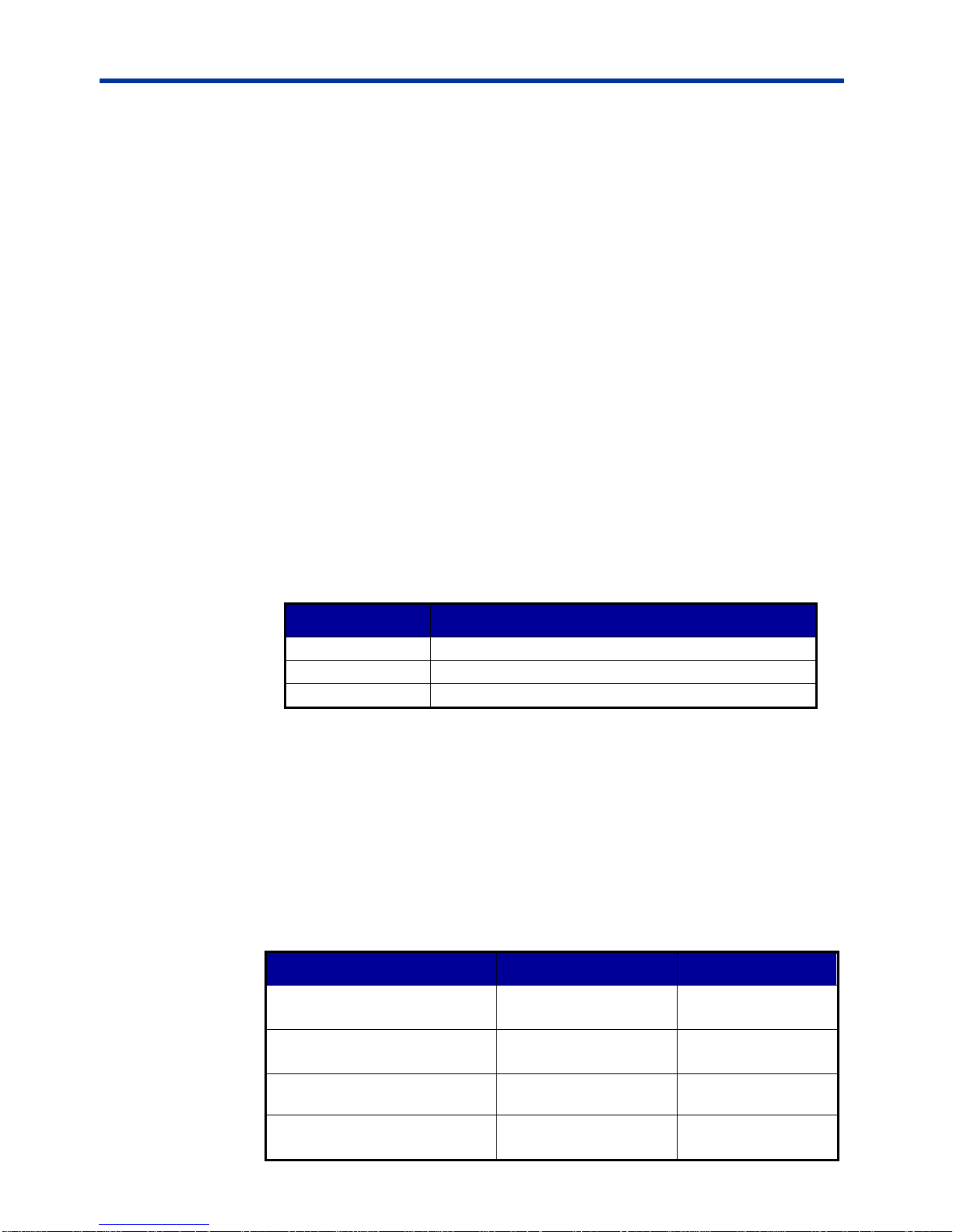
How to Contact
Microtronix
E-mail
Sales Information: sales@microtronix.com
Support Information: support@microtronix.com
Website
General Website: http://www.microtronix.com
FTP Upload Site: http://microtronix.leapfile.com
Phone Numbers
General: (01) 519-690-0091
Page 3 of 87
Page 4

DX-2200 – Dual-view 2x1 SDI Video Switcher
Table of Contents
Document Revision History .............................................................................................................................. 2
How to Contact Microtronix .............................................................................................................................. 3
E-mail............................................................................................................................................................ 3
Website ......................................................................................................................................................... 3
Phone Numbers ............................................................................................................................................ 3
Features ........................................................................................................................................................... 8
Introduction ...................................................................................................................................................... 9
Text Overlay OSD Features ......................................................................................................................... 9
Hardware ........................................................................................................................................................ 10
Power Requirements .................................................................................................................................. 10
Operation ....................................................................................................................................................... 10
Display Modes ............................................................................................................................................ 10
Display Mode 1: Full-screen 2x1 Switcher ............................................................................................. 11
Display Mode 2: Picture-in-Picture ......................................................................................................... 11
Display Mode 3: Dual view, Picture-and-Picture .................................................................................... 11
Display Mode 4: Split Screen .................................................................................................................. 11
Display Mode 5: Alpha Blended Overlay ................................................................................................ 11
Display Mode 6: Standby Switcher ......................................................................................................... 12
Display Mode 7: Dual-view, Vertically Stacked ...................................................................................... 12
Sample Outputs .......................................................................................................................................... 12
Default Startup Configuration ..................................................................................................................... 14
LED Status Indicators ................................................................................................................................. 14
Output Video Format .................................................................................................................................. 15
Video Output Modes 1 & 3 ...................................................................................................................... 15
Video Output Mode 2 .............................................................................................................................. 16
Default Output Video Mode .................................................................................................................... 16
Input Video Format ..................................................................................................................................... 16
Video Buffering and Delay .......................................................................................................................... 16
SERIAL & MANUAL Control ....................................................................................................................... 17
SERIAL Mode of Operation .................................................................................................................... 17
Serial Port Control Commands ........................................................................................................... 17
Input Selection SERIAL Commands ................................................................................................... 18
Input Auto Switch SERIAL Command ................................................................................................. 19
Alpha Blending Effects SERIAL Commands ....................................................................................... 20
Mode Control SERIAL Command ....................................................................................................... 24
Alpha Blended Overlay Size and Position SERIAL Commands ......................................................... 24
Picture-in-Picture Position & Size SERIAL Commands ...................................................................... 27
Alpha Blending Transparency SERIAL Command ............................................................................. 28
Baud Rate SERIAL Command ............................................................................................................ 30
Graphic Overlay SERIAL Commands ................................................................................................. 30
Sample Text Field Commands ............................................................................................................ 47
Low Level Text Control Commands .................................................................................................... 50
Frame Counter Overlay SERIAL Commands ..................................................................................... 51
Overlay Control SERIAL Commands .................................................................................................. 57
Layer Control SERIAL Commands ..................................................................................................... 57
Digital Zoom Command ...................................................................................................................... 60
User Interface Commands .................................................................................................................. 63
User Interface Function Configuration ................................................................................................ 63
Resetting DX-2200 Switches to Factory Default Configuration .......................................................... 64
Recommendations for DX-2200 Configuration ................................................................................... 65
DX-2200 Example Configuration Command File ................................................................................ 67
Output Video Format Command ......................................................................................................... 68
Configuration Flash Serial Commands ............................................................................................... 70
Other Serial Command Codes ............................................................................................................ 70
MANUAL Mode of Operation .................................................................................................................. 71
Page 4 of 87
Page 5

DX-2200 – Dual-view 2x1 SDI Video Switcher
Toggle Switch ...................................................................................................................................... 71
DIP Switch Settings ............................................................................................................................. 72
DX2200 Software Upload Utility ..................................................................................................................... 72
Firmware Update Procedure ...................................................................................................................... 72
Uploading Images ....................................................................................................................................... 72
Wingdings Font Table .................................................................................................................................... 74
Extended ASCII Fonts.................................................................................................................................... 75
Design Customizations .................................................................................................................................. 75
One Year Warranty ........................................................................................................................................ 76
Hardware .................................................................................................................................................... 76
Firmware ..................................................................................................................................................... 76
Limited Liability ........................................................................................................................................... 76
Appendix A: Updating IP Core On-Board Flash ............................................................................................ 77
Programming the Flash Device .................................................................................................................. 77
Appendix B: Internal Circuit Board Description .............................................................................................. 78
SDI Video Interfaces ................................................................................................................................... 78
RS-232 Serial Control Port ..................................................................................................................... 79
RS-232 3-Pin Header, J2 .................................................................................................................... 79
Power Requirements .................................................................................................................................. 79
Power Connectors .................................................................................................................................. 79
JTAG Header .......................................................................................................................................... 79
Reset Pushbutton SW1 .............................................................................................................................. 80
Board Dimensions ...................................................................................................................................... 80
Appendix C: Optional USB to RS-232 Serial Port Adapter ............................................................................ 81
Appendix D: Regulatory Compliance Information .......................................................................................... 82
Industry Canada (IC) .................................................................................................................................. 82
Federal Communications Commission (FCC) Declaration of Conformity .................................................. 82
CE Declaration of Conformity ..................................................................................................................... 83
Page 5 of 87
Page 6

DX-2200 – Dual-view 2x1 SDI Video Switcher
Listing of Tables
Table 1: Description of LED Status Indicators ................................................................................................ 15
Table 2: Serial Port Command Acknowledgement Codes .............................................................................. 18
Table 3: Function of the Inputs For Each Display Mode ................................................................................. 18
Table 4: Input Selection SERIAL Command Codes ....................................................................................... 19
Table 5: Input Auto Switch Serial Command Codes ....................................................................................... 20
Table 6: Alpha Blended Overlay Transition Effects ........................................................................................ 21
Table 7: Mode Control SERIAL Command Codes ......................................................................................... 24
Table 8: Alpha Blended Size and Position Control SERIAL Command Codes .............................................. 25
Table 9: PiP Control Serial Command Codes................................................................................................. 28
Table 10: Transparency SERIAL Command Codes ....................................................................................... 29
Table 11: Alpha Blended Overlay Mode Transparency SERIAL Command Codes ....................................... 29
Table 12: Text and Symbol Fonts ................................................................................................................... 34
Table 13: Graphic Overlay SERIAL Command Codes ................................................................................... 42
Table 14: Low Level Text Command Codes ................................................................................................... 50
Table 15: Frame Counter Overlay SERIAL Command Codes ....................................................................... 55
Table 16: Overlay Control SERIAL Command Codes .................................................................................... 57
Table 17: Layer Control SERIAL Command Codes ....................................................................................... 59
Table 18: Digital Zoom Command Codes ....................................................................................................... 61
Table 19: User Interface Command Codes .................................................................................................... 66
Table 20: Output Video Format Command Codes ......................................................................................... 69
Table 21: Flash Serial Command Codes ........................................................................................................ 70
Table 22: Other Serial Command Codes ........................................................................................................ 70
Table 23: Operation of 2-Position Momentary Toggle Switch ........................................................................ 71
Table 24: Operation of the 4-Position DIP Switch .......................................................................................... 72
Table 25: Windings Character Table .............................................................................................................. 74
Table 26: Extended ASCII Character Table ................................................................................................... 75
Table 27: RS-232 Serial Control Port DB9 Pin Assignments ......................................................................... 79
Table 28: RS-232 3-Pin Header, J2 ................................................................................................................ 79
Page 6 of 87
Page 7

DX-2200 – Dual-view 2x1 SDI Video Switcher
Listing of Figures
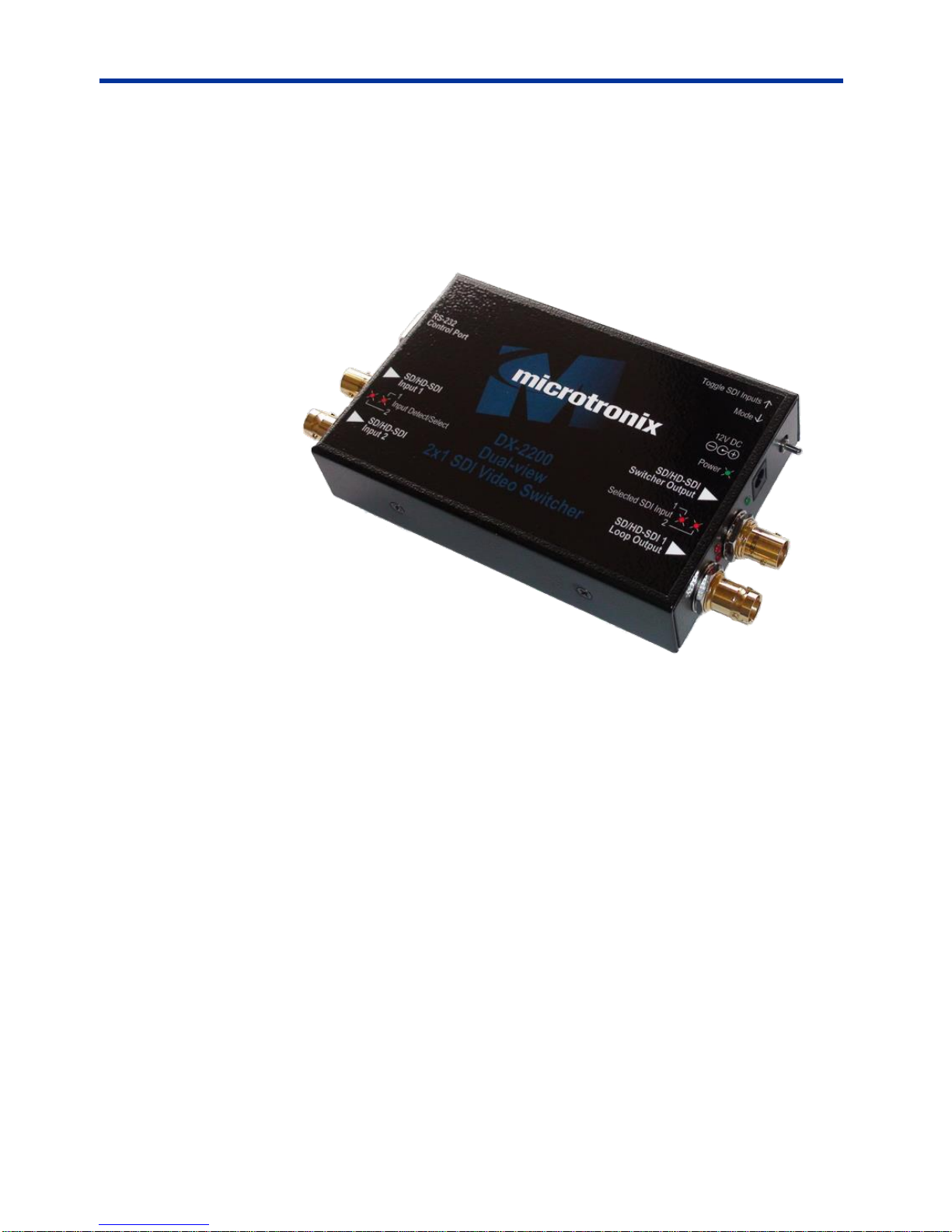
Figure 1: DX-2200 – Dual-view 2x1 SDI Video Switcher ................................................................................ 10
Figure 2: Digital Zoom PiP .............................................................................................................................. 12
Figure 3: Dual-view – Custom Picture-and-Picture display with text and time code Frame Counter ............. 13
Figure 4: Dual-view – Vertically Stacked with text OSD ................................................................................. 13
Figure 5: Alpha Blended PiP with Text Overlay OSD ..................................................................................... 13
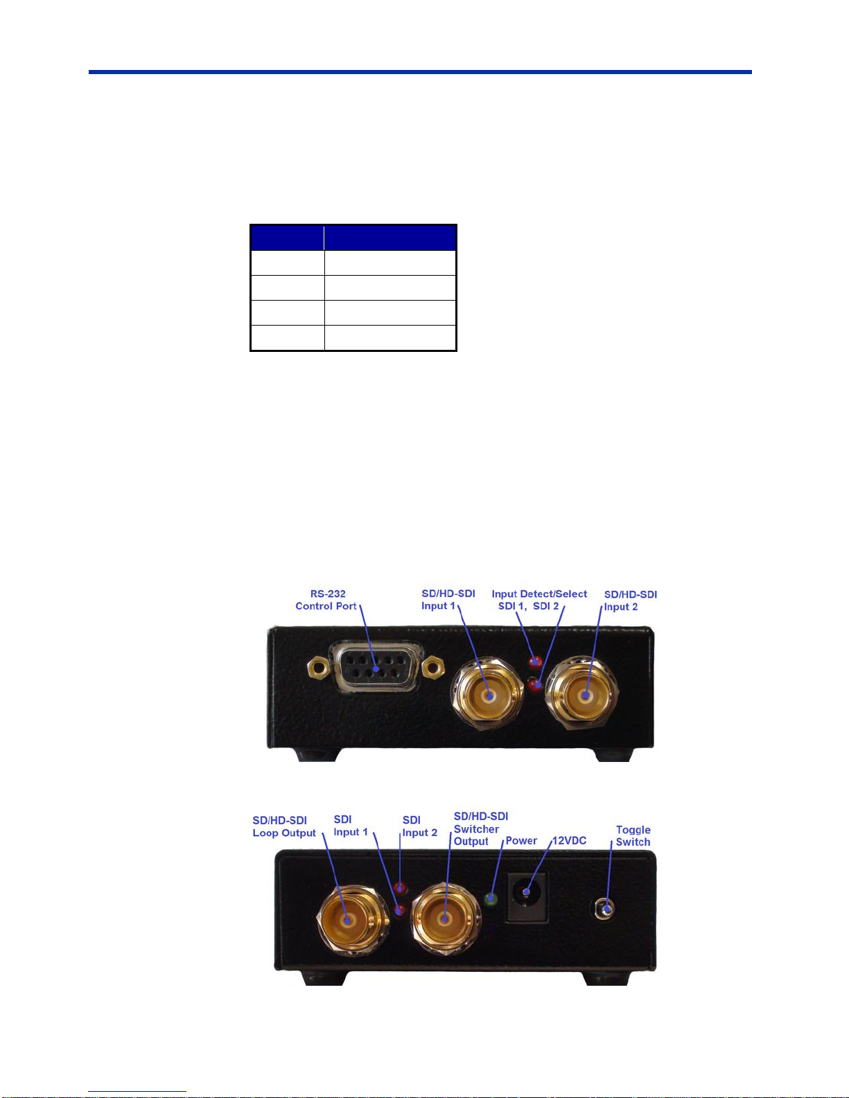
Figure 6: SDI Input LEDs ................................................................................................................................ 14
Figure 7: SDI Out & Power LEDs .................................................................................................................... 14
Figure 8: Alpha Blended Vertical Split column 400 – Example 1a ................................................................. 23
Figure 9: Alpha Blended Vertical Split column 900 – Example 1b ................................................................. 23
Figure 10: Alpha Blended with scaling – Example 1a ..................................................................................... 26
Figure 11: Alpha Blended Vertical split with frame counter – Example 1b ..................................................... 26
Figure 12: Samples of active text and graphic logo ........................................................................................ 33
Figure 13: Samples of transparent text and background ................................................................................ 34
Figure 14: Sample of the available Tahoma font sizes ................................................................................... 36
Figure 15: Character set - codes 20-7F and A0-FF ........................................................................................ 36
Figure 16: Sample of Rectangle, Target Marker and Text .............................................................................. 42
Figure 17: Sample of Corner Markers, Target and Text ................................................................................. 42
Figure 18: Example 1 - red text OSD with white background ......................................................................... 48
Figure 19: Example 2 – sample of default text ............................................................................................... 49
Figure 20: Frame Counter text display – Example 2 ...................................................................................... 54
Figure 21: Frame Counter text display – Example 3 ...................................................................................... 54
Figure 22: JTAG Cable Connection ................................................................................................................ 77
Figure 23: DX-2200 – Dual-view 2x1 SDI Switcher Board ............................................................................. 78
Figure 24: USB to DB9 RS-232 Serial Port Adapter Kit ................................................................................. 81
Page 7 of 87
Page 8

DX-2200 – Dual-view 2x1 SDI Video Switcher
Features
The key hardware features of the DX-2200 – Dual-view 2x1 SDI Video
Switcher (Model PN: DX-2200-SW-02) includes:
Two 75Ω SD/HD-SDI input ports
Two 75Ω SD/HD-SDI output ports
o One the Switcher output
o One loop through output of SDI input port 1
One DB9, RS-232 Serial Control Port
Note: With custom DX-2200 firmware, the RTS & CTS modem signals on
the DB9 Serial Port can be configured to operate as a second Serial
Data Port and function as RS-232 Receiver and Transmitter signals.
A custom serial “Y” cable is used to bring out the two ports.
Supported functionality:
Digital switching between 2 SDI inputs using switches or a serial control
port commands
Glitch-free video switching between SDI inputs and modes of operation
Video formats:
o 720p @ 25 / 29.97 / 30 / 50 / 59.94 / 60 fps
o 1080i @ 25 / 29.97 / 30 fps
o 1080p @ 23.98 / 24 / 25 / 29.97 / 30 fps
o 1080psf @ 23.98 / 24 / 25 / 29.97 / 30 fps
o NTSC @ 59.94 fps
o PAL @ 50 fps
Video Modes:
o 2x1 (Full-screen) Switcher
o Alpha blended Picture-in-Picture with size and position control,
o Dual view, Picture-and-Picture,
o Split screen,
o Alpha blended overlay, and
o Standby switcher.
Text overlay OSD:
o Up to 48 independent Graphic Fields
o Fields support Text, Rectangle, Corner Marker, Target Marker, and
Image Field types.
o Filled or open rectangles
o Size, color, transparency and position control
o Configurable background color for text
o Alpha blended text and background
o Alpha blending of graphic fields
Output video Frame Counter text overlay display,
Alpha blended video switching transition effects,
Digital Zoom: 28 steps of 0.25 from 1x to 8x,
User defined operation of DIP & Toggle switches
NOTE: The text/graphics overlay OSD is supported in progressive but not in
either interlaced or Progressive segmented Frame (PsF) video formats.
Page 8 of 87
Page 9

DX-2200 – Dual-view 2x1 SDI Video Switcher
Introduction
The Microtronix DX-2200 – Dual-view 2x1 SDI Video Switcher (Model Part
Number: DX-2200-SW-02) is a high performance dual input SDI Video Switcher
supporting enhanced video capabilities including: 2x1 glitch-free video switching,
picture-in-picture (PiP), picture-and-picture (PAP), Split-Screen, text overlay / on
screen display (OSD), Alpha Blending and Digital Zoom. The product is available
as a stand-alone product in an aluminum enclosure or as an open printed circuit
board for incorporation into embedded video system. The unit is designed for use
in broadcast, professional video recording and high-end surveillance applications.
To ensure glitch-free continuous/artifact free video output, the two input SDI video
streams are firstly frame synchronized then switched during the vertical interval
period when a frame is complete. Additional frame buffers are used to eliminate
artifacts which can occur when operating in a PiP or PAP mode during which
scalers or clippers are being used.
When processing interlaced video, a field detector is used to synchronize the input
frame buffers and video processing to ensure the correct alignment of the video
fields when switching between the video streams or swapping PiP or PAP
displays. The output video format can be the same as the format detect on the
SDI input 1 (SDI-1) video source, or can be programmed independently.
The product supports synchronized switching of SD / HD SDI video formats. Text
overlay is supported on progressive video only.
The units can be configured to retain the user configuration in on-board flash
during power ON / OFF power cycles.
Text Overlay OSD Features
The DX-2200 supports text overlay OSD in all display modes of operation.
Features of the text overlay OSD include:
1) Display of 48 independent Fields of up to 96 characters.
2) Alpha blending of the text on the video screen.
3) Active Frame Counter.
4) Independent color selection of text fields.
5) Configurable background color.
6) Opacity control.
7) Independent ON/OFF control of text fields.
8) X-Y position control.
9) Permanent retention of text fields in flash memory.
10) Eight font / text size combinations.
The text is supplied to the DX-2200 Switcher through the RS-232 serial port. The
user can optionally store the text fields in the on-board flash in which case they will
be retained power ON/OFF power cycles.
NOTE: The Text/graphic overlay feature is supported in progressive video formats
Page 9 of 87
only.
Page 10
DX-2200 – Dual-view 2x1 SDI Video Switcher
Hardware
Operation
The DX-2200 – Dual-view 2x1 SDI Video Switcher is available as a stand-alone
product supplied in an enclosure as show in Figure 1 below or as an open-frame
board (for building into embedded video system) as shown in Figure 23 shown in
Appendix B.
Figure 1: DX-2200 – Dual-view 2x1 SDI Video Switcher
Power Requirements
The DX-2200 Switcher is powered from a standard 5.5mm center positive 5-12Vdc
1.3A 10W (120/240VAC) regulated switching power adapter.
Display Modes
The DX-2200 Switcher supports the display of the SDI video either full-screen or in
a variety of dual-viewer window modes. The display modes include:
o Mode 1: Full-screen 2x1 Switcher
o Mode 2: Picture-in-Picture,
o Mode 3: Dual view, Picture-and-Picture – side-by-side,
o Mode 4: Split screen,
o Mode 5: Alpha blended overlay, and
o Mode 6: Standby Switcher.
o Mode 7: Dual view, vertically stacked
Page 10 of 87
Page 11

DX-2200 – Dual-view 2x1 SDI Video Switcher
The Text Overlay (On Screen Display) is supported in all Display Modes for
progressive video formats only. The Text Overlay is always the top layer in the
output video mix.
The Frame Counter capability is supported in all Display Modes for progressive
video formats only.
The Zoom capability is supported in all Display Modes. Either input can be
zoomed. Except in Display Mode 4 (Split Screen), the zoom can be configured
either as zoom percentage and center position, or as top left corner and size. In
Display Mode 4, only the zoom factor can be set and the zoom position cannot be
changed.
Display Mode 1: Full-screen 2x1 Switcher
In the Full-screen Switcher mode, the selected input is displayed full screen and
the unit can switch from one input to the other.
Display Mode 2: Picture-in-Picture
In Picture-in-Picture (PiP) mode, the selected input is displayed full and the other
input is displayed as a picture in picture with configurable size, position and
transparency (alpha blending). Using either the toggle switch or serial commands,
the DX-2200 can switch between the inputs selected for display full screen and for
the PiP.
Display Mode 3: Dual view, Picture-and-Picture
In the Picture-and-Picture (PAP) mode, the images are scaled to display both
sources side by side. The selected input is displayed on the left side of the screen,
and the other input is displayed on the right.
Using either the toggle switch or serial commands, the DX-2200 can switch inputs
to interchange the left and right side images.
Display Mode 4: Split Screen
In the Split Screen mode, half of each input image is displayed. The left half of the
selected input is displayed on the left side of the output video, and the right half of
the other input is displayed on the right side of the output video.
Using either the toggle switch or serial commands, the DX-2200 can switch inputs
to interchange the left and right side images.
Display Mode 5: Alpha Blended Overlay
In the Alpha Blended Overlay mode, both images are displayed with configurable
alpha blending of the images. The selected input is displayed over a black
background, with the non-selected layer mixed on top of it. The alpha of each
input can be adjusted and the two images can be zoomed, moved, and re-sized in
the output video.
Page 11 of 87
Page 12

DX-2200 – Dual-view 2x1 SDI Video Switcher
Display Mode 6: Standby Switcher
The Standby Switcher automatically switches between the two inputs sources.
The selected input is the preferred source, but if no signal is available the other
source will be displayed. The DX-2200 returns to the preferred source if the signal
is restored.
Display Mode 7: Dual-view, Vertically Stacked
In the dual-view vertically stacked mode, the images are scaled to display both
sources one above the other. The selected input is displayed at the top of the
screen, and the other input is displayed below it.
Using either the toggle switch or serial commands, the DX-2200 can switch inputs
to interchange the upper and lower images.
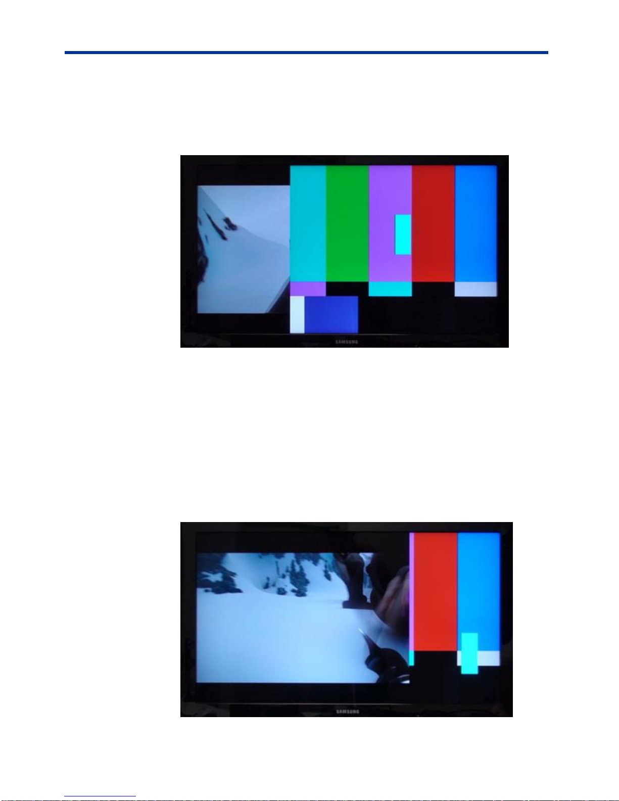
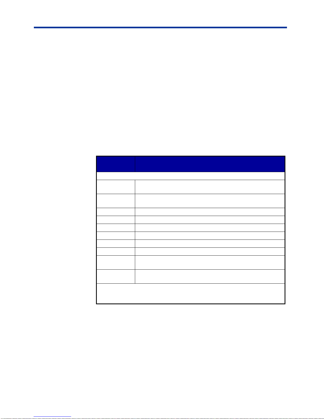
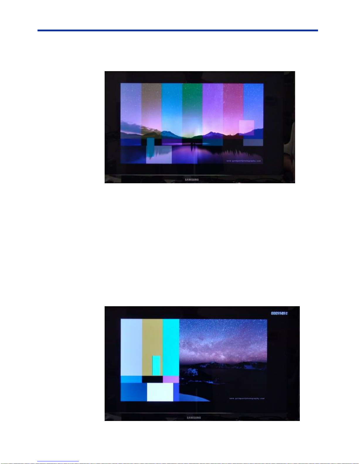
Sample Outputs
Samples of the various output display modes are shown in the following figures.
Figure 2: Digital Zoom PiP
Page 12 of 87
Page 13

DX-2200 – Dual-view 2x1 SDI Video Switcher
Figure 3: Dual-view – Custom Picture-and-Picture display with
text and time code Frame Counter
Figure 4: Dual-view – Vertically Stacked with text OSD
Figure 5: Alpha Blended PiP with Text Overlay OSD
Page 13 of 87
Page 14
DX-2200 – Dual-view 2x1 SDI Video Switcher
Switch
Setting
1
Off 2 Off 3 Off 4 Off
Default Startup Configuration
The power up configuration is determined by both the DIP switch setting and the
configuration saved in flash. The factory default setting has no saved configuration
in flash and the following DIP switch settings:
Table 4: Default DIP switch (SW4) setting
The factory default power on or reset configuration is set to operate in Mode 1, the
full-screen 2x1 video switcher. The unit will initially display SDI input 1 (SDI-1) on
the output. If there is no input signal (or if it cannot be properly detected), the SDI
output will display black.
User specific setups can be stored in flash to enable the DX-2200 to start in other
modes, for example, with a PiP or PAP configuration or with a preset text overlay.
LED Status Indicators
The location of the 5 LEDs is show in the following two figures.
Figure 6: SDI Input LEDs
Figure 7: SDI Out & Power LEDs
Page 14 of 87
Page 15
DX-2200 – Dual-view 2x1 SDI Video Switcher
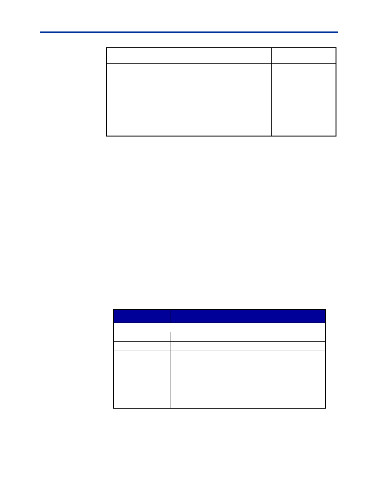
LED
Color
Use
Mode of Operation
Input-Top
(Board D4)
Red
SDI Input 1
OFF: SDI 1 input not available
Flashing: SDI 1 input available
ON: SDI 1 input available and selected as primary input
Input-
Bottom
(Board D4)
Red
SDI Input 2
OFF: SDI 2 input not available
Flashing: SDI 2 input available
ON: SDI 2 input available and selected as primary input
Input
(Board D3)
Green
Power
ON: Power ok
Output-Top
(Board D5)
Red
SDI Input1
Out
OFF: SDI 1 input not available
Flashing: SDI 1 input available
ON: SDI 1 input available and selected as primary input
Output-
Bottom
(Board D5)
Red
SDI Input 2
Out
OFF: SDI 2 input not available
Flashing: SDI 2 input available
ON: SDI 2 input available and selected as primary input
The operation of the LEDs is summarized in Table 1 below.
Table 1: Description of LED Status Indicators
Output Video Format
The settings of the DX-2200 and the video source connected to SDI input 1
(SDI-1) determine the output video format. The output video has three Modes of
operation:
Output Mode 1: The output video format is the same as the SDI Input 1 format.
Output Mode 2: The output video format (resolution and frame rate) is set to a
specific format that was set by a SERIAL Control command.
Output Mode 3: The output video format is the same as the SDI Input 1 format
and the clock frequency is locked to the source frequency.
Video Output Modes 1 & 3
The default output video format is Mode 1 in which the SDI output is the same
format as on SDI input 1. The mode can be changed by a SERIAL control
command. Refer to Output Format SERIAL Command Codes (See Table 20) for
details of the commands used to change the output video modes.
When operating in Output Mode 1 or Mode 3 (assuming the SDI-1 video source is
recognized as one of the supported video formats) the DX-2200 will reconfigure
itself to match the output video to the detected input format. Reconfiguration of the
output video format momentarily stops video output. When no video is connected
to SDI input 1, or if the format is not recognized, the unit will continue to operate
without changing the output video format.
Page 15 of 87
Page 16

DX-2200 – Dual-view 2x1 SDI Video Switcher
Video Output Mode 2
When operating in Video Output Mode 2, the output video resolution and frame
rate is determined exclusively by the setting programmed into the DX-2200 by a
SERIAL Control command. See commands listed in Table 20.
Default Output Video Mode
The factory default output video format is 720p 60 fps. If the unit is powered up, or
reset by the factory reset SERIAL command, or reset by pressing the reset
pushbutton when the board is out of the enclosure, without a video source
connected to SDI input 1, then it will operate at 720p, 60 fps. The default video
mode can be changed by saving a configuration to flash while the unit is operating
with a different video format.
Input Video Format
When a supported video format is connected to one of the SDI Input connectors,
the DX-2200 will recognize the signal and illuminate the corresponding LED.
Depending on the operating settings of the DX-2200, the format of the video
connected to SDI input 1 may determine the output video format. If the SDI-1
video format is changed the unit may switch to a different output video format. The
format of the video source connected to SDI Input 2 (SDI-2) never has any effect
on the output format.
If the video source connected to SDI Input 2 has a different resolution or frame
rate than the source connected to SDI Input 1, the DX-2200 will apply frame
repetition, frame dropping, or scaling as required to convert the video to the format
that is being output.
The DX-2200 does not convert between progressive and interlaced video formats.
If the video source connected to an input is interlaced (or PsF) when the output
format is progressive, or if the video source is progressive when the output format
is interlaced (or PsF), then the Input will not be recognized. The indicator LED will
be OFF and the video source cannot be selected for display.
The Text Overlay OSD remains available when the input video sources are not
present.
Video Buffering and Delay
When operating with progressive video, the DX-2200 uses two frame buffers in
each input path. Each buffer will delay by a minimum of one frame and a
maximum of two frames, giving a total delay of between two and four frames on
each input. The frame buffers account for the majority of the video delay through
the DX-2200. Other elements in the video processing path will add additional
delays of a few lines of video.
When operating in interlaced video modes, an additional frame buffer is required
in the video output path. This buffer adds an additional delay of between one and
two frames to the video path.
Page 16 of 87
Page 17

DX-2200 – Dual-view 2x1 SDI Video Switcher
The actual delay will depend on the timing of the connection of the input signals
and the phase relationship between the inputs if they are not locked to each other.
Depending on operation conditions, the video delay may remain constant, or may
vary over time. The DX-2200 does not require the two video inputs to be
synchronized, and the output video can either be locked in frequency to input 1, or
use an internally video clock. When different video clocks are used, small
differences between the clocks will cause the video delay to change. If the output
clock is slower than the input clock, video will accumulate in the frame buffers until
a frame is dropped to prevent buffer overflow. When the output clock is faster than
the input clock, the length of video in the buffers will decrease until a frame must
be repeated to prevent buffer underflow. If all video clocks are derived from the
same source and are identical in frequency, the delay through the DX-2200 will
remain constant.
SERIAL & MANUAL Control
The DX-2200 Switcher has two methods of control: SERIAL Control using the
RS232 port, and MANUAL Control using the DIP switch and Toggle switch.
SERIAL Control allows control full of the capabilities of the DX-2200, and
MANUAL Control provides a subset of functions.
SERIAL Control is always active. In the factory default configuration the Toggle
Switch and DIP switch are active.
The functions of the DIP switch and Toggle switch can be reconfigured by SERIAL
Control commands to customize the Switcher so that the controls provide the set
of functions required for a specific user application. The modified configuration can
be saved on board in the flash configuration memory
SERIAL Mode of Operation
When SERIAL control is used, the DX-2200 Switcher is controlled via commands
sent to the DB9 Serial Control Port.
The serial port of the computer connected to the DX-2200 should be configured for
115,200 baud, 1 stop bit, and no flow control.
Microtronix sells an optional USB to DB9 RS-232 Serial Port Adapter Kit,
(PN: 811-USB-RS232-Kit) which can be used to connect the USB port of a PC or
laptop to the Serial Port of the DX-2200. (See Appendix C.)
SERIAL PORT CONTROL COMMANDS
In the SERIAL mode commands sent to the Serial Control Port control the
operation of the DX-2200. Commands consist of ASCII alpha-numeric codes and
are not case sensitive. All serial commands are terminated with a carriage return
(CR), a line feed (LF), or a semicolon. The use of a semicolon terminator allows
more than 1 command per line to improve readability of script files.
Commands may be sent directly to the DX -2200 one character at a time using a
terminal program running on a connected computer, or they may be developed in
a text editor such as Notepad and then uploaded to the DX-2200 by the terminal
Page 17 of 87
Page 18
DX-2200 – Dual-view 2x1 SDI Video Switcher
Response Code
Mode of Operation
+
Valid command received
-
Invalid command received
*
Valid CR, LF, or semicolon received
Mode of Operation
Selected Input
Non-Selected Input
Display Mode 1:
Full-screen 2x1 Switcher
Full Screen Output
Not Visible
Display Mode 2:
Picture-in-Picture
Full Screen Background
PiP
Display Mode 3: Dual view,
Picture-and-Picture
Left Image
Right Image
Display Mode 4:
Split Screen
Left half of the source is
is displayed as the left
Right half of the
source is displayed
program. The second method has the advantage of allowing the commands to be
saved, viewed, edited and resent. The text editor used must save the configuration
files as 8 bit ASCII data.
Space or tab characters before a command or trailing a command are ignored, as
are spaces or tabs following a comma that separates parameters within a
command. Any characters on a line following a tick (') character are treated as
comments. A comment may begin after a delimiter, or may follow a command with
or without spaces or tabs between the command and the comment.
ASCII string parameters are delimited with quotation marks. If a quotation mark or
backslash character is required within a string (for example to display as part of a
text overlay), then it must be preceded by a backslash character.
Valid and invalid serial commands are acknowledged with a ‘+’ and ‘-’ response
respectively. Carriage return, line feed, or semicolon characters without a
preceding command are acknowledged with a ‘*’.
The command codes are extensible, additional commands and functionality can
be added as required. Contact Microtronix sales or technical support with your
requirements.
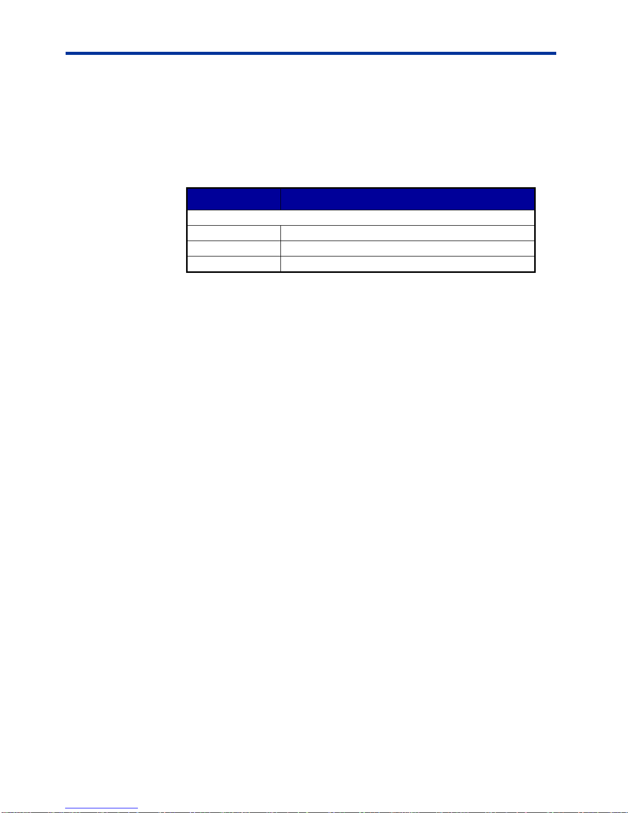
Table 2: Serial Port Command Acknowledgement Codes
INPUT SELECTION SERIAL COMMANDS
The Input Selection SERIAL Commands, (see Table 4, Table 1, Figure 22), are
used to select the SDI input. Switching between SDI inputs is supported at all
video resolutions.
The following table shows the function of the selected input and the non-selected
input for each Display Mode.
Table 3: Function of the Inputs For Each Display Mode
Page 18 of 87
Page 19
DX-2200 – Dual-view 2x1 SDI Video Switcher
half of the output video
an the right half of
the output video
Display Mode 5:
Alpha Blended Overlay
Mixed onto a black
background.
Mixed on top of the
selected input and
background
Display Mode 6:
Standby Switcher
The preferred source.
Displayed full screen if
present
Alternate source
displayed when
preferred source not
present
Display Mode 7:
Dual-view, Vertically Stacked
Displayed at the top of
the screen.
Displayed at the
bottom of the screen
Command Code
Mode of Operation
Input Selection Commands
I1
Select input 1
I2
Select input 2
IT
Swap Inputs
T
In Display Mode 5, change the alpha of the nonselected input to the inverse of the current value to
reverse visibility of the inputs.
In all other Display Modes, this command performs
the same functions as the ‘IT’ command.
The ‘I1’ and ‘I2’ Input Selection Commands can select a specific input, or the ‘IT’
command can be used to select the other input.
The ‘T’ command has a function that depends on the operating mode. In Alpha
Blended Overlay Mode, the ‘T’ command changes the alpha of the non-selected
input to the inverse of the current value. When Alpha Blended Overlay Mode has
the two inputs in the same location in the output video, the ‘T’ command has the
effect of reversing the visibility between the two layers. In all other modes, the ‘T’
command performs the same function as the ‘IT’ command.
NOTE: Using the ‘T’ command to apply the inverse alpha to the non-selected
input provides the highest quality switch between the two inputs when
operating in Alpha Blended Overlay mode when both inputs are overlaid
with partial visibility. If Alpha Blended Overlay mode is reconfigured so
that the two inputs are not overlaid, then the ‘T’ command cannot be used
as a switching command and ‘I1’, ‘I2’, or ‘IT’ must be used instead.
Table 4: Input Selection SERIAL Command Codes
INPUT AUTO SWITCH SERIAL COMMAND
The Input Auto Switch Commands are used to set auto switch mode on or off.
Page 19 of 87
When auto switch is on, the DX-2200 will automatically switch inputs if the
selected input source is not available for display, but the other input is available.
Page 20
DX-2200 – Dual-view 2x1 SDI Video Switcher
Command Code
Mode of Operation
Input Selection Commands
IA
Toggle auto switch between on / off
IA0
Set auto switch off
IA1
Set auto switch on
Mode 5 (Alpha blended Overlay) does not support auto switch.
Mode 6 (Standby Switcher) is not affected by the auto switch setting and will
always switch when the preferred input is not present but the other input is
present.
Table 5: Input Auto Switch Serial Command Codes
ALPHA BLENDING EFFECTS SERIAL COMMANDS
In the Alpha Blended Overlay Mode (Mode 5), the DX-2200 uses alpha blending to
provide Transition Effects and Horizontal or Vertical Alpha Split modes. The
difference between the wipe Transition Effects and the Alpha Split modes is that
the transition effects automatically move the alpha transition point across the video
after the effect has been triggered, and the Alpha Split modes allow manual
control of the position of the alpha transition.
In the Alpha Blended Overlay mode, the video from both inputs is mixed into the
output video and each video source can be independently sized and positioned in
the output video. The selected input is mixed onto a black background. The other
input is mixed on top of the selected input. The Alpha Blending effects operate
only within the output video window of the source to which the effect is applied and
change the alpha blending of the source as it is mixed into the output video.
When Alpha Blending Effects are applied to the selected layer, they change the
transparency of the layer and determine the mix between the selected layer and
the black background behind it. When applied to the non-selected layer, the Alpha
Blending Effects determine the mix between the non-selected layer and the layers
behind it, which could be the black background, the selected layer, or a mix
between them.
When the two inputs are the same size and in the same position in the output
video, the Alpha Blending effects can be used to switch from one input to the other
by changing the top layer in the mix (the non-selected layer) from fully visible to
fully transparent. The Transition Effects will then provide an automatic progressive
switch from one image to the other, and the Horizontal / Vertical Alpha Split modes
will provide a split image where the change from one layer to the other can be set
(and changed) by Serial Commands.
The Alpha Blending Commands beginning with ‘TS’ affect the selected layer, and
the commands beginning ‘TP’ affect the non-selected layer.
Page 20 of 87
Page 21
DX-2200 – Dual-view 2x1 SDI Video Switcher
Command
Code
Mode of Operation
Transition Effect Commands
TP0
Non-selected Layer: Complete any transition effect
immediately or exit from the Alpha Split Modes
TP1
Non-selected Layer: Wipe from Top to Bottom
TP2
Non-selected Layer: Wipe from Bottom to Top
TP3
Non-selected Layer: Wipe from Right to Left
TP4
Non-selected Layer: Wipe from Left to Right
TP5
Non-selected Layer: Fade
TP6
Non-selected Layer: Horizontal Alpha Split
TP7
Non-selected Layer: Vertical Alpha Split
The DX-2200 provides Wipe effects in 4 directions and a fade effect. The rate of
change for the Wipe effect is programmable in units of pixels per frame with the
‘TPI’ or ‘TSI’ command. The rate of change for the fade is programmable in units
of alpha per frame by using the ‘TPA’ or ‘TSA’ command. After the Transition
Effect completes, the Alpha blending value for the input is changed to a new
value.
NOTE: If other commands that change the alpha of the transitioning input are
executed during a Transition Effect, they won’t be applied until the
transition completes.
The Horizontal Alpha Split and Vertical Alpha Split modes do not automatically
move the transition point. They operate continuously until disabled by the ‘TP0’ or
‘TS0’ command, or by selecting a different Alpha Blending Effect. For each video
frame, the initial alpha value is applied to the pixels before the transition row or
column. For pixels after the transition point, a second alpha is applied. The ‘TPS’
or ‘TSS’ command sets the transition point to a specific row or column position.
The row or column refers to a position within the output video window that the
effect is applied to. For example if Input 1 is displayed in a 640x360 pixel window,
then the range of transition points for the vertical split can be set at positions from
0 to 639 pixels, regardless of the output video format or the location of the
640x360 pixel window in the video. Unlike the Transition Effects, the Alpha Split
modes do not permanently change the alpha of the input.
For all Alpha Blending Effects, the default alpha after the transition is the inverse
of the initial value; A fully visible layer changes to fully transparent and vice-versa.
NOTE: If the initial alpha is set for half visibility, the transition effects will change
from half visibility to the inverse, also half visibility, and no change will be
visible on the output.
The ‘TPB’ or ‘TSB’ command can be used to set a specific alpha value to be used
after the transition instead of the default alpha. If the alpha set in the command is
the same as the initial alpha, then no change will be visible at the output.
Table 6: Alpha Blended Overlay Transition Effects
Page 21 of 87
Page 22
DX-2200 – Dual-view 2x1 SDI Video Switcher
TPInnnn
Non-selected Layer: Set the transition speed in units of pixels
per frame for the wipe modes.
‘nnnn’ is a positive integer between 1 and 4 digits in length.
TPAnnnn
Non-selected Layer: Set the transition speed for the fade mode
in units of alpha change per frame.
‘nnnn’ is a positive integer between 1 and 4 digits in length and
between 1 and 255 in value.
TPSnnnn
Non-selected Layer: Set the transition point for the Split Screen
Modes. ‘nnnn’ is the row or column number and can be
between one and four digits in length.
TPBnnnn
Non-selected Layer: Set the alpha value used in the Horizontal
and Vertical Alpha Split modes for pixels after the transition
point. ‘nnnn’ is an integer of between one and four digits in
length. The valid range for alpha is 0 to 255.Setting a value
greater than 255 causes the DX-2200 to use the default alpha,
which is the inverse of the initial alpha.
TS0
Selected Layer: Complete any transition effect immediately or
exit from the Alpha Split modes.
TS1
Selected Layer: Wipe from Top to Bottom
TS2
Selected Layer: Wipe from Bottom to Top
TS3
Selected Layer: Wipe from Right to Left
TS4
Selected Layer: Wipe from Left to Right
TS5
Selected Layer: Fade
TS6
Selected Layer: Horizontal Alpha Split
TS7
Selected Layer: Vertical Alpha Split
TSInnnn
Selected Layer: Set the transition speed in units of pixels per
frame for the wipe modes.
‘nnnn’ is a positive integer between 1 and 4 digits in length.
TSAnnnn
Selected Layer: Set the transition speed for the fade mode in
units of alpha change per frame.
‘nnnn’ is a positive integer between 1 and 4 digits in length and
between 1 and 255 in value.
TSSnnnn
Selected Layer: Set the transition point for the Split Screen
Modes. ‘nnnn’ is the row or column number and can be
between one and four digits in length.
TSBnnnn
Selected Layer: Set the alpha value used in the Horizontal and
Vertical Alpha Split modes for pixels after the transition point.
‘nnnn’ is a number of between one and four digits in length. The
valid range for alpha is 0 to 255.Setting a value greater than
255 causes the DX-2200 to use the default alpha, which is the
inverse of the initial alpha.
Example 1a:
Set the DX-2200 to the Alpha Blended Overlay Mode (Mode 5),
Set the alpha to full visibilty to provide a hard switch between the two input
images, and
Use the Vertical Alpha Split Mode to split the screen vertically with the split
Page 22 of 87
position at column 400.
Page 23
DX-2200 – Dual-view 2x1 SDI Video Switcher
The SERIAL Commands are as follows:
M5
A0
TPS400
TP7
Figure 8: Alpha Blended Vertical Split column 400 – Example 1a
NOTE: It is possible for a user to create special wipe effects by writing software on
a PC to issue a continuous string of TPSxxx SERIAL commands to wipe
the video across the display as desired by the user.
Example 1b:
Starting from Example 1, move the split position to column 900.
TPS900
Figure 9: Alpha Blended Vertical Split column 900 – Example 1b
Page 23 of 87
Page 24
DX-2200 – Dual-view 2x1 SDI Video Switcher
Command Code
Mode of Operation
Mode Control Commands
M1
Full screen 2x1 switcher mode
M2
PiP mode
M3
PAP (side-by-side) mode
M4
Split-screen mode
M5
Alpha Blended Overlay
M6
Standby switcher mode
M7
Vertcially Stacked mode
MODE CONTROL SERIAL COMMAND
The Mode Control SERIAL Command selects between: 2x1 Full-screen Switcher,
PiP, PAP Split Screen, Alpha Blended Overlay, Standby Switcher, and the
Vertically Stacked modes of operation.
The Mode Commands are listed in Table 7 below.
Table 7: Mode Control SERIAL Command Codes
ALPHA BLENDED OVERLAY SIZE AND POSITION SERIAL COMMANDS
When operating in Alpha Blended Mode, the DX-2200 allows the size and position
of the output video windows corresponding to the selected and non-selected
inputs to be changed. By default, both windows occupy the full screen.
The video window of the selected input mixes onto a black background. The ‘BS’
commands control the size and position of the selected input’s window. The nonselected input is mixed on top of the video window of the selected input and the
black background. The ‘BP’ commands control the size and position of the nonselected input’s window.
The size and position of the output windows can be set either in pixels, or as a
percentage of the output video size. To specify percentage, include a ‘%’
character after the size. If the value for any parameter is set to ‘0’ without a ‘%’
character, the DX-2200 will use the default value for that parameter.
If either the width or height parameters for a window are set to ‘9999’, then the
DX-2200 will calculate a value for that parameter to preserve the aspect ratio of
the input video. If both the width and height are set to ‘9999’, then the video will be
full screen.
The minimum size (width or height) for a window is 32 pixels. The DX-2200 will
accept a smaller value in the commands, but will never display less than 32x32
pixels.
If a window size larger than full screen is specified, the DX-2200 will reduce the
size to full screen. If a position and size are specified that causes a window to
Page 24 of 87
Page 25
DX-2200 – Dual-view 2x1 SDI Video Switcher
Command
Code
Mode of Operation
Mode Control Commands
BPXnnnn
Set the top left corner X position of the non-selected input
window
BPYnnnn
Set the top left corner Y position of the non-selected input
window
BPWnnnn
Set the width of the non-selected input window
BPHnnnn
Set the height of the non-selected input window
BSXnnnn
Set the top left corner X position of the selected input window
BSYnnnnn
Set the top left corner Y position of the selected input window
BSWnnnn
Set the width of the selected input window
BSHnnnn
Set the height of the selected input window
BP0
Reset the Size and Position of the non-selected input window
to Default
BS0
Reset the Size and Position of the selected input window to
Default
Where ‘nnnn’ can be a number of pixels between one and four digits in length,
or be followed by a ‘%’ sign to specify a percentage of the output video size,
eg ‘50%’. When specified in %, the value can be an integer between 0 to 100.
extend beyond the video, the DX-2200 will change the x and y position as required
to fit the requested window size into the video. It is not possible to clip the video by
placing a window partially off screen.
NOTE: If the window size is full screen, then it is not possible to move the window
because any change in position would cause the window to extend off
screen.
If these commands are executed in a mode other than Alpha Blended Overlay, the
parameters are stored by the DX-2200, but won’t have any effect until Alpha
Bended Overlay mode is selected.
For interlaced video, the vertical position and height has a resolution of two pixels.
Table 8: Alpha Blended Size and Position Control SERIAL
Command Codes
Example 1a:
Select the Alpha Blended Overlay Mode and scale both inputs to 1000 x 562
pixels and position them in the center of the output video. This example is
designed for use when the switcher operates with 720p output video.
The SERIAL commands are as follows:
M5
BPW1000
BSW1000
BPH562
BSH562
BPX140
Page 25 of 87
Page 26
DX-2200 – Dual-view 2x1 SDI Video Switcher
BSX140
BPY80
BSY80
Figure 10: Alpha Blended with scaling – Example 1a
Example 1b:
Starting from Example 1, display the Frame Count in the upper right corner of the
video, change to the alpha Vertical Alpha Split Mode with full visibility, and position
the split at column 400. Note that the column number refers to the columns of the
scaled output image, not to the input video size.
SFM4
SF1X2000
SF1Y0025
A0
TP7
TPS400
Figure 11: Alpha Blended Vertical split with frame counter –
Example 1b
Page 26 of 87
Page 27

DX-2200 – Dual-view 2x1 SDI Video Switcher
PICTURE-IN-PICTURE POSITION & SIZE SERIAL COMMANDS
The position and size of the Picture-in-Picture (PiP) display is selected through
character commands sent via the RS-232 port per Table 9 below.
The commands P1, P2, P3 and P4 set the PiP position to predefined values and
take effect immediately. The pre-defined positions are referenced to the four
corners of the screen and include a default horizontal and vertical offset from the
corner that depends on the video resolution. The PAnnnn and PBnnnn commands
may be used to change the offsets. If the combination of PiP size and the offsets
does not fit within the output video, the offsets will be automatically reduced as
required.
The commands PS01 through PS16 set the Pip size to predefined widths in units
of 16ths of the screen width with height set to maintain the source video aspect
ratio of the source. The W, H, X, and Y commands are used to configure a custom
size and position of the PiP and do not take effect until a PU or PR command is
received. This allows all parameters to be configured and then applied
simultaneously.
The PU (PiP update) command sets the PiP size and position to values selected
by W, H, X and Y commands. This command ensures the PiP window is not larger
than the output video stream (display screen) and will ensure the entire PiP
window is visible to the user. If the selected position would result in the PiP
window being partially off-screen, the position will be adjusted so that no part of
the PiP window is off-screen. For example, in the 1280x720 mode, if the PiP size
is 640x360 and the selected PiP position is 700 pixels right and 400 pixels down,
the PU command will place the window at 640 pixels right and 360 pixels down so
it is completely visible.
The PR (PiP ratio) command is the same as the PU command except it ignores
the height set by the H command and sets the height based on the width to keep
the aspect ratio of the input video source. For example, if the command sequence
is W0480, H0300, PR, the size of the PiP window will be 480x270 pixels.
Page 27 of 87
Page 28

DX-2200 – Dual-view 2x1 SDI Video Switcher
Command
Code
Mode of Operation
Pn – PiP Commands
P1
PiP upper right with preset size
P2
PiP lower right with preset size
P3
PiP upper left with preset size
P4
PiP lower left with preset size
PSnn
Set the PiP size used with the predefined PiP positions. The
width is set in units of 16ths of the output video width. For
example PS05 set the width to 5/16ths of the video width.
PAxxxx
Set the horizontal gap in pixels between the reference corner and
the Pip window when using the predefined PiP positions. Enter
the value 9999 to use the default.
PBxxxx
Set the vertical gap in pixels between the reference corner and
the Pip window when using the predefined PiP positions. Enter
the value 9999 to use the default.
PU
PiP update – sets PiP size and position to values selected with
W, H, X and Y commands
PR
PiP update, fixed aspect ratio – sets PiP size and position to
values selected with W, X and Y commands, sets height to keep
16:9 aspect ratio
Wnnnn
PiP width **
Hnnnn
PiP height **
Xnnnn
PiP horizontal position **
Ynnnn
PiP vertical position **
** where nnnn must be a four-digit number. Prefix 0s to any number less than four
digits (i.e. 0720, 0064)
Table 9: PiP Control Serial Command Codes
ALPHA BLENDING TRANSPARENCY SERIAL COMMAND
For PiP mode, the Alpha Blending Transparency Commands set the transparency
of the non-selected input (the PiP window). For Alpha Blended Overlay mode, the
commands set the transparency of the selected and non-selected inputs.
Alpha blending for PiP is stored separately by the DX-2200 so that PiP and Full
Screen Alpha Blended Overlay modes can be configured independently. The ‘An’
and ‘Annn’ commands set the PiP transparency when operating in PiP mode, and
set the transparency of the non-selected input for Alpha Blended Overlay Mode
when executed in any mode other than PiP.
When the transparency of the selected input is more than 0% in Alpha Blended
Overlay Mode, the black background will be visible behind the video output
window corresponding to the selected input.
When the transparency of the non-selected input is more than 0% in Alpha
Blended Overlay Mode, the selected input and/or the black background will be
visible behind the video output window corresponding to the non-selected input.
Page 28 of 87
Page 29

DX-2200 – Dual-view 2x1 SDI Video Switcher
Command
Code
Mode of Operation
An – Set tranparency of the PiP window or the non-selected input for
Alpha Blended Overlay Mode
A0
Non-selected input 0% transparency in full screen or PiP mode
A1
Non-selected 12.5% transparency in full screen or PiP mode
A2
Non-selected 25% transparency in full screen or PiP mode
A3
Non-selected 37.5% transparency in full screen or PiP mode
A4
Non-selected 50% transparency in full screen or PiP mode
A5
Non-selected 62.5% transparency in full screen or PiP mode
A6
Non-selected 75% transparency in full screen or PiP mode
A7
Non-selected 87.5% transparency in full screen or PiP mode
A8
Non-selected 100% transparency in full screen or PiP mode
Annn
Set the transparency with higher resolution
‘nnn’ – is a three digit number between 000 and 255 where 000 is
0% transparent and 255 is 100% transparent
Command
Code
Mode of Operation
ASn – Set tranparency of the selected input for Alpha Blended Overlay
Mode
AS0
Selected input 0% transparency in full screen or PiP mode
AS1
Selected input 12.5% transparency in full screen or PiP mode
AS2
Selected input 25% transparency in full screen or PiP mode
AS3
Selected input 37.5% transparency in full screen or PiP mode
AS4
Selected input 50% transparency in full screen or PiP mode
AS5
Selected input 62.5% transparency in full screen or PiP mode
AS6
Selected input 75% transparency in full screen or PiP mode
AS7
Selected input 87.5% transparency in full screen or PiP mode
AS8
Selected input 100% transparency in full screen or PiP mode
ASnnn
Set the transparency with higher resolution
NOTE: 1) In Alpha Blended Overlay mode with default window positions, setting
the transparency of the non-selected input to 0 causes the non-selected
layer to completely cover the selected layer, making it invisible.
2) When entering Alpha Blended Overlay Mode, it may appear that the
transparency has not been preserved and has returned to default. This is
because the factory DIP switch configuration also controls the
transparency in Alpha Blended Overlay Mode. If desired, User Interface
Command ‘U0’ can be used to reduce the priority of the DIP switch so
that the settings are not applied when the Display Mode is changed.
Table 10: Transparency SERIAL Command Codes
Table 11: Alpha Blended Overlay Mode Transparency SERIAL
Command Codes
Page 29 of 87
Page 30

DX-2200 – Dual-view 2x1 SDI Video Switcher
‘nnn’ – is a three digit number between 000 and 255 where 000 is
0% transparent and 255 is 100% transparent
Command Code
Mode of Operation
Baud Rate Control Commands
MBnnnnnnn
Set the baud rate to nnnnnnnn where nnnnnnnn is a
number between 9600 and 1000000 baud.
BAUD RATE SERIAL COMMAND
The DX-2200 always powers up at 115200 baud. After power up, the baud rate
can be changed using the MBnnnnnnn command, where nnnnnnn is the new
baud rate between 9600 and 1000000 baud.
The response to the baud rate command is transmitted before the baud rate is
changed. It is recommended to wait 100 ms after receiving the response before
sending commands at the new baud rate to ensure the DX-2200 is ready to
receive commands at the new rate.
Note: The DX-2200 always starts at 115200 baud. Changes to the baud rate cannot be
saved to flash.
Table 7: Baud Rate SERIAL Command Codes
GRAPHIC OVERLAY SERIAL COMMANDS
The Graphic Overlay layer can display up to 48 user-defined Graphic Fields. Each
Graphic Field can be configured to be Text, Rectangle, Corner Marker, Target
Marker, or an Image Field. The fields can be configured and positioned using the
Graphic Overlay Serial Commands below.
The Graphic Overlay utilizes two frame buffers located in memory. One of these
frame buffers (the active buffer) generates a video output that is mixed on top of
the input video, while the other buffer (the spare buffer) is prepared for use.
The video output of the layer is updated by rendering all Graphic Fields into the
spare buffer using the parameters that have been set for each Field. The amount
of time required to render the text to the spare buffer depends on the number of
pixels that must be drawn. Typically, the rendering process takes more than one
frame to complete. During this time, the active buffer continues to provide the
Graphic Overlay video output. After rendering is complete, the DX-2200 switches
the active and spare buffers. The buffer that was active before the update
becomes the new spare buffer and is cleared by the unit to so that it is ready for
text to be rendered again when the next update occurs. Buffer switching is always
performed at the end of frame.
Many of the Graphic Field commands update the parameters of a Field (for
example the visibility, color or transparency), but do not update the video output.
This allows the user to change as many parameters as required before sending a
command to show the updated output.
Page 30 of 87
Page 31

DX-2200 – Dual-view 2x1 SDI Video Switcher
GRAPHIC FIELDS
Graphic Fields are numbered 1 through 48. The Graphic Overlay Commands that
apply to a single field include the field number in the command, for example the
SnnS command enables display of field number nn.
For any command that uses a field number, the field can be specified as either a 1
or 2 digit number in the range 1 through 48.
Instead of specifying a single field, the commands can be applied to all fields on
the layer by specifying a field number of 0. For example G0S enables the display
all fields on the layer and is equivalent to the commands G1S, G2S, G3S… G48S.
Commands can be applied to a range of sequential fields using the syntax "f1-f2"
for the field number where f1 is the first field and f2 is the last field the command
applies to. For example the command G7-10S enables display of fields 7, 8, 9,
and 10.
By default, all Graphic Fields are turned off and have default parameters. To
display a field, the following steps are required:
the field must be configured with the required field type
the parameters must be set appropriately for the field type
display of the field must be enabled
the layer must be updated
Some commands combine the last two operations in the above list, for example
the S2S command enables the display of Graphic Field 2 and also updates the
layer.
The following commands are a simple example that displays a rectangle. These
commands are intended for use with the DX-2200 in the factory default
configuration:
S1M2 ‘ Set Field 1 to be a Rectangle Field
S1PA100,100 ‘ Coordinate A = (100,100)
S1PB300,300 ‘ Coordinate B = (300,300)
S1S ‘ Enable display of Field 1 and update the layer
RESET GRAPHIC FIELD
A Graphic Field can be reset to its default values with the SnnZ command where
nn is the Graphic Field number to reset. The SZ command will reset all Graphic
Fields.
Resetting a Graphic Field will clear the Text string, set the line color to white with
full visibility, set the position to the top left corner, set the fill color to blue but fully
transparent (not visible), and set the font to the default for the current video
resolution. The overall visibility of the Field is set to off.
Resetting fields does not automatically update the video output of the overlay. Any
fields that are visible in the video are not cleared until a command is received that
causes the overlay to be updated.
Page 31 of 87
Page 32

DX-2200 – Dual-view 2x1 SDI Video Switcher
GRAPHIC FIELD VISIBILITY
Each Graphic Field can be turned on or off independently. By default, fields are
off. The SnnV, SnnS, and SnnH commands control the visibility of field number nn.
SnnS and SnnH turn visibility on and off respectively, and SnnV toggles visibility
between on and off. Using any one of these commands will also cause the video
output to be updated by rendering the fields to the spare buffer and performing a
buffer swap. For this reason, it may be undesirable to use these commands when
several graphic fields need to be turned on or off because the video output will be
updated as each command is executed. This will result in the fields turning on or
off one at a time.
The commands SnnVN, SnnSN, and SnnHN also control the visibility of Graphic
Field nn, but without updating the output and are recommended when the visibility
of more than one field is to be changed at the same time. The SU command can
be sent to update the output after all visibility changes have been made.
The SnnHdddd command will turn off the visibility of text field nn after
approximately dddd frames of video have been output. When the SnnH is used
with a delay, the overlay is automatically updated after the delay.
UPDATE GRAPHIC OVERLAY
The SU command updates the video output of the Overlay by rendering all fields
to the spare buffer and exchanging the active and spare buffers.
After sending a sequence of commands that change the parameters of fields,
send the SU command to make the changes visible.
COORDINATE SYSTEM AND FIELD POSITION
Each Graphic Field has two position coordinates referred to as Coordinate A and
Coordinate B. One or both of these coordinates may be used depending on the
Graphic Field Type.
The coordinate system designates x=0000 and y=0000 as the top-left corner of
the overlay for all video formats. This is the default position for all fields.
The maximum value for the x and y coordinates is located at the bottom-right
corner of the frame. For 1080p, 1080i, and 1080PsF formats the bottom-right
corner is at coordinates x=1919, y=1079. For 720p formats the bottom-right corner
is located at x=1279, y=719. For NTSC format the coordinates are x=719, y=485,
and for PAL format x=719 and y=575.
Note: Some monitors will not display the entire video frame, particularly when operating in
NTSC or PAL modes. Graphic Fields placed close to the edges of the overlay may
not be visible on some monitors.
Note: If the Overlay has been re-sized, the coordinate range may be smaller than the
defaults for each video mode listed above.
Any Field or portion of a Field that extends beyond the edges of the Overlay will
not be visible.
The command set provides different options for setting the coordinates of a
Graphic Field. The commands SnnXxxxx, and SnnYyyyy set the x and y position
Page 32 of 87
Page 33

DX-2200 – Dual-view 2x1 SDI Video Switcher
for Coordinate A individually. The commands SnnPAXxxxx and SnnPAYyyyy
perform the same functions, but this form of the command can also set Coordinate
B, for example SnnPBXxxxx or SnnPBYyyyy.
If it also possible to set both x and y in a single command for Coordinate A or
Coordinate B with the commands SnnPAxxxx,yyyy and SnnPBxxxx,yyyy
respectively. For all Graphic Field position commands, the parameters xxxx and
yyyy can be from 1 to 4 digits in length and may optionally be prefixed with zeros.
For example, sending S4X0200 and S4Y0400 sets the field position to (200, 400).
Changing the text position does not automatically update the video output.
Figure 12: Samples of active text and graphic logo
LINE COLOR AND TRANSPARENCY
Each Graphic Field has a Line Color specified by Red, Green, and Blue
Components in the range from 0 to 255. The Line Color is used for solid
rectangles, for the outline of open rectangles, for corner markers, target markers,
and the foreground of text.
The colors are entered as three Serial Commands by sending a Red, Green and
Blue Serial Command. For example: sending S1R220, S1G025 and S1B250 sets
line color to purple.
The default color is white (R255, G255, and B255). Changing the text color does
not automatically update the video output.
The Line Color has a transparency property that can be controlled using the
S1Aaaa command to set the alpha value for mixing with underlying layers. Setting
the alpha value to 0 sets the Line Color to be fully visible and no content on lower
video layers will be visible through the Line Color. An alpha of 255 sets the Line
Color fully transparent. At this setting the color will be completely invisible.
For example: sending G1A192 makes Field 1 approximately 75% transparent.
Changing the text transparency does not automatically update the video output.
Page 33 of 87
Page 34

DX-2200 – Dual-view 2x1 SDI Video Switcher
Font
Code
Font Name
Height
Pixels
Fixed
Width
Code Range
(Hexadecimal)
12
Tahoma Bold
18
20-7E & A0-FF
1
Tahoma Bold
26
20-7E & A0-FF
13
Tahoma Bold
32
20-7E & A0-FF
2
Tahoma Bold
40
20-7E & A0-FF
BACKGROUND COLOR AND TRANSPARENCY
Each Field has a Background Color that is used for the background of Text Fields
and the fill color of rectangles. Background Color is set in the same way as Line
Color, except the commands used as SnnBRrrr, SnnBGggg, SnnBBbbb, and
SnnBAaaa.
The following example commands set the Background Color of Graphic Field 1 to
yellow with partial (50%) visibility: S1BR255, S1BG255, S1BB0, and S1BA128.
The Background Color will only affect those field types that make use of the
Background Color.
Figure 13: Samples of transparent text and background
NOTES:
1) When the text is partially transparent, its apparent color will be determined by the text
color, the background color and the visibilities of the text and background.
2) When a text background is displayed, the total number of color / transparency
combinations is limited. Small changes in the color or transparency parameters of the
text or background may not change the appearance
TEXT FONT
For each Graphic Field, a font / size combination can be selected using the
GnnFfff command to select one of the font options in the Text and Symbol Font
Table.
Table 12: Text and Symbol Fonts
Page 34 of 87
Page 35

DX-2200 – Dual-view 2x1 SDI Video Switcher
25
Tahoma Bold
48
20-7E & A0-FF
14
Tahoma Bold
60
20-7E & A0-FF
3
Tahoma Bold
78
20-7E & A0-FF
15
Tahoma Bold
116
20-7E & A0-FF
4
Tahoma Bold
156
20-7E & A0-FF
16
Tahoma Regular
18
20-7E & A0-FF
17
Tahoma Regular
26
20-7E & A0-FF
18
Tahoma Regular
32
20-7E & A0-FF
19
Tahoma Regular
40
20-7E & A0-FF
24
Tahoma Bold
48
20-7E & A0-FF
20
Tahoma Regular
60
20-7E & A0-FF
21
Tahoma Regular
78
20-7E & A0-FF
22
Tahoma Regular
116
20-7E & A0-FF
23
Tahoma Regular
156
20-7E & A0-FF
26
Vera Sans Mono Regular
18
20-7E & A0-FF
27
Vera Sans Mono Regular
26
20-7E & A0-FF
28
Vera Sans Mono Regular
32
20-7E & A0-FF
29
Vera Sans Mono Regular
40
20-7E & A0-FF
30
Vera Sans Mono Regular
48
20-7E & A0-FF
31
Vera Sans Mono Regular
60
20-7E & A0-FF
32
Vera Sans Mono Regular
78
20-7E & A0-FF
33
Vera Sans Mono Regular
116
20-7E & A0-FF
34
Vera Sans Mono Regular
156
20-7E & A0-FF
35
Vera Sans Mono Bold
18
20-7E & A0-FF
36
Vera Sans Mono Bold
26
20-7E & A0-FF
37
Vera Sans Mono Bold
32
20-7E & A0-FF
38
Vera Sans Mono Bold
40
20-7E & A0-FF
39
Vera Sans Mono Bold
48
20-7E & A0-FF
40
Vera Sans Mono Bold
60
20-7E & A0-FF
41
Vera Sans Mono Bold
78
20-7E & A0-FF
42
Vera Sans Mono Bold
116
20-7E & A0-FF
43
Vera Sans Mono Bold
156
20-7E & A0-FF
5
BGP Courier
26
20-7E
6
BGP Courier
40
20-7E
7
Larable Bold
26
20-7E
8
Larable Bold
40
20-7E
9
Wingdings
40
20-5E
10
Wingdings
80
20-5E
11
Wingdings
160
20-5E
Notes:
Refer to Table 26: Extended ASCII Character Table for a list of characters that
are mapped to codes A0-FF.
Refer to Table 25: Windings Character Table for a list of characters and their
codes.
Page 35 of 87
Page 36

DX-2200 – Dual-view 2x1 SDI Video Switcher
Fonts are loaded into memory individually the first time a layer update is
performed that requires them. The requirement to load the font makes the first
layer update significantly slower.
Selecting font 0 uses a default font that varies depending on the video output
resolution. For 720p, the default font is Font 1, and for 1080p the default is Font 2.
If the font has been set, it can be restored to the default by selecting font 0. For
example, the S2F0 command restores text field #2 to the default font.
Changing the text font does not automatically update the video output. The Text
Font selection has no effect on Fields unless the field type is set to Text.
Figure 14: Sample of the available Tahoma font sizes
Figure 15: Character set - codes 20-7F and A0-FF
Page 36 of 87
Page 37

DX-2200 – Dual-view 2x1 SDI Video Switcher
GRAPHIC FIELD TYPE
Each Graphic Field has a type that can be set by the SnnMm command. The
following Field types are supported:
1 – Text (default)
2 – Rectangle
3 – Corner Markers
4 – Target Marker
5 – Image
The parameters for the Graphic Fields have different functions depending on the
type of field being used. Each field type is described further below:
Text Fields – Field Type 1
Text Fields are used to display a string of ASCII characters. Up to 195 characters
may be displayed in a field. For a list available fonts refer to the command table.
The ASCII text is set using the SnnT”Text” command where the characters to be
displayed are enclosed in the quotation marks. If a quotation mark is required in
the test, it must be preceded by the backslash character. For example to set the
text string for Field 7 to display Model "DX-2200" use the command S07T"Model
\"DX-2200\"".
The color and transparency of the character can be configured using SnnRrrr,
SnnGggg, SnnBbbb to set the red, green and blue component of the character
color and SnnAaaa to set the transparency. Similarly, the background can be
configured using SnnBRrrr, SnnBGggg, SnnBBbbb to set the color and SNBAaaa
to set the transparency. The parameters rrr, ggg, bbb, and aaa must be in the
range 0 to 255. For transparency, a value of 0 is fully visible and a value of 255 is
fully transparent. The default text is white and fully visible. The default background
is blue and fully transparent.
Coordinate A of the Graphic Field is used to specify the position for the top-left
corner of the Text. Coordinate B is not used for Text Fields.
Text Field Display Example:
S4T" DX-2200 " ' set the text to display
S4F3 ' select Tahoma Bold 78 pixel height
S4R0 ' character red=0
S4G255 ' character green=255
S4B0 ' character blue=0
S4A128 ' 50% character visibility
S4BR0 ' background red=0
S4BG0 ' background green=0
S4BB64 ' background blue=64
S4BA128 ' 50% background transparency
S4X730 ' start text at x=730
S4Y10 ' start text at y=10
S4S ' enable Field 4 and update layer
Page 37 of 87
Page 38

DX-2200 – Dual-view 2x1 SDI Video Switcher
Rectangle Fields – Field Type 2
Rectangle Fields are used to display a rectangle that can be either open or filled.
A rectangle can be used as a vertical or horizontal line. The rectangle is drawn
between Coordinate A and Coordinate B where Coordinate A must be the top-left
corner and Coordinate B must be the bottom-right corner of the rectangle. No
rectangle will be drawn if the coordinates are not specified in the correct order.
A rectangle may be drawn with either one or two regions depending on the
parameters of the Graphic Field. The Line region is located around the perimeter
of the rectangle and is drawn with the line color (as specified by the GnnRrrr,
SnnGggg, SnnBbbb, and SnnAaaa commands). The Line region has a width in
pixels that is specified in the width parameters of the Graphic Field. The default
line width is 1pixel. If the line width is large, the entire interior of the rectangle may
be part of the Line region. If the line width is narrow the interior of the rectangle
contains a Fill region.
The command SnnWwwww set the line width to the same value for both the
vertical and horizontal lines, and the command SnnWxxxx,yyyy sets the horizontal
line widths (xxxx) and vertical widths (yyyy) independently. When the Width
parameter is set to 0 in the above commands, or when the Width is greater than
half the size of the rectangle, the entire rectangle is drawn with the line color. The
line width can also be set for each side of the rectangle individually. The
commands SnnWLwwww, SnnWRwwww, SnnWTwwww, and SnnWBwwww set
the width of the left, right, top and bottom sides of the rectangle respectively. A
parameter value of zero has a different meaning for these commands than it does
for the previous commands. When used with these four commands, the width
value zero 0 prevents that side of the rectangle from being drawn.
The Fill color parameters are set by the SnnBRrrr, SnnBGggg, SnnBBbbb, and
SnnBAaaa commands. By default, the Fill region is the entire interior of the
rectangle that is not drawn in the Line color, but it is also possible to limit the fill to
a specified width around the interior of the line. Each side of the rectangle has a fill
width associated with it. The command SnnFXwwww sets the Fill width in pixels
inside the left and right sides of the rectangle, and, SnnFYwwww sets the fill width
inside the top and bottom sides of the rectangle.
The commands SnnFLwwww, SnnFRwwww, SnnFTwwww, and SnnFBwwww set
the fill width for the left, right, top, and bottom sides individually. Any pixel that is
within the fill width for one or more sides of the rectangle is part of the Fill region.
The default fill width for the left side is 9999, causing the left side fill to extend
throughout the entire interior of any rectangle. The default fill width for the right,
top and bottom sides is 10 pixels.
When a fill region exists, it may either be drawn with the background color, or else
the pixels can be left undrawn. The command SnnBD0 prevents the fill from being
drawn, and the command SnnBD1 draws the fill. By default, the rectangle Fill is
blue, fully transparent, and not drawn. Choosing not to draw the fill is different than
drawing a fully transparent fill:
Page 38 of 87
Page 39

DX-2200 – Dual-view 2x1 SDI Video Switcher
Transparent fill overwrites any previously drawn pixels on the overlay layer,
but not drawing the fill leaves the previous pixels unchanged.
Drawing filled rectangles is slower than drawing unfilled rectangles.
Rectangle Field Display Example
S2PA100,100 ' top-left corner at (100,100)
S2PB1820,980 ' bottom-Right corner at (1820,980)
S2M2 ' type = Rectangle Field
S2W7,4 ' line color 7 pixel wide along top/bottom
' and 4 pixels wide at the sides
S2R0;S2G0;S2B255 ' line color = blue
S2A64 ' line color is 25% transparent
S2BD1 ' draw the fill region
S2BR0;S2BG0;S2BB255 ' fill is blue
S2BA224 ' fill is 7/8 transparent
S2S ' enable display of field 2 and update
Corner Marker Fields – Field Type 3
Corner Marker Fields are used to indicate a region of interest in the video.
The Corner Markers are drawn around the outside of the region specified by
Coordinate A (top-left) and Coordinate B (bottom-right).
The Width parameter of the Graphic Field sets the width in pixels of the lines that
make up the corner markers, and the Length parameter of the Graphic Field sets
the distance in pixels that the lines extend from the corner.
Corner Markers are drawn in the line color (as specified by the SnnRrrr, SnnGggg,
SnnBbbb, and SnnAaaa commands).
By default four corner markers are drawn. It is possible to suppress the corner
markers individually using the SnnKcs command. The letter s represents either 1
to suppress the corner marker, or 0 to enable it. The letter c represents a letter
that indicates which corner marker is being referenced as follows:
A = top-left
B = bottom-left
C = top-right
D = bottom-right
For example the command S1KB1 will suppress display of the bottom-left corner
marker of Graphic Field 1.
Note: If the width of a Corner Marker is made too large relative to its length, the Corner
Marker will appear as a square.
The x position for coordinate A should be less than that of coordinate B and the y
position for coordinate A should be less than the y position for coordinate B. The
DX-2200 will automatically reverse the x and/or y coordinates when drawing the
corner markers if they are set incorrectly.
Page 39 of 87
Page 40

DX-2200 – Dual-view 2x1 SDI Video Switcher
Corner Marker Field Display Example
S1M3 ' corner marker field type
S1PA100,100 ' top-left at (100,100)
S1PB1820,980 ' bottom-right at (1820,980)
S1W10 ' 10 pixels wide
S1L300,150 ' 300 px long horizontal, 150 px vertical
S1R255;S1G255;S1B0 ' Yellow
S1A64 ' 25% transparent
S1S ' display and update
Target Marker Fields – Field Type 4
The Target Marker Field displays a '+' marker at the position specified by
coordinate A of the Graphic Field.
The Length parameter of the Graphic Field sets the length of the horizontal and
vertical lines. Half the length extends each direction from the center of the Target
Marker and the length has a resolution of 2 pixels so that the marker is always
symmetrical.
The width parameter of the Graphic Field set the width of the lines that make up
the Target Marker. The width has a resolution of 2 pixels with half the width on
each side of center.
Target Marker Field Display Example
S3M4 ' target marker field type
S3PA960,540 ' location (960,540)
S3W2 ' 2 pixels wide
S3L100 ' 100 pixel long lines
S3R255;S3G0;S3B0 ' red
S3A0 ' fully visible
S3S ' display and update
Image Fields – Field Type 5
An Image Field displays an image that has been uploaded to the DX-2200. Image
Fields can be used to display a logo or other custom graphics. The DX2200
Uploader software supplied with the product is used to upload images and store
them in flash memory. Refer to the section: DX2200 Software Upload Utility for
information about uploading images.
The image is displayed at the position specified by coordinate A of the Graphic
Field. Any part of the image extends beyond the size of the overlay is not
displayed.
Uploaded images may have transparency for some or all pixels in the image.
Support for transparency depends on the file format of the image. Images that do
not include transparency are always uploaded with all pixels fully visible. By
default, images will be displayed with the transparency that was included in the
uploaded image. The SnnAaaa command can be used to make the image more
transparent. It is not possible to make an image less transparent than was defined
in the original file.
Page 40 of 87
Page 41

DX-2200 – Dual-view 2x1 SDI Video Switcher
When an image is fully transparent or partly transparent, the image frame
background will be visible behind the image. The background color is set by the
SnnBRrrr, SnnBggg, SnnBBbbb commands, and the background transparency is
set by the SnnBAaaa command. When the image frame background has full or
partial transparency, lower layers in the video mix will be visible behind the image.
The default background transparency for a graphic field is 255 (fully transparent).
The image frame background will not be visible unless the default transparency is
changed.
Images are specified by an ID number that is set when the image is uploaded to
the product. If the requested image is not found in memory, then the Graphic Field
has no effect.
Images are loaded from flash into main memory the first time they are required for
a layer update. The first layer update using an image will be significantly slower
than subsequent updates.
Image Field Display Example
S5M5 ' field type = Image field
S5PA800,300 ' location (800,300)
S5I35 ' display the image with id=35
S5A0 ' display with the uploaded transparency
S5S ' display the field and update the overlay
Rectangle XYWH – Field Type 6
This rectangle field type is the same as field type 2 with the exception that it is
specified by top/left corner and width/height instead of top/left corner and
bottom/right corner. In some applications it may be more convenient or efficient to
specify the rectangle with width and height.
The SnnPBxxxx,yyyy is used to specify the width and height of the rectangle. All
other commands are the same as for field type 2 rectangles.
Rectangle Field Display Example
S6PA800,300 ' top left corner at 800, 300
S6PB200,400 ' width 200 pixels, height 400 pixels
S6M6 ' type = Rectangle Field XYWH
S6S ' enable display of field 6 and update
Page 41 of 87
Page 42

DX-2200 – Dual-view 2x1 SDI Video Switcher
Command
Code
Mode of Operation
Graphic Overlay Commands
SZ
Reset all Graphic Fields to default. This command only resets the parameters
of the Fields, but does not update the layer. The video will not change until the
layer is updated.
SnnZ
Reset Graphic Field nn to defaults. The layer is not automatically updated and
the video will not change until the next update.
Figure 16: Sample of Rectangle, Target Marker and Text
Figure 17: Sample of Corner Markers, Target and Text
Table 13: Graphic Overlay SERIAL Command Codes
Page 42 of 87
Page 43

DX-2200 – Dual-view 2x1 SDI Video Switcher
Command
Code
Mode of Operation
SnnMm
Select the type for Graphic Field nn.
m = 1 Text (default)
m = 2 Rectangle
m = 3 Corner Markers
m = 4 Target Marker
m = 5 Graphic Image
m = 6 Rectangle specified by top/left corner and width/height
SU
Update the Overlay. The Graphic Fields are rendered to the spare frame
buffer and when rendering is complete, the frame buffers are switched so that
the spare buffer becomes active and the updated video is displayed. The new
spare buffer is automatically cleared.
SnnV
Toggle the visibility of Graphic Field nn and update the layer.
SnnVN
Toggle the visibility setting for Graphic Field nn without updating the output.
The visibility of the Field does not change until another command causes an
update of the layer.
SnnS
Show (turn on) Graphic Field nn and update the layer so that the change
becomes visible.
SnnSN
Enable the visibility setting for Graphic Field nn without updating the output.
The Field does not appear until another command causes an update of the
layer
SnnH
Hide (turn off) Graphic Field nn and update the layer to make the change
visible.
SnnHN
Disable the visibility setting for a Graphic Field without updating the output.
The Field remains visible until another command causes an update of the
output.
SnnHffff
Hide (turn off) Field nn after a delay of approximately ffff frames of video. ffff is
a number between 1 and 4 digits in length. The layer is automatically updated
when the delay expires.
SnnBRrrr
For Graphic Field nn, set the value of the red component of the background
color to rrr, where rrr is a number between 1 and 3 digits in length and in the
range 0 to 255.
The background color is used for text background and for the fill region of a
rectangle.
SnnBGggg
For Graphic Field nn, set the value of the green component of the background
color to ggg, where ggg is a number between 1 and 3 digits in length and in
the range 0 to 255.
The background color is used for text background and for the fill region of a
rectangle.
SnnBBbbb
For Graphic Field nn, set the value of the blue component of the background
color to bbb, where bbb is a number between 1 and 3 digits in length and in
the range 0 to 255.
The background color is used for text background and for the fill region of a
rectangle.
SnnBAaaa
For Graphic Field nn, set the value of the transparency for the background to
aaa, where aaa is a number between 1 and 3 digits in length and in the range
0 to 255.
aaa = 0 makes the background fully visible.
aaa = 255 makes the background fully transparent (invisible).
Page 43 of 87
Page 44

DX-2200 – Dual-view 2x1 SDI Video Switcher
Command
Code
Mode of Operation
SnnBDm
For Graphic Field nn, this command controls if the fill region of a rectangle is
drawn, or if the pixels are left unchanged when the field is set to Rectangle
mode.
m = 0 - Do not draw the rectangle fill region
m = 1 - Draw the rectangle fill region.
Choosing to draw the fill region takes additional time to render and will
overwrite any pixels on the same layer, even if the fill is transparent.
SnnRrrr
For Graphic Field nn, set the value of the red component of the line color to
rrr, where rrr is a number between 1 and 3 digits in length and in the range 0
to 255.
The line color is used for text characters, the line region of rectangles, and for
corner markers and the target marker.
SnnGrrr
For Graphic Field nn, set the value of the green component of the line color to
ggg, where ggg is a number between 1 and 3 digits in length and in the range
0 to 255.
The line color is used for text characters, the line region of rectangles, and for
corner markers and the target marker.
SnnBbbb
For Graphic Field nn, set the value of the blue component of the line color to
bbb, where bbb is a number between 1 and 3 digits in length and in the range
0 to 255.
The line color is used for text characters, the line region of rectangles, and for
corner markers and the target marker.
SnnArrr
For Graphic Field nn, set the value of the transparency for the line or image to
aaa, where aaa is a number between 1 and 3 digits in length and in the range
0 to 255.
aaa = 0 makes the background fully visible.
aaa = 255 makes the background fully transparent (invisible).
The line color is used for text characters, the line region of rectangles, and for
corner markers and the target marker.
SnnFXwwww
For Graphic Field nn, set the fill width (in pixels) associated with the top and
bottom (horizontal) lines of a rectangle.
wwww is a number between 1 and 4 digits in length. A width of zero means
there is no fill associated with the top and bottom lines.
SnnFYwwww
For Graphic Field nn, set the fill width (in pixels) associated with the left and
right (vertical) lines of a rectangle.
wwww is a number between 1 and 4 digits in length. A width of zero means
there is no fill associated with the left and right lines.
SnnFLwwww
For Graphic Field nn, set the fill width (in pixels) associated with the left line of
a rectangle.
wwww is a number between 1 and 4 digits in length. A width of zero means
there is no fill associated with the left line.
SnnFRwwww
For Graphic Field nn, set the fill width (in pixels) associated with the right line
of a rectangle.
wwww is a number between 1 and 4 digits in length. A width of zero means
there is no fill associated with the right line.
SnnFTwwww
For Graphic Field nn, set the fill width (in pixels) associated with the top line of
a rectangle.
wwww is a number between 1 and 4 digits in length. A width of zero means
there is no fill associated with the top line.
Page 44 of 87
Page 45

DX-2200 – Dual-view 2x1 SDI Video Switcher
Command
Code
Mode of Operation
SnnFBwwww
For Graphic Field nn, set the fill width (in pixels) associated with the bottom
line of a rectangle.
wwww is a number between 1 and 4 digits in length. A width of zero means
there is no fill associated with the bottom line.
SnnWxxxx,yyyy
Set the Width parameter of Graphic Field nn to the value xxxx for the x
direction and to the value yyyy for the y-direction.
xxxx and yyyy are numbers between 1 and 4 digits in length.
For Rectangles, Width is the number of pixels drawn in the line color at the
perimeter of the rectangle. Any remaining pixels inside the rectangle are the
fill region and are drawn with the fill color (if drawing of the fill is enabled). If
width is zero, the entire rectangle is drawn in the line color.
For Corner markers, Width is the width in pixels of the lines that make up the
corner markers.
For the Target Marker, Width is the width in pixels of the vertical and
horizontal lines that form the Target Marker. Width has a resolution of two
pixels so that the target marker is always symmetrical with ½ the width drawn
on each side of the center.
SnnWwwww
Set the Width parameter of Graphic Field nn to the value wwww for both x and
y directions. wwww is a number between 1 and 4 digits in length.
SnnWLwwww
For field nn, set the Line width of the left side of a rectangle to the value
wwww.
wwww is a number between 1 and 4 digits in length. A width of zero causes
the left line to be suppressed.
Note: This command has no effect for corner marker or target fields
SnnWRwwww
For field nn, set the Line width of the right side of a rectangle to the value
wwww.
wwww is a number between 1 and 4 digits in length. A width of zero causes
the right line to be suppressed.
Note: This command has no effect for corner marker or target fields
SnnWTwwww
For field nn, set the Line width of the top side of a rectangle to the value
wwww.
wwww is a number between 1 and 4 digits in length. A width of zero causes
the top line to be suppressed.
Note: This command has no effect for corner marker or target fields
SnnWBwwww
For field nn, set the Line width of the bottom side of a rectangle to the value
wwww.
wwww is a number between 1 and 4 digits in length. A width of zero causes
the bottom line to be suppressed.
Note: This command has no effect for corner marker or target fields
SnnLxxxx,yyyy
Set the Length parameter of Graphic Field nn to the value xxxx for the x
direction and to the value yyyy for the y-direction.
xxxx and yyyy are numbers between 1 and 4 digits in length.
For Corner Markers, Length is the distance in pixels each marker extends
from each corner.
For the Target Marker, length is the length in pixels of the horizontal and
vertical lines and has a resolution of 2 pixels so that the Target Marker is
always symmetrical with ½ the length on each side of the center point.
SnnLaaaa
Sets the Length parameter of Graphic Field nn to the value aaaa for both x
and y directions. aaaa is a number between 1 and 4 digits in length.
Page 45 of 87
Page 46

DX-2200 – Dual-view 2x1 SDI Video Switcher
Command
Code
Mode of Operation
SnnKcs
Set the control parameters for Graphic Field nn.
c = Parameter identifier, referenced by letter, from A to H inclusive
s = 1 to enable the function, or 0 to disable
For Corner Marker Fields,
parameter A = suppress top-left marker
parameter B = suppress bottom-left marker
parameter C = suppress top-right marker
parameter D = suppress bottom-right marker
SnnImmmm
Set the image number for Graphic Field nn to the value mmmm.
SnnT"ASCII text"
Set the ASCII text string for Graphic Field nn. The text string is used when the
Field type is set to Text.
"ASCII text" is the content of the string framed with quotation marks.
SnnFfff
Set the font / size for Field nn. fff is a number of between 1 and 3 digits in
length. The following font/size combinations are available.
1 – Tahoma Bold 26 pixel height
2 – Tahoma Bold 40 pixel height
3 – Tahoma Bold 78 pixel height
4 – Tahoma Bold 156 pixel height
5 – BGP Courier 26 pixel height
6 – BGP Courier 40 pixel height
7 – Larable Bold 26 pixel height
8 – Larable Bold 40 pixel height
9 – Wingdings 40 pixel height
10 – Wingdings 80 pixel height
11 – Wingdings 160 pixel height
The default for 720p and 1080p is font 1 and 2 respectively.
SnnPAxxxx,yyyy
SnnPBxxxx,yyyy
Set location coordinates for Graphic Field nn.
Each Field has two location coordinates referenced by letter, either ‘A’ or ‘B’.
Coordinate A is the top-left position of a Rectangle Field, Text Field, or Corner
Marker Field, and is the center position of a Target Marker Field.
Coordinate B is the bottom-right position of a Rectangle Field or Corner
Marker Field.
xxxx and yyyy are numbers between 1 a 4 digits in length.
SnnXxxxx
Set the x-direction position for coordinate A of the Graphic Field nn. This
command is included for compatibility with the Text Overlay command set.
SnnXaaaa,bbbb
For Graphic Field nn, set the x-direction position for coordinate A to the value
aaaa and set the x-direction coordinate B to the value bbbb.
SnnYyyyy
Set the y-direction position for coordinate A of the Graphic Field nn. This
command is included for compatibility with the Text Overlay command set.
SnnYaaaa,bbbb
For Graphic Field, set the x-direction position for coordinate A to the value
aaaa and set the x-direction coordinate B to the value bbbb.
SnnPAXxxxx
SnnPBXxxxx
For Graphic Field nn, set only the x-direction location of either coordinate A or
coordinate B.
SnnPAYyyyy
SnnPBYyyyy
For Graphic Field nn, set only the y-direction location of either coordinate A or
coordinate B.
Page 46 of 87
Page 47

DX-2200 – Dual-view 2x1 SDI Video Switcher
Command
Code
Mode of Operation
SnnNm
For Graphic Field nn, set the justification mode. These commands use the field
length that is set separately by the SnnJmm command.
m = 0
No justification is selected
m = 1
Display the text string left justified in the field. If the string is longer
than the field, it is clipped at the right. If the string is shorter than the
field it is padded with spaces at the right.
m = 2
Display the text string right justified in the field. If the string is longer
than the field, it is clipped at the left. If the string is shorter than the
field, the string is padded with spaces at the left.
m = 3
Display the text string right justified in the field. If the string is longer
than the field, the field expands to fit the string. If the string is shorter
than the field, the string is padded with spaces at the right.
m = 4
Display the text string centered in the field. If the string is longer than
the field, it is clipped at the left. If the string is shorter than the field, it is
padded with spaces before and after to center it.
SnnJmm
For Graphic Field nn, set the field length to mm characters for justification. If
the field length is 0, justification is disabled.
TABLE NOTES:
1. Changes to a string do not take effect until either the text overlay is refreshed
with the "SU" command or any string's visibility is toggled with SnV, displayed
with SnS, or turned off with SnH.
SAMPLE TEXT FIELD COMMANDS
Example 1:
Display of a single text field with the following attributes:
Text: A sample of RED text on a WHITE background
Text size: 2
Position: X=0100, Y= 0200
Color: red
Page 47 of 87
Background Color: white
Background Visibility: 100%
The SERIAL Commands to display this text as Field 1 are as follows:
S1T“A sample of RED text on a WHITE background”
S1F002
S1X0100
S1Y0200
S1R255
S1G000
S1B000
S1BA000
S1BR255
S1BG255
S1BB255
S1S
Page 48

DX-2200 – Dual-view 2x1 SDI Video Switcher
Figure 18: Example 1 - red text OSD with white background
This text field can be updated and replaced with new text have the same attributes
by overwriting with a new text string. For example, if the new text was:
This is an updated text string for Text Field 1
The command would be:
S1T“This is an updated text string for Text Field 1”
SU
Example 2:
The addition of a second text field with the default font and color:
Text: A text sample using default values for Text Field 2
Default text size at 720p: 002
Position: X=0600, Y=0200
Default color: white
The SERIAL Commands to display this text as Field 2 are as follows:
S2T“A text sample using default size for Text Field 2
S2X0600
S2Y0200
S2S
Page 48 of 87
Page 49

DX-2200 – Dual-view 2x1 SDI Video Switcher
Figure 19: Example 2 – sample of default text
The command to turn Text Field 1 off is:
S1H
Page 49 of 87
Page 50

DX-2200 – Dual-view 2x1 SDI Video Switcher
Command Code
Mode of Operation
Text Overlay Commands
SB
Renders the text to the spare buffer. The buffers are not automatically
exchanged.
SW
Swap the overlay buffers and clear the spare buffer
SS
Swap the overlays buffers.
SC
Clear the spare buffer
SnU
SnnU
Render only the text for the specified text field to the spare buffer
LOW LEVEL TEXT CONTROL COMMANDS
The Low Level Text Control Commands provide an additional level of control for
text rendering that can improve performance in certain situations.
The DX-2200 text overlay uses two memory buffers where text strings are
converted to a rendered image that is mixed with the output video. At any one
time, one buffer is being mixed with the video and the other is the spare buffer
used to render the next image when the text overlay is changed (eg by the SnV,
SnS, or SnH commands). When these commands are executed they render the
text to an image, swap the two buffers so that the next image is displayed, and
clear the new spare buffer to prepare it for the next update. The Low Level Text
Control Commands provide additional control of the process.
Table 14: Low Level Text Command Codes
APPLICATION EXAMPLE 1
Suppose that it’s necessary to update the text overlay at a specific time. If the S1T
commands have been used to configure the strings, then executing SU will not
take immediate effect because the strings must be rendered to the spare buffer
before the buffer is switched. The time required to render text depends on the
number of characters drawn and the font size and can cause a noticeable delay.
By using the Low Level Text Commands the overlay update can be controlled
more accurately. After setting the text fields with the S1T command, execute SB to
render the text to the spare buffer. This must be done prior to the desired
switching time so that the text has time to render to the spare buffer. At the time
when overlay switching is required, execute SW and the buffers will be switched.
When the output video mode is progressive there is no frame buffering between
the mixer and the output. The overlay change appears in the next frame output
from the DX-2200. For interlaced modes there is additional buffering before the
output and the overlay change will typically appear in the output video 2 frames
later.
Page 50 of 87
Page 51

DX-2200 – Dual-view 2x1 SDI Video Switcher
APPLICATION EXAMPLE 2
Suppose that 5 text fields are being displayed and the one field needs to be
updated regularly (in the same screen location) while the others do not change. In
this case it’s possible to use the Low Level Text Commands to update only the
one field that changes to avoid the time required to re-render the other four strings
that don’t need to change.
Configure all 5 strings with the SnT commands and set their visibility and color.
When all strings are displayed execute SB so that the strings are also rendered to
the spare buffer. When the SS command is executed the overlay can switch
between two identical buffers. Now, the content of one string can be changed with
the SnT command and SnU can be used to render only that string to the spare
buffer. When SS is executed, the buffers will be switched and the update is
displayed without need of rendering the other strings that were not changed. Note
that this procedure never clears the spare buffer and so no pixels can be removed
from the overlay except by overwriting them with different text or blank spaces. If
the length of the new string is shorter than the previous string, spaces can be
appended to overwrite the pixels of the previous string. When leaving this mode of
operation, the SC command should be executed to clear the spare buffer so that
it’s in the state expected by the other overlay commands.
FRAME COUNTER OVERLAY SERIAL COMMANDS
The DX-2200 has a Frame Counter that displays the frame number as a text
overlay on the video. The Frame Counter is supported for progressive video
modes only and counts the output frames from the DX-2200.
The Frame Counter has 5 modes of operation that are selectable using the ‘SFMn’
command (See Table 15).
Frame Counter Mode 0 turns off the running frame count display. When the
automatic counter is off, it is possible to send a string and display it on the video
by serial command. This mode supports writing short custom strings at a high
frame rate. If the external controller can send commands synchronized with video
frames, it is possible to draw at frame rate.
Frame Counter Mode 1 is a counter formatted as ‘HH:MM:SS:FF’, where FF is the
frame number and increments from 00 to a maximum value of the video frames
per second rate minus one. When the frame count resets, the seconds field (‘SS’)
is incremented. After 24 hours, the counter rolls over to zero. For video modes of
24, 24, 30, 50, 60 frames per second, the frames counter always counts
sequentially from 0 to the maximum value. For video modes that use (1000/1001)
clock rates, eg 29.97 Hz, and 59.94 Hz, the frame counter includes frame number
skipping similar to that used in ancillary data time codes. Frame number skipping
maintains a closer relationship between the counter value and real time by
skipping some frame numbers at the start of minutes 00, 10, 20, 30, 40, and 50.
Page 51 of 87
Page 52

DX-2200 – Dual-view 2x1 SDI Video Switcher
Frame Counter Modes 2, 3, and 4 display the frame count as a four digit “NNNN”,
a six digit “NNNNNN”, or an eight digit “NNNNNNNN” number with leading zeroes.
The count increments on every output frame and will reset to 0 when all digits are
‘9’.
Commands are provided to configure the position and color of the Frame Counter
and to set the current count to a specific value. The current frame count value for
Mode 1 can be set using the ‘SFT:HH:MM:SS’ command. The current frame count
value used in Modes 2, 3 and 4 can be set by the ‘SFNnnnn’ command. The two
count values are independent of each other. Both counters start at zero when the
DX-2200 is powered on or reset. The frame counts continue to be updated when
the counter is not displayed for progressive video formats.
The syntax for many of the Frame Counter Commands (see Table 15) is similar to
that used by the Text Overlay Commands but there are also important differences.
Many commands include a string number. String number may be either one or two
digits, for example ‘01’ or ‘1’. At present there is one text field supported by the
frame counter and the string number should always be set to 1. Other values are
reserved for future use. The string numbers used by the Frame Counter
commands are independent of those used by the Text Overlay.
To support high speed (frame rate) operation, the frame count is drawn directly
into the active text overlay buffer. (See ‘Low Level Text Control Commands’ for
more information). A consequence of drawing to the active buffer is that the
number of pixels drawn should be kept small so that the text is drawn within the
time of one frame, otherwise one or more frames will be generated with partially
draw text.
The fonts used by the Frame Counter are not the same as those used in the Text
Overlay. All fonts are fixed width and hard edge. Setting the font to 0 selects a
video mode dependent default font. Other font settings are listed in the command
table. To ensure the frame counter is drawn at the video rate, it is recommended
not to use a font larger than the default font.
The automatically updating Frame Counter modes continuously overwrite the
same location in the video. When the frame counter is turned off, or when the font,
size, or position is changes, the frame count is drawn once with the alpha set for
full transparency. This erases the frame count text from the video and a frame will
be displayed without the frame count before the counter appears with the new
settings.
If the Frame Counter is set to Mode 0 and is being manually controlled, the ‘SF1D’
command is used to draw the text with the specified color and transparency and
the ‘SF1H’ command is used to erase the text by drawing over it with 100%
transparency. If a Text Overlay command causes the two text memory buffers to
be swapped, the text written by the Frame Counter will not be automatically
written to the new memory buffer. To display the text again, the ’SF1D’ must be
used to redraw the text in the new active buffer.
Page 52 of 87
Page 53

DX-2200 – Dual-view 2x1 SDI Video Switcher
The default text properties for the Frame Counter are:
Foreground: Red = 255, Green = 255, Blue = 255, Alpha = 000
Background: Red = 000, Green = 000, Blue = 255, Alpha = 255
Position: X = 0, Y = 0
SAMPLE FRAME COUNTER COMMANDS
Example 1:
With DX-2200 starting from the factory defaults, turn on the frame counter in the
upper left corner of the screen with white text on a blue background and set the
current frame counter value to 11:25:00
SF1BA000
SFT:11:25:00
SFM1
Example 2:
Show the message “Frame Counter (hh:mm:ss:ff)” in the top left corner of the
video and show the frame counter below it. The text properties are set for yellow
text on a blue background for both.
S1X0050
S1B000
S1BA000
S1T"Frame Counter (hh:mm:ss:ff)"
S1S
SF1Y0050
SF1X0050
SF1B000
SF1BA000
SFM1
Page 53 of 87
Page 54

DX-2200 – Dual-view 2x1 SDI Video Switcher
Figure 20: Frame Counter text display – Example 2
Example 3:
Show the message “Frame Count” in the top left corner of the video and show the
frame counter below it. The text properties are set for default white text with no
background.
S1F008
S1X0050
S1T"Frame Count"
S1S
SF1Y0045
SF1X0050
SFM4
Figure 21: Frame Counter text display – Example 3
Page 54 of 87
Page 55

DX-2200 – Dual-view 2x1 SDI Video Switcher
Command Code
Mode of Operation
Frame Counter Overlay Commands
SFMn
Control the frame counter operating mode
0 – Off / Manual Drawing
1 – Frame Counter Mode “HH:MM:SS:FF”
2 – Frame Counter Mode “NNNN”
3 – Frame Counter Mode “NNNNNN”
4 – Frame Counter Mode “NNNNNNNN”
SFZ
Reset all fields to the default text, size, position, color and font.
SnnZ
Reset text field nn to the default text, size, position, color and font.
‘nn’ - the one or two digit Text Field / String number to modify.
SFnnXxxxx
Set the X position - xxxx must be a four-digit number.
‘nn’ - the one or two digit Text Field / String number to modify.
Set nn equal to 1 to control the position of the frame counter. If the
position places some or all of the text off screen, the text is positioned
so that the end of the text is at the right edge of the video.
SFnnYyyyy
Set the Y position - xxxx must be a four-digit number. If the position
places the text off screen, then the text is placed at the bottom of the
video.
SFnnRrrr
Set the Red color value of string nn - rrr must be a three-digit number
from 000 and 255.
SFnnGggg
Set the Green color value of string nn - ggg must be a three-digit
number from 000 to 255 .
SFnnBbbb
Set the Blue color value of string nn - bbb must be a three-digit number
from 000 to 255.
SFnnAaaa
Set the transparency of string nn - aaa must be a three-digit number
from 000 to 255. The value 000 sets the string fully visible and 255 is
fully transparent.
SFnnBRrrr
Set the Red color value of the background for string nn - rrr must be a
three-digit number from 000 and 255.
SFnnBGggg
Set the Green color value of the background for string nn - ggg must be
a three-digit number from 000 and 255.
SFnnBBbbb
Set the Blue color value of the background for string nn - bbb must be a
three-digit number from 000 and 255.
SFnnBAaaa
Set the transparency of the background for string nn - aaa must be a
three-digit number from 000 and 255. The value 255 sets the
background fully transparent and the value 000 sets the background
fully visible.
Table 15: Frame Counter Overlay SERIAL Command Codes
Page 55 of 87
Page 56

DX-2200 – Dual-view 2x1 SDI Video Switcher
Command Code
Mode of Operation
SFnnFxxx
Set the font where xxx is the three digit font number. The following
fonts are available:
001 – Larable Bold 26 pixel height
002 – Larable Bold 40 pixel height
003 – BGP Courier 26 pixel height
004 – BGP Courier 40 pixel height
005 – Tahoma Bold 26 pixel height
006 – Tahoma Bold 40 pixel height
xxx = 000 selects the recommended default font.
xxx= 001 selects a 26 pixel font recommended for 720p resolution
xxx= 002 selects a 40 pixel font recommended for 1080p resolution
* Using the Frame Counter with a larger font than recommended may
result in slower updates and/or video frames with partially drawn count
values.
SFm
Update mode. The Text Overlay and Frame Counter use the same
video frame memory. This command affects the update sequence when
the Text Overlay performs a buffer swap.
SF0: The Text Overlay swaps buffers immediately when it has
completed rendering text or is commanded to so. This mode
provides fast response to the Low Level Text Overlay buffer
swap commands, but will often result is a frame without the
frame count displayed after the buffer switch.
SF1: The Text Overlay buffer swap is delayed while the frame count
is drawn into the new buffer before the buffers are switched.
This avoids a frame without the frame the frame counter display,
but delays the buffer switch.
SFT:HH:MM:SS
or
SFT:HH:MM:SS:FF
Set the value of the frame counter for Mode 1, for example to match
local time.
‘HH’ is the two digit number of hours from 00 to 23
‘MM’ is the two digit number of minutes from 00 to 59
‘SS’ is the two digit number of seconds from 00 to 59
‘FF’ is the two digit frame number from 00 to [frame per second -1]
If the command without ‘FF’ is used, the frame number will be set to 00.
SFNnnnnnnnn
Set the value of the frame counter for modes 2, 3, and 4.
‘nnnnnnnn’ is a positive integer of between 1 and 8 digits.
SFnnT”text”
Set the text string used in Manual Drawing mode.
“text” is the string enclosed in quotation marks.
SFnnD
Draw the text string. This command is valid only in Manual Drawing
Mode.
SFnnH
Erase the text string by drawing it with 100% transparency. This
command is valid only in Manual Drawing Mode.
** Prefix 0s to any number with fewer digits.
Page 56 of 87
Page 57

DX-2200 – Dual-view 2x1 SDI Video Switcher
Command Code
Mode of Operation
S0
Disable display of the overlay including all graphic
fields and the frame counter.
S1
Enable display of the overlay including all graphic
fields and the frame counter (only those items that
have also been enabled by their individual control
commands will be displayed).
ST
Overlay toggle. If the overlay is enabled, then disable
it. If the overlay is disabled, then enable it.
OVERLAY CONTROL SERIAL COMMANDS
The Overlay Control SERIAL Commands act as a master control to enable or
disable the display of all Graphic Fields and the frame counter. The visibility
settings of the individual fields and the frame counter are not changed by these
commands. This allows all overlay items to be toggled on and off with a single
command. By default, the overlay features are enabled.
Note:
If these commands are used to disable the overlay display, then the
visibility commands for the individual graphic fields and the frame counter
cannot make them visible again. The Overlay Control SERIAL Commands
must be used to re-enable display.
The Overlay Control Commands are listed below:
Table 16: Overlay Control SERIAL Command Codes
LAYER CONTROL SERIAL COMMANDS
The Layer Control SERIAL Commands allow the overlay layer to be updated,
reduced in size, and moved. These commands also duplicate some of the
capabilities provided in the Graphics Overlay commands.
The Layer Control commands include a layer number as a parameter that is
represented by 'nnn' in the command descriptions. The DX-2200 Dual View
Switcher supports a single overlay layer. The layer number used in the commands
should be set to '1'. A value of '0' is also accepted and has the same effect.
For example the LnU command updates layers:
L1U – Update the Graphic Overlay
L0U – Update the Graphic Overlay
LOW LEVEL BUFFER CONTROL
The Layer Control Serial Commands can be used to access the same Low Level
Overlay Functions that are provided in the Graphic Overlay Commands.
The Low Level Buffer Control Commands are LnB, LnW, LnC, and LnS.
Page 57 of 87
Page 58

DX-2200 – Dual-view 2x1 SDI Video Switcher
VISIBILITY OF LAYERS
The Graphic Overlay can be enabled and disabled at the mixer. This provides a
high speed method of turning the overlay on and off because the individual fields
don’t need to be rendered.
The LnD command disables the visibility of a layer, and the LnE command
enables visibility. The LnT command toggles visibility on and off.
These visibility commands act as a master control to enable or disable the entire
layer. The visibility settings of the individual Fields on the layer are not changed by
these commands. By default, all layers are enabled.
NOTE: If these commands are used to disable the overlay, then the visibility commands
for the individual Fields cannot make them visible again. Only the LnE command
or resetting the layer to defaults can make them visible
ENABLING AND DISABLING LAYERS
If the graphic overlay is not required in an application, it can be disabled using the
LnH command. The graphic overlay can be re-enabled using the LnA command.
These commands are relatively slow and may disturb the output video. They are
recommended for use during initial setup or at times when clean video output is
not required.
RE-SIZING OVERLAYS
By default, the graphic overlay is the same size as the video output of the
DX-2200. The LnKxxxx,yyyy command sets a preferred size for the overlay. If the
preferred size is smaller than the video size, the overlay is reduced in size to
match the preferred size. The overlay will never be larger than the output video
size.
When the overlay size is changed, the layer will be disabled momentarily and both
the active and spare frame buffers will be cleared. To see the content of the
overlay after a size change the layer must be updated, for example using the LnU
command.
Setting xxxx and/or yyyy to 0 restores the default overlay size. It is not possible to
set the overlay width or height smaller than 16 pixels.
MOVING AN OVERLAY
When the Overlay has been reduced in size, (via the LnKxxxx,yyyy command) it is
then possible to change the x, y position of the overlay item within the boundaries
of the output video. This process can then be used for moving/panning an OSD
target marker around the displayed video.
The LnPxxxx,yyyy sets the x and y position of the overlay. The overlay must
always fit completely within the boundaries of the output video. It is not possible to
have an overlay partially off screen. This is the reason that the overlay must be
reduced in size before the position can be changed. It is also possible to change
only the x position using the LnPXxxxx command, or only the y position using the
LnPYyyyy command.
Page 58 of 87
Page 59

DX-2200 – Dual-view 2x1 SDI Video Switcher
Command
Code
Mode of Operation
Layer Control Commands
LnU
Update layer n by rendering all Fields on the layer(s) to the spare buffer, then
switching the spare and active buffers to make the update visible.
n is the layer number(s), See **
After the buffer switch, the new spare buffer is automatically cleared.
LnB
Renders the Text or Graphics Fields on Layer(s) n to the spare buffer, but the
buffers are not swapped. The video output does not change.
n is the layer number(s), See **
LnW
Swap the active and spare buffers on layer n, then clear the new spare buffer.
No fields are rendered and the spare buffer is displayed with its existing
content.
n is the layer number(s), See **
LnS
Swap the active and spare buffers on layer n without rendering and fields or
clearing of any buffers.
n is the layer number(s), See **
LnC
Clear the spare buffer on layer n.
n is a number in the range 0 to 3, See **
LnD
Disable display of layer n. The entire layer is disabled without changing the
settings of any Text or Graphic Fields on that layer. Use LnE to make the layer
visible again.
n is the layer number(s), See **
LnE
Enable display of layer n. If the layer was previously disabled with LnnnD, then
this command makes the layer visible again.
The LnD and LnE commands provide a very fast method of turning an entire
layer on and off.
n is the layer number(s), See **
LnH
Disable layers that are not needed. Note: This command may disturb the output
video.
LnA
Enable a layer that has been previously disabled with LnH. Note: This
command may disturb the output video.
LnT
Toggle the visibility of layer n between on and off.
nnn is the layer number(s), See **
LnZ
Set the size and visibility of layer n to default. The defaults are visible and the
same size as the output video of the DX-2200.
nnn is the layer number(s), See **
LnKxxxx,yyyy
Set a preferred size for an overlay layer. xxxx and yyyy are numbers between 1
and 4 digits in length. The size of an overlay cannot be less than 16 pixels in
either direction. Setting xxxx=0 and/or yyyy=0 uses the default size, which is
the same size as the output video.
nnn is the layer number(s), See **
By default, the overlay position coordinates refer to where the top-left corner of the
overlay is located in the output video. The reference point can be changed to the
center of the overlay instead of the top left corner using the LnPM2 command.
Moving the overlay is very fast because it does not require rendering any Fields or
switching the overlay buffers. The overlay item can be repositioned at the video
frame rate by sending serial commands at an appropriate interval.
Table 17: Layer Control SERIAL Command Codes
Page 59 of 87
Page 60

DX-2200 – Dual-view 2x1 SDI Video Switcher
Command
Code
Mode of Operation
LnPxxxx,yyyy
Set the x and y position of the overlay for Layer n.
xxxx and yyyy are numbers between 1 and 4 digits in length.
The overlay must always fit completely within the output video and the position
specified in this command is automatically adjusted to prevent the overlay
extending beyond the edges of the video.
Therefore, if the overlay is at the default size (the same size as the output
video) it can only be positioned in one location and this command will have no
effect. The overlay can only change positions if the size has been reduced to
be smaller than the output video size.
nnn is the layer number(s), See **
LnPXxxxx
Set the x-direction position only for overlay layer n.
nnn is the layer number(s), See **
LnPYyyyy
Set the y-direction position only for overlay layer n.
nnn is the layer number(s), See **
LnPM1
Set the position coordinates for layer nnn to be specified as top-left corner of
the overlay
nnn is the layer number(s), See **
LnPM2
Set the position coordinates for the layer nnn to be specified as center position
of the overlay.
nnn is the layer number(s), See **
** The layer number n should be set to 1 for all Layer Control Serial Commands
DIGITAL ZOOM COMMAND
The DX-2200 supports Digital Zoom of the video input channels. Zoom can be
specified independently for the selected and non-selected inputs. The zoom
function operates by selecting a region of the input video for processing instead of
using the full size video. The selected region is referred to as the zoom window in
this manual. The scaler in the DX-2200 will scale up the selected zoom window to
the size needed for the output video, resulting in a zoomed in view. The zoom
function allows for increasing the size of the video above full size (100%). It is not
possible to use the zoom function decrease the size of the video.
The Digital Zoom Commands in this section begin with either ‘ZS’ to refer to the
selected input, or with ‘ZP’ to refer to the non-selected input. The following section
refers to ‘ZS’ commands only, but the same applies for ‘ZP’ commands.
Two methods of setting the zoom are provided. The ‘ZSP’ command enables
setting the zoom as center position and zoom percent. This is the default zoom
control method. The ‘ZSnnn’ command specifies the zoom as a percentage from
100% to 800%. The ‘ZSCXnnn’ and ZSCYnnn’ commands specifies the zoom
window center x and y position respectively as a percentage of the video size in
Page 60 of 87
the range from 0% to 100%. The parameters can include up to 1 decimal place.
The zoom window must always fit within the input video. The DX-2200 will adjust
the zoom position as required to make the window fit.
For example, if the zoom is set to 200%, then the zoom center position can be
moved between 25% and 75% of the video size in both the x and y directions.
Page 61

DX-2200 – Dual-view 2x1 SDI Video Switcher
Command Code
Mode of Operation
Zoom Commands
ZR
Reset the zoom control mode to zoom/center position
mode. Reset the position to center (50%) and the
zoom factor to 100% for all channels.
ZSP
Set the zoom control mode for the selected input to be
the zoom/center position mode.
When the zoom position is at 25%, the left / top of zoom window will be at the left /
top of the video window, and when the zoom position is at 75%, the right / bottom
edge of the zoom window will be at the right / bottom of the input video. Attempting
to move the zoom center outside the range of 25% to 75% won’t have any
additional effect. If the zoom center is set to 20%, and then later if the zoom
percentage is increased to 400%, the zoom center will move to the 20% position
because the zoom window is now smaller and fits within the video when located at
the 20% position.
The second method of setting the zoom is by specifying a window by the x and y
position of the top left corner, and the size. All parameters for this control method
are specified in pixels. This ‘ZSW’ command enables control by top left corner and
size. The zoom window position is set by the ‘ZSLXnnn’ and ‘ZSLYnnn’
commands. The zoom size is set by the ‘ZSLWnnn’ and ‘ZSLHnnn’ commands.
The minimum zoom window the DX-2200 will display is 64 x 64 pixels. If the
requested zoom window is larger than the input video size, the window will be
reduced to the video size. If the position places the window outside the input
video, then the position is automatically adjusted to make the window fit.
For example, if the commands: ZSLX100;ZSLY100;ZSLW1600;ZSLH900 are
sent, and the video input at the selected input connector is 1280x720, the DX2200 will reduce the window size to 1280x720, and since a window of this size can
only fit within the input video when located at (0,0), the output of the Digital Zoom
will be the full input video. If the input resolution is later changed to 1920x1080,
then the DX-2200 will output a 1600x900 pixel region of the input signal with a top
left corner at x=100, y=100.
Note: If the aspect ratio of the chosen zoom window does not match the aspect
ratio of the output video window, the video will be distorted (stretched or
compressed to fit).
The Digital Zoom feature operates in all Display Modes, but functionality is
reduced when operating in Mode 4 (Split Screen). In this mode, only the zoom
factor in percent can be used, regardless of what zoom control mode has been
selected, and the zoom center position cannot be changed. The intended purpose
of the Split Screen Mode requires that the zoom position is fixed.
Note: The zoom window horizontal position and width are truncated to an even
pixel number by the DX-2200, resulting in a minimum two pixel resolution
for setting the size and position of the window. For interlaced video, the
vertical zoom window position and height have a two pixel resolution.
Table 18: Digital Zoom Command Codes
Page 61 of 87
Page 62

DX-2200 – Dual-view 2x1 SDI Video Switcher
ZPP
Set the zoom control mode for the non-selected input
to be the zoom/center position mode.
ZSW
Set the zoom control mode for the selected input to be
top / left corner and size.
ZPW
Set the zoom control mode for the non-selected input
to be top / left corner and size.
ZSxxx
Set zoom factor of the selected input for the
zoom/center mode
‘xxx’ is a zoom value from 100 to 800% and may
optionally include up to one decimal place.
ZPxxx
Set zoom factor of the non-selected input for the
zoom/center mode
‘xxx’ is a zoom value from 100 to 800% and may
optionally include up to one decimal place.
ZSCXaaa
ZSCYbbb
Set the zoom window center position for the selected
input when operating in the zoom/center mode.
aaa = horizontal center position of the zoom region
bbb = vertical center position of the zoom region
The parameters must be in the range 0% and 100%
and may optionally include up to one decimal place.
ZPCXaaa
ZPCYbbb
Set the zoom window center position for the non-
selected input when operating in the zoom/center
mode.
aaa = horizontal center position of the zoom region
bbb = vertical center position of the zoom region
The parameters must be in the range 0% and 100%
and may optionally include up to one decimal place.
ZSLXaaa
ZSLYbbb
ZSLWccc
ZSLHddd
Set the zoom window top left corner and size for the
selected input in pixels when operating in the top/left
corner and size mode.
aaa = position of left edge of zoom window in pixels
bbb = position of top edge of zoom window in pixels
ccc = width of zoom window in pixels
ddd = height of zoom window in pixels.
The parameters may be between 1 and 4 digits in
length. The zoom window cannot be set smaller than
64x64 pixels.
ZPLXaaa
ZPLYbbb
ZPLWccc
ZPLHddd
Set the zoom window top left corner and size for the
non-selected input in pixels when operating in the
top/left corner and size mode.
aaa = position of left edge of zoom window in pixels
bbb = position of top edge of zoom window in pixels
ccc = width of zoom window in pixels
ddd = height of zoom window in pixels.
The parameters may be between 1 and 4 digits in
Page 62 of 87
Page 63

DX-2200 – Dual-view 2x1 SDI Video Switcher
length. The zoom window cannot be set smaller than
64x64 pixels.
USER INTERFACE COMMANDS
The user interface commands control the behavior of the DX-2200 and allow
reconfiguration of the functions performed by the DIP switch and toggle switch to
customize the product for specific applications.
Configuration of the switches consists of two steps. The switch(s) to be configured
are assigned to a user interface function, and the user interface function is
programmed to perform the required operations.
The DX-2200 has 4 DIP switches than can be assigned and a toggle switch that
can toggle left and toggle right. Different commands are used to assign the DIP
and toggle switches.
DIP SWITCH ASSIGNMENTS
DIP Switch Assignments DIP switches are assigned to user interface functions
using the ‘US’ commands.
An assignment command example is US1:01. This command will assign DIP
Switch #1 to control user interface function 01.
The previous assignment assigns the switch for all modes of operation, but its also
possible to set the behavior of the switch to be different for different modes of
operation. The mode specific assignment command is used for this purpose.
Following the previous assignment command with US1M02:02 will re-assign DIP
switch #1 to user interface function 02 only when the switcher is operating in mode
02 (PiP). When the switcher operated in other modes, the switch is still assigned
to user interface function 01.
One or more DIP switches can be assigned to the same user interface function.
The number of switches assigned determines how many different operations can
be selected from the user interface function. When one switch is assigned, two
operations are available. Two switches allow four operations, three switches allow
eight operations and four switches allow the selection of 16 operations.
TOGGLE SWITCH ASSIGNMENTS
Toggle switches are assigned using the UL and UR commands to assign the left
and right toggle operations. The assignments can apply either to all modes of
operation, or to one specific mode. The example commands: UR:03, URM02:04
will set toggling the switch to the right to control user interface function 03 in all
modes except mode #2, where it is assigned to user interface function 04 instead.
USER INTERFACE FUNCTION CONFIGURATION
The user interface functions are software components that have a selection input
that is controlled by the physical switches that are assigned to it. For each value of
the selection input, a different serial command string can be assigned.
The DX-2200 has 20 user interface functions numbered 01 through 20. Each user
interface function supports up to 16 selections that are numbered 00 to 15. In the
Page 63 of 87
Page 64

DX-2200 – Dual-view 2x1 SDI Video Switcher
factory default configuration, all user interface functions are unused and have no
commands assigned to them.
The switches that control a user interface function can be either one or more DIP
switches, or a toggle switch.
If DIP switches have been assigned, then the value set on the switches
determines the selection. Each switch that has been assigned becomes one bit of
the selection value, with the least significant bit being the switch with the lowest
number (as marked on the DIP switch component). When a switch is OFF, the bit
value is 0. When the switch is on, the bit value is 1.
If a toggle switch has been assigned, then the switch increments the selection
each time is is toggled, until a selection is found with no command assigned, or
the maximum number of selections has been reached. This indicates the end of
the toggle switch function loop and the selection is reset to 0.
The UF commands are used to assign commands to the user interface functions.
For example, the command UF07,00:”M2” assigned user interface function 07,
selection number 00 to have the command M2 (set the mode of the DX-2200 to
PiP). Any previous command assignment for this user interface function and
selection is erased by this command.
The command string that is being assigned is always enclosed with quotation
marks. More than one command can be assigned in the above command using a
semicolon delimiter. For example UF07,00:”M2;P1” will set the mode to PiP and
also set the PiP position to predefined position P1.
Another version of the UF command supports appending additional commands to
a selection that already has a command assigned. The command
UF07:00+”PS01”, executed after the previous example, adds the command PS01
to set the PiP size to 1/16th of the screen width.
Executing UF07,00:”” clears any command that was previously assigned to
Selection 00 of user function 07.
When executing the UF commands, the command response (either ‘+’ or ‘-‘)
indicates only that the syntax of the UF command was accepted. It does not
indicate the command string being assigned to the user interface function is
correct. Commands can be tested by executing them prior to assigning them to
user interface functions.
RESETTING DX-2200 SWITCHES TO FACTORY DEFAULT CONFIGURATION
The DX-2200 provides commands to clear the user functions and restore the
default switch settings. All selections of a user functions can be cleared using the
UFnnC command where nn is the user function number. All user functions can be
cleared with the UFC command. The UR command restored the default DIP and
Toggle switch settings, but does not clear any user interface functions that the
user has configured.
Page 64 of 87
Page 65

DX-2200 – Dual-view 2x1 SDI Video Switcher
RECOMMENDATIONS FOR DX-2200 CONFIGURATION
Don’t set a selection of a user interface function to both change the operating
mode and switch the inputs. This can cause switching glitches.
Don’t re-assign switch functions from a user interface selection.
Assign either one set of DIP switches, or one toggle switch to a user interface
function. Assigning more than one toggle switch, or both DIP and toggle switches
will usually have undesirable results.
Don’t assign toggle type commands to DIP switches. For example, don’t assign ‘T’
to a dip switch. Use ‘I1’ or ‘I2’ instead to select a specific input.
Page 65 of 87
Page 66

DX-2200 – Dual-view 2x1 SDI Video Switcher
Command Code
Mode of Operation
User Interface commands
USn:ff
Assign DIP switch number n to user interface function ff for all
operating modes.
n must be one digit and ff must be two digits.
USnMmm:ff
Assign DIP switch number n to user interface function ff for
operating mode mm only. The assignments for other modes
remain unchanged.
ff and mm must both be two digits.
UL:ff
UR:ff
Assign toggle left or toggle right to user interface function ff in all
modes of operation.
ff must be be two digits
ULMmm:ff
ULMmm:ff
Assign toggle left or toggle right to user interface function ff in
mode mm only.
ff and mm must both be two digits.
UFff,ss:”str”
Assign a command string to user interface function ff, selection
ss where both ff and ss must be two digits. Any previous
command is erased.
UFff,ss+”str”
Append additional commands to the command string for user
interface function ff, selection ss where both ff and ss must be
two digits.
TL
TR
Perform the toggle left or toggle right operation as if the switch
had been toggled.
TLnn
TRnn
Set the toggle left or toggle right loop position to setting nn where
nn may be either one or two digits.
UR
Reset the DIP and toggle switches to perform the factory default
functions.
UFC
Clear the commands from all selections of all user interface
functions
UFnnC
Clear the commands from all selections of user interface function
nn, where nn is two digits.
TD
Disable the toggle switch. Toggling the switch will have no effect,
but the TL / TR commands will continue to function.
TE
Enable the toggle switch
UD
Disable the DIP switches.
UE
Enable the DIP switches
UU
Read the DIP switches immediately and execute the commands
for the current setting.
U0
DIP switch settings are applied only when the DIP switches are
changed. This mode may be useful when the DX-2200 is
operating primarily under SERIAL control, but the DIP switches
are also being used.
U1
DIP switch settings are applied when the DIP switches are
changed, at startup, and also whenever the mode is changed.
This is the default mode of operation.
Table 19: User Interface Command Codes
Page 66 of 87
Page 67

DX-2200 – Dual-view 2x1 SDI Video Switcher
DX-2200 EXAMPLE CONFIGURATION COMMAND FILE
The following an example DX-2200 Configuration Command File that can be
uploaded to the switcher using a terminal program.
' ---------------------------------------------------------------------------------------------------' DX-2200 - Sample of a MANUAL control mode configuration script
'
' The dip switches and toggle switch on the DX-2200 can be re-defined to customize the
' controls to provide the functions needed in specific user applications.
' This script is one example of how the product can be configured using SERIAL commands.
'
' ( all lines starting with ' can be transmitted to the DX-2200 and will be ignored as comments )
' ----------------------------------------------------------------------------------------------------
' Reset the user interface to factory default
UR
' Set the Toggle switch in mode 2 so that it will cycle through predefined PiP
' sizes. In all other modes, the switch continues to perform the factory default function
' of switching between input 1 and input 2.
' The following UF commands set the functions to be performed by the toggle switch loop. The
' second parameter is the position number in the toggle loop. The toggle switch increments
' it's position number each time it's toggled, so the commands will execute in the sequence
' defined by the second parameter of the UF command.
uf02,00:"ps01"
uf02,01:"ps02"
uf02,02:"ps03"
uf02,03:"ps04"
uf02,04:"ps05"
uf02,05:"ps06"
uf02,06:"ps07"
uf02,07:"ps08"
uf02,08:"ps09"
uf02,09:"ps10"
uf02,10:"ps11"
uf02,11:"ps12"
uf02,12:"ps13"
uf02,13:"ps14"
' Assign toggle right to perform function 02 that was assigned above.
' The urMnn:ff form of the command is used so that the assignment only applies when in mode 2 (PIP)
urM02:02
' Set the position in the toggle right loop to start at a preferred PIP size. The loop position
' is set to 05, corresponding to the "ps06" command set above.
M2
TR05
' Assign the toggle left operation to perform function 03 in all modes of operation.
UL:03
' Assign commands to user interface function 03. Assume the user wants the toggle loop to
' cycle through modes 1 to 5, but also wants to select from the 4 pre-defined pip positions
' available in mode 2. To accomplish this, the toggle loop can be setup for the sequence:
' Mode 1, Mode 2 (position 1), Mode 2 (position 2), Mode 2 (position 3),
' Mode 2 (position 4), Mode 3, Mode 4, Mode 5
uf03,00:"m1"
uf03,01:"m2;p1"
uf03,02:"m2;p2"
uf03,03:"m2;p3"
uf03,04:"m2;p4"
uf03,05:"m3"
uf03,06:"m4"
uf03,07:"m5"
' Assume the user wants the DX-2200 to display the operating mode using text overlay
' momentarily after each toggle of the switch. This allows us to demonstrate use of text
' command in configuration commands, including the use of \" when a quote is used within a
' string. We use the append form of the UF command to add text setup to the
' previously defined commands for user interface function 03.
uf03,00+"S12T\"Mode 1\";s12x0050;s12f003;s12r000;s12b000;s12s;s12h0090"
uf03,01+"S12T\"Mode 2 (P1)\";s12x0050;s12f003;s12r000;s12b000;s12s;s12h0090"
uf03,02+"S12T\"Mode 2 (P2)\";s12x0050;s12f003;s12r000;s12b000;s12s;s12h0090"
uf03,03+"S12T\"Mode 2 (P3)\";s12x0050;s12f003;s12r000;s12b000;s12s;s12h0090"
uf03,04+"S12T\"Mode 2 (P4)\";s12x0050;s12f003;s12r000;s12b000;s12s;s12h0090"
uf03,05+"S12T\"Mode 3\";s12x0050;s12f003;s12r000;s12b000;s12s;s12h0090"
uf03,06+"S12T\"Mode 4\";s12x0050;s12f003;s12r000;s12b000;s12s;s12h0090"
uf03,07+"S12T\"Mode 5\";s12x0050;s12f003;s12r000;s12b000;s12s;s12h0090"
Page 67 of 87
Page 68

DX-2200 – Dual-view 2x1 SDI Video Switcher
' In mode 2 only, set switch 4 to select the input.
us4M02:01
uf01,00:"i1"
uf01,01:"i2"
' In mode 2, clear the assignment from switch 3
us3M02:00
' In mode 2, set switches 1 & 2 to select from 4 PIP alpha settings
' More than one dip switch can be assigned to the same user interface function. When a
' user interface function has 2 switches assigned, it can select up to 4 different
' functions.
us1M02:04
us2M02:04
uf04,00:"a0"
uf04,01:"a2"
uf04,02:"a4"
uf04,03:"a6"
OUTPUT VIDEO FORMAT COMMAND
The Output Video Format commands determine the video format that is output by
the DX-2200.
Note: If the video format is set to a specific mode and input video sources are not
compatible with the selected mode the output video will be black. For
example, if the output is set to an interlaced mode while both inputs are
progressive video, then neither input can be displayed.
Page 68 of 87
Page 69

DX-2200 – Dual-view 2x1 SDI Video Switcher
Command
Code
Mode of Operation
Output Video Format Mode
On
Select the Output Video Format Mode
n=1: The output video format matches the format detected on
SDI Input 1.
n=2: The output video format is the preset format (see below)
and is independentof the source connected to SDI Input 1.
n=3: The output video format matches the format detected on
SDI Input 1, and the output clock frequency is locked to the
input frequency.
Video Format Selection
OMxxx
Selects the Output Video Mode that is used when operating in
Output Video Format Mode = 2.
Where xxx determines the video format:
012 – 720p @ 25 fps
013 – 720p @ 29.97 fps
014 – 720p @ 30 fps
015 – 720p @ 50 fps
016 – 720p @ 59.94 fps
017 – 720p @ 60 fps
030 – 1080p @ 23.98 fps
031 – 1080p @ 24 fps
032 – 1080p @ 25 fps
033 – 1080p @ 29.97 fps
034 – 1080p @ 30 fps
040 – NTSC 720x487 @ 59.97 fields per second
041 – PAL 720 x 576 @ 50 fields per second
050 – PsF 1080 / 23.98 fps
051 – PsF 1080 / 24 fps
052 – 1080i @ 25 fps and PsF 1080 / 25 fps
053 – 1080i @ 29.97 fps and PsF 1080 / 29.97 fps
054 – 1080i @ 30 fps and PsF 1080 / 30 fps
Note: xxx must always be three digits
Table 20: Output Video Format Command Codes
Page 69 of 87
Page 70

DX-2200 – Dual-view 2x1 SDI Video Switcher
Command
Code
Mode of Operation
Fx – Flash Write/Erase/Reset Commands
FW
Write the current configuration to flash
FE
Erase the saved configuration from flash. The DX-2200 will
use default configuration after the next restart.
FR
Erase the saved configuration flash and restart the DX-2200
in default factory configuration
Command
Code
Mode of Operation
IP Core Revision Code
RV
Polls the board for the IP Core revision
FS
Restart (reset) the DX-2200
CONFIGURATION FLASH SERIAL COMMANDS
The DX-2200 uses Flash memory to retain user configuration information. The
Flash is configured using the “Fx” software commands shown in Table 21 below.
To save the current configuration, use the 'FW' command. This command saves
the current operating settings of the DX-2200 including the display mode (PiP,
Stacked, etc…), default resolution, and graphic field settings. The unit will restart
with the saved settings each time it powers up.
Notes: It is not necessary to erase the Flash before storing a new configuration. A write
will automatically erase the old configuration.
A saved configuration is only valid for the DX-2200 firmware version that saved
it. If the DX-2200 firmware is updated, the saved configuration will be lost.
Baud rate cannot be saved in the configuration. The DX-2200 always starts at
115200 baud.
Table 21: Flash Serial Command Codes
OTHER SERIAL COMMAND CODES
Other miscellaneous Serial Command codes are listed in Table 22 below and
discussed in the following sections.
SERIAL PORT RESET SERIAL COMMAND
Sending a Carriage Return or a Linefeed (CR or LF) ASCII code resets or clears
the Serial Command buffer on the DX-2200.
Table 22: Other Serial Command Codes
Page 70 of 87
Page 71

DX-2200 – Dual-view 2x1 SDI Video Switcher
Switch Movement
Mode of Operation
Toggle Left (TL)
Each toggle steps through the 5 modes of operation:
Mode 1: 2x1 Full-screen Switcher
Mode 2: PiP
Mode 3: PAP
Mode 4: Split Screen
Mode 5: Alpha Blended Overlay
Mode 6: Standby Switcher
Mode 7: Vertically Stacked
Toggle Right (TR)
Toggles output display between SDI input sources by
executing the ‘T’ command:
1) In Alpha Blended Overlay Mode, reverse visibility of
the two layers by changing the alpha of the nonselected layer to the inverse of the current value.
Note:
This assumes the output windows from both inputs are
overlaid in the output video. If the windows have been
reconfigured to different locations, the alpha change will
not have the effect of reversing visibility.
2) If in other modes, change the input selection to the
opposite input to the one currently selected.
MANUAL Mode of Operation
In the MANUAL mode, the operation of the DX-2200 is controlled by the
momentary bi-directional Toggle Switch and the DIP switches as described in
Table 23 and Table 24 below. SERIAL Control is still available when MANUAL
mode has been enabled.
When MANUAL mode is enabled, some settings can be controlled by both the DIP
switch and SERIAL commands. In the case where a SERIAL command is used to
change a setting that is also controlled from the DIP switch, the setting of the
switch will be overridden. Changing the position of the switch will return control of
the setting to the DIP switch.
The functions of the DIP and Toggle Switch are programmable by Serial
Commands. The following section describes the factory default configuration.
TOGGLE SWITCH
In the factory default configuration, the 2-position momentary Toggle Switch
(labeled SW2) is used to switch input and to select the operating mode from a
variety enhanced video processing functions described in Table 23 below.
Table 23: Operation of 2-Position Momentary Toggle Switch
Page 71 of 87
NOTES:
1) On power on, the unit will select SDI Input 1 as the master input (unless the
saved configuration had input 2 selected). If auto switch is enabled and
there is no signal on SDI Input 1, the unit may switch to SDI Input 2.
Page 72

DX-2200 – Dual-view 2x1 SDI Video Switcher
SW4
SW3
SW2
SW1
Output Display Mode
OFF X X
X
Alpha blending:. If mode is PiP, the PiP is 0% transparent. If
the mode is Alpha Blended Overlay, the non selected input is
75% transparent..
ON X X
X
Alpha Blending: If mode is PiP it is displayed at 50%
transparency. If the mode is Alpha Blended Overlay, then the
non selected input has 50% transparency and both the
selected and non-selected inputs are equally visible.
X
OFF X X
PiP Width is 1/4 of the output video width.
X
ON X X
PiP Width is 3/8 of the output video width
X X OFF
OFF
PiP ON: Upper right position (with some border spacing)
X X OFF
ON
PiP ON: Lower right position (with some border spacing)
X X ON
OFF
PiP ON: Upper left position (with some border spacing)
X X ON
ON
PiP ON: Lower left position (with some border spacing)
DX2200 Software
Upload Utility
DIP SWITCH SETTINGS
In MANUAL mode, the factory default DIP switch settings control the operation of
the DX-2200. The settings are summarized below:
Table 24: Operation of the 4-Position DIP Switch
The DX2200 Software Uploader is a Java application supplied with the DX-2200
that can be used to update the product firmware, or to upload graphic images into
the product for use as an Overlay.
NOTE: Contact support@microtronix.com for the latest release of the DX-2200
firmware and Software Uploader utility.
Firmware Update Procedure
The firmware update procedure is documented in the DX-2200 Software
Uploader User Manual available for download from the Document Library in the
Support area of our website at: www.microtronix.com/SUPPORT/downloads.html
NOTE: DX-2200 Dual View Switchers that are running firmware versions less than 3.10
cannot be upgraded over RS232. It is recommended not to downgrade a unit to any version
less than 3.10 because it will lose the ability to update over RS232. For units that cannot be
updated by RS-232, refer to Appendix A or contact Microtronix sales about upgrading the
unit.
Uploading Images
The DX-2200 can store one or more images in memory. A stored image can be
displayed on the Overlay by configuring a Graphic Field to show that image.
Page 72 of 87
Page 73

DX-2200 – Dual-view 2x1 SDI Video Switcher
A maximum of slightly less than 2 Mega Pixels can be stored in flash memory. The
pixels can be used for a single large image, or for many smaller images. For
example, one full frame image for 1920x1080 video can be stored, or up to 64
images at 240 by 135 pixels each.
When an image is uploaded, an identification number (ID) is assigned to the
image. The ID is used to select that image when it is to be displayed on the
overlay. It is recommended to keep a record of the ID number used when images
are uploaded.
The DX2200 Software Uploader program can show a list of images that are stored
in the memory with their sizes and ID, and also reports how many pixels are
available in flash memory. Individual images can be deleted, or the entire memory
can be cleared to remove all images.
The DX2200 Uploader software accepts image files in PNG and JPEG format. The
PNG file format supports Red, Green, and Blue channels, and also supports an
optional transparency channel to set the visibility of each pixel. The JPEG file
format support Red, Green and Blue channels. The DX-2200 accepts files with or
without the transparency channel. When a file without transparency is uploaded,
all pixels are visible. When the file includes a transparency channel, different parts
of the image can have different visibility for example to generate smooth edges, or
to overlay images that are not rectangular.
Note: Most PNG files do not include a transparency channel. To generate a PNG
file with transparency an image editor such as Adobe Photoshop or Gimp can be
used.
Note: The capability to store images permanently in flash memory requires a unit with
16 MB of serial flash memory. Units shipped prior to April 2014 do not have the required
flash memory and cannot permanently store images. Images can still be uploaded to the
unit, but are lost on reset or power-off.
Page 73 of 87
Page 74

DX-2200 – Dual-view 2x1 SDI Video Switcher
Symbol
Char
Hex
Value
Symbol
Char
Hex
Value
Symbol
Char
Hex
Value
space
0020
7
0037
L
004C
!
0021
8
0038
M
004D
"
0022
9
0039
N
004E
#
0023
:
003A
O
004F
$
0024
;
003B
P
0050
%
0025
<
003C
Q
0051
&
0026
=
003D
R
0052
'
0027
>
003E
S
0053
(
0028
?
003F
T
0054
)
0029
@
0040
U
0055
*
002A
A
0041
V
0056
+
002B
B
0042
W
0057
,
002C
C
0043
X
0058
-
002D
D
0044
Y
0059
.
002E
E
0045
Z
005A
/
002F
F
0046
[
005B
0
0030
G
0047
\
005C
1
0031
H
0048
]
005D
2
0032
J
004A
^
005E
3
0033
K
004B
4
0034
H
0048
5
0035
7
0037
6
0036
8
0038
Wingdings Font
Table
The wingdings fonts have been selected from the three wingdings tables and the
webding table.
Table 25: Windings Character Table
Page 74 of 87
Page 75

DX-2200 – Dual-view 2x1 SDI Video Switcher
Symbol
Hex
Value
Symbol
Hex
Value
Symbol
Hex
Value
Symbol
Hex
Value
00A0
¸
00B8
Ð
00D0
è
00E8
¡
00A1
¹
00B9
Ñ
00D1
é
00E9
¢
00A2
º
00BA
Ò
00D2
ê
00EA
£
00A3
»
00BB
Ó
00D3
ë
00EB
¤
00A4
¼
00BC
Ô
00D4
ì
00EC
¥
00A5
½
00BD
Õ
00D5
í
00ED
¦
00A6
¾
00BE
Ö
00D6
î
00EE
§
00A7
¿
00BF
×
00D7
ï
00EF
¨
00A8
À
00C0
Ø
00D8
ð
00F0
©
00A9
Á
00C1
Ù
00D9
ñ
00F1
ª
00AA
Â
00C2
Ú
00DA
ò
00F2
«
00AB
Ã
00C3
Û
00DB
ó
00F3
¬
00AC
Ä
00C4
Ü
00DC
ô
00F4
-
00AD
Å
00C5
Ý
00DD
õ
00F5
®
00AE
Æ
00C6
Þ
00DE
ö
00F6
¯
00AF
Ç
00C7
ß
00DF
÷
00F7
°
00B0
È
00C8
à
00E0
ø
00F8
±
00B1
É
00C9
á
00E1
ù
00F9
²
00B2
Ê
00CA
â
00E2
ú
00FA
³
00B3
Ë
00CB
ã
00E3
û
00FB
´
00B4
Ì
00CC
ä
00E4
ü
00FC
µ
00B5
Í
00CD
å
00E5
ý
00FD
¶
00B6
Î
00CE
æ
00E6
þ
00FE
·
00B7
Ï
00CF
ç
00E7
ÿ
00FF
Extended ASCII
Fonts
Design
Customizations
Table 26: Extended ASCII Character Table
Microtronix can customize the functionality of the DX-2200 Switcher to customer
requirements. Contact Microtronix sales (sales@microtronix.com) for more
information.
Page 75 of 87
Page 76

DX-2200 – Dual-view 2x1 SDI Video Switcher
One Year
Warranty
Hardware
Microtronix warrants hardware networking products to the original purchaser to be
free from defects in material or workmanship under normal use for one (1) year
from the date of purchase, when used within the limits set forth in the
Specifications section of the Product User Guide. Microtronix agrees under this
warranty, to repair or replace it with a new or reconditioned product at no
additional charge. Replacement products are warranted for the balance of the
original warranty time period.
If the product proves defective during the warranty period, call Microtronix
Technical Support in order to obtain a Return Materials Authorization number.
Microtronix will provide Cross Shipment Support for warranty replacement of
defective units during the warranty period. Customers shall be held responsible
for shipping and handling charges incurred in returning the product to Microtronix.
Microtronix (as opposed the customer) will cover the cost of shipment of the
replacement product provided a warranty defect has occurred.
Our hardware warranty does not cover any product, which has been subject to
neglect, unreasonable use, accident, and violation of operating instruction or any
product that has been repaired or modified by an unauthorized service agent.
Firmware
Microtronix warrants that commencing from the date of delivery to the Customer
for a period of one (1) year the product Firmware (Software) will substantially
conform to its published specifications. The Customer's sole and exclusive remedy
and the entire liability of Microtronix under this limited warranty will be, at
Microtronix’s option; firmware replacement, or firmware upgrade repair. In no
event does Microtronix warrant that the Software is error free or that the Customer
will be able to operate the Software without problems or interruptions.
Limited Liability
IN NO EVENT SHALL MICROTRONIX’S LIABILITY EXCEED THE PRICE PAID
FOR THE PRODUCT FROM DIRECT, INDIRECT, SPECIAL, INCIDENTAL, OR
CONSEQUENTIAL DAMAGES RESULTING FROM THE USE OF THE
PRODUCT, ITS SOFTWARE, OR ITS DOCUMENTATION.
Microtronix makes no warranty or representation, expressed, implied, or statutory,
with respect to its products, its software, or the contents or use of its
documentation, and specifically disclaims its quality, performance,
merchantability, or fitness for any particular purpose. Without limiting the
foregoing, in no event shall Microtronix or its suppliers be liable to the Customer
for any incidental, special, punitive, exemplary or consequential damages
experienced by either the Customer or a third party (including, but not limited to,
loss of data or information, loss of profits, or loss of use). Microtronix reserves the
right to revise or update its products, software, or documentation without
obligation to notify any individual or entity.
Page 76 of 87
Page 77

DX-2200 – Dual-view 2x1 SDI Video Switcher
Appendix A:
Updating IP Core
On-Board Flash
The DX-2200 – Dual-view 2x1 SDI Switcher Board can be upgraded with a new
IP Core software revision by reprogramming the on-board serial flash used to
configure the FPGA on power-up. Below is the procedure for programming the
flash through the JTAG.
Programming the Flash Device
The following procedure can be used to load a JIC file onto the serial flash
configuration device through the JTAG interface. These steps require the board to
be powered and connected to the PC through a USB Blaster cable connected to
the JTAG connector (J1) as shown in the following figure.
Page 77 of 87
Figure 22: JTAG Cable Connection
1. Start Quartus II on the PC. Note that Quartus must be version 12.1 or later to
load the JIC programming files for the DX-2200.
2. From the Tools menu, select Programmer.
3. Click Auto Detect.
4. A dialog box may appear with a selection for EP3C120 or EP4CE115. Select
EP3C120, click Close.
5. Select the line in the programmer window containing the EP3C120 device.
6. Click Change File… and browse to the .jic file to load. Select it and click
Open.
7. Check the Program/Configure box.
8. Click Start to program the FPGA.
Page 78

DX-2200 – Dual-view 2x1 SDI Video Switcher
Appendix B:
Internal Circuit
Board Description
The DX-2200 – Dual-view 2x1 SDI Switcher Board is shown in the following
figure.
Figure 23: DX-2200 – Dual-view 2x1 SDI Switcher Board
The DX-2200 – Dual-view 2x1 SD/HD-SDI Switcher Board utilizes the following
hardware devices:
FPGA: Altera Cyclone EP3C120F780C7N
Memory: Micro MT47H32M16BN-3 – 256MBDDR2 – 32Mx16 (operating
with a 64-bit data interface)
Gennum GS2962 3G/HD/SD-SDI Serializer (Transmitter) with Cable Driver
Gennum GS2962 3G/HD/SD-SDI Deserializer (Receiver) with Equalizer
Gennum GS4911B HD/SD/Graphics Clock and Timing Generator
Gennum GS2988 HD/SDI Cable Dual Driver
The following sections describe the hardware used in each of the two product
configurations.
SDI Video Interfaces
The DX-2200 supports two SD/HD-SDI inputs and two SD/HD-SDI output ports.
These interfaces support SMTP 292M video formats. The SDI switcher output
port is reclocked from a Gennum Timing Generator which runs asynchronously to
the video inputs. The SDI Loop Output port is a buffered version of the video
received on SDI Input 1 port.
Page 78 of 87
Page 79

DX-2200 – Dual-view 2x1 SDI Video Switcher
Pin
Signal Direction
Signal Name
2
Output
Transmit Data
3
Input
Receive Data
8
Output
CTS (Note 1)
7
Input
RTS (Note 1)
5
-
Signal Ground
Pin
Signal Direction
Signal Name
1
Input
Receive Data
2
-
Signal Ground
3
Output
Transmit Data
RS-232 Serial Control Port
The RS-232 Serial Control Port is used to control video switching and to activate
alpha blending. It is a standard DB9 female connector and is set at 115,200 baud
operation (8N1). The pin assignments are provided in the following table.
Table 27: RS-232 Serial Control Port DB9 Pin Assignments
Note:
1) With custom DX-2200 firmware, the RTS & CTS modem signals
can be configured to operate as a second serial data port and
function as RS-232 Receiver and Transmitter signals. A custom
serial “Y” cable is used to bring out the two ports.
RS-232 3-PIN HEADER, J2
The RS-232 Serial Control Port is also available on J2, a 3-pin 1mm header (JST
part number: BM03B-SRSS-TB(LF)(SN) available from Digi-Key 455-1789-1-ND).
The pins assignments are listed in the following table.
Table 28: RS-232 3-Pin Header, J2
Power Requirements
The board is powered from a standard 5.5mm center positive 12Vdc 10W
(120/240VAC) regulated power adapter.
Power Connectors
The power connector J9 is standard 2.5mm diameter by 5.5mm long jack PN: CUI
PJ-202BH (Digi-Key CP-202BH-ND).
For embedded applications requiring a board-to-board wire harness connection,
header J7, PN: JST B2B-PH-SM4-TB(LF)(SN)(P) (Digi-Key 455-1734-1-ND) can
also be used for the power connection.
JTAG Header
The JTAG header is used to program the serial configuration flash used load the
FPGA device with a new hardware program file. This is done using a USB Blaster
connected to a suitable configured PC. See Appendix A for details.
Page 79 of 87
Page 80

DX-2200 – Dual-view 2x1 SDI Video Switcher
Reset Pushbutton SW1
The Reset pushbutton (SW1) is not available if the unit is in the enclosure. It is
used to reset the FPGA and restart the switcher.
Board Dimensions
The board has dimensions of 2.75” x 5.0”. .
Page 80 of 87
Page 81

DX-2200 – Dual-view 2x1 SDI Video Switcher
Appendix C:
Optional USB to
RS-232 Serial Port
Adapter
Customer can optionally purchase a USB to DB9 RS-232 Serial Port Adapter Kit
(PN: 811-USB-RS232 Kit) to connect the DB9F Serial Port to a USB port of a PC.
The Kit includes a 6 foot male to female cable and is shown in the figure below.
Figure 24: USB to DB9 RS-232 Serial Port Adapter Kit
Page 81 of 87
Page 82

DX-2200 – Dual-view 2x1 SDI Video Switcher
CAN ICES-3 (A)/NMB-3(A)
Appendix D:
Regulatory
Compliance
Information
Equipment Type: Information Technology Equipment
Product: DX-2200 2x1 SDI Video Switcher
Model No: DX-2200-xx-xx where xx are any combination of the
alphanumeric characters.
Industry Canada (IC)
The DX-2200, 2x1 SDI Video Switcher product has been tested and found to
comply Industry Canada ICES-003, Issue 5, Class A – Information
Technology Equipment (ITE), the compliance as suggested by Industry Canada
is as follows:
Federal Communications Commission (FCC) Declaration of
Conformity
Responsible Party: Microtronix Datacom Ltd.
4056 Meadowbrook Drive, Unit 126, London, ON Canada
TEL: +(1) 519-690-0091
The Responsible Party declares the DX-2200, 2x1 SDI Video Switcher product
has been tested and found to comply FCC PART 15, SUBPART B, Class A –
Unintentional Radiators.
Operation is subject to the following two conditions: (1) This device may not cause
harmful interference, and (2) this device must accept any interference received,
including interference that may cause undesired operation.
This equipment has been tested and found to comply with the limits for a class A
digital device, pursuant to Part 15 of the FCC Rules. These limits are designed to
provide reasonable protection against harmful interference when the equipment is
operated in a commercial environment. This equipment generates, uses, and can
radiate radio frequency energy and, if not installed and used in accordance with
the instruction manual, may cause harmful interference to radio communications.
However, there is no guarantee that interference will not occur in a particular
installation. If this equipment does cause interference to radio or television
reception, which can be determined by turning the equipment OFF and ON, the
user is encouraged to try to correct the interference by one or more of the
following measures:
1. Ensure that all mounting screws, attachment connector screws, and
2. Reorient the receiving antenna.
3. Increase the separation between the equipment and the receiver.
4. Connect the equipment into an outlet on a circuit different from that to
5. Call the dealer or an experienced radio/TV technician for help.
Page 82 of 87
ground wires are tightly secured.
which the receiver is connected.
Page 83

DX-2200 – Dual-view 2x1 SDI Video Switcher
Manufacturer
Company Name
Microtronix Datacom Ltd
Signature:
Norman McCall
Full Name:
Norman McCall
Title:
President
Address
4056 Meadowbrook Drive, Unit 126
London, ON, Canada, N6L-1E3
Phone No.:
(+1) 519-690-0091
Email:
nmccall@microtronix.com
CE Declaration of Conformity
(CE Conformity Marking)
I, the undersigned, hereby declare that the equipment as tested is representative
within manufacturing tolerance to units and found to comply with the following
standard(s):
STANDARD(S) TO WHICH CONFORMITY IS DECLARED:
The DX-2200, 2x1 SDI Video Switcher product has been tested in accordance
with:
CISPR 24: 2010 / EN 55024:2010 – Electromagnetic Compatibility
Requirements – Information Technology Equipment – Immunity
Characteristics – Limits and Methods of Measurements, and
CISPR 22:2008-09 / EN 55022:2010, Class A – Information
Technology Equipment.
The results and observations recorded were in compliance to the requirements.
TEST LABORATORIES: UltraTech Engineering Labs Inc.
3000 Bristol Circle, Oakville, ON, Canada, L6H-6G4
DATE OF ISSUE OF DECLARATION: May 8, 2013
WARNING: This is a Class A product. In domestic environment this product
may cause radio interference in which case the user may be required to take
adequate measures.
Page 83 of 87
Page 84

Page 84 of 87
Page 85

Page 85 of 87
Page 86

Page 86 of 87
Page 87

Page 87 of 87
 Loading...