

MICROTRONIX Access 1000-S04, Access 1000-N04, Access 4002-S04, Access 4002-N04-RM, Access 4002-N44-RM User Manual
...Page 1
Microtronix Datacom
Access 1000 and 4000
Synchronous Server
X.25/TCP Gateway
SIP/SMDI MWI Gateway
CDR Collection Manager
Access User Guide
Software Revision 0.11.1
Terminal Server
4056 Meadowbrook Drive, Unit 126
London ON N6L 1E3
CANADA
www.microtronix.com
+519-690-0091
Page 2

Microtronix Access User Guide
Table of Contents
1 ABOUT THE ACCESS 1000/4000 GATEWAY.........................................................................8
1.1 Overview....................................................................................................................................... 8
1.1.1 Serial-TCP Terminal Server................................................................................................... 8
1.1.2 HDLC-TCP/UDP Synchronous Server................................................................................... 8
1.1.3 X.25-TCP/IP Gateway...........................................................................................................8
1.1.4 SIP/SMDI MWI Gateway.......................................................................................................8
1.1.5 CDR Collection Manager.......................................................................................................8
1.2 Hardware Features and Interfaces................................................................................................ 9
1.2.1 Model 1000-S04 and 1000-N04............................................................................................. 9
1.2.2 Model 4002-S04 and 4002-N04............................................................................................. 9
1.2.3 Model 4002-N04-RM............................................................................................................. 9
1.2.4 Model 4002-N44-RM........................................................................................................... 10
1.3 Software/Application Features....................................................................................................10
1.3.1 System Configuration and Management..............................................................................10
1.3.2 Redundancy........................................................................................................................ 10
1.3.3 Terminal Server...................................................................................................................10
1.3.4 Synchronous Server............................................................................................................ 10
1.3.5 X.25..................................................................................................................................... 11
1.3.6 X.25-TCP/IP Gateway.......................................................................................................... 11
1.3.7 X.25 Packet Switching......................................................................................................... 11
1.3.8 MWI Gateway...................................................................................................................... 11
1.3.9 CDR Collection Manager.....................................................................................................11
2 INSTALLATION.......................................................................................................................12
2.1 Packing List................................................................................................................................. 12
2.1.1 Model 1000-S04.................................................................................................................. 12
2.1.2 Model 1000-N04..................................................................................................................12
2.1.3 Model 4002-S04.................................................................................................................. 12
2.1.4 Model 4002-N04..................................................................................................................13
2.1.5 Model 4002-N04-RM........................................................................................................... 13
2.1.6 Model 4002-N44-RM........................................................................................................... 13
2.1.7 Optional items...................................................................................................................... 13
2.2 Location...................................................................................................................................... 14
2.3 Mounting..................................................................................................................................... 14
2.4 Electrostatic Considerations........................................................................................................ 14
2.5 Environmental Specifications......................................................................................................14
2.6 Power Requirements................................................................................................................... 15
2.6.1 -48VDC Electrical Connection............................................................................................. 15
3 INITIAL START-UP PROCEDURE.........................................................................................17
3.1 Configuring IP from the Ethernet port.......................................................................................... 17
3.2 Configuring Default IP from the Console port.............................................................................. 17
3.3 Emergency IP Address Recovery................................................................................................ 18
2
Page 3

Microtronix Access User Guide
3.4 Web Configuration Interface........................................................................................................ 19
3.5 Configuring a Terminal Server..................................................................................................... 21
3.6 Configuring a Synchronous Server.............................................................................................. 21
3.7 Configuring the X.25/TCP Gateway............................................................................................21
3.8 Configuring the SIP/SMDI MWI Gateway.................................................................................... 21
3.9 Configuring the CDR Collection Manager...................................................................................22
4 SYSTEM CONFIGURATION...................................................................................................23
4.1 Date and Time............................................................................................................................. 23
4.1.1 Date and Time Setup...........................................................................................................23
4.1.2 NTP Server.......................................................................................................................... 23
4.2 Ethernet...................................................................................................................................... 24
4.2.1 Network Setup.....................................................................................................................24
4.2.2 System Parameters............................................................................................................. 25
4.2.3 Interface Parameters...........................................................................................................25
4.3 Web Server.................................................................................................................................26
4.3.1 Update web server user password......................................................................................26
4.3.2 Add web server user............................................................................................................26
4.3.3 Update web server configuration.........................................................................................26
4.3.3.1 Web Server Parameters............................................................................................... 26
4.4 SNMP......................................................................................................................................... 28
4.4.1 SNMP Parameters............................................................................................................... 28
4.5 Authentication............................................................................................................................. 29
4.5.1 Update system user password............................................................................................ 29
4.5.1.1 Sytsem user Parameters.............................................................................................. 29
4.5.2 RADIUS Authentication........................................................................................................ 29
4.5.2.1 RADIUS Parameters....................................................................................................29
4.6 Maintenance............................................................................................................................... 30
4.6.1 General................................................................................................................................ 30
4.6.2 Firmware............................................................................................................................. 30
4.6.2.1 Update Firmware.......................................................................................................... 30
4.6.3 Configuration....................................................................................................................... 31
4.7 System Logging.......................................................................................................................... 32
4.7.1 Remote logger IP address...................................................................................................32
4.7.2 Rotation age........................................................................................................................ 32
4.7.3 Remote File server.............................................................................................................. 32
4.8 Redundancy................................................................................................................................ 33
4.8.1 Remote peer IP address......................................................................................................33
4.8.2 Secondary IP address interface name.................................................................................33
4.8.3 ARP timeout......................................................................................................................... 33
4.8.4 Enable local X.25 interface watchdog..................................................................................34
4.8.5 Poll interval.......................................................................................................................... 34
4.9 Edit System Files........................................................................................................................ 35
4.10 Edit Config Files........................................................................................................................ 35
3
Page 4

Microtronix Access User Guide
5 TERMINAL SERVER CONFIGURATION...............................................................................36
5.1 Serial - TCP................................................................................................................................ 36
5.1.1 Terminal Server Setup.........................................................................................................37
5.1.2 Terminal Server Parameters................................................................................................37
5.1.2.1 Serial Interface Settings...............................................................................................37
5.1.2.2 Conversion Settings.....................................................................................................38
5.1.2.3 Network Settings.......................................................................................................... 38
5.2 Status.......................................................................................................................................... 38
5.3 Control and Log.......................................................................................................................... 41
6 SYNCHRONOUS SERVER CONFIGURATION.....................................................................42
6.1 HDLC – TCP/UDP....................................................................................................................... 42
6.1.1 Synchronous Server Setup..................................................................................................43
6.1.2 Synchronous Settings..........................................................................................................44
6.1.3 Network Settings................................................................................................................. 45
6.2 Status.......................................................................................................................................... 46
6.3 Control and Log.......................................................................................................................... 48
7 X.25 WAN INTERFACES CONFIGURATION.........................................................................49
7.1 HDLC Physical Layer..................................................................................................................49
7.1.1 Physical Layer (HDLC) Setup..............................................................................................49
7.1.2 HDLC Parameters............................................................................................................... 50
7.2 LAPB Link Layer......................................................................................................................... 51
7.2.1 LAPB Setup.........................................................................................................................51
7.2.2 LAPB Parameters................................................................................................................51
7.3 X.25 Packet Layer....................................................................................................................... 53
7.3.1 X.25 Packet Layer Setup.....................................................................................................53
7.3.2 X.25 Parameters.................................................................................................................. 54
7.4 X.25 Status................................................................................................................................. 56
7.4.1 HDLC Interface Status.........................................................................................................57
7.4.2 LAPB Status........................................................................................................................ 58
7.4.3 X.25 Status.......................................................................................................................... 59
7.5 LCI Status................................................................................................................................... 60
8 X.25/TCP GATEWAY CONFIGURATION...............................................................................62
8.1 TCP to X.25 Routes....................................................................................................................62
8.1.1 Route Table......................................................................................................................... 63
8.1.2 Creating a New Route......................................................................................................... 63
8.1.3 Editing an Existing Route..................................................................................................... 63
8.1.4 Remove an Existing Route..................................................................................................63
8.1.5 Show Facilities..................................................................................................................... 64
8.1.6 TCP to X.25 Route Parameters...........................................................................................64
8.1.6.1 Identify inbound TCP/IP connection.............................................................................64
8.1.6.2 Generate outbound X.25 connection............................................................................ 64
8.2 X.25 to TCP Routes....................................................................................................................67
8.2.1 Route Table......................................................................................................................... 68
4
Page 5

Microtronix Access User Guide
8.2.2 Creating a New Route......................................................................................................... 68
8.2.3 Editing an Existing Route..................................................................................................... 68
8.2.4 Remove an Existing Route..................................................................................................69
8.2.5 X.25 to TCP Route Parameters...........................................................................................69
8.2.5.1 Identify inbound X.25 connection.................................................................................69
8.2.5.2 Generate outbound TCP/IP connection........................................................................70
8.3 X.25 Connection Status.............................................................................................................. 71
8.4 Control and Log.......................................................................................................................... 72
9 SIP/SMDI MWI GATEWAY......................................................................................................73
9.1 SMDI to SIP Translation.............................................................................................................. 73
9.2 SIP to SMDI Translation.............................................................................................................. 74
9.3 MWI Routing...............................................................................................................................74
9.4 Configuration............................................................................................................................... 75
9.4.1 UMS SIP Interface...............................................................................................................75
9.4.2 VMS SMDI Interface............................................................................................................77
9.4.3 Switch Interfaces Configuration...........................................................................................79
9.4.3.1 Serial Via Internal Terminal Server............................................................................... 81
9.4.3.2 Serial Via External Terminal Server or Translator.........................................................83
9.4.3.3 TCP/IP Direct to PBX................................................................................................... 84
9.5 MWI Test..................................................................................................................................... 85
9.5.1 Overview............................................................................................................................. 85
9.5.2 Telephone number (DN)...................................................................................................... 85
9.5.3 Message Waiting Indication.................................................................................................85
9.5.4 Message format...................................................................................................................85
9.5.5 Test Button........................................................................................................................... 85
9.6 Telephone Number Database...................................................................................................... 86
9.6.1 Overview............................................................................................................................. 86
9.6.2 Learning Telephone Numbers.............................................................................................. 86
9.6.3 Database Manager.............................................................................................................. 86
9.7 SMDI Messaging Examples........................................................................................................87
9.8 Standards.................................................................................................................................... 87
10 STATISTICS & LOGS............................................................................................................88
10.1 Interface Statistics..................................................................................................................... 88
10.2 System Logs............................................................................................................................. 90
10.2.1 Log View Parameters........................................................................................................ 90
11 CABLES AND CONNECTORS.............................................................................................91
11.1 NETWORK - 10/100 Ethernet Interface..................................................................................... 91
11.1.1 Ethernet Cables.................................................................................................................91
11.2 WAN Interface – Synchronous Operation..................................................................................92
11.2.1 Connecting to a DTE Device.............................................................................................. 93
11.2.1.1 Straight Through Cables.............................................................................................94
11.2.2 Connecting to a DCE Device.............................................................................................95
11.2.2.1 Crossover Cables....................................................................................................... 95
5
Page 6

Microtronix Access User Guide
11.2.2.2 Tail Circuit Cables.......................................................................................................97
11.2.3 Split clock configuration.....................................................................................................97
11.3 WAN Interface – Asynchronous / Serial Operation....................................................................99
11.3.1 Connecting to a DTE Device.............................................................................................. 99
11.3.1.1 Straight Through Cables.............................................................................................99
11.3.2 Connecting to a DCE Device...........................................................................................100
11.3.2.1 Null Modem Cables.................................................................................................. 100
11.4 USB Host Port......................................................................................................................... 101
12 CONVERSION AND ENCAPSULATIONS..........................................................................102
12.1 RAW........................................................................................................................................ 102
12.2 RAW-MBIT.............................................................................................................................. 102
12.3 MBIT....................................................................................................................................... 103
12.4 RFC1006................................................................................................................................. 104
12.5 Q-MBIT................................................................................................................................... 104
12.6 OFTP...................................................................................................................................... 104
12.7 LINE........................................................................................................................................ 105
12.8 IAC-ESC................................................................................................................................. 105
12.9 RBP......................................................................................................................................... 105
12.10 QRBP.................................................................................................................................... 105
12.11 AEPN..................................................................................................................................... 105
13 SAFETY AND LEGAL.........................................................................................................107
13.1 Regulatory Compliances.........................................................................................................107
13.2 Radio Frequency Interferences Statements............................................................................107
13.2.1 Industry Canada(IC)........................................................................................................ 107
13.2.2 Federal Communications Commission (FCC) Declaration of Conformity.........................107
13.2.2.1 Complies with Part 15 of the FCC Rules..................................................................107
13.2.2.2 Important Notice about Cables................................................................................. 108
14 WARRANTY AND SUPPORT.............................................................................................110
14.1 Warranty.................................................................................................................................. 110
14.1.1 Microtronix One Year Limited Hardware Warranty...........................................................110
14.1.2 Microtronix 90-Day Limited Firmware Warranty...............................................................110
14.1.3 Limited Liability................................................................................................................110
14.2 Customer Service &Technical Support.................................................................................... 110
15 PRODUCT ORDERING INFORMATION............................................................................112
15.1 Access Gateway Models......................................................................................................... 112
15.1.1 Serial/TCP Converter (Terminal Server)...........................................................................113
15.1.2 X.25/TCP Gateway..........................................................................................................113
15.1.3 CDR Collection Manager.................................................................................................113
15.1.4 MWI Gateway (SIP and SMDI Message Waiting Indicator Solutions)..............................114
15.2 Accessories............................................................................................................................. 115
16 SPECIFICATIONS...............................................................................................................116
6
Page 7

Microtronix Access User Guide
16.1 Hardware and Interfaces......................................................................................................... 116
16.1.1 Enclosure......................................................................................................................... 116
16.1.2 System............................................................................................................................. 116
16.1.3 Ethernet Interface............................................................................................................116
16.1.4 USB Interface.................................................................................................................. 116
16.1.5 WAN Interface.................................................................................................................. 116
16.1.6 Serial Interface (on USB adapter).................................................................................... 116
16.2 Software and Protocols...........................................................................................................117
16.2.1 X.25 Features..................................................................................................................117
16.2.2 X.25 / TCP Encapsulation and Conversion methods........................................................117
16.2.3 X.25 to TCP Connection Mapping and Address Translation.............................................117
16.2.4 TCP to X.25 Connection Mapping and Address Translation.............................................118
16.2.5 Asynchronous X.28/Serial Features.................................................................................118
16.2.6 Synchronous HDLC Features..........................................................................................118
16.2.7 System Services..............................................................................................................119
16.2.8 CDR Collection Manager Option...................................................................................... 119
16.2.9 SIP/SMDI MWI Gateway Option......................................................................................120
7
Page 8

Microtronix Access User Guide
1 About the Access 1000/4000 Gateway
1.1 Overview
The Access 1000/4000 Gateway has serial and Ethernet ports to provide a number of serial/IP
conversions. It comes with a number of standard and optional applications that make use of these
interface conversions. An easy to use, intuitive, web-based server is built in, allowing any standard
Internet browser for configuration and monitoring. Context-sensitive help is available.
1.1.1 Serial-TCP Terminal Server
The Terminal Server provides conversion of asynchronous/serial interfaces to TCP/IP sockets. This
allows external TCP applications, or internal applications like the MWI Gateway and CDR Collection
Manager to make a connection to a serial interface.
The Terminal Server comes standard.
1.1.2 HDLC-TCP/UDP Synchronous Server
The Synchronous Server provides conversion of synchronous/HDLC interfaces to TCP/IP sockets.
This allows external TCP or UDP applications, or internal applications like the CDR Collection Manager
to make a connection to a synchronous interface.
It can also act as a bridge to interconnect 2 synchronous interfaces, replacing any leased line or dial-up
modem with an IP network connection.
The Synchronous Server comes standard.
1.1.3 X.25-TCP/IP Gateway
The X.25/TCP Gateway provides conversion of X.25 and TCP/IP for external and internal applications
like the CDR Collection Manager. X.25 logical channels are mapped to TCP/IP sockets using a
comprehensive routing table that allows for full control of call setup and recognition. Several message
encapsulation methods are supported for preservation of messages to suit a variety of applications.
Connections can be made from one X.25 port to another to provide X.25 switching, and X.25 network
replacement can be achieved using XOT (X.25 Over TCP).
1.1.4 SIP/SMDI MWI Gateway
The MWI Gateway provides routing and translation of Message Waiting Indicator (MWI) notifications
from VoIP Unified Messaging Servers and legacy Voice Mail Systems to one or more legacy or VoIP
telephone switches or PBX's.
1.1.5 CDR Collection Manager
The CDR Collection Manager provides collection of Call Detail Records, and other file types, from
legacy X.25 Central Office voice switches and IP-based soft switches.
8
Page 9
Microtronix Access User Guide
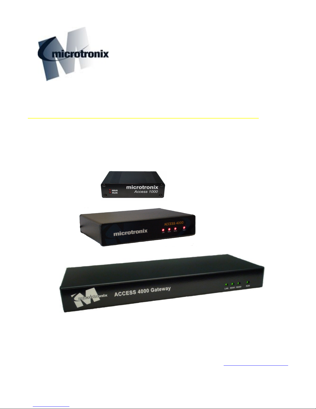
1.2 Hardware Features and Interfaces
1.2.1 Model 1000-S04 and 1000-N04
● -48VDC connector for Central Office (CO) installation
● S04 includes 100-240VAC adapter, N04 includes -48VDC cable
● 10/100 Base-T Ethernet - RJ45
● WAN (console) interface - DB25F RS530[A] configurable for RS232/V.24, X.21, V.35, RS449/V.36
● USB Host Port interface - for additional serial interfaces or storage device
● Rack-mountable using 19” or 25” shelf
1.2.2 Model 4002-S04 and 4002-N04
● -48VDC connector for Central Office (CO) installation
● S04 includes 100-240VAC adapter, N04 includes -48VDC cable
● 10/100 Base-T Ethernet – RJ45
● 2 - WAN interfaces - DB25F RS530[A] configurable for RS232/V.24, X.21, V.35, RS449/V.36
● USB Host Port interface for additional serial interfaces or storage device
● Rack-mountable using 19” or 25” shelf
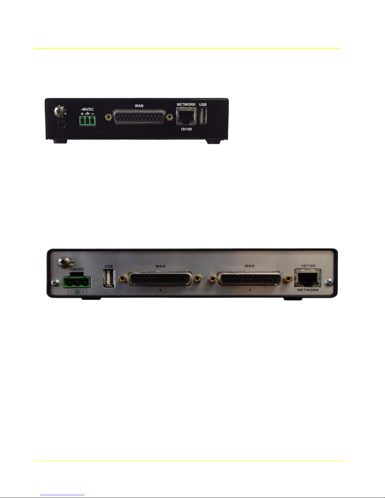
1.2.3 Model 4002-N04-RM
● 19” 1U rack mount enclosure (25” rack extension available)
● -48VDC connector for Central Office (CO) installation
● 10/100 Base-T Ethernet – RJ45
● 2 WAN interfaces - DB25F RS530[A] configurable for RS232/V.24, X.21, V.35, RS449/V.36
● Internally-mounted USB Host port interface for internal flash drive or 4 port serial expansion
9
Page 10

Microtronix Access User Guide
1.2.4 Model 4002-N44-RM
● 19” 1U rack mount enclosure (25” rack extension available)
● -48VDC connector for Central Office (CO) installation
● 10/100 Base-T Ethernet – RJ45
● 2 WAN interfaces - DB25F RS530[A] configurable for RS232/V.24, X.21, V.35, RS449/V.36
● 4 Serial ports – DB9M RS232 (internally mounted USB serial adapter)
1.3 Software/Application Features
1.3.1 System Configuration and Management
● Web-based interface accessible through any Internet browser
● Context-sensitive help on all web pages
● Command line interface available on WAN or Serial ports; ssh or telnet interfaces
● Syslog with optional remote syslog and/or storage on remote file server
1.3.2 Redundancy
● Redundancy on a pair of units using IP takeover
● Primary with redundant backup unit
● Co-redundancy between a pair of active units
● Redundancy may use primary or secondary/virtual IP addresses
1.3.3 Terminal Server
● Asynchronous Serial interface to TCP/IP
● Client or server support
● Configurable speed, parity, stop bits, and flow control method
● 1, 2, 4, or 8 additional ports on USB-attached serial adapter (optional)
1.3.4 Synchronous Server
● Synchronous HDLC interface to TCP/IP or UDP/IP
● Cient or server support
● Configurable speed, internal or external clocking
● Configurable Encoding (NRZ/NRZI)
● Configurable CRC checking and generation (16 bit, 32 bit)
● Unumbered Information (UI) header recognition and generation
10
Page 11

Microtronix Access User Guide
1.3.5 X.25
● 1024 logical channels
● SVC and PVC
● Negotiable packet sizes 16 to 4096 bytes
● Modulo-8 and 128
● DTE or DCE individually selectable at physical, data link, and packet layers
1.3.6 X.25-TCP/IP Gateway
● X.25 to TCP routing
● TCP to X.25 routing
● X.25 encapsulation using X.25 Over TCP (XOT)
● Configurable X.25-TCP conversion/encapsulation methods or RAW
1.3.7 X.25 Packet Switching
● Switching calls between local ports (using local XOT connections)
● Switching calls between remote units using XOT
1.3.8 MWI Gateway
● SIP to SMDI MWI Conversion
● SMDI to SIP MWI Conversions
● MWI Routing by DN
1.3.9 CDR Collection Manager
● Collects CDR and other files from Central Office switches
● Multiple file streams
● Client (pull) and server supported
● Supports X.25, serial, synchronous/HDLC/LAPB, and IP switch interfaces
● File distribution via FTP or SFTP/IP
11
Page 12
Microtronix Access User Guide
2 Installation
The first step that should be taken is to ensure that you have received all the equipment ordered and
that it has not been damaged in transit. If there are any external signs of damage, note them in writing
and contact the transport company to make a claim.
2.1 Packing List
Unless pre-arranged, the following are the lists of the standard items that are packed and shipped with
each model:
2.1.1 Model 1000-S04
Qty Part Number Part Description
1 1000-S04 Access 1000 Gateway unit with -48VDC input connector
1 5883-PSC30U-48 100-240VAC adapter
1 Country-specific AC power cord (NA, EU)
1 [284-MC1MF DB9F-DB25M Console cable
1 811-W6002-06 RJ45 Ethernet patch cable (blue), 6 ft
2.1.2 Model 1000-N04
Qty Part Number Part Description
1 1000-N04 Access 1000 Gateway unit with -48VDC input connector
1 W1000 -48VDC Power cord
1 [284-MC1MF DB9F-DB25M Console cable
1 811-W6002-06 RJ45 Ethernet patch cable (blue), 6 ft
2.1.3 Model 4002-S04
Qty Part Number Part Description
1 4002-S04 Access 4000 Gateway unit with 12VDC input connector
1 589-PS-1213AP 120/240VAC adapter
1 Country-specific AC power cord (NA, EU)
1 [284-MC1MF DB9F-DB25M Console cable
1 811-W6002-06 RJ45 Ethernet patch cable (blue), 6 ft
12
Page 13
Microtronix Access User Guide
2.1.4 Model 4002-N04
Qty Part Number Part Description
1 4002-N04 Access 4000 Gateway unit with -48VDC input connector
1 W4002 -48VDC Power cord
1 [284-MC1MF DB9F-DB25M Console cable, 6 ft
1 811-W6002-06 RJ45 Ethernet patch cable (blue), 6 ft
2.1.5 Model 4002-N04-RM
Qty Part Number Part Description
1 4002-N04-RM Access 4000 Gateway 19” 1U rack mount enclosure with -48VDC connector
1 W4002 -48VDC Power cord
1 [284-MC1MF DB9F-DB25M Console cable, 6 ft
1 811-W6002-06 RJ45 Ethernet patch cable (blue), 6 ft
2.1.6 Model 4002-N44-RM
Qty Part Number Part Description
1 4002-N44-RM
Access 4000 Gateway 19” 1U rack mount enclosure with 4 Serial ports and
-48VDC connector
1 W4002 -48VDC Power cord
1 [284-MC1MF DB9F-DB25M Console cable, 6 ft
1 811-W6002-06 RJ45 Ethernet patch cable (blue), 6 ft
2.1.7 Optional items
In addition to the above standard items, one of more of the following may be ordered:
● Additional WAN or serial cables
● 19” 1U rack mount shelf for holding 1, 2, or 3 Access 1000 units
● 19” 1U rack mount shelf for holding 1 or 2 Access 4000 units
● 19” to 25” rack mount adapter kit
● External USB serial adapter: 1, 2, 4, or 8 ports
● Internally mounted 4-port USB serial adapter for model 4002-N04-RM
● USB 8GB or 32GB flash drive (standard with CDR Collection Manager)
● -48VDC to 100-240VAC adapter
13
Page 14

Microtronix Access User Guide
2.2 Location
Select a location for the Access Gateway that meets the following requirements:
● Is within cabling distance of the network equipment and power connections.
● Complies with the Environment and Electrical Requirements outlined in this section.
● Does not have restricted airflow. There must be at least 2 inches clearance on all sides so that
proper air ventilation is not obstructed. If space is at a premium, you may place light equipment,
such as the network modem, on top of the unit.
● Permits access to the back of the unit to allow user to make cable connections.
2.3 Mounting
The Access Gateway may be placed on any flat surface or shelf provided that the unit is within 3 feet of
an AC power source. At least 2” of space on each side of the unit is required to ensure proper air flow.
The physical dimensions (D x W x H) and nominal weight of the Access Gateways are:
● Model 1000 – 3.34“ x 5.625“ x 1.25”, 0.5 lb (.0.22 kg)
● Model 4002 – 5.5” x 7.25” x 1.6” (14 x 18.5 x 4 cm), 1.4 lb (0.64 kg).
● Model 4002-RM – 5.4” x 14” x 1.72”, 4 lb
● Model 4002-RM – 5.4” x 14” x 1.72”, 4 lb
2.4 Electrostatic Considerations
All microcomputers are sensitive to electrostatic discharges (ESD). A direct ESD discharge to the
chassis or cables can disrupt unit operation, induce a latent failure condition, or even permanently
damage circuit components. For these reasons, you must use good ESD control procedures that
electrically ground you when making direct physical contact with the unit or cables. The use of
grounding wrist straps and cords is strongly recommended for controlling discharges and preventing
ESD damage.
WARNING:
To prevent damage to port drivers and receivers, you must use proper electrostatic control
precautions when attaching or handling cables.
2.5 Environmental Specifications
The environmental specifications recommended for maximum reliability of the Access Gateway are:
Ambient Temperature 5 to 40 degrees C (For short term operation to 45 degrees C)
Temperature rate of change 3 degrees / hour
Humidity 10% to 95% (non-condensing)
Humidity rate of change 2% / hour
14
Page 15

2.6 Power Requirements
The Access Gateway operates from a -48VDC power source.
The maximum power dissipation is listed below.
Microtronix Access User Guide
Operating Voltage
Current Draw (maximum) 125 mA 350 mA
Power 6 Watts 17 Watts
BTU 21 BTU / hour 58 BTU / hour
Fuse 1 Amp 1 Amp
Access 1000
-48 VDC
Access 4000
-48 VDC
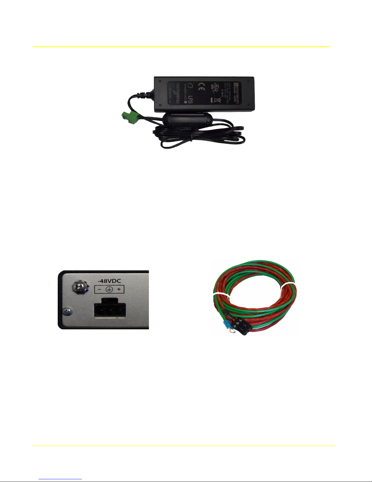
2.6.1 -48VDC Electrical Connection
The Access 1000 and 4000 with the -48VDC option are designed to operate from an approved -48VDC
Secondary Extra-low Voltage (SELV) commercial battery backed power source used in TELCO Central
Office (CO) applications. A 3-pin male power connector – suitably labeled – is provided on the rear of
the unit for connecting the -48VDC power source. The unit is protected against reverse polarity
connection of the -48VDC power source. The 48VDC power connection should be protected with a
2A, 50VDC fuse or circuit breaker.
A flame retardant wire harness with a 3-pin female jack is provided for making the -48VDC power
connection. Three #22 AWG wires in the harness provide the DC power: red +, black -, and one green
wire provides the chassis ground connection.
The Frame Ground screw connection on the rear panel must be used in order to comply with
installation requirements. This #8-32 machine screw has two external toothed (star) lock washers to
secure the unit rear plate Frame Ground connection to the Central Office GND system.
The terminal lug of the green wire ground wire must be placed between the star washers to assure an
adequate connection. A #14 AWG or larger copper wire must be used; its length should be minimized
to assure effectiveness for controlling ESD and EMI.
The Access 1000 wire harness (part number W1000) has an On Shore Technology # OSTTJ0331530
(Digi-Key # ED287-ND) 3-position female jack.
Model 1000-Nxx -48VDC power connector and W1000 wire harness
15
Page 16
Microtronix Access User Guide
The Access 1000 and 4000 may also operate from an AC power source using the safety and agency
approved (CSA/UL etc.) external 100-240 VAC switching power supply.
Model 1000-Sxx -48VDC AC power supply
The Access 4000 wire harness (part number W4002) has a Molex # 39860-0703 (Digi-Key # WM5855ND) female jack.
Figure 3: Model 4002-Nxx -48VDC power connector and W4002 wire harness
16
Page 17

Microtronix Access User Guide
3 Initial Start-up Procedure
The first step in the initial setup is to configure the IP address and network parameters. This may be
accomplished through the serial console port, or using a web browser from a PC on a reachable
Ethernet network.
Obtain the following information from your network administrator:
● IP address to be assigned to the Access Gateway
● subnet mask
● address of the default gateway
● Domain Name Server (DNS)
3.1 Configuring IP from the Ethernet port
The IP address can be configured using a standard Internet browser from a PC. The default IP address
of the Access Gateway is 10.1.1.240. The procedure is:
1) Configure a PC's Ethernet/LAN to have an IP Address on the same subnet, for example:
10.1.1.200, subnet mask 255.255.255.0
2) Connect an Ethernet patch cable between the PC and the unit, or connect to a common hub.
3) Connect power cord to the Access Gateway unit
4) Open an Internet browser on the PC to navigate to http://10.1.1.240.
5) Login with username “admin” and password “admin”.
6) Select the Ethernet option from the menu in the left pane of the main screen.
7) Configure the desired IP address and network parameters as outlined in the Ethernet section.
8) Remove the cable from the PC and connect to the network.
9) Restore the PC's previous IP settings.
3.2 Configuring Default IP from the Console port
WAN port 0 on the Access 1000 and WAN port 1 on the Access 4000 also serve as console ports
during boot-up after power is applied. There is a 10 second window that interrupts the boot process to
allow configuration using the console port.
To configure default IP network values in the bootup environment:
1) Connect the Console Cable (DB25M-DB9F) between a PC COM port and the console port of the
Access Gateway. A USB serial adapter will be required on the PC if it does not have a serial COM
port.
2) Start a terminal emulator like putty or HyperTerminal on the PC and select the correct COM port.
3) Set the COM port for: 9600 bits per second, 8 data bits, no parity, 1 stop bit, no flow control.
4) Connect power cord to apply power to the Access Gateway unit. Startup messages will appear
followed by the message: “Autoboot in 10 seconds (Enter password to stop)…”
5) Before the 10 second timer expires, type the password “foad”. (The “A4K:>” prompt will be
displayed). Retype from the beginning if an error is made.
17
Page 18

Microtronix Access User Guide
6) Enter the following commands replacing the example values with those provided by your network
administrator:
set ipaddr 10.1.1.240
set netmask 255.255.255.0
set gatewayip 10.1.1.1
7) (optional) Enter a new host name:
set hostname NEWNAME
8) Enter the following commands to save the changes and restart the system.
save
boot
3.3 Emergency IP Address Recovery
The u-boot console may be used to recover a forgotten IP address. While in the U-Boot console mode, the
default IP address and other parameters may be displayed:
print ipaddr
print netmask
print gatewayip
If the default values are not in current effect, they may override the system-defined values temporarily by setting
new default values (if desired) and entering the U-Boot commands:
set ipaddr 10.1.1.240
set netmask 255.255.255.0
set gatewayip 10.1.1.1
set runlevel 2
save
boot
When the system starts up, it will be using the default IP address information, and should be reachable on that
network. Browse into the web interface and access the Ethernet page to view the “forgotten” values. Restart the
system to get the U-Boot console, and reset run level:
set runlevel
save
boot
The system will restart with the system-defined values.
18
Page 19
Microtronix Access User Guide
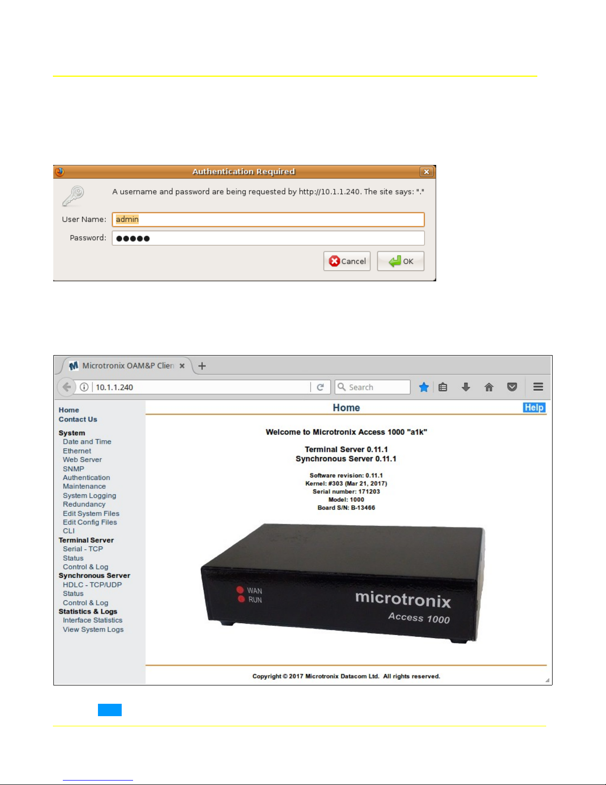
3.4 Web Configuration Interface
To access the web-based configuration interface, use an Internet browser to navigate to the IP address
of the gateway (default 10.1.1.240). When the authentication pop-up appears, use the default
username “admin” and password “admin” to log on.
Click OK, and the Home page will be displayed with the main menu down the left side. The page will
reflect model, hostname, version, and installed applications.
Click the Help button for a general configuration guide, and to download full documentation manuals.
19
Page 20
Microtronix Access User Guide
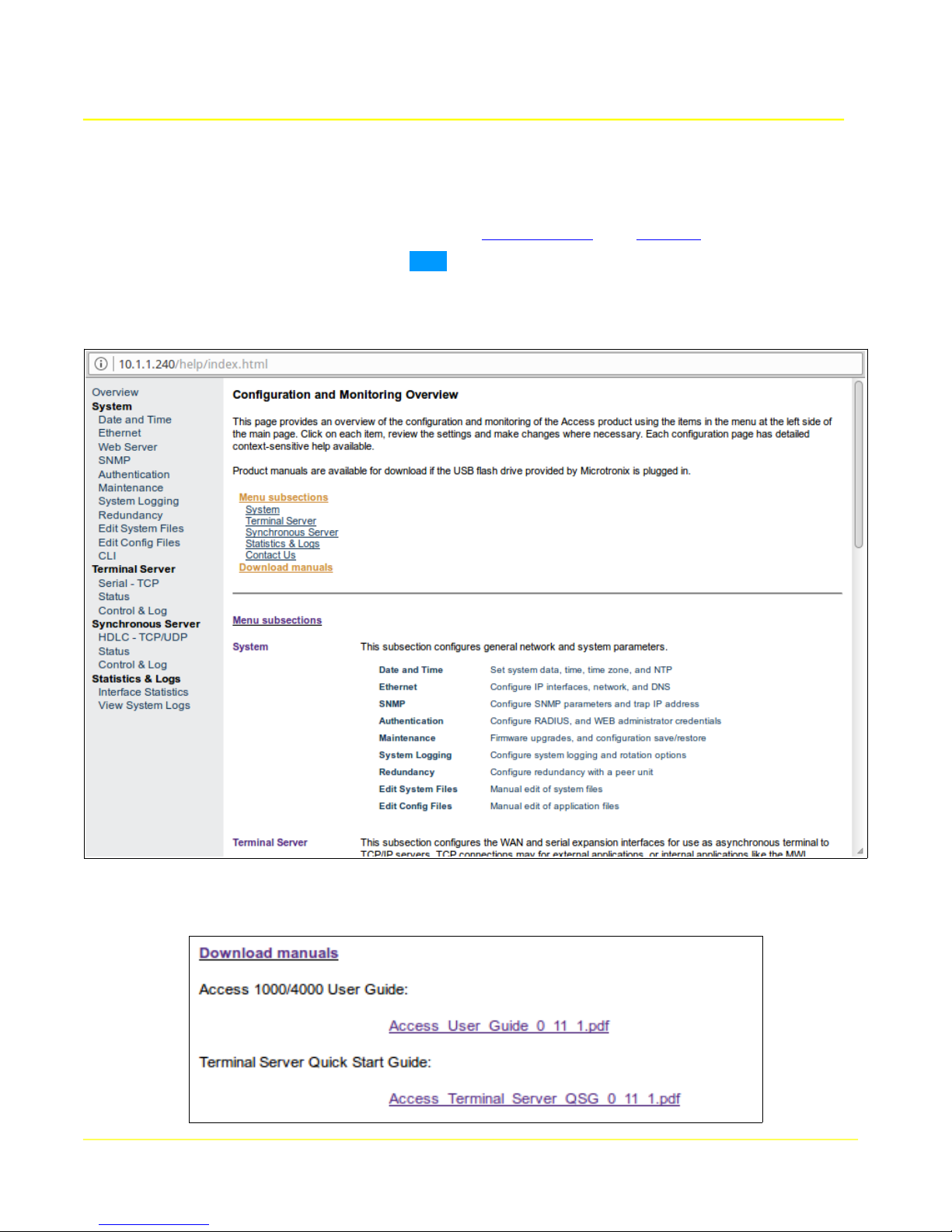
Using the main menu in the left hand pane of the displayed page, click the desired configuration or
display options. Edit as needed and remember to click any Apply or Update button to save changes.
Under the System section of the main page menu, Date and Time settings can be used to configure
date, time, time zone, and NTP server. The IP network settings are available with the Ethernet menu
item. Refer to the following sections for more detail: Date and Time, and Ethernet.
Context-sensitive help is available with the Help button located in the top right of each page. These
contain the most up-to-date information, and should be used in preference to this manual. An overview
is available from the help button on the main page:
If there is a Microtronix USB flash drive installed in the unit, the manuals (including this one) are
available by following the Download manuals link in Menu subsections:
20
Page 21

Microtronix Access User Guide
3.5 Configuring a Terminal Server
To set up a port for asynchronous / serial use, click on the Serial - TCP item in the Terminal Server
section of the main menu to display the configuration form. Configure the interface parameters to
match the attached device, and assign the TCP/IP network parameters to be connected to this
interface. Click on the Status item in the same section of the main menu to check the interface
operation.
Refer to the Terminal Server sections: Serial - TCP item for configuration details, the Status item for
details on the status display, and the Control and Log item for details of that display.
3.6 Configuring a Synchronous Server
To set up a port for synchronous / HDLC use, click on the HDLC – TCP/UDP item in the Synchronous
Server section of the main menu to display the configuration form. Configure the interface parameters
to match the attached device, and assign the TCP/IP network parameters to be connected to this
interface. Click on the Status item in the same section of the main menu to check the interface
operation.
Refer to the Synchronous Server sections: HDLC -TCP/UDP item for configuration details, the Status
item for details on the status display, and the Control and Log item for details of that display.
3.7 Configuring the X.25/TCP Gateway
To set up a port for X.25 use, click on the HDLC Physical Layer, LAPB Link Layer, and X.25 Packet
Layer items in the X.25 WAN section of the main menu to display the configuration form for each layer
of the protocol. Configure the parameters to match the attached device. Refer to the X.25 WAN
section for configuration details: X.25 Packet Layer , LAPB Link Layer, and HDLC Physical Layer.
Click on the Status item of the X.25 WAN section to display the operational status of the X.25
interfaces, and LCI Status to display the operational status of any active logical channels. Refer to the
X.25 Status section for details on the display of X.25 interfaces, and LCI Status for details on the
display of logical channels.
To configure the X.25 to TCP/IP socket interconnections, click on the X.25 to TCP Routes item in the
X.25 Gateway section of the main menu to display the configuration form. Add or modify routing
entries to map incoming X.25 connections to outbound TCP connections.
To configure the TCP to X.25 mapping / routing, click on the TCP to X.25 Routes item in the X.25
Gateway section of the main menu to display the configuration form. Add or edit routing entries to map
incoming TCP connections to outbound X.25 connections.
Click on the Connection Status item of the X.25 Gateway section to display the operational status of
any active X.25–TCP connections.
Refer to the X.25 Gateway sections for configuration details: TCP to X.25 Routes, and X.25 to TCP
Routes, the Connection Status item for details on the status display of X.25-TCP connections, and the
Control and Log item for detail on that display.
3.8 Configuring the SIP/SMDI MWI Gateway
To configure the MWI Gateway, click on the MWI Gateway MWI Gateway items.
21
Page 22

Microtronix Access User Guide
To configure a VoIP voice messaging (UMS or VMS) server as a source for SIP Notify MWI messages,
click on UMS SIP Interface. To configure a legacy VMS as a source for SMDI MWI messages, click on
VMS Interface.
To configure the MWI output to legacy switch SMDI links, or to VoIP PBX's, click on Switch Interfaces.
3.9 Configuring the CDR Collection Manager
To configure the CDR Collection Manager, refer to the CDR Collection Manager manual.
22
Page 23
Microtronix Access User Guide
4 System Configuration
This section allows general configuration and administration of the system. Click on each item in the
System section of the main menu to display and modify system parameters.
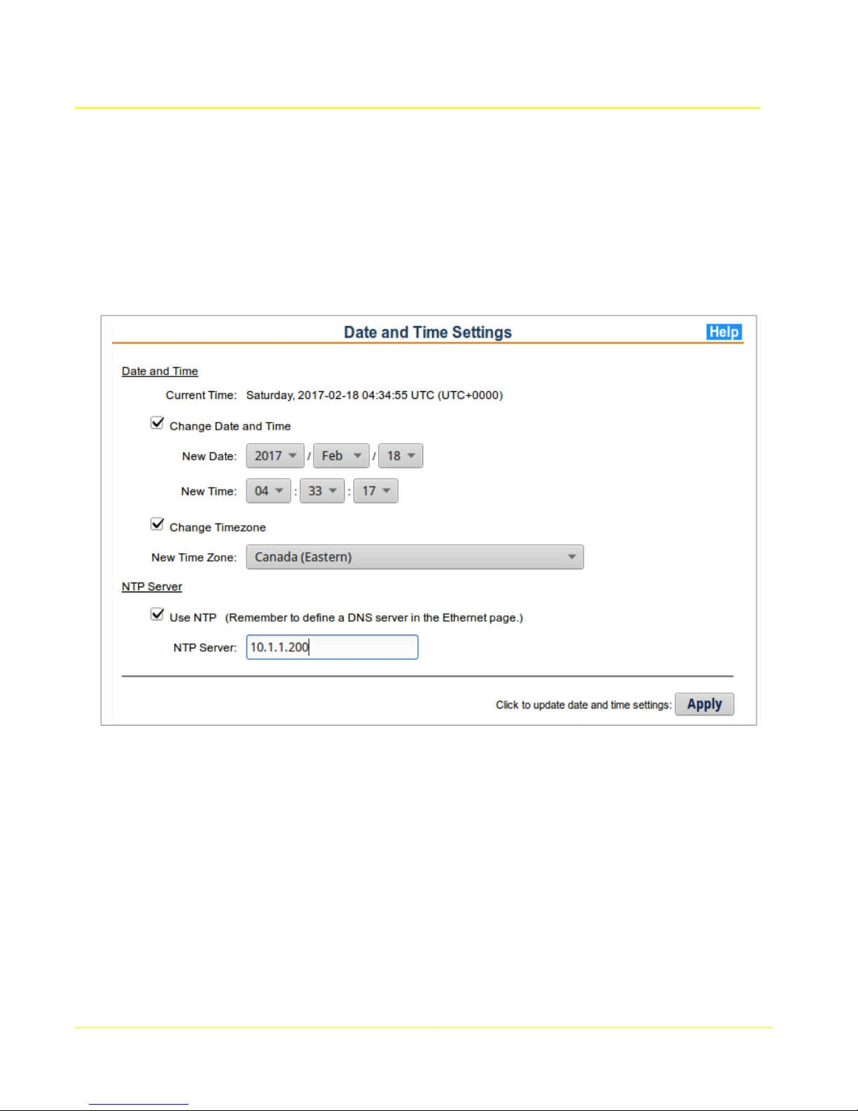
4.1 Date and Time
The Date and Time page displays the current time and date for the time zone configured. Time, date,
and time zone may be changed. For synchronized time, an NTP server should be configured.
4.1.1 Date and Time Setup
To modify the date, time of day, and time zone, select the relevant Change box and use the drop down
menus to select the correct values.
4.1.2 NTP Server
To use an NTP (Network Time Protocol) server to synchronize the correct time, select the Use NTP
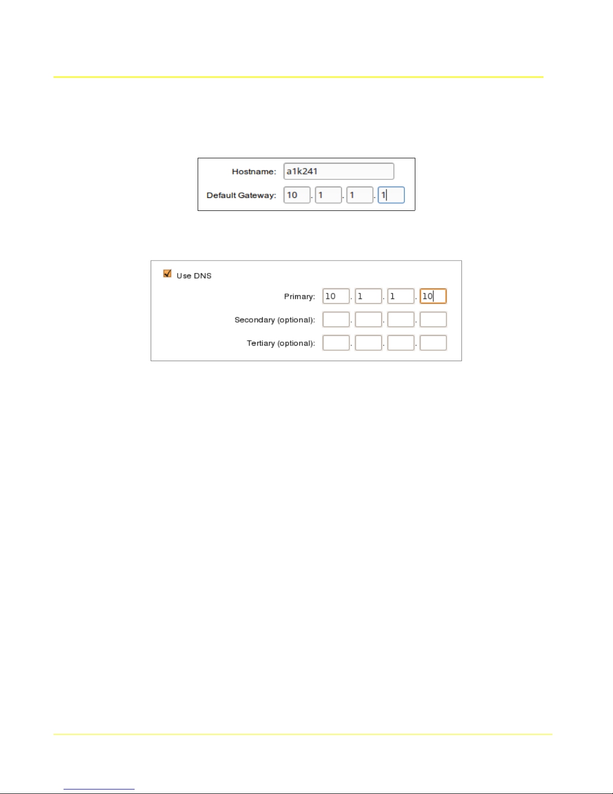
box, and enter the desired NTP server address. A DNS server will need to be configured in the
Ethernet Configuration section if a domain name is used.
To apply changes, click the Apply button. Changes will take effect immediately.
23
Page 24
Microtronix Access User Guide
4.2 Ethernet
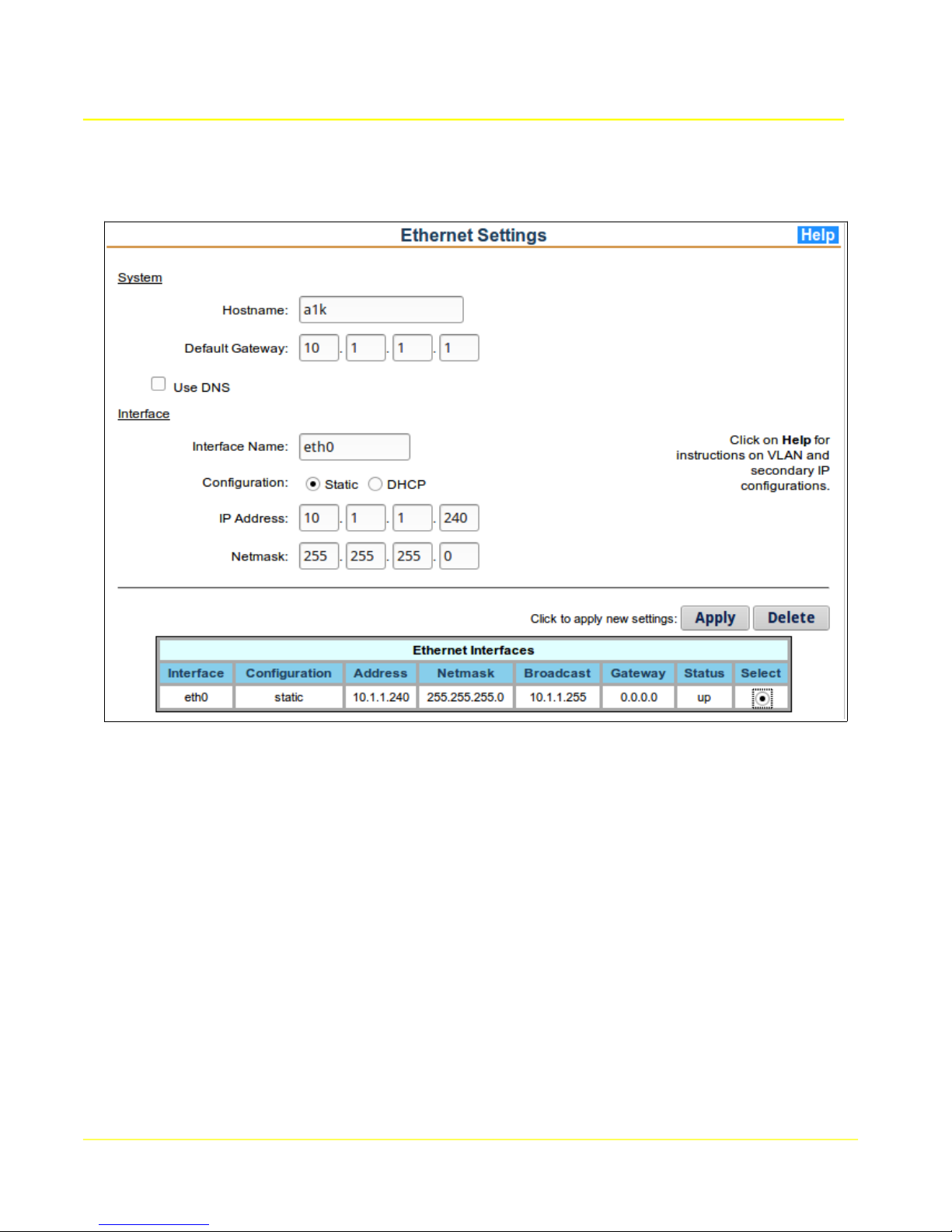
The Ethernet page displays the status of the current interfaces configured. The form allows changes to
the interfaces and the addition of VLAN interfaces.
4.2.1 Network Setup
To modify the IP network settings, fill in the provided configuration fields. If the desired interface has
previously been configured, the interface may be selected from the Ethernet Interfaces table which will
populate the fields with its current settings.
To configure a VLAN interface, enter “eth0.x” in the “Interface Name” field, where ‘x’ is an integer from 0
to 255.
To configure a secondary IP address, enter “eth0:x” in the “Interface Name” field, where ‘x’ is an integer
from 0 to 255.
To delete a previously configured interface, enter “0.0.0.0” as the IP address for the interface before
clicking the Apply button.
To apply changes, click the Apply button. Only the interface corresponding to the Interface Name field
will be updated.
Note: Upon updating the primary Ethernet adapter configuration, the web interface will automatically
redirect the browser to its updated location, if reachable.
24
Page 25
4.2.2 System Parameters
Hostname: The host name assigned to the Access Gateway.
Default Gateway: The IP address of the default gateway which provides access to external
networks.
Use DNS: To specify DNS servers for domain name resolution, check the “Use DNS” box and
enter the desired addresses in the provided fields. Up to three servers can be specified.
Microtronix Access User Guide
4.2.3 Interface Parameters
Network interfaces may be modified and added. The “eth0” interface refers to the Ethernet 10/100 port.
VLAN interfaces may be added to “eth0”.
Interface Name: The label assigned by Linux to the Ethernet adapter. The default primary
Ethernet adapter is labelled “eth0”, secondary IP labels appear as “eth0:x, and VLAN labels
appear as “eth0.x” where x is an integer from 0 to 255
Configuration: To specify a static IP address for the interface, select “Static”. To have a DHCP
server assign IP network settings automatically, select “DHCP”. When the DHCP option is
selected, the following parameters are disabled.
IP Address: The IP address used for web interface access and route connections.
Netmask: The subnet mask which specifies the gateway's network accessibility.
Gateway: The IP address of the gateway on this subnet. This field is not used for defining
the default gateway – see System Parameters above.
25
Page 26
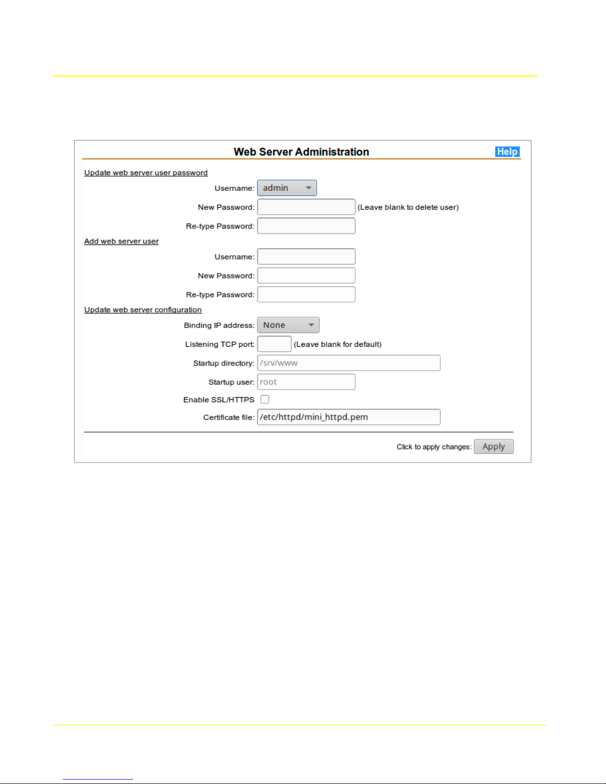
4.3 Web Server
Microtronix Access User Guide
4.3.1 Update web server user password
Select a name from the drop-down list of configured web users, then enter a password to be used for
authentication for the selected user. Enter the new password a second time for validation.
4.3.2 Add web server user
Enter a new web user name in the Username field, then enter a password to be used for authentication
for the user. Enter the new password a second time for validation.
4.3.3 Update web server configuration
4.3.3.1 Web Server Parameters
Binding IP address: Choose the local IP interface to which the TCP listening port should be
bound to prevent unauthorized external access from other IP interfaces. If 127.0.0.1 is selected,
then a secure ssh tunnels should be defined to allow specific clients to connect using public key
authentication.
Listening TCP port: Enter the TCP port number that should be used for the web werver. Port
80 is assumed if non-secore HTTP is configured, and 443 if SSL/HTTPS is enabled.
26
Page 27

Microtronix Access User Guide
Startup directory: Enter the directory where web pages reside. This is fixed at “/srv/www/” on
the Access 1000/4000.
Startup user: Enter the user name under which the web server should operate. This is fixed as
“root” on the Access 1000/4000.
Enable SSL/HTTPS: Click the button to select secure HTTPS operation.
Certificate file: Enter path and name of the certificate file to be used for HTTPS. The default is
shown in the form above.
27
Page 28
Microtronix Access User Guide
4.4 SNMP
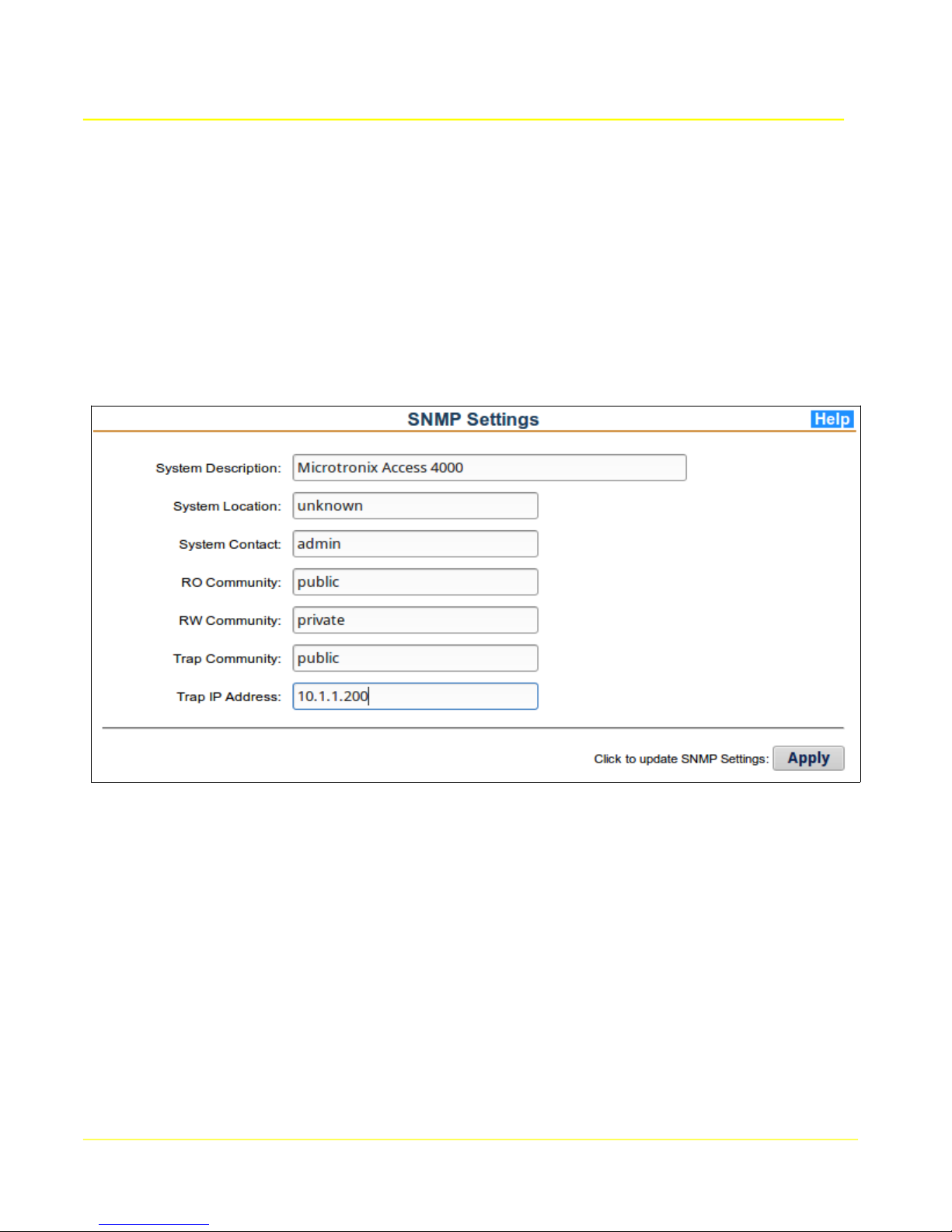
An SNMP agent is enabled by default in the Access Gateway, and will respond to requests if polled.
The RO Community name must match that used by the the remote SNMP client. The client may
change the system parameters, in which case the RW Community name must also match.
If the Trap IP Address is defined, then system startup and interface alarms will be delivered to the
SNMP management server at that address. The Trap Community name must be changed to that
expected by the server.
The SNMP parameters may be modified using the form and clicking the Apply button. Changes will
take immediate effect.
4.4.1 SNMP Parameters
System Description: A string describing the system name.
System Location: A string describing the system location.
System Contact: A string describing the system contact information.
RO Community: A string describing the community for read-only access.
RW Community: A string describing the community for read-write access.
Trap Community: A string describing the community for traps.
Trap IP Address: The address of the SNMP server listening for traps.
28
Page 29
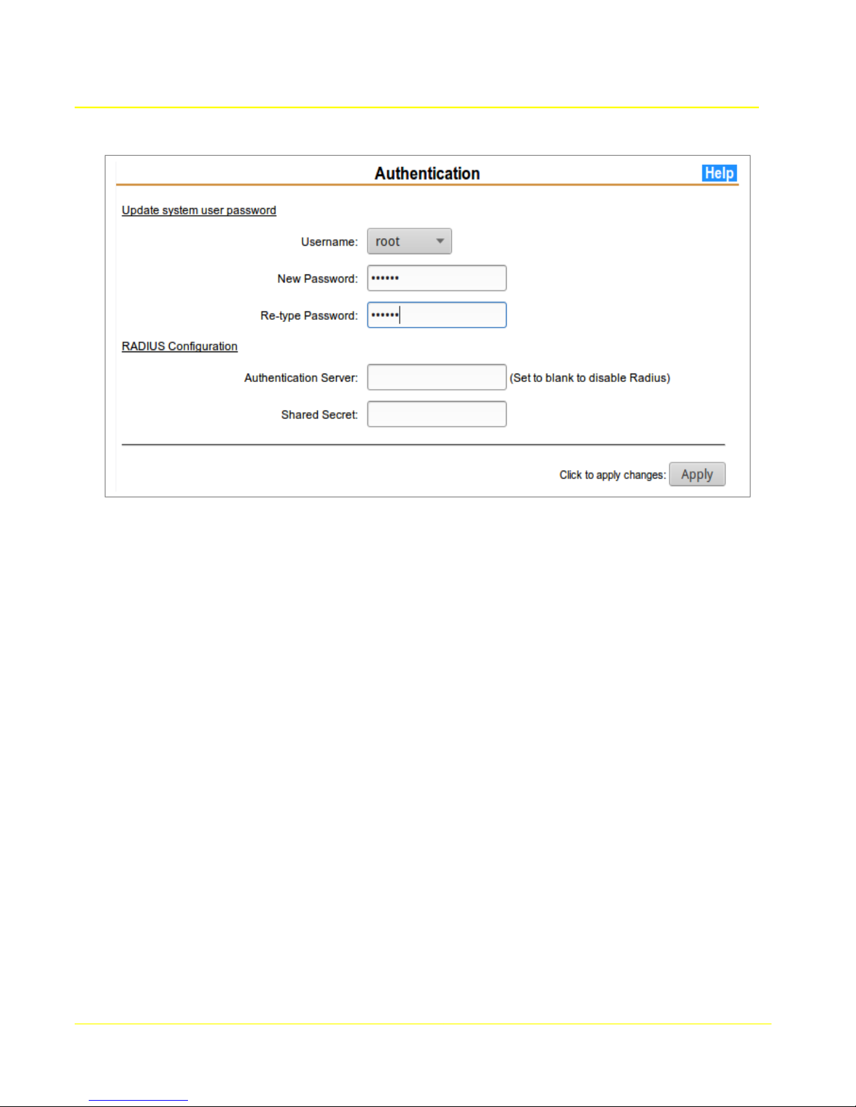
4.5 Authentication
Microtronix Access User Guide
4.5.1 Update system user password
4.5.1.1 Sytsem user Parameters
Username: Select from {root, admin}.
New Password: Enter a password to be used for authentication for the selected user.
New Password (re-enter): Enter the new password a second time for validation.
4.5.2 RADIUS Authentication
To enable authentication through a RADIUS server, select the “Use RADIUS for Authentication” box,
and enter the RADIUS server parameters in the provided fields.
4.5.2.1 RADIUS Parameters
Authentication Server: Enter the server address. To avoid a DNS query it is recommended
that an IP address is used instead of a hostname.
Shared Secret: Enter the shared secret that the RADIUS server will use to validate and encrypt
communication between the client and the server. Whitespace characters in the shared secret
are not supported by the RADIUS client.
29
Page 30
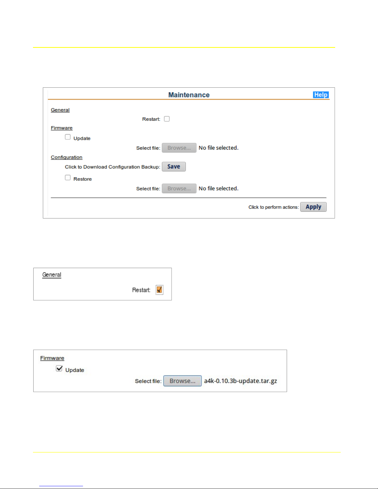
4.6 Maintenance
Microtronix Access User Guide
4.6.1 General
To reboot the Access Gateway, select the Restart box and click Apply. If other maintenance actions
are selected on this page, they will be performed prior to rebooting.
4.6.2 Firmware
To update the firmware (flash image) on the Access Gateway, select the Update box and fill in the
relevant fields.
4.6.2.1 Update Firmware
Select file: To upload a firmware update file, click Update, then click the “Browse...” button to
select the file to upload. The update will occur after the Apply button is clicked.
30
Page 31

Microtronix Access User Guide
4.6.3 Configuration
Configuration settings can be downloaded for backup, and then later restored to the Access Gateway.
To download the configuration settings backup file, click the Save button, and choose a location when
prompted. The proper filename for the file is “etc.tar.gz”. If the file or filename is altered by some
mechanism then it may not be useable to restore the configuration at a later date.
To upload a previously downloaded backup, click the Restore checkbox and choose the file using the
File field.
File: Select a previously downloaded configuration backup file to restore the configuration
settings. The file must be named “etc.tar.gz” and be a gzipped tar file for the upload to succeed.
31
Page 32

4.7 System Logging
Microtronix Access User Guide
This page allows access to the configuration of the sytem logging interface and log file rotation. Log
files are rotated by the log rotation script scheduled to run just before midnight local time. The current
log file is zipped and saved on the root file system (/var/backups/) or on any mounted USB flash drive
(/mnt/usb1/log/).
4.7.1 Remote logger IP address
To send logs to a remote syslog server, enter the IP address of the server in this field. The remote
syslog server must be able to accept remote syslogs. The default port is UDP 514, but this can be
modified by appending “:<port#> to the IP address.
If this field is changed, the syslog daemon will be restarted when the Update button is clicked
4.7.2 Rotation age
Enter the number of days that log files will be retained. Files older than this age will be deleted. If files
are being saved to the root file system, keep this value as short as possible to prevent the limited space
from being filled. Files may be transferred to a file server (see below).
4.7.3 Remote File server
Rotated log files may be saved to a remote file server. Enter the server's IP address, the transfer
method (FTP, SFTP, or SCP), and the account credentials. SFTP and SCP will require that the local
authentication key file be copied to the remote file server.
32
Page 33

4.8 Redundancy
Microtronix Access User Guide
This page allows configuration of redundancy between a pair of Access units. One may be master, the
other slave, or they can be set up for co-redundancy.
Redundancy is accomplished by monitoring an IP address assigned to the peer unit. If that IP address
does not respond for any reason, the monitoring unit will assume it as its own secondary IP address.
In general, it is best for the monitered IP address to be a secondary IP address definition in the
monitored unit. This secondary IP address will be used for applications like X.25/TCP gateway, and the
primary used for configuration and management. It would be counter-productive for a unit to take over
anothers primary IP and “masquerade” its configuration and management interface.
4.8.1 Remote peer IP address
This is the IP address of the remote peer unit, preferably defined as a secondary IP address in the peer
unit. The secondary IP address in the peer unit is defined in the Ethernet page using Interface name
“eth0:0”.
4.8.2 Secondary IP address interface name
If the Remote peer IP address is taken over, it will be temporarily defined as a secondary IP address
using this interface name. If takeover has occurred, the temporary definition will appear in the table in
the Ethernet page.
4.8.3 ARP timeout
This is the number of seconds to wait for an arping response from the peer. If it expires without
response the peer, the IP takeover will occur.
33
Page 34

Microtronix Access User Guide
4.8.4 Enable local X.25 interface watchdog
The local redundancy daemon will bring down the secondary IP address as defined by “eth0:0” if the
local X.25 ports go down, and back up if the X.25 ports resume.
4.8.5 Poll interval
This is the number of seconds between arping poll attempts. The shorter this is, the sooner a takeover
can occur when there is a failure in the peer unit.
34
Page 35
Microtronix Access User Guide
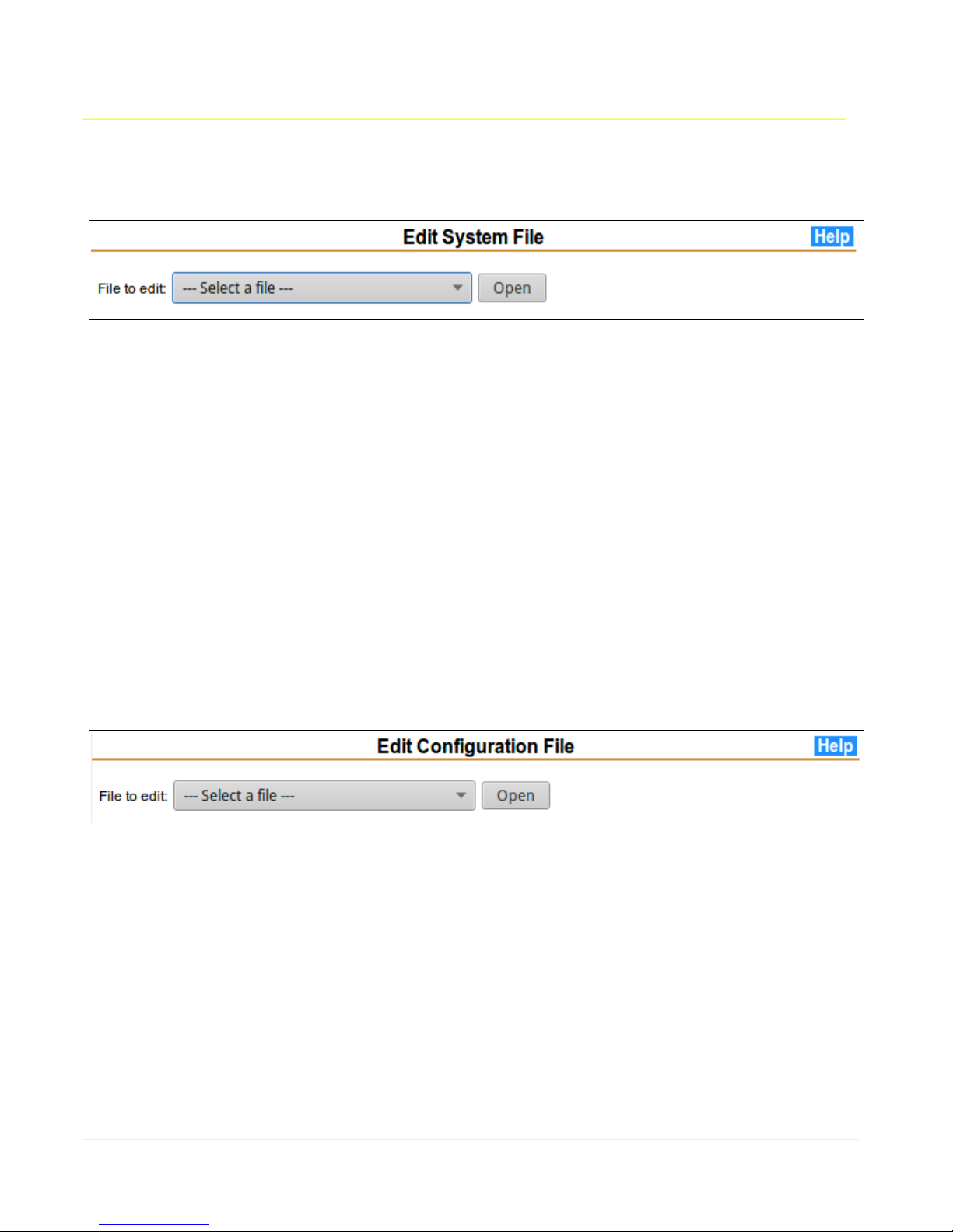
4.9 Edit System Files
This page allows access to system files for advanced settings. This should only be used by
experienced Linux users or with the explicit guidance of a Microtronix support technician. The Help
page provides more details.
Some of the things that may be accomplished are:
● Enable or disable servers like telnet, ssh, httpd, https, etc
● Enable system console on the Console/WAN port or a USB serial adapter port
● Enable NFS file system
● Modify USB file system for non-DOS USB flash drives
● Enable redundancy with a peer unit
● Operating system hardening
Contact Microtronix support with your requested change for instructions on how to accomplish it.
4.10 Edit Config Files
This page allows access to application configuration files for advanced settings. This should only be
used by experienced users or with the explicit guidance of a Microtronix support technician. The Help
page provides more details.
Some of the things that may be accomplished are:
● Modify X.25 interface parameters
● Modify Terminal Server parameters
● Modify Synchronous Server parameters
Saved changes will not take effect until the relevant interface is restarted.
Contact Microtronix support with your requested change for instructions on how to accomplish it.
35
Page 36
Microtronix Access User Guide
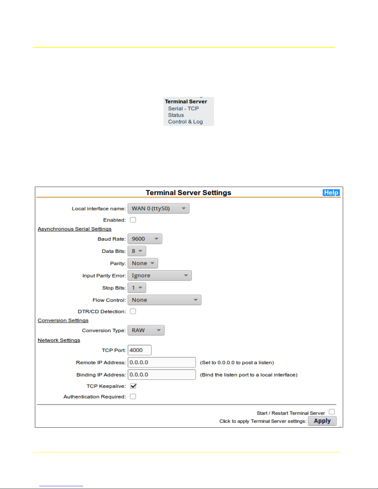
5 Terminal Server Configuration
This section allows configuration and administration of the serial to TCP/IP interfaces. Click on each
item in the Terminal Server section of the main menu to invoke the configuration form and status
displays.
5.1 Serial - TCP
The terminal server application provides a raw TCP socket connection to an asynchronous serial device
attached to a local serial interface, through a specified TCP port.
36
Page 37

Microtronix Access User Guide
5.1.1 Terminal Server Setup
To configure the terminal server application, select the desired interface from the Local interface name
field, set the relevant communication parameters, and click the Apply button.
Note: The Start/Restart Terminal Server box must be selected in order to have configuration changes
applied immediately, otherwise only the configuration will be saved.
5.1.2 Terminal Server Parameters
Parameters must be set to match those of the attached device.
5.1.2.1 Serial Interface Settings
Local interface name: The physical interface to which the terminal server application will attach
(internal name).
WAN 0 (ttyS0) - WAN 0 (hdlc0) MUST be disabled in the X.25 and Synchronous pages
WAN 1 (ttyS1) - WAN 1 (hdlc1) MUST be disabled in the X.25 and Synchronous pages
Serial port 1 (ttyUSB0)
Serial port 2 (ttyUSB1)
Serial port 3 (ttyUSB2)
Serial port 4 (ttyUSB3)
Enabled: Select this box to enable the terminal server application for the selected interface.
Baud Rate: The rate in bits per second at which characters are transmitted. This field has a
range from 300 to 115200.
Data Bits: The number of data bits per character. This field ranges from 5 to 8.
Stop Bits: The minimum period of time between characters, in bit-time (so at 9600 baud and 1
stop bit, the delay between characters is at least 1/9600 seconds). If 1.5 is selected, then an
actual stop bit value of 2 will be used, as true 1.5 stop bits is not supported.
Parity: An additional bit that can be used for error detection. If enabled, it is added to the end of
each character. Options are:
None No parity bit will be added.
Even A parity bit will be added so that the character has an even number of 1's.
Odd A parity bit will be added so that the character has an odd number of 1's.
Flow Control: The method of controlling data flow to the attached device. Options are:
None No flow control method will be used.
XON/XOFF XON/XOFF characters will be used to resume and suspend.
RTS/CTS The status of the RTS and CTS signals will determine whether or not
data is transmitted.
DTR/CD Detection: Select this box to have the terminal server react to changes on the
received DTR or CD modem control signal. The DB25F WAN interfaces have a DCE interface,
so the received signal is DTR. The DB9M Serial ports are DTE, so the received signal is CD. If
enabled, TCP connections will only occur when this signal is raised.
37
Page 38

5.1.2.2 Conversion Settings
Conversion Type: Specify the method of passing data between the TCP socket and the serial
interface.
RAW: Data is passed transparently as received (byte stream).
LINE: Data from the serial interface is passed transparently to the TCP socket. Data
from TCP is forwarded when a CR is received. LF following CR is stripped.
IAC-ESC: Data from the TCP socket is scanned for Telnet commands which are stripped
and ignored. Escaped IAC characters have the escape removed. Data from the
interface is scanned for IAC characters, and an IAC escape is inserted. This ensures
binary data integrity in the data stream.
5.1.2.3 Network Settings
Authentication Required: If this option is enabled, a login session is initiated upon incoming
connections from a TCP/IP client. If RADIUS support is enabled, the RADIUS server is queried
for authentication.
TCP Port: If the IP Address is set to 0.0.0.0, the terminal server will accept connections from a
remote TCP/IP client on this TCP port number. If the IP Address is set to a valid destination, the
terminal server will connect to a remote TCP/IP server at the Specified TCP port number.
Remote IP Address: If the Remote IP address is set to 0.0.0.0, then the terminal server will
listen on the specified TCP Port for connections from a remote TCP/IP client. If the IP address
is set to a valid destination, then the terminal server will initiate a connection to a remote TCP/IP
server.
Microtronix Access User Guide
Binding IP Address: If the Remote IP address is set to listen (0.0.0.0), then the terminal server
will bind the specified TCP Port to a local interface.
5.2 Status
This page provides status information for serial interfaces configured for asynchronous operation.
The table below shows that a connection from a remote TCP client/server has been established.
The values in the status display are provided by the running application, and may not necessarily reflect
the configured values. If they do not match, then the Terminal Server may need to be restarted.
38
Page 39

Microtronix Access User Guide
39
Page 40

Microtronix Access User Guide
The following table provides the description of each column.
Terminal Server Status
Interface Local interfaces that are currently being used for terminal server operation. Note
that the direction of modem signals is reversed between DCE and DTE devices.
WAN 0 - ttyS0 (DCE)
WAN 1 - ttyS1 (DCE)
Serial 1 - ttyUSB0 (DTE)
Serial 2 - ttyUSB1 (DTE)
--etc--
Baud Speed of the interface.
Bits Number of bits per data character.
Parity Parity bit.
Stop Number of stop bits.
F/C Flow Control method.
DSR Status of the Data Set Ready modem signal. ON indicates readiness of the DCE
device to accept connections.
CD Status of the (Data) Carrier Detect modem control signal. ON indicates data
connection status.
CTS Status of the Clear To Send modem signal. Reflects the DCE flow control condition if
hardware flow control option has been selected.
DTR Status of the Data Terminal Ready modem signal. ON indicates the DTE device is
ready for a connection
RTS Status of the Request To Send modem signal. Reflects the DTE flow control
condition if hardware flow control option has been selected.
Conversion Method used for data conversion between the serial port and the TCP/IP socket.
Local IP IP address of the local TCP socket. No socket if reported as 0.0.0.0
Local TCP TCP port number of the local TCP socket. If the local IP address is 0.0.0.0, indicates
the terminal server is listening on that port
Remote IP If not 0.0.0.0, indicates the IP address of a remote client/server.
Remote TCP If not 0, indicates the TCP port number of a remote client/server.
40
Page 41

Microtronix Access User Guide
5.3 Control and Log
This page provides status and control of terminal server application. System log messages pertinent to
this application will be displayed.
The current status of the applications are indicated by a Running or Stopped indicator. Stopping or
restarting an application will disconnect any active sessions and the associated TCP and serial
communication sockets will be closed.
If the application is stopped, then a Start button will be displayed to start it again. A terminal server
must be enabled (from the Terminal Server Configuration pages) in order to be started.
The system log scrolling region shows significant application events since the box was started. If there
are any unusual errors, they will be shown in the log.
41
Page 42
Microtronix Access User Guide
6 Synchronous Server Configuration
This section allows configuration and administration of the synchronous interfaces. Click on each item
in the Synchronous Server section of the main menu to invoke the configuration form and status
display.
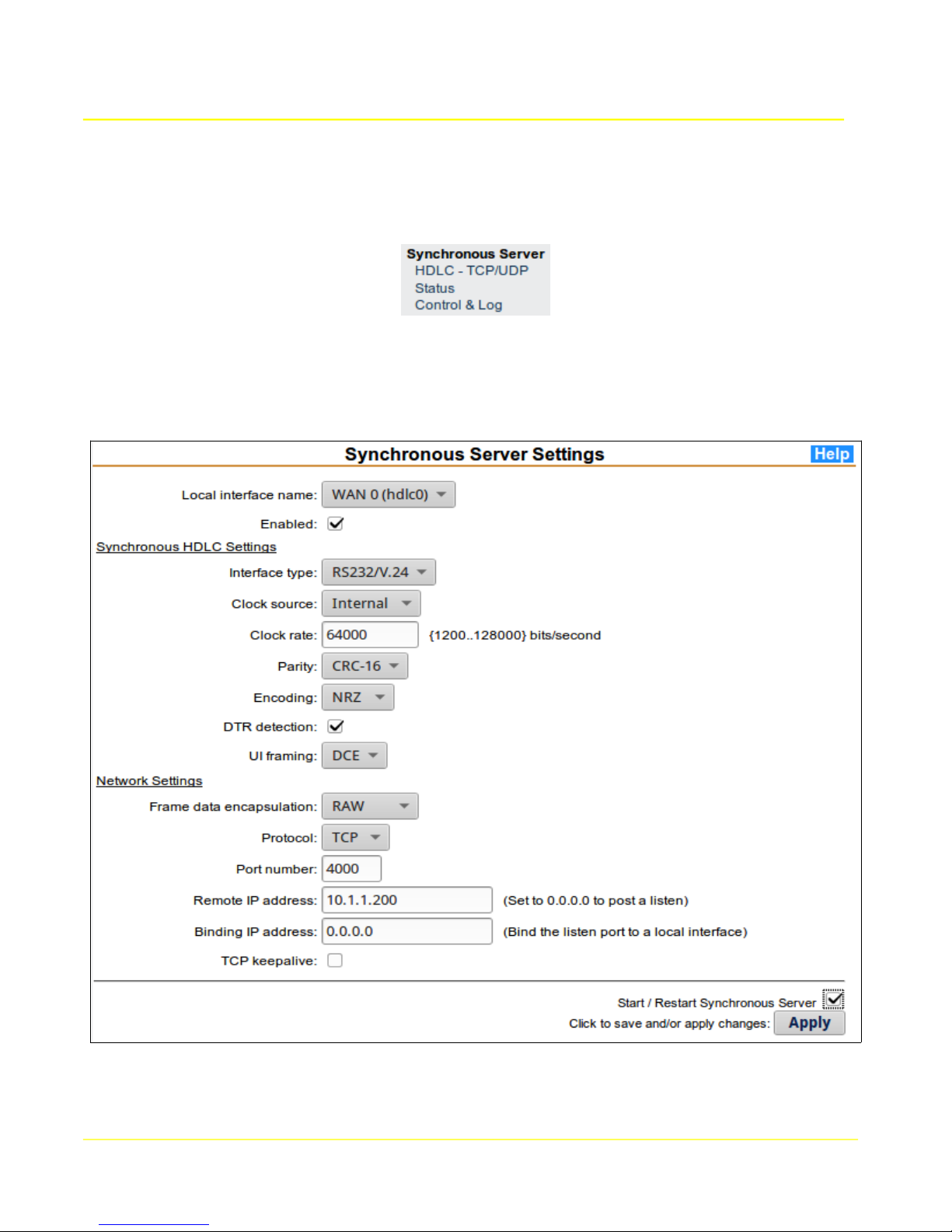
6.1 HDLC – TCP/UDP
The synchronous server application provides a TCP or UDP socket connection to a synchronous/HDLC
device attached to a local interface.
42
Page 43

Microtronix Access User Guide
6.1.1 Synchronous Server Setup
To configure the synchronous server application, select the desired interface from the Local interface
name field, set the relevant communication parameters, and click the Apply button.
Note: The Start/Restart Synchronous Server box must be selected in order to have configuration
changes applied immediately, otherwise only the configuration will be saved.
43
Page 44

Microtronix Access User Guide
6.1.2 Synchronous Settings
Parameters must be set to match those of the attached device.
Local interface name: The local physical interface to which the synchronous server application will
attach.
- WAN 0 (hdlc0)
- WAN 1 (hdlc1)
Note: when using WAN port 0 (hdlc0), then WAN 0 MUST be disabled in the X.25 WAN, and
Terminal Server pages. Similarly for WAN 1.
Enabled: Select this box to enable the synchronous server application for the selected interface.
Interface type: The physical interface type to be used. The supported types are: RS232/V.24, V.35,
X.21, RS449/V.36, RS530, and RS530a. Refer to the Cables and Connectors section to determine the
appropriate cable for the application.
Clock source: Specifies the source of the synchronous clocking (timing) signal.
If connecting to a DCE device (like a modem) that provides the clock signal, an external clock source is
chosen. For independent transmit and receive clocks, choose External. For a single clock signal
source, choose RxFromTx. When using a tail circuit cable, choose TxFromRx.
If the interface is to provide clocking signal to a DTE device, then select an internal source and specify
a Clock Rate appropriate for the interface. Choose Internal for independent receive and transmit
clocks, or DTE to derive the clock from the DTE’s external transmit clock.
Clock rate: Specifies the clock rate used for the internal clock source (Internal, TxFromRx, TxInt). Do
not set the speed higher than the attached device’s capability. RS232 is limited to 128Kb/s with a short,
reliable cable. Otherwise RS232 is limited to 64Kb/s. Other interface types allow speeds up to 10
Mbps.
Parity: Cyclical Redundancy Checksum (CRC) added to the end of trnasmitted frames for the detection
of bits errors by the receiver. If enabled, it is added to the end of each frame, and checked on received
frames. Options are:
None No CRC will be generated or checked.
CRC-16 2-byte CRC as per ITU
CRC-32 4-byte CRC as per ITU
Encoding: The method of bit encoding. Options are:
NRZ Non-Return-to-Zero
NRZI Non-Return-to-Zero-Inverted
DTR detection: Select this box to have the Access Gateway react to changes on the received DTR
modem control signal. If enabled, TCP connections will only occur when the DTR signal is raised.
UI framing: Enables HDLC Unnumbered Information (UI) frame header recognition and generation.
Options are:
No Feature disabled (data passed to/from frames as-is)
DCE UI headers are checked/stripped, and generated using address 01
DTE UI headers are checked/stripped, and generated using address 01
44
Page 45

Microtronix Access User Guide
6.1.3 Network Settings
Frame encapsulation: Specify the method of passing frames across a TCP socket. If UDP is selected,
encapsulation is not likely to be necessary (set to RAW).
Valid values are:
RAW: TCP data is passed transparently as received (byte stream). Received frames may
become split across TCP packets, or merged into single TCP packets, and the frame
boundaries are lost. UDP sockets do not have this issue.
MBIT: Received frames are prefixed with a 2 byte header containing the length of the frame
when sent across the TCP/IP interface, so that the boundaries of the frame can be
reconstructed by the remote TCP receiver. No checking is done, so invalid headers can cause
data loss and stalling.
RFC1006: Received frames are prefixed with a 4 byte header containing a prefix and the length
of the frame when sent across the TCP/IP interface, so that the boundaries of the frame can be
reconstructed by the remote TCP receiver. Header checking is performed, and any errors will
cause any active connection to be terminated.
Protocol: Select the type of IP socket connection to be created with the remote host, connectionoriented TCP or connectionless UDP. Note that TCP guarantees data delivery, whereas UDP does not.
UDP can be used in a broadcast application.
Port number: If the remote IP Address is set to 0.0.0.0, the sync server will accept connections from a
remote TCP/IP client on this TCP port number. If the IP Address is set to a valid destination, the sync
server will connect to a remote host at the specified TCP or UDP port number.
Remote IP address: If the remote IP address is set to 0.0.0.0, then the sync server will listen on the
specified TCP Port for connections from a remote TCP/IP client., otherwise the sync server will
establish a TCP or UDP connection from a remote client/server.
Binding IP address: This specifies the IP address of a local interface, like 127.0.0.1, to which the TCP
or UDP socket will be bound. If set to local, connections can only occur locally.
45
Page 46
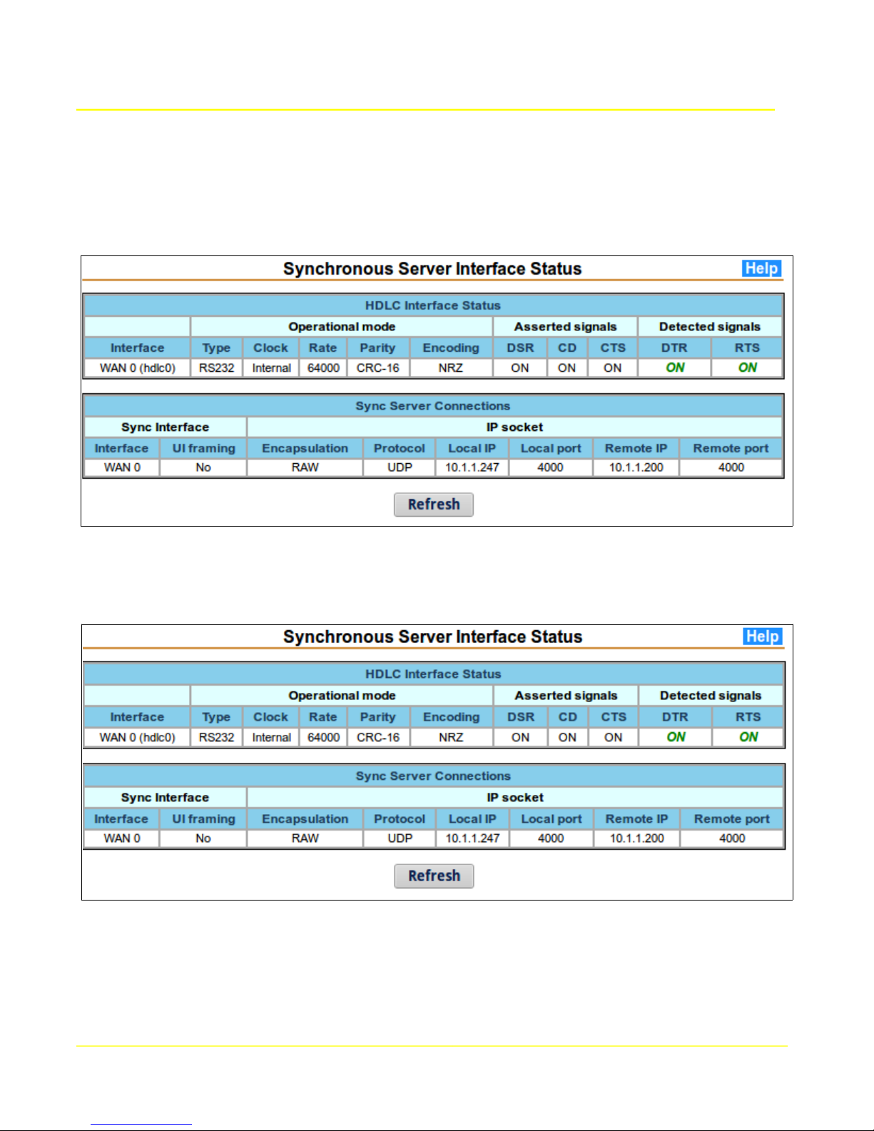
Microtronix Access User Guide
6.2 Status
This page provides status information for serial interfaces configured for synchronous/HDLC operation.
This table shows that a connection with a remote TCP client/server has been established.
This table shows that a connection with a remote UDP client/server has been established. Note that
the local and remote UDP port numbers are always the same.
The values in the status display are provided by the running application, and may not necessarily reflect
the configured values. If they do not match, then the Synchronous Server may need to be restarted.
46
Page 47

Microtronix Access User Guide
The following table provides the description of each column.
Interface Local interface(s) that are currently being used for synchronous server operation.
Type Interface type.
Clock Clock source.
Rate Clock rate. If an external clock source, will display “unknown”.
Parity Bit encoding.
Encoding CRC generation/detection or none.
DSR ON when the Sync Server application is running
CD When ON, indicates the presence of a TCP connection
CTS ON when a TCP connection is present.
DTR ON indicates the connected device is ready for a connection
RTS ON indicates the connected device is ready for data.
UI framing Indicates whether UI framing is check/generated on the HDLC interface
Encapsulation Indicates the encapsulation (or none) of frame data over the TCP socket
Protocol Indicates the type of IP socket, TCP or UDP
Local IP Local IP address of the socket. No socket if reported as 0.0.0.0
Local port Port number of the local TCP or UDP socket. If the local IP address is 0.0.0.0,
indicates the sync server is listening on that port
Remote IP If not 0.0.0.0, indicates the IP address of a remote client/server.
Remote port If not 0, indicates the TCP or UDP port number of a remote client/server.
47
Page 48

Microtronix Access User Guide
6.3 Control and Log
This page provides status and control of synchronous server application. System log messages
pertinent to this application will be displayed.
The current status of the applications are indicated by a Running or Stopped indicator. Stopping or
restarting an application will disconnect any active sessions and the associated TCP and HDLC
communication sockets will be closed.
If the application is stopped, then a Start button will be displayed to start it again. The synchronous
server must be enabled (from the Synchronous Server Configuration pages) in order to be started.
The system log scrolling region shows significant application events since the box was started. If there
are any unusual errors, they will be shown in the log.
48
Page 49

Microtronix Access User Guide
7 X.25 WAN Interfaces Configuration
This section allows for configuration and administration of the WAN (Wide Area Network) interfaces for
X.25. Click on each item in the X.25 WAN section of the main menu to invoke the configuration forms
and status displays.
7.1 HDLC Physical Layer
This form allows any of the X.25 physical layer parameters to be set. The interface type MUST match
the attached equipment, and the clock source MUST be compatible. If an internal clock source is
selected, the clock rate must not exceed the attached peer's capability.
7.1.1 Physical Layer (HDLC) Setup
1. Choose the Local Interface name column for the WAN interface to configure.
2. Modify the parameters to be compatible with the attached device.
3. In order for the configuration to take effect, the Restart WAN interface box must be checked.
Otherwise the configuration will be saved, but will not take effect until the next time the interface is
restarted.
4. Click the Update button to save changes, and restart the interface if selected.
49
Page 50

7.1.2 HDLC Parameters
Local interface name: The X.25 WAN interface being configured. This will be WAN 0 (hdlc0),
or WAN 1 (hdlc1).
Interface Type: The physical interface type to be used. The supported types are: RS232/V.24,
V.35, X.21, RS449/V.36, RS530, and RS530a. Refer to the Cables and Connectors section to
determine the appropriate cable for the application.
Clock Source: Specifies the source of the synchronous clocking (timing) signal.
If connecting to a DCE device (like a modem) that provides the clock signal, an external clock
source is chosen. For independent transmit and receive clocks, choose External. For a single
clock signal source, choose RxFromTx. When using a tail circuit cable, choose TxFromRx.
If the interface is to provide clocking signal to a DTE device, then select an internal source and
specify a Clock Rate appropriate for the interface. Choose Internal for independent receive and
transmit clocks, or DTE to derive the clock from the DTE’s external transmit clock.
Clock Rate: Specifies the clock rate used for the internal clock source (Internal, TxFromRx,
TxInt). Do not set the speed higher than the attached device’s capability. RS232 is limited to
128Kb/s with a short, reliable cable. Otherwise RS232 is limited to 64Kb/s. Other interface
types allow speeds up to 10 Mbps.
DTR Detection: If the attached device does not support a DTR signal, then disable the
detection (assumed readiness). Otherwise, enable it for detection of the device’s readiness to
communicate.
Microtronix Access User Guide
Enable: Check to enable HDLC/X.25 operation. Un-check o prevent the port from
communicating using HDLC/X.25. HDLC must be disabled before the port can be available for
terminal or synchronous server configuration.
50
Page 51

Microtronix Access User Guide
7.2 LAPB Link Layer
The LAPB Link Layer configuration page allows any of the X.25 data link layer 2 parameters to be set.
The values that MUST match to the attached X.25 equipment are the default window size and modulus.
The Emulation mode (DTE/DCE) MUST be set to the opposite of the attached peer. Other parameters
are not usually changed, but can be modified to fine-tune an interface.
7.2.1 LAPB Setup
1. Choose the Local Interface name column for the WAN interface to configure.
2. Modify the parameters to be compatible with the attached device.
3. In order for the configuration to take effect, the Restart WAN interface box must be checked.
Otherwise the saved configuration not take effect until the next time the interface is restarted.
4. Click the Update button to save changes, and restart the interface if selected.
7.2.2 LAPB Parameters
Local Interface name: The X.25 WAN Interface being configured. This will be WAN 0 (hdlc0),
or WAN 1 (hdlc1). WAN 1 is only present on the Access 4000.
Mode: The emulation mode may be specified as Data Connecting Equipment (DCE) or Data
Terminating Equipment (DTE). This MUST be opposite to the attached peer device.
Link Setup Start: This configures the first mode setting frame that will be sent (or passive
operation) when the link is starting up. SABM is the usual default, but other settings may be
used to resolve compatibility issues with the peer device.
51
Page 52

Microtronix Access User Guide
Window Modulus: LAPB may be set to standard (Modulo-8) or extended (Modulo-128)
sequencing. Modulo-8 allows for up to 7 unacknowledged packets to be transmitted before
receiving an acknowledgment. Modulo-128 will allow up to 127 packets to be transmitted before
receiving an acknowledgment. This MUST match the peer device. The usual default is Modulo-
8.
Window Size (K): The maximum number of unacknowledged frames that may be transmitted.
This MUST match the peer device. For Modulo-8, the valid values are 1-7, for modulo-128, 1-
127. The usual default is 7.
Maximum Information Frame Size (N1 Count): The maximum number of bits (expressed as
bytes) in an Information (I) frame that the port is willing to accept. This value should include the
following:
● maximum data packet size desired (minimum 128 bytes, maximum 4096)
● packet header (3 bytes for modulo-8, or 4 bytes for modulo-128)
● frame header (2 bytes for modulo-8, or 3 bytes for modulo-128)
● checksum (2 bytes)
Retransmit Attempts (N2 Counter): The maximum number of attempts made to complete the
successful transmission of a frame before attempting recovery.
Retransmit Timeout (T1 Timer): The period of time which must pass before a retransmission
of an unacknowledged frame may occur. The normal default is 3 seconds, but this may be
increased for slower links (less than 4800 baud) to avoid unnecessary retransmissions.
Acknowledgment Hold Back Timeout (T2 Timer): The period of time, in seconds, before an
acknowledgment is transmitted. This allows outbound information (I) frames to “piggyback” any
outstanding acknowledgments thereby canceling the timer. This should always be less than the
attached peer's T1 timer.
52
Page 53

Microtronix Access User Guide
7.3 X.25 Packet Layer
The X.25 configuration page allows any of the X.25 packet layer parameters to be set. The values that
MUST match to the attached peer are the packet & window default sizes, and the number of SVC &
PVC. The Emulation mode (DTE/DCE) is usually set to the opposite of the attached peer, but this is not
mandatory. Other parameters are not usually changed, but can be modified to fine-tune an interface.
7.3.1 X.25 Packet Layer Setup
1. Choose the Local Interface name column for the WAN interface to configure.
2. Modify the parameters to be compatible with the attached device.
53
Page 54

Microtronix Access User Guide
3. In order for the configuration to take effect, the Restart WAN interface box must be checked.
Otherwise the configuration will be saved, but will not take effect until the next time the interface is
restarted.
4. Click the Update button to save changes, and restart the interface if selected.
7.3.2 X.25 Parameters
Local interface name: The X.25 WAN Interface being configured. This will be WAN 0 (hdlc0),
or WAN 1 (hdlc1). WAN 1 is only present on the Access 4000.
Emulation Mode: The emulation mode may be configured as Data Circuit Equipment (DCE) or
Data Terminating Equipment (DTE) for normal X.25 operation.
In DTE mode, outbound calls choose the highest available logical channel number, and
outbound clear/reset/restart packets will contain DTE cause codes (0, 128-255).
In DCE mode, outbound calls choose the lowest available logical channel number, and
outbound clear/reset/restart packets may contain DCE cause codes (1-127). Normally this is
opposite to the peer device, but may be set to DCE for DCE behavior regardless of the peer
setting.
Choosing RAW disables X.25 packet layer processing and allows LAPB I-frames to pass
transparently through the interface.
Allow Reverse Charge Calls: Specifies that the reverse charging facility will be allowed to be
present in incoming calls (the called party pays for the charges).
Allow Outgoing Flow Control Facilities: Selecting this allows any outbound X.25 call request
to contain packet or window size negotiation facilities. If not selected, negotiation will not be
sent. This may force a backwards negotiation to be initiated.
Default Packet Size: The default maximum number of data bytes to be included in a single
packet on this link. The default value may also be changed by packet size negotiation during
call setup. This MUST match the peer. The normal default is 128.
Maximum Negotiable Packet Size: The maximum packet size that may be negotiated during
call setup.
Window Modulus: X.25 may be set to standard (Modulo-8) or extended (Modulo-128)
sequencing. Modulo-8 allows for up to 7 packets to be transmitted before receiving an
acknowledgment. Modulo-128 will allow up to 127. This MUST match the peer device.
Default Window Size: The maximum number of unacknowledged packets that are allowed to
be transmitted or received. This MUST match the peer device. The normal default is 2.
Maximum Negotiable Window Size: The maximum window size that may be negotiated during
call setup.
Number of PVC: The number of Permanent Virtual Circuits for the link. This MUST match the
peer device.
Number of SVC: The number of Switched Virtual Circuits for the link. This MUST match the
peer device.
Start SVC Logical Channel: The logical channel number which will be assigned to the first
SVC. This number must be at least one (1) larger than the number of PVCs defined. This
MUST match the peer device.
54
Page 55

Microtronix Access User Guide
Acknowledgment Hold Back Timeout (T2 Timer): The length in seconds before packet
acknowledgments (RR) are sent.
Restart Request Timeout (T10/T20 Timer): The length in seconds before an outbound restart
request is retransmitted. Canceled once a restart confirmation is received.
Call Request Timeout (T11/T21 Timer): The length in seconds started when a call request is
transmitted. Canceled when a call accept or clear request is received. Upon expiry, a clear
request will be transmitted.
Reset Request Timeout (T12/T22 Timer): The length in seconds started when a reset request
is transmitted. Canceled when a reset request or reset confirm is received. Upon expiry, a clear
request (SVC) or reset request (PVC) will be transmitted.
Clear Request Timeout (T13/T23 Timer): The length in seconds, started when a clear request
is transmitted. Canceled when a clear request or clear confirm is received. Upon expiry, a
diagnostic packet will be transmitted (DCE) or a clear request will be re-transmitted (DTE).
55
Page 56
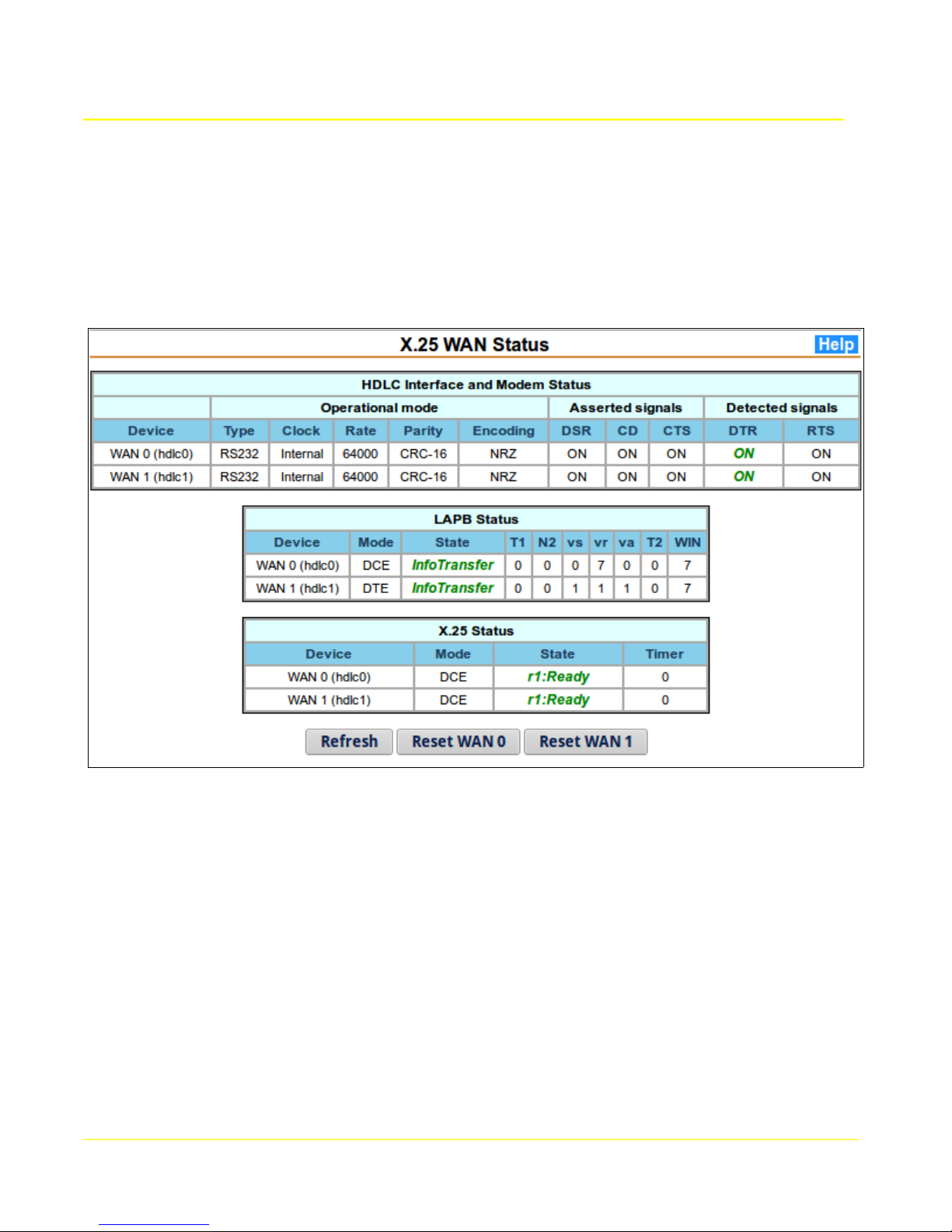
Microtronix Access User Guide
7.4 X.25 Status
The X.25 Status page displays the current status of the X.25 Interface at each of the 3 layers,
physical /HDLC, LAPB, and X.25. The operational values are those in used in current operation. Any
saved changes to the values may have not become effective yet. If this is the case, then restart the
interface.
56
Page 57

Microtronix Access User Guide
7.4.1 HDLC Interface Status
The HDLC Interface status table provides information for the physical layer. The following table
provides a description of each column.
HDLC Interface Status
Interface Interface(s) that are currently being used for sync server operation.
WAN 0 (hdlc0)
WAN 1 (hdlc1)
Type Interface type.
Clock Clock source.
Rate Clock rate. If an external clock source, will display “unknown”.
Parity Bit encoding. Always NRZ for X.25
Encoding CRC generation/detection. Always CRC-16 for X.25
DSR ON when the interface is enabled.
CD ON when the interface is enabled.
CTS ON when the interface is enabled.
DTR ON indicates the connected device is ready.
OFF indicates the device is not ready or not connected
RTS ON indicates the connected device is ready.
OFF indicates the device is not ready or not connected
57
Page 58

Microtronix Access User Guide
7.4.2 LAPB Status
The LAPB status table provides status information for the LAPB frame layer. The following table
provides a description of each column.
LAPB Status
Parameter Description
Interface Interface(s) that are currently being used for LAPB / X.25
WAN 0 (hdlc0)
WAN 1 (hdlc1)
Mode The current mode of the X.25 device:
DTE- Data Terminating Equipment (terminal emulation)
DCE – Data Connecting Equipment (network emulation)
State The current state of the LAPB device.
DM – Disconnected Mode
LinkSetup – establishing data link (SABM sent)
Info transfer – Normal data transfer
FRMR – frame recovery
T1 Remaining time in seconds before retransmission of an unacknowledged frame
N2 Current retransmit attempts - number of attempts already made to complete the
successful transmission of a frame
vs Send State Variable v(s) – next send frame sequence number
vr Receive State Variable v(r) – next expected frame sequence number
va Last acknowledged frame sequence number v(a)
T2 Remaining time in seconds before transmission of an outstanding acknowledgement
WIN The current frame window size for the interface.
58
Page 59

Microtronix Access User Guide
7.4.3 X.25 Status
The X.25 Status table provides information and state of the X.25 interfaces. The following table
provides the description of each column.
X.25 Status
Parameter Description
Interface Interface(s) that are currently being used for X.25.
WAN 0 (hdlc0)
WAN 1 (hdlc1)
Mode The current emulation mode of the X.25 packet layer:
DTE - Data Terminating Equipment (terminal emulation)
DCE -Data Connecting Equipment (network emulation)
RAW - Transparent LAPB interface – reference is LCI 1
State The current state of the X.25 device. States include:
Not Ready – lower level is down
r1: Ready – Packet Control Ready
r2 – DTE Restart Request
r3 – DCE Restart Indication
Timer The remaining time of the outstanding Restart Request Timer before retransmission.
59
Page 60

Microtronix Access User Guide
7.5 LCI Status
This page displays the current status of active X.25 Logical Channel Interfaces (LCI) on the X.25 WAN
interfaces. Logical channel 0 in Listening state means that the gateway is expecting calls to be
received on the interface.
The following table describes each column of the status table:
Parameter Description
Interface Local interface associated with the X.25 logical channel
WAN 0 (hdlc0)
WAN 1 (hdlc1)
Remote
Address
Local
Address
LCI Logical channel identifier (SVC or PVC number)
State Current state of the logical channel.
v(s) Sequence number of the next data packet to be transmitted.
X.25 to TCP/IP: address displayed here will be the Calling X.25 Address.
TCP/IP to X.25: address displayed here will be the Called X.25 Address.
PVC Connection: address displayed here will be “PVC” with the logical channel
number of the PVC
X.25 to TCP/IP: address displayed here will be the Calling X.25 Address.
TCP/IP to X.25: address displayed here will be the Called X.25 Address.
PVC Connection: address displayed here will be “PVC” with the logical channel
number of the PVC
p1 – Channel Ready or “Listening”
p2 – DTE Call Request
p3 – DCE Incoming Call
p4 – Data Transfer
d1 – Flow Control Ready
d2 – DTE Reset Request
d3 – DCE Reset Indication
p5 – Call Collision
p6 – DTE Clear Request
p7 – DCE Clear Indication
60
Page 61

Microtronix Access User Guide
v(r) Sequence number of the next data packet expected to be received
v(a) Last acknowledged sequence number
v(l) Last acknowledged sequence number
t Time remaining, in seconds, of an outstanding timer
sW Send window size
sP Send packet size
rW Receive window size
rP Receive packet size
Snd-Q Amount of data in the socket pending transmission
Rev-Q Amount of data in the socket pending processing
61
Page 62

Microtronix Access User Guide
8 X.25/TCP Gateway Configuration
This section allows general configuration and administration of the X.25 – TCP mappings used by the
X.25 Gateway application. Click on each item in the X.25 Gateway section of the main menu to
display/modify mappings, and view connection status.
8.1 TCP to X.25 Routes
When routing from TCP/IP to X.25, the TCP connection is initiated by the remote IP host using the
Listening TCP Port as the destination. The Gateway scans the routes in canonical order for the first
matching entry, and then establishes an X.25 connection with a remote X.25 host using the outbound
X.25 Connection parameters to construct the call request. When the remote X.25 host accepts the call,
the gateway between the TCP socket and X.25 logical channel is ready for data transfer.
The required parameters for a TCP/IP to X.25 route are the following:
● Listening TCP Port
62
Page 63

Microtronix Access User Guide
● TCP/IP Data Encapsulation (Conversion) Type
● Local X.25 Interface
● X.25 Connection Type (SVC or PVC)
● Called (destination) X.25 Address, or PVC Logical Channel Number
The route setup page provides a route table with all TCP/IP to X.25 route entries along with a form for
route editing.
8.1.1 Route Table
Upon loading the TCP to X.25 Routes page, the TCP to X.25 Routes table presents the current
TCP/IP to X.25 routes. The higher the route is ranked in the table the higher the priority a route will
take. As entries are added, modified and ranks adjusted, the table will change. These changes are not
finalized until the Save and Apply Changes button has been clicked.
8.1.2 Creating a New Route
Under the Inbound TCP/IP Connection section of the route edit form, enter the following:
A Listening TCP Port number to which the remote IP host will connect.
The Conversion Type to specify the message preservation or encapsulation method.
Under the Outbound X.25 Connection section of the route edit form, enter the following:
The X.25 interface upon which the remote X.25 host will be reachable.
The Connection Type, which is either a Switched Virtual Circuit (SVC) or Permanent Virtual
Circuit (PVC).
If an SVC type has been selected, enter the Called X.25 Address. If a PVC type has been
selected, enter the Logical Channel Number.
Click the Add Entry button to add the route to the route table. The new route will be added as the
lowest rank.
Use the up and down arrows to adjust the ranking of the new route. The lower the number, the higher
the priority the route will take in the scan for a match.
NOTE: Routes added to the table do not take effect until the Save and Apply Changes button has
been clicked.
8.1.3 Editing an Existing Route
In the TCP to X.25 Routes table, a route may be selected for editing by clicking the radio button
located within the Edit column of the table in the corresponding route row. Once selected, the route will
be displayed in the Route Editing form.
Within the form the routes may be modified.
In order for the route to be updated in the route table, the Update Entry button must be pressed. The
Add Entry button may also be pressed if a new route is to be created.
8.1.4 Remove an Existing Route
In the TCP to X.25 Routes table a route may be flagged for removal by selecting the checkbox
provided in the Remove column of the table in the corresponding route row. Multiple routes may be
selected.
63
Page 64

Microtronix Access User Guide
The route will not be removed until the Save and Apply Changes button has been clicked.
8.1.5 Show Facilities
Selecting Show Facilities provides additional parameters in the edit form display. This allows for
further generation of additional X.25 call facility parameters including packet and window negotiation.
8.1.6 TCP to X.25 Route Parameters
8.1.6.1 Identify inbound TCP/IP connection
Remote IP Address: IP address of the remote IP host. Used to further qualify an incoming TCP/IP
connection request.
Remote TCP Port: TCP port number of the remote IP host. Used to further qualify an incoming TCP/IP
connection request.
Binding IP Address: The IP address of the local interface to which the listening TCP port will be
bound. This field will be used as a matching criteria when finding a destination. If not specified,
connections to any local IP address will be accepted.
Listening TCP Port: TCP port number on which the gateway is listening. The remote IP host uses this
as the destination port number.
Conversion Type: Conversion type that will be used for TCP/IP data transfer, XOT, MBIT, RAW, RAWMBIT, RFC1006, Q-MBIT, RBP, QRBP, AEPN, OFTP, LINE, or IAC-ESC. The remote TCP/IP host
application must support this method. Refer to the Conversions And Encapsulations section for details
8.1.6.2 Generate outbound X.25 connection
Called Address: X.121 address inserted into the called (destination) address field of the outbound call
request. Not used for PVC.
Local Interface: Name of the physical or virtual local interface to which the peer X.25 device is
connected:
WAN 0 (hdlc0)
WAN 1 (hdlc1))
ANY (either WAN interface)
64
Page 65

Microtronix Access User Guide
XOT (X.25 Over TCP with X.25 termination).
If the peer X.25 device is attached to a remote XOT router, then select “XOT”, and specify the IP
address and TCP port number of the remote XOT peer device.
XOT remote IP address: IP Address of the remote XOT peer. Relevant only when Local interface
(above) is set to “XOT”.
XOT remote TCP port: TCP port of the remote XOT peer. The normal default is port 1998. Relevant
only when Local interface (above) is set to “XOT”.
X.25 connection type: Type of logical channel connection made to the remote X.25 host, SVC or PVC.
Calling address: The X.121 address inserted into calling (source) address field of the outbound call
request. A wildcard “?” may be entered into the address that will be replaced by the least significant
decimal digit of the remote TCP port number. Not used for PVC.
Calling address: The X.121 address inserted into called (destination) address field of the outbound
call request. Not used for PVC.
Call User Data: Specifies the userdata to be inserted into the call request. This field includes any
Protocol ID bytes (PID). Examples of PID encoding are “01:00:00:00” for PAD (X.29) calls and
“03:01:01:00” for OSI Transport Layer calls.
Protocol Handler: Specifies the handling of protocols above the X.25 packet layer 3. Currently, X.29 is
the only option available. X.29 does partial handling of X.29 messages contained in Q-bit packets, and
is only effective when Conversion Type RAW, RAW-MBIT, MBIT, RFC1006, RBP, LINE, or IAC-ESC is
selected.
Local LCN: For PVC connection type, specifies the Logical Channel Number to connect.
XOT remote LCN: For XOT conversion type, and PVC connection type: specifies the Logical Channel
Number at the X.25 interface of the remote XOT peer.
XOT remote interface: For XOT conversion type and PVC connection type: specifies the interface
name <in brackets> at the remote XOT peer. For example: <hdlc0>
Window Size: Window size negotiation which will be initiated during call setup for SVC, or the size
used for a PVC (not negotiated).
Packet Size: Packet size negotiation which will be initiated during call setup for SVC, or the size used
for a PVC (not negotiated).
Throughput Class: Data rate to be negotiated during call setup. Not used for PVC.
Reverse: Specifies that the call request is reverse charged (collect call). Not used for PVC
Fast Select: Allows the inclusion of user data in clear request packets, and allowing up to 128 bytes of
user data in call request/confirm, and clear request packets. Not used for PVC.
Calling Address Extension: DTE facility inserted into the call request facility field.
Called Address Extension: DTE facility inserted into the call request facility field.
65
Page 66

Microtronix Access User Guide
Example encoding for OSI NSAP address 36-12345678-123 (AFI-IDI-DSP) is:
“3600000012345678123F”
where the AFI is “36” for X.121 format, the IDI “12345678” is left padded with “0” to make 14 digits, and
the DSP “123” is right padded with “F” to make an even number of digits.
66
Page 67

Microtronix Access User Guide
8.2 X.25 to TCP Routes
When a call request is received from the peer X.25 host, the route table is scanned in canonical order
for the first matching entry, using the inbound X.25 connection parameters to compare to the inbound
X.25 call request. When a match is found, the outbound TCP connection parameters of the matched
route entry are used to construct the TCP connection request to the remote IP host. When the remote
IP host accepts the connection, the X.25 call will be accepted, and the gateway connection between the
TCP socket and X.25 logical channel is then ready for data transfer using the conversion method
specified in the route entry.
When a PVC route is set up, the TCP/IP connection will be automatically established before the PVC is
opened.
The required parameters for a TCP/IP to X.25 route are:
● X.25 Connection Type (SVC or PVC)
● X.25 Interface
● TCP Data Encapsulation Type
● IP Address of remote TCP/IP host
● TCP port of the remote TCP/IP host
67
Page 68

Microtronix Access User Guide
The route setup page provides a route table with all the X.25 to TCP/IP route entries along with a form
for route editing.
8.2.1 Route Table
Upon loading the X.25 to TCP Routes page, the X.25 to TCP Routes table presents the currently
defined X.25 to TCP/IP routes. The higher the route is ranked in the table, the higher the scanning
priority. As entries are added, modified and ranks adjusted, the table will change. These changes are
not finalized until the Save and Apply Changes button has been clicked.
8.2.2 Creating a New Route
1.Under the Identify inbound X.25 connection section of the route edit form, enter the following:
● Select the Local interface which is connected to the peer X.25 host
● The Connection Type, which is either Switched Virtual Circuit (SVC) or Permanent Virtual
Circuit (PVC).
● If an SVC type has been selected, a Called X.25 Address may be entered. If a PVC type
has been selected, a Logical Channel Number in the defined range must be entered.
● A Calling X.25 Address may be specified. This will be inserted into the source or calling
address field of the X.25 call request.
1.Under the Generate outbound TCP/IP connection section of the route edit form, enter the
following:
The Conversion Type for the TCP/IP connection.
The IP Address of the remote TCP/IP host.
The TCP port number that the remote TCP/IP host is listening on.
1. Click the Add Entry button to add the route to the route table. The new route will be added as
the lowest rank.
2. Use the up and down arrows to adjust the ranking of the new route. The lower the number, the
higher the priority the route will take in the scan for a match.
NOTE: routes added to the table do not take effect until the Save and Apply Changes button has been
clicked.
8.2.3 Editing an Existing Route
1. In the X.25 to TCP Routes table, a route may be selected for editing by clicking the radio button
located within the Edit column of the table in the corresponding route row. Once selected, the route
will be loaded into the Route Editing form.
2. Within the form, the route may be modified.
3. In order for the route to be updated in the route table, the Update Entry button must be pressed.
The Add Entry button may also be pressed if a new route is to be created using an existing route
as a template.
68
Page 69

Microtronix Access User Guide
8.2.4 Remove an Existing Route
1. In the X.25 to TCP Routes table a route may be flagged for removal by selecting the checkbox
provided in the Remove column of the table in the corresponding route row. Multiple routes may be
selected.
2. The route will not be removed until the Save and Apply Changes button has been clicked.
8.2.5 X.25 to TCP Route Parameters
8.2.5.1 Identify inbound X.25 connection
Local interface: Name of the X.25 physical or virtual interface to which the peer X.25 client is
connected (WAN 0, WAN 1, ANY, XOT).
If the peer X.25 device is attached to a remote XOT router, then select “XOT”, and specify the listening
TCP port number in XOT listen TCP port field below.
XOT bind IP address: IP Address of a local IP interface to restrict access.
XOT listen TCP port: The listening TCP port to which a remote XOT peer will connect. The
normal default is port 1998.
X.25 connection type: Type of connection being received: SVC (call request) or PVC (automatic)
Called address: X.121 address expected in the called address field (destination) of a received call
request.
Calling address: X.121 address expected in the calling address field (source) of a received call
request. If the calling address in the call request is absent, it is considered a match regardless, and will
the Calling Address parameter will be inserted into the call request if the destination Conversion Type is
XOT.
Call User Data: User data field to match
Protocol Handler: Specifies the handling of protocols above the X.25 packet layer 3. Currently, X.29 is
the only option available. X.29 does partial handling of X.29 messages contained in Q-bit packets, and
is only effective when Conversion Type RAW, RAW-MBIT, MBIT, RFC1006, RBP, LINE, or IAC-ESC is
selected.
Local LCN: For PVC connection type, specifies the Logical Channel Number to connect.
XOT remote LCN: For XOT conversion type, and PVC connection type: specifies the Logical Channel
Number at the X.25 interface of the remote XOT peer.
XOT remote interface: For XOT conversion type and PVC connection type: specifies the interface
name <in brackets> at the remote XOT peer. For example: <hdlc0>
Window Size: Window size which will be negotiated for the session with the connecting X.25 peer.
Packet Size: Packet size which will be negotiated for the session with the connecting X.25 peer.
Throughput Class: Set the data rate of the DTE/DCE Interface to be negotiated during call setup
69
Page 70

Microtronix Access User Guide
Reverse: When checked, this specifies that reverse charging has been selected.
Fast Select: Allows up to 128 byte user data field in the call request and clear indication packets.
Calling Address Extension:
Called Address Extension:
8.2.5.2 Generate outbound TCP/IP connection
Conversion Type: Conversion type that will be used for TCP/IP data transfer: XOT, RAW, MBIT, RAW-
MBIT, RFC1006, Q-MBIT, AEPN, RBP, QRBP, OFTP, LINE, or IAC-ESC. The remote host application
must support this method. Refer to the Conversions and Encapsulations section for details.
IP Address: IP Address of the remote TCP/IP host.
Destination TCP Port: Remote (destination) TCP port number that the remote TCP/IP host will be
listening on.
Local TCP port: Local (source) TCP port number inserted into the connection request to the remote
TCP/IP host. Otherwise, an ephemeral port number is used.
70
Page 71

Microtronix Access User Guide
8.3 X.25 Connection Status
This page provides information on the current active sessions within the X.25-TCP gateway application.
These connections have been established in accordance with the Routing tables.
The table is divided into two parts, TCP/IP and X.25 sockets. Information is provided for each
TCP/X.25 gateway interconnection on a row, showing the X.25 and TCP counterpart sockets. Listening
and waiting sessions do not show a counterpart. The “<” and “>” arrows between the TCP and X.25
counterparts show the direction of the original connection.
Clicking the Refresh button will update the table to reflect recent changes.
The following table provides the meaning of each column.
Gateway Connections
Parameter Description
State The current state of the gateway session towards the TCP/IP socket.
Disconnected / Connecting / Listening / Retry Listen / Reconnect /
Connected / Flow Control
TCP/IP
Foreign
address
Local
address
The IP address and TCP port number of the remote host associated with the
TCP socket.
The IP address and TCP port number of the local interface associated with
the TCP socket.
71
Page 72
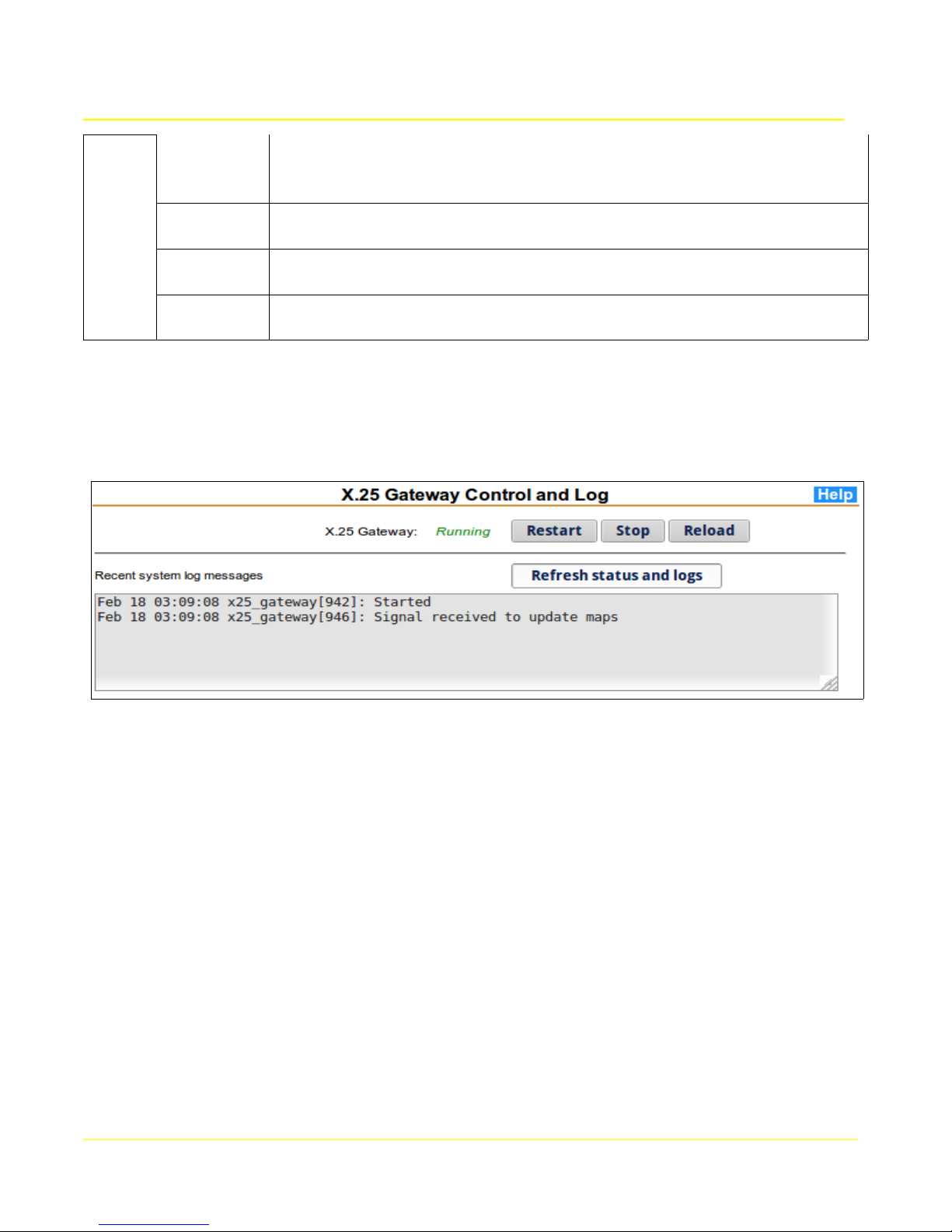
Microtronix Access User Guide
State The current state of the gateway session towards the X.25 logical channel
Disconnected / Connecting / Listening / Reconnect / Waiting / Connected /
Flow Control
Interface The local interface being used for the connection to the remote X.25 Host.
X.25
Calling
address
Called
address
May be one of: WAN 0, WAN 1, or XOT
The X.121 address of the initiator of the X.25 connection.
The X.121 address of the X.25 destination.
8.4 Control and Log
This page provides status and control of X.25-TCP gateway application. System log messages
pertinent to this application will be displayed.
The current status of the application are indicated by a Running or Stopped indicator. Stopping or
restarting the application will disconnect any active sessions and the associated TCP and X.25
communication sockets will be closed. If the application is stopped, then a Start button will be
displayed to start it again. The system log scrolling region shows significant application events since the
box was started. If there are any unusual errors, they will be shown in the log.
72
Page 73

Microtronix Access User Guide
9 SIP/SMDI MWI Gateway
The MWI Gateway provides routing and translation of Message Waiting Indicator (MWI) notifications
from VoIP Unified Messaging Servers and legacy Voice Mail Systems to one or more legacy or VoIP
telephone switches/ PBXs.
The MWI Gateway receives MWI input from either:
● Legacy VMS via SMDI messages over serial interface or TCP/IP socket
● VoIP UMS/VMS via SIP Notify messages over TCP/IP or UDP/IP sockets
Routing of MWI messages to multiple switches may be accomplished with:
● Domain name in the SIP Notify request URI
● Telephone number in the SIP Notify request URI
● Telephone number in the SMDI OP or RMV messages
MWI output (with message translation where necessary):
● SMDI via serial RS232 port directly to legacy PBX
● SMDI via TCP/IP to remote terminal server connected to serial port of legacy PBX
● SMDI via TCP/IP to PBX supporting SMDI over TCP
● Sip Notify (message-summary) via UDP/IP to VoIP PBX
9.1 SMDI to SIP Translation
When there is only single VoIP switch/PBX destination configured, routing is unnecessary and the MWI Gateway
acts as a simple SMDI to SIP translator.
73
Page 74

Microtronix Access User Guide
9.2 SIP to SMDI Translation
When there is only single legacy switch/PBX destination configured, routing is unnecessary and the MWI
Gateway acts as a simple SIP to SMDI translator.
9.3 MWI Routing
When there are multiple destination switches as in the diagram above, an optional telephone number database
may be used for routing MWI messages. The database is self-learning and may be populated from a comma
separated values (CSV) text file containing telephone number and matching switch interface number. A database
manger application allows adding, deleting, and reassigning phone numbers manually.
74
Page 75

Microtronix Access User Guide
9.4 Configuration
Configuration is accomplished by selecting the configuration forms from the main menu:
The MWI Gateway section provides links to the configuration and status pages for SMDI and SIP
interfaces.
The Terminal Server section provides links to the configuration and status pages for any local serial
interface that may be used. Refer to the Terminal Server configuration section for details.
9.4.1 UMS SIP Interface
The VoIP UMS or VMS connects to the MWI Gateway over an IP network as shown in the diagram
below. The UMS is configured with the IP address of the MWI Gateway and delivers unsolicited SIP
Notify messages over either TCP or UDP sessions. More than one UMS may connect to the MWI
Gateway.
The MWI Gateway needs to be configured to accept the incoming connections from the UMS and
extract the domain name and telephone number from one of the fields of the SIP Notify message.
75
Page 76
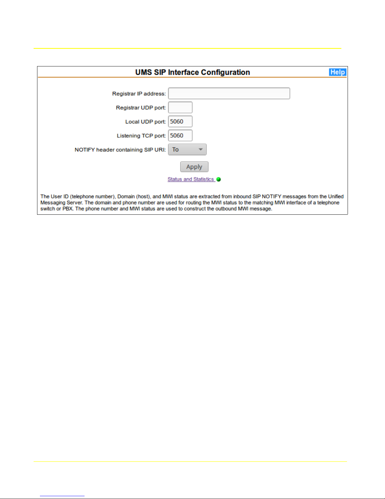
Microtronix Access User Guide
From main menu MWI Gateway section, select UMS SIP Interface to display the configuration form.
If the MWI Gateway needs to register itself, enter the Registar IP address and Registrar UDP port.
To accept incoming SIP Notify messages:
1) Specify the TCP and/or UDP port number to which the UMS interface will connect. The normal
default is port number 5060.
2) Select the SIP NOTIFY header field containing the SIP-URI that will be used for extracting userid
(telephone number) and domain name for routing the MWI message to a matching switch.
Click Apply to commit the settings and restart the application.
For additional information, click the Help button on the page.
The Status and Statistics link displays the current running status of the application with a red or green
indicator. Clicking the link will display the application status and message statistics.
76
Page 77

Microtronix Access User Guide
9.4.2 VMS SMDI Interface
The VMS connects to the MWI Gateway via an SMDI link which may be one of the following as
depicted in the diagram below:
If connecting directly using a serial port, the SMDI interface connects to the built-in TCP Terminal
Server at the local IP address, 127.0.0.1. If connecting remotely via TCP/IP, the IP address of the remote terminal server or of the VMS itself will be used for initiating the connection. Leave the IP address blank if accepting a connection from any source.
From the main menu MWI Gateway section, select VMS SMDI Interface to display the configuration
form.
77
Page 78

Microtronix Access User Guide
To configure a VMS SMDI interface:
1) Select SMDI protocol. To disable the interface, set protocol to Disabled.
2) If initiating a connection towards the VMS, specify the IP address and TCP port number of the
remote or local terminal server that corresponds to the serial link of the VMS. If accepting
connections from any source, leave the IP field blank to listen for a connection. Selecting TCP
port 0 also disables this interface.
3) Click the Apply button to commit changes made.
The Status and Statistics field is a link that displays the current running status of the corresponding
application with a red or green indicator. Clicking the link will display the application status and SMDI
message statistics.
For additional configuration information, click on the Help button.
78
Page 79

Microtronix Access User Guide
9.4.3 Switch Interfaces Configuration
Incoming MWI messages from UMS and/or VMS systems may be converted to legacy SMDI or NEC
MCI, or to VoIP SIP. The MWI messages can be directed to a single switch or PBX, or routed to
multiple switches and PBX's via DN (Directory Number) using a self-learning DN database.
Configuration of up to 10 destination switches is accomplished by selecting a protocol, and configuring
the IP address and TCP port number of the internal Terminal Server, external terminal server, external
SMDI Translator, or PBX.
From the main menu MWI Gateway section, select Switch Interfaces to display the configuration form,
and table of switch interfaces.
79
Page 80

Microtronix Access User Guide
To configure switch interfaces, repeat the following steps for each interface:
1) Below the form, a table labeled Switch/PBX Interfaces is displayed. This table lists the switch
Interfaces with their current configuration and status.
2) To edit or enable a Switch Interface setting, select the corresponding radio button on the right
side of the interface table. The current values will populate the fields in the form above. The
interface unit number will display in the Interface Number box.
3) Domain: field - specify the domain name that will be used to match the domain field of the SIPURI field of incoming SIP Notify messages. Messages matching this will be delivered to this
switch. If the name is entered as “default”, then messages that have no other match will be
delivered to this switch. If left blank, then only telephone number lookup will apply for this
switch.
4) Select the switch's protocol in the Protocol drop-down list.
5) Enter the IP Address and TCP Port Number of the Switch or the terminal server that
corresponds to the serial link connected to the Switch. To initiate a connection, specify the
external IP address. To accept a connection, set the IP to 0.0.0.0. The built-in terminal server
can be specified by using the local loopback IP address (127.0.0.1). The TCP port specified will
be 400x, where x is equal to the SMDI-Switch Interface number (ie. Device Port 0 = 4000).
6) For SMDI, specify the SMDI keepalive interval, which is the time it takes in seconds between
receiving a response to a heartbeat message and when the next heartbeat message will be
sent.
7) Click the Apply button to commit changes made.
For additional configuration information, click on the Help button.
The Interface number field in the Switch Interfaces table is a link that displays the current running
status of the corresponding application with a red or green indicator. Clicking the link will display the
application status and message statistics.
When multiple switches are to be configured, start with the switch with the most telephone numbers,
followed by switches with decreasing numbers. This increases the likelihood of an early match when
the MWI router application is learning a new number. Assign an interface number for each stating with
0.
If destination switches are addressed by the UMS by a unique domain name, enter it in the Domain
field. Lookup by telephone number in the database will not be necessary unless there are exceptions.
The following sections illustrate the possible connection types to the switches or PBX's.
80
Page 81
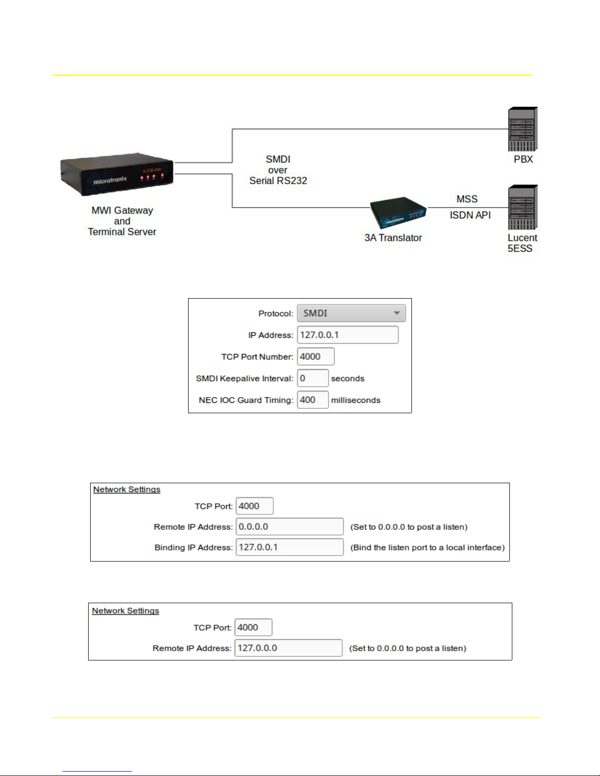
Microtronix Access User Guide
9.4.3.1 Serial Via Internal Terminal Server
Select an interface number by clicking it's Select to edit button to display it's configuration in the form.
Select the protocol SMDI or NEC MCI to match the switch interface.
To initiate a connection to the internal Terminal Server's serial interface, choose the local IP address
(127.0.0.1) and port number associated with the Terminal Server serial interface connected to the
switch. The Terminal Server Remote IP address should be set to 0.0.0.0 to listen.
To accept a connection from the terminal server, set the IP Address to 0.0.0.0. The Terminal Server
Remote IP address should be set to 127.0.0.0 to initiate the connection.
Click the Apply button.
81
Page 82

Microtronix Access User Guide
Click on the Serial-TCP link in the Terminal Server menu section to configure the local serial interface
connected to the switch.
Select the local interface connected to the switch and configure the Serial Settings to match the
attached switch interface. Configure a TCP port to match, and set Remote IP address to 0.0.0.0 to
listen for the local connection or 127.0.0.1 to initiate a local connection. Configure the Serial Settings to
match the attached switch interface.
82
Page 83
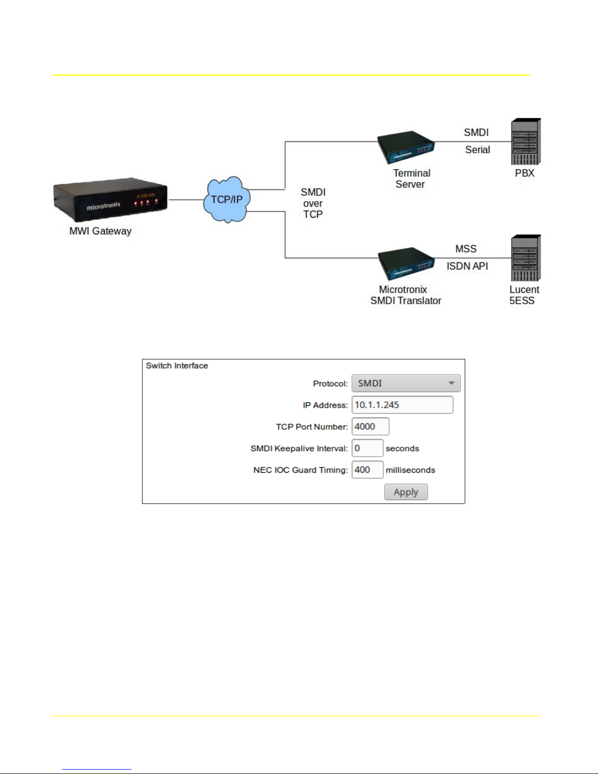
Microtronix Access User Guide
9.4.3.2 Serial Via External Terminal Server or Translator
Select an interface number by clicking it's Select to edit button to display it's configuration in the form.
Select the protocol SMDI or NEC MCI to match the switch interface.
To initiate a connection to the external terminal server's serial interface, configure it's IP address and
port number associated with it's serial interface connected to the switch. The remote terminal server
should be set to listen.
To accept a connection from the remote terminal server, set the IP Address to 0.0.0.0. The terminal
server Remote should be set to the IP address of the MWI Gateway to initiate the connection.
Click the Apply button.
83
Page 84

Microtronix Access User Guide
9.4.3.3 TCP/IP Direct to PBX
Select an interface number by clicking it's Select to edit button to display it's configuration in the form.
Choose Protocol SMDI if the PBX supports SMDI over TCP, and set the PBX's IP address and TCP port
number if the PBX is accepting connections. Set IP address to 0.0.0.0 to accept a connection.
Choose Protocol SIP if the PBX supports it, and set the PBX's IP address and TCP port number if the
PBX is accepting connections.
84
Page 85

Microtronix Access User Guide
9.5 MWI Test
9.5.1 Overview
The MWI Gateway can generate MWI messages internally by using the MWI Test page . Choose
the main menu option to display the test page.
The test page has 3 input fields for selecting a telephone number, on/off indicator, and message
format; and a Test button to initiate the test.
9.5.2 Telephone number (DN)
Enter the telephone number of the telephone that should receive an MWI message. The maximum
number of digits is 14. A single digit can be sent as a “keep-alive” signal that should invoke a negative response.
9.5.3 Message Waiting Indication
Choose ON or OFF depending on the desired affect on the telephone. Sending one then the other in
successive tests should cause a toggle of the specific indicator on the telephone. This could be a
stutter tone, lamp, or a test message depending on the type of phone and switch/PBX to which the
phone is attached.
9.5.4 Message format
Choose SIP Notify or SMDI as the source generator for the message.
If SIP Notify is chosen, a SIP Notify “messge-summary” is sent via the Listening TCP port of the
UMS SIP Interface. The port number shoul be non-zero. The SIP interface will forward the message to the MWI Gateway for delivery to it's routed destination switch/PBX.
If SMDI is chosen, an SMDI message is send via the listening TCP Port Number of the VMS Inter-
face. The VMS interface must not be in use by another source, and must be configured for listening
on a non-zero TCP Port Number, IP Address blank or set to 0.0.0.0, and Protocol set to SMDI.
9.5.5 Test Button
Click on the Test button to generate and send the MWI mesage to the selected input interface, and
observe the target telephone. Messages will be displayed in a new window to reflect the progress.
85
Page 86

Microtronix Access User Guide
9.6 Telephone Number Database
9.6.1 Overview
If MWI routing to multiple switch destinations is done by telephone number, the USB flash drive will
contain a telephone number SQL database. The database is initially empty unless pre-populated by
arrangement with Microtronix. A telephone number record has 3 fields:
1) Telephone number (up to 14 digits)
2) Switch interface number (matching switch or PBX)
3) Last received message waiting indication (ON / OFF)
The MWI Gateway will use the telephone number extracted from incoming SIP Notify or SMDI MWI
messages to route it to a matching switch by looking it up in the database.
9.6.2 Learning Telephone Numbers
If the telephone number does not yet exist in the database, a learning process begins. A record is
added and the telephone number assigned to the first available switch interface (lowest interface
number). The MWI value is also saved in case the switch rejects the phone number. The MWI message is sent to the switch, and if it is rejected, the phone number and MWI are used to send a message to the next available switch. The phone number is reassigned to the new switch. This process
is repeated until a switch has accepted the number, or all have rejected it. If all switches reject the
phone number, it will be asssigned to switch interface number 99, and a log event generated.
If the telephone number extracted already exists (has been accepted) in the database, an received
MWI message is forwarded to the assigned interfacebut if that switch subsequently rejects the telephone number, the telephone number is re-assigned to the next highest switch interface number and
the learning process resumes.
If a telphone number becomes assigned to switch interface 99, the Database Manager web page
can be used to manually reassign or delete it.
9.6.3 Database Manager
The Database Manager web page can be used to:
● find a telephone number switch interface assignment
● find a range of telephone number switch interface assignments
● find the numbers assigned to a switch interface
● reassign the switch interface for a phone number
● delete a phone number record
● add a new phone number record
86
Page 87

Microtronix Access User Guide
9.7 SMDI Messaging Examples
1) SIP Notify message-summary received from the UMS contains the following fields:
● SIP-URI: sip:551234567@domain1
● message content: Messages-waiting: yes
If enabled, the telephone number 55512134567 is looked up in the database for the destination switch
interface. If not in the database, the switch interfaces are scanned for a domain name match to
”domain1” starting at the lowest configured switch interface.
When a switch interface is determined and it is SMDI, the telephone number is used to construct the
SMDI MWI message to be sent to the matching switch.
OP:MWI 5551234567!<ctrl-D>
2) SIP Notify message summary received from the UMS contains the following fields:
● SIP-URI: sip:551234567@domain1
● message content: Messages-waiting: no
An SMDI MWI message will be sent to the matching switch.
RMV:MWI 5551234567!<ctrl-D>
3) If a transmitted SMDI MWI message contains a telephone number not assigned to the destination
switch, it will respond with an SMDI invalid message.
MWI5551234567 INV<cr><lf><ctrl-Y>
This will cause the MWI Gateway to remove the current SMDI interface assignment in the database
and re-assign to the next available switch interface number. It will transmit an MWI message to the
next switch (could be SIP Notify or SMDI).
9.8 Standards
● SMDI: Simplified Message Desk Interface (Bellcore TR-NWT-000283)
● RFC 3261: Session Initiation Protocol (SIP)
● RFC 3265: Session Initiation Protocol - Specific Event Notification: (EXT. of 3261)
● RFC 3842: A Message Summary and MWI Event Package for SIP
● RFC 3966: The tel: URI for telephone numbers
● ITU-T E.123 Notation for national and international telephone numbers
87
Page 88

Microtronix Access User Guide
10 Statistics & Logs
This section provides access to statistics and logs. Click on each item in this section of the main menu
to display the statistic and log pages.
10.1 Interface Statistics
The statistics page provides statistical information on all the active network interfaces. The statistics
are accumulated until the next system restart or power up.
The 2 tables show the Receive and Transmit statistics for all network interfaces (IP and HDLC).
88
Page 89

The following tables provide the meaning of each field.
Receive Statistics
Parameter Description
Interface The active network interface:
eth0 – Ethernet
lo – loopback interface (127.*.*.*)
hdlc0 – WAN 0
hdlc1 – WAN 1
Bytes The number of bytes received by the interface
Packets The number of packets received by the interface
Errs The total number of receive errors detected, including CRC errors
Drop The number of dropped packets on the network interface
Fifo The number of FIFO buffer errors
Frame The number of packet framing errors
Compressed The number of packets compressed packets received
Multicast The number of multicast packets received
Microtronix Access User Guide
Transmit Statistics
Parameter Description
Interface The active network interface
Bytes The number of bytes transmitted by the interface
Packets The number of packets transmitted by the interface
Errs The number of transmit errors detected
Drop The number of packets dropped
Fifo The number of FIFO buffer errors
Colls The number of collisions
Carrier The number of carrier losses detected
Compressed The number of compressed packets transmitted
89
Page 90

Microtronix Access User Guide
10.2 System Logs
This page provides an interface for viewing kernel ring buffer and system log.
10.2.1 Log View Parameters
Log file: The file to view. To view or refresh the display of a log file, select the desired file from
the list provided and click the “View / Refresh” button.
Lines from the end: To restrict the output to a certain number of lines, enter the desired
number of lines and click “View / Refresh”. If other filters are also in effect or there fewer lines
available than entered, then the total number of displayed lines may be less.
Date: To restrict the log output to a specific month, day, hour or minute, select the desired value
and click “View / Refresh”. If the button labeled “Today” is clicked, then the month and day
selections will be changed to the values for that day. To clear a date filter, select the first option
in the list, which will consist of a string with a dash on each end. To clear all date selections,
click the button labeled “Clear”.
Freeform text: To restrict output to lines containing a specific string, enter a string in this field.
Some basic regular expressions are supported.
90
Page 91

Microtronix Access User Guide
11 Cables and Connectors
11.1 NETWORK - 10/100 Ethernet Interface
The 10/100 Base-T Ethernet port provides a standard twisted pair interface on an RJ45 socket.
Pin # Function
1 Transmit +
2 Transmit 3 Receive +
4 n/c
5 n/c
6 Receive 7 n/c
8 n/c
11.1.1 Ethernet Cables
A standard RJ45 Ethernet patch cable (straight-through) may be used to connect to a hub/switch, or
direct connection to a PC for initial configuration.
Ethernet cable part numbers
811-W6002-06 RJ45 Ethernet straight through patch cable (blue), 6 ft
91
Page 92
Microtronix Access User Guide
11.2 WAN Interface – Synchronous Operation
The WAN interface provides a choice of RS232 (V.24), RS530, RS530A, RS449, X.21, or V.35 signals
in a DB25F connector with standard RS530 DCE pin configuration.
When configured for synchronous or X.25 operation, the interface name is hdlc0 (WAN port 0), and
hdlc1 (WAN port 1) on the Access 4000 model.
In RS530, RS449, and X.21 modes, all signals are balanced and have 2 pins per function (A/B). In
RS232, only single ended signals are used with a common ground (SG), and the B pins are not used.
In V.35 mode, control signals are unbalanced, and data/clock signals are balanced. All balanced
signals (A and B) require twisted pair wires in the cable. Unbalanced signals (A only) do not.
The following table shows the RS530 pin configuration of the WAN port.
Pin # Direction Signal Name
1
2
3
4
5
6
7
8
9
10
11
12
13
14
15
16
17
18
19
20
21
22
23
24
25
--- FG
input TxD A
output RxD A
input RTS A
output CTS A
output DSR A
--- SG
output DCD A
i/o RxC B
output DCD B
input (E)TxC B
output TxC B
output CTS B
input TxD B
output TxC A
output RxD B
i/o RxC A
input RTS B
input DTR A
output DSR B
input DTR B
input (E)TxC A
Note: Receive clock (RxC A/B) on pins 17/9 is bi-directional and depends on the clock configuration of
the port. Transmit clock (TxC A/B) is either output on pins 15/12 or input on pins 24/11 depending on
the clock configuration. Refer to the following sections for appropriate cabling for each clock
configuration.
92
Page 93

Microtronix Access User Guide
11.2.1 Connecting to a DTE Device
The primary WAN port is configured as a DCE, so can normally connect to a DTE device using a
straight through cable. The port is configured to provide DCE clock. The transmit clock (pins 15/12)
and the receive clock (pins 17/9) are sourced from a single baud rate generator, so the attached device
may use either signal as a single source for both receive and transmit clock.
If the port is configured to generate DCE clocks internally (Clock source = Internal), then a baud rate
is chosen and the internal baud rate generator is used to source the RxC and TxC clock signals. Pins
24/11 are not used and may be omitted from the cable.
If the port is configured to receive the clock from the DTE (Clock source = DTE), then the received
ETxC signal (pin 24/11) is used to generate the output DCE clock signals RxC and TxC.
Pin # Direction Signal Name
17 output RxC A
9 output RxC B
15 output TxC A
12 output TxC B
24 input ETxC A
11 input ETxC B
93
Page 94

Microtronix Access User Guide
11.2.1.1 Straight Through Cables
The following table shows the pin configurations and connector types for each interface type.
DB25M
RS530
DB25F
RS232
DB25F
V.35
M34F
X.21
DB15F
1 1 1 A 1 1
2 2 2 P 2 4
3 3 3 R 4 6
4 4 4 C 7
5 5 5 D 9
6 6 6 E 11
7 7 7 B 8 19,37
8 8 8 F 5 13
9 9 X 13 26
10 10 12 31
11 11 W 35
12 12 AA 23
13 13 27
14 14 S 9 22
15 15 15 Y 5
16 16 T 11 24
17 17 17 V 6 8
19 19 25
20 20 20 H 3 12
22 22 29
23 23 10 30
24 24 24 U 17
RS449
DB37F
Part Number Description
811-SC6MF DB25M-DB25F, RS232/V.24 straight through cable, 6 ft
W4025-RS530-DCE-n DB25M-DB25F, RS530 straight through cable, custom length
W4025-V35-DCE-001 DB25M-M34F, V.35 adapter cable, 1 ft
W4025-X21-DCE-001 DB25M-DB15F, X.21 adapter cable, 1 ft
W4025-RS449-DCE-001 DB25M-DB37F, RS449/V.36 adapter cable, 1 ft
Other lengths are available by special order.
94
Page 95

Microtronix Access User Guide
11.2.2 Connecting to a DCE Device
Because the port is configured as a DCE, a crossover or tail circuit cable must be used to connect to
another DCE device (for example, a modem), so that the WAN port emulates a DTE.
11.2.2.1 Crossover Cables
The port is configured (Clock source = External) to receive the clock signals from the DCE. The
receive clock is on pins 17/9, and transmit clock is on pins 24/11 (not the usual 15/12).
Pin # Direction Signal Name
17 input RxC A
9 input RxC B
24 input TxC A
11 input TxC B
Note: If the DCE uses the same source for generating the clock for both receive and transmit, then the
port can be configured for a single clock (Clock source = RxFromTx) on pins 17/9 and pins 24/11 may
be omitted.
The following table shows the pin configurations and connector types for each supported interface type.
The first column, DB25M, is the end of the cable that connects to the WAN port.
DB25M
1 1 1 A 1 1
2 3 3 R 4 6
3 2 2 P 2 4
4 5 5 D 9
5 4 4 C 7
6,8 20 20 H 3 12
7 7 7 B 8 19,37
9 12 AA 13 23
11 9 X 26
13 19 25
14 16 T 11 24
16 14 S 9 22
17 15 15 Y 6 5
19 13 27
20 6,8 6,8 E,F 5 11,13
22,10 23 10 30
23 22,10 12 29,31
24 17 17 V 8
RS530
DB25M
RS232
DB25M
V.35
M/34M
X.21
DB15M
RS449
DB37M
95
Page 96

Microtronix Access User Guide
Part Number Description
W4025-RS530-DTE-001 DB25M-DB25M, RS530 crossover cable, 1 ft
W4025-V24-DTE-001 DB25M-DB25M, RS232/V.24 crossover cable, 1 ft
W4025-V35-DTE-001 DB25M-M34M, V.35 crossover adapter cable, 1 ft
W4025-X21-DTE-001 DB25M-DB15M, X.21 crossover adapter cable, 1 ft
W4025-RS449-DTE-001 DB25M-DB37M, RS449/V.36 crossover adapter cable, 1 ft
Other lengths are available by special order.
96
Page 97

Microtronix Access User Guide
11.2.2.2 Tail Circuit Cables
If the port is configured to connect to another DCE using a tail circuit cable (Clock source =
TxFromRx), then a baud rate is chosen and the internal baud rate generator is used to source the
output RxC clock. Receive and transmit data use the ETxC (pin 24/11) to derive clocking.
Pin # Direction Signal Name
17 output RxC A
9 output RxC B
24 input TxC A
11 input TxC B
The following table shows the pin configurations and connector types for each supported interface type.
DB25M
1 1 1 A 1
2 3 3 R 6
3 2 2 P 4
4 8 8 F 13
6 20 20 H 12
7 7 7 B 19, 37
8 4 4 C 7
9 11 W 35
10 19 25
11 9 X 26
14 16 T 24
16 14 S 22
17 24 24 U 17
19 10 31
20 6 6 E 11
22 23 30
23 22 29
24 17 17 V 8
RS530
DB25M
RS232
DB25M
V.35
M/34M
RS449
DB37M
11.2.3 Split clock configuration
When the primary WAN port is configured for split clock (Clock source = TxInt), the clock pins are
configured as shown in the table below. The receive clock (pin 17/9) is generated internally, and the
transmit clock is derived from the external source on pin 24/11. Pins 15/12 are not used and should be
left disconnected. Since this is a custom configuration, the cable may be either straight through or
crossover, depending on the application.
97
Page 98

Microtronix Access User Guide
Pin # Direction Signal Name
17 output RxC A
9 output RxC B
24 input TxC A
11 input TxC B
98
Page 99
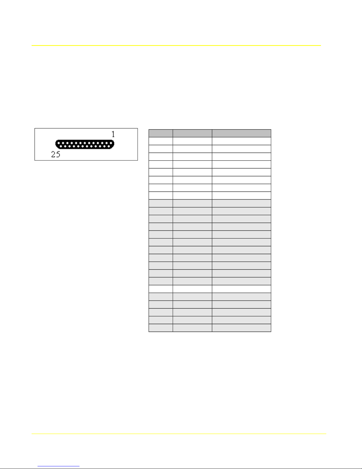
Microtronix Access User Guide
11.3 WAN Interface – Asynchronous / Serial Operation
The WAN interface provides RS232 (V.24) in a DB25F connector with standard DCE pin configuration.
When configured for asynchronous / serial operation, the interface names are WAN 0 hdlc0), and WAN
1 (hdlc1) on the Access 4000 model.
The following table shows the RS232 pin configuration of the WAN interface when configured for
asynchronous operation.
Pin # Direction Signal Name
1
2
3
4
5
6
7
8
9
10
11
12
13
14
15
16
17
18
19
20
21
22
23
24
25
--- FG
input TxD
output RxD
input RTS
output CTS
output DSR
--- SG
output DCD
input DTR
11.3.1 Connecting to a DTE Device
The WAN interface is configured as a DCE, so can normally connect to a DTE device using standard
straight through or 9 pin adapter cables.
11.3.1.1 Straight Through Cables
The table shows the pin configurations and connector types of the cables. The first column, DB25M, is
the end of the cable that connects to the WAN interface. The other columns depict the connector and
pin configuration of the other end of the cables connecting to DTE device.
99
Page 100

Microtronix Access User Guide
DB25M DB25F DB25M DB9F
1 1 1 2 2 2 3
3 3 3 2
4 4 4 7
5 5 5 8
6 6 6 6
7 7 7 5
8 8 8 1
20 20 20 4
The following cables are used to connect to DTE devices. Usually a DTE device has a male connector,
but some have a female connector requiring a straight through gender changer. Connecting to a DB9M
PC COM port requires a 9-pin adapter.
Part Number Description
811-SC6MF DB25M-DB25F, RS232 straight through cable
811-SC6MM DB25M-DB25M, RS232 straight through gender changer
[284-MC1MF DB25M-DB9F, RS232 adapter cable
11.3.2 Connecting to a DCE Device
Because the WAN interface is configured as a DCE, a standard null modem (crossover) cable must be
used to connect to another DCE device (for example, a modem), so that the WAN emulates a DTE.
11.3.2.1 Null Modem Cables
The table shows the pin configuration and connectors. The cable is symmetrical, so it doesn't matter
which end connects to the WAN interface.
DB25M DB25M
1 1
2 3
3 2
4 5
5 4
6 [+8] 20
7 7
20 6 [+8]
Note that pins 6 and 8 (DSR and CD) may be wired together at each end. Alternatively, either 6 or 8
may be used for cross-connecting to pin 20 (DTR) at the other end.
100
 Loading...