

MICROTRONIX Access 1000, Access 4000, Access 4002-S04, Access 4002-N04, Access 1000-N04 Quick Start Manual
...Page 1
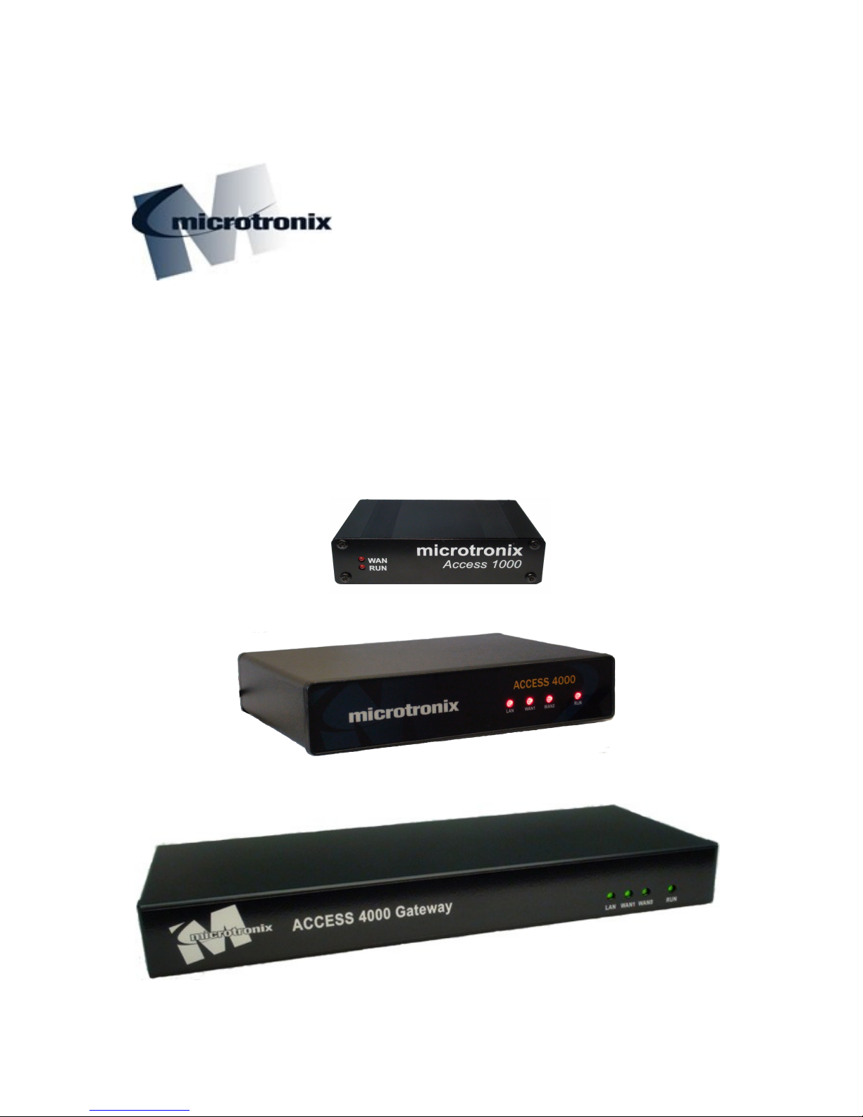
Microtronix
Access 1000 & 4000
X.25 – TCP/IP Gateway
Quick Start Guide 0.10.4
Page 2

Microtronix Access X.25–TCP/IP Gateway
Table of Contents
1 Overview............................................................................................................................................. 4
1.1 Access X.25-TCP/IP Gateway models.......................................................................................... 4
1.2 WAN interface............................................................................................................................... 5
1.3 Console interface.......................................................................................................................... 5
1.4 Network (Ethernet) interface......................................................................................................... 5
1.5 USB interface................................................................................................................................ 5
2 Package Check List............................................................................................................................ 6
3 Quick Start Guide............................................................................................................................... 7
3.1 Installation..................................................................................................................................... 7
3.2 Ethernet / IP Port........................................................................................................................... 7
3.2.1 Web Interface (htttp / https)...................................................................................................................7
3.2.2 Terminal Interface (telnet / ssh).............................................................................................................7
3.3 Console Port (Optional)................................................................................................................. 7
3.3.1 U-Boot Command Access.....................................................................................................................7
3.3.2 Setting Default IP Parameters................................................................................................................7
3.3.3 Emergency IP Address Recovery..........................................................................................................8
3.3.4 System Firmware Updates.....................................................................................................................8
3.4 Configuration Web Interface.......................................................................................................... 9
3.5 IP Network Configuration............................................................................................................ 10
3.5.1 Verifying IP Network..........................................................................................................................11
3.5.2 Monitoring IP Network........................................................................................................................11
3.6 X.25 Configuration......................................................................................................................12
3.6.1 Layer 1 – Physical...............................................................................................................................12
3.6.2 Layer 2 – Data Link.............................................................................................................................13
3.6.3 Layer 3 – Packet..................................................................................................................................14
3.7 Verifying X.25 Interface............................................................................................................... 15
3.7.1 X.25 Status..........................................................................................................................................15
3.7.2 LAPB Status........................................................................................................................................15
3.7.3 HDLC Interface Status.........................................................................................................................15
3.7.4 Interface Statistics................................................................................................................................16
3.7.5 X.25 Monitor.......................................................................................................................................16
3.7.6 X.25 Logical Channel Status...............................................................................................................17
3.8 X.25 to TCP Routing Configuration............................................................................................. 18
3.8.1 Identify inbound X.25 connection.......................................................................................................18
3.8.2 Generate outbound TCP/IP connection................................................................................................18
3.8.3 Specify Conversion or Encapsulation Method.....................................................................................19
3.9 TCP to X.25 Routing Configuration............................................................................................. 20
3.9.1 Identify inbound TCP/IP connection...................................................................................................20
3.9.2 Specify Conversion or Encapsulation Method.....................................................................................20
3.9.3 Generate outbound X.25 connection....................................................................................................21
3.10 Verify X.25 Gateway Status.......................................................................................................22
3.10.1 Connection Status..............................................................................................................................22
3.10.2 Control & Log...................................................................................................................................22
3.11 Synchronous Server Configuration............................................................................................ 23
www.microtronix.com 2
Page 3

Microtronix Access X.25–TCP/IP Gateway
3.11.1 Device Settings..................................................................................................................................23
3.11.2 Network Settings...............................................................................................................................23
3.11.3 Update and Start the Server...............................................................................................................24
3.11.4 Verify Sync Server Connection.........................................................................................................24
3.12 Terminal Server Configuration................................................................................................... 25
3.12.1 Serial Settings....................................................................................................................................25
3.12.2 Conversion Settings...........................................................................................................................26
3.12.3 Network Settings...............................................................................................................................26
3.12.4 Update and Start the Server...............................................................................................................26
3.12.5 Verify Terminal Server Connection...................................................................................................27
4 Cables................................................................................................................................................ 28
4.1 WAN Cables................................................................................................................................ 28
4.1.1 Connecting to a DCE device................................................................................................................28
4.1.2 Connecting to a DTE device................................................................................................................28
4.2 Serial and Console Cables.......................................................................................................... 29
4.2.1 Connecting to a DCE device................................................................................................................29
4.2.2 Connecting to a DTE device................................................................................................................29
5 Encapsulation Message Formats.................................................................................................... 30
5.1 MBIT (2-byte count field)............................................................................................................. 30
5.2 RFC1006 (ISO TP)...................................................................................................................... 30
5.3 Q-MBIT (extended RFC1006)..................................................................................................... 30
5.4 XOT (RFC 1613 – X.25 Over TCP)............................................................................................. 30
5.5 OFTP (RFC 5024)....................................................................................................................... 30
5.6 RBP (Cisco Record Boundary Preservation)............................................................................... 30
5.7 QRBP.......................................................................................................................................... 31
5.8 AEPN.......................................................................................................................................... 31
6 Contact Microtronix.......................................................................................................................... 32
www.microtronix.com 3
Page 4
Microtronix Access X.25–TCP/IP Gateway
1 Overview
The Microtronix Access X.25–TCP/IP Gateway provides conversion between X.25 and TCP/IP
devices, or X.25 encapsulation over TCP (XOT). In addition, raw synchronous and serial terminal
servers may be configured.
A web interface allows for configuration and monitoring from any Internet browser, and telnet/SSH
servers allow for connecting to the command line interface for additional management.
1.1 Access X.25-TCP/IP Gateway models
The following table shows the available interfaces and connector type of each Access Gateway model.
Model
1000-S04
1000-N04
4002-S04
4002-N04
4002-N04-RM
4002-N44-RM
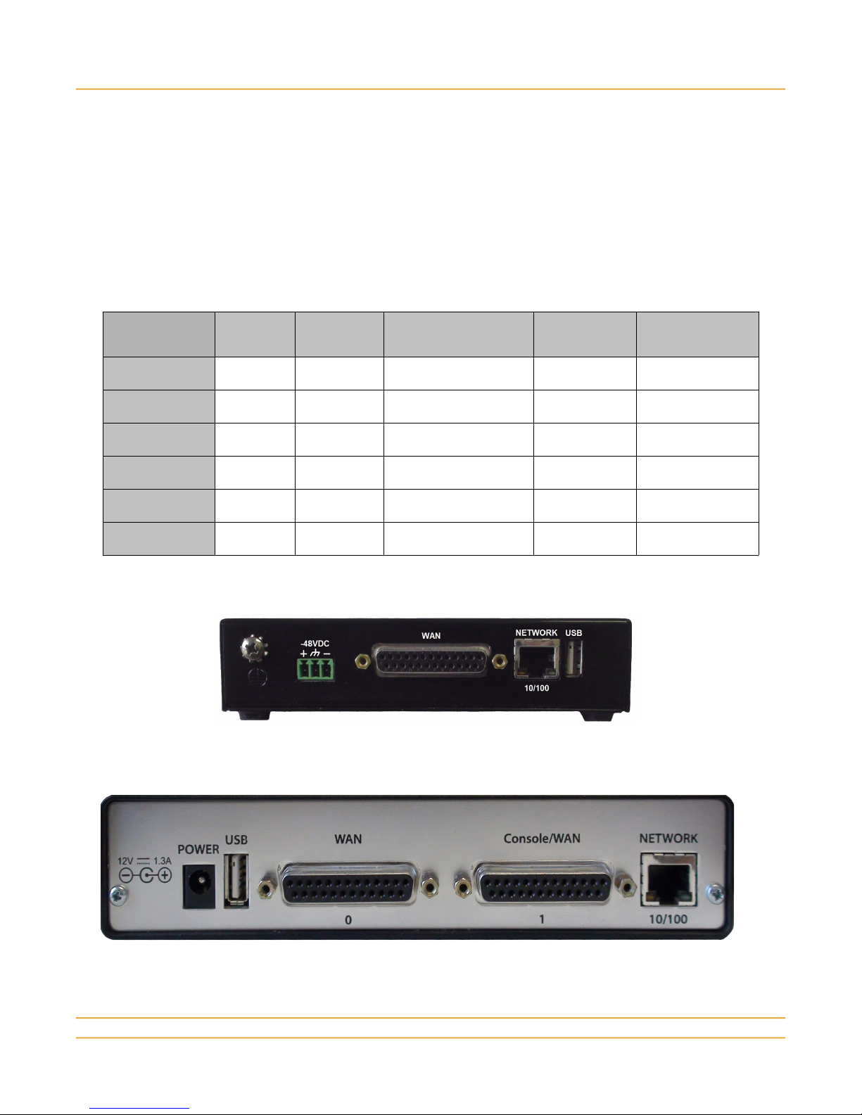
The following pictures of the rear plate of each model illustrate the interfaces and connectors.
RJ45
Ethernet
1 1 external 0
1 1 external 0
1 2 external or internal 0
1 2 external or internal 0
1 2 internal 0
1 2 (not available) 4
DB25F
WAN ports
USB host port
Interface
DB9M
Serial ports
Power
connector
AC adapter
-48VDC
AC adapter
-48VDC
-48VDC
-48VDC
Model 1000-S04-U Model 4002-S04
Model 1000-S04-U Model 4002-S04
www.microtronix.com 4
Model 1000
Model 4002-S04
Page 5

Microtronix Access X.25–TCP/IP Gateway
Model 4002-N44-RM
The model name and serial number are printed on the label located on the bottom of the unit.
The following sections describe the each attributes and function of each interface type.
1.2 WAN interface
WAN ports support RS232/V.24 with speeds up to 128 Kbps, and V.35, X.21, RS530, RS449/V.36
interface types with speeds up to 10 Mbps, in a standard DB25F DCE connector. The ports may be
used for:
● X.25
● Synchronous Server
● Serial Terminal Server
The 1000 models have one WAN interface that doubles as the boot console, and the 4002 models have
two WAN interfaces with one that doubles as the Console port. See the notes under Console interface
below.
1.3 Console interface
The Console/WAN port may be used for:
● X.25
● Synchronous Server
● Serial Terminal Server
● System console port for configuration and monitoring
In addition, the Console/WAN port serves as the console for the boot program and operates in RS232
asynchronous mode during boot up. The boot command line interface may be invoked for system
management and emergency IP address recovery by entering a password during a 10 second interval
after power up.
1.4 Network (Ethernet) interface
The RJ45 NETWORK interface is 10/100 Ethernet with full auto-detection, supporting a rich set of
standard IP protocols.
1.5 USB interface
The USB 1.1 type A host port supports additional serial interface or storage devices:
● USB serial adapters (FTDI chipset only) for up to 8 additional Terminal Server interfaces
www.microtronix.com 5
Page 6

Microtronix Access X.25–TCP/IP Gateway
● USB flash drive for storing and moving files
The 4002-S04 and 4002-N04-RM models may be specially ordered with an internally mounted USB
flash drive with no external USB connector.
The 4002-N44-RM models have an internally mounted USB 4-port serial expansion card.
2 Package Check List
Check that the Access model received matches the order by comparing to the model number printed on
the label on the bottom of the unit.
Check that the package shipped contains the following items.
● Access Gateway unit as above
● Rack mount brackets (model 4002-Nxx-RM only)
● AC adapter with AC power cord or - 48VDC power cord
● DB9F-DB25M Console Cable
● RJ45 Ethernet patch cable (blue)
● RJ45 Ethernet crossover cable (red)
● DB25MF straight through RS232 WAN cable
The following optional items are available through special order, and may be included:
● Additional WAN or serial cable(s) – refer to the Cables section for part numbers
● USB serial adapter unit: 1, 2, 4, or 8 ports
● USB flash drive
● AC adapter for -48VDC unit
● Rack mount shelf for 1 or 2 model 4002-S0x units
www.microtronix.com 6
Page 7

Microtronix Access X.25–TCP/IP Gateway
3 Quick Start Guide
Configuration of the Access Gateway will require a PC or laptop with standard Internet browser like
Internet Explorer or Mozilla Firefox. Optionally, a serial COM port (or USB serial adapter) on the PC
with a terminal emulator application may be used to connect to the Console port.
3.1 Installation
1) The Access Gateway may be placed on a shelf in a rack, or mounted using a rack mount kit.
2) Connect to the IP network through the RJ45 10/100 Network port. To connect directly to the PC,
use the Ethernet cross cable (red).
3) Optional: Connect the Console port to the PC using the Console Cable. Refer to the “Console
Port” section below for instructions.
4) Connect AC/DC power adapter and AC power cord (or attach the -48VDC power cord)
5) Wait 30 seconds for the boot process to complete. The RUN led will start to blink.
3.2 Ethernet / IP Port
The Ethernet port can be used for initial configuration. The default IP address of the Access Gateway is
10.1.1.240/24. To connect via IP, set the PC's IP address to 10.1.1.200, and subnet mask to
255.255.255.0 (10.1.1.0/24).
3.2.1 Web Interface (htttp / https)
The Access Gateway has a web-based server for configuring and monitoring. Use any Internet
browser to connect to the web interface. Login is required with username “admin”, and default
password “admin”.
3.2.2 Terminal Interface (telnet / ssh)
The Access Gateway will also accept Telnet or ssh client connections for advanced monitoring and
troubleshooting. The username is “root”, and the default password is “f0adA” (0=zero) for privileged
access, and “admin”, “admin” for non-privileged access.
3.3 Console Port (Optional)
The Console port offers system control access during the boot-up process. Boot messages will be
displayed if a PC COM port is connected using the Console Cable, and a terminal emulator like “putty”
or “HyperTerminal” is set for 9600-N-8-1.
3.3.1 U-Boot Command Access
After power up, there is a 10 second delay that allows U-Boot command access:
Autoboot in 10 seconds (Enter password to stop)...
if the password “foad” is typed while the message is displayed, the U-Boot prompt “A4K:>” will indicate
command readiness.
3.3.2 Setting Default IP Parameters
The default IP network parameters may be modified or added here as an alternative to the configuration
via the web interface. Enter the following commands to change the default IP address, netmask,
default gateway (if needed), and optionally a new system “hostname”
set ipaddr 10.1.1.240
set netmask 255.255.255.0
set gatewayip 10.1.1.1
www.microtronix.com 7
Page 8

Microtronix Access X.25–TCP/IP Gateway
set hostname MYNAME
save
boot
These defaults will remain in effect until again changed again in U-Boot, or explicitly changed via the
Ethernet configuration page in the web interface.
3.3.3 Emergency IP Address Recovery
The u-boot console may be used to recover a forgotten IP address. While in the U-Boot console, the
default IP address and other parameters may be displayed:
print ipaddr
print netmask
print gatewayip
If the default values are not in current effect, they may override the system-defined values temporarily
by setting new default values (if desired) and entering the U-Boot commands:
set runlevel 2
save
boot
When the system starts up, it will be using the default IP address information, and should be reachable
on that network. Browse into the web interface and access the Ethernet page to view the “forgotten”
values. Restart the system to get the U-Boot console, and reset run level:
set runlevel
save
boot
The system will restart with the system-defined values.
3.3.4 System Firmware Updates
The u-boot console may also be used in conjunction with Microtronix support for applying firmware
updates, and emergency IP address recovery.
To apply firmware updates:
1) Obtain the kernel image (uImage) and/or filesystem image (jffs2.img) files from Microtronix
2) Start a tftpd server on the PC or an available file server
3) Place the file(s) in the tftpd default directory on the PC or server
4) Enter the PC or server IP address (example 10.1.1.200) using the u-boot commands:
set serverip 10.1.1.200
save
5) Load the new kernel image:
run updatekernel
6) Load the new filesystem image:
run updatejffs2
7) Start the system by re-applying power or typing the “boot” command.
www.microtronix.com 8
Page 9
Microtronix Access X.25–TCP/IP Gateway
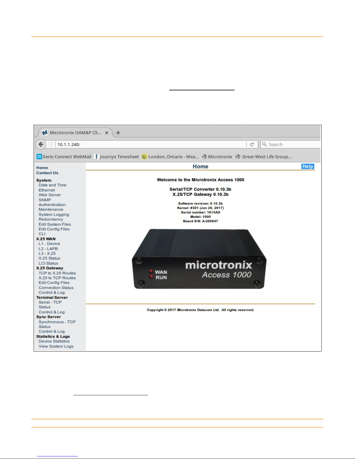
3.4 Configuration Web Interface
The default IP address of the Access Gateway is 10.1.1.240. The PC used to access the web interface
must be configured (temporarily) for an address in the same subnet, for example, 10.1.1.200. Connect
the PC to the same LAN, or temporarily use the red Ethernet crossover cable to connect directly to the
Access Gateway.
Open the web browser on the PC, and enter http://10.1.1.240 in the URL field. When
prompted by a popup window, login using default user name: admin, and password: admin.
The home page will be displayed with the main menu down the left hand side.
The Access Gateway can now be configured by selecting the main menu items. Each page
has a Help button in the upper right corner for viewing additional information specific to the
current page.
Note: If using Windows Internet Explorer, Compatibility View may need to be enabled. This can be
done by clicking on the “broken page” icon in the address field of the address bar, or by adding the IP
address using the Compatibility View Settings IE Tools menu.
www.microtronix.com 9
Page 10
Microtronix Access X.25–TCP/IP Gateway
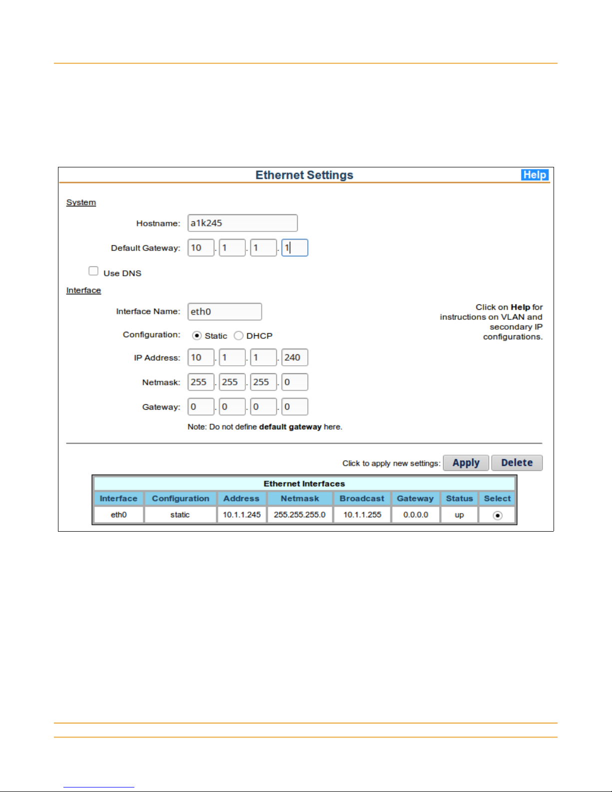
3.5 IP Network Configuration
To create or modify the IP network parameters different than the default values defined in U-Boot ,
obtain the new IP address, network mask, and default gateway values. Follow this procedure only if
you don't want the default values to be used in the running system.
From the main menu System section, select Ethernet to display the configuration form.
1) Modify the Hostname as desired.
2) Enter the new Default Gateway IP address, if needed.
3) Click on the Select button in the Ethernet Interfaces table corresponding to “eth0”.
4) Enter the new IP address and network mask.
5) Click the Apply button for the changes to be saved and to take affect.
Connect the Network port to the new network, if not already. Since the IP connection may be lost due
to the change, the new address may need to be entered in the browser. The Ethernet configuration
page displays the current status of the Ethernet interface.
For more information on additional network configuration, click the Help button on the page.
www.microtronix.com 10
Page 11

Microtronix Access X.25–TCP/IP Gateway
3.5.1 Verifying IP Network
Use ping from a PC or other station on the IP network to verify the Access Gateway is reachable.
Sometimes ARP cache tables are obsolete and need refreshing after an IP change.
The LAN led on the front panel will blink when there is activity on the Ethernet port.
If the PC used for configuration is still able to reach the Access Gateway, use telnet or ssh to connect to
the command line interface. Login using user name “root” and password “f0adA” (0=zero).
Enter the command “ifconfig eth0” to view the status and statistics of the Ethernet interface.
Use ping to test the connection to the default gateway or another station on the IP network. Enter the
command “ping a.b.c.d”, where a.b.c.d is the IP address in dotted notation.
To test the connectivity to a remote IP host that will be connecting to or receiving connections from the
Access Gateway, use ping to verify reachability.
3.5.2 Monitoring IP Network
Sometimes tracing the IP interface may be necessary to determine a problem. The standard tcpdump
utility is provided for this purpose. To run the tcpdump utility, make a telnet connection from a PC to
connect to the Access Gateway command line interface. Respond to the login request with the default
username “root” and password “f0adA” (0=zero). At the “#” prompt, enter the “tcpdump” command. It
can be entered with a number of command line options. Use the “-h” option to see a list of all available
options. The normal syntax is:
tcpdump -i INTERFACE -w OUTPUT_FILE EXPRESSION
where:
INTERFACE: primary “eth0”, loopback “lo”, secondary IP “eth0:1”, VLAN “eth0.1”
OUTPUT_FILE: File name must include one of the paths: “/tmp/” or “/mnt/usb1/”
EXPRESSION: any valid tcpdump expression like “tcp port 102” or “ip host 10.1.1.200”
To stop tcpdump, type control-C (Ctrl+C). The file can be FTP'd to the PC for display and analysis
using Wireshark (Ethereal).
For example, to monitor TCP port 102 on the Ethernet interface, and record the output into a file:
tcpdump -i eth0 -w /tmp/tcpdump.pcap tcp port 102
The loopback interface “lo” is used for internal connections (127.x.x.x):
tcpdump -i lo -w /mnt/usb1/tcpdump.pcap tcp port 1998
Care must be taken to NOT use an expression that would monitor the initiating telnet session.
For extended monitoring, the output file should be written to a USB-mounted flash drive (if the USB
port is not used for serial adapters) by using the path:
-w /mnt/usb1/tcpdump.pcap
To transfer a file to a PC, run FileZilla or WinSCP with the IP address of the Access. The local ftp, scp,
or sftp client commands can be used to push the file to the PC if it has the matching server.
www.microtronix.com 11
Page 12

Microtronix Access X.25–TCP/IP Gateway
3.6 X.25 Configuration
To configure a WAN port to match the attached X.25 equipment at all 3 layers of the X.25 protocol,
select each of the following items from the X.25 WAN main menu section:
3.6.1 Layer 1 – Physical
From the main menu X.25 WAN section, select L1-Device to display the form:
1) Select a device from the drop-down list (hdlc0 – WAN port 0 is the default).
2) Select the physical interface type to match the attached X.25 device.
3) For connection to a DTE device, select Internal Clock Source and an appropriate rate. For
connection to a DCE device or modem, select External (or rxfromtx) Clock Source.
4) Click the Status: Enable button
5) Click the Update button for the changes to be saved.
www.microtronix.com 12
Page 13

Microtronix Access X.25–TCP/IP Gateway
3.6.2 Layer 2 – Data Link
From the main menu X.25 WAN section, select L2–LAPB to display the form:
1) Select a device from the drop-down list (hdlc0 – WAN port 0 is the default).
2) For connection to a DTE device, select DCE; for connection to a DCE device, select DTE.
3) Configure the Window Size to match the attached device (usually 7).
4) Click the Update button for the changes to be saved.
www.microtronix.com 13
Page 14

Microtronix Access X.25–TCP/IP Gateway
3.6.3 Layer 3 – Packet
From the main menu X.25 WAN section, select L3–X.25 to display the form:
1) Select a device from the drop-down list (hdlc0 – WAN port 0 is the default).
2) For connection to a DTE device, select DCE; for connection to a DCE device, select DTE.
3) Configure the packet and window sizes to match the attached X.25 interface. A mis-match may
cause packet layer resets and data loss, or data stalls.
4) Configure SVC and PVC settings to match the attached X.25 interface. A mis-match may
cause unanswered call requests.
5) Click the Restart WAN Interface checkbox to cause all the changes to take affect.
6) Click the Update button for the changes to be saved and take affect.
Repeat these steps for each port to be configured for X.25.
For additional information, click the Help button on the page.
www.microtronix.com 14
Page 15

Microtronix Access X.25–TCP/IP Gateway
3.7 Verifying X.25 Interface
The WAN led on the front panel will illuminate when the X.25 link is established at all 3 layers of the
WAN port. To view detailed status of each layer of the X.25 interface, click X.25 Status in the main
menu X.25 WAN section.
Start at the top level (X.25) and work down to troubleshoot.
3.7.1 X.25 Status
Shows the current status of the packet layer. If in “r1:Ready” state, then all 3 layers are established. If
not, then:
● There is saved configuration that has not become effective with a restart. Restart the interface.
● There is a problem at the LAPB or HDLC levels.
● The attached device does not support X.25, or has become disabled.
3.7.2 LAPB Status
Shows the current status of the data link layer – should be in “Info Transfer” state. If not, then:
● There is a problem at the HDLC level.
● The emulation mode (DTE/DCE) is not set correctly. It must be opposite to the attached device.
3.7.3 HDLC Interface Status
Shows the current operational mode and status of the interface signals.
If the current mode does not match the configuration, then the port needs to be restarted.
If the asserted signals (DSR, CD, CTS) are OFF, then the port is disabled and needs to be configured
www.microtronix.com 15
Page 16

Microtronix Access X.25–TCP/IP Gateway
to have Status enabled, then restarted.
If the received DTR and RTS signals are off, then:
● The cable is not connected.
● The cable is the wrong DTE/DCE gender or wrong pin configuration for the interface.
● The interface is the wrong type (X.21 uses balanced signals, RS232 & V.35 use unbalanced).
● The attached device is not on, or its X.25 interface is disabled.
If the received DTR is off and RTS is ON, then the attached device may not support a DTR output
signal. If this is the case, then the port must be configured to ignore DTR (DTR Detection: OFF).
3.7.4 Interface Statistics
If the detected modems signals appear to be correct, there may be a problem with the interface type or
synchronous clocking on the interface. Click on Device Statistics in the main menu section Statistics
& Logs. If the receive statistics show an increasing number of errors, then the interface type or
clocking source may not be correct.
If there is transmit bytes/packets but no receive bytes/packets, then there may be a cable issue or a
problem with the attached device which may have become disabled and needs a restart.
3.7.5 X.25 Monitor
Sometimes tracing an X.25 interface may be necessary to determine a problem. To run the X.25
monitor, make a telnet connection from a PC to connect to the Access Gateway command line
interface. Respond to the login request with the default username “root” and password “f0adA”
(0=zero). At the “#” prompt, enter the command:
hdlctrace -ax hdlc0
The X.25 exchange will be displayed in interpreted form.
Assuming that the correct cable is properly connected, and there is no transmitted data (out), then there
must be a configuration problem.
If there is transmitted data but no received data (in), then there is likely a problem with the HDLC clock
configuration. Only one side of the interface can be configured to source the clock, and the other side
must be configured to receive it. Chances are that the transmitter of the attached device is not
receiving a clock signal.
If there is both transmitted and received data, then the data itself needs to be analyzed.
Layer 2 (LAPB) setup requires a SABM / UA exchange. If there is SABM from both sides and the
address field (adr) is the same (either 01 or 03), then both sides are set for the same DTE/DCE mode.
Change one side. If the addresses on the SABM frames are different, and there is outbound UA, but no
inbound UA, then the attached device may not be receiving correctly. Again, the clock signal
configuration may not be correct.
Layer 3 (X.25) exchange will occur when the LAPB has been properly setup. A RESTART / RESTART
CONFIRM exchange must occur for the packet level to become ready for accepting logical channel
connections. If a RESTART is transmitted, but no RESTART packet is received, then the attached
device may not be configured correctly, or there may be a synchronous clock issue. If both sides are
providing clock at the same nominal speed, then tiny frames like SABM and UA may be OK, but longer
packets may suffer a CRC error as any clock differences skews the reception.
For a trace of the X.25 packets only (no LAPB frames), run the X.25-only trace:
x25trace -a hdlc0
www.microtronix.com 16
Page 17

Microtronix Access X.25–TCP/IP Gateway
Analysis beyond this is out of scope for this document. The displayed data may be captured and
forwarded to Microtronix Support for analysis.
3.7.6 X.25 Logical Channel Status
Select the LCI Status item to examine the status of any SVC or PVC logical channel connections
active on the X.25 interface(s). Details of the display can be found on the Help page.
www.microtronix.com 17
Page 18

Microtronix Access X.25–TCP/IP Gateway
3.8 X.25 to TCP Routing Configuration
If X.25 call requests are initiated by the attached X.25 equipment, then X.25 to TCP routing must be
configured. Entries can be added to the X.25 to TCP Routing table, or existing entries modified or
deleted.
To add an X.25 to TCP mapping entry to the routing table, select X.25 to TCP Routes in the X.25
Gateway section of the main menu to display the configuration form, and current X.25 to TCP routes.
3.8.1 Identify inbound X.25 connection
Specify the call request parameter(s) that will be used to identify the incoming X.25 call request. This is
usually the physical port (device), and the X.25 called address. Fill in the left side of the form:
1) Select the device on which the call request is going to be received
2) Choose the connection type (usually Switched Virtual Circuit)
3) Enter destination X.25 address in the Called Address field
3.8.2 Generate outbound TCP/IP connection
Specify the TCP/IP host to which the call will be connected. Fill in the right side of the form:
www.microtronix.com 18
Page 19

Microtronix Access X.25–TCP/IP Gateway
1) Specify the destination IP address in the Remote IP Address field.
2) Specify the TCP port number on which the destination is listening in the Remote TCP Port field
3.8.3 Specify Conversion or Encapsulation Method
Choose from the drop-down list in the Conversion Type field, the X.25 to TCP conversion method for
this connection. This method MUST be supported by the remote TCP/IP application.
• RAW for no message preservation (byte stream).
• MBIT, RFC1006, OFTP or RBP for message preservation.
• Q-MBIT or QRBP for message preservation including Q-bit packets.
• XOT for X.25 encapsulation.
• LINE for special CR/LF handling.
• IAC-ESC for data transparency with remote Telnet sessions.
Add the new entry to the displayed table at the bottom by clicking Add Entry.
Repeat for each desired mapping.
When all mappings required have been added, click on Save and Apply Changes button for the new
entries to be saved and become active.
For additional information, click the Help button on the page.
www.microtronix.com 19
Page 20

Microtronix Access X.25–TCP/IP Gateway
3.9 TCP to X.25 Routing Configuration
If connection requests are initiated by remote IP hosts, then TCP to X.25 routing must be configured.
Entries can be added to the TCP to X.25 Routing table, or existing entries modified or deleted.
To add a TCP to X.25 mapping entry to the routing table, select TCP to X.25 Routes in the X.25
Gateway section of the main menu to display the configuration form and current TCP to X.25 routes.
3.9.1 Identify inbound TCP/IP connection
Identify the parameter(s) that will be used to match the incoming TCP/IP connection. This is usually
just the TCP port number, but may include the remote IP address. Fill in the left side of the form:
1) Specify the TCP port to which the remote IP host will connect in the Listening TCP Port field.
2) Optionally, enter the initiator's IP address in the Remote IP Address field.
3.9.2 Specify Conversion or Encapsulation Method
Choose from the drop-down list in the Conversion Type field, the X.25 to TCP conversion method for
this connection. This method MUST be supported by the remote TCP/IP application.
• RAW for no application message preservation.
www.microtronix.com 20
Page 21

Microtronix Access X.25–TCP/IP Gateway
• MBIT, RFC1006, OFTP or RBP for message preservation.
• Q-MBIT or QRBP for message preservation including Q-bit.
• XOT for X.25 encapsulation.
• LINE for special CR/LF handling.
• IAC-ESC for data transparency with remote Telnet sessions.
3.9.3 Generate outbound X.25 connection
Specify the X.25 destination to which the connect will be delivered. (Note that if the conversion type is
XOT, only the device field needs to be entered as the X.25 call request is delivered by the remote XOT
peer). Fill in the right side of the form:
1) Select the device connected to the X.25 host.
2) Choose the connection type (usually Switched Virtual Circuit)
3) Specify the called and calling X.25 addresses to be used in the outbound call request
4) Specify user data and facilities if required
Add the new entry to the displayed table at the bottom by clicking Add Entry.
Repeat for each desired mapping.
When all mappings required have been added, click on Save and Apply Changes button for the new
entries to be saved and become active.
For additional information, click the Help button on the page.
www.microtronix.com 21
Page 22
Microtronix Access X.25–TCP/IP Gateway
3.10 Verify X.25 Gateway Status
To examine the status of the X.25/TCP gateway application and the connections controlled by the
gateway, select the following items from the X.25 Gateway main menu section.
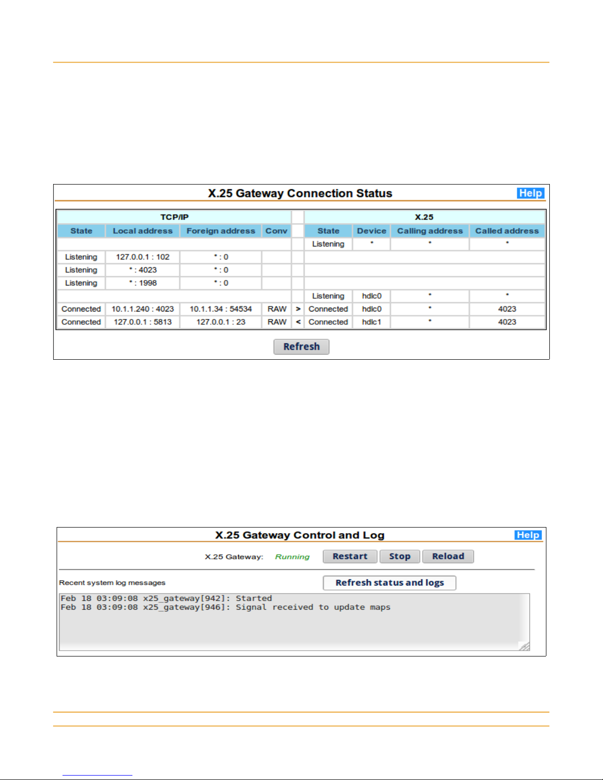
3.10.1 Connection Status
This page displays summary information about the interconnections between TCP sockets and X.25
logical channels. These interconnections result from connection requests being mapped by the routing
pages.
To view details specific to the X.25 logical channels, refer to the LCI Status page.
To view details specific to the TCP sessions, Telnet or ssh to the command interface. Once logged in,
the following Linux command may be used to view details:
netstat -ntp
Use the “-h” option to view additional command options.
3.10.2 Control & Log
This page displays the operational status of the X.25/TCP gateway application, and allows the
application to be stopped or started. The log section displays the history of the application since
startup, or last log file rotation.
www.microtronix.com 22
Page 23
Microtronix Access X.25–TCP/IP Gateway
3.11 Synchronous Server Configuration
A WAN port may be configured for raw synchronous HDLC operation by configuring it as a
Synchronous Server interface. Ensure that X.25 and Terminal server operation are disabled for the
selected port by selecting Status->Disable in the L1-Device page, and the Enabled button deselected in the Serial-TCP page.
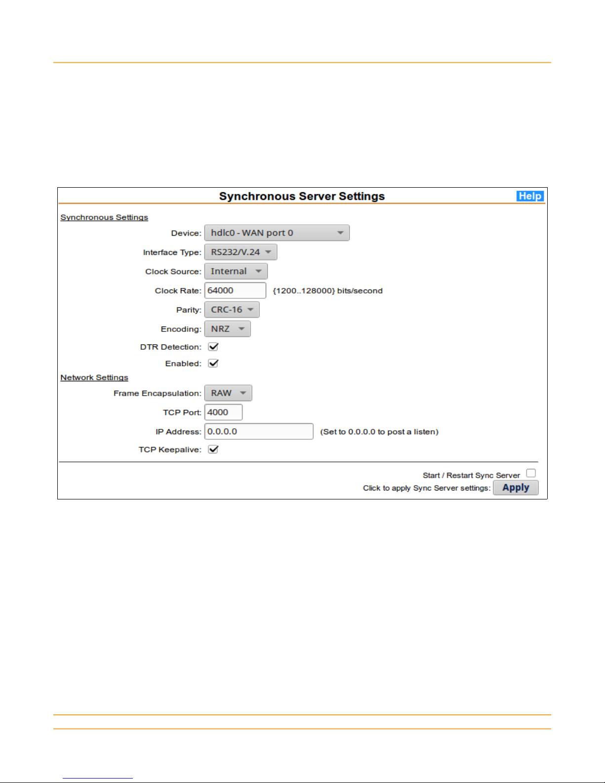
To configure a port for synchronous service, select Synchronous-TCP from the main menu Sync
Server section to display the configuration form:
3.11.1 Device Settings
1) Select the port from the Device drop-down list.
2) Configure the device settings to match the attached device.
3) If the device asserts a DTR signal, select DTR detection. This also controls TCP connectivity.
4) Click the Enabled checkbox.
3.11.2 Network Settings
5) Select the mode of operation from the drop-down list. RAW does not preserve frame
boundaries across the TCP/IP interface. MBIT will preserve frame boundaries when
transmitting over the TCP/IP interface.
6) Select the TCP port on which a listen is posted for remote clients, or to which a connection is to
be initiated towards a remote server.
www.microtronix.com 23
Page 24
Microtronix Access X.25–TCP/IP Gateway
7) Enter the remote IP address to which the connection will be made, or enter 0.0.0.0 for a listen to
be posted.
3.11.3 Update and Start the Server
8) Check the Start / Restart Sync Server box for changes to become active.
9) Click the Apply button to save changes and (re)start the server if requested.
For additional information, click the Help button on the page.
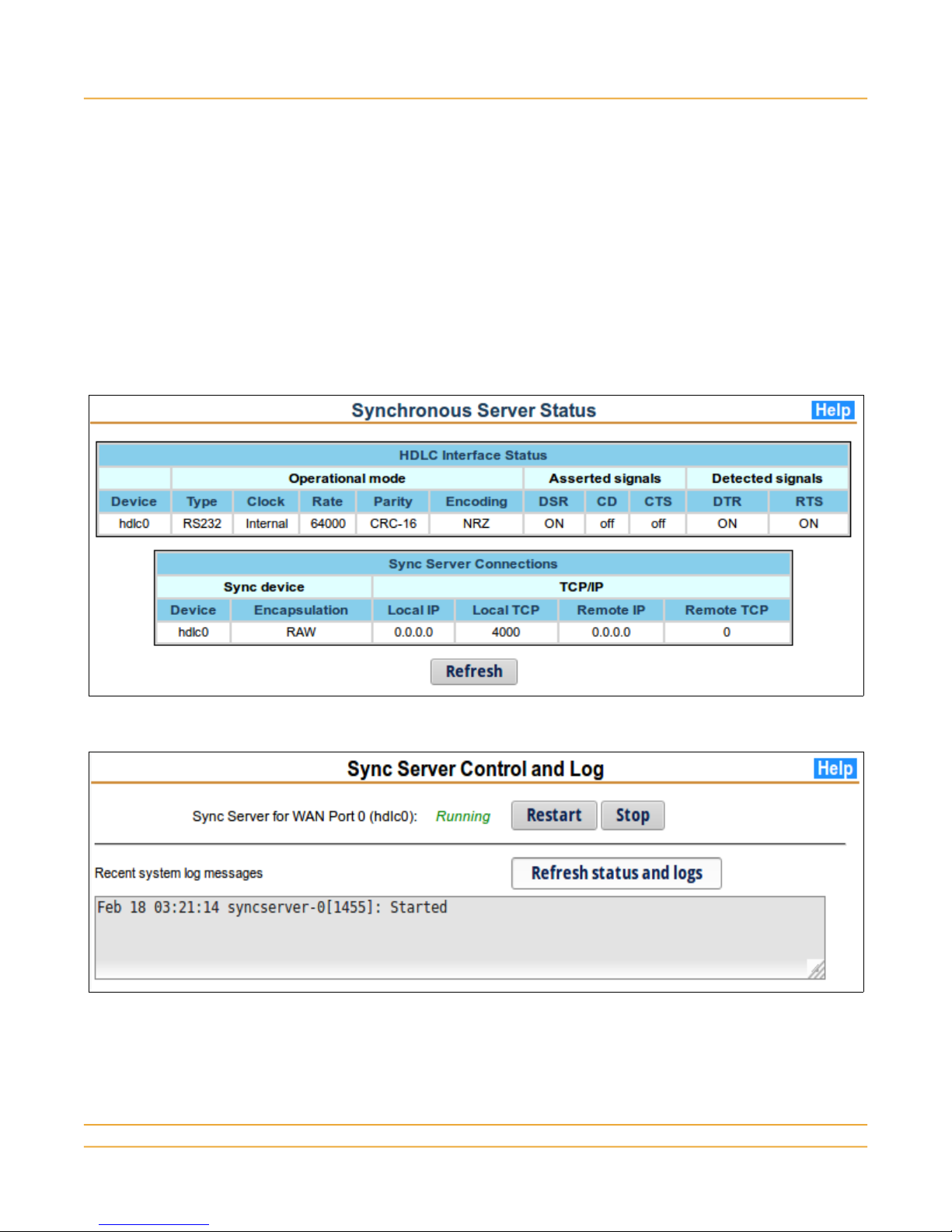
3.11.4 Verify Sync Server Connection
Click on the Status and Control & Log items in the Sync Server main menu section. Refer to the
Help pages for details.
www.microtronix.com 24
Page 25
Microtronix Access X.25–TCP/IP Gateway
3.12 Terminal Server Configuration
The Console, WAN, and external USB serial adapter ports may be configured for asynchronous serial
operation by configuring them as a terminal server interface. Ensure that X.25 and Synchronous
Server operation are disabled for the selected port by selecting Status->Disable in the L1-Device
page, and the Enabled button de-selected in the Synchronous-TCP page.
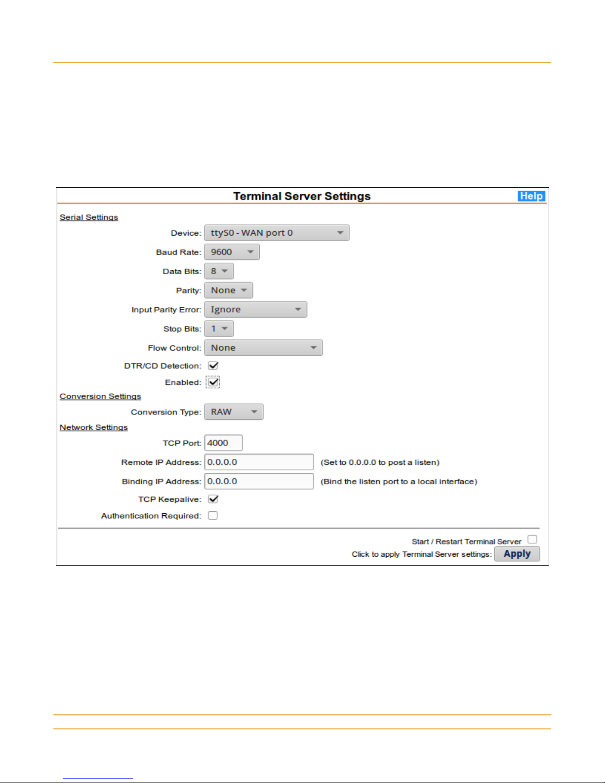
To configure a port for terminal service, select Serial-TCP from the main menu Terminal Server
section to display the configuration form.
3.12.1 Serial Settings
1) Select the port from the Device drop-down list.
2) Configure the device settings to match the attached device.
3) If the device asserts a DTR signal, select DTR detection. This also controls TCP connectivity.
4) Click the Enabled checkbox.
www.microtronix.com 25
Page 26

Microtronix Access X.25–TCP/IP Gateway
3.12.2 Conversion Settings
5) Select the mode of operation from the drop-down list. RAW treats data as a byte stream. LINE
does special line handling for data from TCP to the serial interface. IAC-ESC ensures data
transparency when connecting to remote Telnet sessions.
3.12.3 Network Settings
6) Select the TCP port on which a listen is posted for remote clients, or to which a connection is to
be initiated towards a remote server.
7) Enter the remote IP address to which the connection will be made, or enter 0.0.0.0 for a listen to
be posted.
8) Optional: Enter the IP address of the local interface on which the listen TCP port is to be bound.
For internal connections, 127.0.0.1.
9) Check the Authentication Required box if the remote client must login.
3.12.4 Update and Start the Server
9) Check the Start / Restart Terminal Server box for changes to become active.
10) Click the Apply button to save changes and (re)start the server if requested.
For additional information, click the Help button on the page.
www.microtronix.com 26
Page 27

Microtronix Access X.25–TCP/IP Gateway
3.12.5 Verify Terminal Server Connection
Click on the Status and Control & Log items in the Terminal Server main menu section. Refer to the
Help pages for details.
www.microtronix.com 27
Page 28

Microtronix Access X.25–TCP/IP Gateway
4 Cables
4.1 WAN Cables
When configured for sync (X.25), the DB25F WAN ports have an RS530 DCE pin configuration
(compatible with ISO 2110). RS232 is a subset of RS530, so a WAN port has a standard RS232 pin
assignment when configured for RS232/V.24.
4.1.1 Connecting to a DCE device
The following cables are used when connecting to DCE device (like a modem) with a female connector
that is supplying clocking on the DCE transmit and receive clock pins.
Crossover cable part numbers
W4025-V24-DTE DB25M-DB25M RS232 /V.24 crossover cable
W4025-V35-DTE DB25M-M34M V.35 crossover cable
W4025-X21-DTE DB25M-DB15M X.21 crossover cable
W4025-RS449-DTE DB25M-DB37M RS449/V.36 crossover cable
W4025-RS530-DTE DB25M-DB25M RS530 crossover cable
4.1.2 Connecting to a DTE device
The following cables are used when connecting to DTE device with a male connector that expects to
receive clocking on the DCE transmit and receive clock pins. If replacing a modem, avoid any modem
handshake issues by configuring the device's interface for “leased line” or “permanent modem” type
connection.
Straight through cable part numbers
811-SC6MF DB25MF RS232/V.24 straight through cable
W4025-V35-DCE DB25M-M34F V.35 straight through cable
W4025-X21-DCE DB25M-DB15F X.21 straight through cable
W4025-RS449-DCE DB25M-DB37F RS449/V.36 straight through cable
W4025-RS530-DCE DB25M-DB25F RS530 straight through cable
www.microtronix.com 28
Page 29

Microtronix Access X.25–TCP/IP Gateway
4.2 Serial and Console Cables
When configured for async serial, the DB25F WAN ports have an RS232 DCE pin configuration. On
models with a DB9 Console port, the port has a DB9F connector with RS232 DCE pin configuration.
4.2.1 Connecting to a DCE device
The following cables are used when connecting to a serial DCE device (like a modem) that has a DB25
or DB9 female connector.
Null modem cable part numbers
W4025-V24-DTE DB25M-DB25M - WAN port to DB25F
W4009-V24-DTE-S DB25M-DB9M - WAN port to DB9F
4.2.2 Connecting to a DTE device
The following cables are used when connecting to a serial DTE device (like a PC COM port) that has a
DB25 or DB9 male connector. If replacing a modem, avoid any modem handshake issues by
configuring the device's interface for “leased line” or “permanent modem” type connection.
Straight through cable part numbers
811-SC6MF DB25MF - WAN port to DB25M
[284-MC1MF DB25M-DB9F - WAN port to DB9M
www.microtronix.com 29
Page 30

Microtronix Access X.25–TCP/IP Gateway
5 Encapsulation Message Formats
The following are the formats of the messages used to encapsulate X.25 packet data over TCP
connections. The TCP/IP host is expected to implement one of these methods if message preservation
is required on the X.25 host.
Count (length) fields are in network byte order (big endian) with most significant byte first, least
significant byte last.
5.1 MBIT (2-byte count field)
Simple encapsulation of data using a 2-byte length field. Used to encapsulate and demarcate X.25
packet data. Each MBIT message contains the data from an X.25 packet with More bit set to zero, or
the concatenated data from a sequence of data packets with More bit set trailed by a data packet with
More bit clear. The purpose is to preserve the boundaries of application messages.
Count = x Payload (x bytes)
5.2 RFC1006 (ISO TP)
Encapsulation method to provide ISO Transport Service for bridging between X.25 and TCP hosts.
Preserves application message boundaries similar to MBIT above, and can be used as an alternative to
MBIT. The header is 4 bytes.
03 00 Count = 4+x Payload (x bytes)
5.3 Q-MBIT (extended RFC1006)
Identical to RFC1006, and also provides preservation of the Qualified bit (Q-bit) of data packets. This
method may be used whenever the X.25 application makes use of of Q-bit packets for control
information.
03 0 Q Count = 4+x Payload (x bytes)
5.4 XOT (RFC 1613 – X.25 Over TCP)
This method is used for encapsulation of the entire X.25 packet including control, data, and RR
packets. The payload is the entire X.25 packet including the 3-byte packet header. The count is the
payload length.
00 00 Count = x Payload (x bytes)
5.5 OFTP (RFC 5024)
Encapsulation method to provide bridging between X.25 and TCP hosts using ODETTE File Transfer
Protocol. Preserves application message boundaries by using a 4-byte Stream Transmission Header
on top of TCP to preserve X.25 M-bit sequences. Version (V) is 4 bits with value 1, Flags (F) is 4 bits
with value 0, and Length is 24 bits (3 bytes) in big endian (network) order.
V F Length = 4+x Payload (x bytes)
5.6 RBP (Cisco Record Boundary Preservation)
Encapsulation method to provide bridging between X.25 and TCP hosts. Preserves application
message boundaries similar to MBIT above, and can be used as an alternative to MBIT. The header is
www.microtronix.com 30
Page 31

Microtronix Access X.25–TCP/IP Gateway
6 bytes. The count ( 2 bytes network order) is the payload length. The flag is coded 0x00 to indicate a
complete application message, or coded as 0x01 to indicate a continuation of the application message
in subsequent RBP messages with the final fragment in an RBP message with flag 0x00.
D7 4A Count = x Flag 00 Payload (x bytes)
5.7 QRBP
RBP with Q-bit support. Identical to RBP above, except the flag can include value 0x02 to indicate an
X.25 Q-bit message.
D7 4A Count = x Flag 00 Payload (x bytes)
5.8 AEPN
Encapsulation method to provide bridging between X.25 and TCP hosts. Preserves application
message boundaries similar to MBIT above, and can be used as an alternative to MBIT. The header is
8 bytes. The count ( 2 bytes network order) is the payload length. The flag is coded 0x00 to indicate a
complete application message, or coded as 0x80 to indicate a continuation of the application message
in subsequent AEPN messages with the final fragment in an RBP message with flag 0x00.
X.25 Q-bits are preserved by use of the 0X40 bit in the flag field.
54 9F 08 02 Count = x Flag 00 Payload (x bytes)
www.microtronix.com 31
Page 32

6 Contact Microtronix
Microtronix Datacom Ltd.
4056 Meadowbrook Drive, Unit 126
London ON N6L 1E3
CANADA
Tel: +1 519 690-0091
Fax: +1 519 690-0092
General Inquiries: info@microtronix.com
Sales Enquiries: sales@microtronix.com
Customer Support: support@microtronix.com
Microtronix Access X.25–TCP/IP Gateway
www.microtronix.com 32
 Loading...