


User manual
005.006
User manual for the portable device
myDatasensH2S 1000
Rev. 03 valid from:
l Firmware version: 01v023
l Modem version: 01v026
l Server version: 37.1
l Hardware version: 1.7
Microtronics Engineering GmbH | www.microtronics.at
Hauptstrasse 7 | 3244 Ruprechtshofen | Austria
Tel +43 2756 77180 23 | Fax +43 2756 77180 33 | support@microtronics.at


Chapter 1 Table of contens
Chapter 1 Table of contens
User manual for the portable device myDatasensH2S 1000 1
Chapter 1 Table of contens 3
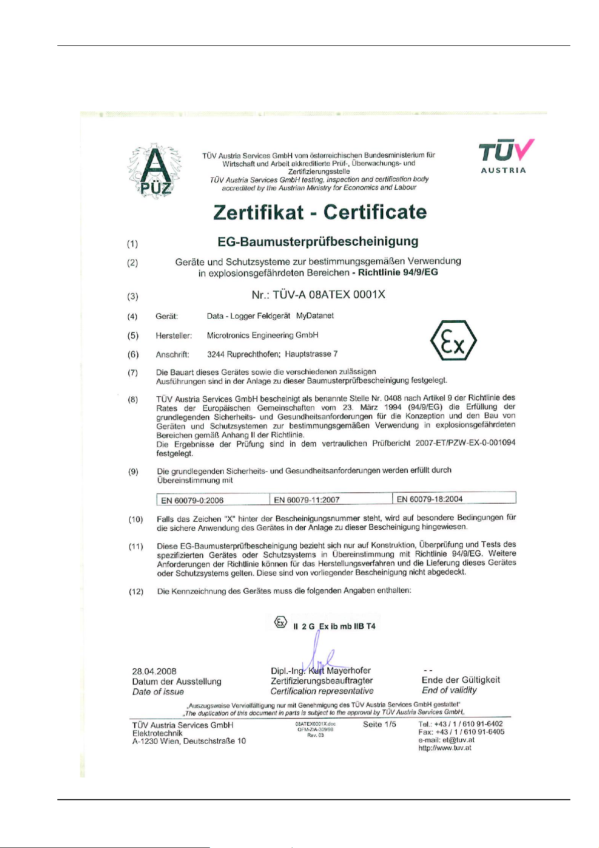
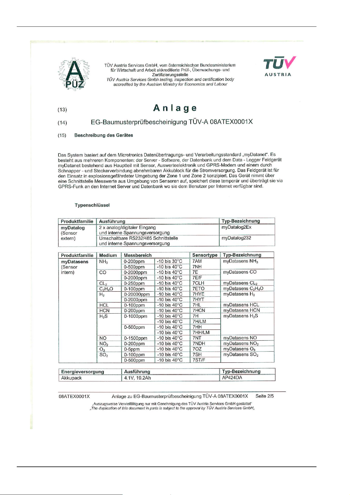
Chapter 2 Declaration of conformity 7
Chapter 3 Ex certification 9
Chapter 4 Technical data 11
Chapter 5 General specifications 13
5.1 Translation 13
5.2 Copyright 13
5.3 General descriptive names 13
5.4 Ex protection 13
5.5 Safety instructions 14
5.5.1 Use of the hazard warnings 14
5.5.2 Safety and preventative measures for handling GSM/GPRS modems 15
5.5.2.1 Safety and precautionary measures for the installation of the GSM/GPRS modem
15
5.5.2.2 Safety measures for installing the antenna 15
5.6 Overview 16
5.7 Intended use 16
5.8 General product information 17
5.9 Device labelling 17
5.10 Installation of spare and wear parts 18
5.11 Storage of the product 18
5.12 Obligation of the operator 19
Chapter 6 Functional Principle 21
6.1 ALOHA transmission mode 21
6.2 Determining the H2S concentration 21
6.2.1 Determining the raw value 22
6.2.2 Calculation of the calibrated H2S measurement value 22
Rev. 03 3

6.2.3 Calculation of the trimmed H2S measurement value 23
6.2.4 Digital filter 24
Chapter 7 Storage, delivery and transport 25
7.1 Inspection of incoming deliveries 25
7.2 Scope of supply 25
7.3 Storage 25
7.4 Transportation 26
7.5 Return 26
Chapter 8 Installation 27
8.1 Dimensions 27
8.2 Installing the myDatasensH2S 1000 27
8.2.1 Wall mounting 28
8.2.2 Suspended installation 30
8.3 Electrical installation 31
8.3.1 Connecting the GSM antenna 31
8.3.1.1 Optimum antenna positioning for assembly in a shaft 31
8.3.1.1.1 Influences on the signal quality 31
8.3.1.1.2 Possibilities for improving the signal quality 32
8.3.1.1.3 Procedure for determining the optimum position of the antenna 32
Chapter 9 Initial Start-Up 35
9.1 User information 35
9.2 General principles 35
9.3 Placing the system into operation 35
9.4 Testing communication with the device 36
Chapter 10 User interfaces 39
10.1 User interface on the myDatasensH2S 1000 39
10.1.1 Operating elements 39
10.1.1.1 Solenoid switch 39
10.1.1.2 Status LED 40
10.2 User interface on the myDataweb-Server 41
4 Rev. 03

Chapter 1 Table of contens
10.2.1 Site configuration 41
10.2.1.1 Site 41
10.2.1.2 Comments 41
10.2.1.3 Measurement channels 41
10.2.1.3.1 Basis 41
10.2.1.3.2 Alarms 42
10.2.1.3.3 Cross sensitivity of the H2S sensor 42
10.2.1.4 Calculated channels 42
10.2.1.4.1 Basis 42
10.2.1.4.2 Calculation 43
10.2.1.4.3 Alarm 44
10.2.1.5 Internal channels 44
10.2.1.5.1 Basis 44
10.2.1.5.2 Alarms 44
10.2.1.6 Alarm settings 45
10.2.1.7 Basic setting 46
10.2.1.8 FTP export settings 46
10.2.2 Device configuration 46
10.2.2.1 Comments 47
10.2.2.2 Measurement instrument 47
10.2.2.3 Device-specific settings 48
10.2.2.4 GPRS 48
Chapter 11 Maintenance 49
11.1 General maintenance 49
11.2 Accu or battery pack 49
11.3 Replacing the accu or battery pack 49
11.3.1 Charging the accu pack 52
11.3.2 Replacing the accu cover 54
11.3.3 Maintenance of the accu seal 55
11.4 Maintenance of the antenna socket 57
Rev. 03 5

11.5 Maintenance of the antenna connector 57
11.6 Calibration, trimming and zero-point alignment 58
11.6.1 Safety instructions for handling H2S gas 59
11.6.2 Calibration 59
11.6.2.1 Calibration specifications 60
11.6.2.2 Calibration room equipment 60
11.6.2.3 Calibration process 60
11.6.3 Trimming 64
11.6.4 Zero-point alignment 68
Chapter 12 Removal/disposal 71
Chapter 13 Troubleshooting and repair 73
13.1 General problems 73
13.2 Log entries and error codes 74
13.2.1 Modem error 76
13.3 Evaluating the device log 79
13.3.1 Evaluating the device log on the myDataweb server 79
13.3.2 Evaluating the device log using myDatanetDeviceConfig 79
Chapter 14 Spare parts and accessories 81
14.1 Assembly sets 81
14.2 Antennas 81
14.3 Accu and battery packs 81
14.4 Charging device 81
14.5 Cable 82
14.6 Other accessories 82
Chapter 15 Document history 83
Chapter 16 Contact information 85
6 Rev. 03

Chapter 2 Declaration of conformity
Chapter 2 Declaration of conformity
Rev. 03 7

Chapter 3 Ex certification
Chapter 3 Ex certification
Rev. 03 9
10 Rev. 03

Chapter 4 Technical data
Chapter 4 Technical data
Voltage
supply
Housing Material: Noryl GTX 973
Ex
certification
Operating
temperature
Storage
temperature
Display LED for indicating the operating mode and error codes
Operation Solenoid switch for initiating ALOHA transmission mode
USB
interface
Battery pack BP457A : 51Ah
Accu pack AP424DA : 19,2Ah
Weight: 450g (without accu or battery pack)
Protection class: IP66
Dimensions (WHD): 100x240x100mm(without antenna)
II 2 G Ex ib IIB T4 Gb
-10...+40°C, 15...90%rH non-condensing
-20...+70°C (without accu or battery pack)
1 x USB slave for establishing a connection to a PC. The myDatanetDeviceConfig
configuration program must be installed on the PC to enable communication with
the myDatasensH2S 1000 .
Antenna
connection
H2S sensor Measurement range: 0-200ppm
Temperature
sensor
Data
memory
Data type s16 (16 signed)
Data
transmission
FME-M
Max. overflow: 1000ppm
Resolution: 0,25ppm
Pressure range: Atmospheric +/-10%
T90response time: <=35s
Calibration cycle: 6 months
Max. service life: 2 years
Repeat accuracy: 1%
Measurement range: -10...+40°C
Internal flash memory for up to 125.700 measurement values
By means of GSM/GPRS quad-band modem to the relevant myDataweb server
SIM The myDatasensH2S 1000 is equipped with an integrated SIM card.
Rev. 03 11

Monthly
data volume
3,88MB for two-minute measurement cycle and 120-minute transmission cycle
Device
operating
time
Battery pack BP457A :
l Approx. 2 years with two-minute measurement cycle and 120-minute
transmission cycle
l Approx. 2,2 years with five-minute measurement cycle and 120-minute
transmission cycle
l Approx. 4 years with five-minute measurement cycle and 480-minute
transmission cycle
Accu pack AP424DA :
l Approx. 0,9 years with two-minute measurement cycle and 120-minute
transmission cycle
l Approx. 1 year with five-minute measurement cycle and 120-minute
transmission cycle
l Approx. 2 years with five-minute measurement cycle and 480-minute
transmission cycle
12 Rev. 03

Chapter 5 General specifications
Chapter 5 General specifications
The information in this manual has been compiled with great care and to the best of our knowledge.
The manufacturer, however, assumes no liability for any incorrect specifications that may be
provided in this manual. The manufacturer is not responsible for direct, indirect, accidental or
consequential damages which arise from errors or omissions in this manual even if advised of the
possibility of such damages. In the interest of continuous product development, the manufacturer
reserves the right to make improvements to this manual and the products described in it at any time
and without prior notification or obligation.
Note: The specifications in this manual are valid as of the versions listed on the front page. Revised versions of this
manual, as well as software and driver updates are available in the service area of the myDataweb server.
5.1 Translation
For deliveries to countries in the European Economic Area, the manual must be translated into the
language of the respective country. If there are any discrepancies in the translated text, the original
manual (German) must be referenced or the manufacturer contacted for clarification.
5.2 Copyright
The copying and distribution of this document as well as the utilisation and communication of its
contents to others without express authorisation is prohibited. Contraventions are liable to
compensation. All rights reserved.
5.3 General descriptive names
The use of general descriptive names, trade names, trademarks and the like in this manual does not
entitle the reader to assume they may be used freely by everyone. They are often protected
registered trademarks even if not marked as such.
5.4 Ex protection
The portable device myDatasensH2S 1000 is designed for use in areas with an explosive
atmosphere in Zone1. The accu pack can be replaced in the Ex area but must not be charged. Please
note that if the seal is broken on devices with a maintenance contract, this will render the contract
void. Outside the Ex area, the accu pack must only be charged with the charging device tested and
approved by the manufacturer. The power supply in the Ex area must only be provided by the
designated, intrinsically safe accu or battery packs. The USB interface must NOT be used in the Ex
area.
II 2 G Ex ib IIB T4 Gb
Rev. 03 13

Important note: The Ex approval is only valid if the corresponding marking is provided on
the type plate of the measurement device.
Important note: The certificates of conformity and any relevant test certificates from the
respective authorities must be carefully observed during installation and commissioning.
1 myDatasensH2S 1000
5.5 Safety instructions
For the connection, commissioning and operation of the myDatasensH2S 1000 , the following
information and higher legal regulations of the country (e.g. ÖVE), such as valid EX regulations as
well as the applicable safety and accident prevention regulations for the respective application case
must be observed.
Please read this manual completely before unpacking, setting up or operating this device. Observe
all hazard, danger and warning information. Non-observance can lead to serious injuries to the
operator and/or damage to the device.
Ensure that the safety equipment of this measurement device is not impaired. Install and use the
measuring system only in the manner and method described in this manual.
Important note: The manufacturer's products that are designed for use outdoors include
extensive protection against penetrating moisture and dust.
5.5.1 Use of the hazard warnings
DANGER:
Indicates a potential or threatening hazardous situation that will result in death or serious
injuries if not avoided.
WARNING:
Indicates a potential or threatening hazardous situation that can result in death or serious
injuries if not avoided.
CAUTION:
Indicates a potential hazardous situation that can result in minor or moderate injury.
Note: Indicates a situation that does not result in any injury to persons.
14 Rev. 03

Chapter 5 General specifications
Important note: Indicates a situation that can result in damages to this instrument if it is not
avoided. Information that must be particularly emphasised.
Note: Information that supplements the specifications in the main text.
5.5.2 Safety and preventative measures for handling GSM/GPRS modems
Observe the following safety and preventative measures during all phases of installation, operation,
maintenance or repair of a GSM/GPRS modem. The manufacturer shall not be held liable if the
customer disregards these preventative measures.
CAUTION:
The GSM/GPRS modem connection may not be used in hazardous environments.
No guarantee of any kind, whether implicit or explicit, is given by the manufacturer and its
suppliers for the use with high risk activities.
In addition to the following safety considerations, all directives of the country in which the device is
installed must be complied with.
Important note: No liability shall be assumed at any time and under no condition for the
connection via a GSM/GPRS modem for whose use radio signals and networks are utilized,
The GSM/GPRS modem must be switched on and be operated in an area where sufficient
signal strength is present.
5.5.2.1 Safety and precautionary measures for the installation of the GSM/GPRS modem
l This device must only be installed by a trained technician who applies the recognised
installation practices for a radio frequency transmitter including the correct grounding of
external antennas.
l The device must not be operated in hospitals and/or in the vicinity of medical equipment such
as heart pacemakers or hearing aids.
l The device must not be subjected to strong vibrations or impacts.
l The GSM/GPRS modem can cause interferences if it is in the vicinity of television sets, radios
or computers.
l Do not open the GSM/GPRS modem. Any modification to the equipment is prohibited and will
result in the operating licence being revoked.
l The use of GSM services (SMS messages/data communication/GPRS, etc.) may lead to
additional costs. The user alone is responsible for any resulting damages and costs.
l Do not install the device in any other way to the one described in the operating instructions.
Improper use will invalidate the warranty.
5.5.2.2 Safety measures for installing the antenna
l Only use antennas that are recommended or supplied by the manufacturer.
l The antenna must be installed at a distance of at least 20cm from individuals.
l The antenna must not be extended outside protected buildings and must be protected against
lightning strikes.
Rev. 03 15

5.6 Overview
Bottom of the myDatasensH2S 1000
1 H2S sensor 4 Solenoid switch
2 USB interface 5 Status LED
3 Supply connector 6 Antenna connection
Top of the myDatasensH2S 1000
(view without accu or battery pack)
5.7 Intended use
The portable measurement instrument is used to record H2S concentrations. The device is batteryoperated. The measured and recorded data is stored on a non-volatile memory medium. This stored
data is sent to a central server for further processing via the mobile network. The device is equipped
with an integrated SIM card. The maximum permissible limit values set out in chapter "Technical
data" on page 11 must be observed. The manufacturer shall not be liable for any operational cases
that deviate from these limit values and have not been approved by the manufacturer in writing.
Note: This device is exclusively intended to be used for the purposes as described above.
Any other use or use beyond what is specified or a modification of the device shall be
deemed to be not for the intended purpose and is not permitted without the express written
consent of the manufacturer. The manufacturer shall not be held liable for any damages that
may result from such unauthorised use or modification. The operator alone bears the
associated risk.
Note: The manufacturer is not liable for data loss of any kind if the device is damaged and
data is not able to be stored correctly.
16 Rev. 03

Chapter 5 General specifications
Note: The integrated SIM chip provides a mobile communications connection to a variety of
international service providers. In order to be able to utilise all functions of the device, you
must ensure that the device is located in the service area of one of these service providers.
You can find a list of all supported countries and associated service providers under
www.microtronics.at/footprint. A Managed Service contract with Microtronics Engineering
GmbH is required for use of the mobile data transmission (see
www.microtronics.at/managedservice). This includes the provisioning of the mobile
communications connection via the network of the service provider included in the abovementioned list.
5.8 General product information
The device is a compact, portable device for recording and transmitting H2S concentrations. The
device is equipped with an integrated sensor for this purpose. In addition to the H2S concentration,
the internal measurement values "Battery", "GSM level" and "Int. temp" are determined (see
"Internal channels" on page 44). All of the generated measurement data is temporarily saved on an
internal data memory and is then wirelessly transmitted to a central location at freely selected
intervals. The device is also configured via this connection. The device is equipped with an
integrated SIM chip.
5.9 Device labelling
The specifications in this user manual apply exclusively to the myDatasensH2S 1000 device type.
The type plate is located on the rear side of the device and includes the following specifications:
l Type designation
l Serial number
l CE marking
l Protection class
l Environmental conditions during operation
l Ex protection label as specified in chapter "Declaration of conformity" on page 7
l Hardware revision
It is important that the correct type designation and serial number is specified for all queries and
spare part orders. Only then can we process requests promptly and properly.
Type plate myDatasensH2S 1000
Rev. 03 17

Note: These operating instructions are part of the device and must be available to the user at
all times. The safety instructions included therein must be observed.
DANGER:
It is strictly prohibited to disable the safety equipment or modify its mode of operation.
5.10 Installation of spare and wear parts
Please be advised that spare and accessory parts that have not been supplied by the manufacturer
have also not been inspected or approved by the manufacturer. The installation and/or use of such
products can possibly have a negative impact on the specified constructional properties of the
device. The manufacturer shall not be liable for any damages that arise from the use of non-original
parts and non-original accessory parts.
Note: The use of spare and wear parts that are not approved by the manufacturer shall void
the Ex approval.
5.11 Storage of the product
To store the myDatasensH2S 1000 , activate the transport lock, by deactivating the "Measurement"
and "Transmission" in the input screen of the myDataweb server to configure the device (see
"Device-specific settings" on page 48). Then activate the ALOHA transmission mode (see "ALOHA
transmission mode" on page 21) via the solenoid contact so that the amended configuration is
transmitted to the myDatasensH2S 1000 . During this process, all of the data that has not yet been
transferred to the myDataweb server is transmitted. The antenna can be removed as soon as the
GPRS connection has been deactivated - indicated by the status LED going out (see "Status LED" on
page 40). Store the myDatasensH2S 1000 in its original packaging. During storage the accu or
battery pack should not be disconnected from the device and the protective armour should also not
be removed.
By activating the transport lock, the myDatasensH2S 1000 is in a very energy-saving mode. However,
it may still occur that the accu or battery pack is fully discharged if the device is stored for very long
periods. Although the configuration and the most recent determined data are definitely maintained.
The transport lock is deactivated again by re-initiating the ALOHA transmission mode (see "ALOHA
transmission mode" on page 21) and the myDatasensH2S 1000 resumes operation according to the
configuration.
18 Rev. 03

Chapter 5 General specifications
5.12 Obligation of the operator
WARNING:
In the EEA (European Economic Area), the national implementation of the framework
directive (89/391/EEC) as well as the associated specific directives and from these in
particular, the directive (89/655/EEC) about the minimum safety and health requirements for
use of work equipment by workers at work, each in their respective version are to be
complied with.
The operator must obtain the local operating licence and the associated documents.
In addition, the operator must comply with the local legal requirements for
l the safety of the personnel (accident prevention measures)
l the safety of the equipment (protective equipment and maintenance)
l the product disposal (waste disposal law)
l the material disposal (waste disposal law)
l the cleaning (cleaning agents and disposal)
l and the environmental protection amendments.
Before commissioning, the operator must ensure that the installation and commissioning –
provided these were performed by the operator himself – are in compliance with the local
regulations.
Rev. 03 19


Chapter 6 Functional Principle
Chapter 6 Functional Principle
6.1 ALOHA transmission mode
The ALOHA transmission mode is a special connection mode during which the myDatasensH2S 1000
establishes a 10-minute connection with the myDataweb server.
Initiating ALOHA transmission mode:
l Directly on the device using the solenoid switch (see "Solenoid switch" on page 39)
A speech bubble in the measurement device list (see "myDataweb-Server user manual" 005.002)
with the title "Aloha" indicates that a device is in ALOHA transmission mode.
Clicking on the speech bubble with the "Aloha" title opens the ALOHA data window (see "myDataweb-Server user manual" 005.002), which comprises the internal "Battery" and "GSM level" measurement values. The measurement values for the last thirty minutes are always shown in the ALOHA
data window, this can mean that data from a previous ALOHA transmission is included. The ALOHA
data is generated every three seconds independently of the normal measurement values and is thus
not saved with the standard measurement data.
6.2 Determining the H2S concentration
Diagram of how the "Gas" measurement value is generated (see "Measurement channels " on page 41)
1 Determining the raw value by means of aver-
aging (see "Determining the raw value" on
page 22)
3 Conversion of the calibrated H2S meas-
urement value to the trimmed H2S measurement value (see "Calculation of the
trimmed H2S measurement value" on page
23)
2 Conversion of the raw value to the calibrated
H2S measurement value (see "Calculation of
the calibrated H2S measurement value" on
page 22)
Rev. 03 21
4 Digital filter to prevent a measurement value
from drifting (see"Digital filter" on page 24)
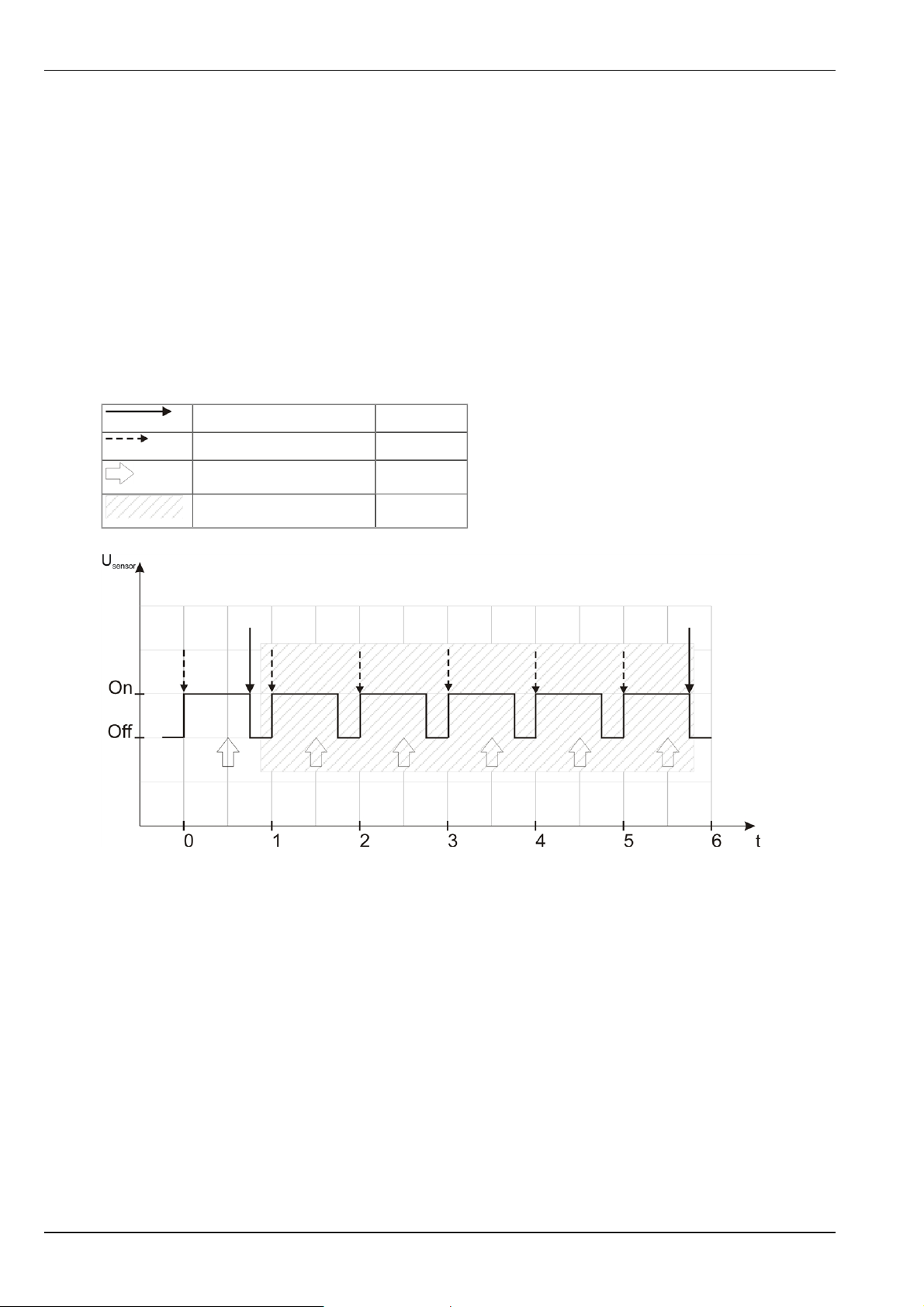
6.2.1 Determining the raw value
The supply to the gas sensor is activated once the sampling cycle (60 sec.) has expired. Following
expiry of the warm-up time (30 sec. ), 15 macro measurements are completed at intervals of 200ms
from which an average value is determined (sample measurement value). If the recording cycle is
longer than the sampling cycle, the sample measurement values generated from the 15 macro measurements are averaged over the measurement cycle. The raw value is then determined from this second averaging calculation.
Note:
Example for explaining how the raw value is determined
Recording cycle 5 min.
Sampling cycle 1 min.
Macro measurements 15 x 200ms
Averaging
Determining the raw value by means of averaging
Note: The customer cannot individually adjust the warm-up time for each device. However, there is an option to
select a server-wide setting that deviates from the standard value (30 sec. ). If a warm-up time is used that is
longer than the sampling cycle (60 sec.), the supply of the gas sensor is permanently activated.
For more detailed information, contact your responsible sales partner.
6.2.2 Calculation of the calibrated H2S measurement value
The raw value determined during the previous step is converted into the H2S measurement value by
means of the slope and offset determined during the calibration (see "Calibration process" on page
60).
22 Rev. 03

Min. raw value A
Max. raw value B
End of the measuring range C
Start of the measuring range D
Raw value E
Chapter 6 Functional Principle
Corresponding H2S measurement value for
the raw value
Slope determined during the calibration
(see "Calibration process" on page 60)
Offset determined during the calibration
(see "Calibration process" on page 60)
k
Calib
d
F
Calib
F = k
Calib
* E + d
Calib
6.2.3 Calculation of the trimmed H2S measurement value
The calibrated H2S measurement value determined during the previous step can also be slightly
adjusted (trimmed) during this step. For this purpose, the determined slope and offset are used for
the trimming process (see "Trimming" on page 64). This step can be deactivated via myDatanetDeviceConfig . The zero-point alignment does not change the slope (see "Zero-point alignment" on page 68), although the offset is set. In any case, this slope and offset are independent of
those determined during the calibration. The basic calibration of the device is not changed by the
trimming process or zero-point alignment.
Min. calibrated H2S measurement value A
Max. calibrated H2S measurement value B
Min. trimmed H2S measurement value C
Max. trimmed H2S measurement value D
Calibrated H2S measurement value E
Calibrated H2S measurement value
assigned to the trimmed H2S measurement
value
F
Rev. 03 23

Slope determined during trimming process (see "Trimming" on page 64)
k
Trim
Offset determined during trimming proc-
d
Trim
ess (see "Trimming" on page 64)
F = k
Trim
* E + d
Trim
6.2.4 Digital filter
If the H2S measurement value changes by more than 0,8ppm in comparison to the previous one,
the new value is adopted in full. If the changes are below 0,32ppm , only 0,5% of the new H2S
measurement value is included in the result. Between 0,32ppm and 0,8ppm , the impact of the new
H2S measurement value is linearly interpolated between 0,5% and 100%.
24 Rev. 03

Chapter 7 Storage, delivery and transport
Chapter 7 Storage, delivery and transport
7.1 Inspection of incoming deliveries
Please check the shipment immediately after receiving for completeness and intactness. Immediately report any discovered transport damages to the delivering carrier. Also notify the manufacturer in writing about this without delay. Report any incompleteness in the delivery to the
responsible representative or directly to the company headquarters of the manufacturer within 2
weeks (see "Contact information" on page 85).
Note: Any claims received thereafter will not be acknowledged!
7.2 Scope of supply
Note: The accu or battery pack required for operation is not part of the standard scope of
delivery and must be ordered separately (see "Accu and battery packs" on page 81).
The standard scope of delivery of the myDatasensH2S 1000 (206.101 ) includes:
l myDatasensH2S 1000
l Antenna 900 FME (206.801)
l Extension cable for Antenna 900 FME (206.805)
l USB15AB (206.601)
l MDN Magnet (206.803)
l MDN Protection casing (206.320)
l myDatanet Service Kit (206.324 )
l Quick Guide(005.202)
Additional equipment such as assembly sets, antennas, accu or battery pack, charger, etc., depend
on the order. Please check this against the delivery slip.
7.3 Storage
The following storage conditions must be observed:
myDatasensH2S 1000 Storage temperature -20...+70°C
Humidity 15...90%rH non-condensing
BP457A Operating temperature -10...+40°C
Storage temperature 0...+30°C
AP424DA Operating temperature -10...+40°C
Charging temperature 0 ...+40°C
Storage temperature 0...+30°C
Humidity 15...90%rH
Rev. 03 25

Note: The table above only includes the storage conditions for the two energy sources used most frequently for the
myDatasensH2S 1000 . Please consult the appropriate factsheet for information about the storage conditions of
other accu or battery packs.
Important note: The storage conditions included in the table only apply when the myDatasensH2S 1000 is disconnected from the accu or battery pack. This must not be completed
on devices with a maintenance contract (see "Warranty seal" on page 49) as the seal would
be broken during this process, rendering the maintenance contract invalid. For these devices
the same conditions apply to operation and storage.
Store the measurement technology so that it is protected against corrosive or organic solvent
vapours, radioactive emissions and strong electromagnetic radiation.
7.4 Transportation
The myDatasensH2S 1000 is designed for rough industrial applications. Nevertheless, it should not
be subjected to heavy shocks, bumps, impacts or vibrations. The original packaging must always be
used for transport.
7.5 Return
Every return must be accompanied by a fully field-out return form. This return form is available in
the service area of the myDataweb-Server. An RMA number is mandatory for any returns and can be
obtained from the Support & Service Centre (see "Contact information" on page 85). The return
shipment of the myDatasensH2S 1000 must occur in the original packaging and with freight and
insurance paid to Microtronics Engineering GmbH (see "Contact information" on page 85). Insufficiently cleared return shipments will otherwise not be accepted!
26 Rev. 03

Chapter 8 Installation
Important note: To prevent any damage to the device, the work described in this section of
the instructions must only be performed by qualified personnel.
8.1 Dimensions
Chapter 8 Installation
Dimensions: Height
(View with accu or battery pack and protective armour)
Dimensions: Width and depth
(View with accu or battery pack and protective armour)
8.2 Installing the myDatasensH2S 1000
Important note:
l
Ensure installation is completed correctly.
l
Comply with the existing legal and/or operational directives.
l
Improper handling can cause injuries and/or damage to the devices.
l
The myDatasensH2S 1000 must not be operated in the field without a protective
armour.
Rev. 03 27

l
Due to the electrostatic effects, the protective armour must not be rubbed with cloths
in the Ex zone.
The installation site must be selected according to specific criteria. The following conditions must be
avoided in any case:
l Direct sunlight
l Objects that radiate intense heat (maximum ambient temperature: -10...+40°C)
l Objects with a strong electromagnetic field (frequency converter or similar)
l Corrosive chemicals or gases (with the exception of H2S that is to be measured)
l Mechanical impacts
l Direct installation on paths or roads
l Vibrations
l Radioactive emissions
Note: Leave sufficient space at the upper end to mount the antenna. The space required depends on the antenna
used. Approx. 15cm of space must be left beneath the device. Further information about the installation
dimensions can be found in the relevant sub-chapter.
8.2.1 Wall mounting
The optional "MDN wall mounting (206.321 )" equipment is required for wall mounting.
Wall mounting - step 1 Wall mounting - step 2
28 Rev. 03

Chapter 8 Installation
1 Retaining bracket (included in the scope of
delivery of 206.321 )
2 Raised head tapping screw 4x40 (included in
the scope of delivery of 206.321 )
1. Drilling the holes for the assembly:
If you want to use the tapping screws (2) included in the equipment set to secure the
retaining bracket (1) to the wall, drill four 6-mm holes in the wall using the drill template as
a guide in accordance with the dimensions in the Figure "Wall mounting - step 1" on page
28.
If you want to use your own fastening screws you can use the drill guide provided in the
equipment set to determine the position of the holes. The diameters are then determined
by the screws that are being used and any wall plugs that may be required.
2. Securing the retaining bracket to the wall:
If you want to use the tapping screws (2) included in the equipment set, first of all insert
the supplied wall plugs into each of the four drill holes before screwing the retaining
bracket (1) to the wall (see "Wall mounting - step 1" on page 28).
3 myDatasensH2S 1000
If you are using your own screws, you must also insert the wall plugs into the holes before
screwing the retaining bracket (1) to the wall (see "Wall mounting - step 1" on page 28).
3. Carefully bend the brackets on the retaining bracket (1) apart and insert the myDatasensH2S
1000 in accordance with the Figure "Wall mounting - step 2" on page 28. The rear of the
myDatasensH2S 1000 (the side with the cut-out in the protective cover) must be facing the
wall.
Rev. 03 29

8.2.2 Suspended installation
The optional "Niro shackle (206.325)" equipment is required for suspended installations.
Suspended installation Detailed view of a suspended installation
1 Niro shackle (206.325) 2 myDatasensH2S 1000
1. Use the Niro shackle (206.325), to attach the myDatasensH2S 1000 to a rung of the channel
ladder or a similar fastening point in accordance with the figure "Detailed view of a
suspended installation " on page 30.
30 Rev. 03

Chapter 8 Installation
8.3 Electrical installation
Important note: Only qualified personnel should undertake the installation described in this
chapter of the operating instructions to avoid any damage to the device.
8.3.1 Connecting the GSM antenna
Important note: To ensure the correct functionality, only use antennas that are supplied by
the manufacturer. Using antennas and antenna extensions that are not listed in chapter
"Antennas" on page 81 will invalidate the Ex approval.
The standard antenna is directly attached to the antenna connector (see "Overview" on page 16) of
the myDatasensH2S 1000 .
If the distance between the antenna position and the myDatasensH2S 1000 is too great, you can use
a 5m Extension cable for Antenna 900 FME (206.805).
1. If you need an antenna extension, connect this to the antenna first.
2. Connect the antenna extension or antenna directly to the antenna connection of the
myDatasensH2S 1000 (see "Overview" on page 16).
Important note: Do not apply too much force when tightening the antenna. Tighten the
antenna or antenna extension with your hand. Do not use a tool except for the plastic
open-ended spanner that is included in the myDatanet Service Kit (206.324 ) that will
break if the applied force is too strong.
The following step is not mandatory.
3. Check whether the connection to the myDataweb has worked correctly (see "Testing
communication with the device" on page 36).
8.3.1.1 Optimum antenna positioning for assembly in a shaft
8.3.1.1.1 Influences on the signal quality
Signal losses compared to the reference measurement
Steel cover up to -30dBm
Concrete cover approx. -10dBm
Environmental influences up to -15dBm
Installation height of the antenna approx. -5dBm/depth of 15cm
Vertical/horizontal alignment approx. -10dBm
Horizontal alignment up to -15dBm
Centre/edge of the shaft approx. -10dBm
Other influences Transmission power of the network operator
Rev. 03 31

Note: Practical example:
GSM level Position
-67dBm Reference measurement outside the shaft
-103 dBm Measurement at a depth of 1.20m
-95dBm Vertically on the edge of the shaft at a depth of approx. 15cm
-83dBm Centre of the shaft, horizontal on the steel fitting
-89dBm Antenna turned by 90°
-78dBm Centre of the shaft, vertical
-75dBm Plastic pipe used instead of steel fitting
8.3.1.1.2 Possibilities for improving the signal quality
l Drill a duct for the antenna into the concrete ring on the shaft to bypass the steel cover
l Insert the antenna extension in an existing ventilation or supply pipe
l Use special types of antennas (please note: The use of antennas that are not approved by the
manufacturer with devices that are Ex approved will render this approval invalid)
8.3.1.1.3 Procedure for determining the optimum position of the antenna
1. Install the myDatasensH2S 1000 as described in chapter "Installing the myDatasensH2S 1000
" on page 27. During this process, also observe the notes regarding the influences on the
signal quality (see "Influences on the signal quality" on page 31).
Note: Have a Extension cable for Antenna 900 FME (206.805) at your disposal just in case.
2. Initiate the ALOHA transmission mode (see "ALOHA transmission mode" on page 21).
3. Wait until it is indicated in the list of measurement instruments that the device is in ALOHA
transmission mode. This is indicated by a speech bubble with the "Aloha" inscription.
4. Check the internal "GSM level" measurement value in the incoming data in the ALOHA data
window of the myDataweb server, which can be accessed by clicking on the speech bubble
with the "Aloha" inscription (see "myDataweb-Server user manual" 005.002). Change the
position of the antenna to obtain the best possible signal quality.
Note: A security stock of 15dBm is highly recommended.
32 Rev. 03

Note: Additional explanation about evaluating the "GSM level":
"GSM level"
>-64dBm
-64 to -73dBm
-74 to -83dBm
-84 to -93dBm
-94 to -107dBm
<= -108dBm
Chapter 8 Installation
Rev. 03 33


Chapter 9 Initial Start-Up
Chapter 9 Initial Start-Up
9.1 User information
Before you connect the myDatasensH2S 1000 and place it into operation, you must observe and
comply with the following user information!
This manual contains all information that is required for using the device.
Is intended for technically qualified personnel who have the relevant knowledge and experience in
the area of measurement technology.
Read this manual carefully and completely in order to ensure the proper functioning of the myDatasensH2S 1000 .
Please contact our technical department if anything is unclear or if you encounter difficulties with
regard to installation, connection or configuration (see "Contact information" on page 85).
If necessary, please also refer to the manuals of the accessory parts when commissioning the complete system. These manuals are included in the scope of delivery of the accessory parts.
9.2 General principles
The entire measurement system may only be placed into operation after completion and inspection
of the installation. Study the manual thoroughly before placing into operation to prevent faulty or
incorrect configuration.
Utilise the manual to familiarise yourself with the operation of the myDatasensH2S 1000 and the
input screens of the myDataweb-Server before you begin with the configuration.
9.3 Placing the system into operation
Note: It is recommended that the myDatasensH2S 1000 is first placed into operation in the office before moving the
device to the place of use. During this process, you should set a site for the later operation on the myDataweb
server (see "myDataweb-Server user manual" 005.002) and determine a site configuration (see "Site configuration" on page 41). Take the opportunity to get to know the functions of the device in a stable environment.
1. The myDatasensH2S 1000 is supplied with the transport lock activated (measurement and
transmission "OFF") and should also always be stored in this state (see "Storage of the product" on page 18). The transport lock is deactivated by initiating the ALOHA transmission mode
(see "ALOHA transmission mode" on page 21), whereby the first connection to the myDataweb
server is established.
2. Create a site for the operation on the myDataweb server (see "myDataweb-Server user
manual" 005.002).
Rev. 03 35

3. Configure the created site according to your requirements (see "Site configuration" on page
41).
4. Link the myDatasensH2S 1000 with the created site (see "Site" on page 41).
5. Activate the ALOHA transmission mode (see "ALOHA transmission mode" on page 21) so that
the site configuration is transmitted to the myDatasensH2S 1000 .
9.4 Testing communication with the device
1. Create a site for the operation on the myDataweb server (see "myDataweb-Server user
manual" 005.002).
2. Configure the created site according to your requirements (see "Site configuration" on page
41).
3. Link the myDatasensH2S 1000 with the created site (see "Site" on page 41).
4. Initiate the ALOHA transmission mode (see "ALOHA transmission mode" on page 21) so that
the configuration of the site is transmitted to the myDatasensH2S 1000 .
5. Wait until the list of measurement instruments indicates that the device is in ALOHA transmission mode. This is indicated by a speech bubble with the "Aloha" inscription.
6. Check the incoming data in the ALOHA data window of the myDataweb server, which can be
accessed by clicking on the speech bubble with the "Aloha" inscription (see "myDatawebServer user manual" 005.002). Particular attention must be paid to the internal "GSM level"
and "battery" measurement values.
36 Rev. 03
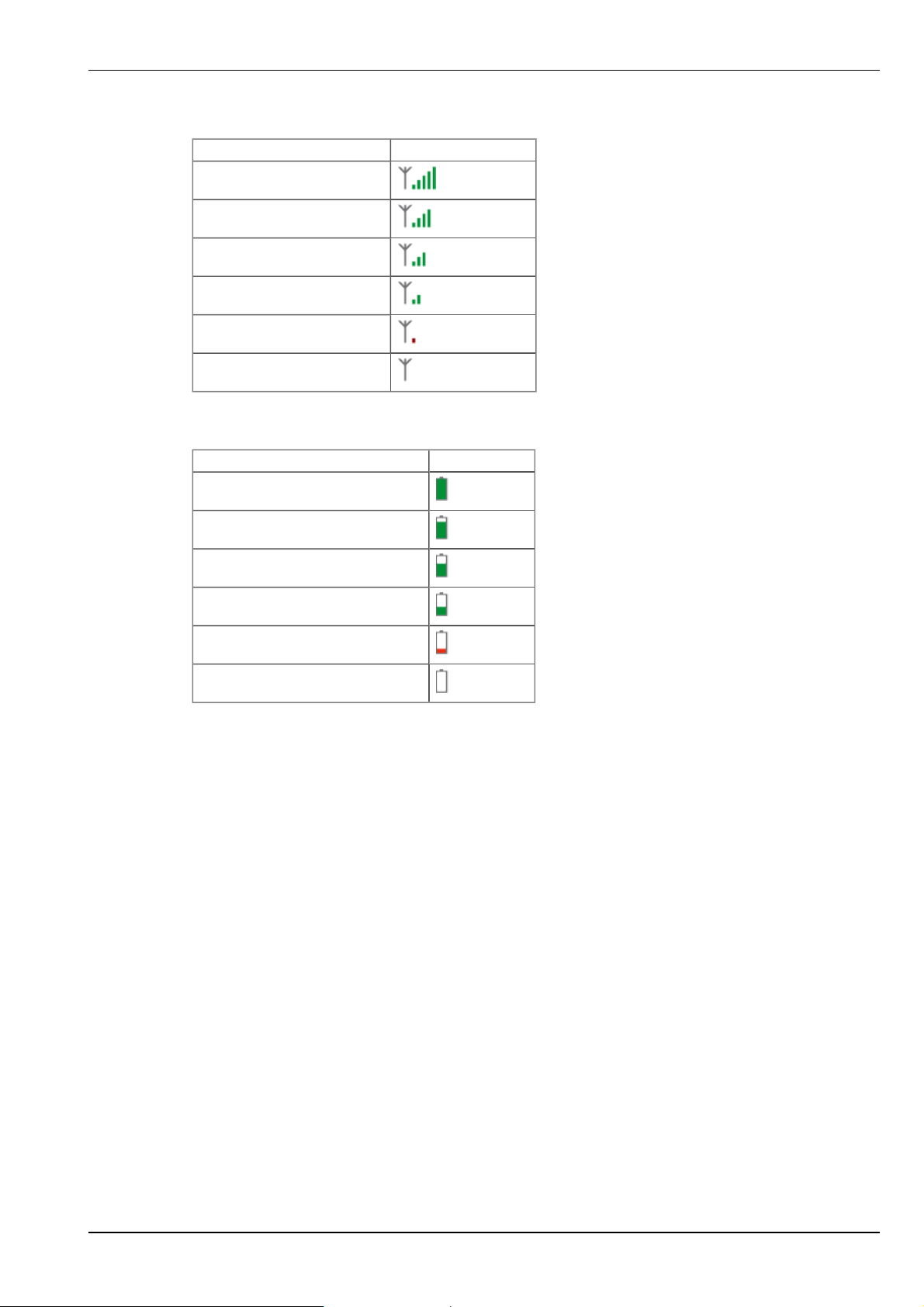
Note: Additional explanation about evaluating the "GSM level":
"GSM level"
>-64dBm
-64 to -73dBm
-74 to -83dBm
-84 to -93dBm
-94 to -107dBm
<= -108dBm
Note: Additional explanation about evaluating the "battery":
"Battery"
> 3,73V
Chapter 9 Initial Start-Up
3,73V...3,65V
3,64V...3,59V
3,58V...3,56V
3,55V...3,21V
<= 3,2V or invalid value
Rev. 03 37


Chapter 10 User interfaces
Chapter 10 User interfaces
The configuration of the myDatasensH2S 1000 is carried out via the web interface on the
myDataweb server (see "User interface on the myDataweb-Server" on page 41), which your
responsible sales partner will provide to you.
10.1 User interface on the myDatasensH2S 1000
10.1.1 Operating elements
Operating elements
1 Solenoid switch 3 Status LED
10.1.1.1 Solenoid switch
The MDN Magnet (206.803) included in the scope of delivery is required for operating the solenoid
switch. The solenoid switch can be used to initiate the ALOHA transmission mode or to instruct the
myDatasensH2S 1000 to immediately transmit the error/status code.
Operation by the
user
Press briefly
(approx. one
second)
Press and hold for
five seconds
Device response
Status LED illuminates Error/status code is displayed (see
Status LED flashes three times and
then remains on
Operation after releasing the solenoid
switch
"Status LED" on page 40)
ALOHA transmission mode
Rev. 03 39

10.1.1.2 Status LED
The status LED is used both to display the error/status codes and to indicate the current operating
status. If the ALOHA transmission mode was activated or the accu or battery pack was connected
(PowerOn), the myDatasensH2S 1000 switches to advanced signalling mode and indicates the
current operating status for 10 minutes via the status LED. During this ten-minute interval, the
error/status codes are transmitted every three seconds. The current operating status is not indicated
during standard signalling mode and the error/status codes are only transmitted every thirty
seconds.
Error/status codes
Flashing
code
0x Transport lock (transmission OFF,
measurement OFF)
Description Solution/cause
If the ALOHA transmission mode is
initiated by means of the solenoid switch,
the myDatasensH2S 1000 resumes
operation in accordance with the
configuration (transmission ON,
measurement ON).
1x Last connection OK
2x Last transmission faulty Try again later
4x Standby (GPRS ON, measurement OFF) see "transport lock"
6x Offline (GPRS OFF, measurement ON) see "transport lock"
7x Network block/no matching provider l Improve position of the antenna
l Check whether the device is located
in the coverage area of one of the
service providers supported by the
integrated SIM chip
(www.microtronics.at/footprint)
l Lift the network block (see
"myDatanetDeviceConfig user
manual" 005.004)
8x No GSM network l Try again later
l Improve position of the antenna
10x No GPRS connection Improve position of the antenna
11x No myDatanet server accessible l Check whether port 51241 is enabled
on the myDataweb server
l Try again later
12x Faulty SIM card Contact support
40 Rev. 03

Chapter 10 User interfaces
Operating statuses
Status LED Description
Flickering Establishing connection
Lights up GPRS connection established or button/solenoid switch actuated
Off Normal measuring operation according to configuration until the next transmission
10.2 User interface on the myDataweb-Server
10.2.1 Site configuration
Note: Several of the configuration fields in the following sub chapters may possibly be hidden depending on the
respective user level. In this case, please contact the myDataweb-Server administrator.
Click on the name of the site in the list of sites to get to the input screen for configuring the site (see
"myDataweb-Server user manual" 005.002).
10.2.1.1 Site
Customer
Specifies to which customer the site is assigned.
icon
Assign site to another customer
Name
Site designation (not relevant for the device or data assignment)
Instrument S/N
Serial number of the device that is linked to the site (device assignment!)
10.2.1.2 Comments
Comments
Empty comment field (is also displayed below the device type in the site list)
10.2.1.3 Measurement channels
10.2.1.3.1 Basis
Gas
Gas Freely selectable channel title for the measurement value of the H2S
concentration
Min Defines the lower scale end of the pointer instruments
Max Defines the upper scale end of the pointer instruments
Unit String, which is used as the measurement value unit by all of the server
display elements
Rev. 03 41

Note: The H2S sensor used indicates a certain cross sensitivity to other gases (see "Cross
sensitivity of the H2S sensor" on page 42).
10.2.1.3.2 Alarms
Warning Value low A warning is initiated if the measurement value drops to or below this
value.
Value high A warning is initiated if the measurement value meets or exceeds this
value.
Alarm Value low An alarm is initiated if the measurement value drops to or below this
value.
Value high An alarm is initiated if the measurement value meets or exceeds this
value.
Hyst % Hysteresis for the all-clear (e.g. hyst = 5%, alarm or warning at 100 -> all-clear at 95)
10.2.1.3.3 Cross sensitivity of the H2S sensor
Gas Concentration Measurement value on the H2S sensor
Carbon monoxide 300ppm 6ppm
Hydrogen 10,000ppm <15ppm
Sulphur dioxide 5ppm <1ppm
Hydrogen cyanide 10ppm -1.4ppm to -0.5ppm
Nitric oxide 35ppm 0ppm
Hydrochloric acid 5ppm 0ppm
Nitrogen dioxide 5ppm -1ppm
Chlorine 1ppm -0.05ppm to +0.04ppm
Ethylene 100ppm 0ppm
10.2.1.4 Calculated channels
Note: The values of the calculated channels are calculated directly for the data output (display on myDataweb
server or download frommyDataweb server). They are not saved in the server database.
10.2.1.4.1 Basis
Title 1-5
Freely selectable channel title for the calculated channels
42 Rev. 03

Mode
Possible calculation modes for the calculated channels
Off --- Calculated channel deactivated
Table Min Defines the lower scale end of the pointer instruments
Max Defines the upper scale end of the pointer instruments
Unit String, which is used as the measurement value unit by all of the
server display elements
Chapter 10 User interfaces
Decimal
places
Digital Invert Inverts the input signal
+, -, x, / Min Defines the lower scale end of the pointer instruments
Max Defines the upper scale end of the pointer instruments
Unit String, which is used as the measurement value unit by all of the
Decimal
places
Shifts element down
Shifts element up
10.2.1.4.2 Calculation
Number of decimal places which are used by all of the server display
elements
server display elements
Number of decimal places which are used by all of the server display
elements
Off --- Calculated channel deactivated
Table
Digital
+, -, x, /
Source Selection of the channel from which the input data is used
Opens the screen for entering the values table (between the table rows is
interpolated linearly, values outside of the defined table are extrapolated
linearly.)
Source Selection of the channel from which the input data is used
High level Signal recognition level
Source Selection of the channel from which the input data is used
+, -, x, /
Source Selection of the channel from which the input data is used
Rev. 03 43

10.2.1.4.3 Alarm
Note: The alarm levels for calculated channels can only be evaluated once the device has transmitted the
measurement data to the myDataweb server.
Alarm low An alarm is initiated if the measurement value drops to or below this value.
Alarm high An alarm is initiated if the measurement value meets or exceeds this value.
Hyst % Hysteresis for the all-clear (e.g. hyst = 5%, alarm or warning at 100 -> all-clear at 95)
10.2.1.5 Internal channels
10.2.1.5.1 Basis
Battery title Freely selectable channel title for the internal battery or accu voltage
Unit String, which is used as the measurement value unit by all of the server
display elements
GSM level title Freely selectable channel title for the GSM level
Unit String, which is used as the measurement value unit by all of the server
display elements
Int.
temperature
title
Freely selectable channel title for the internal device temperature
Unit Selection of the temperature unit that is used by all of the server
display elements
10.2.1.5.2 Alarms
Warning Value low A warning is initiated if the measurement value drops to or below this
value.
Value high A warning is initiated if the measurement value meets or exceeds this
value.
Alarm Value low An alarm is initiated if the measurement value drops to or below this
value.
Value high An alarm is initiated if the measurement value meets or exceeds this
value.
Hyst % Hysteresis for the all-clear (e.g. hyst = 5%, alarm or warning at 100 -> all-clear at 95)
44 Rev. 03

Chapter 10 User interfaces
10.2.1.6 Alarm settings
Acknowledgement Standard The global server setting is used (see "myDataweb-
Server user manual" 005.002) to determine whether
to acknowledge the alarms automatically or manually.
Automatic Alarms are acknowledged automatically as soon as all
of the messages have been sent. If SMS that have a
tariff with a delivery confirmation function have also
been sent, acknowledgement is provided after
delivery confirmation.
Manual Alarms must be acknowledged manually:
Offline alarm Alarm in the event that the device does not respond for longer than the set
transmission cycles
Transfer volumes Standard The configuration for the transfer volume alarm is
adopted from the global server setting (see
"myDataweb-Server user manual" 005.002).
Off The transmission volume alarm is deactivated.
Individual The level at which the transmission volume alarm
should be triggered can be entered in the adjacent
field in KB.
On alarm A The alarm is recorded in the alarm list.
Ü An immediate transmission is initiated.
Q Fastrecording (recording cycle = recording cycle /
factor)
On warning A The alarm is recorded in the alarm list.
Ü An immediate transmission is initiated.
Q Fastrecording (recording cycle = recording cycle /
factor)
On fault alarm A The alarm is recorded in the alarm list.
Ü An immediate transmission is initiated.
Q Fastrecording (recording cycle = recording cycle /
factor)
On fault warning A The alarm is recorded in the alarm list.
Ü An immediate transmission is initiated.
Q Fastrecording (recording cycle = recording cycle /
factor)
Test alarm A test message is sent to all recipients ("parallel" alarm call plan type) and/or
the first recipient ("serial" alarm call plan type) as soon as this page has been
saved. The check box is subsequently reset automatically.
Rev. 03 45

10.2.1.7 Basic setting
Transmission cycle Time between transmissions
Recording cycle Time between measurement data recordings
Measure quick divisor Recording cycle = recording cycle / factor (once triggered by the
alarm/warning)
Time zone Regional settings (not relevant for raw measurement data as this is stored
in the UTC)
Daylight saving time Configuration for automatic time adjustment
Standard The configuration for the time adjustment is adopted
by the global server setting (see "myDataweb-Server
user manual" 005.002).
Off Automatic time adjustment deactivated
USA Predefined setting for the American area
EU Predefined setting for the European area
Position cycle Time between position update
Default view Report, which is loaded by clicking on the device link in the map.
10.2.1.8 FTP export settings
Note: This configuration section is only visible if the "FTP Agent Extended" licence for the myDataweb-Server has
been enabled.
FTP export
profile
Settings of the
selected profile
off FTP export deactivated
"Name of an
FTP export
profile"
List with the FTP export profiles that were created on the
myDataweb-Server (for creating an FTP export profile, see
"myDataweb-Server user manual" 005.002).
shows an overview of the most important parameters of the selected FTP export
profile
FTP directory makes overwriting the standard directory of the selected FTP export profile
possible
10.2.2 Device configuration
Note: Several of the configuration fields in the following sub chapters may possibly be hidden depending on the
respective user level. In this case, please contact the myDataweb-Server administrator.
You can reach the input screen for configuring the device by clicking on the serial number in the site
list (see "myDataweb-Server user manual" 005.002) or by clicking on the device name in the device
name list (see "myDataweb-Server user manual" 005.002).
46 Rev. 03

Chapter 10 User interfaces
10.2.2.1 Comments
Comments
Empty comment field (is also displayed below the site name in the measurement instrument
list)
10.2.2.2 Measurement instrument
Customer Name of the customer to whom the measurement instrument is assigned
IMSI IMSI of the used SIM chip or SIM card
Serial number Serial number of the instrument
Instrument
class
Telephone
number
Instrument
flags
Firmware
version
Modem
version
OS version OS version of the modem
Last
connection
Last wakeup
Last
disconnection
Last
transmission
error
The instrument class of the site and instrument must match for an instrument to be
able to be connected to a site.
Telephone number of the SIM card. The control SMS messages (e.g. wakeup) are
sent to this number. Format: +43555837465
Additional information on the instrument class (for internal use)
Current software version installed on the measurement controller
Current software version installed on the modem controller
In each case, the last time stamp of the affected operation
Last Aloha
connection
Rev. 03 47

Firmware
update
Firmware type Released Only firmware versions that have successfully undergone
Off Firmware update is deactivated
On As soon as a new version of the selected firmware type is
available, this is installed immediately.
Even if tag is missing Firmware is also transmitted to the device if the device has
not transmitted the current firmware version to the server.
(NOT RECOMMENDED!)
Allow downgrade Facilitates the installation of an older firmware version than
the one on the device. (NOT RECOMMENDED!)
Once Performs a single firmware update. If no new firmware is
available or the firmware was installed successfully, the
firmware update is automatically switched to "OFF".
internal and field testing are installed (this practically
eliminates malfunctions).
Release candidate Only firmware versions that have successfully undergone
internal testing are installed (malfunctions cannot be
excluded).
Beta release Even firmware versions that have not successfully
undergone all of the internal tests are installed
(malfunctions may occur).
10.2.2.3 Device-specific settings
Measurement
Activates/deactivates the measurement
Transmission
Activates/deactivates the transmission
Last calibration
Time of the last calibration
Last trimming
Time of the last trimming
Scale
The trim factor (kTrim) is used to adjust the slope determined during the calibration, which is
then used to convert the raw value to a measurement value in ppm (see "Calculation of the
trimmed H2S measurement value" on page 23).
Offset
Trim offset (d
) in ppm (see "Calculation of the trimmed H2S measurement value" on page
Trim
23)
10.2.2.4 GPRS
SIM tariff
Selected SIM tariff
48 Rev. 03

Chapter 11 Maintenance
Chapter 11 Maintenance
Important note: The work described in this section of these instructions may only be performed by qualified personnel to prevent damage to the instrument.
Before maintenance, cleaning and/or repair work, the device must absolutely be deenergised
(zero potential).
11.1 General maintenance
l Regularly check the myDatasensH2S 1000 for mechanical damage.
l Clean the myDatasensH2S 1000 with a soft, moist cloth. Use a mild cleaning agent, if nec-
essary. Attention: Due to the electrostatic effects, the protective armour must not be rubbed
with cloths in the Ex zone.
11.2 Accu or battery pack
While battery packs are intended for single use and must be disposed of accordingly after depletion,
accu packs can be recharged and used again and again. However, the service time of accu packs is
not indefinite. In addition to regular servicing and maintenance, its service life is also dependent on
the frequency of use and the operating and storage conditions.
11.3 Replacing the accu or battery pack
Note: The accu pack does not need to be replaced in devices for which a maintenance agreement has been concluded, as recharging the accu pack is included in the scope of the maintenance contract. Under normal operating conditions, the capacity of the accu pack will cover
the 6 -month period to the next service. Additionally, a condition of the maintenance contract is that the accu pack is not disconnected from the device. A seal, that is covered by the
protective armour, is attached to the device for this purpose. Please note that if this seal if
broken, this will render the maintenance contract invalid.
Warranty seal
1. Ensure that all of the relevant data was transmitted to the myDataweb server. If necessary initiate the ALOHA transmission mode using the solenoid contact (see "ALOHA transmission
mode" on page 21) and then check again that all of the relevant data has been transmitted.
2. Now remove the antenna.
Rev. 03 49

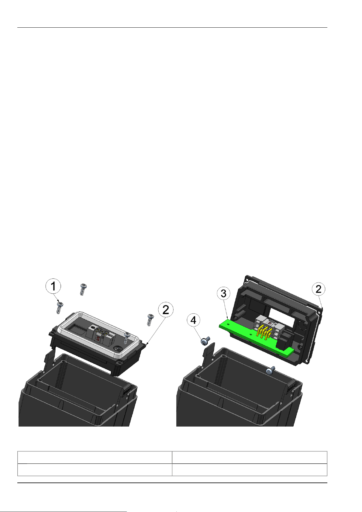
3. First of all, press the upper end of the device out of the protective armour (see "Removing the
protective armour - step1" on page 50) and then remove it fully (see "Removing the protective armour - step2" on page 50)
Removing the protective armour - step1 Removing the protective armour - step2
4. Briefly (approx. 1 sec.) activate the solenoid switch (see "Operating elements" on page 39) to
prepare the myDatasensH2S 1000 for the removal of the accu pack. This ensures that the most
recently generated data is saved permanently. If the device is not notified that the accu pack is
being removed by briefly pressing the solenoid switch, the measurement data from the last
half an hour can be lost.
5. Push and hold both of release buttons (see "Removing the accu or battery pack" on page 50)
while pulling the accu or battery pack out of the myDatasensH2S 1000 .
Removing the accu or battery pack
1 Left release button 2 Right release button
The following step is only necessary if an accu pack is being used
50 Rev. 03

Chapter 11 Maintenance
6. Charge the accu pack. A description is provided in the chapter "Charging the accu pack" on
page 52
7. Due to the low energy consumption, one accu charge will provide several months of operating
time. During this time, the myDatasensH2S 1000 is located in an environment that strongly corrodes the seal between the device and the accu or battery pack. The accu cover must therefore
be replaced every time the device is recharged. Instructions are provided in the chapter
"Replacing the accu cover" on page 54.
Important note: When using accu packs with an EX certificate that is indicated by the
marking on the type plate, the accu cover must only be replaced by individuals who are
certified and specially trained by the manufacturer.
8. Most damage to the myDatasensH2S 1000 can be attributed to damaged or contaminated
seals. The seals on the accu or battery pack and the contact surface of the device must therefore be cleaned before the seal is greased again. A detailed description is provided in the chapter "Maintenance of the accu seal" on page 55.
9. Now reconnect the accu or battery pack and the myDatasensH2S 1000 .
10. Clean the protective armour before assembly. It is also recommended to lightly spray the corners and surfaces in accordance with Figure "Oiling the protective armour" on page 51 using
the paraffin oil spray included in the myDatanet Service Kit (206.324 ). This facilitates
assembly and the subsequent removal of the protective armour during the next service.
l The protective armour must only be cleaned with mild cleaning agents.
l The protective armour must not be rubbed with cloths in the Ex zone.
Oiling the protective armour
11. Assemble the protective armour according to step 1 to 3 in Figure "Assembly of the protective
armour" on page 52. Ensure that you insert the device in to the protective armour in such a
way that the type plate can be read following assembly. Otherwise, the solenoid switch, status
LED and antenna connection cannot be accessed via the cut-out in the upper section of the
protective armour (see "Operating elements" on page 39).
Important note: Do not use any sharp objects for the assembly.
Rev. 03 51

Assembly of the protective armour
Step1 Step2 Step3
11.3.1 Charging the accu pack
The accu packs are delivered in a charged state.
Instructions on replacing the accu pack are provided in "Replacing the accu or battery pack" on
page 49.
Important note:
l
The accu pack can be replaced in the Ex area but must not be charged. Please note that
if the seal is broken, the maintenance contract for these devices shall be void (see
"Warranty seal" on page 49).
l
When recharging the accu pack it must be located outside the Ex area in a dry environment.
l
Only the Charger AC15 (206.701) must be used to charge lithium-ion accu packs. The
charger specifications must be observed. The use of atypical chargers can destroy the
accu pack (e.g. causing the cells to leak or an explosion, etc).
52 Rev. 03

Chapter 11 Maintenance
Charger and accu pack
1 Charger AC15 (206.701) 3 Charging plug
2 Status LED of the Charger AC15
4 Accu pack, e.g. AP424DA (206.705)
Flashing orange: Impulse charge (accu pack
fully discharged)
Orange: Accu pack is being charged
Green: Charging completed
Red: Accu pack damaged
The charging process starts as soon as the accu pack is connected to the charger. The accu pack is
fully discharged if the status LED on the charger flashes orange. The charging process will take considerably longer in this case. A normal charging process is started, if the status LED is orange. The
charging process is complete when the status LED turns green. Normally, the charging process does
not take longer than 10 hours.
If the status LED turns red, the accu pack is faulty. Possible reasons for this include a broken cable,
short circuit or defective cells. In this case, the used accu pack must be replaced with a new one.
Note: A new accu pack will only achieve full capacity after three complete charging and discharge cycles. Accu
packs are wear parts that lose capacity over time. The capacity is also reduced at high or low ambient temperatures and under intensive use.
Rev. 03 53
Important note: The use of spare and wear parts (e.g. accu or battery packs, etc.) that are not
approved by the manufacturer will render the warranty invalid. The protective case must be
installed in operation.
Note: Ensure that accu and battery packs are disposed of in line with environmental requirements. Used accu or battery packs can be returned to the manufacturer or handed in at suitable collection points.
11.3.2 Replacing the accu cover
The optional "myDatanet Service Kit (206.324 )" equipment is required for replacing the accu
cover.
Important note:
l
The accu cover must not be replaced in the Ex area.
l
The accu cover must be replaced if impurities on the seal of the accu cover cannot be
removed without damaging the seal.
l
The accu cover must definitely be replaced in the event of noticeable deformations of
the seal or the accu cover.
l
The manufacturer must be contacted if there is any indication of moisture within the
sealing area (see ../common/Kontaktinformationen.htm).
l
The accu cover must generally be replaced on devices supplied before April 2009.
l
The maximum permissible torque for all of the screws is 0.4Nm and must not be
exceeded under any circumstances!
Replacing the accu cover - step1 Replacing the accu cover - step2
1 Screw 3 Accu electronics
2 Accu cover 4 Screw including shoulder washer
54 Rev. 03

Chapter 11 Maintenance
1. Unscrew all four of the screws (1) that secure the accu cover (see "Replacing the accu cover step1" on page 54). A suitable Torx wrench (Tx10) is included in the myDatanet Service Kit
(206.324 ).
2. Carefully lift the accu cover.
Important note: Be particularly careful to ensure that the wires that are underneath and
connect the accu electronics to the accu cells are not damaged.
3. Loosen both of the screws (4) that secure the accu electronics and carefully remove the accu
electronics from the accu cover (see "Replacing the accu cover - step2" on page 54).
4. Then push the accu electronics into the new accu cover and secure the accu electronics with
the screws provided (4).
Important note: Ensure that you do not mix up the screws (4) for securing the accu electronics with the screws (1) for securing the accu cover.
5. Place the accu cover back on the accu pack and secure it with all four of the screws (1).
Tighten all four of the screws crosswise so that the accu cover is affixed uniformly (ensure the
maximum permissible torque of 0.4Nm is maintained).
11.3.3 Maintenance of the accu seal
The optional "myDatanet Service Kit (206.324 )" equipment is required for maintaining the accu
seal.
Important note:
l
Ensure that any impurities are eliminated.
l
The seal of the device is not guaranteed if the sensor head and accu cover are not
cleaned thoroughly.
l
If residual dirt cannot be removed from the accu cover, it must be replaced (see
"Replacing the accu cover" on page 54).
l
The seal must be protected before EACH assembly with a bead of grease from the
syringe included in the myDatanet Service Kit (206.324 ).
1. After removing the accu or battery pack, clean the contact surface on the myDatasensH2S
1000 with a standard cleaning cloth and cotton buds.
Rev. 03 55
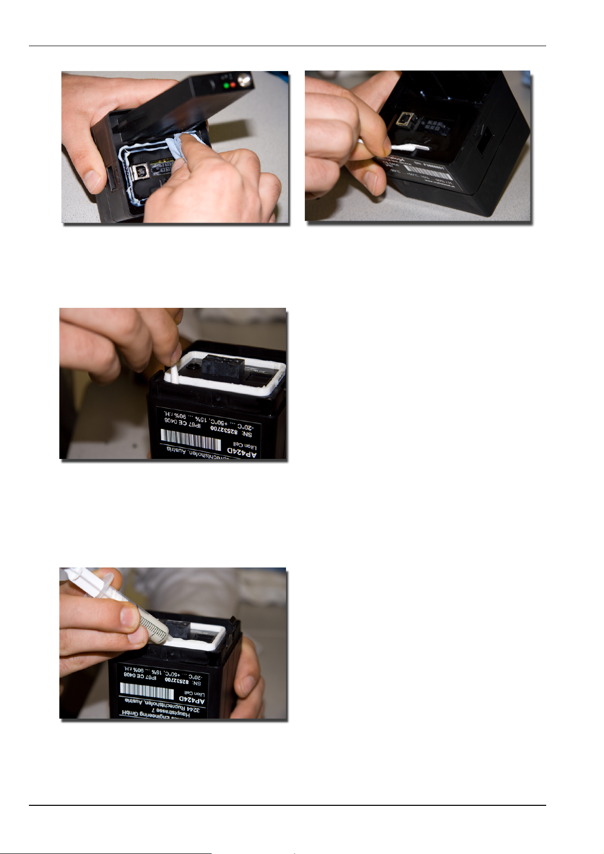
Cleaning the myDatasensH2S 1000 - step1 Cleaning the myDatasensH2S 1000 - step2
2. Clean the seal and area around the seal of the accu or battery pack with a cleaning cloth and
cotton buds.
Cleaning the accu or battery pack
3. To ensure impermeability, it is particularly important to apply a bead of grease on the seal
(approx. 0.5ml) using the syringe included in the myDatanet Service Kit (206.324 ).
Important note: The seal must be greased before EVERY assembly of the accu or battery pack.
Applying the bead of grease
56 Rev. 03

Chapter 11 Maintenance
11.4 Maintenance of the antenna socket
The optional "myDatanet Service Kit (206.324 )" equipment is required for maintaining the
antenna socket.
Important note:
l
The three small O-rings on the contact pin of the antenna socket must be installed to
improve the seal.
l
The O-rings must be checked at regular intervals and must be replaced with new ones
from the myDatanet Service Kit (206.324 ) in the event of brittleness or damage.
Installation of the three small O-rings
1 0.75x1.2 mm O-ring (included in the scope of
delivery of the 206.324 )
1. Place the three small O-rings on the contact pin of the antenna socket. The O-rings are placed
in the end position during initial assembly of the antenna.
11.5 Maintenance of the antenna connector
The optional "myDatanet Service Kit (206.324 )" equipment is required for maintaining the
antenna connector.
Important note:
l
The O-ring must generally be used for all radio receiver antenna connectors to improve
the seal and must be replaced as necessary.
l
The O-ring must be checked at regular intervals and must be replaced with a new one
from the myDatanet Service Kit (206.324 ) in the event of brittleness or damage.
Rev. 03 57

Antenna including assembled O-ring
1 Antenna 900 FME (206.801) 2 6.1x1.6 mm O-ring (included in the scope of
delivery of the 206.324 )
1. Assemble the O-ring on the antenna connector according to the Figure "Antenna including
assembled O-ring" on page 58.
2. The O-ring must be pressed firmly on to the antenna socket following assembly of the
antenna. Check the number of O-rings on the contact pin of the antenna socket.
Important note: Do not apply too much force when tightening the antenna. Tighten the
antenna or antenna extension with your hand. Do not use a tool except for the plastic
open-ended spanner that is included in the myDatanet Service Kit (206.324 ) that will
break if the applied force is too strong.
11.6 Calibration, trimming and zero-point alignment
CAUTION:
To prevent any damage to the device, the work described in this section of these instructions
must only be performed by qualified personnel trained to handle H2S calibration gas.
Note: Devices for which a maintenance agreement was concluded do not need to be
trimmed or calibrated by the customer, as both of these processes are included in the scope
of the maintenance contract. The calibration is completed every 6 months as part of the
ongoing service. As the maintenance contract stipulates that the accu pack is not disconnected from the device, the USB interface that is required for trimming or calibration purposes cannot be accessed. To ensure that these conditions are maintained, a seal is attached
to the device (see "Warranty seal" on page 49), which is however covered by the protective
armour. Please note that if this seal if broken, this will void the maintenance contract.
58 Rev. 03

Note: Additional explanations on the difference between calibration, trimming and zero-point alignment
Action Amount of time Required tools Accuracy
Calibration
(see "Calibration" on page 59)
Trimming
(see "Trimming" on page 64)
Zero-point alignment
(see "Zero-point alignment" on page 68)
11.6.1 Safety instructions for handling H2S gas
DANGER:
Extreme caution is required when handling calibration gases!
Hydrogen sulphide is a neurotoxic substance that can cause poisoning and even death
depending on the concentration.
Chapter 11 Maintenance
It has the following effects on humans:
l ~ 0.1ppm: Odour threshold
l from 20ppm: Corneal damage following prolonged exposure
l approx. 100ppm: Irritation of the mucous membranes in the eyes and respiratory system, sal-
ivation, irritation of the throat
l > 200ppm: Headache, breathing difficulties
l > 250ppm: Impairment of the olfactory receptors
l > 300ppm: Nausea
l approx. 500ppm: Weakness, drowsiness, dizziness (life threatening within a few minutes)
l > 500 ppm: Seizures, unconsciousness (fatal within a few seconds)
Long-term effects following exposure to low doses include tiredness, loss of appetite, headaches,
irritability, poor memory and a lack of concentration.
The greatest caution must therefore be exercised depending on the calibration gas used.
The maximum admissible concentration (MAC value) at the workplace for H2S is 10ppm.
11.6.2 Calibration
Note: The calibration of a myDatasensH2S 1000 must only be completed in a specially
equipped calibration space.
Rev. 03 59

11.6.2.1 Calibration specifications
Important note:
l
No one is allowed to enter the calibration room without training.
l
Employees must only use those gases or gas concentrations that they are trained to
use according to the relevant risk potential.
l
Alcohol-based cleaning agents must not be used.
l
Before entering the calibration room, the employee must have been in an environment
free of alcoholic vapours for at least 30 minutes.
l
The ESD safety guidelines must be observed in the calibration room.
11.6.2.2 Calibration room equipment
The following basic equipment must be available in the calibration room:
l Ensure sufficient ventilation is provided.
l Gas cylinders must be assembled and stored properly.
l The fittings on the gas discharge station must correspond to the working pressure.
l A computer is required for the myDatanetDeviceConfig configuration program.
l An extraction device that is in permanent operation during the calibration process must be pro-
vided.
More detailed provisions must be taken from the applicable standards on installing a gas storage
centre for the relevant country.
Normally, gas storage centres must be approved and accepted by the legislative authorities.
The gas storage centre must be designed for a hydrogen sulphide concentration of up to 200ppm.
11.6.2.3 Calibration process
Important note: Before calibration the device must be stored in an environment that is free
of H2S and alcoholic vapours for twelve hours.
Note: All of the screenshots show version3.8 of the myDatanetDeviceConfig configuration program. The newer versions may include minor changes to the appearance of the program.
1. Start the myDatanetDeviceConfig configuration program. It is available for download in the
service area of your myDataweb server (see "myDataweb-Server user manual" 005.002). Installation instructions are included in the user manual for the myDatanetDeviceConfig ("myDatanetDeviceConfig user manual" 005.004).
60 Rev. 03

Chapter 11 Maintenance
myDatanetDeviceConfig
2. Remove the protective armour and disconnect the device from the accu pack (see "Replacing
the accu or battery pack" on page 49) to expose the USB interface (see "Overview" on page
16).
3. Connect the myDatasensH2S 1000 to the PC using the cable supplied USB15AB (206.601). If
the device is being connected to the PC for the first time, the driver will need to be installed.
From Windows Vista onwards, this will complete automatically. Instructions on installing the
driver on older versions of Windows are included in the user manual for the myDatanetDeviceConfig ("myDatanetDeviceConfig user manual" 005.004).
4. The calibration must only be completed by a restricted group of people. A password is therefore required. For this purpose, select "Program -> Activate Superuser Features" and enter the
password that you received from the administrator of your myDataweb server in the dialogue
window that appears.
Note: Additional tabs will be displayed within the configuration program depending on the level of the password.
Rev. 03 61

Screenshot following input of the password including additional tabs
5. Select the "Calibration" tab (see "Screenshot following input of the password including additional tabs" on page 62) and wait for the warm-up time to be completed.
6. Ensure that 0ppm is selected for the lower reference point. Wait five minutes before pressing
the button to set the lower reference point. During these five minutes, it must be ensured that
the H2S concentration in the calibration room is 0ppm (extraction active and all of the valves
on the gas cylinders are closed).
"Calibration" tab
1 Lower reference point (target value in ppm) 5 Detected offset
62 Rev. 03
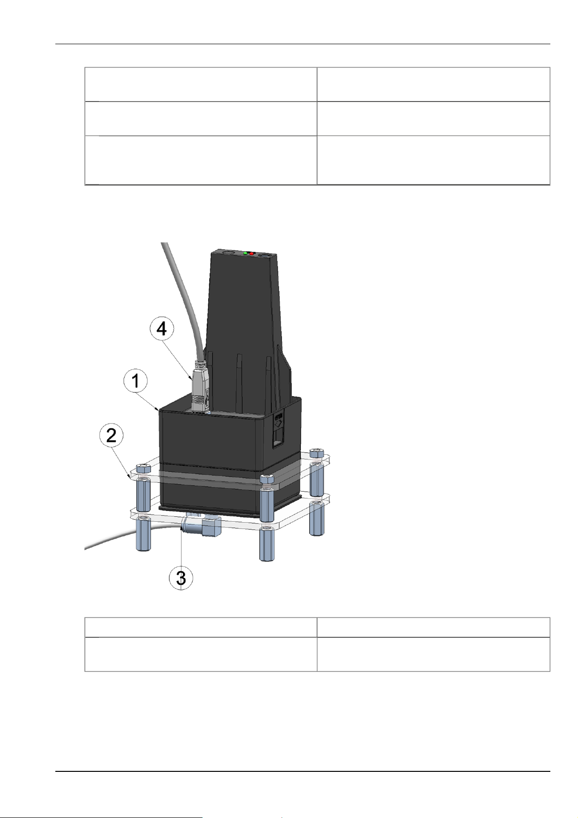
Chapter 11 Maintenance
2 Upper reference point (target value in
6 Detected slope
ppm)
3 Raw value 7 Button for adopting the lower reference
point
4 H2S measurement value (calculated with
the currently valid values for the offset and
8 Button for adopting the upper reference
point
slope)
7. Place the myDatasensH2S 1000 in the myDatasens calibration adapter (206.813), which
should already be connected to the gas extraction station.
Place the myDatasensH2S 1000 in the calibration adapter
1 myDatasensH2S 1000 3 Hose to the gas extraction station
2 myDatasens calibration adapter (206.813) 4 USB15AB (206.601) connection cable to the
PC
8. Ensure that the concentration value of the gas that you are using for the calibration is entered
for the upper reference value (recommendation: 30-150ppm). Set the flow controller for the
Rev. 03 63

calibration gas to 0.5l/min. and gas the device for five minutes. Then press the button to
adopt the upper reference point (see ""Calibration" tab " on page 62).
9. Press the "Save" button to transfer the determined offset and slope values in myDatasensH2S
1000 (see ""Calibration" tab " on page 62).
10. The "Print" button is used to generate the calibration report that must always be created to
ensure traceability. After pressing the "Print" button, a dialogue window will appear in which
additional information can be added. The report is printed once this window is closed by
selecting "OK". The standard printer is always used for this purpose without any additional
prompt. A PDF writer can also be used for this purpose.
11.6.3 Trimming
Important note:
l
Employees must only use those gases or gas concentrations that they are trained to
use according to the relevant risk potential.
l
Alcohol-based cleaning agents must not be used.
The optional "Calibration set H2S 30ppm (206.810)" equipment is recommended for implementing
the trimming process. If you are under the impression that based on the operational demands, the
calibration of the sensor is no longer entirely correct, this can be compensated by the trimming process. This means that the time until the next scheduled calibration can be bypassed. The trim can
then be removed again during the next calibration. The basic calibration of the device is not
changed by the trimming process. The trim can be removed again at any time by clicking on the
"Reset" button (see ""Trim" tab " on page 66).
Note: All of the screenshots show version3.8 of the myDatanetDeviceConfig configuration program. The newer versions may include minor changes to the appearance of the program.
1. Start the myDatanetDeviceConfig configuration program. It is available for download in the
service area of your myDataweb server (see "myDataweb-Server user manual" 005.002). Installation instructions are included in the user manual for the myDatanetDeviceConfig ("myDatanetDeviceConfig user manual" 005.004).
64 Rev. 03

Chapter 11 Maintenance
myDatanetDeviceConfig
2. Remove the protective armour and disconnect the device from the accu pack (see "Replacing
the accu or battery pack" on page 49) to expose the USB interface (see "Overview" on page
16).
3. Connect the myDatasensH2S 1000 to the PC using the cable supplied USB15AB (206.601). If
the device is being connected to the PC for the first time, the driver will need to be installed.
From Windows Vista onwards, this will complete automatically. Instructions on installing the
driver on older versions of Windows are included in the user manual for the myDatanetDeviceConfig ("myDatanetDeviceConfig user manual" 005.004).
4. The trimming process can only be completed by a restricted group of people. A password is
therefore required. For this purpose, select "Program -> Activate Superuser Features" and enter
the password provided by the administrator of your myDataweb server in the dialogue window
that appears.
Note: Additional tabs will be displayed within the configuration program depending on the level of the password.
Rev. 03 65

Screenshot following input of the password including additional tabs
5. Select the "Trim" tab (see "Screenshot following input of the password including additional
tabs" on page 66) and wait for the warm-up time to be completed.
6. Ensure that 0ppm is selected for the lower reference point. Wait five minutes before pressing
the button to set the lower reference point. During these five minutes, it must be ensured that
no H2S gas reaches the sensor.
"Trim" tab
66 Rev. 03

Chapter 11 Maintenance
1 H2S measurement value (calculated with
6 Detected offset
the currently valid values for the offset and
slope)
2 Upper reference point (target value in
7 Detected slope
ppm)
3 Lower reference point (target value in ppm) 8 Input field for the manual entry of the off-
set
4 Button for adopting the lower reference
point
9 Input field for the manual entry of the
slope
5 Button for adopting the upper reference
point
7. Place the myDatasensH2S 1000 in the myDatasens calibration adapter (206.813), which
should already be connected to the source of the calibration gas.
Place the myDatasensH2S 1000 in the calibration adapter
1 myDatasensH2S 1000 3 Hose to the source of the calibration gas
2 myDatasens calibration adapter (206.813) 4 USB15AB (206.601) connection cable to the
PC
Rev. 03 67

8. Ensure that the concentration value of the gas that you are using for trimming is entered for
the upper reference value (30ppm when using the "Calibration set H2S 30ppm (206.810)" ).
Set the flow controller for the calibration gas to 0.5l/min. and gas the device for five minutes.
Then press the button to adopt the upper reference point (see ""Trim" tab " on page 66). During this process the values determined for the offset and slope are also transferred to myDatasensH2S 1000 .
Note: There is also an option to display the input fields for manually adding the offset and slope by selecting the checkbox "More Settings" (see ""Trim" tab " on page 66). By clicking on the "Save" button, the
manually entered values for the offset and slope are transferred to myDatasensH2S 1000 .
11.6.4 Zero-point alignment
The zero-point alignment is used to equalise adjustments of the zero-point. The basic calibration of
the device is not changed by the zero-point alignment.
Note: All of the screenshots show version3.8 of the myDatanetDeviceConfig configuration program. The newer version may include minor changes to the appearance of the program.
1. Start the myDatanetDeviceConfig configuration program. It is available for download in the
service area of your myDataweb server (see "myDataweb-Server user manual" 005.002). Installation instructions are included in the user manual for the myDatanetDeviceConfig ("myDatanetDeviceConfig user manual" 005.004).
68 Rev. 03
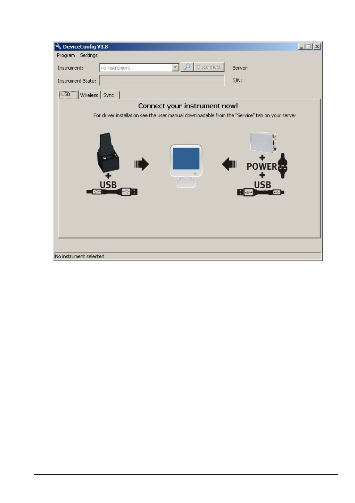
Chapter 11 Maintenance
myDatanetDeviceConfig
2. Remove the protective armour and disconnect the device from the accu pack (see "Replacing
the accu or battery pack" on page 49) to expose the USB interface (see "Overview" on page
16).
3. Connect the myDatasensH2S 1000 to the PC using the cable supplied USB15AB (206.601). If
the device is being connected to the PC for the first time, the driver will need to be installed.
From Windows Vista onwards, this will complete automatically. Instructions on installing the
driver on older versions of Windows are included in the user manual for the myDatanetDeviceConfig ("myDatanetDeviceConfig user manual" 005.004).
4. Select the "Zero" tab (see ""Zero" tab " on page 70) and wait for the warm-up time to be completed.
5. Ensure that no H2S gas reaches the sensor. Wait until the displayed ppm value is stable and
then click on "zero".
Rev. 03 69
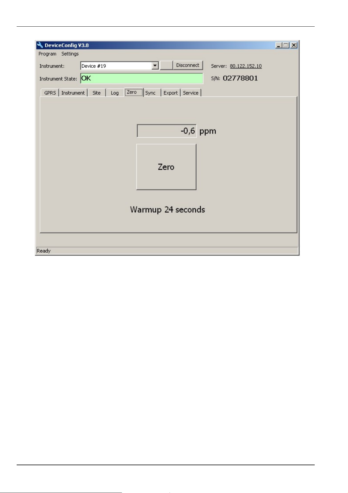
"Zero" tab
70 Rev. 03

Chapter 12 Removal/disposal
Chapter 12 Removal/disposal
Dispose of the device in accordance with the locally valid environmental regulations for electronic
products.
Accu and/or battery packs must not remain connected to the myDatasensH2S 1000 after
discharging. Ensure that accu and battery packs are disposed of in line with environmental
requirements.
Rev. 03 71


Chapter 13 Troubleshooting and repair
Chapter 13 Troubleshooting and repair
13.1 General problems
Problem Cause/solution
Device does not
respond (status LED
always off)
l An accu or battery pack that is not approved for use in the Ex area is
being used. Solution: Only use accu and battery packs listed in chapter
"Accu and battery packs" on page 81.
l Fully discharge accu and battery packs
Communication
problems
Not all or no data is
available on the
server
H2S measurement
value is not
plausible
Alarm state of a
measurement value
was not identified
Alarm status was
not transmitted
although the data is
present
l Evaluate the status LED blink code (see "Status LED" on page 40).
l Load the device log from the myDatasensH2S 1000 or the myDataweb
server and use myDatanetDeviceConfig for the evaluation (see
"Evaluating the device log" on page 79).
l The accu or battery pack capacity is virtually depleted.
l The connection was interrupted during transmission, which is indicated
by a time-out entry in the connection list (see "myDataweb-Server user
manual" 005.002). Solution: Initiate a ALOHA transmission or wait for
the cyclical transfer.
l The assignment of the device and site is not correct (see "Site" on page
41).
Check the date of the last calibration (see "Device-specific settings" on page
48). The myDatasensH2S 1000 must be calibrated every 6 months.
Increase the recording cycles (attention: This will increase the required data
volume).
l Check the alarm settings of the measurement channel
l The connection was interrupted during transmission, which is indicated
by a time-out entry in the connection list (see "myDataweb-Server user
manual" 005.002). Solution: Initiate a ALOHA transmission or wait for
the cyclical transfer.
Alarm message was
not sent although
the alarm was
signalled
l Check the settings of the alarm call plan (see "myDataweb-Server user
manual" 005.002).
l Check the address data of the alarm call plan (see "myDataweb-Server
user manual" 005.002).
Rev. 03 73

13.2 Log entries and error codes
Log entry Parameter
Description
Code Plain text Code Plain text
1020 ERROR SOD ## --- Internal system error
There may be a hardware problem if this
error is included in the device log several
times with the same parameter code. Contact
the manufacturer in this case (see "Contact
information" on page 85).
1200 MODEM ERROR Modem error (see "Modem error" on page
76)
1600
(1/2)
STATE
(1/2)
1 OK Last connection OK
2 TRANSMISSION
Last transmission faulty
ERROR
Try again later
3 MEASUREMENT
Last measurement faulty
ERROR
l Check the configuration
l Check the connection between the
device and the sensor
4 HOLD Standby (GPRS ON, measurement OFF)
If the ALOHA transmission mode is initiated,
the myDatasensH2S 1000 switches back into
"RUN" mode (GPRS ON, measurement ON).
5 TRANSPORT Transport lock (GPRS OFF, measurement
OFF)
see "Standby"
6 OFFLINE Offline (GPRS OFF, measurement ON)
see "Standby"
74 Rev. 03

Chapter 13 Troubleshooting and repair
Log entry Parameter
Code Plain text Code Plain text
1600
(1/2)
STATE
(1/2)
7 NO NET (NET LOCK) Netlock/no matching provider
8 NO NET No GSM network
10 GPRS ERROR No GPRS connection
11 IP ERROR No myDataweb server available
Description
l Try to improve the position of the
antenna.
l Check whether the device is in the
coverage area
(www.microtronics.at/footprint).
l Lift the network block (see
"myDatanetDeviceConfig user manual"
005.004)
l Improve the position of the antenna
l Try again later
Try to improve the position of the antenna.
l Check whether port 51241 is enabled
on the myDataweb server.
l Try again later
12 SIM CARD ERROR Faulty SIM chip
Contact support.
Rev. 03 75

13.2.1 Modem error
Log entry Parameter
Code Plain text Code Plain text
GPRS error (1/2)
1200 BEARER LINE BUSY -993 --- Line busy
Try again later
BEARER NO
-992 --- No answer
ANSWER
l Try again later
l Check whether the device is in the
coverage area
(www.microtronics.at/footprint).
BEARER NO
-991 --- No carrier
CARRIER
l Try again later
l Check whether the device is in the
coverage area
(www.microtronics.at/footprint).
BEARER GPRS
-988 --- GPRS setup failure
FAILED
l Try to improve the position of the
antenna
l Check whether the device is in the
coverage area
(www.microtronics.at/footprint).
Description
BEARER PPP LCP
FAILED
BEARER PPP AUTH
FAILED
BEARER PPP IPCP
FAILED
BEARER PPP LINK
FAILED
BEARER PPP TERM
REQ
-987 --- Error when negotiating the LCP
Internal error
-986 --- Error occurred during PPP authentication
Internal error
-985 --- Error when negotiating the IPCP
Internal error
-984 --- PPP receiver does not react to echo request
Internal error
-983 --- PPP session terminated by the receiver.
Internal error
76 Rev. 03

Chapter 13 Troubleshooting and repair
Log entry Parameter
Code Plain text Code Plain text
GPRS error (2/2)
BEARER CALL
-982 --- Incoming call refused
REFUSED
Try again later
BEARER UNKNOWN -981 --- Try again later
Error when establishing the GPRS connection
1200 BEARER BAD HDL -980 --- Invalid handling
Internal error
BEARER BAD STATE -979 --- The carrier was not stopped.
Internal error
BEARER DEV -978 --- Error occurred during link layer initialisation
Internal error
BEARER GPRS
-977 --- Internal error
START UNKNOWN
Description
Error when disconnecting the GPRS connection
1200 BEARER GPRS STOP
-976 --- Invalid handling
BAD HDL
Internal error
BEARER GPRS STOP
-975 --- Internal error
UNKNOWN
1200 NETLOCK FAILURE -970 --- Error when selecting the network
l Check the settings for the netlock or
remove the netlock1).
l Check whether the device is in the
coverage area
(www.microtronics.at/footprint).
1)
A netlock can only be activated on devices with a USB connector in conjunction with the myDatanetDeviceConfig
configuration program.
Rev. 03 77

Log entry Parameter
Description
Code Plain text Code Plain text
1200 BAND SEL FAILED -969 --- A network could not be found on the
GSM900/1800 or on the GSM85071900
band.
l Try to improve the position of the
antenna.
l Check whether the device is in the
coverage area
(www.microtronics.at/footprint).
TCP channel error (1/2)
1200 CHANNEL ABORTED -965 --- An attempt is being made to write to/read a
TCP client that is no longer available.
Try again later
CHANNEL CSTATE -964 --- The channel is not in the "WIP_CSTATE_
READY" state.
Try again later
CHANNEL NOT
-963 --- The option is not supported by the channel.
SUPPORTED
Try again later
CHANNEL OUT OF
RANGE
-962 --- The optional value is outside the permissible
range.
Try again later
CHANNEL MEMORY -961 --- Internal error
CHANNEL INTERNAL -960 --- Internal error
CHANNEL INVALID -959 --- Invalid option or parameter
Internal error
TCP DNS FAILURE -958 --- The name could not be resolved in an IP
address.
Internal error
CHANNEL
-957 --- There are no further TCP buffers available.
RESOURCES
Try again later
CHANNEL PORT IN
-956 --- TCP server port is already being used.
USE
Try again later
78 Rev. 03
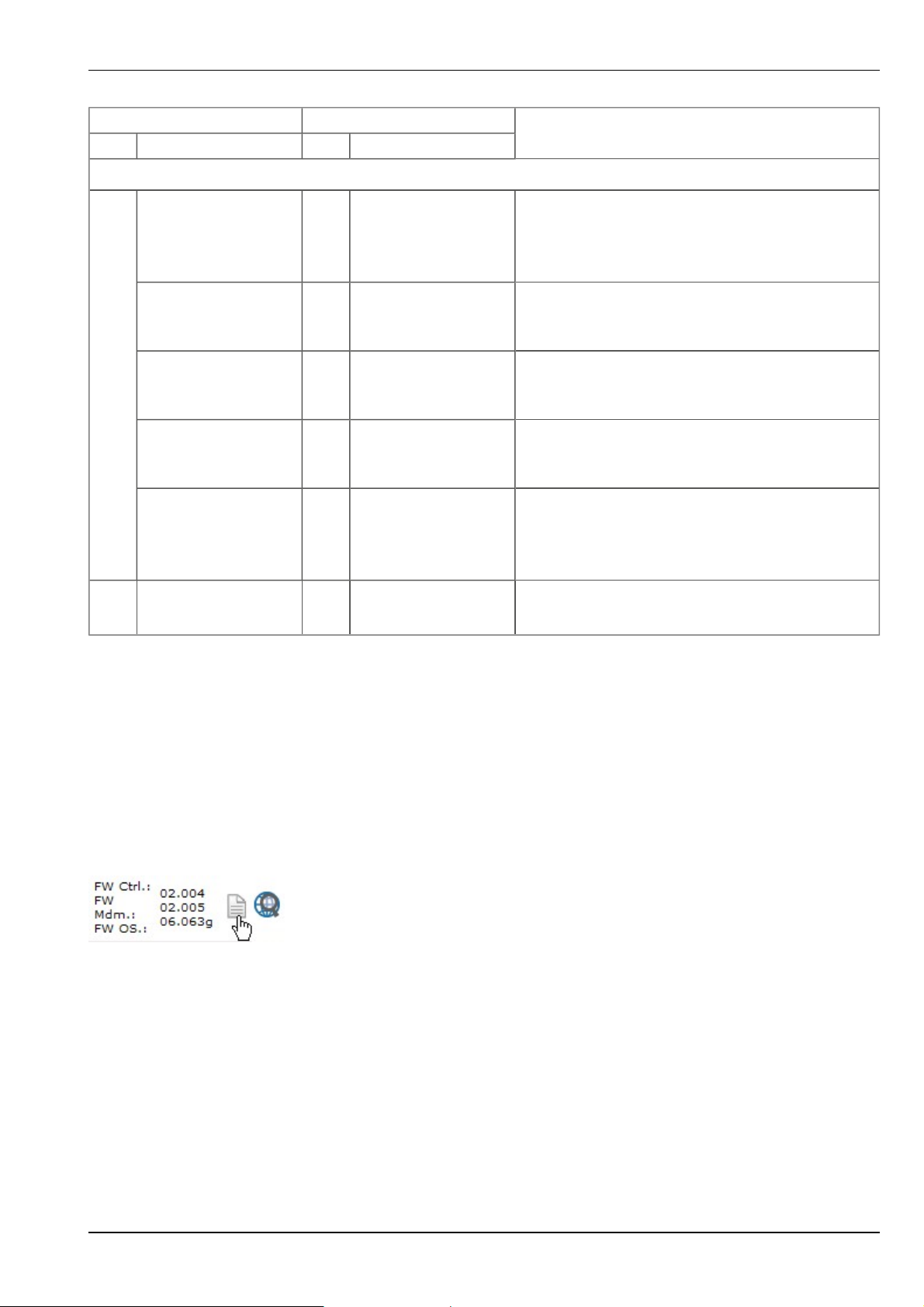
Chapter 13 Troubleshooting and repair
Log entry Parameter
Code Plain text Code Plain text
TCP channel error (2/2)
1200 CHANNEL REFUSED -955 --- The TCP connection has been refused by the
server.
Try again later
CHANNEL HOST
UNREACHABLE
CHANNEL NETWORK
UNREACHABLE
CHANNEL PIPE
BROKEN
CHANNEL TIMEOUT -951 --- Timeout (DNS request, TCP connection, ping
-954 --- No route to the host.
Try again later
-953 --- No network available
Try again later
-952 --- TCP connection interrupted
Try again later
response, etc.)
Try again later
Description
CHANNEL
UNKNOWN
-950 --- Internal error
13.3 Evaluating the device log
13.3.1 Evaluating the device log on the myDataweb server
The last 300 log entries on the myDataweb server can be called up via the button shown below that
is located in the measurement device list. As the log entries are sent to the server in the
transmission cycle in the same way as the measurement data, only the log entries up to the last
server connection are available.
The manual for the server ("myDataweb-Server user manual" 005.002) includes a detailed
description of the evaluation of the device log on the myDataweb server.
13.3.2 Evaluating the device log using myDatanetDeviceConfig
The myDatanetDeviceConfig program can be used to read all of the stored log entries, including
those that have not yet been transferred to the myDataweb server, directly from the myDatasensH2S
1000 via the USB interface.
Rev. 03 79

A more detailed description about the evaluation of the device log using myDatanetDeviceConfig is
included in the user manual for the myDatanetDeviceConfig ("myDatanetDeviceConfig user
manual" 005.004).
80 Rev. 03

Chapter 14 Spare parts and accessories
Chapter 14 Spare parts and accessories
14.1 Assembly sets
Description Quantity Order number
MDN wall mounting 1 206.321
Niro shackle 1 206.325
14.2 Antennas
Note: The use of antennas not listed in this section shall invalidate the Ex approval.
Description Quantity Order number
Antenna 900 FME 1 206.801
Extension cable for Antenna 900 FME 1 206.805
14.3 Accu and battery packs
Description Quantity Order number
Battery packs
BP457A (Li-SOCl2; 51Ah; -10...+40°C operating temperature) 1 206.703
Accu packs
AP424DA (Li-ion; 19,2Ah; -10...+40°C operating, 0 ...+40°C charging
temperature)
1 206.705
14.4 Charging device
Description Quantity Order number
Charger AC15 1 206.701
Snap-on primary plug EU for chargers/power supplies 1 300027
Snap-on primary plug UK for charger/power supply 1 300028
Snap-on primary plug US for charger/power supply 1 300029
Snap-on primary plug AUS for charger/power supply 1 300030
Rev. 03 81

14.5 Cable
Description Quantity Order number
USB15AB 1 206.601
14.6 Other accessories
Description Quantity Order number
MDN Protection casing 1 206.320
Commissioning battery pack for myDatalog/sens Mobile
MDN Magnet 1 206.803
myDatanet Service Kit 1 206.324
MDN Anti-theft device 1 206.322
myDatasens calibration adapter 1 206.813
Calibration set H2S 30ppm 1 206.810
1)
1 305005
1)
The Commissioning battery pack for myDatalog/sens Mobile does not include any accu cells and is only designed with a
USB port as a protective measure that is attached instead of an accu or battery pack.
82 Rev. 03

Chapter 15 Document history
Rev. Datum Änderungen
03 11.04.2013 Kapitel "Declaration of conformity" on page 7
Standards updated
Kapitel "Technical data" on page 11
Technical data of the temperature sensor added
Kapitel "Testing communication with the device" on page 36
Additional explanation about evaluating the "battery" added
Kapitel "Log entries and error codes " on page 74
Breakdown of the error codes added
Chapter 15 Document history
Rev. 03 83


Chapter 16 Contact information
Support & Service:
Microtronics Engineering GmbH
Hauptstrasse 7
3244 Ruprechtshofen
Austria, Europe
Tel. +43 (0)2756 7718023
support@microtronics.at
www.microtronics.at
Chapter 16 Contact information
Microtronics Engineering GmbH
(Headquarter)
Hauptstrasse 7
3244 Ruprechtshofen
Austria, Europe
Tel. +43 (0)2756 77180
Fax. +43 (0)2756 7718033
office@microtronics.at
www.microtronics.at
Microtronics Engineering GmbH
Windthorststrasse 5
63179 Obertshausen
Germany, Europe
office@microtronics.de
www.microtronics.de
Microtronics-UK Ldt.
9b The Shade, Soham, Ely
Cambs, CB7 5DE
United Kingdom, Europe
office@microtronics-uk.co.uk
www.microtronics-uk.co.uk
Rev. 03 85
 Loading...