

Page 1

RAS-M Interface
for
Toshiba TCC-Link
Installation and User Guide
www.microtrol.co.uk
Page 2

Page 3

Contents
1. Important Information............................................................................................................ 2
2. Product Overview ..................................................................................................................2
3. Supplied Parts........................................................................................................................2
4. Connection Details.................................................................................................................3
5. Installation.............................................................................................................................. 3
6. Configuration .........................................................................................................................4
6.1 S1 Bitswitch Function .....................................................................................................................4
Appendix A : Document Revision History ............................................................................... 5
1
Page 4
1. Important Information
All electrical work should be carried out by a competent person and wiring must
be in accordance with the national electrical installation regulations.
Ensure that installation work is done correctly using the information contained in
this manual.
Make all connections securely
not applied to the terminals.
Never modify or repair the Black Pear interface by yourself.
Any attempt to do so will void the warranty.
To dispose of this product, consult your dealer.
so that any outside forces acting on the cables are
2. Product Overview
The Black Pear RAS-M interface provides a TCC-Link connection for new style Toshiba
MIRAI air-conditioner units eg. RAS-07BKVG-E.
It replaces the existing air-conditioner infra-red PCB but still allows manual control using the
I/R remote controller.
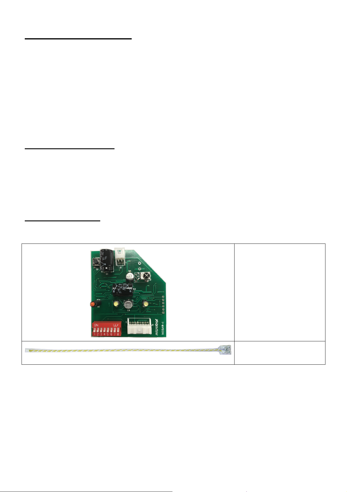
3. Supplied Parts
RAS-M interface pcb
2-wire TCC-Link adapter
cable
2
Page 5
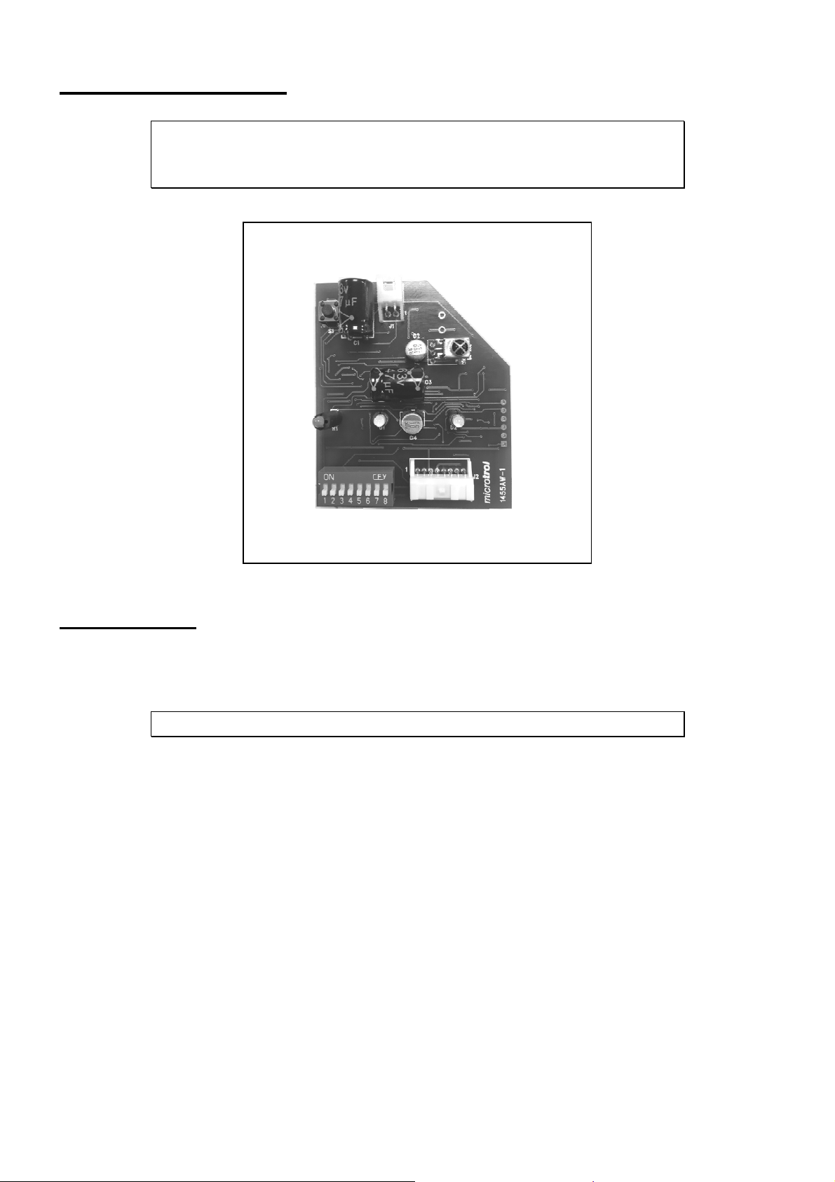
4. Connection Details
cable
(supplied)
All electrical work should be carried out by a competent
person and wiring must be in accordance with the national
electrical installation regulations.
Connect to 2-wire
TCC-Link adapter
Connect to existing
RAS 8-way wiring
harness
5.Installation
The RAS-M interface replaces the existing IR receiver pcb in the RAS unit.
ISOLATE THE RAS UNIT BEFORE REMOVING THE COVER.
1) Carefully remove the existing board in its plastic housing.
2) Separate the housing and remove the board, unplugging the 8-way white connector CN10.
3) Take the RAS interface and plug in both the 8-way connector (J2) and the supplied 2 pin
TCC-Link connector (J1).
4) Fit the RAS interface into the plastic housing and re-assemble the housing ensuring that
both leads exit through the provided side holes.
5) Fit the 2 way TCC-Link terminal block into the space adjacent to the main supply
connector, securing it with the screw provided.
3
Page 6
6. Configuration
6.1 S1 Bitswitch Function
S1-1 On = 100 ohm terminator connected across the TCC-Link lines
Off = No terminating resistor.
Note:- Only one terminating resistor should be enabled per network
S1-2 On = Auto Restart
Off = Start in the OFF condition
Note:- S1-2 overrides the normal auto restart feature
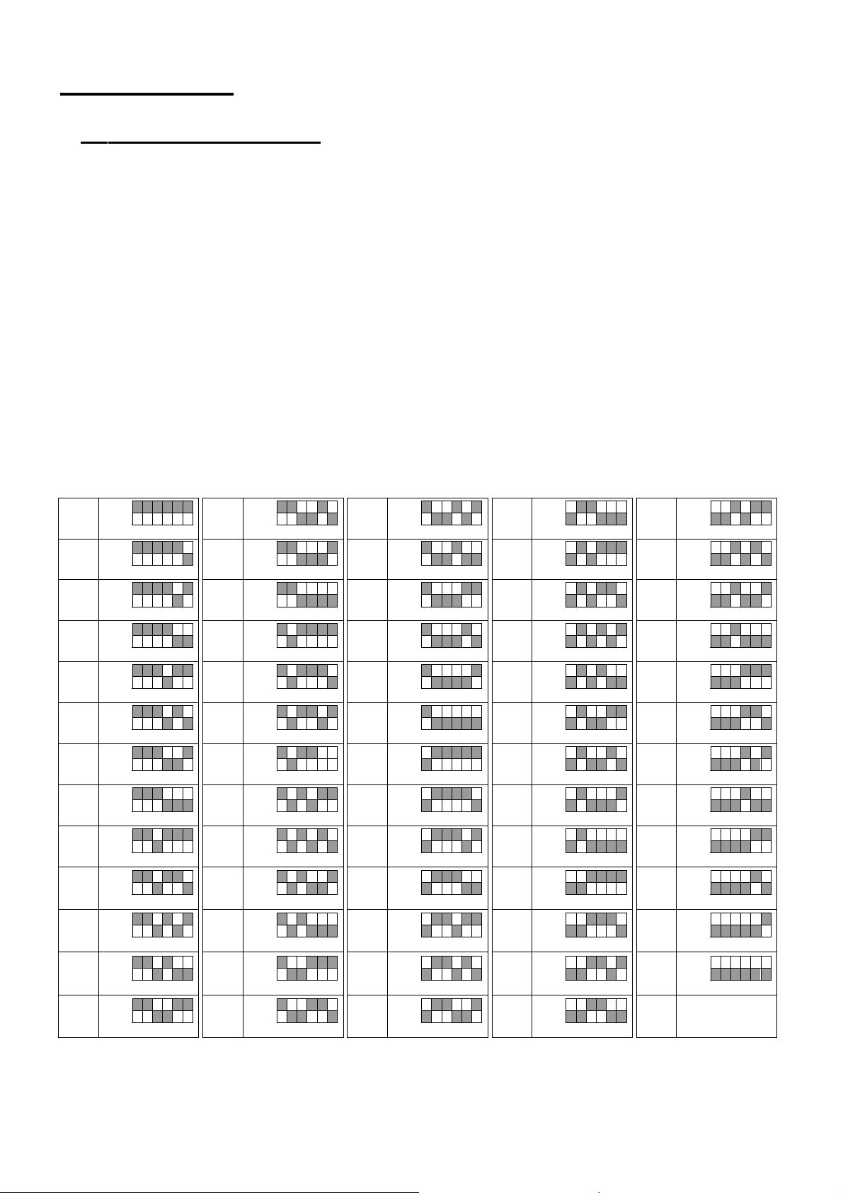
S1-3 to S1-8 Set the address of the unit; S1-3 = MSB : S1-8 = LSB
The address is the binary value of S1-3 to S1-8 plus 1.
(all switches off = 1, all switches on = 64)
1
2
3
4
5
6
7
8
9
10
11
12
13
ON
OFF
ON
OFF
ON
OFF
ON
OFF
ON
OFF
ON
OFF
ON
OFF
ON
OFF
ON
OFF
ON
OFF
ON
OFF
ON
OFF
ON
OFF
3 4 5 6 7 8
3 4 5 6 7 8
3 4 5 6 7 8
3 4 5 6 7 8
3 4 5 6 7 8
3 4 5 6 7 8
3 4 5 6 7 8
3 4 5 6 7 8
3 4 5 6 7 8
3 4 5 6 7 8
3 4 5 6 7 8
3 4 5 6 7 8
3 4 5 6 7 8
14
15
16
17
18
19
20
21
22
23
24
25
26
ON
OFF
ON
OFF
ON
OFF
ON
OFF
ON
OFF
ON
OFF
ON
OFF
ON
OFF
ON
OFF
ON
OFF
ON
OFF
ON
OFF
ON
OFF
3 4 5 6 7 8
3 4 5 6 7 8
3 4 5 6 7 8
3 4 5 6 7 8
3 4 5 6 7 8
3 4 5 6 7 8
3 4 5 6 7 8
3 4 5 6 7 8
3 4 5 6 7 8
3 4 5 6 7 8
3 4 5 6 7 8
3 4 5 6 7 8
3 4 5 6 7 8
27
28
29
30
31
32
33
34
35
36
37
38
39
ON
OFF
ON
OFF
ON
OFF
ON
OFF
ON
OFF
ON
OFF
ON
OFF
ON
OFF
ON
OFF
ON
OFF
ON
OFF
ON
OFF
ON
OFF
3 4 5 6 7 8
3 4 5 6 7 8
3 4 5 6 7 8
3 4 5 6 7 8
3 4 5 6 7 8
3 4 5 6 7 8
3 4 5 6 7 8
3 4 5 6 7 8
3 4 5 6 7 8
3 4 5 6 7 8
3 4 5 6 7 8
3 4 5 6 7 8
3 4 5 6 7 8
40
41
42
43
44
45
46
47
48
49
50
51
52
ON
OFF
ON
OFF
ON
OFF
ON
OFF
ON
OFF
ON
OFF
ON
OFF
ON
OFF
ON
OFF
ON
OFF
ON
OFF
ON
OFF
ON
OFF
3 4 5 6 7 8
3 4 5 6 7 8
3 4 5 6 7 8
3 4 5 6 7 8
3 4 5 6 7 8
3 4 5 6 7 8
3 4 5 6 7 8
3 4 5 6 7 8
3 4 5 6 7 8
3 4 5 6 7 8
3 4 5 6 7 8
3 4 5 6 7 8
3 4 5 6 7 8
53
54
55
56
57
58
59
60
61
62
63
64
ON
OFF
3 4 5 6 7 8
ON
OFF
3 4 5 6 7 8
ON
OFF
3 4 5 6 7 8
ON
OFF
3 4 5 6 7 8
ON
OFF
3 4 5 6 7 8
ON
OFF
3 4 5 6 7 8
ON
OFF
3 4 5 6 7 8
ON
OFF
3 4 5 6 7 8
ON
OFF
3 4 5 6 7 8
ON
OFF
3 4 5 6 7 8
ON
OFF
3 4 5 6 7 8
ON
OFF
3 4 5 6 7 8
The address set by S1-3 to S1-8 is used for both the central TCC-Link address and also
for the Unit address in the Line/Unit addressing mode.
The Line address for the RAS-M interface is always 30.
4
Page 7
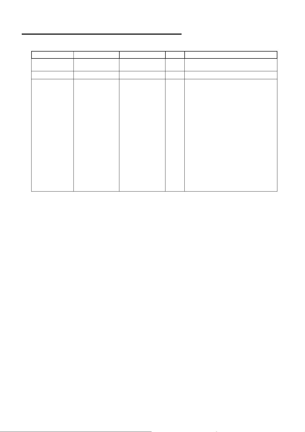
Appendix A : Document Revision History
Date Document Ver Firmware Ver By Comments
19/01/2018 v1.00 v1.13 mcb First version converted from
preliminary instructions to booklet.
5
Page 8

Microtrol Ltd
16 Elgar Business Centre
Moseley Road
Hallow
Worcester
WR2 6NJ
UK
Tel: +44 (0)1905 641910
Email: [email protected]
 Loading...