


Application Monitor
Reference
M a n u a l

TM
Application Monitor
Reference Manual
FlowTrak II is an electronic monitoring system that can help you achieve maximum yields and operate more cost-effectively by
providing the information you need to maintain proper application rates of liquid chemicals and fertilizer. FlowTrak II has been
designed for easy installation and op er a tion. How ev er, since each in stal la tion will vary depending on your equipment, please
take time to fa mil iar ize yourself with this manual and the actual components before beginning. Following the procedures
described in this manual will ensure proper per for mance and help avoid problems or questions once you are in the field.
This manual is written for the FlowTrak II, which may be used for English, Metric or Turf mea sure ment. Please read the manual
carefully and follow the instructions as they apply to your usage.
If you do encounter a problem that cannot be corrected by reviewing this manual, consult your dealer or distributor, or contact
a Micro-Trak technician for assistance.
Toll Free in U.S. or Canada: 800-328-9613
Phone: 507-257-3600 • Fax: 507-257-3001
www.micro-trak.com • trakmail@micro-trak.com
P.O. Box 99
111 East LeRay Avenue
Eagle Lake, MN 56024-0099
© Copyright 2006
Micro-Trak Systems, Inc.
Printed in the U.S.A.
2

Micro-Trak® Warranty
Micro-Trak (herein “Seller”) warrants to the original purchaser (herein “Buyer”) that, if any product or part of the product (herein
“part”) proves to be defective in material or workmanship, upon inspection and examination by Seller, within one (1) year from
the original date-of-purchase, and is returned to Seller with dated proof-of-purchase, transportation prepaid, within thirty (30)
days after such defect is discovered, Seller will, at their option and sole discretion, either repair or replace said part, except that
the warranty for expendable parts, including but not limited to, light bulbs and batteries shall be thirty (30) days from the original
date-of-purchase. Said warranty is valid only when the part has been installed, operated and maintained in strict accordance
with the procedures outlined in the manual. Any damage or failure to said part resulting from abuse, misuse, neglect, accidental
or improper installation or maintenance, unauthorized modification, use with other products or attributable to acts of God, as
determined solely by the Seller, will invalidate the warranty. Said part will not be considered defective if it substantially fulfills
the performance specification. Buyer shall be responsible for all maintenance services, if any, all in strict accordance with the
procedures outlined in the manual. The warranty does not include labor, installation, replacement parts or repairs, delivery of
replacement parts or repairs or time and travel. Said warranty is non-transferable.
THE FOREGOING WARRANTY IS EXCLUSIVE AND IN LIEU OF ALL OTHER WARRANTIES OF MERCHANTABILITY, FITNESS FOR
PURPOSE AND OF ANY OTHER TYPE, WHETHER EXPRESS OR IMPLIED. The Seller’s liability, whether in contract, in tort, under
any warranty, in negligence or otherwise, shall not exceed the return of the amount of the purchase price paid by the Buyer,
and under no circumstance shall the Seller be liable for special, indirect or consequential damages. Seller neither assumes nor
authorizes anyone to assume for it any other obligation or liability in connection with said part. No action, regardless of form,
arising out of the transactions under this agreement may be brought by the Buyer more than one (1) year after the cause of
action has occurred.
Seller agrees to extend the term of the foregoing warranty period should the Buyer return completed warranty registration
information, with dated proof-of-purchase, to the Seller within one (1) year from the original date-of-purchase. All conditions and
limitations of said foregoing warranty, except the term of said foregoing warranty, shall apply. Said term shall be extended to a
total of three (3) years from the original date-of purchase on display consoles and network communication modules, as defined
by Seller, and said term shall be extended to a total of two (2) years from the original date-of-purchase on all other parts, except
that the warranty for expendable parts, including but not limited to, light bulbs and batteries shall be thirty (30) days from the
original date-of-purchase, and except that the warranty for parts manufactured by someone other than the Seller, including but
not limited to, shutoff and control valves, DGPS receivers, memory cards and drives, mapping software, flowmeters and pressure
sensors shall be one (1) year from the original date-of-purchase.
Buyer accepts these terms and warranty limitations unless the product is returned to Seller, via proper distribution channels and
approved return authorization, with dated proof-of-purchase, transportation prepaid, within fifteen (15) days from the date-ofpurchase for refund of the purchase price.
Units under warranty should be sent prepaid, with dated proof-of-purchase, within 30 days of discovering defect, to the address
below:
MAIL and UPS:
Micro-Trak Systems, Inc.
Attn: Service Department
P.O. Box 99 • 111 East LeRay Avenue
Eagle Lake, MN 56024-0099
EXTENDED WARRANTY OPTION
It’s simple! Just complete the enclosed registration card(s) for this
product and mail it in and we’ll extend your warranty for up to three years*, at no additional charge.
MAIL IN YOUR REGISTRATION CARD(S) TODAY!
Registration Card information is for internal use only.
* Some limitations apply. See warranty statement for details.
At Micro-Trak Systems, we believe a product that delivers quality and performance at a low cost is what is needed to help today’s
operator and the operator of the future compete in the world mar ket.
It is our goal to provide operators with a line of electronic equipment that will help build and maintain an efficient and profitable
operation that can be passed on to future generations.
We thank you for your purchase and hope that we can be of service to you in the future.
Micro-Trak Systems, Inc.
3

Table of Contents
Micro-Trak Warranty ............................................................................................................................................................................. 3
Table of Contents .................................................................................................................................................................................. 4
Introduction ...........................................................................................................................................................................................5
Component Parts, Assembly Hardware & Optional Equipment .............................................................................................. 6-7
FlowTrak II System Overview ............................................................................................................................................................. 8
FlowTrak II Wiring Overview ............................................................................................................................................................... 9
Installation ......................................................................................................................................................................................10-16
Mounting the Display Console ........................................................................................................................................................................ 10
Electrical Installation ........................................................................................................................................................................................... 10
Speed Sensor Installation ............................................................................................................................................................................11-12
Magnets ...........................................................................................................................................................................................................11
Attaching Speed Sensor ............................................................................................................................................................................12
Connecting the Speed Sensor Cable ....................................................................................................................................................12
Speed Sensor Options................................................................................................................................................................................12
Mounting and Plumbing Flowmeter ............................................................................................................................................................ 13
Installing Flow Sensor Cable ............................................................................................................................................................................ 13
Remote Run/Hold .................................................................................................................................................................................................14
Connecting the Control Output ......................................................................................................................................................................15
Manual Pressure Relief Valve ........................................................................................................................................................................... 16
Range Adjust Valve .............................................................................................................................................................................................. 16
Care and Maintenance .......................................................................................................................................................................................16
FlowTrak II Console Functions .................................................................................................................................................................................17
Calibration .................................................................................................................................................................................................................18-24
English/Metric Selection .................................................................................................................................................................................... 18
Entering Calibration Values .............................................................................................................................................................................. 19
Speed Cal for Radar or GPS ...............................................................................................................................................................................20
Factory-loaded Calibration Values ................................................................................................................................................................. 20
Determining Speed Calibration ...................................................................................................................................................................... 21
Drive Shaft Speed Sensor Calibration ........................................................................................................................................................... 21
Fine Tuning Speed/Distance Cal Value ..................................................................................................................................................22-23
Entering Target Test Speed .............................................................................................................................................................................. 23
Exiting Calibration ................................................................................................................................................................................................23
Fine Tuning Flowmeter Calibration Value .................................................................................................................................................. 24
Special Calibration ........................................................................................................................................................................................................ 25
Cal Parameters .......................................................................................................................................................................................................25
Factory Settings .................................................................................................................................................................................................... 25
Operation - “Sprayer Monitor” Mode and “Batch” Mode ........................................................................................................................26-29
Console Switches and Buttons ........................................................................................................................................................................ 26
Data Description .............................................................................................................................................................................................26-27
Resetting System Counters ...............................................................................................................................................................................28
Clearing Counters .................................................................................................................................................................................................29
Troubleshooting ......................................................................................................................................................................................................30-34
Message/Warnings...............................................................................................................................................................................................30
General ..................................................................................................................................................................................................................... 31
Checking Individual Components ..................................................................................................................................................................32
Console Inputs .......................................................................................................................................................................................................33
Plumbing Troubleshooting Chart .................................................................................................................................................................. 34
Plumbing Guidelines ...................................................................................................................................................................................................35
Pump Inlet, Agitation, Flowmeter, Pump .................................................................................................................................................... 35
Valve Purpose and Adjustments .....................................................................................................................................................................35
Throttle Valve ................................................................................................................................................................................................ 36
Appendices ................................................................................................................................................................................................................36-42
Appendix A: Optional Speed Sensor Mounting Installation .........................................................................................................37-38
Appendix B: Flowmeter Assembly ................................................................................................................................................................ 39
Appendix C: Radar “Y” Cables ......................................................................................................................................................................... 40
Appendix D: Conversion Chart .......................................................................................................................................................................41
Appendix E: Replacement Parts List .............................................................................................................................................................42
4

Introduction to the FlowTrak II
The FlowTrak II sprayer Monitor, like the original FlowTrak, provides a complete picture of critical spraying functions and is easy to
install and operate. The system monitors and displays:
NEW FEATURES in the FlowTrak II include additional
Volume and Area counters and a new “Tank” feature.
The console can also be programmed to operate either as a
sprayer monitor, or as a batch counter for filling tanks:
SPRAYER MONITOR MODE: When used in typical
spraying operations, the “Control output” should be
programmed to the “HOLd” mode; the Control output can
turn an external valve or pump ON/OFF in response to the
status of the Run/Hold button or the optional remote Run/
Hold sensor, and the Tank counter will show the amount
remaining in the tank. When operating in this mode, the
Tank alarm feature can also be used; it will flash “FILL” on the
display when the tank reaches a (settable) low level. See the
calibration and operation sections for details.
Volume and Area (3
independent sets of
counters record the
amount of liquid
applied and area
covered for up to 3
different jobs. All
3 sets may be reset
independently
Flow Rate (amount
of liquid applied
per minute)
Tank Volume
remaining (new
feature)
Application Rate
(amount applied
per unit area)
FLOW
CAL
MIN
FLOW
TANK
VOL
TARGET
RATE
VOLUME
(1) (2) (3)
VOLUME
MINUTE
TANK
RATE
RUN
HOLD
/
CAL
BATCH MODE: When used in a batching operation or at a
depot where tanks would be filled, the “Control output” can
be programmed in the “FILL” mode. In this mode the Control
output will control a valve or pump used to fill the tank,
turning the valve or pump OFF when the amount reaches a
(settable) level. In this mode, the TANK display will show the
amount that has been pumped into the tank and the tank
alarm is inoperative. This mode requires a fill flowmeter and
possibly a relay adapter if high current levels are required.
II
CALHOLD
1 2 3 4 5
AREA
(1) (2) (3)
DISTANCE
AREA /
HOUR
SPEED
RESET
WIDTH
CAL
SPEED
CAL
TANK
ALARM
TEST
SPEED
Distance traveled (can
be reset independent
of volume & area
counters)
Area per Hour (tracks
work progress)
Ground Speed
5

Component Parts and Assembly Hardware
Before beginning installation, check the carton contents for the following items:
5’ Hall-effect Flow Sensor Cable with
FlowTrak II Console
P/N 17186
Owner’s Manual
P/N 17193
threaded sensor
P/N 13096
(2)
(2)
(2)
(2)
(2)
(2)
(2)
Console Mount Kit
P/N 13181
A. 5’ Hall-effect Speed/Flow
Sensor Cable P/N 13096
D. Speed sensor
mounting bracket
P/N 10013
FM750 GFN Flowmeter
(P/N 11501)
Speed Sensor Kit P/N 01531 (1)
Including items A-F, below:
B. 14” Nylon cable ties (10)
P/N 12910
E. Magnets (6) P/N 12069
(2 in hardware bag)
Power/Speed/Flow/RH/Opt
Harness P/N 17194
C. 15’ 3-Pin Extension Cable
M/P 150 P/N 13207
F. Hardware Bag
P/N 13251
6

Component Parts and Assembly Hardware (cont)
Optional Equipment
Run/Hold Sensor Kit P/N 01535
Including items below:
5’ Run/Hold Sensor Cable
P/N 13226
14” Nylon cable ties (5)
P/N 10045
Flowmeter Kits Available
FM1000SS
Flowmeter
P/N 13187
Kit P/N 01505
FM270 Flowmeter
P/N 14286
Kit P/N 01515
FM10-100
Flowmeter
P/N 14829
Kit P/N 01514
Hardware Bag
P/N 13251
FM1500SS
Flowmeter
P/N 12274
Kit P/N 01506
Speed Sensor
Mounting Bracket
P/N 10013
Magnets - 6
(2 in hardware bag)
P/N 10012
FM500 Flowmeter
P/N 13269
Kit P/N 01500
10’ Extension Cable
M/P 150 P/N 13206
FM750GFN
Flowmeter
P/N 11501
Kit P/N 01501
Relay KitSpeed Sensors
FM750SS
Flowmeter
P/N 10131
Kit P/N 01504
Astro GPS Speed Sensor
P/N 01425
Optional 2-Pin, 3-Pin and 10-Pin Metri-Pack 150 extension cables:
Part No. M/P 2-Pin Part No. M/P 3-Pin Part No. M/P 5/5 10-Pin
13200 5-foot 13205 5-Foot 14363 5-Foot
13201 10-foot 13206 10-Foot 14316 10-Foot
13202 15-foot 13207 15-Foot 14317 15-Foot
13203 20-foot 13208 20-Foot 14364 20-Foot
13204 25-foot 13209 25-Foot 14365 25-Foot
Vansco Radar Speed Sensor
P/N 01527
7
Relay Kit
P/N 17200

FlowTrak II System Overview
OPTIONAL CONTROL
RED
+VES
GND
BLACK
RUN/HOLD
FLOW
SPEED
GRAY TIE
GREEN TIE
YELLOW TIE
BLACK TIE
8

FlowTrak II Wiring Overview
RUN/HOLD SIGNAL
12”
6”
GRAY TIE
ABC
ABC
P/N 13105
DUST COVER
A
2-PIN M-P
3-PIN M-P
150 SHROUD
RUN/HOLD
3-PIN M-P
2-PIN M-P
150 TOWER
A
18 GA. RED
SPEEDFLOW
3-PIN M-P
YELLOW TIE
150 TOWER
ABC
B
150 SHROUD
CONTROL
150 TOWER
B
18 GA. RED
18 GA. WHT
18 GA. RED
18 GA. BLK
3-PIN M-P
GREEN TIE
150 TOWER
ABC
18 GA. WHT
18 GA. RED
18 GA. BLK
POWER
18 GA. BLK
BLACK TIE (4X)
18 GA. RED
120”
ABCDEFGHJ
ABCDEFGHJ
P/N 17194
20 GA. BRN
20 GA. RED
20 GA. ORG
20 GA. YEL
OPTION SIGNAL
SPEED POWER
SPEED SIGNAL
K
10-PIN METRI-PACK 150 SHROUD
10-PIN METRI-PACK TOWER
K
20 GA. GRN
20 GA. BLU
20 GA. VIO
20 GA. GRY
20 GA. WHT
20 GA. BLK
SPEED GROUND
FLOW POWER
FLOW SIGNAL
FLOW GROUND
BATTERY GROUND
BATTERY POWER
18 INCHES
FLOW TRAK - II CONSOLE
9

Installation
Rubber washer
Mounting the Display Console
Select a mounting location which seems most workable,
and that best fits your needs. It should be con ve nient to
reach and high ly vis i ble to the op er a tor. DO NOT IN STALL IN
A POSITION THAT OB STRUCTS THE VIEW OF THE ROAD OR
WORK AREA. Whenever pos si ble, avoid lo ca tions that ex pose
the con sole to direct sun light, high tem per a ture, strong
chem i cals or rain.
Place the mounting bracket in selected lo ca tion, mark holes,
drill 1/4” (7mm) holes and mount bracket with bolts, lockwash ers and nuts pro vid ed. (Use self-tap ping screws if not
prac ti cal to use bolts.) See Illustration 1.
Illustration 1
Bolts
Drill ¼” (7mm)
holes for bolts,
or 3/16“ (5mm)
holes for selftapping screws.
Lockwashers
and nuts
Put rubber washers on carriage bolts and put the bolts
through the bracket holes from the inside out. Loosely
attach the mount knobs onto the bolts. Place console over
carriage bolt heads and tighten knobs to se cure the console.
See Il lus tra tion 2.
Carriage bolts
Mount knob
Illustration 2
CONSOLE END VIEW
Console easily adjusts for
side or dashboard mounting.
Electrical Installation
This section explains how to connect your FlowTrak II to a
12-volt power source.
NOTE: The FlowTrak II must be connected to a 12-volt DC
negative ground electrical system.
Route the power cable of the FlowTrak II harness from the
console to the switched source, plug the connector into the
mating plug for the console and connect the red wire to the
switched power source as shown in Illustration 3 (terminal
Carefully route power
cable to a 12VDC source
Attach Black
Wire (GND) to
Equipment Frame
or wire). Connect the black wire to a screw or bolt on the
equipment frame. Use your test light to locate a terminal or
wire connected to your ignition switch which is “hot” when
the ig ni tion is turned on and “dead” when the ignition is off.
Your FlowTrak II is equipped with a non-volatile memory
which does not require a constant supply of power to retain
daily totals or calibration values. This type of memory
conserves battery power and will not discharge the vehicle’s
battery when equipment is not in use.
Illustration 3
4-amp in-line fuse (Not Provided) required for unprotected circuits
FUSEHOLDER
10
Attach RED wire to
terminal or lead that is
“hot” with ignition on.

Installation (cont)
inimum
S
Test magnet
Speed Sensor Installation
Please Note: If you have purchased an Astro GPS Speed
Sensor or a Vansco radar speed sensor, disregard the
following section on magnetic speed sensors and install
the speed sensor as described in the instructions included
with the unit. You may need an adapter cable to connect
to some radars, see Appendix C.
Locations where the sensor may be installed:
1. Non-driven wheel on tractor, vehicle or implement. This is
less susceptible to errors resulting from wheel slip.
2. Tractor, vehicle or planter drive shaft. This type of
mounting is recommended for trucks, four-wheel drive
tractors or other equipment that has poor or no access to
a non-driven wheel.
Locate the following parts:
• Speed sensor cable (Green body) • Magnets
• Mounting “L” bracket • Cable ties
Magnets
Please read the following information about magnet
spacing and polarity.
The number of magnets that must be used depends on
the size of your tire and where you mount the sensor. On
tractor or implement wheels the general rule of thumb is one
magnet for each wheel bolt (minimum of two, and always an
even number). For drive shafts or small wheels (ATV’s), two
magnets are usually adequate.
Some installations may require that more than two magnets
be installed. To determine the number of magnets required,
measure the distance traveled of one revolution of the
sensor equipped wheel in inches (centimeters).
See the following tables to find the minimum number of
magnets required (always an even number)
English or Turf (inches)
Wheel Circumference 40 80 120 160 200
Number of Magnets 2 4 6 8 10
Metric (cm)
Wheel Circumference 100 200 300 400 500
Number of Magnets 2 4 6 8 10
NOTE: Magnets may be attached mechanically or adhered
with epoxy or other high quality adhesive. When using
adhesive, thoroughly clean the area of dirt and oil.
Illustration 6
The magnets provided by Micro-Trak are marked with a
punched dashed line on the SOUTH pole side of the magnet.
See Illustration 4.
Always use an even number of magnets, and always
alternate the polarities of the magnets as you go around
the wheel hub or drive shaft.
To install, mount the first magnet with the SOUTH pole side
(dashed line) facing toward the hub or shaft. Mount the
second magnet with the NORTH pole side facing toward the
hub or shaft. See Illustration 5.
For proper operation, the magnets must be evenly spaced
around the wheel or drive shaft. The magnets must be at
least 1” apart. See Illustration 6.
Illustration 4
N
Illustration 5
should alternately
North
South
1
6
attract and repel.
North
2
South
5
1” M
11
North
4
3
South

Installation (cont)
Sensor assembly must not
Attaching the Speed Sensor
The magnets are attached to a wheel hub or drive shaft and
the speed sensor is mounted directly over the magnet. When
the wheel or drive shaft begins turning, a speed impulse is
sent to the FlowTrak II console every time a magnet passes by
the tip of the speed sensor. For the speed sensor to operate
properly, the spacing between the magnets and the tip of
the sensor must always remain constant. Before permanently
mounting any parts, be sure that the location you have
selected will meet the requirements shown in Illustration 5.
NOTE: Observe magnet polarities (see previous section).
Connecting the Speed Sensor Cable
The speed sensor cable has a GREEN sensor body and mates
with the 3-pin connector which is marked with a YELLOW
cable tie. The speed sensor and the flow sensor are identical,
but must be connected to the proper harness connector. The
speed sensor always connects to the 3-pin M/P connector with
the YELLOW tie and flow sensor always connects to the 3-pin
M/P connector with the GREEN tie. See FlowTrak II Wiring
Diagram on page 8.
The optional Run/hold sensor also uses the same type of
connector as the speed and flow sensors. However, the
Run/hold sensor has a GRAY tie near the 3-pin connector,
the sensor body is BLACK, and it always connects to the
main harness lead with the GRAY tie. See FlowTrak II Wiring
Diagram on page 8.
Illustration 5
be mounted more than
45° from perpendicular
Bracket must
be rigidly
mounted
45° max
3/8” nuts
Sensor
(Green body)
¼” to ½” air gap
Magnet
SENSOR IDENTIFICATION CHART
SENSOR SENSOR BODY COLOR MAIN HARNESS TIE COLOR
Speed Green Yellow
Flow Green Green
Run/Hold Black Gray
Astro 5 GPS Speed Sensor
Speed Sensor Options
In addition to the standard Hall-effect magnetic speed
sensor, the FlowTrak II may be interfaced with a va ri ety of
other speed sensing equipment. Several options are listed
below.
Astro GPS Speed Sensor
The Astro is an easy-to-install economical alternate to radar
speed sensors. The Astro is available with either a 1 HZ or 5
HZ GPS receiver. The sensor converts GPS signals to a pulsed
speed signal, providing an accurate speed input even in
conditions where radar does not perform well.
Vansco™ Radar Speed Sensor
The Vansco radar speed sensor uses a microwave (radar)
signal to deliver a reliable, accurate speed signal for electronic
equipment. It features state-of-the-art electronic design/
manufacturing, rugged aluminum housing and complete testing
and certification.
Radar Interface
The FlowTrak II may also be interfaced with most popular
radar ground speed sensors. An adapter cable is re quired for
proper interface.
SEE APPENDIX C FOR LIST OF ADAPTER CABLES FOR RADAR.
Vansco Radar
Speed Sensor
GPS Speed Sensor Interface
The FlowTrak II may also be used with most other GPS speed
sensors that output a pulsed signal, such as SkyTrak or
Dickey-John GPS speed sensors. An adapter cable may be
required.
Contact a Micro-Trak dealer/distributor for de tails on
any of these products, or call Mi cro-Trak Systems, Inc. at
1-800-328-9613.
12

Installation (cont)
Mounting and Plumbing Flowmeter
The Flowmeter must be installed in the main boom line
after any strainers or return lines. Se cure ly mount flow me ter
(hardware not supplied) in a vertical position in an area away
from in tense vibration. DO NOT install flowmeter closer than
12” to servo valve or boom shut-off valves. The flowmeter is a
bidirectional meter (exception: Polmac’s 1 1/2”–3”). Liquid can
flow in either direction, but up is preferred, especially at rates
below 5 GPM (19 lpm). Make con nec tions us ing appropriate
fit tings without the use of reducers, elbows or sharp bends
for a minimum of six inches (15 cm) either side of meter. See
Illustration 6. Save plastic plugs to protect flowmeter during
storage. (The flow me ter may need periodic cleaning, so it
should be easy to remove.)
Installing Flow Sensor Cable
With the flowmeter in place, install the flow sensor cable.
The flow sensor cable has a GREEN sensor body and mates
with the 3-pin connector on the main harness marked with a
GREEN cable tie. Screw sensor all the way into hole of flowme ter. Tighten 3/8” jam nut to secure sen sor in place.
Sprayer Line*
Hose Clamps*
“L” Bracket*
Hose Clamps*
¾” NPT Male Fitting*
Hose Clamps*
Illustration 6
Flowmeter
Sensor
(green body)
Locknut
* NOT SUPPLIED
Uncoil flow sensor cable and carefully route it to meet the
main harness flow connector marked with GREEN tie. Align
connectors and press firmly together until locking tab clicks
into place. Secure cable with ties provided. See Illustration
7 and FlowTrak II Wiring Diagram on page 8.
Note: Sensors with GREEN bodies can be used for either
SPEED or FLOW but not for RUN/HOLD.
5’ Hall-effect Flow Sensor Cable with threaded
sensor and male connector (P/N 13096)
Illustration 7
Flow Sensor
Cable Connector
A B C
C B A
Green Tie
Connect flow sensor cable to green-tie console cable.
Main Harness
Flow Connector
13

Installation (cont)
Remote Run/Hold (Requires Kit # 01535)
The run/hold sensor cable has a BLACK body and mates with
the main har ness ca ble having a GRAY cable tie near the 3-pin
M/P con nec tor. Make certain that you install the correct sensor cable and connect it to the correct connector on the main
harness.
Lift Wheel Mounting
Sensor (Black body)
1/8” to 3/8”
(6 mm to 13 mm)
when wheels are up
IMPORTANT:
If not using Run/Hold cable for remote use, make certain a
dust cover with jumper is installed.
• The basic idea is to attach a magnet to a lever or some
part of the equipment that moves when the im ple ment
is raised and lowered. The Hall-effect Run/Hold sensor is
sensitive only to the south pole of the magnet. Install
the magnet with the dashed line facing the sensor.
When the mag net is away from the sen sor, the con sole
will be in HOLD and the area and distance counting
functions will be disabled. NOTE: The run/hold kit
includes a 5’ sensor cable and 10’ extension. You may
re quire additional extension cables which are avail able
in 5 ft. (1.5 m), 10 ft. (3 m), 15 ft. (4.5 m), 20 ft. (6 m) and
25 ft. (7.6 m) lengths.
• You may also use a toggle or other type switch. Sim ply
cut the black jumper wire in the dust cover and splice on
an appropriate length of wire to reach your switch. Do
not connect to a switch with power.
When switch is closed, console is in RUN. When the switch is
open, the console is in HOLD.
Magnet
South
North
Hydraulic Cylinder Mounting
Remote Run sensor on hydraulic cylinder. Magnet and sensor
are in line when equipment is lowered and operating.
Magnet
Run
Position
Sensor
(Black body)
Hold
Position
North
South
5’ Run/Hold Sensor Cable
P/N 13226
14” Nylon cable ties (5)
P/N 10045
Run/Hold Sensor Kit P/N 01535
Including items below:
Speed Sensor
Mounting Bracket
P/N 10013
Hardware Bag
P/N 13251
Magnets - 6
(2 in hardware bag)
P/N 10012
14
10’ Extension Cable
M/P 150 P/N 13206

Installation (cont)
Connecting the Control Output
The “Control” output will drive a load of up to .5 ampere
maximum. For higher currents, either order a Relay Kit, P/N
17200 (15 amp maximum output) or purchase a suitable
relay (maximum .5 amp coil current) and connect to the
CONTROL output as shown in the Illustrations below.
FlowTrak-II Layout
RELAY CONNECTION (USER-SUPPLIED RELAY )
CONTROL
BLACK TIE
GRAY TIE
GREEN TIE
YELLOW TIE
FlowTrak-II Layout
OPTIONAL RELAY KIT ON CONTROL OUTPUT
RUN/HOLD
2-PIN M/P
EXT CABLE
BLACK
GND
CONTROL
RED
+VES
BLACK
FLOW
SPEED
RED
RELAY OR VALVE
NOT SUPPLIED
COIL = 5 AMP MAX
+12 VDC (NOMINAL)
MOTOR OR
SOLENOID
GRAY TIE
BLACK TIE
YELLOW TIE
RUN/HOLD
GREEN TIE
P/N 17200
OPTIONAL RELAY
GND
BLACK
15
RED
+VES
FLOW
SPEED
ORANGE
MOTOR OR VALVE
(V OUT)
(15 AMP MAX)
GROUND
BLUE
+12 VDC (V IN)
(NOMINAL)

Installation (cont)
T
Manual Pressure Relief Valve
If you have a positive displacement pump or a cen trif u gal
pump capable of generating excessive pressure, you must
in stall a pressure relief valve and adjust it to a safe max imum pressure. If a positive dis place ment pump is operated
without a pressure relief valve, damage may re sult to pump
or other plumbing component. See Illustration 8.
Range Adjust Valve
With oversized pumps, it may be necessary to install a range
adjust valve. The range adjust valve will reduce the pump’s
output to the rest of the system. See Illustration 9.
Illustration 8
Pressure
Relief Valve
ee “C”
Tee “A”
Positive Displacement Pumps
Range
Adjust Valve
Tee “C”
Illustration 9
Tee “A”
Oversized Pumps
Care and Maintenance of your FlowTrak II
Console
Store the console in a cool dry location if it will not be used for an extended period of time, such as during the off-season.
As with any electronic equipment, use care in cleaning so that water or other liquids do not enter the case. Thoroughly
flush flowmeter with clean water, install plastic shipping plugs and keep from freezing.
Precautions
• The input pressure on the glass-filled nylon flowmeter FM750 GFN should not exceed 100 PSI (689 kpa).
• Do not expose the flowmeter to liquid temperatures exceeding 130 degrees F (55 degrees C).
• Some chemicals may damage the turbine material. If you are in doubt, contact the chemical manufacturer.
16

FlowTrak II Console Func tions
The FlowTrak II features a large, easy-to-read liquid crystal display, easy-to-use rotary dial and lighted panel for night use.
VOLUME (1) (2) (3): Displays total gallons (liters) or lbs. (kg)
of NH3 applied. May be reset. (Note: VOLUME and AREA
counters work in pairs, if VOLUME counter 1 is reset, it also
resets AREA counter 1.)
VOLUME/MINUTE: Displays total
gallons (liters) of liquid applied per
minute, or lbs. (kg) NH3 per minute.
TANK: In normal operation,
displays gallons (liters) of
liquid remaining or lbs. (kg) of
NH3 remaining. Can also be
used as a Fill flow counter for
batching operations, see Special
Calibration and Operation
sections.
RATE: Displays application rate
GPA(LPH), or lbs. N/acre (kg of N/
hectare).
AREA (1) (2) (3): Keeps a running count of the total acres
(hectares) (thousands of square feet) worked. May be reset.
(Note: VOLUME and AREA counters work in pairs, if AREA
counter 1 is reset, it also resets VOLUME counter 1.)
DISTANCE: Displays distance traveled
in feet (meters). May be reset.
AREA/HOUR: Displays current
work rate in acres per hour
(hectares per hour) (thousands of
square feet per hour).
SPEED: Displays ground speed
in miles per hour (kilometers per
hour).
WARNING LIGHT: Indicates
over or under application of
10% of the Target Rate, or below
min flow or tank set point.
Also lit when in CAL.
Calibration Positions Calibration Positions
FLOW CAL: Used in calibration mode to enter the calibration
value assigned to your flowmeter (See Flowmeter Tag)
MIN FLOW: Used in the calibration mode to enter
the minimum flow rate (GPM/LPM) of the spray boom.
Caution: See page 23 for detailed instructions.
TANK VOL: Used to calibrate the tank volume in gallons
(liters), lbs (kgs) NH3.
TARGET RATE: Used in calibration mode to enter the target
application rate (GPA/LPH) or lbs/acre (kg/hectare) N.
Key Functions:
AUTO
MAN
CAL
RUN/HOLD: Key which changes
between run and hold modes of
operation.
CAL: This key is used to enter &
exit the calibration mode.
RESET
WIDTH CAL: Used in calibration mode to enter the working
width of your sprayer booms or other equipment.
SPEED CAL: Used in calibration mode to enter the speed
calibration number in inches (cm) per pulse.
TANK ALARM: Used to calibrate the tank alarm set point in
gallons (liters), lbs (kgs) NH3
TEST SPEED: Used in calibration mode to enter a test speed
in miles per hour (kilometers per hour).
PROGRAM KEYS: Used to increment and
decrement the different calibration values.
• RESET when not in CAL, clears the selected counter
when held for two sec onds while in hold.
• When in CAL, the “+” key increases and the “-”
decreases the value displayed.
17

Calibration
English or Metric?
The FlowTrak II is capable of displaying in for ma tion in
Amer i can En glish or standard Metric or Turf measurement
units. The FlowTrak II is shipped from the factory programmed
for English. Note that the following procedures will also
load factory default calibration values. To simply change
units without loading defaults, see the “Special Calibration”
section.
METRIC
• To activate the Metric mode, turn power OFF and place
the ro ta ry switch at “AREA.” Hold down both the “CAL”
and “-” keys and turn power ON. See Il lus tra tion 10. The
con sole will display LOAd for two seconds. Once LOAd
is displayed, release the two keys. To “lock-in” Metric
mode you must enter and exit cal i bra tion. You must be
in HOLD to enter Cal. Press and hold the CAL key until
“CAL” icon appears on the display. The con sole is now
in cal i bra tion and Metric mode is selected. Exit CAL by
pressing and holding the “CAL” key until CAL disappears
from the display (ap prox i mate ly 1 second). NOTE: You
must exit CAL to lock in Metric units.
ENGLISH
• To activate the English mode, turn power OFF and
place the ro ta ry switch in the VOLUME position. Hold
down both the “CAL” and “-” keys and turn power ON.
The con sole will display LOAd. Once LOAd is displayed,
release the two keys. To “lock-in” English mode you
must enter and exit cal i bra tion. You must be in HOLD
to enter Cal. Press and hold the CAL key until “CAL”
lights on the display. The console is now in cal i bra tion
and English mode is selected. Exit CAL by pressing and
holding the “CAL” key until CAL disappears from the
display (approximately 1 second). NOTE: You must exit
CAL to lock in English units.
Illustration 10
II
CAL HOLD
FLOW
CAL
MIN
FLOW
TANK
VOL
TARGET
RATE
VOLUME
(1) (2) (3)
VOLUME /
MINUTE
TANK
RATE
RUN
HOLD
CAL
(1) (2) (3)
DISTANCE
RESET
AREA
AREA /
HOUR
SPEED
WIDTH
CAL
SPEED
CAL
TANK
ALARM
TEST
SPEED
NOTE: In metric, the width will have a decimal point, in
English there is no decimal point. Also, changing from
En glish to Met ric mode may change or alter any previously
en tered cal i bra tion values. After switch ing mea sure ment
modes, con firm that all cal i bra tion val ues are correct.
Illustration 11
II
CALHOLD
IN ALL CALIBRATION OPERATIONS:
1. Put system in “HOLD”.
2. Press and hold the “CAL” key for 1 sec ond to select the
cal i bra tion mode. The con sole dis play will display the
“CAL” icon, the currently selected calibration value, and
the red warn ing light will turn on.
3. Turn the rotary dial to the desired “CAL” po si tion. Then
use the “+” or “-” key to adjust the dis played val ue up
or down as needed. Adjust ALL necessary values. See
Illustration 11.
4. Hold the “CAL” key again for 1 sec ond to exit calibration.
“CAL” will disappear from the dis play. NOTE: You must
exit CAL to save changes.
TARGET
Press to enter or exit
calibration mode.
18
VOLUME
FLOW
CAL
(1) (2) (3)
VOLUME /
MIN
FLOW
MINUTE
TANK
TANK
VOL
RATE
RATE
RUN
HOLD
CAL
Red warning light will be
lit when in CAL.
WIDTH
AREA
AREA /
HOUR
SPEED
CAL
SPEED
CAL
TANK
ALARM
TEST
SPEED
(1) (2) (3)
DISTANCE
RESET
Press to increase or
decrease values.

T
Calibration (cont)
Entering Calibration Values
TANK VOL: If using the Tank feature, this setting can be
used to enter the volume of the tank in gallons (liters, lbs.
NH3). Use the “+” and “-” buttons to choose OFF or any value
from 1-65,535. Then when the tank is filled,
the tank counter can be reset to full by simply
turning the rotary switch to the TANK position
and pressing the “+”
button. Depending on
the “UNITS” setting, the
ANK
VOL
TANK
TANK SIZE units will be
either gallons or liters. If “material” is set to NH3, the Tank
Size will be in lbs. or kg. Anhydrous Ammonia (NH3). Note:
the TANK VOLUME remaining feature does not work if the
system is programmed in the (Tank) FILL mode. See page
30 for setup and operation details for the Tank FILL mode.
TARGET RATE: Enter the value for the desired target
application rate in gallons per acre (liters per
hectare) or lbs. of N per acre (kgs of N per
hectare). During operation, the warning light
will flash if the actual application rate is +/10% from the calibrated target rate.
TARGET
RATE
RATE
SPEED CAL: This position is used to calibrate the speed
sensor for ac cu rate
DISTANCE
SPEED
speed and dis tance
CAL
measurement. When
this position is selected,
the display will show THE SPEED CAL value.
TANK ALARM SET POINT: Enter the tank alarm set
point in gallons (liters) or lbs. (kgs) NH3. Use the “+” and
“-” buttons to set the level where the Warning LED starts
flashing and the word “FILL” flashes on the
display. Range is OFF or 1-65,535. When the
tank value drops below
AREA /
HOUR
TANK
ALARM
Note: this feature is inoperative if the system is set up in the
(Tank) FILL mode. See Special Calibration (pages 25-26) and
Tank fill Operation (page 30) for setup and operation details
for the Tank FILL mode.
the set point, the alarms
will notify the user that
the tank level is low.
WIDTH CAL: Enter the effec tive working width of the
entire boom, in inch-
AREA
(1) (2) (3)
WIDTH
the number of nozzles on the boom section
times the nozzle spacing in inches (mm). For
example, if you have 7 nozzles spaced at 20
inches, the working width of the boom section
is 140 inches.
es (meters). Your
CAL
“working” width per
boom section will be
19

Calibration (cont)
Speed Cal for Radar or GPS Speed Sensors
See the following table for SPEED CAL numbers to enter for
various radar models or GPS speed sensors. To fine tune the
SPEED CAL number, see page 22.
Radar or GPS Speed Sensor Calibration
Radars English Cal # in. Metric Cal # in. Hz/MPH
Vansco .150 .38 58.90
Raven .148 .38 59.80
Magnavox .154 .39 57.40
Dickey-john
(NOTE: Dickey-john
radars may be factory
calibrated for any of
these four settings).
GPS Speed
Astro II & 5 .189 .48 46.56
SkyTrak .910 2.31 9.82
SkyTrak 1.50 .38 58.94
Dickey-john .210 .53 42.00
John Deere
(In-cab speed signal) .197 .50 44.70
.149 .38 58.94
.199 .51 44.21
.319 .81 27.64
.518 1.32 17.034
Factory-Loaded Calibration Values
Calibration Factor Measurements Aected Default Values
English Metric
TARGET RATE Application Rate in Auto 10.0 Gallons/Acre 100.0 liters/hectare
TANK VOL Tank alarm or Control Output
WIDTH CAL Area, Application Rate 720 inches 18.00 meters
SPEED CAL Distance, Area, Application Rate, Area/Hour 1.750 inches 4.44 centimeters
MIN FLOW Application Rate, Alarm 0.0 Gallons/Minute 0.0 liters/minute
FLOW CAL Flow/Application Rates, Volume 145.0 pulses/gal 145 pulses/gallon
T ANK ALARM T ank Alarm
20

Calibration (cont)
Determining the Speed Cal (Skip this section if using radar or GPS speed sensor)
For the console to calculate the correct speed and measure
distance accurately, the circumference of the sensor-equipped
wheel must be entered. Determine the circumference of the
sensor-mounted wheel to the nearest tenth of an inch (tenth
of a centimeter) with the fol low ing method:
METHOD: Mark the tire with a piece of chalk and mea-
sure the distance traveled on the ground for one com plete
rev o lu tion. See Illustration 12. For improved accuracy, it
is recommended that you perform this function in field
conditions, measure several revolutions, and take the
average.
Divide the measured revolution by the number of magnets
installed to get your starting SPEED CAL calibration value.
Once calibration of the system is complete, this number
should be fine-tuned for optimum accuracy.
For fine-tuning the SPEED CAL value, see page 22.
Drive Shaft Speed Sensor Calibration
NOTE: If you have mounted the magnetic speed sen sor on
a wheel, skip this step and go on to Fine Tuning Speed/
Distance Calibration Values.
To determine SPEED CAL, measure the distance of one
complete wheel revolution and divide by the number of
magnets installed.
Illustration 12
Because of the difference in wheel-to-drive shaft ra tios, it is
difficult to determine a calibration value for installation on
a drive shaft by measuring a wheel. You must start with an
estimated calibration value and then fine-tune the cal i bra tion.
Any number between 10 and 15 (255 mm to 380 mm) is a
good starting value.
NOTE: For fine-tuning the SPEED CAL value, see next
section.
21

Calibration (cont)
Fine Tuning Speed/Distance Calibration Val ue
PREPARATION:
In order to achieve accurate measurements, each step in this
fine tuning procedure should be performed as precisely as
possible.
1. Once the system is fully installed and calibrated, se lect a
straight tract of ground that is similar to your ac tu al field
conditions and as level as pos si ble.
2. Measure a distance of 1000 feet (500 meters).
Clear ly mark the beginning and end points with flags or
some thing highly visible to the operator.
NOTE: Us ing a course with a different ground sur face, such
as a hard surface road, will re sult in dif fer ent read ings than
actual field con di tions.
Procedure
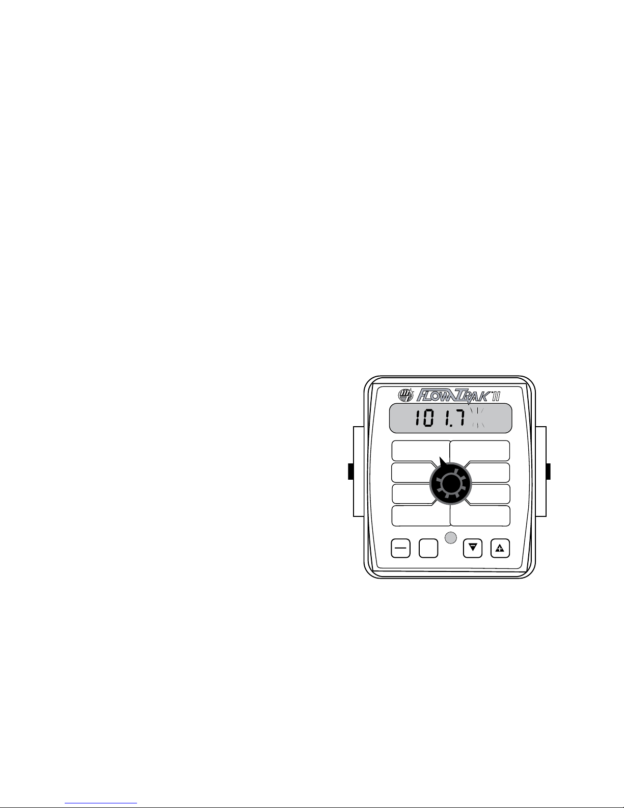
1. With the console turned ON, use the Run/Hold button
to select HOLD mode. The HOLD icon will be displayed.
Turn the rotary dial to the “DISTANCE” position. Be sure
the display shows 0. If not, reset the distance counter by
pressing and holding “RESET” until the display returns to
0 (approximately one second). The word CLEAr will be
displayed when reset is pressed.
5. When the display shows distance (“CAL” is flashing), veri fy wheth er the number displayed is the ex act dis tance
you drove (with in +/- 1 - 2 %). If not, press the “+” or “-”
key to ad just the fig ure to match the dis tance you ac tual ly drove. If the display reads too high, use the “-” key to
lower the dis played value. If the display reads too low,
use the “+” key to raise the displayed value.
6. When the number shown on the display match es (as
close ly as possible) the ac tu al dis tance driv en, you have
ar rived at the cor rect cal i bra tion val ue. If you can not
adjust the displayed distance to exactly match the actual
dis tance driven, adjust the figure as close as possible
to the actual distance. You may check the calibration
number by momentarily pressing CAL. The word CAL
and the SPEED CAL number will appear. Exit “CAL” by
pressing “CAL” for one second.
NOTE: The speed sen sor is now calibrated. To verify proper
calibration, repeat the procedure a sec ond time. Write
down the new speed calibration number and keep it in a
safe place. If the cal i bra tion values are ever accidentally
changed, you can simply re-en ter this num ber.
2. You are now ready to drive the measured course. Pick
a location on the vehicle to use as a marker for starting
and stopping the distance counting function (door
handle, mirror, step, etc.). You should begin driving the
course well ahead of the starting flag and drive past the
ending flag, using the Run/Hold button to start and stop
the counting function. It is not recommended to start
from a dead stop at the starting flag and stop at the
ending flag.
3. Use the Run/Hold button to select RUN mode when
the marker on the vehicle passes the starting flag to
activate the distance counting function. The console
display numbers will increase, adding to the distance
total as you drive. Drive the pre-measured course and
use the Run/Hold button to select HOLD mode, when
the marker on the vehicle passes the ending flag, to
stop the distance counting function. The console display
should read “HOLD”. See Illustration to the right. Stop
the vehicle in a level and safe area and continue with this
procedure.
4. With the rotary dial still at DISTANCE (SPEED CAL), press
and hold the “CAL” key for one second. Once the
con sole is in “CAL,” CAL and the speed calibration value
will be displayed. Momentarily press CAL and the word
CAL will begin to flash and the distance traveled will be
displayed. See Illustration.
FLOW
CAL
MIN
FLOW
TANK
VOL
TARGET
RATE
VOLUME
(1) (2) (3)
VOLUME /
MINUTE
TANK
RATE
RUN
HOLD
CAL
1
RESET
II
CAL HOLD
AREA
(1) (2) (3)
DISTANCE
AREA /
HOUR
SPEED
WIDTH
CAL
SPEED
CAL
TANK
ALARM
TEST
SPEED
22

Calibration (cont)
Fine Tuning Speed/Distance Calibration Val ue (cont)
FLOW CAL: This po si tion is used to cal i brate the flow me ter
for ac cu rate liquid mea sure ment.
Every flowmeter is
calibrated with water
at the factory and
FLOW
CAL
VOLUME
(1) (2) (3)
assigned a “FLOW CAL”
value to make it operate properly with the
FlowTrak II console. This number is stamped
on the metal tag attached to the flowmeter.
See Illustration 13. This is a starting point
only. If your spray solution has a specific gravity or viscosity
that is different than water, flowmeter calibration should be
done for the specific solution (please refer to Fine-Tuning
Flow me ter Calibration on page 24.)
Illustration 13
TEST SPEED: Test speed is a built-in ground speed simulator
that is used in performing pre-field checks. When a typical
operating speed is entered, the FlowTrak II will
respond as if you were actually driving that
speed. It allows you to simulate your monitoring
application, while remaining stationary, to make
certain that all of the
SPEED
TEST
SPEED
perform the intended application. Test speed is cancelled by
exiting CAL. Test speed will not accumulate Distance or Area
measurements.
ENTER TARGET APPLICATION TEST SPEED INTO CON SOLE
Put console in Hold, and press and hold the CAL button for 1 sec.
to enter calibration. Turn rotary switch to TEST SPEED position.
Use the “+” or “-” button to enter target application speed. Do not
exit calibration mode.
Put console in RUN and turn rotary switch to RATE position. The
console should begin monitoring at the simulated test speed.
TEST SPEED will automatically cancel when you exit the CAL
mode or when power to the console is turned OFF.
equipment is operating
properly and that your
monitor can actually
MIN FLOW: The pur pose of this calibration value is to warn the
operator when applying below the recommended minimum
rate for the nozzles. The
minimum flow rate
in gallons per minute
(li ters per minute) based
on the nozzles being used, for the en tire boom
on the sprayer. DO NOT enter the actual flow
of your spray application. For example: If the
min i mum flow rate for the nozzle you are using is .22 GPM at
their minimum recommended pres sure and your boom has 20
nozzles, enter 4.4 as the MIN FLOW value (.22 x 20 = 4.4). This
value should be checked/ changed for each different nozzle
that you use.
MIN
FLOW
VOLUME /
MINUTE
EXITING CALIBRATION: Upon completion of the cal i bra-
tion process, exit calibration by pressing and holding the
CAL button until the RED warning light turns off (ap proxi mate ly three sec onds). Basic cal i bra tion is now com plete.
BEFORE beginning application, confirm that the system is
set up to do the job that you want it to. Please refer to PreField System Checkout to confirm cal i bra tion settings, nozzle
se lec tion and overall system per for mance. NOTE: You must
exit CAL to save any changes.
23
Calibration (cont)
Fine Tuning Flowmeter Calibration Value
This procedure is used to verify and fine-tune the flowmeter
calibration. Every flowmeter is calibrated with water at the
factory and stamped with a calibration val ue. Enter that value
as a starting point and use this pro ce dure to fine-tune that
value for your specific in stal la tion and spray ing application.
This procedure should be re peat ed each time a new solution
is being applied (differ ing so lu tions will have different specif ic gravities and different flow char ac ter is tics) or when the
flowmeter in stal la tion has been altered.
Procedure:
1. Put enough water in the sprayer tank to perform this
test. (Preferably 100 gallons or more. The larg er the
volume of water used, the more accurate will be the
calibration.)
2. Start sprayer pump and turn on booms. Run enough
water to purge all air from lines. Turn off booms but
leave pump running.
3. Turn console rotary selector to the VOLUME po si tion.
Select the counter (1-3) that you want to use. Press and
hold the RESET button until the dis play reads 0 (about 2
seconds).
4. Turn on all booms, and run a known amount of water
(preferably 100 gallons or more).
5. Turn off all booms. Compare the console’s VOLUME
reading with the known amount of water run. See
Illustration. If the two amounts are within one or two
per cent, no fine tuning is required. If the two amounts
are more than two or three percent dif fer ent, con tin ue
with the next step.
6. With the console still in the VOLUME position and in
HOLD, enter calibration (boom switches OFF, hold the
CAL button until red warning light comes on; about one
second). The dis play will show the flowmeter calibration
value and the CAL icon.
7. Momentarily press the CAL button. The CAL icon will
begin to flash and the total volume will be displayed.
*
8. When the TOTAL VOLUME value is displayed, use the “+” or
“-” button to adjust the value to match the amount of
water run.
9. Momentarily press the CAL button. The word CAL and
the flowmeter calibration number will be displayed.
You will notice that the flowmeter calibration value has
changed. Write down the new flowmeter calibration
value. This is your “fine tuned” calibration value, keep it
for future reference.
10. Exit calibration by holding the “CAL” button until the red
warning light goes out (about one second).
The most accurate method to measure the volume of
*
water run is to place a container under EVERY nozzle and
add together the amount from each nozzle. This assures
that 100 percent of the water is collected and that all
nozzles are spraying equally. It is important to perform
this pro ce dure at a flow rate similar to that which will
be used in the field. It is also possible to disconnect the
main boom line and run it to a large measuring container
but a valve must be installed and properly adjusted to
simulate actual field conditions.
II
MANAUTO
CALHOLD
1 2 3 4 5
RESET
AREA
(1) (2) (3)
DISTANCE
AREA /
HOUR
SPEED
WIDTH
CAL
SPEED
CAL
TANK
ALARM
TEST
SPEED
FLOW
CAL
MIN
FLOW
TANK
VOL
TARGET
RATE
VOLUME
(1) (2) (3)
VOLUME /
MINUTE
TANK
RATE
RUN
HOLD
CAL
24

“Special” Calibration
The “Special” calibration mode is used to set up system
parameters that rarely need to be changed or adjusted. To
enter Special Cal, put the system in HOLD, turn the console
OFF, press and hold both the RUN/HOLD button and CAL
button while turning console ON. The console will display
SPEC for 2 seconds to show that the console is in the Special
Calibration mode. Release the RUN/HOLD and CAL buttons.
The CAL icon and Warn LED will turn on. The desired Special
Calibration parameter(s) can then be accessed with the rotary
switch per the illustration below. To exit Special Calibration,
press and hold the CAL button for 2 seconds. The console
will store any changes and revert to normal operation.
NOTE: you must exit Special Calibration to save changes.
Special Cal
II
VOLUME
FLOW
CAL
(1) (2) (3)
VOLUME /
MIN
FLOW
MINUTE
TANK
TANK
VOL
TARGET
RATE
RATE
RUN
HOLD
CAL
RESET
To exit Special Calibration, press and hold the CAL button for
2 seconds. The console will store any changes and revert to
normal operation.
AREA
(1) (2) (3)
DISTANCE
AREA /
HOUR
SPEED
WIDTH
CAL
SPEED
CAL
TANK
ALARM
TEST
SPEED
Units
Material
HOLd/FILL
Units: Choose the system of units desired. Turf units
are the same as English
AREA
(1) (2) (3)
WIDTH
units except Area is in
thousands of square
CAL
feet. Use the “+” and “-”
buttons to choose between EnG (American
English Units), MEt (Metric) and TurF (Turf
units).
Material: Use “+” and “-” buttons to select between
liquid (H2O displayed)
DISTANCE
SPEED
or anhydrous ammonia
CAL
(nH3 displayed). If in
NH3 mode, rates will be
displayed in pounds (kg) actual N and totals
will be displayed in pounds (kg) anhydrous
ammonia (NH3).
HOLd/FILL: “HOLd” selects normal sprayer monitor mode,
“FILL” selects batch mode for filling tanks at a depot. The
selection of HOLd or FILL mode affects both the way the
control output operates and the way the
counters operate. Use “+” and “-” buttons
to select between
AREA /
HOUR
TANK
ALARM
used to open or close a valve based on the RUN/HOLD status.
If the system is in RUN, the Control Output turns ON, if in
HOLD, it will turn OFF. If set in the HOLd mode, the TANK
display will show the amount remaining in the tank and the
TANK ALARM will work as described on pages 19 & 27. In
FILL mode, the optional Control Output energizes when the
console is changed from HOLD to RUN mode and remains
energized until total flow equal to TANK VOL is reached,
then it is de-energized. This may be used to fill the tanks at a
depot or batching operation. It is not recommended to use
the FILL mode at all if operating the system in typical sprayer
monitor applications.
HOLd and FILL modes.
In HOLd mode, the
Control Output can be
NOTE: you must exit Special Calibration to save changes.
The following table describes the special cal parameters and
shows the factory settings. More detailed descriptions follow
the table.
Parameter Description Factory Setting
Units System of units: EnG (English) / mEt (Metric) /TurF (Turf) EnG (English)
Material Choose Liquid (H
Control Mode
“HOLd” - Selects Sprayer Monitor Mode
“FILL” - Selects Batch Counter Mode for Filling Tanks
O or Anhydrous (NH3) H2O
2
HOLd
25

Operation
Operation in the Sprayer Monitor Mode
HOLd selected for Control Mode
(See page 30 to operate the system in the Batch (TANK FILL)
mode.)
FlowTrak II can be operated either as a sprayer monitor or
as a batch counter for filling tanks. (See Special Calibration
Section.)
FLOW
FLOW
TARGET
RATE
II
MAN
1 2 3
RESET
AREA
(1) (2) (3)
DISTANCE
AREA /
HOUR
SPEED
WIDTH
CAL
SPEED
TANK
ALARM
TEST
SPEED
CAL
VOLUME
CAL
(1) (2) (3)
MIN
VOLUME /
MINUTE
TANK
TANK
VOL
RATE
RUN
CAL
HOLD
Make sure your system is properly calibrated before beginning
to monitor your application.
The FlowTrak II system features an easy to use rotary dial.
Simply turn the knob to the desired function. The console
gives a continuous display of the function until another one
is chosen.
CONSOLE POWER/SYSTEM ON/OFF: The system can be
turned ON and OFF by the ignition switch. When the console
is turned on, it will display the number of hours of operation
for 2 seconds, then it will display the software version along
with the “v” icon for 2 seconds before it begins normal
operation.
DISPLAY: During normal operation, the console will display
information selected by the rotary switch position. Typically
the rotary switch will be set on RATE, and the console will
display the Application Rate in units of gallons per acre
(liters per hectare). See DATA DESCRIPTION for additional
information about data displayed.
RUN/HOLD BUTTON: The RUN/HOLD is the master button
for turning all monitoring on and off. This function can
be done either manually with the RUN/HOLD button, or
automatically, using the optional RUN/HOLD sensor kit.
“+” AND “-” BUTTONS: During normal operation, when
the rotary dial is set to Volume 1, 2, or 3 or Area 1, 2, or 3, the
“+” button will select the counter pair to be cleared, and the
“-” button will clear the selected counter pair. See page 28.
WARNING DEVICE: The console is equipped with a RED
warning light. The light will automatically turn on and flash
when the actual application is plus or minus 10 percent of
the calibrated target rate, or if the TANK alarm feature is
activated and the tank is below the set point (display will
also flash “FILL” message). If the light stays on, refer to the
troubleshooting section of this manual. The RED warning
light will also be illuminated when calibration mode is active
on the console.
ROTARY SWITCH: During normal operation, you can
view any one of eight monitored functions by turning the
rotary switch to the appropriate position. The functions that
are active during normal operation are the WHITE boxes.
Calibration positions are identified by the WHITE labeling on
each side of the rotary selector (Please refer to Calibration
section for details).
Turn rotary dial to display desired readout.
DATA DESCRIPTION
VOLUME (1) (2) (3): Displays the total gallons (liters)
applied since the active counter was last reset to zero. When
the FlowTrak II is used in conjunction with NH3, the console
display will read total pounds (kg) of NH3 applied since the
counter was last reset. To select a pair of AREA and VOLUME
counters, use the “+” button to select set 1, 2 or 3, indicated
by the small numbers in the lower right on the display.
DO NOT use the “-” button to select counters because the
button will clear them. (See Resetting System Counters on
page 28.) This active pair of counters may be reset to zero
independent of other system counters.
VOLUME/MINUTE: Displays the actual gallons (liters) per
minute being applied. When the FlowTrak II is used in
conjunction with NH3, the console display will read total
pounds (kg) of NH3 per minute being applied.
TANK: Displays amount remaining in the tank. When the
tank is refilled, and the tank volume has been entered in
Special Cal, the TANK amount can be reset to a full tank by
simply pressing the “+” button for 1 second while the rotary
switch is in the TANK position. The amount in the tank can
be decreased by using the “-” button.
RATE: Displays the actual number of gallons per acre (liters
per hectare) being applied. When the FlowTrak II is used in
conjunction with NH3, and NH3 has been selected in “Special
Calibration”, the console display will read pounds (kg) of
actual “N” per acre (hectare) being applied.
AREA (1) (2) (3): Displays the acres (hectares) covered since
the counter was last reset to zero. The area counters do not
accumulate area when the console is in HOLD. To select a
pair of AREA and VOLUME counters, use the “+” button to
select set 1, 2 or 3, indicated by the small numbers in the
lower right on the display. Do NOT use the “-” button to
select counters because the button will clear them. (See
Resetting System Counters on page 28.) The selected pair of
counters may be reset to zero independent of other system
counters.
DISTANCE: Displays the feet (meters) driven since the
counter was last reset to zero. This counter does not
accumulate when the console is in HOLD. This counter may
be reset to zero independent of other system counters.
AREA/HOUR: Displays acres per hour (hectare per hour)
(thousands of square feet per hour) being covered.
SPEED: Displays the ground speed in miles (kilometers)
per hour.
26

Operation
Operation in the Batch (tank Fill) Mode
To operate in the Tank FILL mode, select the FILL control
mode, see Special Calibration.
Make sure your system is properly calibrated before beginning
to monitor your application.
CONSOLE POWER/SYSTEM ON/OFF: The system can be
turned ON and OFF by the ignition switch. When the console
is turned on, it will display the number of hours of operation
for 2 seconds, then it will display the software version along
with the “v” icon for 2 seconds before it begins normal
operation.
DISPLAY: During Tank FILL operations, the console will
display either the tank level as it is filled (TANK position), or
the flow rate (VOLUME/MINUTE) as selected by the rotary
switch position. Typically the rotary switch will be set on
TANK, as shown in illustration to the right.
RUN/HOLD BUTTON: The RUN/HOLD is used to turn
the FILL operation on and off. Select RUN to start the FILL
operation, select HOLD to stop or pause the operation. A
TANK VOLUME must be entered or the Control Output
will not turn on. When the amount pumped into the tank
reaches the calibrated TANK VOLUME, the Control Output
automatically shuts off. The display will show FULL and the
HOLD icon. If the RUN/HOLD button is pressed, the display
and TANK counter will be cleared and a new FILL process will
start (Control Output turns on).
“+” AND “-” BUTTONS: During Tank FILL operations, the
“+” and “-” buttons can be used to adjust the TANK VOLUME
when the system is in HOLD. This is useful in case the tank is
not completely empty when starting a new FILL process. The
user can enter the “leftover” amount before starting the FILL
process so when the system stops the FILL process, it will not
overflow the tank by the amount leftover.
WARNING DEVICE: The red warning light is disabled in the
Tank FILL mode.
II
MAN
1 2 3
FLOW
CAL
MIN
FLOW
TANK
VOL
TARGET
RATE
VOLUME
(1) (2) (3)
VOLUME /
MINUTE
TANK
RATE
RUN
HOLD
CAL
(1) (2) (3)
DISTANCE
RESET
AREA
AREA /
HOUR
SPEED
WIDTH
CAL
SPEED
CAL
TANK
ALARM
TEST
SPEED
Turn rotary dial to display desired readout.
DATA DESCRIPTION:
VOLUME (1) (2) (3): Not active in Tank FILL mode.
VOLUME/MINUTE: Displays the actual gallons (liters) per
minute being pumped into the tank.
TANK: Displays amount pumped into the tank. When the
amount pumped equals the Calibrated TANK Volume, the
Control Output will shut off.
RATE: Disabled in Tank FILL mode.
AREA (1) (2) (3): Disabled in Tank FILL mode.
DISTANCE: Disabled in Tank FILL mode.
AREA/HOUR: Disabled in Tank FILL mode.
SPEED: Disabled in Tank FILL mode.
ROTARY SWITCH: In the Tank FILL mode, the only active
selections on the rotary dial are the TANK and VOLUME/
MINUTE positions.
27

Resetting System Counters
Not Applicable to the Batch (tank Fill) Mode
The AREA, DISTANCE and VOLUME counters maintain a
running count during operation regardless of the position
of the rotary switch. When any of these counters reach
their maximum capacity, or when you want to start a new
count, the value may be reset to zero by performing the
following routine. Counters may be reset independently of
each other.
1. Put the system in HOLD.
2. Turn the rotary switch to the counter to be reset.
3. To reset distance turn the rotary switch to DISTANCE and
simply press and hold the RESET button until the display
reads zero. The display will show the word “CLEAr” during
this process, and will show 0.0 when reset to zero is
complete.
4. To reset the volume and area counters; there are three
independent AREA counters, paired with three VOLUME
counters. The active pair of counters is indicated by the
small numbers in the lower right area of the display (1,2,
or 3) when the rotary switch is in the AREA or VOLUME
position. Select the pair of counters you want to use by
pressing the “+” button. The small number will increment
each time the “+” button is pressed (from 1 to 3, then rolls
back to 1). DO NOT attempt to select the counter number
by using the “-” button, because that will clear the active
pair of counters if held for 2 seconds. If the “-” button is
accidentally pressed, the console will display “CLEAr” to
alert the user that the counters will be cleared. If the user
continues to hold the “-” button for 2 seconds “CLEAr”
will disappear and be replaced by 0.0, indicating that the
selected pair of counters has been cleared.
To Select a Pair of AREA and VOLUME Counters:
Verify that the desired counter pair is selected, or use the “+”
button to select.
II
CALHOLD
1 2 3 4 5
FLOW
CAL
MIN
FLOW
TANK
VOL
TARGET
RATE
VOLUME
(1) (2) (3)
VOLUME
MINUTE
TANK
RATE
RUN
HOLD
/
CAL
RESET
AREA
(1) (2) (3)
DISTANCE
AREA /
HOUR
SPEED
WIDTH
CAL
SPEED
CAL
TANK
ALARM
TEST
SPEED
Display indicates counter pair #2 is selected
II
MAN HOLD
CALHOLD
2
FLOW
CAL
MIN
FLOW
TANK
VOL
TARGET
RATE
VOLUME
(1) (2) (3)
VOLUME
MINUTE
TANK
RATE
RUN
HOLD
/
CAL
RESET
AREA
(1) (2) (3)
DISTANCE
AREA /
HOUR
SPEED
WIDTH
CAL
SPEED
CAL
TANK
ALARM
TEST
SPEED
Display indicates counter pair #1 is selected
MAN HOLD
CALHOLD
1
VOLUME
FLOW
CAL
(1) (2) (3)
VOLUME
MINUTE
TANK
RATE
RUN
HOLD
/
CAL
MIN
FLOW
TANK
VOL
TARGET
RATE
(1) (2) (3)
DISTANCE
AREA /
SPEED
RESET
II
AREA
HOUR
WIDTH
CAL
SPEED
CAL
TANK
ALARM
TEST
SPEED
28
Display indicates counter pair #3 is selected
II
MAN HOLD
CALHOLD
3
FLOW
CAL
MIN
FLOW
TANK
VOL
TARGET
RATE
VOLUME
(1) (2) (3)
VOLUME
MINUTE
TANK
RATE
RUN
HOLD
/
CAL
RESET
AREA
(1) (2) (3)
DISTANCE
AREA /
HOUR
SPEED
WIDTH
CAL
SPEED
CAL
TANK
ALARM
TEST
SPEED

Resetting System Counters
To Clear Counters
When the desired counter number is displayed, press the
“-” (RESET) button and “CLEAr” will be displayed.
NOTE: holding the “-” (RESET) button for 2 seconds will
clear both the #3 AREA counter and the #3 VOLUME
counter whether the rotary switch is in the AREA or the
VOLUME position.
If the “-” button is released before 2 seconds have elapsed,
the counters will not be cleared and the “CLEAr” message
will be replaced with the previous total.
II
MAN HOLD
CALHOLD
3
FLOW
CAL
MIN
FLOW
TANK
VOL
TARGET
RATE
VOLUME
(1) (2) (3)
VOLUME
MINUTE
TANK
RATE
RUN
HOLD
/
CAL
RESET
AREA
(1) (2) (3)
DISTANCE
AREA /
HOUR
SPEED
WIDTH
CAL
SPEED
CAL
TANK
ALARM
TEST
SPEED
After the “-” (RESET) button has been held for 3 seconds,
the “CLEAr” message will be replaced by 0.0, indicating that
counter pair #3 has been cleared.
HOLD
3
29

Troubleshooting
and start a new FILL operation.
Messages / Warnings
M CAL
This message appears when an error occurs while verifying calibration values
during the power-up. Enter calibration and verify that the calibration values
have not changed and exit calibration. Cycling power will not clear the bad
CAL message. The message can only be cleared by entering and exiting
calibration mode.
Low Power. Check all power and ground connections.
Has loaded Default Cal factors (appears when default calibration factors are
loaded by holding CAL and “-” buttons while turning the console on).
Will ˜ash in display if rotary switch is in RATE position and there is no Speed
signal regardless of all other conditions. Check speed sensor and connections
per Troubleshooting section.
Will ˜ash in display if rotary switch is in RATE position and should have ˜ow
(In Run, some booms on, speed greater than 0) but no ˜ow is detected. Check
˜owmeter and ˜ow harness connections per Troubleshooting section.
V
Rotary switch in any position, FILL will ˜ash if tank level is equal to or less than
tank set point. Fill tank and reset TANK counter by setting the rotary switch at
the TANK position and pressing the “+” button for one second. Check to make
sure TANK set point is properly calibrated.
Warn LED ˜ashes when the Rate error is over 10% or Volume/Minute is below
the Minimum, or Tank is less than Tank Set Point. It is on steady when in CAL
mode or SPECIAL CAL mode or Test Speed.
Special Calibration mode is active. Appears when entering Special Calibration
mode (hold RUN/HOLD and CAL buttons while turning console on).
On startup, the “V” is displayed next to the software version #. (Console hours
displayed ÿrst.)
The message alerts the user that the currently selected counter will be cleared
if held for 2 seconds. Also serves as a reminder to use “+” button to select
counters.
Counters (DISTANCE or AREA or VOLUME) have exceeded their maximum.
RESET (see pages 27-28) to clear counters and resume counting.
Turns on (in Tank FILL mode) when the amount pumped into the tank is equal
to the calibrated TANK Volume. Press Run/Hold button momentarily to clear
30

Troubleshooting (cont)
General
All FlowTrak II consoles and flowmeters are tested prior to
packaging, so unless there has been damage in shipment
you can be confident that everything will be operational
when you receive it.
However, if you do encounter a problem that appears to be
related to equipment failure, PLEASE DO NOT OPEN THE
CONSOLE. Your system is protected by a warranty, and
Micro-Trak will gladly correct any defect.
Problems can be the result of mistakes in installation or
operation. Before returning any parts for service, carefully
check your installation and review the operating instructions.
For easy-to-follow guidelines, refer to the troubleshooting
section which follows.
CONSOLE APPEARS DEAD
Using your test light, check for 12 volts at the power source.
Also check for damaged power cable or reversed terminals.
(Console requires 12 volts for proper operation).
SPEED IS ALWAYS ZERO OR ERRATIC
Check for properly calibrated speed cal number.
Review speed sensor installation. Check for proper mounting,
alignment and spacing of speed sensor in relationship to
magnet assembly. Make sure magnet polarities are alternated.
Also check cable for breaks or incomplete connection. For
more suggestions on solutions to speed problems, see Halleffect sensors and console inputs on pages 34-35.
DISTANCE COUNT IS INACCURATE
Speed cal number was incorrectly calculated or entered.
Review calibration, re-adjust and test.
AREA COUNT IS INACCURATE
Working width or wheel circumference was measured
incorrectly, or speed cal number was calculated or entered
incorrectly. Go back through the original procedures, make
changes, and test for acre (hectare) count again. Verify
accuracy with formula:
Acres = Distance x Width in feet/43560
Hectares = Distance x Width in meters/10,000
Thousands of square feet = Distance x Width in feet/1000
NO READOUT OF GALLONS (LITERS), OR GALLONS
(LITERS) PER MINUTE
Check to see that the sprayer pump and equipment are
operating properly. If liquid is moving through the line,
check the flow sensor to be sure it is screwed all the way into
the flowmeter.
Check to see that a FLOW CAL number has been entered.
Also check cable for breaks or incomplete connection.
If the flowmeter is new or has not been used for a long period
of time, the turbine may be sticky. Flushing the system out
with water should make the turbine spin freely.
Flow rate may be too low to register a reading, or foreign
material may be lodged in the flowmeter.
Total liquid used is inaccurate
This may result from an incorrectly-entered “FLOW CAL”
value. Check the number stamped on the flowmeter tag,
and be sure this is entered in the console’s “FLOW CAL”
position. If the meter has been used for some time, wear
may have changed the Flow Cal value. See Fine-Tuning
Flowmeter Calibration on page 24.
Check the mounting position of the flowmeter. With lower
flow rates, the meter should be mounted vertically. Also
check to see that the flow sensor is screwed all the way into
the flowmeter.
Other causes may be inaccurate sprayer tank markings, a
flow rate too low to register, or foreign material lodged in
the flowmeter.
CONSOLE IS ERRATIC IN OPERATION
If you have a two-way radio, it may be mounted too close to
the console. Keep all FlowTrak II cables away from the radio,
its antenna and power cable.
Ignition wires may be causing the console to malfunction.
Keep FlowTrak II cables away from ignition wires, or install
ignition suppressor.
Reroute all cable away from electric solenoids, air conditioning
clutches and similar equipment.
DISPLAYED MEASUREMENTS DO NOT MAKE SENSE
The console may be in the incorrect measurement mode
(English or metric). See page 18 for instructions.
DISPLAY READS “OFL”
DISTANCE, AREA, and VOLUME counters read OFL when
they have exceeded their maximum count. Reset to zero to
resume counting.
31

Troubleshooting (cont)
Checking Individual Components
CONSOLE
The only way to field test a console is to con nect it to a
harness on a vehicle with a known working console or install
it on an E-POP (Elec tron ic Point of Purchase) dis play stand.
HARNESS
The harness can be checked using an ohm me ter or continuity
tester. The main wiring diagram shows the pin out of all
connectors. See page 8.
ELECTRICAL INTERFERENCE
Erratic operation of the system may be the result of electrical
interference from ignition wires or inductive loads (electrical
clutch, fan, solenoid, etc.). Always try to route wires as far
away from suspect areas as possible. If problems occur, you
may need to relocate the console and/or wiring harness, or
install a noise suppressor.
POWER
Check power source with the MT-101 or a test light. If there
is no pow er, trace cable toward battery look ing for breaks.
Also check any fuses or circuit break ers that supply pow er to
the console.
ACCESSORY POWER
The speed, flow and run/hold cables all have an ac ces so ry
power wire. Check for 12 volts between B (usu al ly white) and
C (usually black) of these con nec tors. If power is not present,
make sure the ac ces so ry pow er wire is not open or shorted
to ground or to another wire. If this wire has a prob lem, the
con sole may ex hib it erratic behavior or not function at all.
RUN/HOLD HALL-EFFECT SENSOR
Caution: Improper connection or voltage could damage the
Hall-Effect sensor. The Hall-effect sensor works similar to a
reed switch, but requires power in order to function. This
particular type of Hall-effect sensor “closes” when near the
south pole of a magnet and is otherwise “open”.
Ground pin C (black) and connect clean 12 volts to pin B
(white) of the Hall-effect sensor cable. Connect the positive
lead (red) of an ohmmeter or continuity tester to pin A (red)
and the negative lead (black) of the ohmmeter or continuity
tester to pin C (black) of the Hall-effect sensor cable.
Holding the tip of the sensor up to the south pole (face with
dotted line) of a magnet should result in a very low resistance
(around 300 ohms). Taking the sensor away from the magnet
should result in a very high resistance (infinite).
MAGNETIC HALL-EFFECT SPEED AND FLOW SENSORS
Caution: Improper connection or voltage could damage
the Hall-effect sensor. The Hall-effect sen sor works similar
to a reed switch, but re quires pow er in order to func tion.
Also, this par tic u lar type of Hall-effect sen sor re quires al ternat ing magnetic po lar i ties in or der to switch. This means that
the north pole of a mag net will “open” the Hall effect and the
south pole of a magnet will “close” the Hall effect.
Ground pin C (black) and connect clean 12 volts to pin B
(white) of the Hall-effect sensor cable. Con nect the positive
lead (red) of an ohmmeter or con ti nu ity tester to pin A (red)
and the negative lead (black) of the ohmmeter or continuity
tester to pin C of the Hall-effect sensor cable.
Holding the tip of the sensor up to the north pole of a magnet
should result in a very high re sis tance (in fi nite), while holding
the tip of the sensor up to the south pole of a magnet should
result in a very low resistance (around 300 ohms).
VANSCO RADAR SPEED SENSOR
Carefully check your installation and operating instructions.
The following are tips for troubleshooting;
1. Disconnect the radar adapter cable from the console
harness.
2. Check for 12 VDC between pins B and C of the main harness connector (yellow tie). If not present, console or
harness may be defective.
3. Using a jumper wire (paper clip bent into a “U”), rapidly
short together positions A and C of the main harness
speed connector (yellow tie) several times. The console
should respond with some reading. If not, the console or
harness may be defective.
4. Reconnect the radar adapter cable to the main harness
speed connection (yellow tie).
5. Disconnect the radar from the radar adapter cable.
6. Check for 12 VDC between pins 1 and 3 of the radar
adapter connector. If it is not present but was present in
step 2, the radar adapter cable may be defective.
7. Using a jumper wire (paper clip bent into a “U”), rapidly
short together positions 2 and 3 of the radar connector
(round 4-pin) several times. The console should respond
with some speed reading. If not but had a reading in step
3, the radar adapter cable may be defective.
RUN/HOLD JUMPER DUST COVER
To test for proper continuity on the jumper wire, connect the
ohmmeter to the pins of the dust cover with the jumper wire.
There should be continuity — near zero ohms.
8. If the system passes all above tests, the radar may be
defective.
32

Troubleshooting (cont)
Console Inputs
If there is no response from any of the following tests, refer
to the main wiring diagram to locate the next connector in
line to ward the con sole and repeat the test at that con nec tor.
If there is a response at that connector, the problem may be
in the cable between the two connectors (or the con nec tors
themselves).
SPEED INPUT
Turn rotary switch to speed po si tion and dis con nect the
speed sensor (yel low tie) from the main harness. Check for
12 volts between pins B (white) and C (black) of the main
harness speed cable (yellow tie). Using a clip lead or other
jumper wire (such as a paper clip bent in a “U”), several times
rap id ly short to geth er pins A (red) and C (black) of the 3-pin
connector (See Illustration 14). The console should respond
with some speed read ing.
FLOW INPUT
Turn rotary switch to VOLUME/MINUTE and disconnect the
flow sen sor (green tie) from the main harness. Check for 12
volts be tween pins B (white) and C (black) of the main harness
flow cable (green tie). Using a clip lead or other jumper wire
(pa per clip bent in a “U”), several times rapidly short together
pins A (red) and C (black) of the 3-pin connector. The con sole
should re spond with some flow rate reading.
FLOWMETER
Shaking the Flowmeter end to end should pro duce a “rattling”
sound (shaft end play). Blowing in the meter from either end
should spin the turbine freely. If the turbine spins freely but the
meter will not register flow with a known working sensor, the
turbine may be defective. See Flow me ter Assembly and clean ing
on page 43 for details.
PLUMBING
Proper plumbing is a very important factor in obtaining
optimal performance from your FlowTrak II system. The chart
on the next page will help you determine what area of the
plumbing may be causing your problem. At this point, it is
assumed that your plumbing basically matches that of the
system diagram and that the flowmeter is installed correctly
and is functioning properly. In addition, make certain that
you have selected and installed the correct spray tips for
the application, speed and spray rate that you intend to
maintain. Don’t forget the obvious such as leaky fittings and
hoses, pinched hoses and plugged or worn nozzles. If you
need more detail than the chart provides, please refer to
Plumbing Guidelines on pages 36-38.
Illustration 14
CBA
Three-Pin Connector
REMOTE RUN/HOLD INPUT
Disconnect the remote run/hold sensor (or jumper cover)
from the main harness.
Check for 12 volts between pins B (green) and C (violet) of
the main harness remote run/hold cable (grey tie). Placing a
clip lead or other jumper wire (such as a paper clip bent in a
“U”) between pins A (blue) and C (violet) of the main harness
run/hold connector (grey tie) should turn off the “HOLD”
icon on the console display. Removing the jumper should
turn on the “HOLD” icon on the console display.
33

Plumbing Troubleshooting Chart
SYMPTOM POSSIBLE CAUSE POSSIBLE SOLUTION
Loses pressure • Pump Air-lock • Clean strainer
• Larger hoses
Little or no pressure
adjustment
Pressure won’t go high
enough
• Too much restriction in servo loop •
• No sharp bends
• Pump starved or too small
• Too much agitation
• Throttle, range adjust or pressure relief valves
• Larger hoses
• Reduce agitation
• Adjust
Pressure, Speed and
Spray Rate don’t check
out according to charts
greatly
• Inaccurate pressure reading
• Dirty or worn tips
• Sagging or kinked hoses
• Throttle valve too far closed
• Pump starved or too small
•
each boom.
• Clean or place
• Support or replace hoses
• Adjust throttle and range valves
• Larger hoses
• Larger pump
• Clean strainer
34

Plumbing Guidelines
General
In order for your sprayer to function properly, it must be
correctly plumbed. This section will explain the purpose
of each component, list some problems it can cause and
recommend some possible solutions to those problems.
A word about pressure drops: All hose, valves and fittings
(especially elbows) cause undesirable pressure losses. Keep
hoses as large as practical. Don’t use longer hoses than
necessary. Avoid bends whenever possible. Use as few
fittings as possible. Use full port valves or the next larger size
valve. Long hoses should be supported to avoid sagging and
kinking. Many spray tip manufacturers have charts showing
pressure drop for various fittings and hose sizes.
Now let’s break the system into four sections and cover each
one separately. The four sections are the pump inlet line, the
agitation line, the flowmeter (boom) line, the servo line and
the pump itself.
PUMP INLET
The hose connecting the tank to the pump should be at
least as large as the pump inlet port. In most cases 11/4” is a
good size. The valve in this line is for complete tank shut-off
only and should always be fully open during operation. If
this hose is too small or the valve is partially closed, you may
not be able to reach your high end goals and pump damage
could occur.
AGITATION
The size of the agitation line is dependent upon the amount
of agitation required which is determined by the size of the
tank and the type of chemical being used. In most cases a 1”
hose is large enough.
FLOWMETER
The line feeding the flowmeter and the boom shut-off valves
should be at least as large as the flowmeter. The size of
lines going from the shut-off valves to each boom section
depends on the flow rate of each boom.
PUMP
The pump must have enough capacity to satisfy the agitation,
servo and flowmeter sections of the plumbing. The following
example will take you through the steps involved.
Example: Let’s say our example sprayer has a 300-gallon
tank with a Spraying Systems 6290 SC-8 Jet
Agitator. The agitator uses 10.2 GPM at 40 PSI.
The sprayer has a 40’ boom with a total of 12
tips. We plan to put on a 25 GPA at 5 MPH and in
some areas of the fields we may want to increase
our rate to 30 GPA and in other areas decrease to
15 GPA. After checking the tip charts we find that
a TK-5 Floodjet has a range of 14.9 to 30 GPA at 5
MPH. According to the charts, to get 30 GPA at 5
MPH with a TK-5, the pressure must be 40 PSI. At
40 PSI a TK-5 will spray 1.0 GPM. So, 12 tips at 1.0
GPM each is a total of 12 GPM.
Now Let’s Add Everything Together.
Agitation 10.2
Spray tips 12.0
Servo 5.0
27.2 Total GPM
The above addition shows that the system needs
27.2 GPM at 40 PSI. If we add a 10% margin (27.2 x 1
= 2.72 and 27.2 = 29.92), we have about 30 GPM. To
be sure we have enough volume, the pump should
be able to deliver 30 GPM or more at 40 PSI.
Valve Purpose and Adjustments
TANK SHUT-OFF VALVE
The tank shut-off valve is for convenience only. It allows you
to work on the plumbing without draining the tank. It should
always be fully open during operation.
AGITATION SHUT-OFF VALVE
The agitation shut-off valve is mostly for convenience. It
allows you to work on the plumbing without draining the
tank. It should normally be fully open during operation.
PRESSURE RELIEF VALVE
The pressure relief valve is used to avoid excessive pressure
when the booms are turned off. Start with the handle
screwed mostly out. Slowly bring pump up to operating
RPM (make sure pressure does not go too high). Now slowly
screw handle in until maximum desired pressure is reached.
Lock handle in place with locking nut or collar.
RANGE ADJUST VALVE
The range adjust valve is required when the pump is much
larger than necessary. When the range valve is opened, some
of the liquid will be bypassed around the pump to avoid
“overloading” the rest of the system. The setting of the range
adjust valve is determined by the throttle valve. Start with
the range valve fully closed. If the throttle valve needs to be
more than two thirds closed, open the Range valve slightly.
THROTTLE VALVE
The throttle valve limits your high end to maximize servo
performance. Start with throttle valve fully open.
Example: With the throttle fully open, you may be able to
get 50 GPA at 5 MPH when you only want 25 GPA.
Therefore, close the throttle until your high end
A needle valve is Spraying Systems Type 12690
If the throttle valve is closed too much, PSI may
has dropped from 50 GPA to about 30 GPA.
or 12795. A ball valve may be used but is more
difficult to adjust and keep adjusted. Do not
install a pressure regulator or relief as a throttle
valve.
fluctuate greatly.
35

Appendices
36

Speed Sensor
FABRICATED BRACKET
Hub
Rim
Appendix A
Optional Speed Sensor Mounting Installation
Implement Wheels
1. Secure magnets mechanically or with epoxy.
and Bracket
2. Rigidly mount sensor mounting bracket to the wheel
assembly. Cut or bend “L” bracket as required for proper
positioning of sensor.
3. Install sensor, adjust to correct spacing (1/4” to 1/2 “ or 6
to 13 mm is recommended), and secure with 3/8” locking
nuts. See Illustration at right.
Front Tractor Wheel
1. Magnets may also be secured with a cable tie and an
adhesive such as epoxy.
2. Mount the speed sensor bracket to a part of the wheel
assembly that does not change position to the hub when
the wheels are turned. If the “L” bracket provided cannot
be bent and mounted to properly position the sensor,
make a bracket similar to the one shown at right.
3. Install sensor, adjust to correct spacing (1/4” to 1/2 “ or 6
to 13 mm is recommended), and secure with 3/8” locking
nuts. See Illustration below.
Speed Sensor
¼” Bolts,
Lockwashers
and Nuts
Speed Sensor
Cable Tie
ATV Wheels
Two mounting examples are illustrated.
1. Using one cable tie (ribbed side toward magnets), secure
two magnets to the wheel hub so they are exactly
opposite each other. Alternate the magnets’ polarities.
2. Cut and bend sensor mounting bracket as needed and
rigidly mount.
3. Insert sensor, adjust spacing (1/4” to 1/2” or 6 to 13 mm)
and secure with 3/8” locking nuts.
CAUTION: Make sure valve stem cannot make contact with
sensor or bracket.
Top View
Tap thread for
Cable Tie
Optional section
of hose to
protect cable
3/8” hole
for sensor
bolts or weld
Sensor
3/8” nut
3/8” nut
Cut Bracket
to Clear Rim
Magnet
Plastic
Cable
37
Tie
Rim
Hub
ATV Wheel Mount
Sensor Bracket
Axle
Nut
Swing Arm
Cut and Bend
Bracket as
Required
Magnet
Alternative ATV
Wheel Mount
Hub
Clamps
Tube
Axle
Metal
Hose
Fork

T
Appendix A (cont)
Optional Speed Sensor Mounting on Drive Shaft
NOTE: This is an optional method generally used on
pickups or custom vehicles. It may also be nec es sary
on any other vehicles where ac cess to the wheels is
lim it ed. This in stal la tion requires a fine tuning procedure,
see pages 19-20.
Determine the best location for the magnets on drive shaft
according to which is the most practical spot to attach sensor
mounting bracket. This position should be no more than 12”
(.30 meters) behind the front U-joint. For best results, mount
“L” bracket to transmission and mount magnets on drive
shaft as close to transmission as pos si ble. This will en sure
prop er alignment if drive train shifts under heavy loading.
Two magnets are required for proper Hall-effect speed
sensor operation. Position them exactly opposite each other
(180 de grees apart). The polarity (north and south poles)
detect ed by the Hall-effect speed sen sor must alternate as
the shaft is turned. The magnets provided by Micro-Trak are
marked with a dashed line on the SOUTH pole side of the
magnet.
Sensor Body
(Green)
• Attach magnets onto drive shaft, one NORTH pole side
out and the other SOUTH (dashed) pole side out, by
wrapping ca ble tie around shaft and magnets. Position
each mag net so that its longest dimension moves in
the di rec tion of rotation. Pull cable tie tight and trim
off excess. An adjust able, non-magnetic (stain less steel)
band clamp may also be substituted.
• Attach sensor bracket to vehicle transmission. See
Illustration below. Use either the short or long end of
the brack et as a base.
• Turn one locking nut onto threaded sensor and in sert
sensor into large hole selected on mount ing brack et.
Turn on remaining locking nut. Set sensor to proper
distance from magnets (1/4” to 1/2”, or 6mm to 13mm).
When distance is set, tight en nuts to lock sensor in
place.
• Secure sensor cable to frame with cable ties. Place first tie
as close to sensor assembly as possible.
See SPEED CAL on page 18.
Fasten Sensor Bracket with
Existing Transmission Bolts
or Rigidly Attach with Clamps.
¼” to ½”
(6mm to 13mm)
Spacing
ransmission/ Transfer Case Drive Shaft
Magnets Positioned
180° Apart
38

Appendix B
Flowmeter Assembly
IMPORTANT: Opening the flowmeter will void the Flowmeter
Calibration value assigned to your unit. However, you may
need to take the flowmeter apart for periodic cleaning or
to remove an obstruction.
If you can shake the flowmeter from end-to-end to produce
a “rattling” sound (shaft-end play), or if you can blow into the
meter from either end and cause the turbine to spin freely,
your flowmeter does not need cleaning. If you cannot hear
the “rattling” sound or get the turbine to spin freely, your
flowmeter needs to be cleaned. See Illustrations below for
reassembly instructions.
OPENING THE FLOWMETER
Cut the calibration tag retaining wire. Remove the screws
and disassemble the flowmeter. Do not attempt to remove
the sleeve bearings from the flowmeter housing.
Use warm water and if necessary, a mild detergent and a
soft bristle brush to clean all parts. Do not use solvents or
diesel fuel to clean the flowmeter. A magnet works well for
removing fine metallic particles from the turbine.
Inspect all parts. Check for excessive bearing or shaft wear.
The shaft will wear shorter until the turbine drags on the
housing. When the shaft is worn to the point of drag, the
turbine must be replaced.
On a flat surface, place each housing half on end. Set and
spin the turbine in each half. It should spin freely. If it does
not spin freely, remove the turbine, wipe the shaft and try
again. If is still does not spin freely, the shaft or bearings may
have excessive wear. (Service may be necessary.)
ASSEMBLING THE FLOWMETER
Stainless steel meters use a Teflon gasket. Sealants are
normally not required. Plastic meters use an o-ring (Quadring). Apply a small amount of silicon grease for lubrication.
Gaskets and o-rings may be reused several times but
eventually may need replacement.
Place the turbine in the non-sensor housing. Position gasket
/ o-ring; carefully place sensor housing over turbine. Drop all
screws into holes. Hold nuts (and lock washers on stainless
meters) in place and finger-tighten screws. Ensure proper
placement of gasket / o-ring and evenly tighten all screws.
Attach tag.
After assembly, shaking flowmeter end-to-end should
produce a “rattling” sound (shaft end play). Blowing into
the meter from either end should cause the turbine to spin
freely. If the turbine only spins from one direction, install the
flowmeter so that the liquid flows in that direction (service
may be required).
For maximum accuracy the flowmeter should be mounted
in a vertical position. Recalibration is required before field
operation.
Complete assembly
FM750 GFN Flowmeter
Housing FM750 GFN
Quad-ring
P/N 13783
Turbine
P/N 14836
Housing FM750 SS
Housing FM750 GFN
(Non Sensor)
Gasket
Turbine
Complete assembly
FM750 SS Flowmeter
Housing FM750 SS
(Non Sensor)
39

Appendix C
In-Cab John Deere Metri-Pack Connector
p2
Radar “Y” Adapter Cables
Ground
Common
1. Ground
2. Signal
3. +12 Volts
4. N/C
2
8000/9000 Series
Signal
B A
DICKEY-john Radar Amp Connector
2 1
4 3
P/N 14812
DICKEY-john Radar Cannon Connector
1
P/N 14810
3
4 2
1
RADAR CONNECTOR SIGNAL PIN
DICKEY-john
DICKEY-john
DICKEY-john
DICKEY-john
DICKEY-john
In-Cab JD (8000 & 9000’s
Magnavox & Phillips
Raven
1
Vansco Am
Amp 2
Cannon 3
Deutsch 3
Ford 2
Packard B
Metri-Pack A
Packard C
Conxall 3
In-Cab John Deere “Y” Connector
2
P/N 14811
3 4
1. +12 Volts
2. Ground
3. Signal
4. Enable
1 4
2 3
1. 12 Volts
2. +12 Volts
3. Signal
4. Ground
1 2
4 3
1. Ground
2. Signal
3. +12 Volts
4. Enable
P/N 14813
4
DICKEY-john Radar Deutsch Connector
4 1
3 2
P/N 14814
DICKEY-john Radar Ford Connector
1
3
2
4
3
B
C D
A. Ground
B. Signal
C. 12 Volts
D. 12 Volts
Magnavox & Phillips Radar Packard Connector
B A
C D
A. 12 Volts
B. 12 Volts
C. Signal
D. Ground
2
DICKEY-john Radar Packard Connector
A
A B
P/N 14815
D C
A B
D
C
P/N 14818
Raven Radar Conxall Connector
3
1
3
Vansco Radar Amp Connector
P/N 14926
1
1. Ground
2. 12 Volts
3. Signal
40
P/N 14817
2

Appendix D
Conversion Chart
English to Metric
When You Know Multiple By To Find
LINEAR MEASUREMENT
inches 25.4 millimeters
feet 0.305 meters
yards 0.914 meters
miles 1.61 kilometers
LAND MEASUREMENT
square inches 645.16 square millimeters
square feet 0.093 square meters
square yards 0.836 square meters
acres .405 hectares
square miles 2.59 square kilometers
LIQUID MEASUREMENT
˜ uid ounces 29.57 milliliters
pint 0.473 liters
quart 0.946 liters
Metric to English
When You Know Multiple By To Find
LINEAR MEASUREMENT
millimeters .039 inches
meters 3.28 feet
meters 1.09 yards
kilometers .62 miles
LAND MEASUREMENT
square millimeters 0.00155 square inches
square meters 10.764 square feet
square meters 1.195 square yards
hectares 2.47 acres
square kilometers 0.386 square miles
LIQUID MEASUREMENT
milliliters 0.034 ˜ uid ounces
liters 0.529 pint
liters 0.264 quart
gallons 3.785 liters
VOLUME
cubic feet 0.028 cubic meters
cubic yards 0.765 cubic meters
DRY MEASUREMENT
quart 1.101 liters
peck 8.810 liters
bushel 35.239 liters
FUEL CONSUMPTION
10 miles per gallon = 4.25 kilometers per liter
liters 2.64 gallons
cubic meters 35.314 cubic feet
cubic meters 1.307 cubic yards
liters 1.101 quart
liters 8.810 peck
liters 35.239 bushels
Conversion Abbreviations
Symbols Symbols Symbols
in. = inches pt. = pintkm = kilometers
ft. = feet qt. = quart mm2 = square millimeters
yd. = yards gal. = gallon m2 = square meters
ml. = miles ft3 = cubic feet ha = hectares
in2 = square inches yd3 = cubic yards km2 square kilometers
ft2 = square feet pk. = peck ml = milliliters
yd2 = square yards bu. = bushel l = liters
ml2 = square miles mm = milliliters dal = dekaliters (10 liters)
˜ oz. = ˜ uid ounces m = meters m3 = cubic meters
VOLUME
DRY MEASUREMENT
FUEL CONSUMPTION
10 kilometers per liter = 23.5 miles per gallon
41

Appendix E
Replacement Parts List
The following replacement parts are available from your dealer or distributor.
Micro-Trak Systems, Inc.
P.O. Box 99, 111 East LeRay Avenue
Eagle Lake, MN 56024-0099
When ordering parts, please list the model number of your console, and the description and part number of each
part that you want to order.
PART NUMBER DESCRIPTION
12069 Magnet kit (6 magnets per kit)
10013 Speed sensor mount bracket
12910 14” Black plastic cable ties (bag of 10)
13181 Console mount kit
12888 Console mount knob
12889 Console mount washer
13096 5-foot Hall-effect Speed/Flow Sensor Cable with threaded sensor, nut and female connector
13226 5-foot remote run/hold sensor cable
01531 Speed sensor kit
01535 Remote run/hold sensor kit
11501 FM750 GFN Flowmeter
10131 FN750 SS Flowmeter
17194 Power, speed, flow, run/hold option harness
10899 FM750N Flowmeter - NH3 ONLY
14348 FM1500N Flowmeter - NH3/Liquifier
17200 Optional Relay Kit
Optional 2-Pin, 3-Pin and 10-Pin Metri-Pack 150 extension cables:
*
PART NO. M/P 2-PIN PART NO. M/P 3-PIN PART NO. M/P 5/5 10-PIN
13200 5-foot 13205 5-Foot 14363 5-Foot
13201 10-foot 13206 10-Foot 14316 10-Foot
13202 15-foot 13207 15-Foot 14317 15-Foot
13203 20-foot 13208 20-Foot 14364 20-Foot
13204 25-foot 13209 25-Foot 14365 25-Foot
The Console Mount Kit is available only as a kit, some parts are not available in individual components.
*
Parts and design specifications subject to change without notice.
42


M a n u f a c t u r e d i n U.S.A. b y :
111 East LeRay Ave • Box 99 • Eagle Lake, MN 56024-0099
Toll-Free: 800-328-9613
507-257-3600 • Fax 507-257-3001
www.micro-trak.com • trakmail@micro-trak.com
Copyright © 2006 Micro-Trak Systems Inc.
P/N 17193 Rev. B 021918
 Loading...