

System Manual

The DrillMaster is designed to drive a Proportional Flow Control Valve using a PWM output. The Valve controls the ow in 1
to 3 Hydraulic Motors so it can be used with 1 to 3 Section Grain Drills or Fertilizer Applicators. All Motors are in series so they
all rotate at the same speed and apply the same amount of Seed or Fertilizer. Three toggle switches (top of Console) turn the
Sections o, bypassing a Motor, so the RPM of the remaining motors do not change.
The DrillMaster operates as a “ground speed based controller” using seed ow (from 1 of the 3 Sections) and a speed sensor
input to maintain a Target lbs/Acre of Seed as ground speed varies. An external Module is used to multiplex the Flow signal
so a dierent Section is used when a section is turned o. Going to Hold, turning all Sections O, or zero speed will stop auto
control and will also stop the PWM Valve drive if “Auto Shut O” is turned on (enabled). All Sections are automatically turned
o if the Speed goes to zero while in Auto mode. Seed ow is measured indirectly by measuring the Seed Drive Shaft RPM
instead of counting seed. It is assumed the Drill uses a one-point adjustable seed cup that is recognized as the most accurate
and trouble free available for a wide variety of agricultural seeds. DrillMaster also provides an early warning when Seed bins
are nearly empty by ashing a “FILL” message.
Toll Free in U.S. or Canada: (800) 328-9613 or (507) 257-3600
Fax: 507-257-3001
trakmail@micro-trak.com • www.micro-trak.com
P.O. Box 99
111 East LeRay Avenue
Eagle Lake, MN 56024-0099
© Copyright 2019
Micro-Trak Systems, Inc.
2

MicroTrak Systems, Inc.
Limited Warranty
MicroTrak Systems, Inc. (herein “Seller”) warrants to the original purchaser (herein “Buyer”) that, if any product or part of the
product (herein “Parts”) proves to be defective in material or workmanship, upon inspection and examination by Seller, within
three (3) years from the original dateofpurchase, and is returned to Seller with dated proofofpurchase, transportation
prepaid, within sixty (60) days after such defect is discovered, Seller will, at their option and sole discretion, either repair or
replace said part, except that the warranty for expendable Parts, including but not limited to, light bulbs and batteries shall
be thirty (30) days from the original dateofpurchase; and except that the warranty for Parts manufactured by someone
other than the Seller, including but not limited to, shutoff valves, control (servo) valves, flowmeters, pressure sensors, pumps,
compressors, tanks and tank accessories, DGPS receivers and related repeater and base stations shall be one (1) year from the
original dateofpurchase; and except that the warranty for Parts manufactured by someone other than the Seller, including
but not limited to, memory cards and drives, mapping software, terminals, PC’s, laptops, tablets and other computer devices
shall be thirty (30) days from the original dateofpurchase. Any damage or failure to said part resulting from abuse, misuse,
neglect, accidental or improper installation or maintenance, unauthorized modification, use with other parts and/or products,
or attributable to acts of God, as determined solely by the Seller, will invalidate the warranty. Said part will not be considered
defective if it substantially fulfills the performance specification. Buyer shall be responsible for all maintenance services, if
any, all in strict accordance with the procedures outlined in the manual. The warranty does not include labor, installation,
replacement parts or repairs, delivery of replacement parts or repairs or time and travel. Said warranty is nontransferable.
THE FOREGOING WARRANTY IS EXCLUSIVE AND IN LIEU OF ALL OTHER WARRANTIES OF MERCHANTABILITY, FITNESS FOR
PURPOSE AND OF ANY OTHER TYPE, WHETHER EXPRESS OR IMPLIED. THE SELLER’S LIABILITY, WHETHER IN CONTRACT,
IN TORT, UNDER ANY WARRANTY, IN NEGLIGENCE OR OTHERWISE, SHALL NOT EXCEED THE RETURN OF THE AMOUNT
OF THE PURCHASE PRICE PAID, AND UNDER NO CIRCUMSTANCES SHALL THE SELLER BE LIABLE FOR SPECIAL, INDIRECT,
CONSEQUENTIAL, INCIDENTAL OR PUNITIVE DAMAGES. SELLER NEITHER ASSUMES NOR AUTHORIZES ANYONE TO ASSUME
FOR IT ANY OTHER OBLIGATION OR LIABILITY IN CONNECTION WITH SAID PART. NO ACTION, REGARDLESS OF FORM, ARISING
OUT OF THE TRANSACTIONS UNDER THIS AGREEMENT MAY BE BROUGHT MORE THAN ONE (1) YEAR AFTER THE CAUSE OF
ACTION HAS OCCURRED.
Buyer accepts these warranty terms and limitations unless the part is returned to Seller, via proper distribution channels and
approved return authorization, with dated proofofpurchase, transportation prepaid, within sixty (60) days from the dateof
purchase for refund of the purchase price.
Doc: MTS Warranty Statement_010119a Rev 2_01012019
MAIL and UPS:
Micro-Trak® Systems, Inc.
ATTN: Service Department
P.O. Box 99
111 East LeRay Avenue
Eagle Lake, MN 56024-0099
At Micro-Trak® Systems, we believe a product that delivers quality and performance at a reasonable cost is what is needed to
help today’s operator and the operator of the future compete in the world mar ket.
It is our goal to provide operators with a line of electronic equipment that will help build and maintain an efficient and
profitable operation that can be passed on to future generations.
We thank you for your purchase and hope that we can be of service to you in the future.
Micro-Trak® Systems, Inc.
3

Table of Contents
Micro-Trak Warranty ............................................................................................................................................................................. 3
Table of Contents .................................................................................................................................................................................. 4
Component Parts and Assembly Hardware ..................................................................................................................................... 5
DrillMaster System Layout - Mounted Single Section ...................................................................................................................6
DrillMaster Wiring Diagram - Mounted Single Section .................................................................................................................7
DrillMaster System Layout - Drawn Multi Section ..........................................................................................................................8
DrillMaster Wiring Diagram - Drawn Multi Section ........................................................................................................................9
DrillMaster Seed Rate Controllers ....................................................................................................................................................10
Installation ......................................................................................................................................................................................11-13
Mounting the Display Console ........................................................................................................................................................................ 11
Attaching the Power and Run/Hold Control Switches ........................................................................................................................... 11
Electrical Installation ........................................................................................................................................................................................... 12
Speed Sensor Options ........................................................................................................................................................................................ 12
Remote Run/Hold .................................................................................................................................................................................................13
Care and Maintenance .......................................................................................................................................................................13
DrillMaster Console Functions ..........................................................................................................................................................14
Calibration ......................................................................................................................................................................................15-18
Selecting Measurement Units .................................................................................................................................................................................. 15
Entering Calibration Values ........................................................................................................................................................................16-17
Factory-loaded Calibration Values ................................................................................................................................................................. 17
Speed Cal for Radar or GPS ...............................................................................................................................................................................18
Determining the Speed Cal .............................................................................................................................................................................. 18
“Special” Calibration .....................................................................................................................................................................19-21
“Special” Cal - Page 1 and Two Values ......................................................................................................................................................... 19
Factory-loaded “Special” Calibration Values .............................................................................................................................................. 19
Entering “Special” Calibration Values - Page 1 .......................................................................................................................................... 20
Entering “Special” Calibration Values - Page 2 .......................................................................................................................................... 21
Operation ........................................................................................................................................................................................22-26
Console Switches and Buttons ........................................................................................................................................................................ 22
Console Switches and Inputs ........................................................................................................................................................................... 23
General Information ............................................................................................................................................................................................ 24
Rotary Positions ....................................................................................................................................................................................................24
Resetting System Counters ...............................................................................................................................................................................25
Clearing System Counters ................................................................................................................................................................................. 26
Pre-Field System Checkout ...............................................................................................................................................................26
Troubleshooting ............................................................................................................................................................................27-30
Message/Warnings...............................................................................................................................................................................................27
General ..................................................................................................................................................................................................................... 28
Checking Individual Components ..................................................................................................................................................................29
Checking Console Inputs ...................................................................................................................................................................................30
Appendices .....................................................................................................................................................................................31-38
Appendix A: Fine Tuning Speed/Distance Calibration Value With Run/Hold Switch Kit Installed ....................................... 32
Appendix B: Cal Test Fine Tuning Calibration Values ............................................................................................................................ 33
Appendix C: Meter Cal Fine Tuning Calibration Values ........................................................................................................................ 34
Appendix D: Bin Level Sensor Kit Installation ........................................................................................................................................... 35
Appendix E: Radar Adapter Cables ............................................................................................................................................................... 36
Appendix F: Conversion Chart........................................................................................................................................................................37
Appendix G: Replacement Parts List ............................................................................................................................................................ 38
4
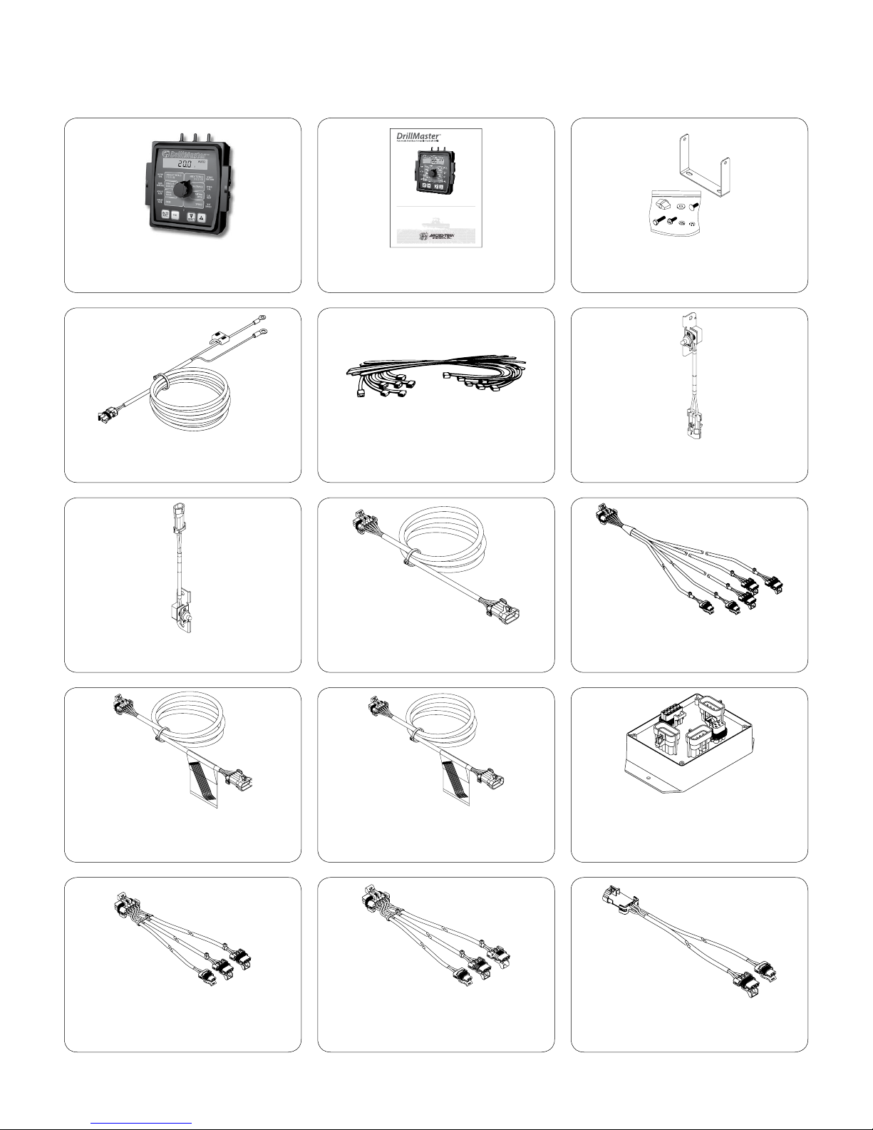
Component Parts and Assembly Hardware
Before beginning installation, check the carton contents for the following items:
DrillMaster Console
P/N 17899
Power Cable
P/N 14315
System Manual
System Manual
P/N 50318
14” Nylon cable ties (10)
P/N 12910
(2)
(2)
(2)
(2)
(2)
(2)
(2)
Console Mount Kit
P/N 13181
Run/Hold Switch
P/N 21778
Power Switch
P/N 21779
15’ Extension Cable
(Single Section)
P/N 13222
DrillMaster Cable
(Multi Sections 1 & 3)
P/N 17881
40’ 10-Pin
Extension Cable
P/N 17096
10’ Extension Cable
(SIngle & Multi Section)
P/N 13221
DrillMaster Cable
(Multi Section 2)
P/N 17882
DrillMaster Cable
(Single Section)
P/N 17894
DrillMaster Module
(Multi Section)
P/N 21612
DrillMaster Cable
(Multi Sect. PWM & R/H)
P/N 17883
5
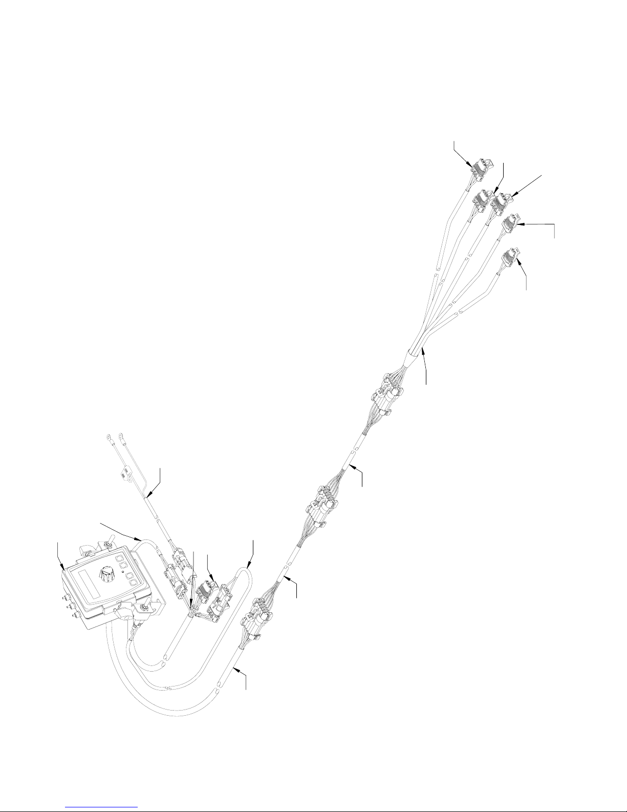
DrillMaster System Layout
Mounted Single Section
BIN LEVEL
SENSOR
REMOTE RUN/
HOLD SENSOR
SECTION 1 SEED
METER SENSOR
PWM CONTROL
VALVE
DRILLMASTER
CONSOLE
SECTION 1
ON/OFF VALVE
P/N 14315
P/N 17894 (10’)
P/N 21779
P/N 21778
YELLOW TIE
SPEED
P/N 13222 (15’)
P/N 13221 (10’)
P/N 21088
6
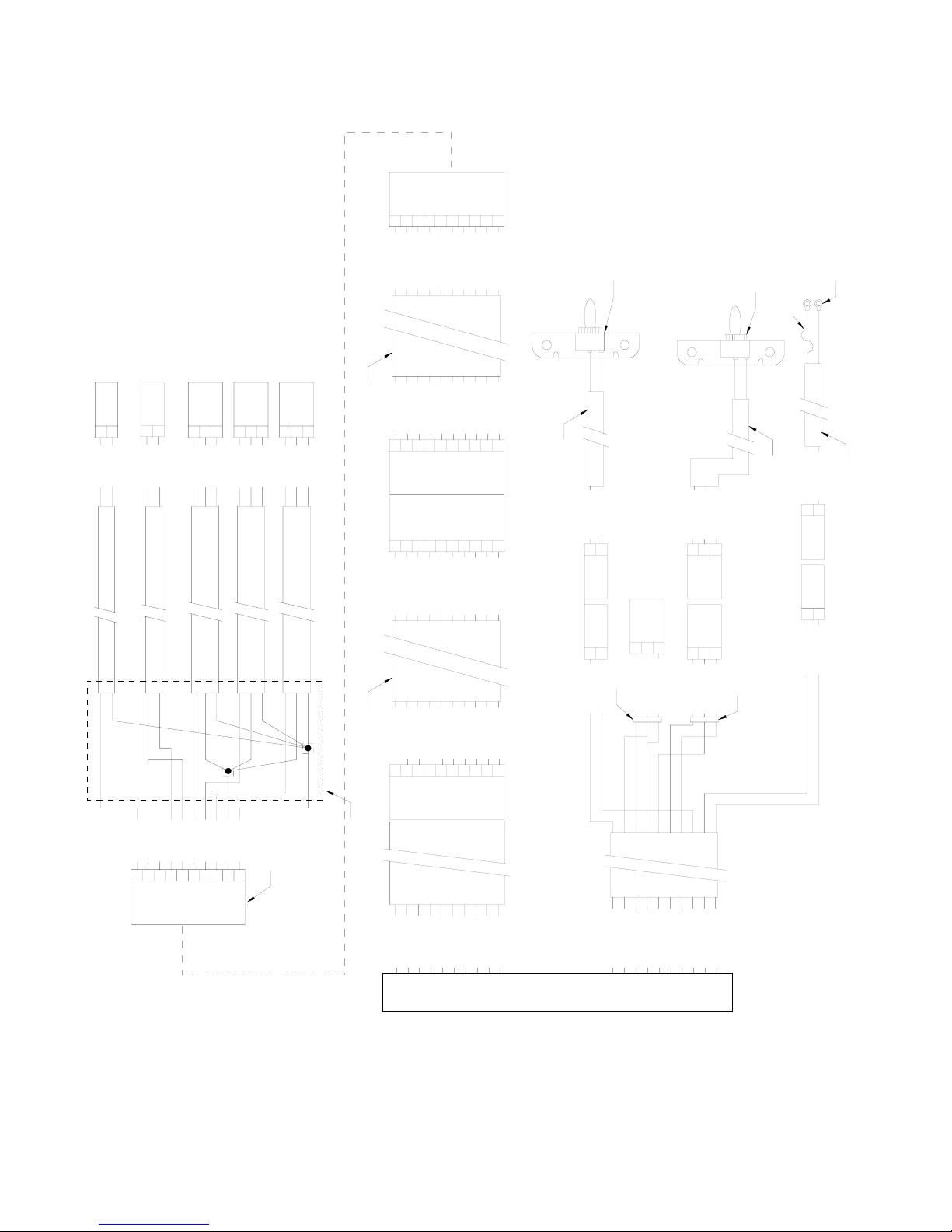
DrillMaster Wiring Diagram
POWER CABLE
TION 1 ON/OFF
TION 2 ON/OFF
TION 2 ON/OFF
RUN/HOLD SIGNA
SPEED GROUND
RUN/HOLD POWE
RUN/HOLD SIGNA
RUN/HOLD GROUND
Mounted Single Section
ABCDEDGHJ
10-PIN
M/P
SHROUD
K
SECTION 1
POPPET VALVE
SECTION 1 ON/OFF
GROUND
TOWER
2-PIN M/P
A
B
18 GA. RED
18 GA. BLK
120 IN.
PWM CONTROL VALVE
PWM -
PWM +
TOWER
2-PIN M/P
A
B
18 GA. BLK
18 GA. RED
120 IN.
SECTION 1 SEED
METER SENSOR
FLOW SIGNAL
+ VES
GROUND
M/P
3-PIN
TOWER
ABC
18 GA. RED
18 GA. WHT
18 GA. BLK
120 IN.
REMOTE RUN/HOLD
SENSOR
BIN LEVEL SENSOR
RUN/HOLD SIGNAL
+ VES
GROUND
BIN NEAR EMPTY SIGNAL
+ VES
GROUND
M/P
TOWER
18 GA. WHT
18 GA. BLK
120 IN.
M/P
3-PIN
ABC
18 GA. RED
18 GA. WHT
120 IN.
TOWER
18 GA. BLK
3-PIN
ABC
18 GA. RED
20 GA. BRN
20 GA. RED
20 GA. ORG
P/N 13221
20 GA. BRN
20 GA. RED
20 GA. ORG
ABCDEDGHJ
ABCDEDGHJ
20 GA. BRN
20 GA. RED
20 GA. ORG
20 GA. YEL
20 GA. GRN
20 GA. YEL
20 GA. GRN
10-PIN
10-PIN
20 GA. YEL
20 GA. GRN
20 GA. BLU
20 GA. VIO
20 GA. BLU
20 GA. VIO
M/P
TOWER
M/P
SHROUD
20 GA. BLU
20 GA. VIO
20 GA. GRY
20 GA. WHT
20 GA. GRY
20 GA. WHT
20 GA. GRY
20 GA. WHT
20 GA. BLK
20 GA. BLK
K
K
20 GA. BLK
P/N 21779
18 GA. RED
18 GA. BLK
A
B
SHROUD
2-PIN M/P
TOWER
2-PIN M/P
A
B
16 GA. BRN
20 GA. GRY
POWER SWITCH
5/16 IN. RING
RUN/HOLD SWITCH
CONN (2 PLCS)
10 A FUSE
FUSE HOLDER
14 GA. ORG
14 GA. BLU
P/N 21778
18 GA. RED
18 GA. BLK
ABC
SPEED
SHROUD
M/P
3-PIN
M/P
3-PIN
ABC
YELLOW TIE
16 GA. ORG
16 GA. RED
TOWER
16 GA. YEL
M/P
3-PIN
TOWER
ABC
20 GA. BLU
20 GA. GRN
20 GA. VIO
GRAY TIE
TOWER
2-PIN W/P
SHROUD
2-PIN W/P
16 GA. WHT
16 GA. BLK
P/N 14315
18 GA. RED
18 GA. RED
18 GA. BLK
18 GA. RED
18 GA. RED
18 GA. RED
18 GA. WHT
18 GA. BLK
ABCDEFGHJ
M/P
10-PIN
TOWER
P/N 17894
K
P/N 13221
HEAT SHRINK
20 GA. BRN
20 GA. RED
20 GA. ORG
20 GA. YEL
20 GA. GRN
20 GA. BLU
20 GA. VIO
20 GA. GRY
ABCDEDGHJ
M/P
10-PIN
TOWER
18 IN.
16 GA. BRN
16 GA. RED
16 GA. ORG
20 GA. YEL
20 GA. GRN
20 GA. BLU
20 GA. VIO
20 GA. GRY
DRILL MASTER CONSOLE
L
FLOW SIGNAL
PWM - SIGNAL
PWM + SIGNAL
SEC
SEC
SEC
BIN NEAR EMPTY SIGNAL
7
20 GA. WHT
20 GA. BLK
K
16 GA. WHT
16 GA. BLK
GROUND
+VES PROTECTED
18 IN.
16 GA. BRN
16 GA. RED
+VES
SPEED POWER
16 GA. ORG
20 GA. YEL
SPEED SIGNAL
20 GA. GRN
20 GA. BLU
20 GA. VIO
20 GA. GRY
L
R
SWITCHED VES
16 GA. WHT
16 GA. BLK
+VES
GROUND

DrillMaster System Layout
Drawn Multi Section
PWM VALVE
RIGHT SECTION
SEED METER
SENSOR
BIN LEVEL SENSOR
ON/OFF VALVE
360”
316”
366”
P/N 17881
P/N 14315
P/N 17883
34”
34”
120”
REMOTE RUN/HOLD
SENSOR
CENTER SECTION
SEED METER SENSOR
BIN LEVEL SENSOR
72”
120”
P/N 17882
ON/OFF VALVE
360”
SEED METER
LEFT SECTION
366”
316”
P/N 21612
SENSOR
ON/OFF VALVE
BIN LEVEL SENSOR
P/N 17881
P/N 17899
P/N 21779
YELLOW TIE
SPEED
P/N 21778
P/N 13221 (10’)
P/N 21088
P/N 17096 (40”)
8

DrillMaster Wiring Diagram
TION 1 ON/OFF
PWM + SIGNAL
RUN/HOLD SIGNA
BIN NEAR EMPT
SPEED GROUND
RUN/HOLD POWER
RUN/HOLD SIGNA
RUN/HOLD GROUND
Drawn Multi Section
FLOW SIGNAL SECTION 3
BIN NEAR EMPTY SIGNAL 3
SECTION 1 ON/OFF
M/P
M/P
3-PIN
3-PIN
TOWER
TOWER
TOWER
2-PIN M/P
ABC
18 GA. RED
ABABC
18 GA. WHT
18 GA. BLK
18 GA. RED
18 GA. WHT
18 GA. BLK
18 GA. RED
18 GA. BLK
K
360 IN.
276 IN.
J
366 IN.
H
18 GA. BLK
G
18 GA. RED
D
18 GA. BLK
E
18 GA. WHT
D
18 GA. RED
C
18 GA. BLK
B
18 GA. WHT
A
18 GA. RED
M/P
TOWER
10-PIN
SHROUD
M/P
10-PIN
K
J
GROUND
H
SECTION 1 ON
G
GROUND
D
+VES
E
D
GROUND
C
+VES
B
A
RUN/HOLD
M/P
3-PIN
TOWER
ABC
18 GA. RED
18 GA. WHT
18 GA. BLK
34 IN.
18 GA. RED
18 GA. WHT
18 GA. BLK
M/P
SHROUD
M/P
TOWER
+VES
GROUND
R/H SIGNAL
FLOW SIGNAL SECTION 2
M/P
3-PIN
ABC
18 GA. RED
18 GA. WHT
120 IN.
18 GA. RED
18 GA. WHT
ABCDEDGHJ
+VES
FLOW SIGNAL SECTION 2
MODULE
DRILLMASTER
MULTI-SECTION
PWM
TOWER
2-PIN M/P
A
B
18 GA. RED
18 GA. BLK
34 IN.
P/N 17883
18 GA. RED
18 GA. BLK
ABCDEABCDEDGHJK
5-PIN
5-PIN
ABCDE
PWM - SIGNAL
PWM + SIGNAL
BIN NEAR EMPTY SIGNAL 1
FLOW SIGNAL SECTION 1
3-PIN
TOWER
ABC
18 GA. BLK
18 GA. RED
18 GA. BLK
18 GA. RED
18 GA. WHT
10-PIN
10-PIN
+VES
GROUND
BIN NEAR EMPTY SIGNAL 2
BIN NEAR EMPTY SIGNAL 2
M/P
18 GA. WHT
34 IN.
18 GA. BLK
M/P
TOWER
M/P
SHROUD
GROUND
SECTION 2 ON/OFF
TOWER
2-PIN M/P
A
18 GA. BLK
18 GA. RED
120 IN.
18 GA. RED
18 GA. BLK
GROUND
SECTION 2 ON
TOWER
B
18 GA. BLK
K
P/N 17882
A
FLOW SIGNAL SECTION 3
B
+VES
C
GROUND
D
BIN NEAR EMPTY SIGNAL 3
E
+VES
F
GROUND
G
SECTION 3 ON
H
GROUND
J
K
10-PIN
M/P
SHROUD
10-PIN
M/P
TOWER
A
B
C
D
E
F
G
H
J
K
18 GA. RED
18 GA. WHT
18 GA. BLK
18 GA. RED
18 GA. WHT
18 GA. BLK
18 GA. RED
18 GA. BLK
3-PIN
ABC
18 GA. RED
FLOW SIGNAL SECTION 1
BIN NEAR EMPTY SIGNAL 1
SECTION 3 ON/OFF
M/P
M/P
3-PIN
TOWER
TOWER
TOWER
2-PIN M/P
A
B
ABC
18 GA. WHT
18 GA. BLK
18 GA. RED
18 GA. WHT
18 GA. BLK
18 GA. RED
18 GA. BLK
360 IN.
276 IN.
366 IN.
P/N 17881
P/N 21612
SECTION 1 ON
SECTION 2 ON
ABCDEDGHJ
ABCDEDGHJ
ABCDEDGHJ
20 GA. BRN
20 GA. RED
P/N 17096
20 GA. BRN
20 GA. RED
ABCDEDGHJ
ABCDEDGHJ
20 GA. BRN
20 GA. RED
P/N 13221
20 GA. BRN
20 GA. RED
ABCDEDGHJ
ABCDEDGHJ
20 GA. BRN
20 GA. RED
SECTION 3 ON
PWM + SIGNAL
PWM - SIGNAL
FLOW
M/P
10-PIN
TOWER
M/P
10-PIN
SHROUD
20 GA. ORG
20 GA. YEL
20 GA. GRN
20 GA. BLU
20 GA. ORG
20 GA. YEL
20 GA. GRN
20 GA. BLU
M/P
10-PIN
TOWER
M/P
10-PIN
SHROUD
20 GA. ORG
20 GA. YEL
20 GA. GRN
20 GA. BLU
20 GA. ORG
20 GA. YEL
20 GA. GRN
20 GA. BLU
M/P
10-PIN
TOWER
M/P
10-PIN
SHROUD
20 GA. ORG
20 GA. YEL
20 GA. GRN
20 GA. BLU
R/H SIGNAL
BIN NEAR EMP
+VES
GROUND
K
K
K
20 GA. VIO
20 GA. GRY
20 GA. WHT
20 GA. BLK
20 GA. VIO
20 GA. GRY
20 GA. WHT
20 GA. BLK
K
K
20 GA. VIO
20 GA. GRY
20 GA. WHT
20 GA. BLK
20 GA. VIO
20 GA. GRY
20 GA. WHT
20 GA. BLK
K
K
20 GA. VIO
20 GA. GRY
20 GA. WHT
20 GA. BLK
P/N 21779
18 GA. RED
A
2-PIN M/P
2-PIN M/P
A
16 GA. BRN
POWER SWITCH
18 GA. BLK
B
SHROUD
TOWER
B
YELLOW TIE
20 GA. GRY
3-PIN
ABC
16 GA. ORG
SPEED
M/P
16 GA. RED
P/N 17881
5/16 IN. RING
FUSE HOLDER
P/N 21778
10 A FUSE
14 GA. ORG
14 GA. BLU
TOWER
2-PIN W/P
SHROUD
2-PIN W/P
16 GA. WHT
16 GA. BLK
CONN (2 PLCS)
P/N 14315
POWER CABLE
RUN/HOLD SWITCH
18 GA. RED
18 GA. BLK
ABC
M/P
3-PIN
SHROUD
M/P
TOWER
3-PIN
TOWER
ABC
GRAY TIE
16 GA. YEL
20 GA. BLU
20 GA. GRN
20 GA. VIO
16 GA. BRN
SEC
18 IN.
16 GA. RED
16 GA. ORG
20 GA. YEL
20 GA. GRN
20 GA. BLU
FLOW SIGNAL
PWM - SIGNAL
SECTION 2 ON/OFF
SECTION 2 ON/OFF
9
20 GA. VIO
20 GA. GRY
L
Y SIGNAL
P/N 21088
16 GA. WHT
16 GA. BLK
GROUND
+VES PROTECTED
18 IN.
16 GA. BRN
16 GA. RED
16 GA. ORG
20 GA. YEL
DRILLMASTER CONSOLE
+VES
SPEED POWER
SPEED SIGNAL
20 GA. GRN
20 GA. BLU
20 GA. VIO
20 GA. GRY
16 GA. WHT
16 GA. BLK
L
+VES
GROUND
SWITCHED VES

PRESSURE
RIGHT FLOW SENSOR
CHECK VALVE
FLOW SENSOR
CHECK VALVE
DrillMaster Seed Rate Controllers
Single Drive Closed Center Single Drive Open Center
RETURN
PWM VALVE
POPPETVALVE
Multi-Drive Closed Center
FLOW SENSOR
POPPET VALVE
RETURN
PWM VALVE
PRESSURE
RETURN
PRESSURE
LEFT POPET VALVE
CENTER POPPET VALVE
PWM VALVE
LEFT FLOW SENSOR
RIGHT POPET VALVE
CENTER FLOW SENSOR
CENTER POPPET VALVE
RETURN
PRESSURE
CENTER FLOW SENSOR
RIGHT FLOW SENSOR
RIGHT POPPET VALVE
PWM VALVE
LEFT FLOW SENSOR
LEFT POPPET VALVE
Multi-Drive Open Center
10
Installation
side or dashboard mounting
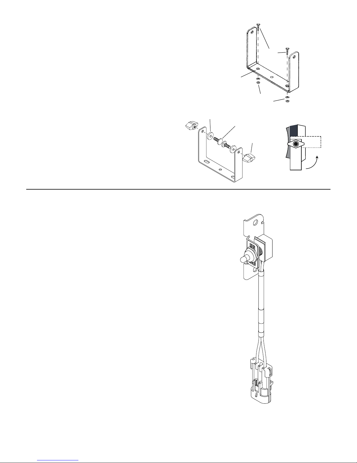
Mounting the Display Console
Illustration 1A
Select a mounting location which seems most workable,
and that best fits your needs. It should be con ve nient to
reach and high ly vis i ble to the op er a tor. DO NOT IN STALL
IN A POSITION THAT OB STRUCTS THE VIEW OF THE ROAD
OR WORK AREA. Whenever pos si ble, avoid lo ca tions that
ex pose the con sole to direct sun light, high tem per a ture,
strong chem i cals or rain.
Place the mounting bracket in selected lo ca tion, mark holes,
drill 1/4” (7mm) holes and mount bracket with bolts, lockwash ers and nuts pro vid ed. (Use self-tap ping screws if not
prac ti cal to use bolts.) See Illustration 1A.
Put rubber washers on carriage bolts and put the bolts
through the bracket holes from the inside out. Loosely
attach the mount knobs onto the bolts. Place console over
carriage bolt heads and tighten knobs to se cure the console.
See Il lus tra tion 1B.
Illustration 1B
Drill ¼” (7mm)
holes for bolts,
or 3/16“ (5mm)
holes for selftapping screws.
Rubber washer
Installing Run/Hold and Power Control Switches
Install the Run/Hold switch assembly into the bracket
using the steps below:
1. Remove the mount knob from right side of the console.
2. Install the bracket over the carriage bolt and along side
the console bracket.
3. Install the mount knob on the carriage bolt and tighten
to secure the console and run/hold switch bracket in
place.
4. Mate the switch harness connector into the
corresponding connector (gray tie) on the console
harness.
Lockwashers
and nuts
Carriage bolts
Mount knob
Bolts
CONSOLE END VIEW
Console easily adjusts for
.
NOTE: Install Power Switch on the left side of console,
same general steps as described above. Then, connect
the Power Switch cable connector (2 pin) to the mating
connector on the console harness.
Console Run/Hold Switch PN 21778
Illustration 2
11

Installation (cont)
Electrical Installation
This section explains how to connect your DrillMaster to a
12-volt power source, and how to connect your oil bypass
valves or dump valves.
NOTE: The DrillMaster must be connected to a 12-volt DC
negative ground electrical system.
POWER/BATTERY CONNECTION
Locate the power cable for the DrillMaster and route to the
battery. When routing cable to con sole, avoid ar eas where
the ca ble may be sub ject ed to abra sion or exces sive heat.
At tach the BLUE wire (ground) to a screw or bolt on the
equipment frame. See Il lus tra tion 3. Be sure there is a good
metal-to-metal con tact. Connect the ORANGE wire to the
positive battery terminal.
Connect the power to the DrillMaster console by plugging
the 2-pin W/P tower on the power cable into the 2-pin W/P
shroud of the display console.
Speed Sensor Options
In addition to the standard Hall-effect magnetic speed
sensor, the DrillMaster may be interfaced with a va ri ety of
other speed sensing equipment. Several options are listed
below.
Illustration 3
+12 VDC
(Orange)
10 - Amp in-line
fuse required
(+)
Ground
(Blue)
Astro 5 or other GPS Speed Sensor Interface
The DrillMaster may also be used with most GPS speed
sensors that output a pulsed signal, such as the Micro-Trak
Astro 5, SkyTrak or Dickey-John GPS speed sensors. An
adapter cable may be required.
VanscoTM Radar Speed Sensor
The Vansco radar speed sensor uses a microwave (radar)
signal to deliver a reliable, accurate speed signal for electronic
equipment. It features state-of-the-art electronic design/
manufacturing, rugged aluminum housing and complete
testing and certification.
Radar Interface
The DrillMaster may also be interfaced with most popular
radar ground speed sensors. An adapter cable is re quired for
proper interface.
SEE APPENDIX E FOR LIST OF ADAPTER CABLES FOR RADAR.
Contact a Micro-Trak sales representative for de tails on any of these products,
or call Mi cro-Trak Systems, Inc. at 1-800-328-9613.
Astro 5 GPS Speed Sensor
Vansco Radar Speed Sensor
12

Installation (cont)
Remote Run/Hold
NOTE: An optional remote run/hold sensor can be used in
place of the provided Run/Hold switch.
The run/hold sensor cable has a BLACK body and mates
with the main har ness ca ble having a GRAY cable tie near
the 3-pin M/P con nec tor. Make certain that you install the
correct sen sor cable and connect it to the correct connector
on the main harness.
IMPORTANT
• The basic idea is to attach a magnet to a lever or some
part of the equipment that moves when the im ple ment
is raised and lowered. The Hall-effect Run/Hold sensor is
sensitive ONLY to the south pole of the magnet. Install
the magnet with the dashed line facing the sensor.
When the mag net is near the sen sor, the con sole will be
in HOLD and the area and distance counting functions
will be disabled.
Hydraulic Cylinder Mounting
Remote Run sensor on hydraulic cylinder. Magnet and sensor are in line
when equipment is lowered and operating.
Illustration 4
Magnet
Hold
Position
Sensor
(Black body)
Run
Position
North
South
DrillMaster Care and Maintenance
Store the console in a cool dry location if it will not be used for an extended period of time, such as
during the off-season. As with any electronic equipment, use care in cleaning so that water or other
liquids do not enter the case.
13

DrillMaster Console Func tions
The DrillMaster features a large, easy-to-read liquid crystal display, easy-to-use rotary dial and lighted panel for night use.
SECTION ON/OFF: The Console has three Section ON/OFF toggle switches on top of the Console. The toggle switches turn
Drill Sections on and off directly and also signal the Console which Sections are on or off.
WEIGHT TOTALS 1 2 3 : Displays total product lbs.
(kg) applied. Tons (metric tons) on rollover.
May be reset. (NOTE: WEIGHT and
AREA counters work in pairs, if
WEIGHT counter 1 is reset, it also
resets AREA counter 1).
WEIGHT/MINUTE: Displays lbs.
(kg) of product dispensed per
minute.
AREA/HOUR: Displays
calculated Acres/Hour (Eng),
Hectares/Hour (Metric) or kFt2/
Hour (Turf).
RATE: Displays application
rate in lbs. /acre, kg/hectares
or lbs./kFt2.
AREA TOTALS 1 2 3: Keeps a running count of the
total acres, hectares or kFt2 worked. May be
reset. (NOTE: WEIGHT and AREA
counters work in pairs, if AREA
counter 1 is reset, it also resets
WEIGHT counter 1).
DISTANCE: Displays distance
traveled in feet (meters). May
be reset.
METER RPM: Displays Seed
Drive shaft RPM.
SPEED: Displays ground
speed in miles per hour
(kilometers per hour).
WARNING LIGHT: Indicates
over or under application of
10% of the Target Rate in
AUTO or Loss of Sensor Signal
in MAN. Also lit when in CAL.
METER CAL: Used in calibration mode to enter the Meter Cal
in Pulses/Lbs/Row (English/Turf) or Pulses/Kg/Row (Metric).
ROW SPACING: Used in the calibration mode to enter the
Row Spacing in inches (cm).
ADJUST RATE: Used in calibration mode to enter an
amount of change for on-the-go adjustments to the
target rate lbs/acre (kg/hectares).
TARGET RATE: Used in calibration mode to enter the target
application rate Lbs/Acre (Eng). Kg/Hectares (Metric) or Lbs/
KFt2 (Turf).
Soft Key Functions
RESET
PROGRAM KEYS:
Used to increment and decrement the different calibration values.
• RESET when not in CAL, clears the selected counter when held for two sec onds.
• When in CAL, the “+” key increases and the “-” decreases the value displayed.
Adjusts Target Rate in AUTO or Application Rate in MAN.
AUTO
MAN
CAL
Key which changes
operation from automatic
control to manual valve
control.
This key is used to enter &
exit the calibration mode.
Calibration PositionsCalibration Positions
ROWS SECTION: Used in calibration mode to enter the Rows
per Section from 0 to 255 rows for the Section selected.
SPEED CAL: Used in calibration mode to enter the speed
calibration number in inches (cm) per pulse edge.
CAL TEST: Not a true “Calibrate Factor” but rather a method
of testing the Drill to determine if the correct Meter Cal factor
is being used and to test if each Row is dispensing the correct
amount of seed.
TEST SPEED: Not a true “Calibrate Factor” but rather a
method of testing the Drill. Typically it is used to confirm
that Auto Control can be maintained across a range of
expected ground Speeds.
14
Calibration
Selecting Measurement Units
English, Metric or Turf?
The DrillMaster is capable of displaying in for ma tion in Amer i can
En glish or standard Metric measurement. The DrillMaster is
shipped from the factory programmed for English.
NOTE: The following procedures will also load factory
default calibration values. To simply change units without
loading defaults, see the “Special Calibration” section.
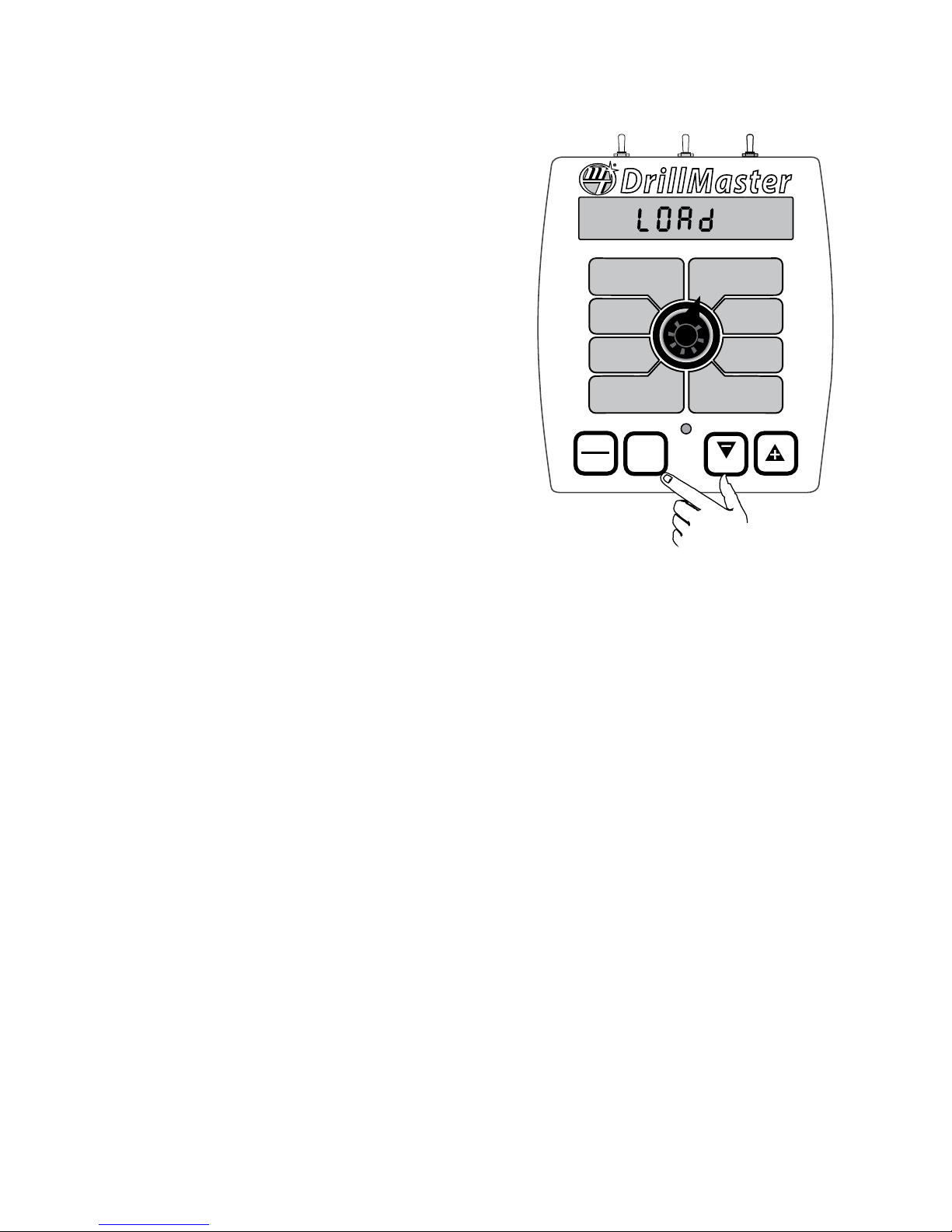
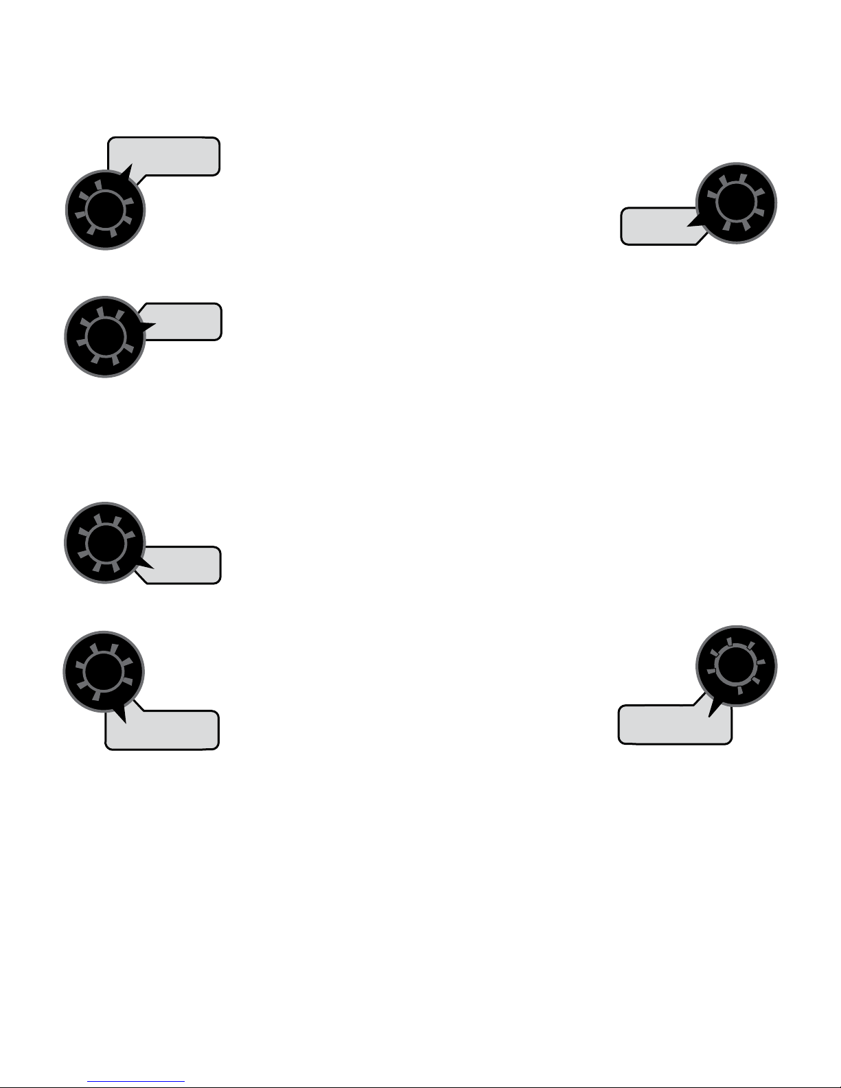
METRIC
• You must be in HOLD or have all Sections OFF to enter
Cal. To activate the Metric mode, turn power OFF and
place the ro ta ry switch at “AREA TOTALS.” Hold down
both the “CAL” and “-” keys and turn power ON. See
Il lus tra tion 5. The con sole will display LOAd for two
seconds. Once LOAd is displayed, release the two keys.
To “lock-in” Metric mode you must enter and exit cali bra tion. Press and hold the CAL key until “CAL” icon
appears on the display. The con sole is now in cal i bration and Metric mode is selected. Exit CAL by pressing
and holding the “CAL” key until CAL disappears from the
display (ap prox i mate ly 1 second).
NOTE: You MUST exit CAL to lock in Metric units.
ENGLISH
• You must be in HOLD or have all booms OFF to enter Cal.
To activate the English mode, turn power OFF and place
the ro ta ry switch in the WEIGHT TOTALS position. Hold
down both the “CAL” and “-” keys and turn power ON.
The con sole will display LOAd. Once LOAd is displayed,
release the two keys. To “lock-in” English mode you
must enter and exit cal i bra tion. Press and hold the CAL
key until “CAL” lights on the display. The console is now
in cal i bra tion and English mode is selected.
METER
CAL
ROW
SPACING
ADJUST
RATE
TARGET
RATE
DrillMaster
WEIGHT TOTALS
(1) (2) (3)
WEIGHT /
MINUTE
AREA/
HOUR
RATE
AUTO
MAN
CAL
AREA TOTALS
RESET
(1) (2) (3)
DISTANCE
METER
RPM
SPEED
Illustration 5
ROWS/
SECTION
SPEED
CAL
CAL
TEST
TEST
SPEED
NOTE: You MUST exit CAL to lock in English units.
Exit CAL by pressing and holding the “CAL” key until CAL
disappears from the display (approximately 1 second).
TURF
• Selected only in “Special” Calibration. See Page 23.
NOTE: In metric, the width will have a decimal point, in
English there is no decimal point. Also, changing from En glish
to Met ric mode may change or alter any previously en tered
cal i bra tion values. After switch ing mea sure ment modes, confirm that all cal i bra tion val ues are correct.
15
Calibration (cont)
Entering Calibration Values
To enter or change any of the system’s calibration values,
turn all used Sections OFF or put the console in HOLD and
press and hold the CAL button until the “CAL” icon appears
(approximately one second).
NOTE: Calibration may be entered while moving, but
it is not rec om mend ed, for safety reasons, to attempt
calibration while the vehicle is mov ing.
The console will remain in calibration mode, with the RED
warning light illuminated until you exit calibration or turn
power OFF.
NOTE: The Console must be in Hold or all used Sections
OFF in order to toggle Calibrate Mode on, however, it can
be in Run, Hold or Sections ON or OFF to toggle Calibrate
Mode off.
Once in calibration mode, you may change any one, all, or
none of the values, in any order.* To select a calibration
position, simply turn the rotary selector to the desired
po si tion. Calibration positions are identified by the White
labeling on each side of the rotary selector. All values are
entered and adjusted using the “+” and “-” but tons on the
front panel.
Test speed must be last.
*
Hold the “CAL key again for 1 second to exit calibration.
“CAL” will disappear from the display.
NOTE: You MUST exit CAL to save changes.
ROWS/SECTION: This displays the Rows Per Section from
0 to 255 rows for the Section selected. Unused Sections must
AREA TOTALS
(1) (2) (3)
up to three Sections. The total width of
the Drill (sum of all Section widths) must
not exceed 65,535 inches or 65.535 meters
(Number Rows X Row Spacing).
ROWS/
SECTION
To adjust the number of Rows of a
particular Section simply turn that Section on and
all others Off. The corresponding Section Icon
1 - 3 will turn on and the number of rows in that
section can be adjusted. Actually the first Section
turned on, from left to right, will be selected.
For example if Section 1 is off and Sections 2
and 3 are on, then Section 2 is selected since
it is the “first” Section on, and Section 2 Rows
can be adjusted. If no Sections are turned on, it
will display “no SECtn” (alternating “no” and
“Section”) to remind the user to turn a Section on,
and/or select RUN to enable the Sections.
be programmed
to zero rows. The
DrillMaster can have
SPEED CAL: This position is used to calibrate the speed
sensor for ac cu rate speed and dis tance measurement. When
this position is selected,
DISTANCE
is the number shown along with “CAL” on
the display. See details for determining
SPEED CAL on page 17.
SPEED
CAL
the display will show
the SPEED CAL value.
The SPEED CAL value
CAL TEST: This is not a true “Calibrate Factor” but rather
a method of testing the Drill to determine if the correct
Meter Cal factor is being used and to test if a particular Row
is dispensing the correct amount of seed.
When RUN is selected it will use Test Speed
and AUTO control to dispense Sample Size
METER
RPM
The “Cal Test” is recommended for a quick spot check to
ensure proper operation. It can be used to:
• Test the accuracy of ‘Meter Cal’ (make sure it matches
what the Drill is actually planting).
• Test one Row, or many Rows, or the entire Drill at once.
• Test the consistency of the Rows (see variation from one
row to another).
• Find the minimum and maximum Row (lowest and
highest planting rate).
• Find the AVERAGE planting rate for the entire Drill.
This procedure is different than the “Fine Tuning” found in
the Meter Cal section in the following ways:
1. This procedure is a quick method to test the accuracy
of Meter Cal. It DOES NOT require weighing entire Drill.
Instead only a small sample from one Row is needed
and it can be performed in the field. But it can also test
multiple Rows at once if desired.
2. This procedure uses AUTO to make sure the planter is
running at the Target Speed. This is important because
the Seed Meter planting mechanism is speed sensitive
so it must be tested at the proper speed. In the Meter
Cal Fine Tuning procedure, the user can use AUTO
or MANUAL mode and use a lower or higher speed if
desired.
3. This procedure uses a fixed Sample Size (another cal
factor) making it more repeatable. In the Meter Cal Fine
Tuning procedure the sample size is up to the operator
and can be any size.
4. This procedure automatically stops when the sample
size is reached. In the Meter Cal Fine Tuning procedure
the operator must stop the test at the appropriate time.
5. This procedure will not affect or change any of the three
Weight Totals counters. In the Meter Cal Fine Tuning
procedure one of the three Weight Totals counters must
be cleared.
NOTE: See the Cal Test Fine Tuning procedure in Appendix C.
amount of Seed per row
CAL
and then automatically
TEST
stop.
16
Calibration (cont)
Entering Calibration Values (cont)
TEST SPEED: Test Speed is not a true “calibrate factor” but
rather a method of testing the Drill. Typically it is used to conrm that Auto Control can be maintained across a range of
expected ground Speeds. In addition, the Test Speed is used
in “Cal Test” mode.
Each time Calibration is selected the Test
Speed will be reset to 0 mph (turned o) so it
does not interfere with any other calibration
procedures. If the opera-
SPEED
TEST
SPEED
adjust it above zero mph. Any non-zero Test Speed will make
the CAL icon ash to remind the operator that a “Test Speed”
is running and Calibration is no longer fully operating. He
can no longer change any Calibrate factors. Instead, the normal operating modes are enabled except they will all use the
Test Speed instead of the actual speed input. The WARN LED
will remain on, as reminder that Test Speed is selected. Hold
will operate normally and Speed will operate using the Test
Speed and Weight, Area/Hour, Rate, and Weight/Minute will
also operate. The Area and Distance will not change while in
the Test Speed Mode.
If AUTO is selected the Console will try to run the PWM Valve
to reach the Target Rate (lbs/Acre). The “+”/”-” keys can be
used as normal to change the Target Rate in steps equal to
the “Adjust Rate”.
To exit “Test Speed” the user must hold the CAL key for 1 sec-
ond (or turn the Console o) and the CAL icon will stop ashing, the WARN LED will turn o and it will exit Test Speed and
CAL Mode. The Test Speed cannot be turned o by reducing it
to zero because the minimum Test Speed is 0.1 mph.
tor wants to use a Test
Speed he must select
the Speed position and
then use the “+” key to
TARGET RATE: Enter the value for the
desired or Target Rate in Lbs/Acre (English)
or Lbs/ kFt2 (Turf ) or kg/hectare (Metric) with
one or more decimal places as follows. It can
range from 0.00 to 99,999. This is the
application rate that
the console will lock
TARGET
RATE
RATE
onto when operating
in AUTO.
ADJUST RATE: Enter the value for the desired amount
of change in lbs. per acre, kg per hectare or
lbs./ kFt2 to be used for making on-the-go
rate adjustments when operating in AUTO.
For example, if a value
“1.0” is entered, you
will be able to increase
ADJUST
RATE
AREA/
HOUR
or decrease your
application rate in one-lb. (kg) increments during operation
in AUTO. To disable this feature, simply enter “.0” for a val ue.
ROW SPACING: Adjusts Row Setting value to the nearest
tenth of an inch (tenth
of a centimeter).
ROW
SPACING
WEIGHT /
MINUTE
METER CAL: Adjusts Meter Cal value from 1 to 65,535 Pulses/
Lbs/Row (English,
Turf) or Pulse/Kg/
Row (Metric). NOTE:
METER
CAL
WEIGHT TOTALS
(1) (2) (3)
See Appendix D for
additional information.
Factory-Loaded Calibration Values
Calibration Factor
TARGET RATE 60.0 lbs/acre 70.0 kg/hectare
ADJUST RATE 1.0 lbs/acre 1.0 kg/hectare
ROW SPACING 10.0 inches 25.4 centimeters
SPEED CAL 0.189 in/edge .48 cm/edge
METER CAL 2767 Pulses/Lbs/Row 6104 Pulses/Kg/Row
Distance 0 0
Area 1, 2, 3 0 0
Volume 1, 2, 3 0 0
ROWS/SECTION 1, 2, 3 12 12
Default Values
English Metric
17
METER
CAL
ROW
SPACING
ADJUST
RATE
TARGET
RATE
DrillMaster
WEIGHT TOTALS
(1) (2) (3)
WEIGHT /
MINUTE
AREA/
HOUR
RATE
AUTO
MAN
CAL
AREA TOTALS
RESET
CALHOLD
(1) (2) (3)
DISTANCE
METER
RPM
SPEED
ROWS/
SECTION
SPEED
CAL
CAL
TEST
TEST
SPEED

Calibration (cont)
Speed Cal for Radar or GPS Speed Sensors
See the table below for SPEED CAL numbers to enter for
various radar models or GPS speed sensors. To fine tune the
SPEED CAL number, see Appendix B.
Radar or GPS Speed Sensor Calibration
Radars
Vansco .150 .38 58.90
Raven .148 .38 59.80
Magnavox .154 .39 57.40
Dickey-john
(NOTE: Dickey-john
radars may be factory
calibrated for any of
these four settings).
English
Cal #
.149 .38 58.94
.199 .51 44.21
.319 .81 27.64
.518 1.32 17.034
GPS Speed
Astro 5 .189 .48 46.56
SkyTrak (Std) .150 .38 58.94
SkyTrak (MT) .910 2.31 9.82
Dickey-john .210 .53 42.00
John Deere
(In-cab speed signal) .197 .50 44.70
Metric
Cal #
Hz/MPH
18

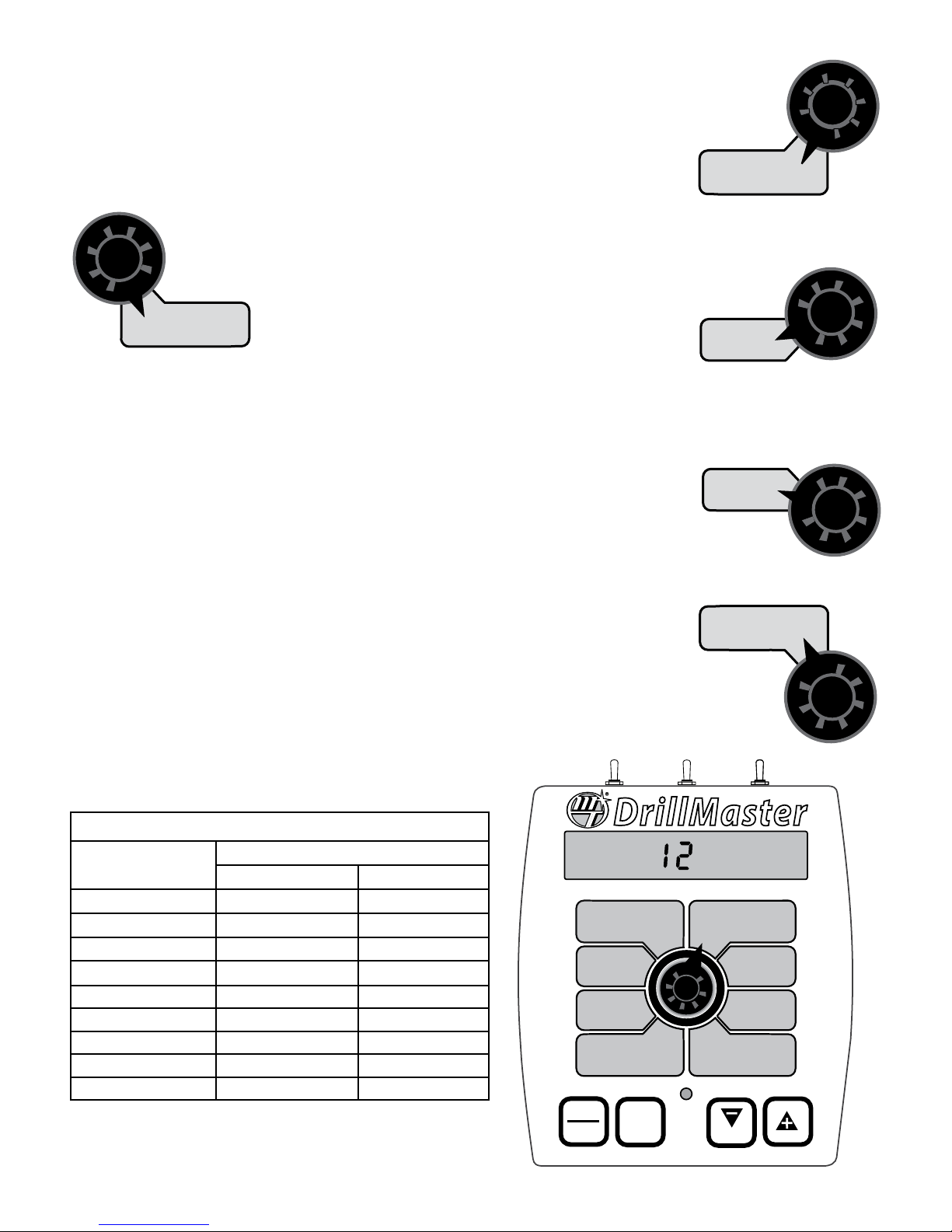
“Special” Calibration
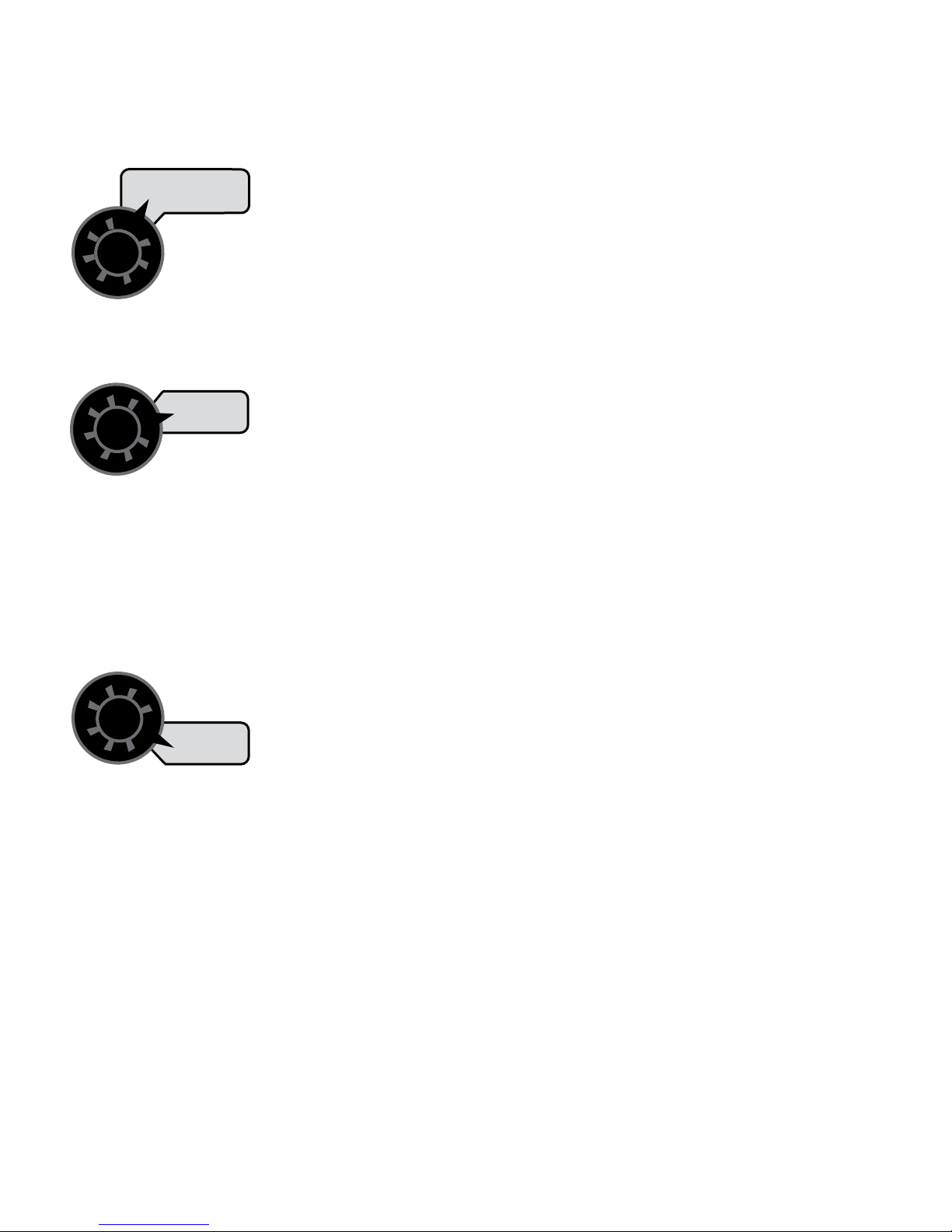
Entering “Special” Calibration
“Special” Calibration is used to set up system parameters
that rarely need to be changed or adjusted. To enter Special
Cal, put the system in HOLD, turn the console OFF, press
and hold both the AUTO/MAN button and CAL button while
turning console ON. The console will display SPEC for 2
seconds to show that the console is in “Special” Calibration.
Release the AUTO/MAN and CAL buttons. The CAL icon and
Warn LED will turn on. The number 1 will also appear in the
lower right display area to indicate that page 1 of Special
Cal is selected. To select page 2 of Special Cal, momentarily
Special Cal
DrillMaster
CALHOLD
Page 1
Auto Shutoff On/Off
Auto Delay Time
METER
CAL
ROW
SPACING
ADJUST
RATE
TARGET
RATE
WEIGHT TOTALS
(1) (2) (3)
WEIGHT /
MINUTE
AREA/
HOUR
RATE
1
AREA TOTALS
(1) (2) (3)
DISTANCE
METER
RPM
SPEED
ROWS/
SECTION
SPEED
CAL
CAL
TEST
TEST
SPEED
press the CAL button and the number 2 will appear in the
lower right display area. To go back to page 1, momentarily
press the CAL button again. The desired “Special” Calibration
parameter(s) can then be accessed with the rotary switch.
See Illustration below.
To exit “Special” Calibration, press and hold the CAL button
for 2 seconds. The console will store any changes and revert
to normal operation.
NOTE: You must exit “Special” Calibration to save changes.
Special Cal
Page 1
Units
Sample Size
Control Speed
PWM Version
Page 2
PWM Frequency
Max PWM
Min PWM
Shaft CAL
AUTO
CAL
MAN
RESET
The following table describes the “Special” Cal parameters
and shows the factory settings. More detailed descriptions
follow the table.
Factory-Loaded “Special” Calibration Values
“Special” Calibration
Parameter
Units
Sample Size 1.00 Lbs 0.50 Kg
Control Speed -1 -1
Shaft Cal 60 60
Auto Shuto On On
Auto Delay Time 1 Sec 1 Sec
PWM Frequency 100 Hz 100 Hz
Max. PWM 90% 90%
Min PWM 30% 30%
Default Factory Setting
English Metric
0 (EnG) (English) 1 (nnEt) (Metric)
19
“Special” Calibration (cont)
Entering Page 1 “Special” Calibration Values
UNITS: Chooses the system of units desired. Turf units are
the same as English
AREA TOTALS
(1) (2) (3)
ROWS/
SECTION
units except Area is in
thousands of square
feet. Use the “+” and
“-” buttons to choose between EnG (American
English Units), MEt (Metric) and TurF (Turf
units). NOTE: Always Check ALL Calibration
Factors after changing UNITS.
SAMPLE SIZE: Sample Size can be adjusted from 0.00 to
655.35 lbs or kg. This
DISTANCE
SPEED
will determine how
much seed is dispensed
CAL
per Row during the Cal
Test. The default is 1.00
pound (0.50 Kg) but it can be adjusted for
various Seed types.
When the Sample Size is set to 0.00 it will stop the “Cal Test”
as soon as it is started. This effectively disables it so the user
can not accidently run the “Cal Test”.
CONTROL SPEED: Control Speed can be adjusted from
-4 to 3. It is normally set in the middle (-1) but if needed, it
allows the user to either decrease or increase
the Control Speed for his particular system.
METER
RPM
CAL
TEST
AUTO SHUTOFF ON/OFF: Area/Hour allows the user to
turn the Auto Shut O feature On or O by using the “+”/”-”
(RESET) keys and the display will show On or Off.
ON OPERATION
While in AUTO mode, when the “Auto Shut
O” feature is turned
on (typical), it will automatically turn the
ADJUST
RATE
AREA/
HOUR
PWM Valve o when HOLD is selected, or when all used Sections are turned o, or when Speed goes to zero. Zero speed
has the same eect as turning all Sections o because of the
“Automatic Section O” feature (Sections automatically turn
o when speed goes to zero). This is useful in most systems
where HOLD must stop hydraulic ow to a drive shaft. The
“Auto Shut O” feature also operates while in Test Speed
mode, it just skips the test for zero speed since Test Speed
can’t be set to zero.
OFF OPERATION
While in AUTO mode, when the “Auto Shut O” feature is
turned o, it will stop automatic control and simply “maintain”
the PWM Valve at the current ow when HOLD is selected, or
when all used Sections are turned o, or when Speed goes
to zero.
NOTE: In the MANUAL mode, selecting Hold, or turning all
used Sections o, will override the Auto Shut feature and
always stop the PWM output independent of Auto Shut O
setting.
SHAFT CAL: Allows the user to enter the Shaft Cal in Pulses
Per Revolution. It can be changed from 1 to 255
(pulse/rev) using the “+”/”–” (RESET) keys. It
should be set to the number of pulses from the
Seed Meter Sensor that result in one revolution
of the Seed meter Shaft.
SPEED
TEST
SPEED
AUTO DELAY TIME: Allows the user to change the Auto
Delay Time. Pressing “+” and “-” buttons will adjust the Delay
Time from 0 (O) to 1, 2, 3, or 4 seconds.
Automatic control is delayed for “Delay Time”
seconds when going from Hold to Run or from
all used Sections o to one or more Sections
on. This provides
time for motorized
valves to operate and
allows the ow to stabilize.
TARGET
RATE
RATE
20
“Special” Calibration (cont)
SPEED
Entering Page 2 “Special” Calibration Values
PWM FREQUENCY: It can be adjusted from 50 Hz to 500
Hz in 1.0 Hz steps. It should be set to the optimum frequency
AREA TOTALS
(1) (2) (3)
ROWS/
SECTION
MAX PWM: It can be adjusted from 0% to 100% in 1%
steps. The PWM duty cycle will remain below this limit in
both manual and auto operation, when in Run. For proper
DISTANCE
maximum PWM function can be used to
ensure the hydraulic flow never exceeds a
maximum amount. This could be used to make sure a drive
shaft never exceeds a maximum RPM, etc. It can also be
used to optimize operation with a particular PWM valve. For
example, if a valve is at max flow when the duty cycle is at
85%, then the max PWM should be set to 85%.
for the particular valve
being used.
operation, it should be
set to some value greater
CAL
than the Minimum
PWM duty cycle. The
MIN PWM: It can be adjusted from 0 to 100% in 1%
steps. The PWM duty cycle will remain above this limit in
both Manual and Auto operation, when in Run. For proper
operation, it must be set to some value less
that the maximum PWM duty cycle.
The minimum PWM
METER
RPM
METER
CAL TEST
a set amount. This could be used to make sure a drive shaft
never stops turning, etc. It can also be used to optimize
operation with a particular PWM valve. For example, if a
valve is set at minimum flow when the duty cycle is 35%,
then Min PWM should be set to 35%.
function can be used
to ensure the hydraulic
flow never drops below
21

Operation
Illustration 6
Console Switches and Buttons
Make sure your system is properly calibrated before beginning
to apply product. We also recommend completion of
Pre-Field System Checkout described on page 27 prior to
beginning any field operations.
CONSOLE POWER/SYSTEM ON/OFF
The system can be turned ON and OFF by using the ON/OFF
switch and bracket kit. When the console is turned on, it will
display the number of hours of operation for 1.5 seconds,
then it will display PULSE for 1.5 seconds and then displays
the Software Number and Software Revision for 1.5 seconds.
The Sections will be disabled (turned off) and the PWM
output will remain off.
DISPLAY
During normal operation, the console will display information
selected by the rotary switch position. Typically the rotary
switch will be set on RATE, as shown in Illustration 6 to
the right. With RATE selected, the console will display the
Application Rate in units in lbs/acre, kg/hectares or lbs./
kFt2. See Rotary Positions on the next page for additional
information about data displayed.
RUN/HOLD SWITCH
The RUN/HOLD is the master switch for turning all (active)
sections on and off.
NOTE: The DrillMaster system can be operated in either
Manual (MAN) or Automatic (AUTO) mode. The following
contains additional information.
AUTO/MAN BUTTON
This button will switch the control status of the system from
fully automatic to manual control. Each press of the button
will change the status. The display will show the AUTO icon
when automatic control mode is active and the MAN icon
when manual control mode is active. NOTE: IF IN “AUTO”
MODE AND NO SPEED SIGNAL IS PRESENT, SYSTEM WILL
SHUT OFF THE BOOMS AUTOMATICALLY.
MANUAL
In MAN , Select RATE then the PWM can be adjusted using
the “+” and “-” (Reset) buttons from Min PWM to Max PWM
in 0.1% steps. The longer the “+” and “-” (Reset) key is
pressed the faster the PWM is changed.
AUTOMATIC
To turn on the AUTO mode, press AUTO/MAN button so
the AUTO icon appears in upper right portion of display.
See Illustration 10. In automatic mode, the system will
control the flow rate to maintain the calibrated application
rate when the vehicle speed changes, or when sections are
turned on or off. To operate the system in automatic mode,
simply turn on the hydraulic system, turn on the desired
number of sections, place the RUN/HOLD switch in the RUN
position and drive.
NOTE: In AUTO mode, the system will not turn the sections
or conveyors on until it has a speed signal. Use either the
RUN/HOLD switch to turn the system off and on when
turning around or to stop spreading at any time. See the
following sections for operation details.
DrillMaster
MANAUTO
CALHOLD
V 1 2 3 4
METER
CAL
ROW
SPACING
ADJUST
RATE
TARGET
RATE
WEIGHT TOTALS
(1) (2) (3)
WEIGHT /
MINUTE
AREA/
HOUR
RATE
AUTO
MAN
CAL
AREA TOTALS
(1) (2) (3)
DISTANCE
RESET
Turn rotary dial to display desired readout.
“+” AND “” BUTTONS
During normal operation, when automatic “AUTO” control is
active and the rotary dial is set to RATE, each press of the “+”
or “-” buttons will increase or decrease the target application
rate by the amount of the calibrated adjust rate (Delta).
During normal operation, when MAN control mode is active
and the Run/Hold switch is in the RUN position, pressing the
“+” or “-” buttons will increase or decrease the application
rate via the control valve.
During normal operation, when either automatic (AUTO)
or manual (MAN) is active, the RUN/HOLD switch is in the
HOLD position and the rotary switch is turned to WEIGHT/
MINUTE, pressing the “+” or “-” (Reset) button will increase
or decrease weight/minute rate.
ONTHEGO “DELTA” RATE ADJUSTMENTS ADJUST RATE
The calibrated target rate in lbs./acre, kg/hectare or lbs./ kFt2
represents the amount of product that you typically want to
apply. However, under certain conditions, you may want to
increase or decrease this rate. This “DELTA” feature allows you
to easily make on-the-go rate adjustments by simply using
the “+” or “-” buttons. Each press of a button changes the
calibrated target rate by the amount of calibrated adjust rate.
To use the “DELTA” feature, the console must be in automatic
“AUTO” mode active and the rotary switch must be set to the
RATE position.
EXAMPLE: Adjust Rate = 50.00 and Target Rate = 500
With AUTO selected and the rotary selector turned to RATE,
pressing the “+” key once will increase the target rate from
500 to 550. The display will momentarily show the new target
rate of 550 and then show the actual application rate. Pressing
the “-” key once will decrease the target from 550 to 500.
NOTE: When you “DELTA” the target rate, the display will
momentarily show you the new target rate (approximately
two seconds) and then resume showing the actual
application rate. The new target rate is maintained until
further adjustments are made using the “DELTA” feature
or calibration changes occur, or the unit is turned off.
22
METER
RPM
SPEED
ROWS/
SECTION
SPEED
CAL
CAL
TEST
TEST
SPEED

Operation (cont)
Console Switches and Inputs
SECTION ON/OFF
The Console has three Section On/Off toggle switches on top
of the Console. The toggle switches turn Drill Sections ON
and OFF directly and also signal the Console which Sections
are on or off.
Sections are NOT under software control and CAN NOT be
turned on and off with VRA control.
When in the RATE mode then the Number Icons (1, 2, 3) will
indicate which Sections are turned on. However, if a Section
has zero Rows/Section then the icon for that Section will
remain off (except during calibration) even if the toggle
switch is accidentally turned on.
If using a multi-section adaptor module to control more
than one section, the output of the switches is used by the
module to determine if a flow signal should be present. If the
module senses a Section On signal, a Flow signal is expected
from the corresponding section.
NOTE: To avoid having unused sections cause a No Flow
or Emergency Stop condition, the unused section switches
must remain off.
Turning all used Sections off will not select the Hold mode.
Distance will continue to operate but Area counters will not
change since the Width is zero with all used Sections off.
When all used Sections are turned off the Console will stop
accumulating Weight even if a Seed Shaft (flow) signal is
present.
Turning all used Sections off may or may not turn the PWM
Valve off (stop hydraulic flow) depending on the setting
of the AUTO SHUT OFF cal factor (see AUTO SHUT OFF
information on page 21).
Turning all used Sections off will disable Automatic Control
(even if PWM output continues).
WIRELESS INPUT
An optional Wireless Remote Module can be added to
provide Wireless Run, Hold and +/- functions.
BIN LEVEL SENSOR INPUT
When the Bin Level Sensor input goes low, the Seed Bin
is near empty and the Console will begin to flash "FILL"
(alternating with normal display data).
When used with a single Section Drill (single Seed Bin) the Bin
Level Sensor drives the Bin Level Sensor input directly.
When used with a three Section Drill, then an external
Module is used to multiplex up to three Bin Level Sensors
(three separate Seed Bins). When any one of the three Bin
Level Sensor inputs are low, the Module will signal the
console flash “FILL”.
SEED SIGNAL Flow INPUT
When used with a single Section Drill (single Seed Bin) there
is only one Seed Meter drive shaft. The Sensor on that shaft
drives the Seed Signal input directly.
When used with a three Section Drill there are three Bins and
three Seed Meter drive shafts and they can be turned on and
off independently. In that case an external Module is used
to select one of the three possible Seed signals. The Module
will normally use the Seed Signal from Section 1 but if that
Section is turned off then the Module will automatically
select one of the other two Seed Signals (which ever is still
running).
It should be noted that Seed Signal (flow) input does not
count Seeds directly and blocked Seed tubes or empty bins
(no Seeds) will not be detected.
PWM OUTPUT
The Console is designed to drive a Proportional Flow Control
Valve. The PWM duty cycle will vary from the Min PWM to
Max PWM calibrate values.
The Proportional Valve controls the hydraulic flow in 1 to 3
Hydraulic Motors so it can be used with 1 to 3 Section Grain
Drills or Fertilizer Applicators.
NOTE: All hydraulic Motors MUST BE plumbed in series so
they all rotate at the same speed so all Sections dispense
the same amount of seed per revolution of the Seed drive
shaft.
23

Operation (cont)
General Information
WARNING DEVICE
The console is equipped with a RED warning light. In AUTO,
the light will flash when the actual application is plus or minus
10 percent of the calibrated target rate. In MAN the light
will flash when the Seed Flow signal is lost. The RED warning
light will also be illuminated when calibration is active on the
console.
EMERGENCY STOP
If the Seed Shaft (flow) Sensor ever breaks (or is disconnected)
it is possible the user will not see the “no SEED” warning
message. In Automatic control, the Console will automatically
increase the planting rate to maximum, trying to compensate
for low Rate. This can create a severe over application that
will waste seed. The Emergency Stop feature helps protect
against this condition.
Rotary Switch Positions
ROTARY SWITCH
During normal operation, you can view any one of eight
monitored functions by turning the rotary switch to the
appropriate position. The functions that are active during
normal operation are the GREEN boxes. Calibration positions
are identified by the WHITE labeling on each side of the
rotary selector (please refer to Calibration section starting on
page 17 for details).
RATE
Rate displays the planting rate in lbs/Acre or lbs/kFt2 or kg/
hectare with one or more decimal places depending on the
planting rate as follows. It can range from 0.01 to 99999. The
Number icons (1-3) will indicate which Sections are turned
on.
NOTE: Rate will display .00 when in Hold or when all used
Sections are turned off even if there is a flow signal.
AREA/HOUR
Area/Hour is computed in Acres/Hour if English Units, or
hectares/Hour if Metric Units, or kFt2/Hour if Turf Units.
Area/Hour is normally displayed in 0.1 increments. However
when in English or Metric units the decimal point is dropped
when Area/Hour exceeds 655.3 and returns when Area/Hour
drops below 491.5. When in Turf units the decimal point is
dropped when Area/Hour exceeds 6553.5 and returns when
Area/Hour drops below 4915.2.
WEIGHT/MINUTE
Displays the pounds (kg) per minute being applied.
WEIGHT TOTALS 1 2 3
Displays the pounds (kg) applied since the active counter
was last reset to zero. To select a pair of AREA and WEIGHT
counters, use the “+” button to select set 1, 2 or 3, indicated
by the small numbers in the lower right on the display.
DO NOT use the “-” button to select counters because the
button will clear them. (See Resetting System Counters on
page 24.) This active pair of counters may be reset to zero
independent of other system counters. When the counter(s)
reach 99,999 lbs (English or Turf) or Kg (Metric), then the
counter automatically switches to Tons (English/Turf) or
Metric Tons (Metric). When this change occurs, the letter
“t” will be displayed in the left most position of the display.
Once the counter reaches “t9999” Tons (Metric Tons), OFL
will be displayed.
AREA TOTALS 1 2 3
Displays the acres (hectares) covered since the counter was
last reset to zero. The area counters do not accumulate area
when the console is in HOLD or if all booms are turned OFF.
To select a pair of AREA and WEIGHT counters, use the “+”
button to select set 1, 2 or 3, indicated by the small numbers
in the lower right on the display. DO NOT use the “-” button
to select counters because the button will clear them. (See
Resetting System Counters on page 24.) The selected pair of
counters may be reset to zero independent of other system
counters.
DISTANCE
Shows Distance traveled in 0.1 increments from 0 to 9,999.9
feet or meters and then in 1 Foot or Meter increments from
10,000 to 99,999. Once it reaches 99,999 it will display
“OFL” (Overflow) and stop counting. The user must clear the
counter to resume counting.
METER RPM
Meter RPM will display the Seed Drive shaft RPM from 0.01 to
9,999 rpm independent of Run or Hold.
The Number Icons are turned off in the Meter RPM Mode.
SPEED: Displays the ground speed in miles (kilometers)
per hour.
IMPORTANT: All sections automatically shut off if system is
in “HOLD” or if in AUTO with NO SPEED.
24

Operation (cont)
Resetting System Counters
The AREA, DISTANCE and WEIGHT totals counters maintain
a running count during operation regardless of the position
of the rotary switch. When any of these counters reach
their maximum capacity, or when you want to start a new
count, the value may be reset to zero by performing the
following routine. Counters may be reset independently of
each other.
1. Turn the sections OFF or put the system in HOLD.
2. Turn the rotary switch to the counter to be reset.
3. To reset distance turn the rotary switch to DISTANCE
and simply press and hold the RESET button until the
display reads zero. The display will show the word
CLEAr during this process, and will show 0.0 when
reset to zero is complete.
4. To reset the weight and area counters; there are three
independent AREA counters, paired with three WEIGHT
counters. The active pair of counters is indicated by the
small numbers in the lower right area of the display (1,2,
or 3) when the rotary switch is in the AREA or WEIGHT
TOTALS position. Select the pair of counters you want
to use by pressing the “+” button. The small number
will increment each time the “+” button is pressed
(from 1 to 3, then rolls back to 1). DO NOT attempt
to select the counter number by using the “-” button,
because that will clear the active pair of counters if held
for 1 second. If the “-” button is accidentally pressed,
the console will display CLEAr to alert the user that the
counters will be cleared. If the user continues to hold
the “-” button for 1 second CLEAr will disappear and
be replaced by 0.0, indicating that the selected pair of
counters has been cleared.
DrillMaster
MANAUTO
CALHOLD
V 1 2 3 4
METER
CAL
ROW
SPACING
ADJUST
RATE
TARGET
RATE
WEIGHT TOTALS
(1) (2) (3)
WEIGHT /
MINUTE
AREA/
HOUR
RATE
AUTO
MAN
CAL
AREA TOTALS
(1) (2) (3)
DISTANCE
RESET
METER
RPM
SPEED
ROWS/
SECTION
SPEED
CAL
CAL
TEST
TEST
SPEED
Display indicates counter pair #2 is selected
DrillMaster
MANAUTO
CALHOLD
V 1 2 3 4
METER
CAL
ROW
SPACING
ADJUST
RATE
TARGET
RATE
WEIGHT TOTALS
(1) (2) (3)
WEIGHT /
MINUTE
AREA/
HOUR
RATE
AUTO
MAN
CAL
AREA TOTALS
(1) (2) (3)
DISTANCE
RESET
METER
RPM
SPEED
ROWS/
SECTION
SPEED
CAL
CAL
TEST
TEST
SPEED
DrillMaster
MANAUTO
CALHOLD
V 1 2 3 4
METER
WEIGHT TOTALS
CAL
(1) (2) (3)
WEIGHT /
ROW
SPACING
MINUTE
ADJUST
AREA/
RATE
HOUR
TARGET
RATE
RATE
AUTO
CAL
MAN
AREA TOTALS
(1) (2) (3)
DISTANCE
METER
RPM
SPEED
RESET
ROWS/
SECTION
SPEED
CAL
CAL
TEST
TEST
SPEED
25
Display indicates counter pair #3 is selectedDisplay indicates counter pair #1 is selected
METER
CAL
ROW
SPACING
ADJUST
RATE
TARGET
RATE
DrillMaster
MANAUTO
CALHOLD
V 1 2 3 4
WEIGHT TOTALS
(1) (2) (3)
WEIGHT /
MINUTE
AREA/
HOUR
RATE
AUTO
MAN
CAL
AREA TOTALS
RESET
(1) (2) (3)
DISTANCE
METER
RPM
SPEED
ROWS/
SECTION
SPEED
CAL
CAL
TEST
TEST
SPEED

Operation (cont)
Clearing System Counters
When the desired counter number is displayed, press the “-”
(RESET) button and CLEAr will be displayed. See Illustration
to the right.
WARNING: Holding the “-” (RESET) button for 12 seconds
will clear both the #3 AREA counter AND the #3 WEIGHT
counter whether the rotary switch is in the AREA or the
WEIGHT TOTALS position.
If the “-” button is released before 1 second has elapsed, the
counters will not be cleared and the CLEAr message will be
replaced with the previous total.
After the “-” (RESET) button has been held for 1 second,
the CLEAr message will be replaced by 0.0, indicating that
counter pair #3 has been cleared. See Illustration below.
MAN HOLD
CALHOLD
3
Pre-Field Sys tem Checkout
METER
CAL
ROW
SPACING
ADJUST
RATE
TARGET
RATE
DrillMaster
MANAUTO
CALHOLD
V 1 2 3 4
WEIGHT TOTALS
(1) (2) (3)
WEIGHT /
MINUTE
AREA/
HOUR
RATE
AUTO
MAN
CAL
AREA TOTALS
RESET
(1) (2) (3)
DISTANCE
METER
RPM
SPEED
ROWS/
SECTION
SPEED
CAL
CAL
TEST
TEST
SPEED
Before beginning actual planting, perform the following
“Pre-field” procedure to ensure that your settings, oil flow
and desired speed range will allow the DrillMaster to provide
the required application control. This procedure should be
repeated for each application rate or setting change. By
performing all of the steps listed below, you set up your
system to allow the DrillMaster to perform at optimum level.
NOTE: Pre-field System Checkout is a procedure performed
while the console is in the CAL mode. The Red WARNING
light will be lit during the procedure, and “CAL” will be
flashing on the display.
Start vehicle and pump, bring the engine up to normal
temperature and operating RPM. DO NOT exceed safe
system pressure.
ENTER MAXIMUM APPLICATION TEST SPEED INTO
CONSOLE
With console in HOLD, enter Calibrate by pushing and
holding CAL button. The CAL icon will appear on display and
the red light will be on. Turn rotary switch to TEST SPEED
position. Use “+” or “-” button to enter maximum application
speed. DO NOT exit calibration mode. CAL will flash on
the display indicating TEST SPEED mode. Select manual
(MAN) control and turn the appropriate section switches
on. Turn rotary switch to RATE position and hold “+” button
for approximately 30 seconds to completely open the PWM
valve (control valve).
ENTER MINIMUM APPLICATION TEST SPEED INTO
CONSOLE
Turn rotary switch to TEST SPEED position. Use the “+” or “-”
button to enter minimum application speed. DO NOT exit
calibration mode.
Turn the appropriate section switches ON (make certain
system is in MANUAL), turn rotary switch to RATE position
and hold “-” button until you achieve 10% less than your
desired application rate.
It is not normally a problem if the application rate goes all
the way to zero when holding the “-” button for 5 seconds
or more, as long as it goes back up when the “+” button is
held.
CAN’T GET THERE?
If holding the “-” button does not get the application rate
to go below the desired application rate, please refer to the
Troubleshooting section on page 31.
CAN’T GET THERE?
If you can’t get to the desired application rate, you may
need to increase the volume of hydraulic oil available to the
motors.
26
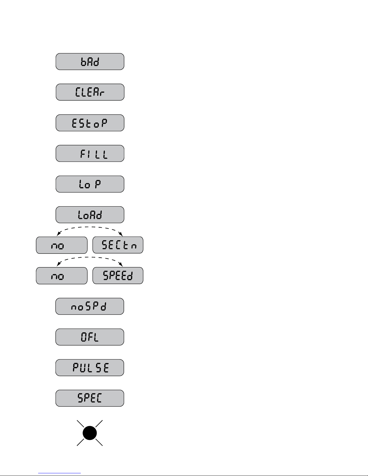
Troubleshooting
Messages / Warnings
CAL
Typically indicates that defaults were entered by powering up with the CAL and
“-” buttons held, but calibration mode was not entered and exited. Cycling power
will not clear the bad CAL message, it can only cleared by entering and exiting
calibration mode.
The message alerts the user that the currently selected counter will be cleared
if held for 2 seconds. Also serves as a reminder to use “+” button to select
counters.
Had an Emergency Stop. Check Seed Shaft (Flow) Sensor. Cleared by
turning all used Sections o, going to HOLD or cycling power.
One or more Seed Bins are near empty.
Low Power. Check all power and ground connections.
Has loaded Default Cal factors (appears when default calibration factors are
loaded by holding CAL and “-” buttons while turning the console on).
In Rows/Section Cal Mode, and no Sections are turned on.
In RATE mode and have no Speed, regardless of all other conditions.
In METER CAL TEST but have not yet enter a Test Speed.
Counters (DISTANCE or AREA or WEIGHT) have overowed their maximum.
RESET (see pages 26-27) to clear counters and resume counting.
Displays for 1.5 seconds upon powering up.
“Special” Calibration mode is active. Appears when entering Special Calibration
mode (hold AUTO/MAN and CAL buttons while turning console on).
Warn LED ashes when the Rate error is over 10% in AUTO or if no ow input
(when there should be) in MAN. On steady when in CALIBRATE or
“SPECIAL”CALIBRATE or Test Speed.
27

Troubleshooting (cont)
General
All DrillMaster consoles are tested prior to packaging, so
unless there has been damage in shipment you can be
confident that everything will be operational when you
receive it.
However, if you do encounter a problem that appears to be
related to equipment failure, PLEASE DO NOT OPEN THE
CONSOLE. Your system is protected by a warranty, and
Micro-Trak will gladly correct any defect.
Many problems are the result of mistakes in installation or
operation. Before returning any parts for service, carefully
check your installation and review the operating instructions.
For easy-to-follow guidelines, refer to the troubleshooting
section which follows.
CONSOLE APPEARS DEAD
Using your test light, check for 12 volts at the power source.
Also check for damaged power cable or reversed terminals.
(Console requires 12 volts for proper operation). Check
connections to ignition or power switch.
SPEED IS ALWAYS ZERO OR ERRATIC
Check for properly calibrated wheel circumference.
Review speed sensor installation. Check for proper mounting,
alignment and spacing of speed sensor in relationship
to magnet assembly. Make sure magnet polarities are
alternated. Also check cable for breaks or incomplete
connection. For more suggestions on solutions to speed
problems, see Hall-effect sensors and console inputs on
pages 30-31.
DISTANCE COUNT IS INACCURATE
Wheel circumference was incorrectly measured or entered.
Review calibration, re-adjust and test.
AREA COUNT IS INACCURATE
Implement width or wheel circumference was measured
incorrectly or programmed incorrectly. Go back through
the original procedures, make changes, and test for acre
(hectare) count again. (Make sure no width is entered for
unused booms.) Verify accuracy with formula:
NO READOUT OF POUNDS KG, OR POUNDS KG
PER MINUTE
Check to see that the hydraulic system and equipment is
operating properly.
Check cable for breaks or incomplete connection.
Flow rate may be too low to register a reading.
SECTIONS SHUTOFF
If you are in AUTO with no speed, the sections will shut-off.
CONSOLE IS ERRATIC IN OPERATION
If you have a two-way radio, it may be mounted too close to
the console. Keep all DrillMaster cables away from the radio,
its antenna and power cable.
Ignition wires may be causing the console to malfunction.
Keep DrillMaster cables away from ignition wires, or install
ignition suppressor.
Reroute all cables away from electric solenoids, air
conditioning clutches and similar equipment.
Check the CONTROL SPEED calibration number in “Special”
Calibration. If the RATE tends to overshoot or oscillate, the
CONTROL SPEED setting may be too high for the control
valve being used; reduce the CONTROL SPEED setting by 1
(range is -4 to +3).
DISPLAYED MEASUREMENTS DO NOT MAKE SENSE
The console may be in the incorrect measurement mode
(English or metric). See page 14 for instructions.
DISPLAY READS “OFL”
DISTANCE, AREA, and VOLUME counters read OFL when
they have exceeded their maximum count. Reset to zero to
resume counting.
SYSTEM OPERATION CONTROL IS SLUGGISH IN
AUTOMATIC MODE
Increase the CONTROL SPEED setting in “Special”
Calibration.
Acres = Distance x Width in feet/43560
Hectares = Distance x Width in meters/10,000
28

Troubleshooting (cont)
Checking Individual Components
CONSOLE
The only way to field test a console is to con nect it to a
harness on a vehicle with a known working console or install
it on an E-POP (Elec tron ic Point of Purchase) dis play stand.
HARNESS
The harness can be checked using an ohm me ter or continuity
tester. The main wiring diagram shows the pin out of all
connectors. See page 7 and 9.
ELECTRICAL INTERFERENCE
Erratic operation of the system may be the result of electrical
interference from ignition wires or inductive loads (electrical
clutch, fan, solenoid, etc). Always try to route wires as far
away from suspect areas as possible. If problems occur, you
may need to relocate the console and/or wiring harness, or
install a noise suppressor.
POWER
Check power source with a test light. If there is no pow er,
trace cable toward battery look ing for breaks. Also check any
fuses or circuit break ers that supply pow er to the console.
ACCESSORY POWER
The speed, flow and run/hold cables all have an ac ces so ry
power wire. Check for 12 volts between B (usu al ly white) and
C (usually black) of these con nec tors. If power is not present,
make sure the ac ces so ry pow er wire is not open or shorted
to ground or to another wire. If this wire has a prob lem, the
con sole may ex hib it erratic behavior or not function at all.
RUN/HOLD HALLEFFECT SENSOR
CAUTION: Improper connection or voltage could damage the
Hall-Effect sensor. The Hall-effect sensor works similar to
a reed switch, but requires power in order to function. This
particular type of Hall-effect sensor “closes” when near the
south pole of a magnet and is otherwise “open”.
Ground pin C (black) and connect clean 12 volts to pin B
(white) of the Hall-effect sensor cable. Connect the positive
lead (red) of an ohmmeter or continuity tester to pin A (red)
and the negative lead (black) of the ohmmeter or continuity
tester to pin C (black) of the Hall-effect sensor cable.
Holding the tip of the sensor up to the south pole of a
magnet should result in a very low resistance (around 300
ohms). Taking the sensor away from the magnet should
result in a very high resistance (infinite).
MAGNETIC HALL-EFFECT SPEED AND FLOW SENSORS
CAUTION: Improper connection or voltage could damage the
Hall-effect sensor.
The Hall-effect sen sor works similar to a reed switch, but
re quires pow er in order to func tion. Also, this par tic u lar type
of Hall-effect sen sor re quires al ter nat ing magnetic po lar i ties
in or der to switch. This means that the north pole of a magnet will “open” the Hall effect and the south pole of a magnet
will “close” the Hall effect.
Ground pin C (black) and connect clean 12 volts to pin B
(white) of the Hall-effect sensor cable. Con nect the positive
lead (red) of an ohmmeter or con ti nu ity tester to pin A (red)
and the negative lead (black) of the ohmmeter or continuity
tester to pin C of the Hall-effect sensor cable.
Holding the tip of the sensor up to the north pole of a magnet
should result in a very high re sis tance (in fi nite), while holding
the tip of the sensor up to the south pole of a magnet should
result in a very low resistance (around 300 ohms).
VANSCO RADAR SPEED SENSOR
Carefully check your installation and operating instructions.
The following are tips for troubleshooting;
1. Disconnect the radar adapter cable from the console
harness.
2. Check for 12 VDC between pins B and C of the main
harness connector (yellow tie). If not present, console
or harness may be defective.
3. Using a jumper wire (paper clip bent into a “U”), rapidly
short together positions A and C of the main harness
speed connector (yellow tie) several times. The console
should respond with some speed reading. If not, the
console or harness may be defective.
4. Reconnect the radar adapter cable to the main harness
speed connection (yellow tie).
5. Disconnect the radar from the radar adapter cable.
6. Check for 12 VDC between pins 1 and 3 of the radar
adapter connector. If it is not present but was present
in step 2, the radar adapter cable may be defective.
7. Using a jumper wire (paper clip bent into a “U”), rapidly
short together positions 2 and 3 of the radar connector
(round 4-pin) several times. The console should respond
with some speed reading. If not but had a reading in
step 3, the radar adapter cable may be defective.
8. If system passes all above tests, the radar may be
defective.
29

Troubleshooting (cont)
Checking Console Inputs
CONSOLE INPUTS
If there is no response from any of the following tests, refer
to the main wiring diagram to locate the next connector in
line to ward the con sole and repeat the test at that con nec tor.
If there is a response at that connector, the problem may be
in the cable between the two connectors (or the con nec tors
themselves).
SPEED INPUT
Turn rotary switch to speed po si tion and dis con nect the
speed sensor (yel low tie) from the main harness. Check
for 12 volts between pins B (white) and C (black) of the
main harness speed cable (yellow tie). Using a clip lead
or other jumper wire (such as a paper clip bent in a “U”),
several times rap id ly short to geth er pins A (red) and C
(black) of the 3-pin connector (See Illustration 7). The
console should respond with some speed read ing.
FLOW INPUT
Turn rotary switch to WEIGHT/MINUTE and disconnect
the flow sen sor (green tie) from the main harness. Check
for 12 volts be tween pins B (white) and C (black) of the
main harness flow cable (green tie). Using a clip lead or
other jumper wire (pa per clip bent in a “U”), several times
rapidly short together pins A (red) and C (black) of the
3-pin connector. The con sole should re spond with some
flow rate reading.
Illustration 7
CBA
Three-Pin Connector
REMOTE RUN/HOLD INPUT
Disconnect the remote run/hold sensor (or jumper cover)
from the main harness.
Check for 12 volts between pins B (white) and C (black)
of the main harness remote run/hold cable (grey tie).
Placing a clip lead or other jumper wire (such as a
paper clip bent in a “U”) between pins A (red) and C
(black) of the main harness run/hold connector (gray tie)
should turn ON the “HOLD” icon on the console display.
Removing the jumper should turn OFF the “HOLD” icon
on the console display.
PWM VALVE CONTROL SIGNAL
With the console turned ON, put the console in MANUAL
mode, place the remote Run/Hold switch in the RUN position
and turn at least one boom switch to ON. Using a voltmeter
or simple test light, connect the positive lead from the
test light or voltmeter to Pin A on the PWM Control Valve
connector and the other lead to Pin B. Holding the “+”
button should cause the voltmeter voltage to increase from
about 4 volts to about 12 volts and the test light should go
from dim to bright.
PWM VALVE
To operate the valve in a manual
mode remove the cover on top
of the cartridge assembly using
a 1 1/16” wrench.
The knurled stem on top should
be turned counter clockwise
against the stop for normal
operation of the PWM cartridge.
To adjust the hydraulic oil flow
manually turn the stem clockwise
until the desired hydraulic
motor RPM is achieved. Turn
clockwise approximately 1 turn
to reach start point. Continue
another approximately 5 turns
for maximum oil flow.
RPM Flow Control Valve
Description
A solenoid-operated,
electrically-variable, three port,
pressure-compensated, spooltype, normally closed when
de-energized, proportional flow
control valve.
Porting:
1 - Inlet
2 - Bypass
3 - Regulated Flow
In an open center configuration the Bypass post can be
blocked.
To test the electrically-variable shift of the spool, remove the
manual override feature on top of the cartridge assembly
using a 1 1/16” wrench. At the console set the system to
manual mode (MAN) and turn the rotary switch to the RATE
position. Turn at least on section switch ON and hold the
“+” for ten (10) seconds. While holding your finger firmly
ion the top of the cartridge assembly, have someone toggle
the console HOLD switch and you should feel the spool shift
slightly, about .040”.
To test the solenoid resistance connect at the solenoid
exposing two male terminals.. Using an ohmmeter measure
the resistance across the terminals. The reading should be
approximately 4.0 ohms.
3
INLET
FLOW
1
BYPASS
2
30

Appendices
31
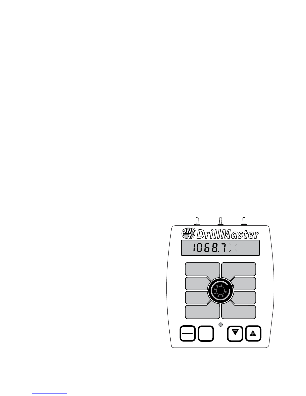
Appendix A
Fine Tuning Speed/Distance Calibration Val ue (With Run/Hold Switch Kit Installed)
This procedure is used to verify the calibration of systems
WITH the Run/Hold Switch Kit or an optional remote run/
hold kit installed. In order to achieve accurate measurements,
each step in this fine tuning procedure should be performed
as precisely as possible.
PREPARATION
• Once the system is fully installed and calibrated, se lect a
straight tract of ground that is similar to your ac tu al field
conditions and as level as pos si ble.
NOTE: Us ing a course with a different ground sur face,
such as a hard-surface road, will re sult in dif fer ent readings than exact field con di tions.
• Measure a distance of 1000 feet (500 meters). Clear ly
mark the beginning and end points with flags or something highly visible to the operator.
PROCEDURE
1. With the console turned ON, place the Run/Hold switch
in the HOLD position. The HOLD icon will be displayed.
Turn the rotary dial to the DISTANCE position. Be sure
the display shows 0. If not, reset the distance counter by
pressing and holding RESET until the display returns to
0 (approximately one second). The word CLEAr will be
displayed when reset is pressed.
2. You are now ready to drive the measured course. Pick
a location on the vehicle to use as a marker for starting
and stopping the distance counting function (door
handle, mirror, step, etc). You should begin driving the
course well ahead of the starting flag and drive past the
ending flag, using the Run/Hold switch to start and stop
the counting function. It is not recommended to start
from a dead stop at the starting flag and stop at the
ending flag.
3. Place the Run/Hold switch in RUN when the marker
on the vehicle passes the starting flag to activate the
distance counting function. The console display numbers
will increase, adding to the distance total as you drive.
Drive the pre-measured course and place the Run/Hold
switch in HOLD, when the marker on the vehicle passes
the ending flag, to stop the distance counting function.
The console display should read HOLD. See Illustration
to the right. Stop the vehicle in a level and safe area and
continue with this procedure.
4. With the rotary dial still at DISTANCE (SPEED CAL), press
and hold the CAL key for one second. Once the con sole
is in “CAL,” CAL and the speed calibration value will be
displayed. Momentarily press CAL and the word CAL
will begin to flash and the distance travelled will be
displayed. See Illustration below.
5. When the display shows distance (“CAL” is flashing), veri fy wheth er the number displayed is the ex act dis tance
you drove (with in +/- 1 - 2 %). If not, press the “+” or “-”
key to ad just the fig ure to match the dis tance you ac tual ly drove. If the display reads too high, use the “-” key to
lower the dis played value. If the display reads too low,
use the “+” key to raise the displayed value.
6. When the number shown on the display match es (as
close ly as possible) the ac tu al dis tance driv en, you have
ar rived at the cor rect cal i bra tion val ue. If you can not
adjust the displayed distance to exactly match the actual
dis tance driven, adjust the figure as close as possible
to the actual distance. You may check the calibration
number by momentarily pressing CAL. The word CAL
and the SPEED CAL number will appear. Exit “CAL” by
pressing “CAL” for one second.
The speed sen sor is now calibrated. To verify proper
calibration, repeat the procedure a sec ond time. Write down
the new speed calibration number and keep it in a safe place.
If the cal i bra tion values are ever accidentally changed, you
can simply re-en ter this num ber.
DrillMaster
MANAUTO
CALHOLD
V 1 2 3 4
METER
SPACING
ADJUST
TARGET
CAL
ROW
RATE
RATE
WEIGHT TOTALS
(1) (2) (3)
WEIGHT /
MINUTE
AREA/
HOUR
RATE
AREA TOTALS
(1) (2) (3)
DISTANCE
METER
RPM
SPEED
ROWS/
SECTION
SPEED
CAL
CAL
TEST
TEST
SPEED
32
AUTO
MAN
CAL
RESET

Appendix B
Cal Test Fine Tuning Calibration Values
For maximum accuracy the user must follow the steps below.
1. Before starting the test make sure all cal factors including
Target Lbs/Acre and Sample Size are correct for the Seed
being used. Fill the Drill with enough Seed to perform
the test.
2. Select HOLD (Remote or Wireless), or turn all Sections o
on the Console.
OPTIONAL: At least one Row must be used. However for
improved accuracy the operator can use multiple containers and perform the test on several rows (in parallel)
to obtain a better average or to test the variation from
one row to another. If comparison of Rows is not needed
and just an overall average is desired then a tarp can be
used to catch the seed from multiple Rows or the entire
Drill but the user will need to divide the total weight
measured by the number of Rows used, to obtain the
‘Weight per Row’.
3. Select CALIBRATE (hold the CAL key for 1 second) and
then select the CAL TEST position. It will display “OFF” indicating it is still inactive.
4. To initialize or start the CAL TEST press the “+” key and
the display will jump to the Sample Size weight (1.00
pound typical) for 4 seconds. This “reminder” conrms
the Sample Size and the operator must use containers
large enough to catch that much seed from the Row
under test. This step will also automatically select AUTO
(AUTO icon on) because the CAL TEST must always be
performed in AUTO. After 4 seconds it will display "No
SPD” (no Speed) as a reminder to do the next step.
5. While still in CALIBRATE, rotate to the ‘Test Speed’ position and enter a Test Speed equal to the desired speed
in the eld. The CAL icon will ash to indicate the ‘Test
Speed’ mode is active. All rotary positions will operate
normally (see Test Speed), except the METER RPM position will now display the “test weight” (instead of RPM).
6. Select the CAL TEST position. This position will display
“No SPD” (no Speed) if a Test Speed was not entered
(Step 5 was skipped). It will display 0.00 lbs if a Test
Speed has been entered and it is ready to count up
to the Sample Size when RUN is selected. Unlike the
normal WEIGHT, it displays the weight with two decimal
places so it can display 1.00 pounds with 1% resolution
for improved accuracy.
7. Place an empty catch pail under the Row (or Rows) to be
tested. OPTIONAL: Use a Tarp if the whole Drill is being
tested for an overall “average”.
8. Run engine at normal operating speed to generate normal hydraulic pressure.
9. Place the Console in Run, or turn the desired Section (or
Sections) on. Auto control will run the Seed Drive Shaft at
the Target Rate and it will continue to run until it has dispensed Sample Size of seed per row (typically 1 pound)
and then it will stop (PWM output will go to zero). During
this time the Weight displayed in the CAL TEST (METER
RPM) position will count up to something close to the
Sample Size (instead of displaying RPM).
10. The Console will automatically stop after dispensing the
Sample Size (Do not select Hold yet).
11. Weigh the Seeds in the Catch pail and it should equal the
value shown in the display (close to the Sample Size).
OPTIONAL: If multiple Rows were used then each Row should
equal the value shown in the display (close to the Sample
Size). If multiple Rows were used then record the Weight for
each Row. Add all Rows together and divide by the number
of Rows to obtain an Average Weight per Row. Each Row can
then be compared to the Average to compute the percent
variation between Rows and nd the highest and lowest.
If a tarp was used to capture multiple Rows, or the entire Drill,
then divide the Total weight by the number of Rows used to
obtain the Average Weight per Row. This will provide a very
accurate average but this method cannot be used to nd the
variation between Rows.
12. Use the “+”/”-” keys to adjust the displayed weight until
it matches the actual sample weight measured. This will
adjust the Meter Cal value. Press the Cal Key to exit the
Cal Test Mode.
In Step 9 the displayed weight will not equal the Sample Size
exactly. Some error should be expected due to start up and
stopping delays plus inertia and friction etc. It is much more
important that the Seeds captured from each Row weigh the
same as the displayed weight rather than the Sample Size.
When the Console is rst placed in Run in step 9, it may take
a little time for auto control to reach target. This should have
minimal aect on the results.
In Step 11, if there is a wide variation between Rows, or between Sections, then the Seed Metering mechanism may be
improperly set (wrong Slot width etc.) or some Rows may
be dirty or worn so they miss or add some seeds. The operator should clean and/or repair those Rows or adjust the Slot
width and repeat the above test.
For improved accuracy the Sample Size can be increased.
For example increasing the Sample Size from 1.00 pounds
to 10.00 pounds increases the resolution from 1.0% to 0.1 %.
The scale used to weigh the seed must also be accurate and
have the same or greater resolution.
It should be noted that steps 4 and 5 cannot be reversed. If
Test Speed is selected rst then it will simply perform the normal ‘Test Speed’ functions (including the display of RPM), and
the “Cal Test” mode cannot be started. However, when “Cal
Test” is started rst (step 4) then when “Test Speed” is selected
(step 6) it will operate a little dierent. Instead of displaying
RPM it will display the Cal Test weight as described above.
33

Appendix C
Meter Cal Fine Tuning Calibration Values
1. Back the applicator up to a material pile for unloading or
lay out a tarp to catch the seed or place a container under
each Row. Make all adjustments to the Drill are complete
and the same for all Rows.
2. Select the WEIGHT/MINUTE position and use the MAN
UAL CONTROL to adjust the rate to a typical value for
your application, then select Hold.
RECOMMENDED - Use Test Speed and allow the controller to reach your Target Rate using Auto control
then select Hold.
3. Weigh the applicator carefully noting this as the “Beginning Weight” and back the applicator up to a material
pile (or tarp or containers) for unloading again.
4. Clear a Weight counter by selecting the Weight position
and pressing “-” (Reset) key for 1 second (while still in
Hold). NOTE: Any of the 3 Weight counters can be used.
Empty the containers if they are were used.
5. Go to Run and allow at least ten pounds of material to unload, which will be recorded in Weight. A display of 10.0
lbs will provide 1% resolution. If 100.0 lbs is dispensed
then the resolution and accuracy increases to 0.1%. The
Metering Slot mechanisms are speed sensitive therefore
Test Speed and Auto mode should be used so the Drill
runs at the Target rate for the desired ground speed.
6. Select HOLD to stop the applicator and weigh it again.
Subtract this ending weight from the beginning weight
to compute the actual weight of material that was unloaded. If containers were used then weigh each one and
record the Weight per Row for each Row and add all Rows
together to compute the Total Weight dispensed. The
WEIGHT counter should equal this amount and the following steps will ne-tune METER CAL so it does match.
7. Start Calibrate. (While in Hold, press CAL key for 1 sec).
8. Select the METER CAL position and the current METER
CAL value will be displayed. Press the CAL key to toggle
the display to show Weight.
NOTE: Pressing the CAL key will toggle between
METER CAL value and Weight.
To remind the user he is still in the CAL Mode, the CAL
icon will turn on when displaying the METER CAL value
and it will ash when displaying Weight.
9. Use the”+”/”-” (Reset) keys to adjust the displayed Weight
until it matches the actual weight computed above. This
will automatically ne-tune the METER CAL value.
10. Press the CAL key again to toggle the display to show the
METER CAL value and write it down for future reference
when this Metering Slot and material is used again.
If containers were used to catch the seed then add the weight
of all Rows and divide by the number of Rows to compute the
average Weight per Row. Then the weight for each row can
be compared to the average to nd the percent variation for
each Row and nd the lowest and highest Row. Rows that are
extra high or low may need cleaning, repair or adjustment.
To make it simpler and more intuitive, the METER CAL value is
always displayed when the rotary switch is rst turned to the
METER CAL position.
For example, assume the METER CAL value is displayed and
the CAL key is pressed to toggle to the Weight value. Then
the switch is rotated to some other Cal factor. When returned
to the METER CAL position it will automatically switch back to
displaying the METER CAL value rather than staying “stuck” in
the Weight display (with the CAL icon ashing).
34
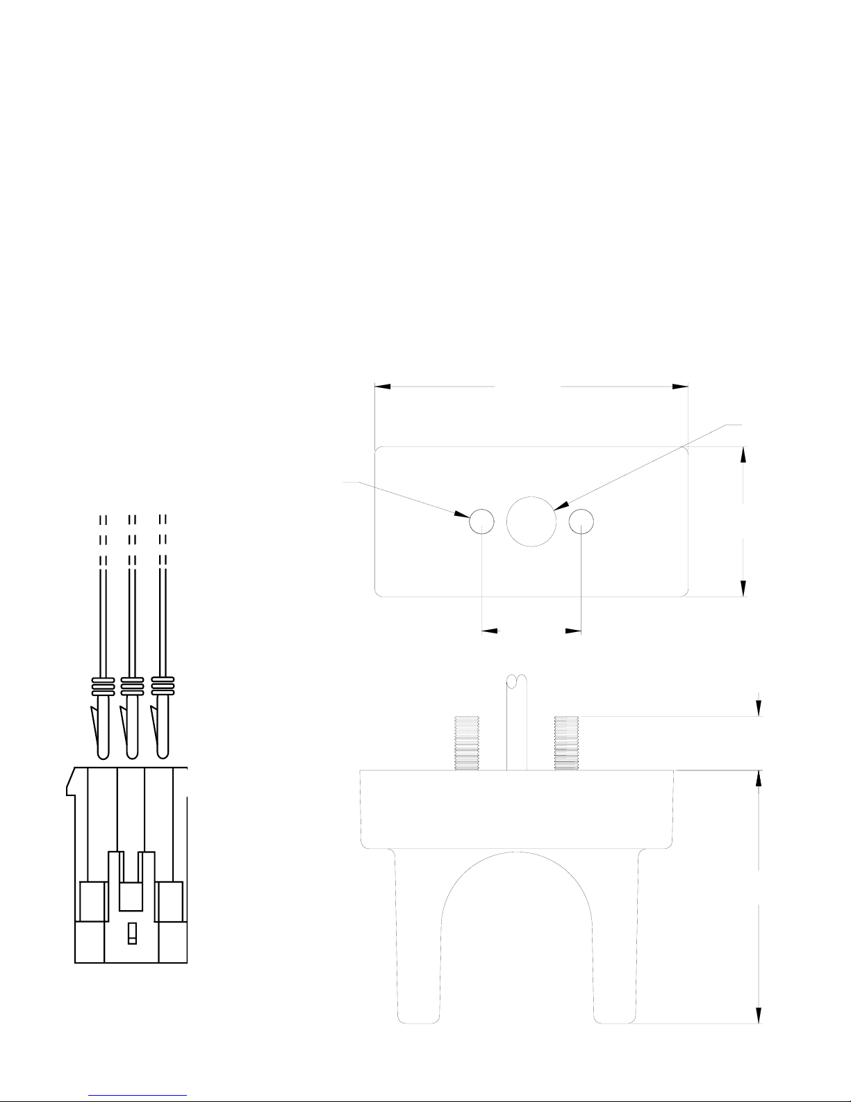
Appendix D
3.15
Ø0.50
)
Bin Level Sensor Kit Installation
INSTALLATION
Mount the bin level sensor(s) at the desired level in the
bin(s). The connector body is supplied loose so a smaller
access hole can be drilled in the bin. The wires (with pins)
can be passed through the access hole, then the pins are
inserted into the connector housing.
Using provided template (on outside of bin) drill two 1/4”
holes 1” apart horizontally. Holes should be at least 2 inches
above the bottom of the bin wall. Drill a 1/2” hole for the
Bin Sensor Cable, centered between the two holes. Run the
Bin Sensor Cable out through the 1/2” hole, from the inside
of the bin. Fit the studs through the two 1/4” holes and
stick the sensor to the inside of the bin. Fasten sensor down
securely with #10 locknuts and washers provided.
Ø0.25 (2 PLCS)
BLACK (GROUND
GREEN (POWER)
RED (SIGNAL)
ELECTRICAL INSTALLATION
Insert the pins into the provided connector housing per the
diagram below. Note that the pins must be inserted in the
proper positions or damage may result.
Template
1.50
C
Insert pins into
connector housing
until they “click”
into place. Install
TPA (white piece)
to back of housing.
Wire Pin
Black C
Green B
B
Red A
A
1.00
0.54
2.54
35

Appendix E
In-Cab John Deere Metri-Pack Connector
p2
Radar Adapter Cables
Ground
Common
1. Ground
2. Signal
3. +12 Volts
4. N/C
2
8000/9000 Series
Signal
B A
DICKEY-john Radar Amp Connector
2 1
4 3
P/N 14812
DICKEY-john Radar Cannon Connector
1
P/N 14810
3
4 2
1
RADAR CONNECTOR SIGNAL PIN
DICKEY-john
DICKEY-john
DICKEY-john
DICKEY-john
DICKEY-john
In-Cab JD (8000 & 9000’s
Magnavox & Phillips
Raven
1
Vansco Am
Amp 2
Cannon 3
Deutsch 3
Ford 2
Packard B
Metri-Pack A
Packard C
Conxall 3
In-Cab John Deere “Y” Connector
2
P/N 14811
3 4
1. +12 Volts
2. Ground
3. Signal
4. Enable
1 4
2 3
1. 12 Volts
2. +12 Volts
3. Signal
4. Ground
1 2
4 3
1. Ground
2. Signal
3. +12 Volts
4. Enable
P/N 14813
4
DICKEY-john Radar Deutsch Connector
4 1
3 2
P/N 14814
DICKEY-john Radar Ford Connector
1
3
2
4
3
DICKEY-john Radar Packard Connector
B
A
A B
C D
A. Ground
B. Signal
C. 12 Volts
D. 12 Volts
P/N 14815
D C
Magnavox & Phillips Radar Packard Connector
B A
A B
C D
A. 12 Volts
B. 12 Volts
C. Signal
D. Ground
P/N 14818
D
Raven Radar Conxall Connector
2
3
1
C
3
Vansco Radar Amp Connector
P/N 14926
1
1. Ground
2. 12 Volts
3. Signal
36
P/N 14817
2

Appendix F
Conversion Chart
English to Metric
When You Know Multiple By To Find
LINEAR MEASUREMENT
inches 25.4 millimeters
feet 0.305 meters
yards 0.914 meters
miles 1.61 kilometers
LAND MEASUREMENT
square inches 645.16 square millimeters
square feet 0.093 square meters
square yards 0.836 square meters
acres .405 hectares
square miles 2.59 square kilometers
LIQUID MEASUREMENT
uid ounces 29.57 milliliters
pint 0.473 liters
quart 0.946 liters
Metric to English
When You Know Multiple By To Find
LINEAR MEASUREMENT
millimeters .039 inches
meters 3.28 feet
meters 1.09 yards
kilometers .62 miles
LAND MEASUREMENT
square millimeters 0.00155 square inches
square meters 10.764 square feet
square meters 1.195 square yards
hectares 2.47 acres
square kilometers 0.386 square miles
LIQUID MEASUREMENT
milliliters 0.034 uid ounces
liters 0.529 pint
liters 0.264 quart
gallons 3.785 liters
VOLUME
cubic feet 0.028 cubic meters
cubic yards 0.765 cubic meters
DRY MEASUREMENT
quart 1.101 liters
peck 8.810 liters
bushel 35.239 liters
FUEL CONSUMPTION
10 miles per gallon = 4.25 kilometers per liter
liters 2.64 gallons
cubic meters 35.314 cubic feet
cubic meters 1.307 cubic yards
liters 1.101 quart
liters 8.810 peck
liters 35.239 bushels
Conversion Abbreviations
Symbols Symbols Symbols
in. = inches pt. = pintkm = kilometers
ft. = feet qt. = quart mm2 = square millimeters
yd. = yards gal. = gallon m2 = square meters
ml. = miles ft3 = cubic feet ha = hectares
in2 = square inches yd3 = cubic yards km2 square kilometers
ft2 = square feet pk. = peck ml = milliliters
yd2 = square yards bu. = bushel l = liters
ml2 = square miles mm = milliliters dal = dekaliters (10 liters)
oz. = uid ounces m = meters m3 = cubic meters
VOLUME
DRY MEASUREMENT
FUEL CONSUMPTION
10 kilometers per liter = 23.5 miles per gallon
37

Appendix G
Replacement Parts List
The following replacement parts are available from your dealer or distributor, or contact us:
Micro-Trak Systems, Inc.
P.O. Box 99, 111 East LeRay Avenue
Eagle Lake, MN 56024-0099
When ordering parts, please list the model number of your console, and the description and part number of each part
that you want to order.
Part Number Description
01531 Speed sensor kit
01535 Remote run/hold sensor kit
10013 Speed sensor mount bracket
12069 Magnet kit (6 magnets per kit)
12888 Console mount knob
12889 Console mount washer
12910 14” Black plastic cable ties (bag of 10)
13096 5-foot Hall-effect Speed/Flow Sensor Cable with threaded sensor, nut and female connector
13181 Console mount kit*
13226 5-foot remote run/hold sensor cable
14315 Power cable
17881 Cable, DrillMaster Section 1 & 3 - Multi Section
17882 Cable, DrillMaster Section 2 - Multi Section
17883 Cable, DrillMaster PWM and R/H - Multi Section
17884 Cable, DrillMaster - Single Section
17899 DrillMaster Console
21612 DrillMaster Multi-Section Module
21778 Kit, Run/Hold Switch
21779 Power Switch
50318 DrillMaster Reference Manual
Optional 2-Pin, 3-Pin and 10-Pin Metri-Pack 150 extension cables:
Part No. M/P 2-Pin Part No. M/P 3-Pin Part No. M/P 10-Pin Part No. M/P 10-Pin
13200 5-foot 13205 5-foot 13220 5-foot 17095 30-foot
13201 10-foot 13206 10-foot 13221 10-foot 17096 40-foot
13202 15-foot 13207 15-foot 13222 15-foot 17269 45-foot
13203 20-foot 13208 20-foot 13223 20-foot 14142 50-foot
13204 25-foot 13209 25-foot 13224 25-foot
*The Console Mount Kit is available only as a kit, some parts are not available in individual components.
Parts and design specifications subject to change without notice.
38


Manufactured in U.S. A. by
111 East LeRay Ave., Box 99, Eagle Lake, MN 56024-0099
Toll-Free: 800-328-9613
507-257-3600 • Fax 507-257-3001
www.micro-trak.com • trakmail@micro-trak.com
Printed in U.S.A.
Copyright © 2019 Micro-Trak® Systems, Inc. • P/N 50318 • 021919
 Loading...