

Page 1

OMNIScanner
TM
the future of network testing
OMNI
Fiber
TM
featuring
Page 2

OMNI
Scanner2
TM
OMNI
Scanner LT
TM
OMNI
Fiber
TM
7IAH/KE@A
ENGLISH
A Guide to using the Microtest OMNI
Scanner
to install,
manage, and troubleshoot high performance cabling systems
as well as multi- and single-mode fiber.
OMNI
Scanner
verifies installed links against all common
cabling and network standards including Category 6/Class E
and Gigabit Ethernet.
OMNI
Fiber
verifies installed links against TIA and ISO stan-
dards, as well as other fiber network application requirements.
2950-4500-06E Rev. 01 4/01
Page 3

TOC - 1
OMNIScanner User Guide
Contents
Chapter 1 - Introduction .................................................................................. 1 - 1
The Digital Solution for Fiber and Copper ......................................................1 - 1
The Graphical User Interface .......................................................................... 1 - 1
OMNIRemote...................................................................................................1 - 1
OMNIFiberTM ..................................................................................................1 - 2
ScanlinkTM Tools Software .............................................................................1 - 2
OMNIScanner’s Display ..................................................................................1 - 3
OMNIScanner’s Keypad ..................................................................................1 - 4
OMNIRemote’s LED Indicators ....................................................................... 1 - 7
OMNIRemote Keys..........................................................................................1 - 7
When To Use OMNIRemote ............................................................................1 - 8
Displaying OMNIScanner and OMNIRemote Results .................................... 1 - 8
OMNIFiber MM LED Indicators..................................................................... 1 - 10
OMNIFiber SM LED Indicators ..................................................................... 1 - 10
Attaching the OMNIScanner Fiber Adapters.................................................1 - 11
Attaching the Microtest Connector Adapter................................................... 1 - 11
Editing With OMNIScanner........................................................................... 1 - 12
Predefined Lists....................................................................................... 1 - 12
Editing Numeric Fields with the Spin Control ......................................... 1 - 12
Editing Alphanumeric Fields.................................................................... 1 - 13
Technical Support ......................................................................................... 1 - 14
Product Versions .......................................................................................... 1 - 15
Chapter 2 - Getting Started Twisted Pair Networks .........................................2 - 1
Charging OMNIScanner’s Battery ................................................................... 2 - 1
OMNIScanner’s Project Screen.......................................................................2 - 1
Certification of Network Installations ............................................................... 2 - 2
Setting the Reference...................................................................................... 2 - 3
Project Selection .............................................................................................2 - 4
Running an Autotest for Twisted Pair Cabling ................................................ 2 - 5
Saving Twisted Pair Autotest Results ..............................................................2 - 6
Viewing Twisted Pair Autotest Results ............................................................2 - 7
Typical Test Configurations for Twisted Pair Cabling................................... 2 - 10
Basic Link..................................................................................................2 - 11
Basic Link with 110 Block and Modular 8 Jack ......................................2 - 11
Full Channel with Modular 8 Jacks ......................................................... 2 - 12
Permanent Link ....................................................................................... 2 - 12
Page 4

OMNIScanner User Guide
TOC - 2
Chapter 3 - Getting Started Fiber Optic Networks..........................................3 - 1
Charging OMNIScanner’s Battery ...................................................................3 - 1
OMNIScanner’s Project Screen....................................................................... 3 - 1
Certification of Fiber Installations ................................................................... 3 - 2
Preparation .................................................................................................3 - 2
Certification .................................................................................................3 - 2
Completion ..................................................................................................3 - 2
Setting the Reference for Fiber Optic Cabling................................................3 - 3
Project Selection .............................................................................................3 - 4
Running an Autotest for Fiber Optic Cabling.................................................. 3 - 5
Preparing an Autotest ....................................................................................3 - 5
2 JUMPER METHOD AUTOTEST .................................................................3 - 5
1 JUMPER METHOD AUTOTEST .................................................................3 - 6
3 JUMPER METHOD AUTOTEST .................................................................3 - 6
Loopback Autotest using OMNIFiber Main ................................................3 - 7
Running a Fiber Autotest ................................................................................ 3 - 8
Fiber Autotest Results ..................................................................................... 3 - 9
Chapter 4 - Setup ...............................................................................4 - 1
Configuring OMNIScanner ..............................................................................4 - 1
Set Reference..................................................................................................4 - 2
Set Reference with the OMNIFiber Adapters................................................4 - 2
Autotests ..........................................................................................................4 - 3
Viewing Details for Copper and Fiber Autotests ..........................................4 - 3
Cables .............................................................................................................4 - 5
Projects ............................................................................................................4 - 7
Editing a Circuit ID ..........................................................................................4 - 8
Configurations .............................................................................................. 4 - 10
Autotest Run Options.................................................................................... 4 - 10
Autotest Save Options ...................................................................................4 - 11
User Options ................................................................................................. 4 - 12
Adapter Usage ............................................................................................. 4 - 13
Remote Info.................................................................................................. 4 - 13
Fiber Adapter Info ........................................................................................ 4 - 14
Format MMC ................................................................................................. 4 - 14
Regional Settings ......................................................................................... 4 - 14
Chapter 5 - Measurements .................................................................5 - 1
Performing Individual Measurements with OMNIScanner ............................. 5 - 1
Measuring T wisted Pair Cabling....................................................................5 - 1
Measuring Fiber Optic Cabling ......................................................................5 - 2
Measuring Coaxial Cabling ............................................................................5 - 2
Selecting an individual T est ...........................................................................5 - 2
Page 5

TOC - 3
OMNIScanner User Guide
General Information ........................................................................................5 - 3
Twisted Pair Measurements with OMNIScanner ...................................5 - 5
Wiremap ......................................................................................................5 - 5
Length/Delay................................................................................................5 - 5
NEXT ............................................................................................................5 - 6
Attenuation ..................................................................................................5 - 7
Return Loss .................................................................................................5 - 8
ELFEXT .........................................................................................................5 - 9
ACR/Bandwidth ........................................................................................ 5 - 10
Resistance ................................................................................................5 - 11
Power Sum NEXT......................................................................................5 - 11
Power Sum ELFEXT ................................................................................. 5 - 12
Power Sum ACR....................................................................................... 5 - 13
Fiber Optic Measurements with OMNIFiber ........................................... 5 - 14
Length/Delay............................................................................................. 5 - 14
Loss .......................................................................................................... 5 - 14
Power Meter............................................................................................. 5 - 15
Coaxial Measurements with OMNIScanner ......................................... 5 - 16
Coax Tests................................................................................................ 5 - 16
Tracer/Toner ............................................................................................. 5 - 16
Chapter 6 - Diagnostics .....................................................................6 - 1
OMNIScanner’s Diagnostic Functions ............................................................ 6 - 1
Wiremap ..........................................................................................................6 - 1
Wiremap Displays.......................................................................................6 - 2
TDNXT .............................................................................................................6 - 3
Using TDNXT to Diagnose a Link ...............................................................6 - 4
TDNXT Examples ........................................................................................6 - 5
TDRL ...............................................................................................................6 - 6
Using TDRL to Diagnose a Link ..................................................................6 - 8
TDRL Examples ...........................................................................................6 - 8
Impulse Noise .............................................................................................. 6 - 10
Cable Trace...................................................................................................6 - 11
Office Locator.................................................................................................6 - 11
Chapter 7 - Results.............................................................................7 - 1
Autotest Results ...............................................................................................7 - 1
Viewing Autotest Results .................................................................................7 - 2
Results stored on a MultiMediaCard ............................................................... 7 - 4
Chapter 8 – Fiber Optic Reference Methods .................................................. 8 - 1
Establishing the Reference ............................................................................. 8 - 1
The Launch/Jumper Cable .............................................................................8 - 2
Page 6

OMNIScanner User Guide
TOC - 4
The Reference Methods ..................................................................................8 - 2
One Jumper Reference Method ................................................................8 - 3
Two Jumper Reference Method ................................................................8 - 4
Three Jumper Reference Method .............................................................8 - 5
T wo Jumper Reference Method in Loopback Mode.................................8 - 6
Chapter 9 - Uploading and Printing ................................................................9 - 1
ScanlinkTM Tools ............................................................................................9 - 1
Chapter 10 - Updating Scanner Software ................................................... 10 - 1
Downloading Software from the Microtest WWW site .................................. 10 - 1
Updating OMNIScanner and OMNIRemote Software ................................. 10 - 1
Chapter 11 - MultiMediaCard.........................................................................11 - 1
Portable Data ................................................................................................11 - 1
MultiMediaCard Maintenance........................................................................11 - 2
The MMC Structure ........................................................................................1 1 - 2
Chapter 12 - Universal Serial Bus Port ........................................................ 12 - 1
Installing the USB Driver .............................................................................. 12 - 1
Uploading OMNIScanner2 Test Results to the PC ...................................... 12 - 3
Downloading Configurations to OMNIScanner2 .......................................... 12 - 4
Remote Controlling OMNIScanner2 ............................................................ 12 - 5
Appendix A - Technical Specifications ........................................................... A - 1
Appendix B - Batteries.................................................................................... B - 1
Appendix C - OMNIFiber PASS/FAIL Criteria ................................................C - 1
Appendix D - Cable Pin-Outs.........................................................................D - 1
Serial Cable DB-9 Male to DB-9 Female Pin-outs ........................................ D - 1
Serial Cable DB-9 Male to DB-25 Female Pin-outs ......................................D - 1
Cable Pin-Out Signals ................................................................................... D - 2
Page 7

1 - 1
OMNIScanner User Guide
Chapter 1 - Introduction
The Digital Solution for Fiber and Copper
OMNI
Scanner
is the most advanced hand-held certification and diagnostic
tool for the verification of copper links. The Category 7, 6, 5E (Enhanced),
5 and ISO Class F, E, D, and C tester has an extended frequency range of
300 MHz. OMNI
Scanner
provides full software compliance with TIA and
ISO/IEC requirements for measurement reporting and analysis (including
Length, Delay , ACR, NEXT, ELFEXT, Return Loss, Resistance, PSNEXT,
PSACR, PSELFEXT and Attenuation). In addition, OMNIScanner measures Length, Delay , Impedance, and Resistance on coaxial cabling.
OMNI
Fiber
MM (multimode) and OMNI
Fiber
SM (single-mode) expand the
tester’s capabilities to certify installed fiber links against TIA and ISO
standards. Fiber cabling can be verified at 850, 1300, 1310, and 1550 nm
wavelengths.
The Graphical User Interface
OMNI
Scanner
’s graphical user interface consists of a backlit LCD display ,
quick access menus, arrow keys, and descriptive menu options that guide
you through certifying or troubleshooting cabling systems.
OMNIRemote
For test and certification of twisted pair cabling, the OMNI
Scanner
requires
the OMNI
Remote
unit at the opposite end of the cabling link under test.
OMNI
Scanner
communicates with OMNI
Remote
to obtain status and
perform measurements from both ends of the link.
OMNI
Remote
is equipped with a speaker to generate tones, and several
colored LEDs to indicate overall test results and status.
Page 8

OMNIScanner User Guide
1 - 2
OMNIFiber
TM
OMNI
Fiber transforms
OMNI
Scanner and OMNIScanner2
into a fiber optic
tool for testing and certification of multimode and single-mode fiber
premise networks. OMNI
Fiber
consists of two test heads that attach directly
onto OMNI
Scanner
and OMNI
Remote
to become a part of each unit. Using
the 1-Button Autotest feature, OMNI
Fiber
measures loss and length over
two fibers simultaneously . The measurements are compared against the
selected LAN standard for instant P ASS/F AIL analysis. OMNI
Fiber
measures loss at 850 and 1300 nm over multimode fiber and at 1310 and 1550
nm over single-mode fiber .
Up to 1000 Autotests can be saved to nonvolatile memory . Saved results
can be easily uploaded to the PC with Scanlink
TM
software.
ScanlinkTM Tools Software
PC-based software expands OMNI
Scanner’s
user interface and aids with
the management of projects. Scanlink Tools consist of the OMNIScanner
Configuration software, the Scanlink Upload software, and the OMNIScanner Remote Control software. These programs allow you to store,
retrieve, manage, edit and print network cabling information. Scanlink Tools
provide the ability to create professional reports, remote control OMNI-
Scanner
, and define cable and project configurations that can be down-
loaded to OMNI
Scanner
.
Page 9

1 - 3
OMNIScanner User Guide
OMNIScanner’s Display
Scanner Display Function
1-2 or 12/36: The paired numbers in the display indicate wire pairs.
For example, 1-2 indicates the wire pair of pins 1 and
2. 12/36 indicates two wire pairs tested, the first pair
of pins 1 and 2, and the second pair of pins 3 and 6.
Pop-up lists: Pop-up lists are available by pressing ENTER when
the cursor is located on user definable fields. A
predefined selection list will appear , and the rest of the
display will be inactive.
Spin Control: The spin control is available by pressing ENTER on
editable fields that allow for increasing or decreasing
numeric values by depressing the é or ê keys.
Scrollbars: Use the é and ê keys on the keypad to move up and
down in a scrollable screen.
Graph: Use the ç or è to move the graph cursor on the
frequency axis. Use the é or ê to zoom in and out on
graphs.
Page 10
OMNIScanner User Guide
1 - 4
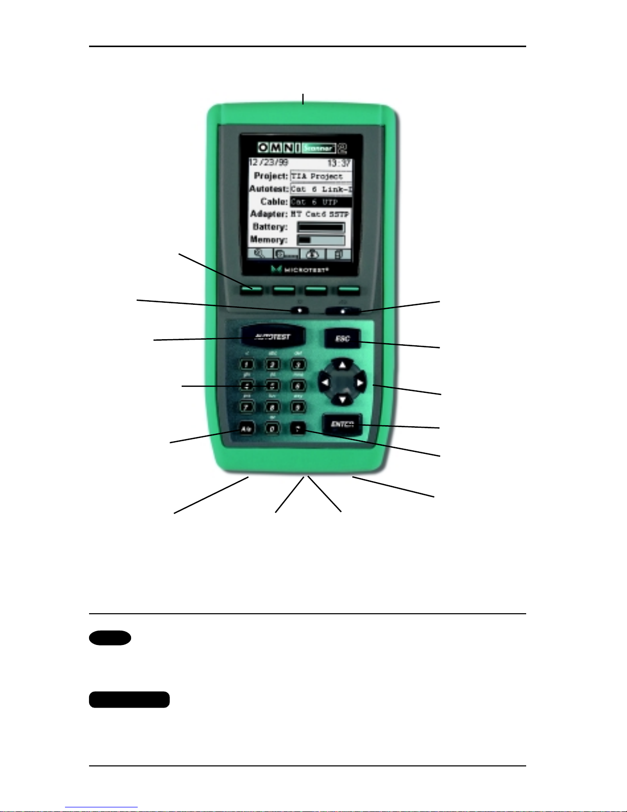
ADAPTER CONNECTOR
FUNCTION KEYS
ON/OFF BACKLIGHT
AUTOTEST ESCAPE
ALPHANUMERIC ARROW KEYS
KEYS
ENTER
UPPER/LOWER
CASE
HELP KEY
SWITCH KEY
AC ADAPTER
USB PORT DB-9 SERIAL MMC CARD
(OMNISCANNER2)
CONNECTOR SOCKET
(OMNISCANNER2)
OMNIScanner’s Keypad
ON/OFF
When turned on OMNI
Scanner
will display the project screen.
Backlight
Press the Backlight key to toggle the backlight between its two levels of
brightness. Press and hold the Backlight key to display the CONTRAST
Page 11

1 - 5
OMNIScanner User Guide
screen. Use the é and ê keys on the keypad to adjust the display contrast. In addition to contrast adjustments, the screen displays hardware
version, software version, serial number information, and the date and time
when the unit was last Factory Calibrated.
AUTOTEST
Autotest
Press the Autotest key to run a custom or predefined Autotest.
ESC
ESC
Press the Escape key to cancel the current operation.
Arrow keys
Press the çèéê arrow keys to navigate within a list, menu, graph, or
editable field.
ENTER
ENTER
When in a selection field press the ENTER key to open the listbox and then
select the highlighted item as the new default. When in an editable field
press the ENTER key to start the edit process, and press ENTER again
when finished with the editing process.
Alphanumeric Keys
1
Use the 0 through 9 keys to enter numeric and alphabetic characters in editable fields. Alphabetic and special characters are shown
above each numbered key on the keypad. The 1 key allows entry of
the following characters: - (hyphen), . (period), and , (comma)
The 0 key allows entry of an empty space.
The alphanumeric keys also allow direct selection of items in
numbered lists.
A/a
Use this key to toggle between upper and lower case letters.
?
Use this key to quickly display a window listing the functionality of
the function keys in the current display .
Page 12
OMNIScanner User Guide
1 - 6
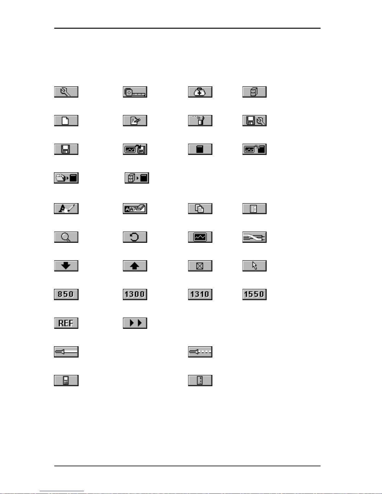
Function Keys
The functions of the 4 keys vary depending on the current display . The
assigned functions are:
Setup Measurements Diagnostics Results
New Edit Delete Save Options
Save Save with Graphs Save to MMC Save with Graphs to MMC
Copy Project to MMC Copy Results to MMC
Erase a letter Clear a field Copy Circuit ID List Circuit IDs
Detail Retest Graph Pair
Next Page Previous Page Select Set Default
Switch to 850nm Switch to 1300nm Switch to 1310nm Switch to 1550nm
Set Reference Continue T est
Switch to Continuous Wave Switch to Modulated (2KHz) Wave
Switch to OMNIScanner Info Switch to OMNIRemote Info
Page 13
1 - 7
OMNIScanner User Guide
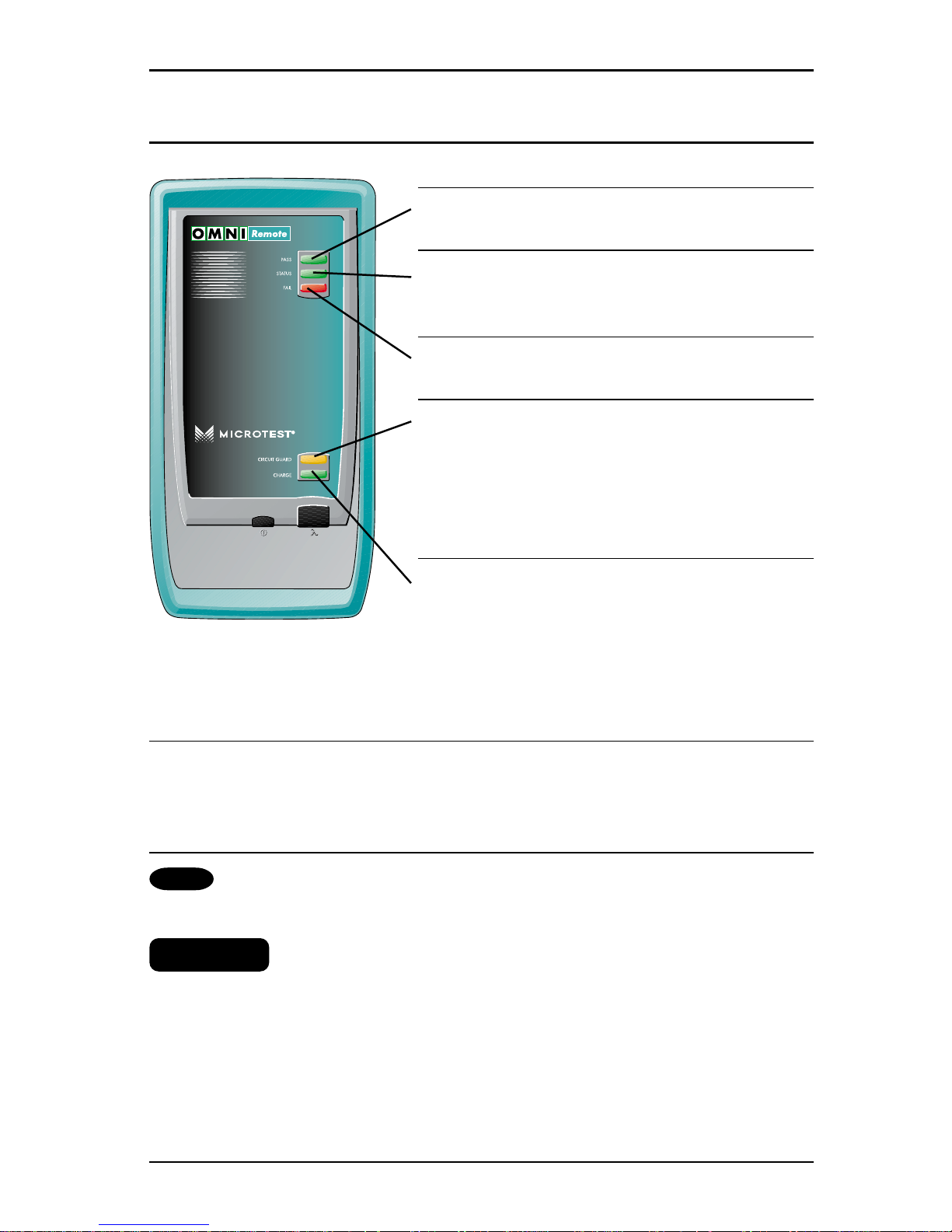
OMNIRemote’s LED Indicators
LED Color Description
PASS Green Overall Autotest Result
is PASS
Status Green (flashing) OMNIRemote is ready
for testing
Green (consistent) OMNIRemote is active
F AIL Red Overall Autotest Result
is FAIL
Circuit Orange Hazard condition is
Guard detected. LED will be lit
in 5 second intervals
until the hazard
condition disappears.
REMOVE CABLE FROM HAZARDOUS SOURCE!
Charge Green OMNIRemote is inactive,
the AC adapter is present,
and the battery pack is
being charged
Green (flashing) OMNIRemote battery is
fully charged
Red (flashing) OMNIRemote battery is low
OMNIRemote Keys
ON/OFF
When turned on OMNIRemote will blink the LEDs.
λ λ
λ λ
λ (Lambda)
When OMNI
Fiber
is attached to OMNI
Remote
, the remote unit can be
used as a light source. With the OMNI
Fiber
adapter attached, press the
λλ
λλ
λ
key to activate the light source and provide continuous or modulated light at
850, 1300, 1310 or 1550 nm. The green LED of the appropriate wavelength
will blink rapidly when modulated light is transmitted. If the transmitted light
is continuous, the green LED will not blink. (See OMNIFiber’s LED indicators in this chapter for further information.)
Page 14
OMNIScanner User Guide
1 - 8
Displaying OMNIScanner and OMNIRemote Results
OMNI
Scanner
and OMNI
Remote
are used together to perform measurements, which allow the scanner to verify installed links or assist in the
diagnosis of physical layer network problems. To accomplish these measurements, OMNI
Scanner
and OMNI
Remote
are connected at either end
of a network-cabling link. The end at which the scanner is connected, is
referred to as the ‘Scanner end’, and the end at which the remote unit is
connected, is referred to as the ‘Remote end’.
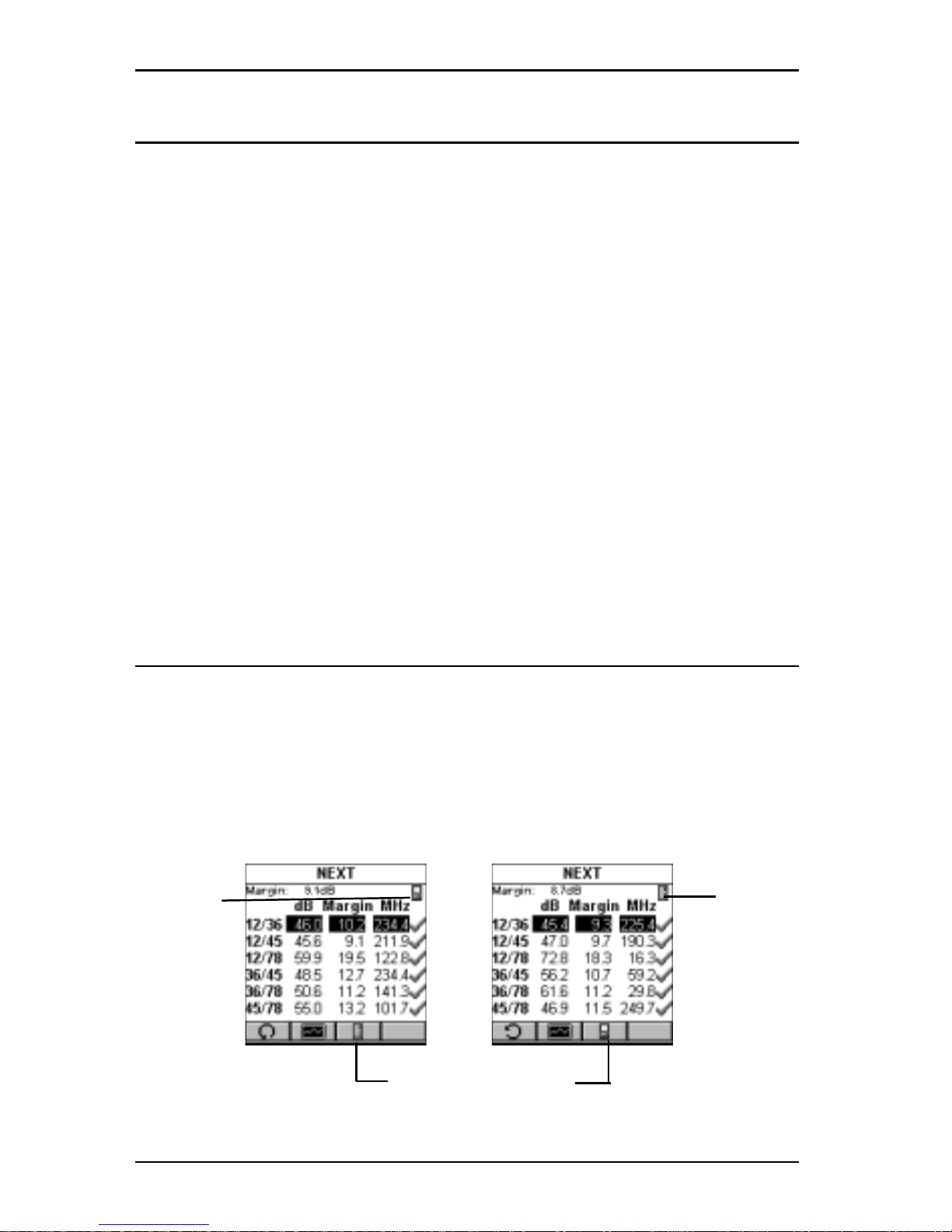
Indicates
OMNI
Scanner
test
results.
Indicates
OMNI
Remote
test
results.
Toggles the display
from Scanner to Remote end
test results.
When T o Use OMNIRemote
Most measurements require the use of OMNI
Remote
at the far end of the
cable. For other measurements, OMNI
Remote
can be connected, but its
use is optional. OMNI
Scanner
detects the presence of the remote unit and
automatically configures it for the measurement to be performed.
Twisted Pair Measurements requiring the use of OMNIRemote:
• Autotest • Return Loss
• Wiremap • ELFEXT and Power Sum ELFEXT
• NEXT and Power Sum NEXT • ACR and Power Sum ACR
• Attenuation
Twisted Pair Measurements not requiring the use of OMNIRemote:
• Length / Delay / Skew • Resistance
COAX Measurements do not require the use of OMNIRemote
Fiber Measurements require the use of OMNIRemote with an OMNIFiber Adapter
Page 15

1 - 9
OMNIScanner User Guide
OMNI
Scanner
displays test results for both ends of the link. Press
or to toggle the display between Scanner and Remote test results.
Note: Refer to the graphics in Chapter 2 - Getting Started: Typical Test
Configurations for instructions on connecting OMNIScanner and OMNI-
Remote for basic link and full channel tests.
Page 16
OMNIScanner User Guide
1 - 10
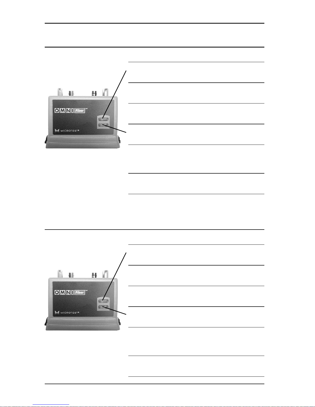
OMNIFiber MM LED Indicators
LED Color Description
850nm Green OMNIFiber is transmitting
at 850 nm
850nm Green (flashing) OMNIFiber is transmitting
modulated light at 850 nm
850nm Orange Part 1 of Two Way test
completed, switch fibers
1300/ Green OMNIFiber is transmitting
1310nm at 1300/1310nm
1300/ Green (flashing) OMNIFiber is transmitting
1310nm modulated light at
1300/1310 nm
1300/ Orange Part 1 of Two Way test
1310nm completed, switch fibers
OMNIFiber SM LED Indicators
LED Color Description
1310nm Green OMNIFiber is transmitting
at 1310 nm
1310nm Green (flashing) OMNIFiber is transmitting
modulated light at 1310 nm
1310nm Orange Part 1 of Two Way test
completed, switch fibers
1550nm Green OMNIFiber is transmitting
at 1550nm
1550nm Green (flashing) OMNIFiber is transmitting
modulated light at 1550 nm
1550nm Orange Part 1 of Two Way test
completed, switch fibers
Page 17
1 - 11
OMNIScanner User Guide
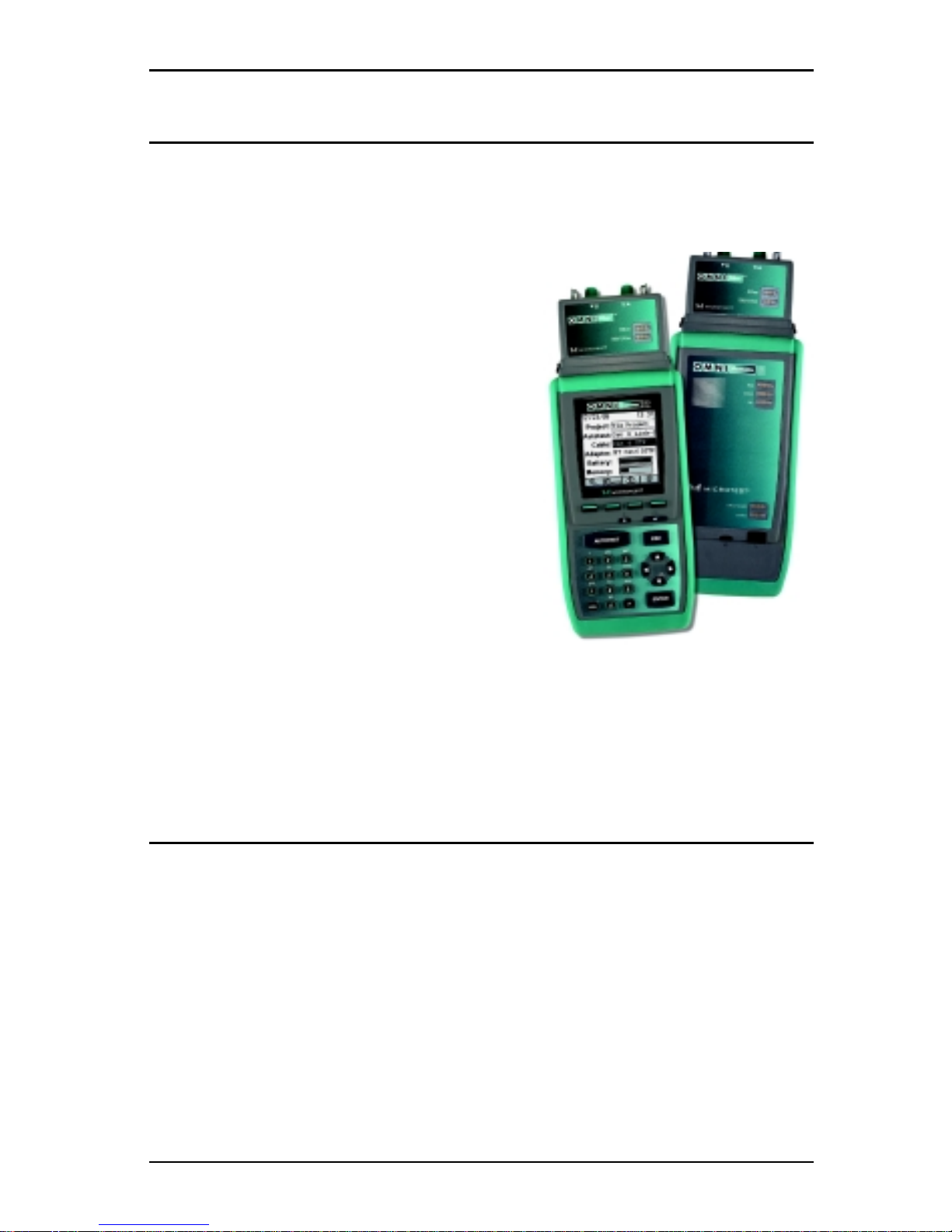
Attaching the OMNIScanner Fiber Adapters
Note: Use dust caps to protect the connectors from dirt. Keep the connectors covered when the Fiber Adapters are not in use. This helps to ensure
that contaminants from handling fiber do not affect test measurements.
Note: Both OMNIFiber adapters have 160
pin connector covers. Keep the 160 pin
connectors covered when the Fiber Adapters are not in use.
T o attach a fiber adapter to OMNI
Scanner
proceed as follows:
1. Remove the 160 pin connector cover from
the OMNI
Fiber
adapter by gently pressing
the black push button latches. The cover
will be released.
2. Push the OMNI
Fiber
adapter onto
OMNI
Scanner’s
160 pin connector until it
snaps into position.
3. T o remove OMNI
Fiber,
use the push
button latches to release the secured adapter.
4. Protect OMNI
Fiber’s
160 pin connector by snapping the cover back in
place.
Attaching the Microtest Connector Adapter
OMNI
Fiber
has one ST-style connector port (TX) and one threaded optical
receiver port (RX) which accepts different Microtest connector adapters.
Attach the included ST connector adapters to the OMNIFiber RX receiver
ports before connecting jumpers.
Note: Keep the connectors covered when the Fiber Adapters are not in use.
Several Microtest connector adapters are available (as optional accessories)
for the OMNI
Fiber
optical receiver port (RX).
Page 18
OMNIScanner User Guide
1 - 12
Editing With OMNIScanner
OMNI
Scanner
includes sophisticated easy-to-use editing methods to
accommodate a variety of user-definable items. Different fields have
different editing procedures. Please follow the described procedures to
make editing with the OMNI
Scanner
effortless.
Note: All editable fields can be easily recognized by their dotted borders.
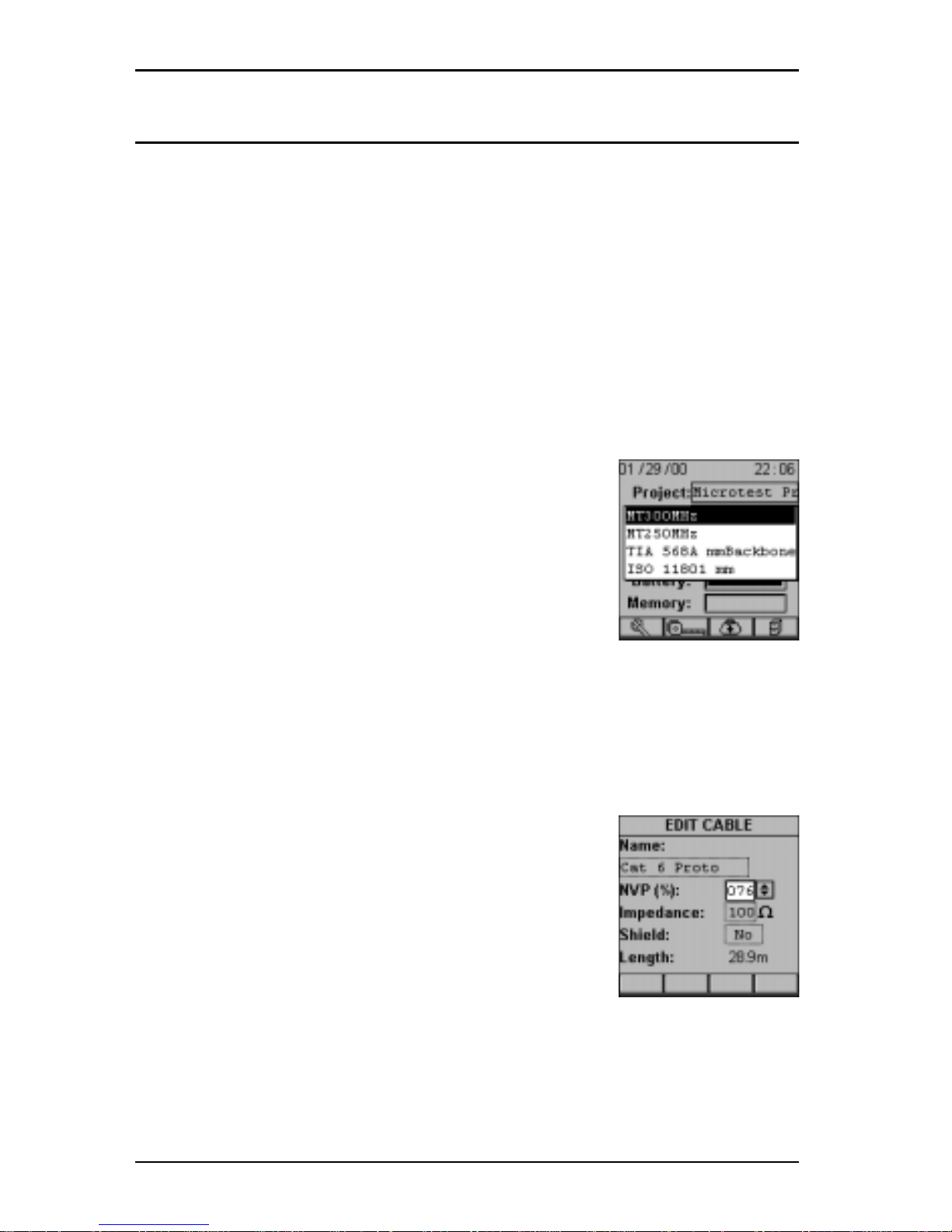
Predefined Lists
To quickly and easily select Projects, Autotests, Cables, etc. OMNI
Scanner
uses predefined lists.
1. Use the é or ê arrow keys to move the cursor to
the field to be edited and press ENTER.
A pop-up list will be displayed while the main screen
becomes inactive.
2. Use the é or ê arrow keys to move the cursor to
the appropriate item or value and press ENTER to
select it as the new default.
Editing Numeric Fields with the Spin Control
1. Use the é or ê arrow keys to move the cursor to the field to be edited.
The entire field will be highlighted in black.
2. Press ENTER. Notice that the field is now highlighted in white and the main screen in the background turns gray to indicate that the edit mode has
been launched.
3. Press the é or ê arrow keys on your keypad to
scroll through the string of numbers.
4. Press ENTER or ESC to accept the value and terminate edit mode.
Page 19
1 - 13
OMNIScanner User Guide
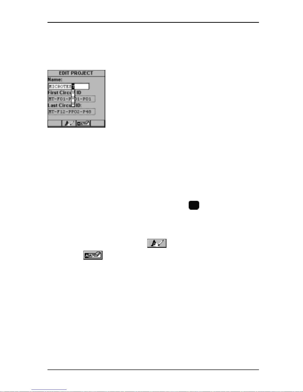
Editing Alphanumeric Fields
T o start the editing procedure for fields that contain alphabetic and numeric
characters use the alphanumeric keypad.
1. Use the é or ê arrow keys to move the cursor to
the field to be edited. The entire field will be highlighted in black.
2. Press ENTER. Notice that the field is now
highlighted in white and the main screen in the
background turns gray to indicate that the edit mode
has been launched. The first letter in the field is
highlighted in black.
3. Press any numerical key on your keypad to display a small drop-down
list containing letters to choose from. Example: Press 8 to choose t, u, v or
the number 8.
Note: Alphabetic and special characters are printed above each numbered
key on the keypad. For example, ABC is printed above the 2 key.
4. Use the é or ê arrow key to move to the appropriate character , or
simply press 8 on your keypad repeatedly until the appropriate letter or
number appears in the highlighted field. Press the
A/a
key to toggle
between uppercase and lowercase letters.
5. Press the è to close the drop-down list and highlight the next letter to be
edited. Notice that OMNI
Scanner
does not overwrite existing characters.
To delete single characters use the function key. To clear an entire
field use the function key.
6. Press ENTER to accept the field and exit the edit mode.
Page 20

OMNIScanner User Guide
1 - 14
T echnical Support
If you have technical questions, you may contact Microtest Technical
Support by phone, fax, or e-mail.
Note: Before calling Technical Support, please have your Serial number,
and the Hardware and Software Version numbers available. See Product
Versions section below.
Americas and Asia Pacific:
1-800-NET-FIXR (1-800-638-3497) (U.S. and Canada only)
1-800-419-8991 (F AX) (U.S. and Canada only)
1-602-952-6494 (F AX)
[email protected] (E-mail)
www .microtest.com/support (W eb Support)
If the 1-800 service is not available, please contact your local authorized
Microtest reseller.
Greater Europe, Middle East, and Africa:
+44 1293 456025 (V oice)
+44 1293 456008 (FAX)
[email protected] (E-mail)
For new product information:
World Wide Web page at http://www.microtest.com
[email protected] (E-mail for U.S.)
[email protected] (E-mail for Europe)
For the latest cable installation, international standards, and conformance techniques:
World Wide Web page at http://www.cabletesting.com
Page 21
1 - 15
OMNIScanner User Guide
Product Versions
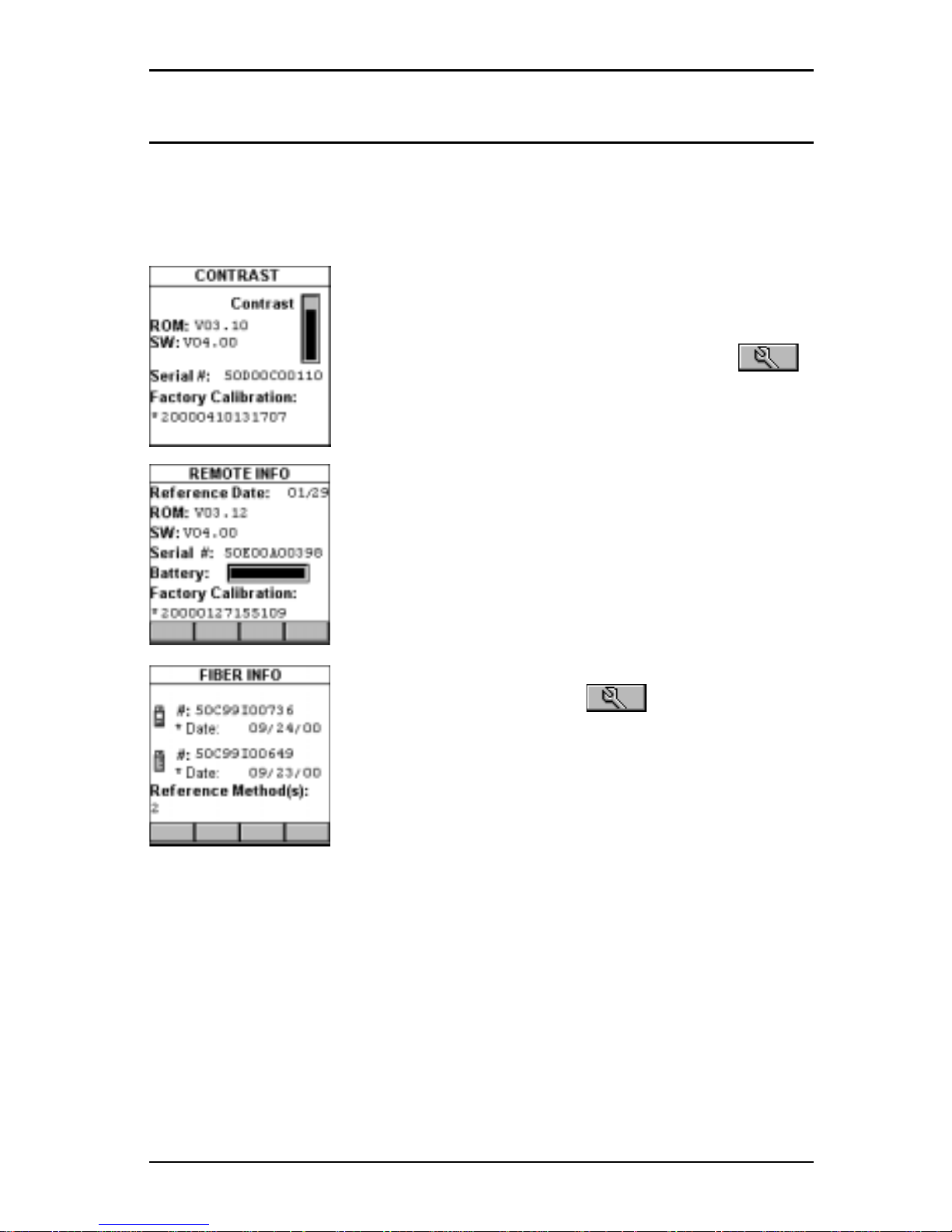
T o display the software version #, the hardware version #, the serial #, and
the factory calibration data for OMNI
Scanner,
press and hold the Backlight
key . The CONTRAST screen will be displayed, which contains information
that you may need to provide when calling T echnical Support.
T o display software, hardware and serial number
information for OMNI
Remote,
connect the units with
the supplied Link Adapter and the Channel -, Mod 8 -,
or Set Reference Adapter and then press the
(Setup) function key .
Select Remote Info to open the REMOTE INFO
screen, which contains the date the reference was
last set, the hardware and software information, the
serial number , the battery indicator , and the factory
calibration data.
The serial number can also be found on the back of
each unit.
T o display information for OMNI
Fiber,
attach the
OMNI
Fiber
adapters to OMNI
Scanner
and OMNI-
Remote
, connect the units with the supplied fiber
launch cable and press the (Setup) function
key.
Select Fiber Info to open the FIBER INFO screen,
which contains the serial numbers, the date the
adapters were last factory calibrated, and the current
reference method.
Page 22

OMNIScanner User Guide
1 - 16
Page 23
2 - 1
OMNIScanner User Guide
Chapter 2 - Getting Started
Twisted Pair Networks
Charging OMNIScanner’s Battery
In order to operate the OMNI
Scanner
and OMNI
Remote
with battery
power , the battery must first be charged. Until the charging cycle is complete, the units can run with the AC adapter plugged in.
(See Appendix B -
Batteries for more information about the batteries.)
OMNIScanner’s Project Screen
OMNI
Scanner
’s project screen is designed to allow you to perform all
typical work flow operations. The project, the test specifications, and the
cable types are all selectable from the OMNI
Scanner
Project screen.
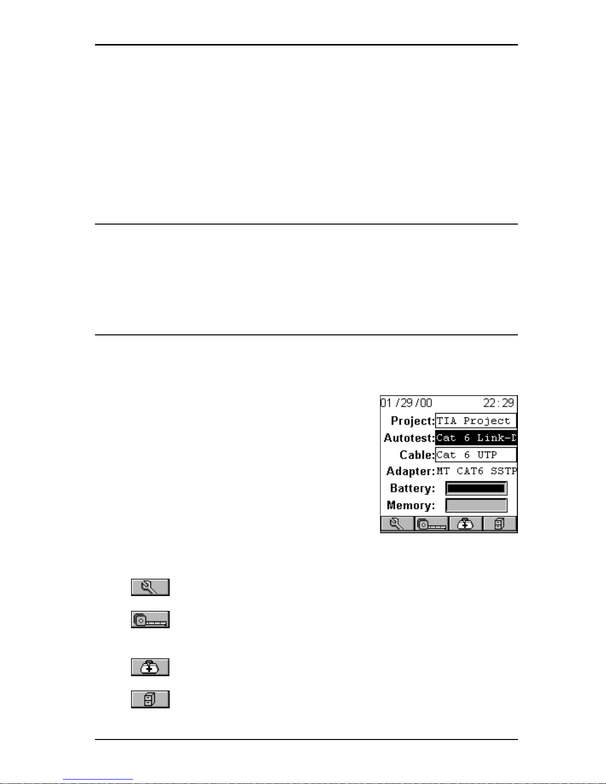
Press the ON/OFF key to power the unit on and
display the Project screen with its three user
definable items: Project, Autotest, and Cable.
The Project name will be highlighted. Use the ê
to move the highlight to the Autotest or Cable
field. Press ENTER when a field is highlighted to
change the current Project, Autotest, or Cable.
OMNI
Scanner
will auto-sense the Adapter.
Battery and Memory status are graphically indicated by gauges with a
display ranging from empty (left hand side) to full (right hand side).
Press (Setup) to select Autotests, configure Cables, and more.
Press (Measurements) to measure a cable’s performance, utilizing
a variety of tests.
Press (Diagnostics) to identify network cabling faults
Press (Results) to view and manage stored test results.
Page 24

OMNIScanner User Guide
2 - 2
Certification of Network Installations
OMNI
Scanner
is designed to efficiently certify cabling installations through
its Autotest feature. Test results, test specifications, and cable types are
organized into Projects. The Project, its test specifications and cable types
are selectable from the OMNI
Scanner
Project screen.
OMNI
Scanner
contains a number of predefined projects, grouped by test
standards, to allow easy and fast operation.
The typical order of operations performed when certifying a cable installation is as follows:
Preparation
Prior to initial certification, perform the following:
1. Run a self-test by setting the reference for OMNI
Scanner
and OMNI-
Remote periodically , e.g. weekly .
2. Select the appropriate Project, Autotest specification, and Cable type.
Certification
Perform the following for each installed cable to be tested:
3. Attach OMNI
Scanner
to one end of the link, which is typically at the
patch panel in a wiring closet.
4. Attach OMNI
Remote
to the corresponding outlet at the other end of the
cable link.
5. Run Autotest.
6. Save test results.
Completion
At the end of the day or shift, the test results are uploaded using
Scanlink
Tools
software.
Scanlink Tools
support the following:
• Upload test results
• Storage of test results to files (Scanlink proprietary format)
• Print test reports
• Export results in CSV format
• Setup Projects
• View Graphs
• Edit Autotest information
Page 25
2 - 3
OMNIScanner User Guide
The following sections provide detail on the certification process.
Setting the Reference
A reference must be set when OMNI
Scanner
and OMNI
Remote
are used
as a set for the first time. After the initial reference setting, the process
should be repeated periodically to ensure unit verification. OMNI
Scanner
stores reference data for up to 5 remote units by serial number.
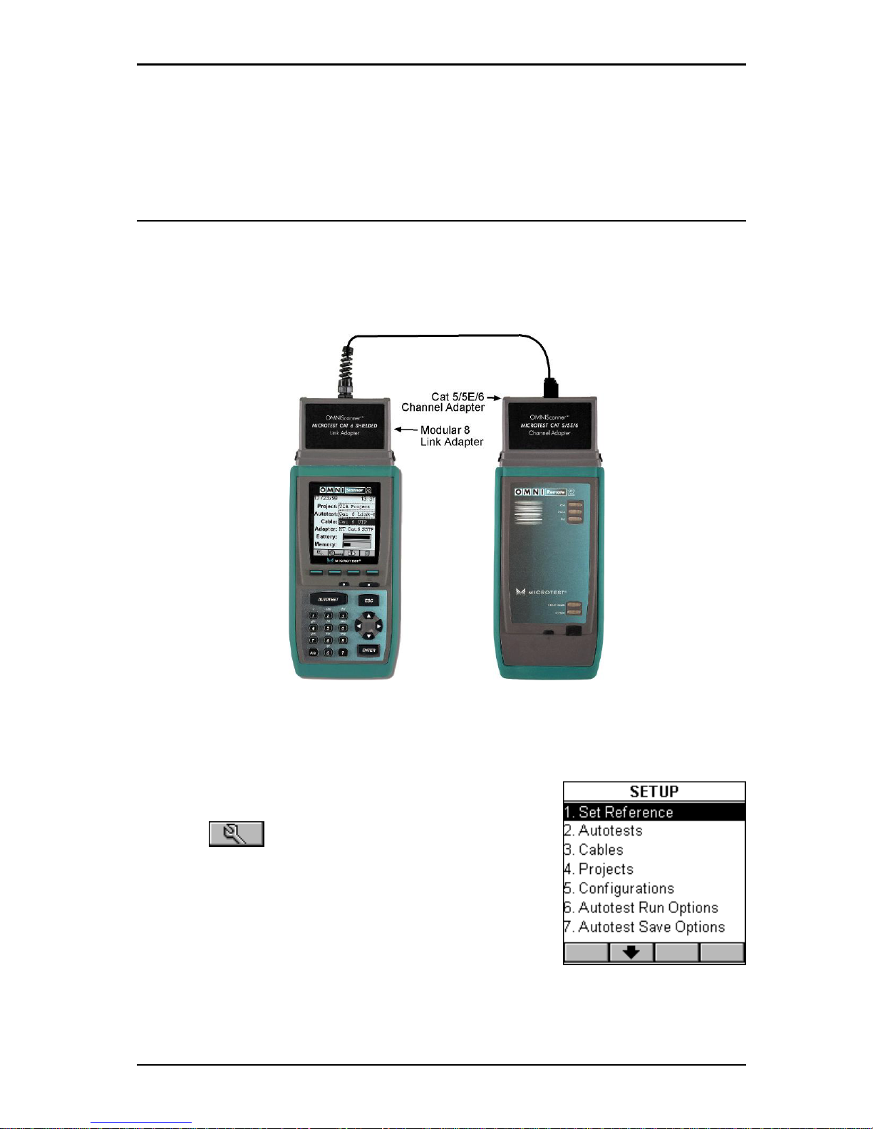
1. To set the reference, connect OMNI
Scanner
and OMNI
Remote
using the
Link Adapter and Channel Adapter* supplied with the scanner (as shown).
*Use the Set Reference Adapter with OMNIScanner L T.
2. Turn OMNI
Scanner
on.
3. Press (Setup).
4. Select Set Reference.
5. On finding OMNI
Remote
, the scanner reports:
Acquiring Reference Data. A gauge will indicate
the progress.
6. Once the reference values has been recorded, OMNI
Scanner
displays
the REMOTE INFO screen.
7. Press ESC to return to OMNI
Scanner
’s SETUP screen.
Page 26
OMNIScanner User Guide
2 - 4
Project Selection
A project name must be selected for test result management. Autotests
and Cables were previously assigned to a specific project through the use
of the OMNI
Scanner
Configuration utility .
(See Chapter 9 - Uploading and
Printing for further information about OMNIScanner Configuration.)
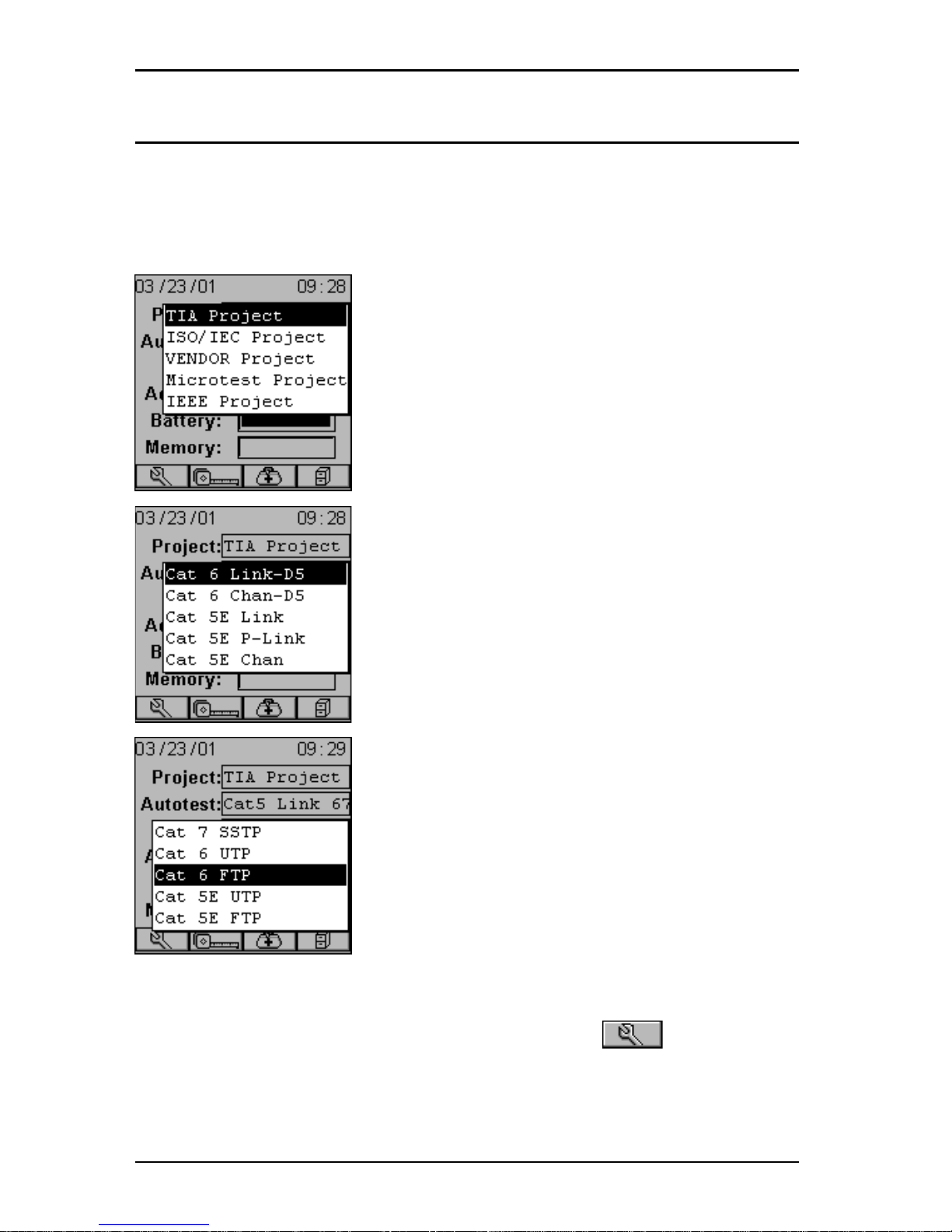
The Project feature is very useful for grouping
test results and eases uploading and sorting of
Autotests stored in the scanner .
1. Use the é or ê to highlight Project: and
press ENTER.
2. Select the appropriate Project from the popup list and press ENTER.
3. Use the é or ê to highlight Autotest: and
press ENTER.
4. Select the appropriate Autotest from the popup list and press ENTER.
5. Use the é or ê to highlight Cable: and press
ENTER.
6. Select the cable type to be tested from the
pop-up list and press ENTER.
OMNIScanner auto-senses the adapter and the
Adapter: field changes to reflect the adapter
that is currently attached. If the adapter is
changed, OMNIScanner will automatically adjust
the content in the fields Autotest: and Cable: to
reflect the new setup.
Every Project has certain Autotests and cables assigned already . These
associated lists will appear in the pop-up lists for each item. If the Autotest
or Cable you want to use is not in a pop-up list, open (Setup) to
select the appropriate item.
(See Chapter 4 - Setup: Autotest, Cable, or
Project for further information.)
Page 27
2 - 5
OMNIScanner User Guide
Running an Autotest for Twisted Pair Cabling
1. Connect OMNI
Scanner
to the near end of the
twisted pair cable you are testing and connect
OMNI
Remote
to the far end.
(See the Typical
Test Configurations for T wisted Pair Cabling
section in this chapter for more information.)
2. Press the
AUTO TEST
key. When testing
twisted pair cable, OMNI
Scanner
will immediately
verify that OMNI
Remote
is attached. If OMNI
Re-
mote
is not attached, OMNI
Scanner
will wait until
it is attached before running the Autotest.
3. Press ESC at any time to cancel the Autotest.
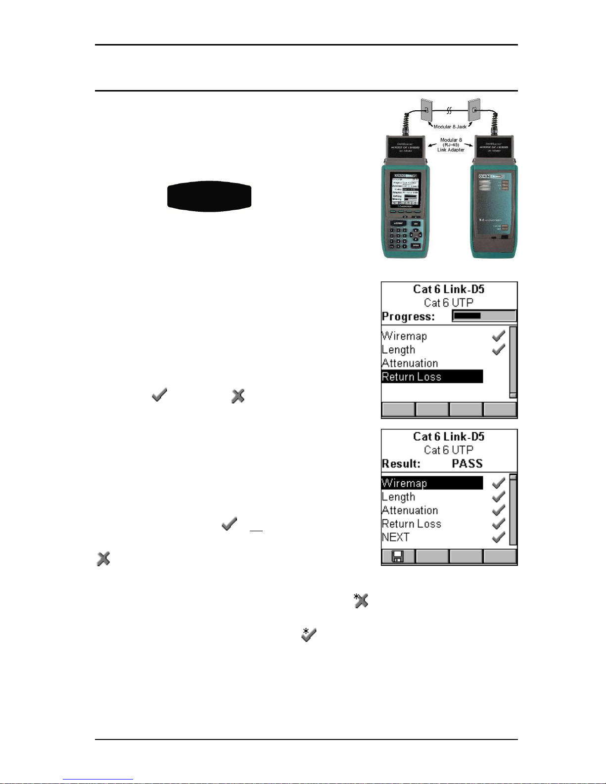
4. The AUTOTEST screen is displayed while
Autotest is running.
The Autotest and the Cable name are displayed
at the top of the screen. A gauge indicates the
test progress. Tests will be listed with their
individual (P ASS) or (FAIL) results as soon
as a test is completed.
Once all tests are performed, the overall test
Result: is displayed as PASS or FAIL.
Note: The list of tests varies depending on the
kind of Autotest that was performed.
An Autotest will P ASS if all the selected tests
met the specified criteria. An Autotest will F AIL
if one or more of the selected tests failed.
If the measured result fails by an amount less than or equal to the accuracy
of the OMNIScanner measurement system, a (marginal FAIL) will be
reported. If the measured result passes by an amount less than or equal to
the accuracy of the measurement, a (marginal P ASS) will be reported.
Marginal results are very close to the P ASS/FAIL line and are within the
accuracy of the measurement for that type of link. Accuracy varies depending upon several conditions including the type of link model and the measurement being performed. In most cases this uncertainty zone is much
less than 1 dB.
Page 28
OMNIScanner User Guide
2 - 6
Saving Twisted Pair Autotest Results
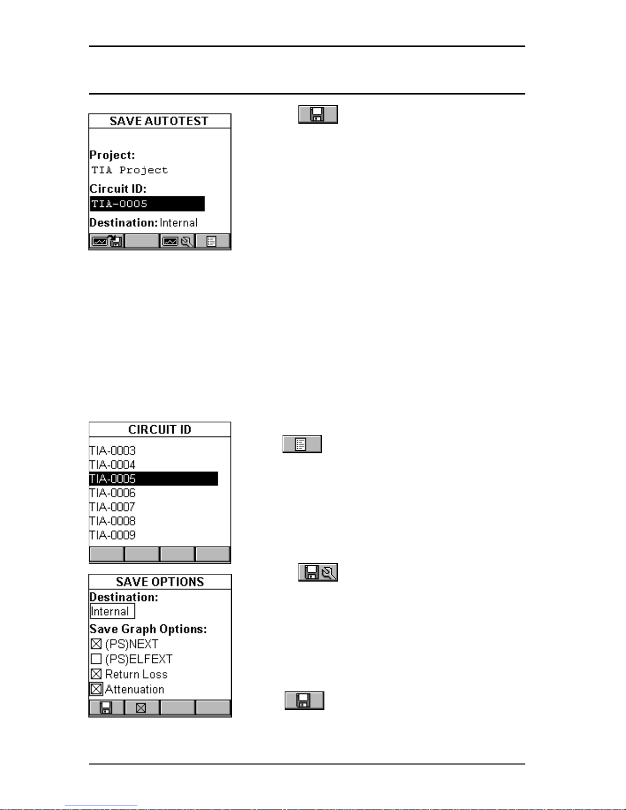
1. Press (Save) from the AUTOTEST
screen to open the SAVE AUTOTEST screen,
where the Autotests can be stored into
OMNI
Scanner
’s memory.
2. The Project: field contains the name of the
project.
3. To assign a unique name to the Autotest,
enter a Circuit ID into the Circuit ID: field.
Circuit IDs can be setup to automatically increment.
(See Chapter 4 -
Setup: Projects: Editing a Circuit ID for further information.)
If an incrementing Circuit ID was created in the PROJECT Setup screen,
the Circuit ID: field will already contain the next available Circuit ID that
can be used as a default.
4. To change the name using OMNI
Scanner
’s edit feature, highlight the
field, and press ENTER to initiate the editing mode.
(See Chapter 1 -
Introduction: Editing with OMNIScanner for more information.)
5. To change the Name using the list function,
press (List). The CIRCUIT ID screen
opens and displays all Circuit IDs available for
the project. Use the ç or è to quickly scroll
through the pages. Use the é or ê to highlight
a Circuit ID and press ENTER to select it as the
name for the Autotest to be saved and return to
the SAVE AUTOTEST screen.
6. Press (Autotest Save Options) to
open the SAVE OPTIONS screen. OMNI-
Scanner
2: Select the Destination for saved
test results (MMC or Internal) and select or
unselect the graphs to be saved.
(See Chapter
4 - Setup: Autotest Save Options for more
information.)
Press (Save) to save the settings and
return to the SAVE AUTOTEST Screen
7. The SA VE AUT OTEST screen’s save function key indicates the
Page 29
2 - 7
OMNIScanner User Guide
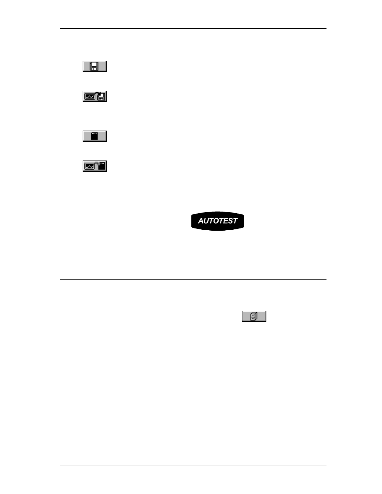
selected Save Option.
Press (Save) to save the test results to OMNI
Scanner’s
internal
memory.
Press (Save with Graphs) to save the test results with their graphs
to OMNI
Scanner’s
internal memory .
Note: Saving graphs will reduce the
number of Autotests that can be stored.
Press
(Save to MMC) to save the test results to the
MultiMediaCard. (OMNI
Scanner2
only .)
Press (Save with Graphs to MMC) to save the test results with their
graphs to the MultiMediaCard. (OMNI
Scanner2
only.)
Note: Saving graphs
will reduce the number of Autotests that can be stored.
8. Press ESC to return to the Autotest screen without saving the Autotest.
9. To run the next Autotest press the key .
Viewing Twisted Pair Autotest Results
This viewing option is only available immediately after the Autotest was
performed.
To view stored test results at a later time, press the (Results)
function key located in the Project screen.
(See Chapter 7 - Results for
more information.)
Note: The list of tests varies depending on the kind of Autotest that was
performed.
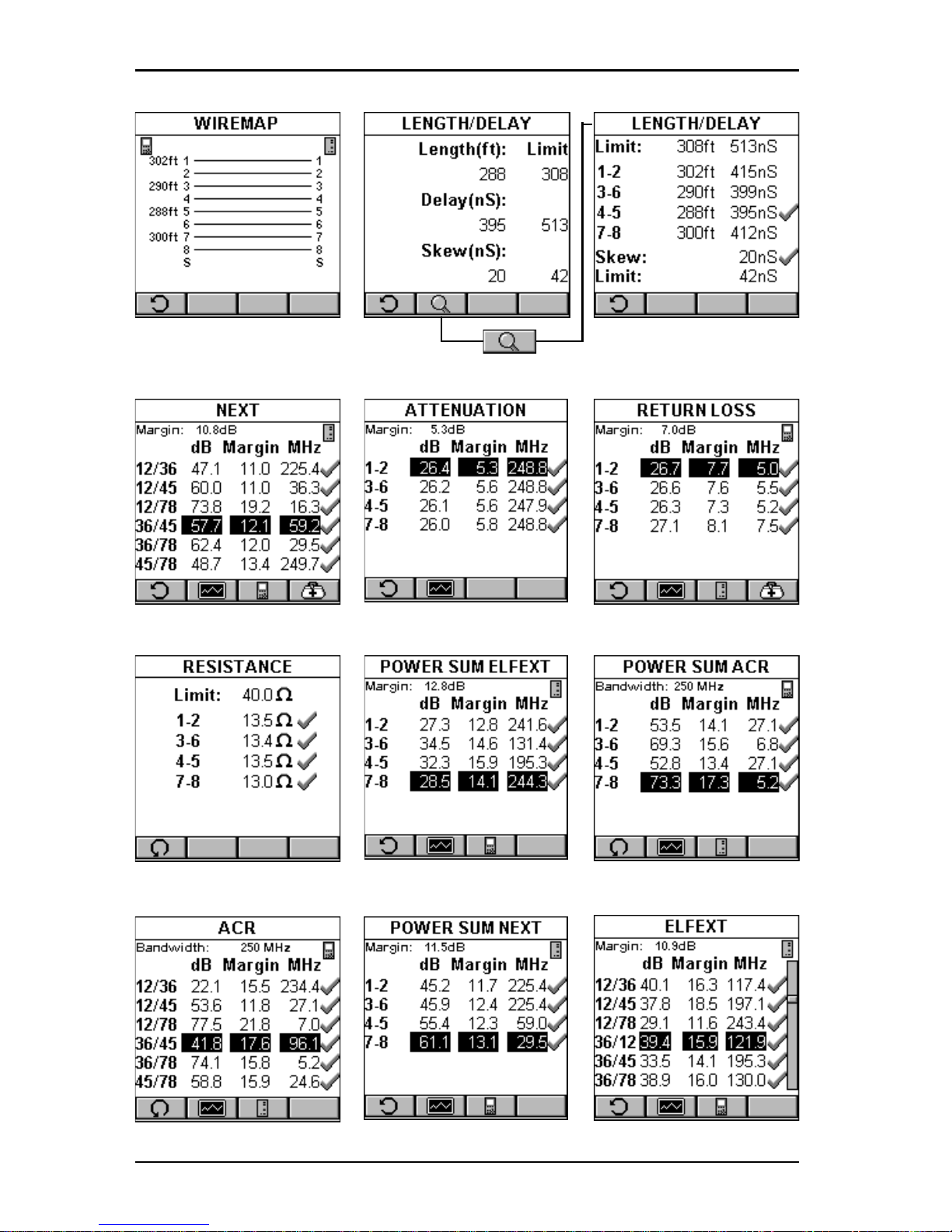
1. To view detailed results of all the tests that were performed during
Autotest, highlight a specific test in the Autotest screen using the é or ê
and press ENTER.
2. Use the ç or è to quickly browse through all other detailed test result
screens and their results.
All Tests that can run during Autotest are displayed on the next page.
(See
Chapter 5 - Measurements for detailed descriptions of each available test.)
Page 30
OMNIScanner User Guide
2 - 8
Page 31
2 - 9
OMNIScanner User Guide
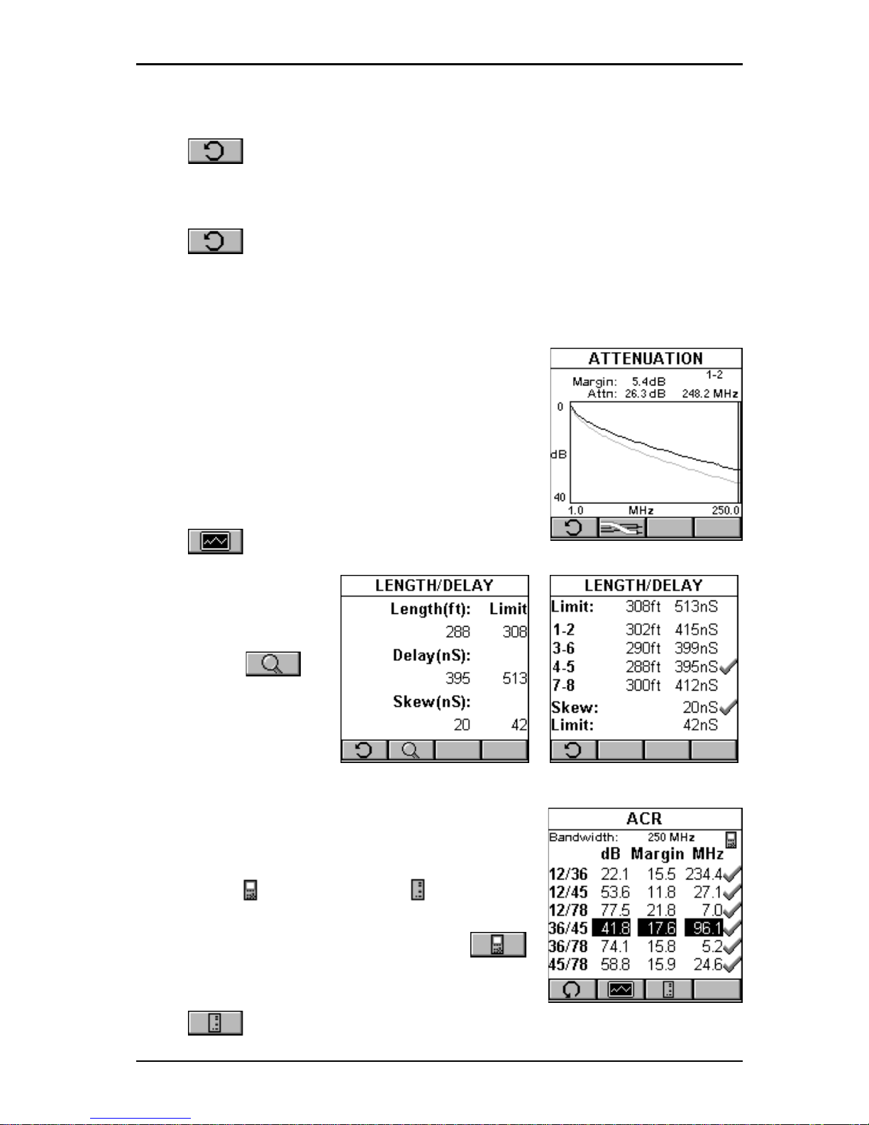
Most Autotest result screens have a retest feature for diagnostic purposes.
Press (Retest) to run continuous tests for the same cable. The
arrow located on the Retest button will be turning for the duration of the
test.
Press (Retest) once more to stop the continuous measurement.
OMNI
Scanner
will display the last measured data.
Note: Retest invalidates an Autotest. After using the retest feature, the
Autotest must be repeated before results can be saved.
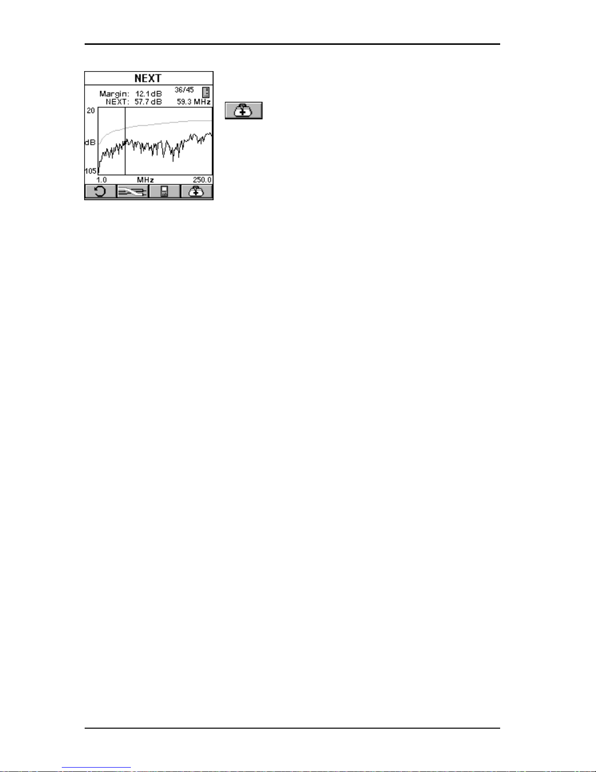
The NEXT, Attenuation, Return Loss, Power Sum
NEXT, ELFEXT, ACR, Power Sum ELFEXT, and
Power Sum ACR test result screens have a graph
feature to display the graph associated with the
test. To avoid misinterpretation, the limit line is
shown in a gray color , while the actual measurement is represented in black.
Press (Graph) to display a graph for a pair
or a pair combination.
The Length results
screen has a
(Detail) function key
that allows you to view
detailed test results for
each pair .
Tests that require the use of OMNI
Remote
will
have small icons in the upper right corner of the
titlebar to indicate whether the information is
pertinent for OMNI
Scanner
or OMNI
Re-
mote
.
To toggle between the two screens press
to open the screen that contains the information
for OMNI
Scanner.
Press to display the information for OMNI
Remote
.
Page 32
OMNIScanner User Guide
2 - 10
The RETURN LOSS and NEXT screens have
(Diagnostic) function keys to help you with
the interpretation of failed test results.
(See
Chapter 6 - TDRL and TDNXT for detailed
information.)
Page 33
2 - 11
OMNIScanner User Guide
Typical Test Configurations for Twisted Pair Cabling
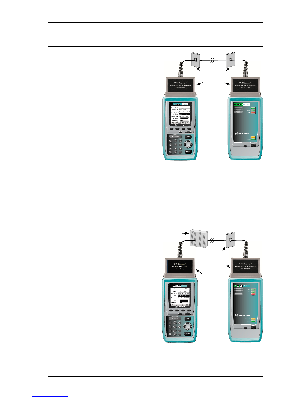
Basic Link
The graphic shows the connection of
OMNI
Scanner
to a Modular 8 Jack in
the wiring closet, and OMNI
Remote
to a Modular 8 jack in the work area.
Use the supplied MICROTEST Link
Adapters at both ends of the link to
attach OMNI
Scanner
and OMNI-
Remote
to the Modular 8 jacks.
Basic Link with 110 Block and Modular 8 Jack
The graphic shows the connection of OMNI
Scanner
to an IDC (110) block
in the wiring closet, and OMNI
Remote
to a Modular 8 jack in the work area.
The Punch Down Block Adapter kits
MICROTEST 1 10 A Link Adapter
and MICROTEST 110 B Link
Adapter are available (as optional
accessories) to interface the OMNI-
Scanner
and OMNI
Remote
with IDC
(1 10) punch-down blocks.
Use the MICROTEST 1 10 A or B
Link Adapter to attach OMNI-
Scanner
to the 1 10 Punch Down
block. At the other end of the link,
use the MICROTEST Link Adapter
to attach OMNI
Remote
to the
Modular 8 jack.
Modular 8
(RJ-45)
Link Adapter
Modular 8 Jack
Modular 8
Link Adapter
Modular 8 Jack
110 Block
110 A
Link Adapter
Page 34
OMNIScanner User Guide
2 - 12
Full Channel with Modular 8 Jacks
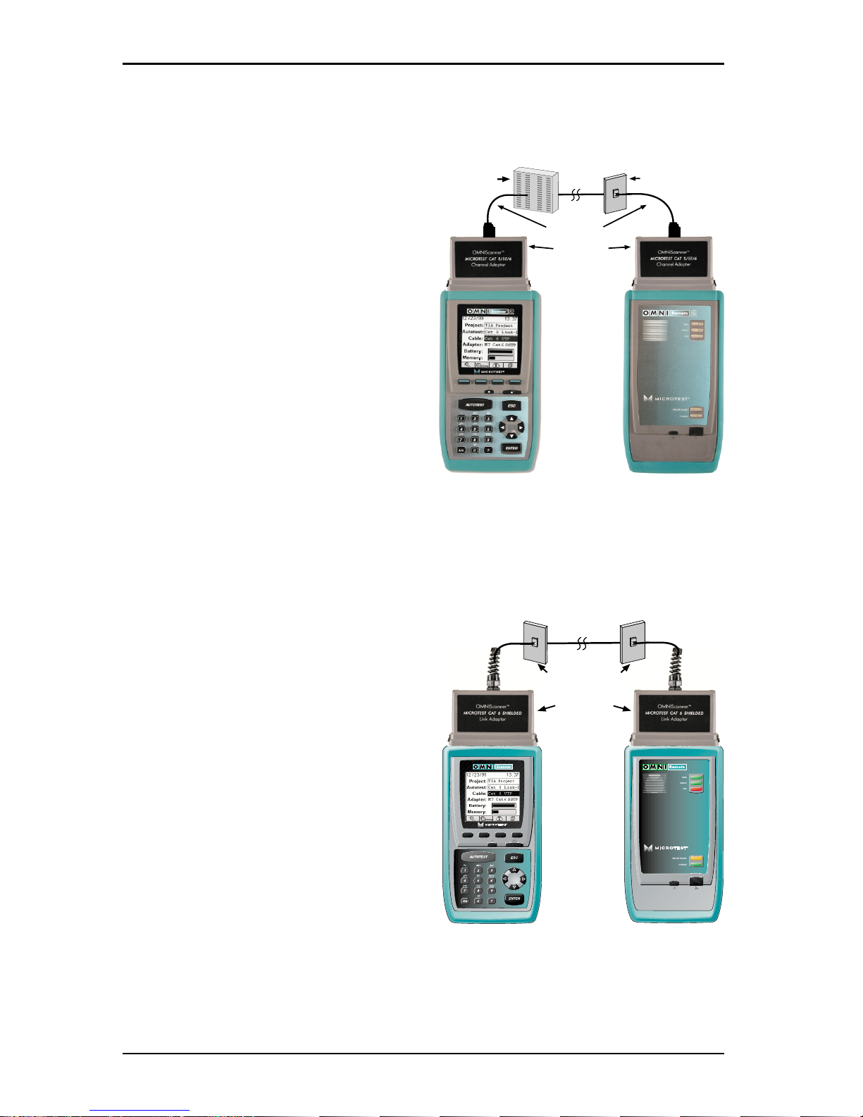
A Full Channel consists of all the link elements from the hub to the workstation.
For cables terminated with a modular 8 plug, use the supplied modular
8 MICROTEST Channel Adapter*
and attach OMNI
Scanner
and
OMNI
Remote
to the channel patch
cords.
*MICROTEST Channel Adapters
are available as optional accessories
for OMNIScanner LT.
Note: Best results for Category 6
channel tests will be optained when
using OMNIScanner software
version 4.0 or higher, which utilizes
A VC (Adaptive Vector CancellationTM).
Permanent Link
For Permanent Link Autotests,
connect the supplied Link adapters in
the same manner as the Basic Link.
During permanent link Autotests, the
effects of the link adapters are
removed from the measurements.
The Permanent Link method measures the link only, from jack to jack
(including the Modular 8 plug that
plugs into the Jack).
Note: Best results for Category 6
channel tests will be optained when
using OMNIScanner software
version 4.0 or higher.
For more information on the Permanent Link, the Basic Link, and the
Channel, please visit www.cabletesting.com.
Cat 5/5E/6
Channel Adapter
Modular 8
Jack
110 Block
User Cable
Modular 8
(RJ-45)
Link Adapter
Modular 8 Jack
Page 35
3 - 1
OMNIScanner User Guide
Chapter 3 - Getting Started
Fiber Optic Networks
Charging OMNIScanner’s Battery
In order to operate the OMNI
Scanner
and OMNI
Remote
with battery power ,
the battery must first be charged. Until the charging cycle is complete, the
units can run with the AC adapter plugged in.
(See Appendix B - Batteries
for more information about the batteries.)
OMNIScanner’s Project Screen
The Project screen is designed to allow you to perform all typical work flow
operations. The Project, the test specifications, and the cable types are all
selectable from the Project screen.
Press the ON/OFF key to power the unit on and display the project screen
with its three user definable items: Project, Autotest, and Cable.
The Project name will be highlighted. Use the
ê to move the highlight to the Autotest cur-
rently selected. Use the ê to highlight the
currently selected Cable type. OMNI
Scanner
will auto-sense the Adapter.
Battery and Memory status are graphically
indicated by gauges with a display ranging from
empty (left hand side) to full (right hand side).
Press (Setup) to select Autotests, configure Cables and Projects,
view OMNIFiber information, edit User Options, and more.
Press (Measurements) to measure a cable’s performance, utilizing
a variety of tests.
Press (Results) to view and manage stored test results.
Page 36

OMNIScanner User Guide
3 - 2
Certification of Fiber Installations
OMNI
Scanner
and OMNI
Fiber
are designed to efficiently certify fiber optic
cabling installations through the Autotest feature. Test results, test specifications, and cable types are organized into Projects. The Project, its test
specifications and cable types are selectable from the OMNI
Scanner
Project screen.
OMNI
Scanner
contains a number a predefined projects, grouped by test
standards, to allow easy and fast operation.
The typical order of operations performed when certifying a cable installa-
tion is as follows:
Preparation
Prior to initial certification, perform the following:
1. Attach an OMNI
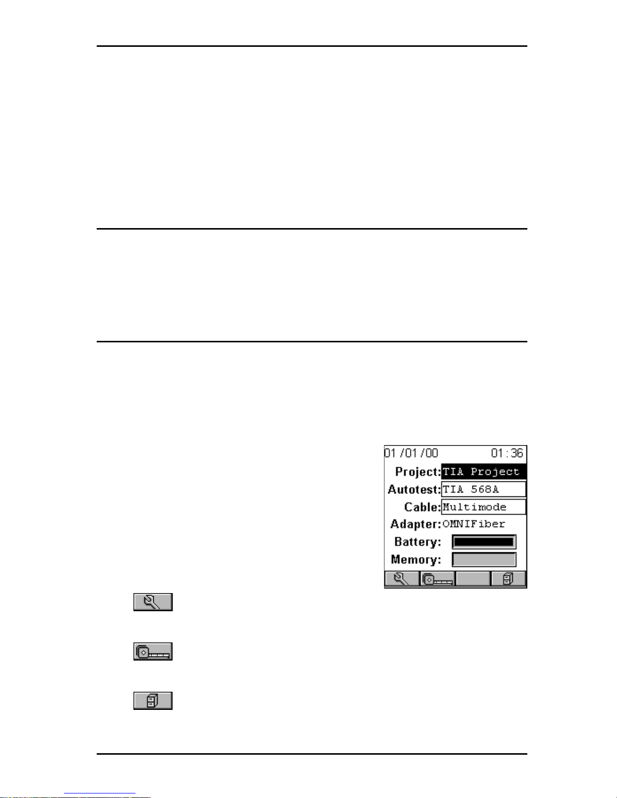
Fiber
to OMNI
Scanner
. This will be referred to as the
OMNI
Fiber
Main.
2. Attach an OMNI
Fiber
to OMNIRemote. This will be referred to as the
OMNI
Fiber
Remote.
3. Establish a reference power by setting the reference.
4. Select the appropriate Project, Autotest specification, and Cable type.
Certification
Perform the following for each installed fiber to be tested:
5. Attach OMNI
Fiber
Main to one end of the link, which is typically at the
patch panel in a wiring closet.
6. Attach OMNI
Fiber
Remote to the corresponding patch panel or outlet at
the other end of the cable link.
7. Run Autotest.
8. Save test results.
Completion
At the end of the day or shift, the test results are uploaded using
Scanlink
Tools
software.
Page 37
3 - 3
OMNIScanner User Guide
Scanlink Tools
support the following:
• Upload test results
• Storage of test results to files (Scanlink proprietary format)
• Print test reports
• Export results in CSV format
• Setup Projects
• Edit Autotest Information
Setting the Reference for Fiber Optic Cabling
Note: To ensure consistent accurate measurements, the reference value
must be set each time the connector adapter or the test configuration is
changed. Since the reference value expires each day at midnight, a reference must be established least once each calendar day that the OMNIFiber is used.
1. Attach the Microtest connector adapters to each
of the OMNIFiber RX ports.
2. T o set the reference value, connect the OMNI-
Fiber
Main and OMNI
Fiber
Remote using launch
cables (jumpers) and couplers.
See Chapter 8 Fiber Optic Reference Methods for further information.
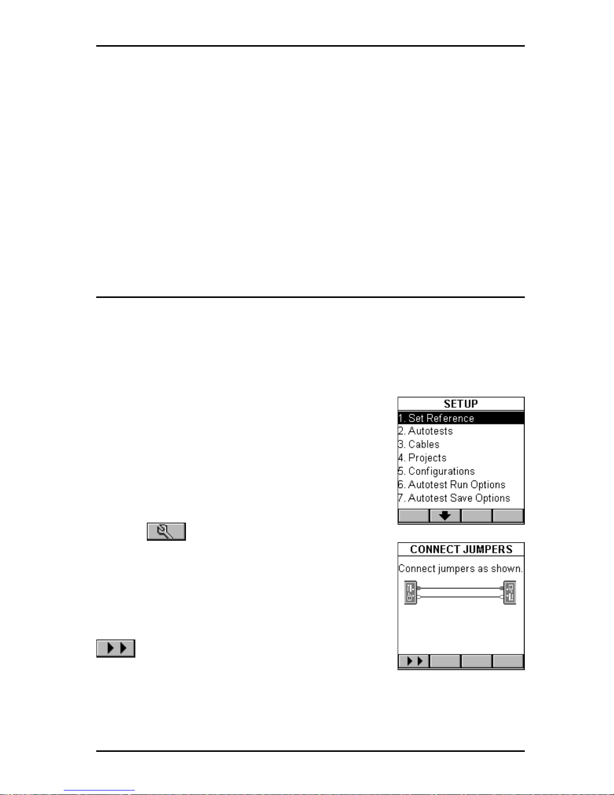
3. Press (Setup) and then select Set
Reference.
4. The CONNECT JUMPERS screen will display
how the jumpers need to be connected so that the
reference value can be recorded.
5. Connect the jumpers as shown and press
(Continue) to collect the reference data
while the SET REFERENCE screen is displayed.
OMNI
Scanner
will store a separate reference value for each wavelength.
OMNI
Scanner
will store reference data for up to 5 OMNI
Fiber
pairs.
Note: Once the reference value has been set, ensure that both launch
Page 38
OMNIScanner User Guide
3 - 4
cables remain attached to the fiber adapters’ TX
(transmit) ports so that the connections are not
disturbed.
6. Once the reference value has been set, OMNI-
Scanner
will display the FIBER INFO screen.
7. Press ESC to return to the SETUP screen.
Project Selection
A project name must be selected for test result management. Autotests and
Cables were previously assigned to a specific project through the use of the
OMNI
Scanner
Configuration software.
(See Chapter 9 - Uploading and
Printing for further information about OMNIScanner Configuration.)
The Project feature is very useful for grouping test
results and eases uploading and sorting of
Autotests stored in the scanner.
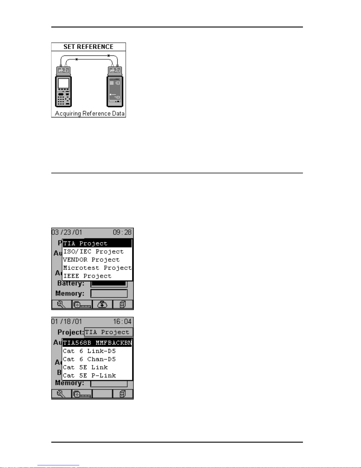
1. Use the é or ê to highlight Project: and
press ENTER.
2. Select the appropriate Project from the pop-up
list and press ENTER.
3. Use the é or ê to highlight Autotest: and
press ENTER. Note: Different Autotests have
different reference methods already assigned to
them.
4. Select the appropriate Autotest from the popup list and press ENTER.
5. Use the é or ê to highlight Cable: and press
ENTER.
6. Select the cable type to be tested from the pop-up list and press ENTER.
Page 39
3 - 5
OMNIScanner User Guide
The Adapter: field will automatically change to
reflect that OMNI
Fiber
is currently attached.
OMNI
Scanner
auto-senses the adapter . If the
adapter is changed, OMNI
Scanner
will automatically adjust the content in the fields Autotest:
and Cable: to reflect the new setup.
Every Project has certain Autotests and cables
assigned already . These associated lists will
appear in the pop-up lists for each item. If the
Autotest or Cable you want to use is not in a pop-up list, open
(Setup) to select the appropriate item.
(See Chapter 4 - Setup: Autotest,
Cable, or Project for further information.)
Running an Autotest for Fiber Optic Cabling
Preparing an Autotest
1. Connect OMNI
Fiber
Main to the near end of the RX/TX fiber pair you are
testing and connect OMNI
Fiber
Remote to the far end. Depending on the
method that was used to obtain the reference, connect your fibers as
follows:
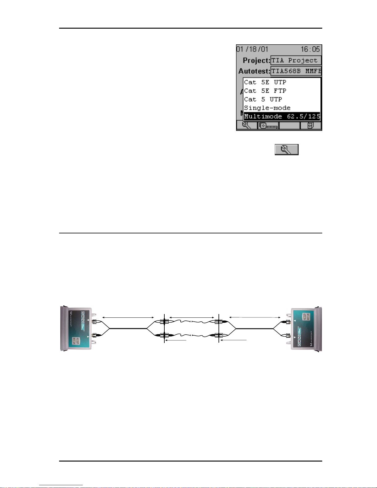
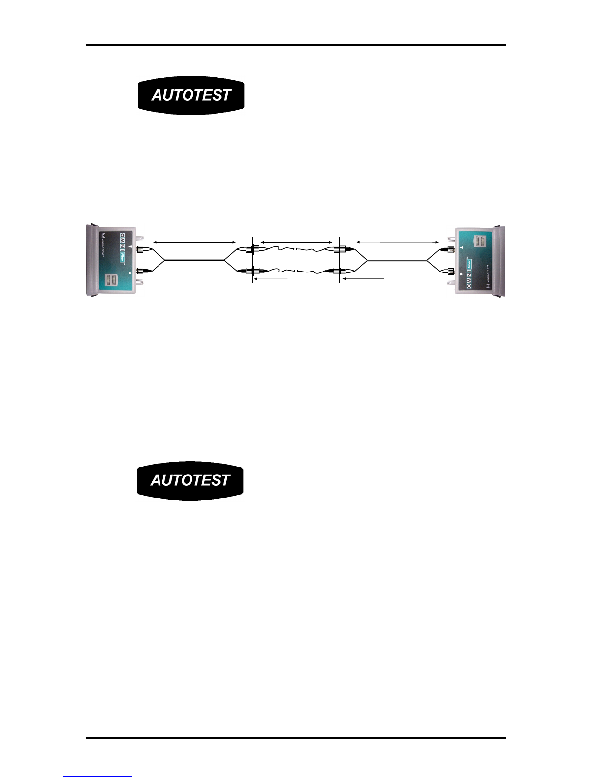
2 JUMPER METHOD AUTOTEST
T o run an Autotest when the 2-Jumper Method was used to set the Reference proceed as follows:
1. Do not disconnect the launch cables from the OMNI
Fiber
.
2. Remove the connector sleeves that connect the two launch cables.
3. Connect the OMNI
Fiber
Main to one end of the duplex link under test,
and the OMNI
Fiber
Remote to the opposite end.
RX
TX
850 nm
1300/1310 nm
RX
TX
850 nm
1300/1310 nm
2 m Launch Cable
2 m Launch Cable
Patch Panel
Wall Plate
Cable under Test
Page 40
OMNIScanner User Guide
3 - 6
4. Press .
1 JUMPER METHOD AUTOTEST
T o run an Autotest when the 1-Jumper Method was used to set the Reference proceed as follows:
1. Do not disconnect the black connectors which are attached to the TX port
of the OMNI
Fiber
.
2. Disconnect the black connectors that are attached to the RX ports of the
OMNI
Fiber
.
3. Connect the white connectors to the RX ports on the OMNI
Fiber.
4. Connect the OMNI
Fiber
Main to one end of the duplex link under test
and the OMNI
Fiber
Remote to the opposite end.
5. Press .
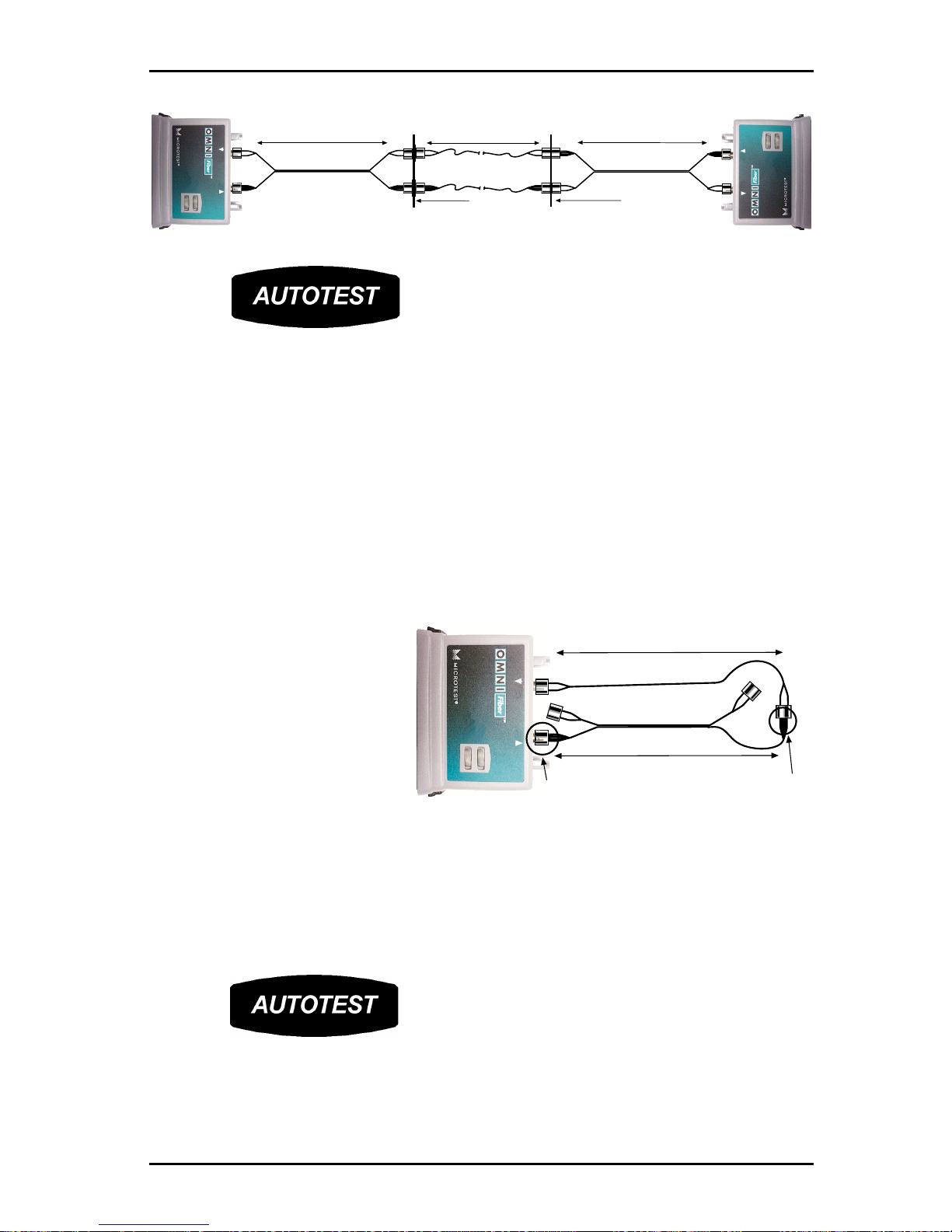
3 JUMPER METHOD AUTOTEST
T o run an Autotest when the 3-Jumper Method was used to set the Reference proceed as follows:
1. Do not disconnect the launch cables that are attached to the OMNI
Fiber
.
2. Remove the middle launch cable and the connector sleeves that were
attached to the middle launch cable.
3. Connect the OMNI
Fiber
Main to one end of the duplex link under test
and the OMNI
Fiber
Remote to the opposite end.
RX
TX
850 nm
1300/1310 nm
RX
TX
850 nm
1300/1310 nm
2 m Launch Cable
2 m Launch Cable
Patch Panel
Wall Plate
Cable under Test
Page 41
3 - 7
OMNIScanner User Guide
4. Press .
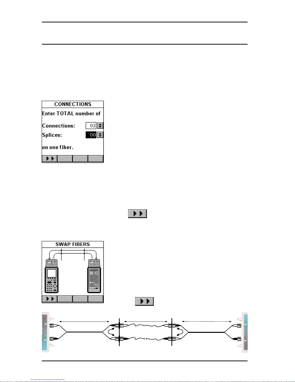
Loopback Autotest using OMNI
Fiber
Main
This configuration is used to test single fibers, reels and short cables when
both ends of the fiber under test are accessible from the same location.
Note: The loopback Autotest assumes that the 2-Jumper Method was used
to make the reference measurement.
T o run a Loopback Autotest proceed as follows:
1. Do not disconnect the
black launch cable, which is
attached to the TX port of the
OMNI
Fiber
(it is circled in the
graphic).
2. Do not disconnect the
coupler from the black
launch cable (it is circled in
the graphic).
3. Disconnect the white launch cable from the RX port of the OMNI
Fiber
and the connector sleeve. Leave the two white connectors dangling.
4. Attach the cable to be tested to the RX port on the OMNI
Fiber
and the
connector sleeve.
5. Press .
RX
TX
850 nm
1300/1310 nm
RX
TX
850 nm
1300/1310 nm
2 m Launch Cable
2 m Launch Cable
Patch Panel
Wall Plate
Cable under Test
RX
TX
850 nm
1300/1310 nm
2 m Launch Cable
Fixed Connection
Fixed Connection
Cable under Test
Page 42
OMNIScanner User Guide
3 - 8
Running a Fiber Autotest
Some Autotests do not have a fixed loss limit. The Optical Link Budget
(OLB) is calculated based on the wavelength, the length of the cable, and
the number of connectors and splices.
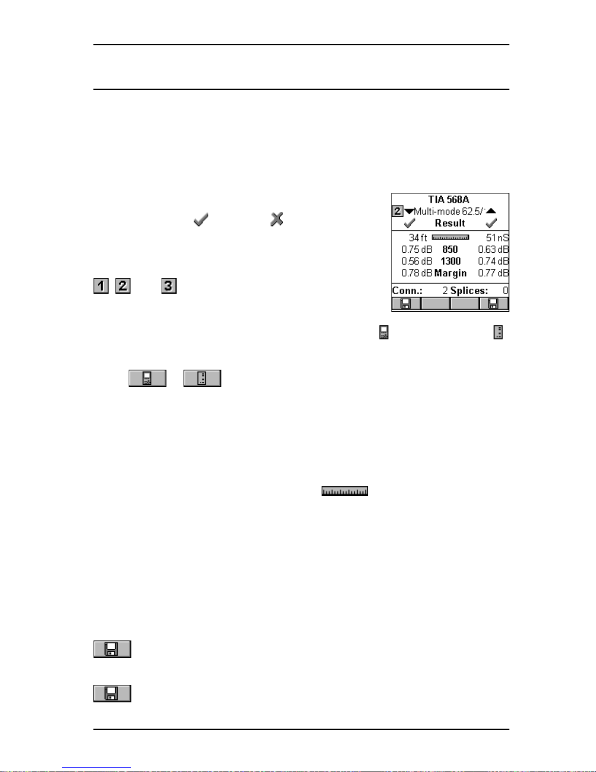
OMNI
Scanner
will automatically display the CONNECTIONS screen if you
are running an equation based Autotest (TIA 568A, ISO 1 1801, or 1000
Base F).
1. With the Connections: field highlighted, press
ENTER. Use the é or ê arrow key to adjust the
number of connections in your link. To determine
the total number of connections, simply count all
of the connections (connector pairs) on one fiber.
OMNI
Scanner
will assume that both fibers of a
duplex link have the same number of connections.
2. To change the number of Splices, use the ê to highlight the field and
press ENTER. Use the é or ê arrow key to adjust the number of splices in
your link. To determine the total number of splices, simply count all of the
splices on one fiber. OMNI
Scanner
will assume that both fibers of a duplex
link have the same amount of splices.
3. After editing the fields, press to run the Autotest.
OMNI
Scanner
starts the Autotest after the number of connections and
splices has been entered.
Note: If you are running a Two Way test, you will
be prompted to swap the fibers. (See Chapter 4 Setup: Fiber T est Options for further informa-
tion.)
4. Swap the Launch Cable’s connectors as
indicated in the graphic. Do not disconnect the
Launch Cables from the OMNI
Fiber
!
5. Press to complete the Autotest.
RX
TX
RX
TX
2 m Launch Cable
2 m Launch Cable
Cable under Test
Page 43
3 - 9
OMNIScanner User Guide
Fiber Autotest Results
Once the Autotest is completed the Autotest screen will be displayed.
The arrows at the top of the screen indicate the direction of the light.
▼ points to the result measured from OMNIRemote to OMNI
Scanner.
▲ points out the result measured from OMNI
Scanner
to OMNI
Remote.
The overall test result for each fiber is located right
below the arrows, (P ASS) or (FAIL).
The name of the Autotest is displayed at the top of
the screen followed by the name of the fiber .
, , and indicate the method that was used to
set the reference, 1 Jumper , 2 Jumpers, or 3 Jumpers.
When a bidirectional test was performed an icon for OMNI
Scanner
or
OMNI
Remote
will appear next to the fiber‘s name.
Press or to view results for the fibers with light transmission
in the opposite direction. The arrows flip vertically to indicate that there are
two results for each fiber, one from TX to RX and one from RX to TX.
Note: Values measured with OMNIFiber will be compared against the
preprogrammed P ASS/F AIL limits. OMNIScanner will report independent
PASS/FAIL indication for both fibers.
The Autotest Results screen displays the (Length) and the loss.
Further , the margin is displayed. It is the worst case margin for all wavelengths on each fiber in both directions. A positive margin indicates that the
measured loss was less than the P ASS/F AIL value, a negative margin
indicates a fail and shows how much the measurement exceeded the
maximum allowable P ASS/FAIL amount.
The number of Connections and Splices is displayed at the bottom of the
screen (if applicable).
To store the Autotest Result for the fiber listed on the right side, press the
(Save) function key located on the right side.
To store the Autotest Result for the fiber listed on the left side, press the
(Save) function key located on the left side.
Page 44

OMNIScanner User Guide
3 - 10
Page 45
4 - 1
OMNIScanner User Guide
Chapter 4 - Setup
Configuring OMNIScanner
OMNI
Scanner’s
easy-to-use setup feature allows you to define, edit and
preset many items. They are conveniently organized and can be easily
accessed by pressing the assigned number on your alphanumeric keypad,
or by highlighting the item and then pressing ENTER.
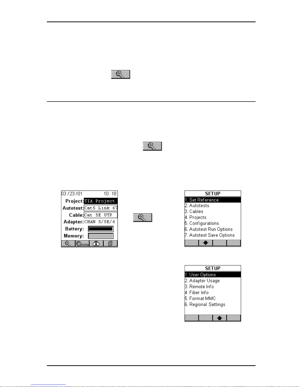
From the Project screen press the (Setup) function key to open the
SETUP screen.
è
è
è
Page 46
OMNIScanner User Guide
4 - 2
Set Reference
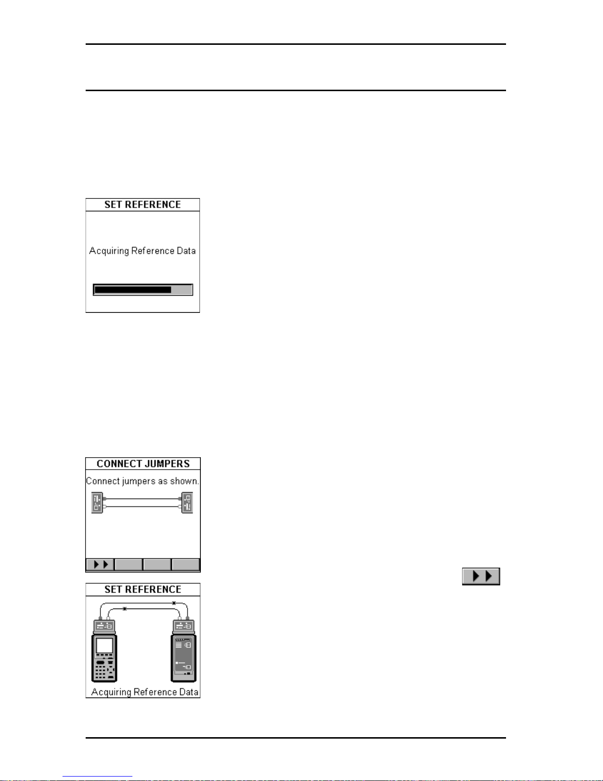
Connect OMNI
Scanner
and OMNI
Remote
through their test connector
ports using the Link Adapter and the Channel Adapter*. Select Set Refer-
ence to display the SET REFERENCE screen. OMNI
Scanner
will immedi-
ately start to communicate with OMNI
Remote
.
*Use the Set Reference Adapter with OMNIScanner L T.
While the reference data is being established, a
gauge indicates the progress.
OMNI
Scanner
notifies you when the process has
been completed. The REMOTE INFO screen will be
displayed.
Note: Set Reference is needed to periodically verify
and establish the signal reference for attenuation.
Press ESC to return to the SETUP screen.
Set Reference with the OMNIFiber Adapters
Note: The fiber reference expires each day at midnight. It must be set each
calendar day that OMNIFiber adapters are used. The reference value
should also be set every time the test configuration changes.
A reference value must be established before a loss
measurement can be calculated.
With the OMNI
Fiber
adapters attached to OMNI-
Scanner
and OMNI
Remote
, and the launch cable(s)
(jumper(s))in place, select Set Reference to display
the CONNECT JUMPERS screen.
Connect the jumpers as displayed and press
to continue.
The SET REFERENCE screen will be displayed
while the reference data is being established.
OMNI
Scanner
notifies you when the process has
been completed and the FIBER INFO screen will be
displayed.
Press ESC to return to the SETUP screen.
Page 47
4 - 3
OMNIScanner User Guide
Autotests
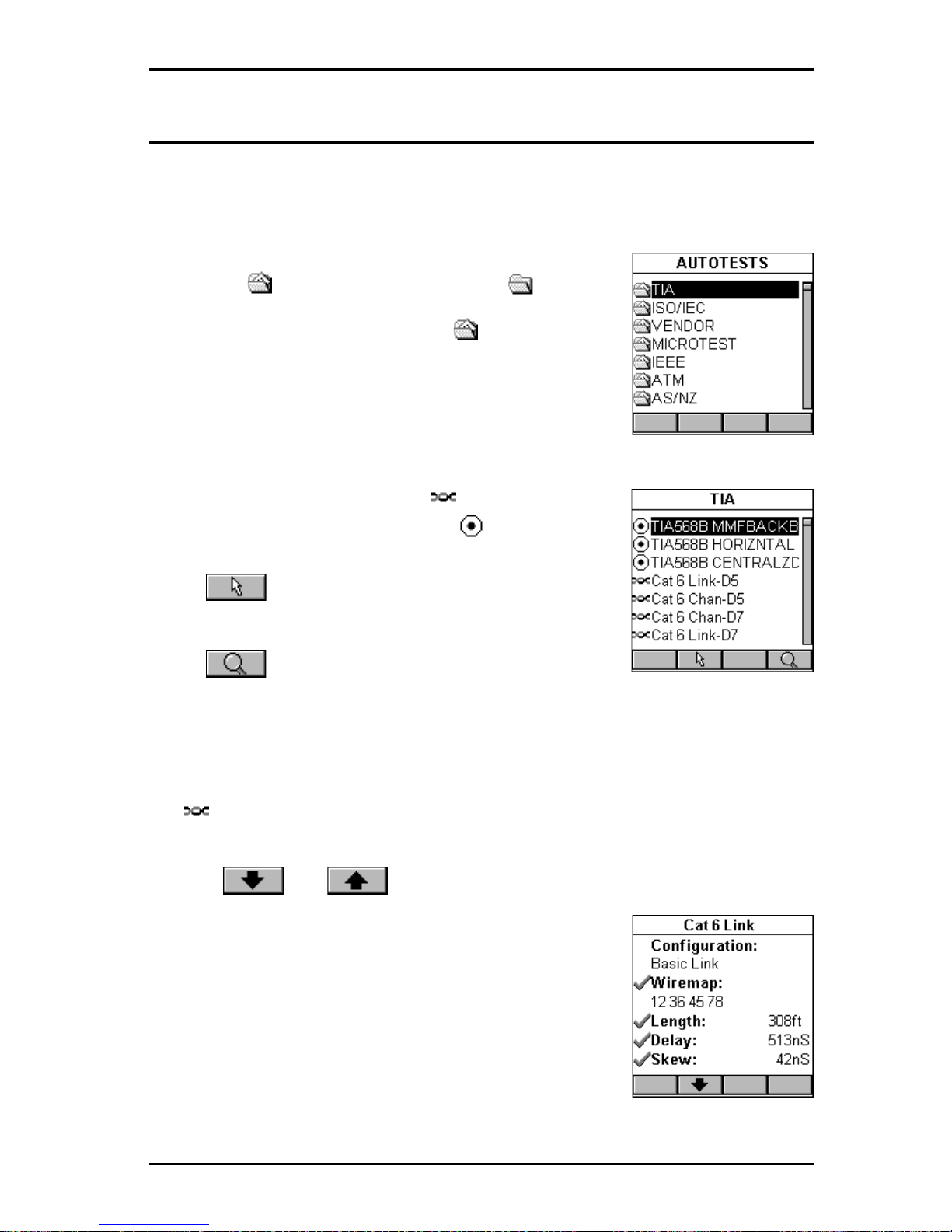
Select Autotests to display the AUTOTESTS screen. It contains a list of
standard Autotest specifications supported by OMNI
Scanner
. Standards
are grouped by TIA, ISO, VENDOR, MICROTEST, IEEE, ATM, and AS/NZ.
If there are Autotest specifications in a folder, it will
appear full , otherwise it will be empty .
Highlight a folder containing items and press
ENTER to display the list of Autotests contained in
that folder.
Use the é or ê arrow key to highlight a specific
Autotest.
Copper tests are marked with a twisted pair icon.
Fiber optic tests are marked with a fiber icon.
Press (Set Default) to select it as the Autotest
to run.
Press (Detail) to review the Autotest’s limits.
Viewing Details for Copper and Fiber Autotests
For twisted pair cabling the Autotest Detail screen consists of four
pages.
Use the and function keys to browse through the pages.
The screen titles show the standard being used to set
the limits (e.g. Cat 6 Link).
The first page displays the Configuration of the
Autotest (Basic Link, Channel, or Permanent Link).
Wiremap, Length, Delay and Skew limits are also
displayed. The Wiremap numbers show the pairs that
are being tested.
Page 48
OMNIScanner User Guide
4 - 4
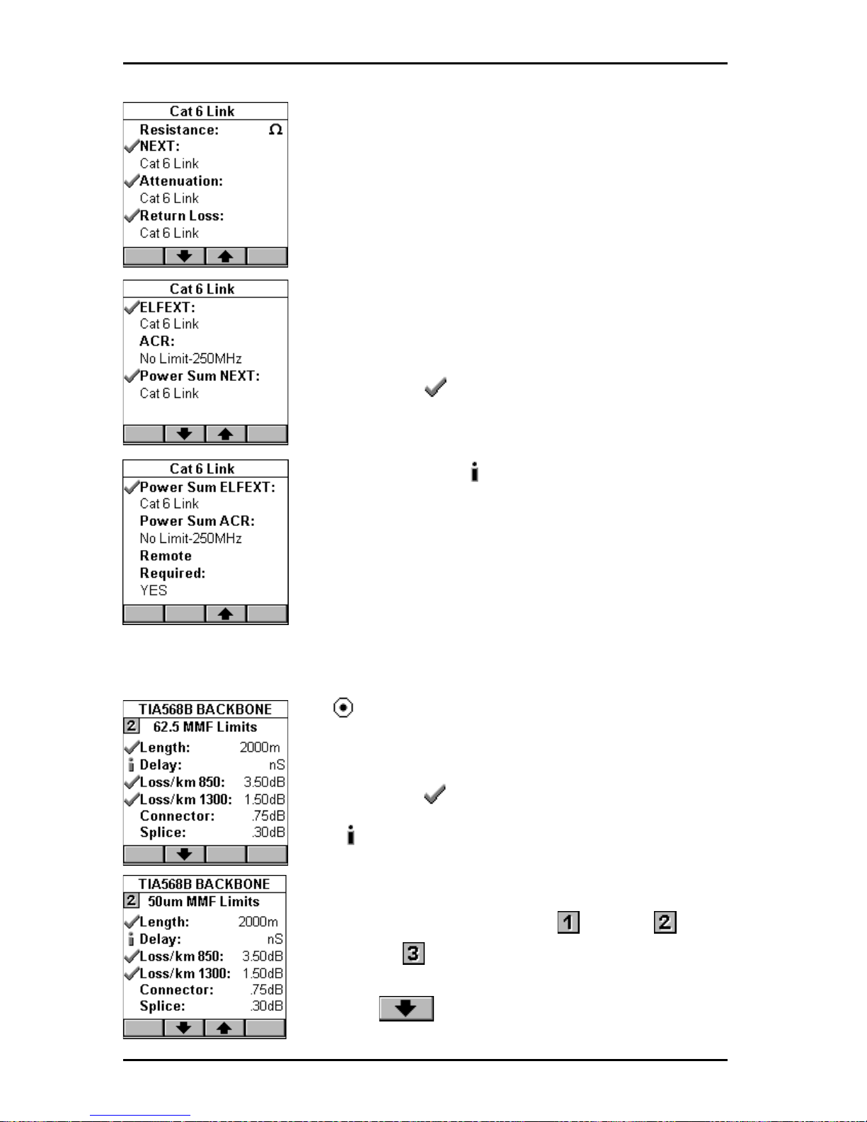
The second page shows limits for Resistance,
NEXT, Attenuation, and Return Loss.
The third page lists limits for ELFEXT, ACR, and
Power Sum NEXT measurements.
The fourth page shows limits for Power Sum
ELFEXT and Power Sum ACR. This screen also
informs you whether or not OMNI
Remote
is required
to perform the selected Autotest.
Test that are performed during an Autotest are
clearly marked . Tests that are not required when
performing an Autotest have no icon.
Disabled tests may or may not show limits in the
description field. An precedes the test name for
tests being performed during the Autotest, but the
results are not used to determine PASS or FAIL.
Defined test limits will be displayed right below the
test name. If a test has no limit, the limit description
field will be empty .
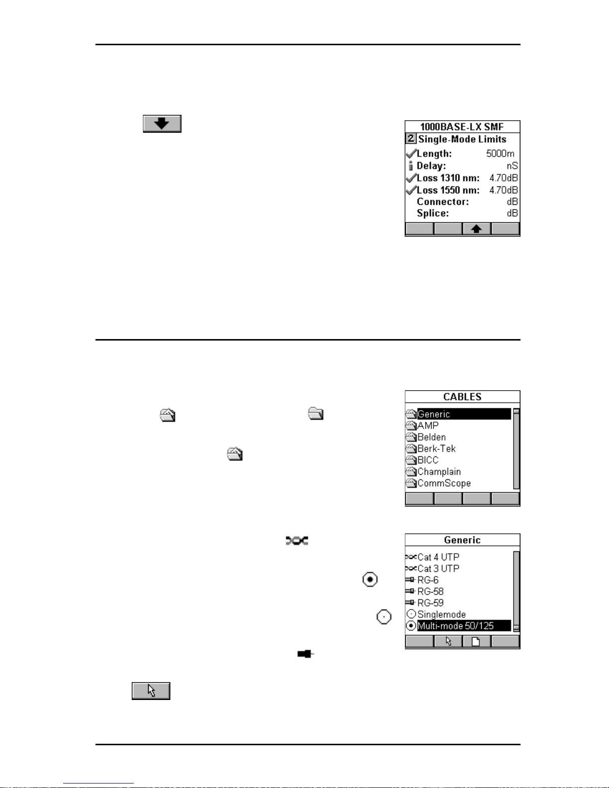
For fiber optic cabling the View Autotest Detail
screen shows the standard being used in the titlebar.
The test that are performed during an Autotest are
clearly marked .
If an precedes the test name, the test will be
performed for information purpose only; the results
are not used to determine PASS or FAIL.
The required reference method Jumper,
Jumpers, or Jumpers is displayed in the View
Autotest Detail screen together with the test limits.
Use the function key to view the limits for
Page 49
4 - 5
OMNIScanner User Guide
50 µm fibers. When running an Autotest, OMNIScanner will choose the
appropriate Autotest limits based on the selected fiber.
Use the function key to view the limits for
single-mode fibers.
When viewing limits for equation-based Autotests like
TIA 568B, ISO 11801, and 100Base-F , the Loss per
km (kilometer) will be displayed.
For all other tests the Loss for 850nm, 1300nm,
1310nm, and/or 1550nm is displayed.
Press ESC to return to the SETUP screen.
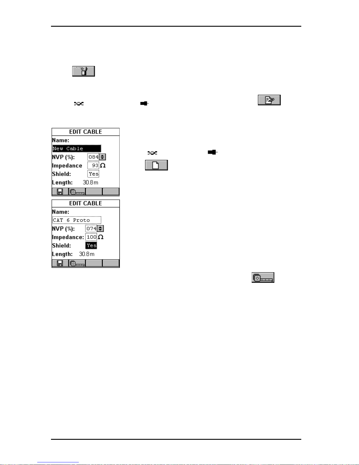
Cables
Select Cables to display the CABLES screen. It contains a list of cable
manufacturers.
If there are cables in a folder , the manufacturer folder
will appear full, otherwise it will be empty.
Highlight a cable manufacturer that is marked by a
folder containing items and press ENTER to
display the list of cables in that manufacturer’s folder.
Use the é or ê arrow key to highlight the desired
cable.
Copper cables are marked with a twisted pair
icon.
Multimode fiber optic cables are marked with a
fiber icon.
Single-mode fiber optic cables are marked with a
fiber icon.
Coaxial cables are marked with the COAX icon.
Press (Set Default) to select the cable to be tested.
Selecting the correct cable type will ensure accurate length measurements.
Page 50
OMNIScanner User Guide
4 - 6
If you cannot find or do not know the name of your cable manufacturer,
simply select a cable from the Generic folder , or create a new cable.
Press (Delete) to permanently remove a custom cable.
Note:
Default cables cannot be removed.
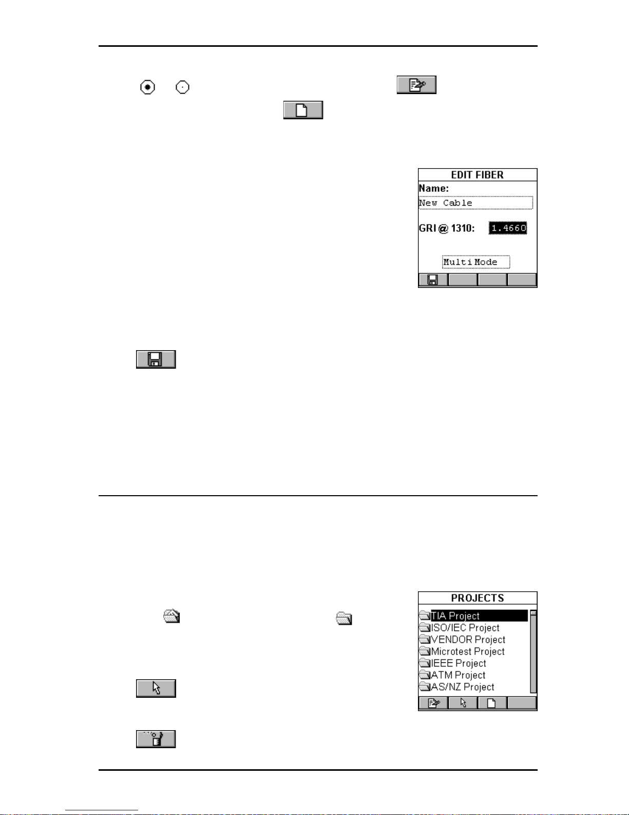
With a twisted pair or a coaxial cable highlighted, press (Edit)
to edit an existing custom cable. Cable Name, NVP, or Impedance can be
changed.
Note: Default cables cannot be edited.
With a twisted pair or coax cable highlighted,
press (New) to create a new cable based on
the NVP and Impedance values of the highlighted
cable. Name, NVP, and Impedance are definable.
Note: A new or edited cable will be saved in the
Custom Cables folder.
For an accurate Length test, the NVP (Nominal
V elocity of Propagation) must be set correctly. The
value is usually specified by the cable vendor , and
OMNI
Scanner
has a large library of cables with the
manufacturer’s specified NVP.
To determine the NVP of a cable with a known length, press
(Measure) to capture the length of the cable using the displayed NVP. Use
the ê to highlight the NVP: field and press ENTER. Use the é or ê arrow
key to increase or decrease the value by 1% (percent) and adjust the NVP
until the known length is displayed. The Length: changes accordingly.
Note: The known cable must have a length of at least 50 feet or 15 meters.
To change the Impedance; use the ê to highlight the field and press
ENTER. Use the é or ê arrow key to select the appropriate Impedance in
ΩΩ
ΩΩ
Ω (Ohms) from the predefined list.
To setup whether or not the cable is shielded, use the ê to highlight
Shield: and press ENTER. Use the é or ê arrow key to make the appro-
priate selection. If ‘Yes’ is selected, the wiring for the shield will be measured during the Autotest and used to determine if the Wiremap will PASS
or F AIL.
Page 51
4 - 7
OMNIScanner User Guide
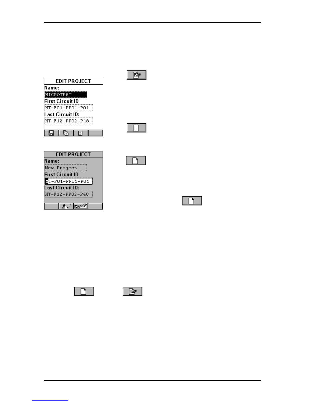
With a or fiber optic cable highlighted, press (Edit) to edit an
existing custom cable, or press (New) to create a new fiber based
on the GRI values of the highlighted cable. Cable Name and GRI @ 1300
(multimode) or 1310 (single-mode) can be viewed and changed.
Note: Default fibers cannot be edited.
A fiber cable’s Graded Refractive Index (GRI) differs
depending on the supplier. To receive accurate
length results, OMNIScanner allows you to define
the GRI values for both wavelengths.
To change the fiber’s mode, use the é or ê arrow
key to highlight the mode. Press Enter to select
Multimode 62.2
µµ
µµ
µm, Multimode 50
µµ
µµ
µm or Single-mode.
Press (Save) to save the edited cable into the Custom Cable folder.
Press ESC to return to the CABLES screen.
Projects
Select Projects to display the PROJECTS screen. It contains a list of all
projects that are currently stored in OMNI
Scanner
. Predefined default
projects are: TIA, ISO/IEC, VENDOR, Microtest, IEEE, A TM, AS/NZ, ANSI.
OMNI
Scanner
’s project feature allows you to organize test specifications,
cables types, and test results into Projects.
If there are tests stored in a project the folder will
appear full , otherwise it will be empty .
Use the é or ê arrow key to highlight a specific
Project.
Press (Set Default) to select it as the Project
to be used and to return to the SETUP screen.
Press (Delete) to permanently remove a project.
Page 52
OMNIScanner User Guide
4 - 8
Note: Default Projects cannot be deleted. Only projects without stored
Autotests can be deleted.
Press (Edit) to edit an existing project and its
Circuit ID.
The project name will appear in the Name: field. The
first and last Circuit ID fields contain a default circuit
ID.
(See Editing a Circuit ID for further information.)
Press (List) to display the Circuit ID screen.
It contains a scrollable list of all Circuit IDs created
for the project.
Press (New) to create a new project.
The Name: field is initially empty. Press ENTER to
edit the name. The first and last Circuit ID fields
contain the default Circuit ID from the Project that
was highlighted when the (New) key was
pressed.
Note: New and edited project names are placed at the bottom of the list in
the PROJECTS screen. OMNIScanner can store up to 16 projects.
Editing a Circuit ID
To edit or create a Circuit ID, highlight an item in the PROJECTS screen
and press (New) or (Edit).
Use the ê to highlight the First Circuit ID: field and press ENTER.
The Circuit ID consists of 16 characters, which allows the sophisticated
construction of Circuit IDs. Each character can be incremented.
The example shows how to quickly create an incremental Circuit ID.
Enter MT-F01 (MICROTEST - Floor 01)
-PP01 (- Patch Panel 01) -P01 (-
Position 01) in the First Circuit ID: field.
Page 53
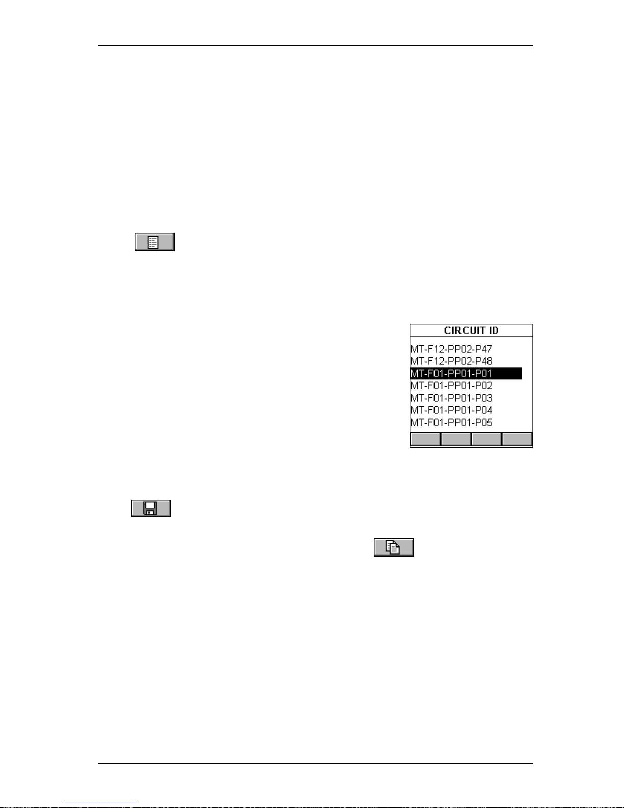
4 - 9
OMNIScanner User Guide
Press ENTER to terminate the edit mode.
Use the ê to highlight the Last Circuit ID: field and press ENTER.
Enter MT-F12 (MICROTEST - Floor 12)
-PP02 (- Patch Panel 02) -P48 (Position 48) in the Last Circuit ID: field. Press ENTER to terminate the
edit mode.
The Circuit IDs will increment from right to left. The positions will change
first from 01 to 48. Next the Patch Panels will increase from 01 to 02. Last
the floors will increase from 01 to 12.
Press (List) to review the continuous list of Circuit IDs that was just
created.
MT-F01-PP01-P01 (1st Circuit ID to be used)
MT-F01-PP01-P02 (2nd Circuit ID to be used)
MT-F01-PP01-P03 (3rd Circuit ID to be used)
.
.
.
MT-F01-PP01-P48 (48th Circuit ID to be used)
MT-F01-PP02-P01 (49th Circuit ID to be used)
..
..
..
MT-F01-PP02-P48 (96th Circuit ID to be used)
MT-F02-PP01-P01 (97th Circuit ID to be used)
MT-F02-PP01-P02 (98th Circuit ID to be used)
...
...
...
MT-F12-PP02-P48 (last Circuit ID to be used)
Press
(Save) to save the Circuit ID and return to the PROJECTS screen.
Note: To quickly edit the Last Circuit ID, press (Copy) once you
have completed the First Circuit ID. This function will copy the First Circuit
ID into the Last Circuit ID field. Now edit the Last Circuit ID field.
Press ESC to return to the SETUP screen.
Page 54
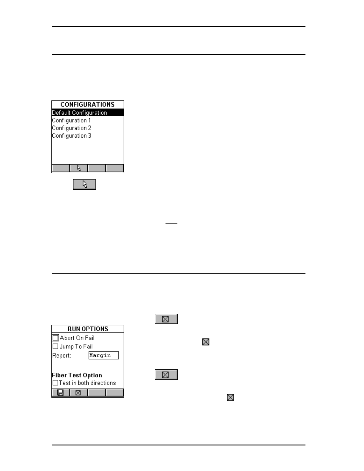
OMNIScanner User Guide
4 - 10
Configurations
Select Configurations to display the CONFIGURATIONS screen. It
contains a list of all configurations which are currently stored on the
MultiMediaCard that can be read by OMNI
Scanner2. (See Chapter 1 1 -
MultiMediaCard for more information about the MMC)
.
The predefined Default Configuration is always
present and can be used to reset OMNI
Scanner
to
the factory default. It contains the following
projects: TIA, ISO/IEC, VENDOR, Microtest, IEEE,
ATM, AS/NZ, ANSI.
OMNIScanner2 only: Use the é or ê arrow key
to highlight a specific Configuration.
Press (Set Default) to select it as the Configuration to be used and
to return to the SETUP screen.
While the selected Configuration is being loaded onto OMNI
Scanner2
, a
gauge indicates the progress. Do not remove the MultiMediaCard from
OMNIScanner2 during the data transfer.
Autotest Run Options
Select Autotest Run Options to display the RUN OPTIONS screen. With
the presented options you are able to further customize the way OMNIScanner will perform an Autotest.
Press if you want OMNI
Scanner
to abort
the Autotest if a F AIL occurs. The Abort on Fail
box will be checked .
Use the ê to highlight the next checkbox.
Press if you want OMNI
Scanner
to auto-
matically move to the failed test result. The Jump
to Fail box will be checked .
Use the ê to advance to the Report: field and press ENTER. Select
Margin if you want OMNIScanner to report the result, measured in dB, for
the worst margin. Select Worst dB if you want the worst overall dB value to
Page 55
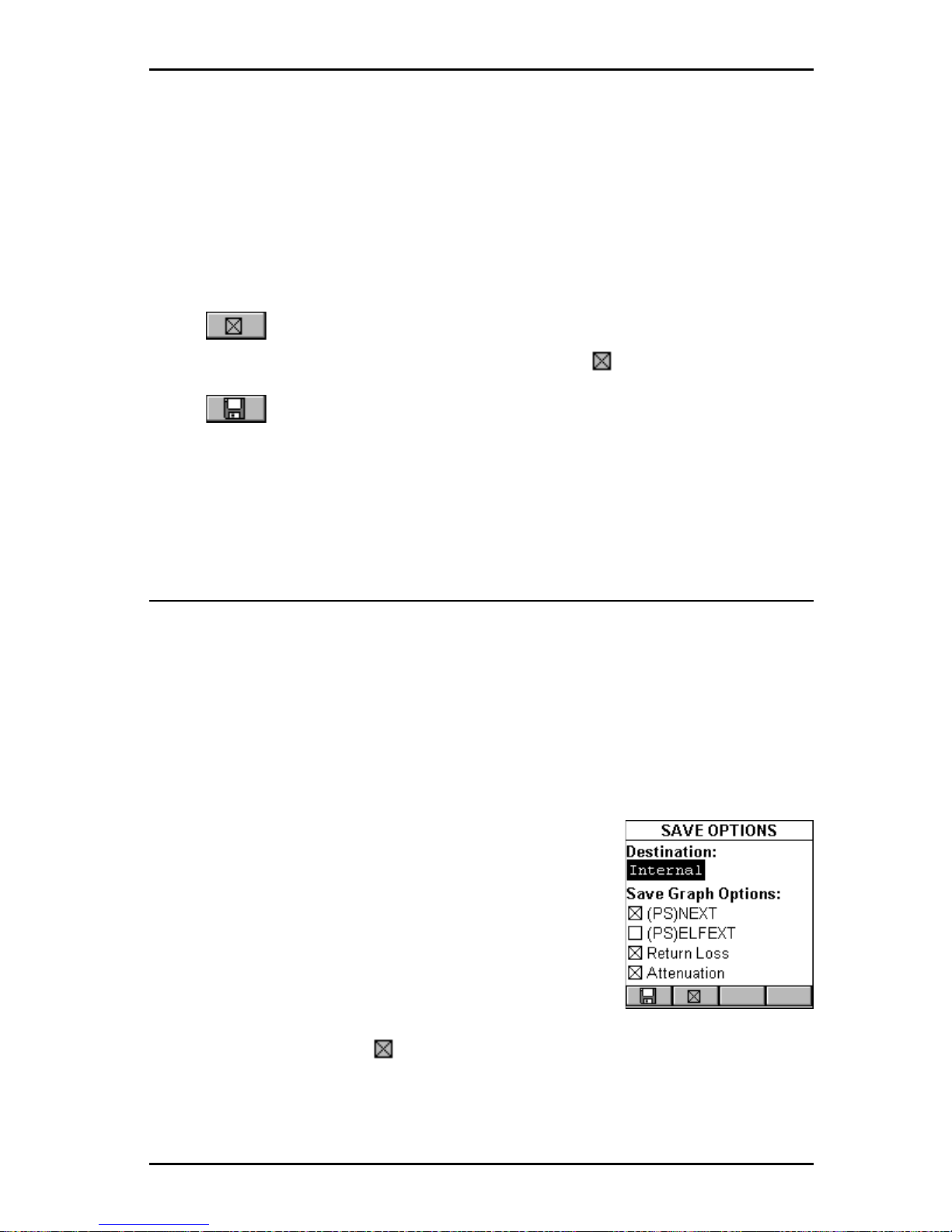
4 - 11
OMNIScanner User Guide
be reported, as in OMNIScanner software versions prior to v4.0. Press
ENTER to set the default.
Note: Attenuation results in dB will always be reported for the worst value,
regardless of what is selected in the Report: listbox.
Use the ê to highlight the Fiber T est Options checkbox. You will be able
to define the way fiber optic Autotests are performed.
Press if you want OMNI
Fiber
to test the fiber link in both directions.
The Test in Both Directions box will be checked .
Press (Save) to save your changes and return to the SETUP screen.
Press ESC to discard all changes and return to the SETUP screen.
Autotest Save Options
Select Autotest Save Options to display the SAVE OPTIONS screen. This
screen contains several options that allow you to customize the way
OMNIScanner will save Autotests.
OMNIScanner2 only: Press ENTER to change the Destination: from MMC
(MultiMediaCardTM) to Internal. Use the éê keys to highlight the desired
destination and press ENTER to select it as the default destination. Select
MMC if you want to collect test results on the MultiMediaCard.
(See Chapter 1 1 - MultiMediaCard for more information about MMC.)
Select Internal if you want to
save the results to OMNI
Scanner
’s internal memory.
In either case, results can be transferred to the
ScanlinkTM Tools software program.
(See Chapter 9
- Uploading and Printing for more information.)
In the Save Graph Options section you will be able
to define which of the graphs will be saved.
If a checkbox is checked , OMNI
Scanner
will store an Autotest with the
graph information for that particular test.
Note: Saving graphs reduces the
number of Autotest that can be stored.
Page 56
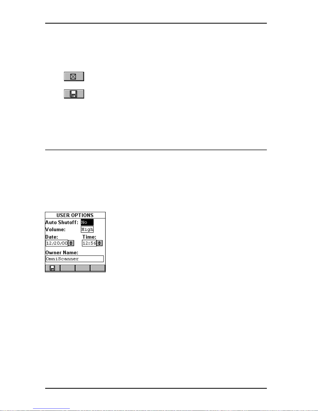
OMNIScanner User Guide
4 - 12
Depending on the performed Autotest, NEXT/PSNEXT, ELFEXT/PSELFEXT, Return Loss, and Attenuation graphs can be saved.
Use the éê to highlight the Save Graph Option checkboxes.
Press to select the graph to be saved.
Press (Save) to save your changes and return to the SETUP screen.
Press ESC to discard the changes and return to the SETUP screen.
User Options
Select User Options to display the USER OPTIONS screen. This screen
contains several user definable preferences.
Press ENTER to turn the Auto Shutoff on or off. Select YES if you want
OMNI
Scanner
to automatically shut off after 10 minutes when operated
with battery power. Select NO if you don’t want to use the function. Press
ENTER to set the default.
Use the è to advance to the Volume: field and
press ENTER. OMNIScanner has a 3 setting volume
control: Select High if you want to use the default
volume, select Low to turn the volume down, and
select OFF to turn the sound off. Use the éê keys
to highlight the desired volume and press ENTER to
select it as the default volume.
To edit the Date (Month/Day/Year) use the è key to highlight the portions
you want to change. Press ENTER to edit the highlighted segment. Use the
éê keys to change the displayed values in increments of 1. Press ENTER
when done.
To edit the Time use the è key to highlight the portions you want to
change. Press ENTER to edit the highlighted segment. Use the éê keys
to change the displayed values in increments of 1. Press ENTER when
done.
Use the è to highlight the Owner Name:. Press ENTER to start the edit
mode. You can enter up to 19 characters for the Owner Name. The owner
Page 57
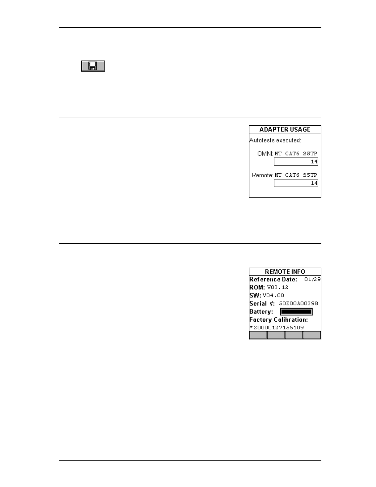
4 - 13
OMNIScanner User Guide
name will appear on printed reports. Press ENTER to end the edit mode.
Press to save all settings and return to the SETUP screen.
Adapter Usage
Select Adapter Usage to display the ADAPTER
USAGE screen.
The number of Autotests that have been performed
with the Adapter that is currently attached to OMNI:
and Remote: is displayed below each adapter’s
name (Adapter ID String).
Press ESC to return to the SETUP screen.
Remote Info
Select Remote Info to display the REMOTE INFO screen.
The date the Reference value for OMNI
Scanner
and
OMNI
Remote
was last set is shown at the top of the
screen.
The Hardware and Software Versions, and the
Serial number of the remote unit are displayed.
The Battery status is represented with a gauge.
Factory Calibration* data is displayed at the bottom
of the screen.
You may need to provide Serial Number and Factory Calibration data when
having repairs or refurbishments done, or when calling for Technical
Support.
Press ESC to return to the SETUP screen.
*OMNI
Scanner
and OMNI
Remote
should be calibrated annually with
specialized Microtest equipment. Contact Microtest Technical Support for
information on calibration and service requirements.
Page 58
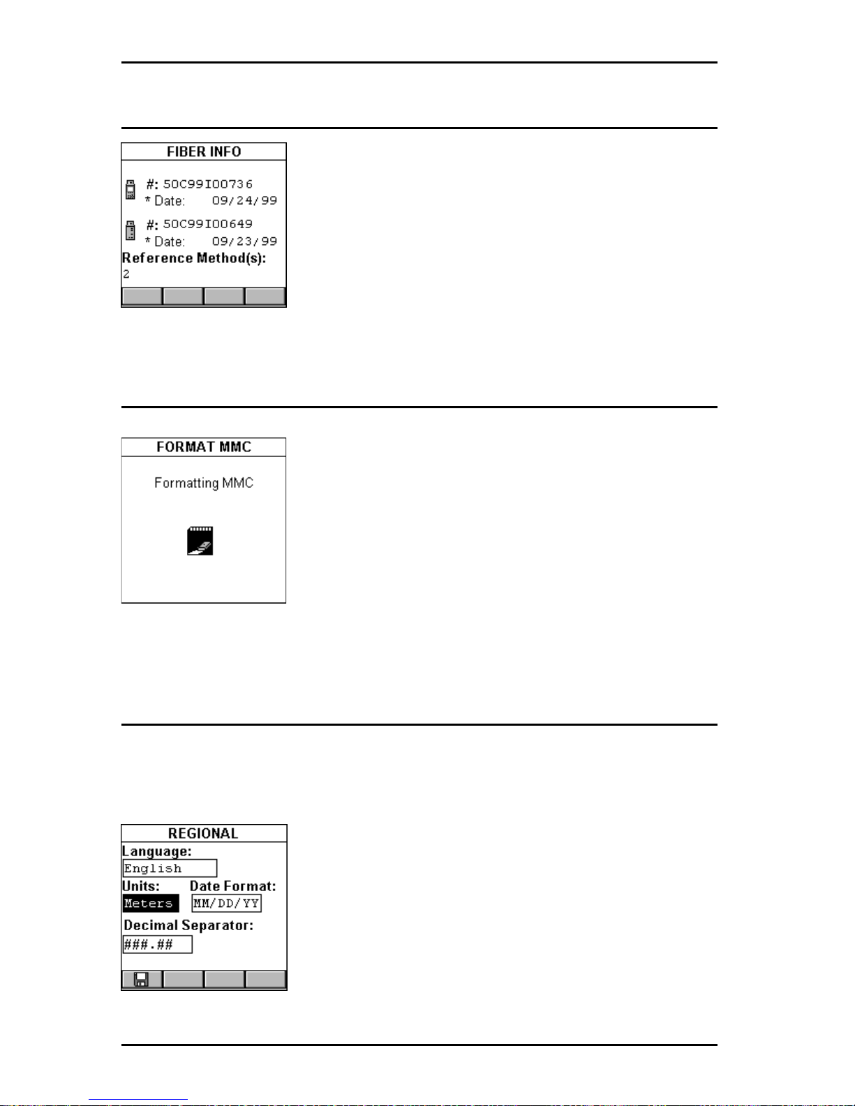
OMNIScanner User Guide
4 - 14
Fiber Adapter Info
Select Fiber Info to display the FIBER INFO screen.
The Serial numbers and the date the adapters were
last factory calibrated is displayed.
The currently used reference method(s) are dis-
played on the bottom of the screen.
Press ESC to return to the SETUP screen.
Format MMC
OMNIScanner2 only: When using the
MultiMediaCard for the first time, it may require
formatting.
Insert the MMC into OMNIScanner2’s MMC slot.
Select Format MMC to open the FORMAT MMC
screen. Formatting will start immediately .
The formatting time is dependent on the capacity of
the MultiMediaCard, 8MB will require 2 minutes.
Regional Settings
Select Regional Settings to open the REGIONAL screen. The settings
affect the way OMNI
Scanner
displays dates and numbers.
The REGIONAL screen displays the Language
that is currently selected. To change the language,
press ENTER and use the éê keys to highlight a
language. Press ENTER once more to select it as
the default language.
Use the è to advance to the Units: field. Press
ENTER to switch the units from Meters to Feet.
Use the éê keys to highlight the desired measurement unit and press ENTER to select it as the
default measurement.
Page 59

4 - 15
OMNIScanner User Guide
Use the è to advance to the Date: field. Press ENTER to change the date
format. DD is the day setting, MM is the month setting, YY is the year
setting. Use the éê keys to highlight the desired format and press ENTER
to select it as the default date format.
Use the è to advance to the Decimal Separator: field and switch the
decimal symbol from , (comma) to . (period). Use the éê keys to highlight
the desired symbol and press ENTER once more to select it as the default
separator.
Press to save all settings and return to the SETUP screen.
Page 60

OMNIScanner User Guide
4 - 16
Page 61
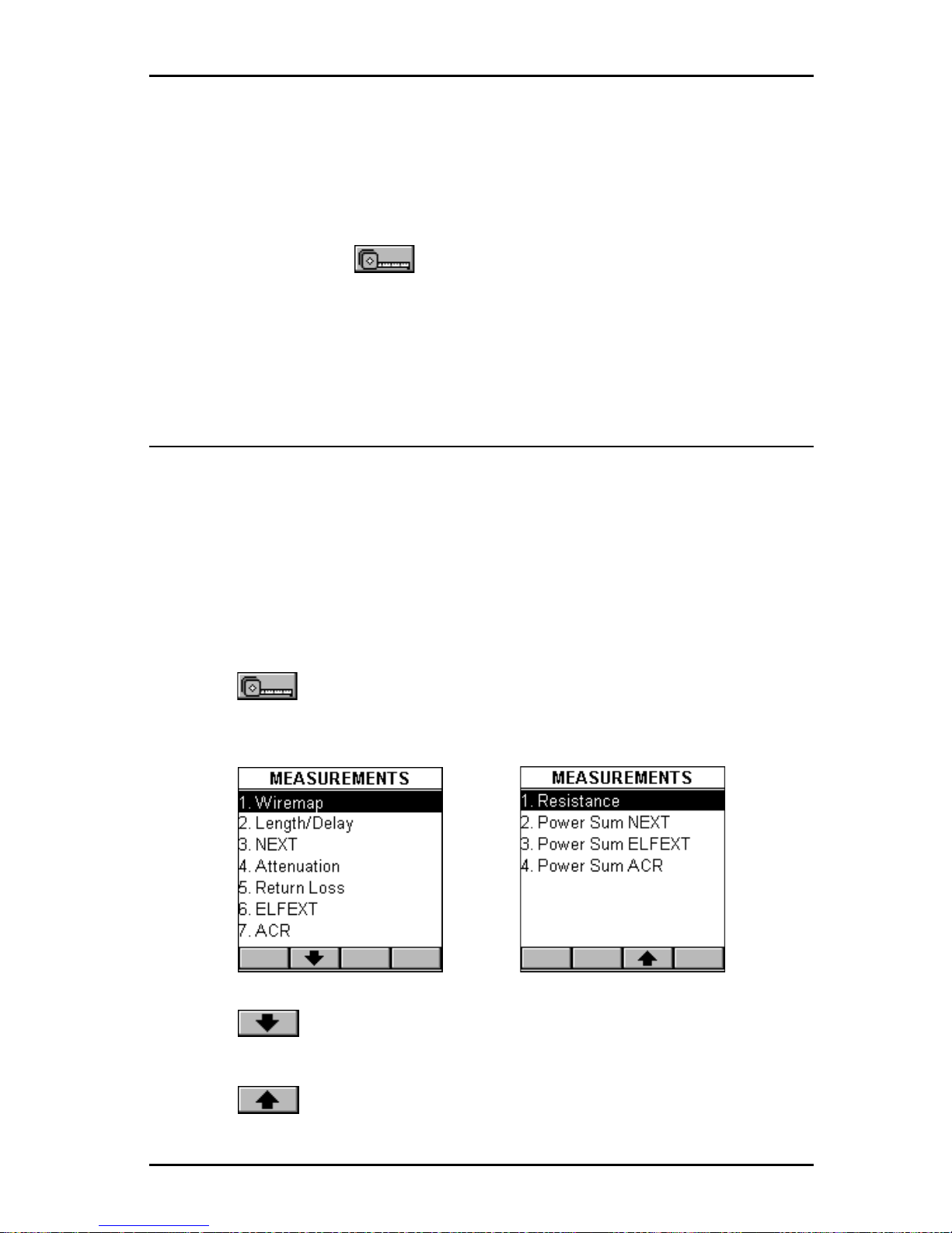
5 - 1
OMNIScanner User Guide
Chapter 5 - Measurements
Note: The list of tests in the Measurement screen changes depending on
the adapter that is currently attached to OMNIScanner.
Performing Individual Measurements with OMNIScanner
OMNI
Scanner
allows you to perform tests on twisted pair , fiber optic and
coaxial cabling.
Measuring Twisted Pair Cabling
OMNI
Scanner
allows you to run various individual tests. The tests are
conveniently grouped into two screens and can be accessed separately with
the alphanumeric keypad.
Press the (Measurements) function key to display the MEASURE-
MENTS screen.
Press the (Page Down) function key to scroll to the second screen
containing MEASUREMENTS.
Press the (Page Up) function key to return to the first screen containing MEASUREMENTS.
Page 62
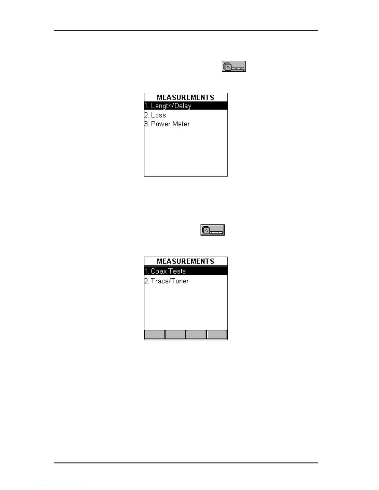
OMNIScanner User Guide
5 - 2
Measuring Fiber Optic Cabling
With the OMNI
Fiber
adapter attached, press the (Measurements)
function key to display the MEASUREMENTS screen for fiber optic cabling.
Measuring Coaxial Cabling
With the coax adapter attached, press the (Measurements) function
key to display the MEASUREMENTS screen for coaxial cabling.
Selecting an individual T est
Highlight the test you want to perform using the é or ê keys on your
keypad and press ENTER, or direct-dial a test by pressing its associated
number on the OMNI
Scanner
keypad.
Page 63
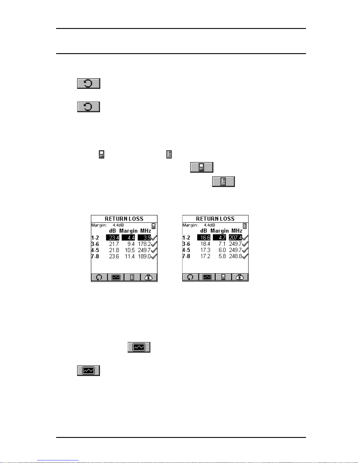
5 - 3
OMNIScanner User Guide
General Information
Most test result screens have a retest feature for diagnostic purposes.
Press (Retest) to run continuous tests for the same cable.
Press (Retest) once more to stop the continuous measurement.
OMNI
Scanner
will display the last measured data.
T ests that require the use of OMNI
Remote
will have small icons in the upper
right corner of the titlebar indicating whether the information on the screen is
pertinent for OMNI
Scanner
or OMNI
Remote
.
Toggle between the screens by pressing to open the screen that
contains the information for OMNI
Scanner
, and to display the
information for OMNI
Remote
.
Note: The P ASS/FAIL criteria are based on the Autotest currently selected
in the Project screen.
Several measurements will display results in a graph format. When a graph
can be displayed, the (Graph) function key is available.
Press (Graph) to display test results for the highlighted pair or pair
combination.
Use the é or ê keys to magnify the area of the graph where the cursor is
located. The graph can be magnified 1x, 2x, 4x, or 10x.
Page 64
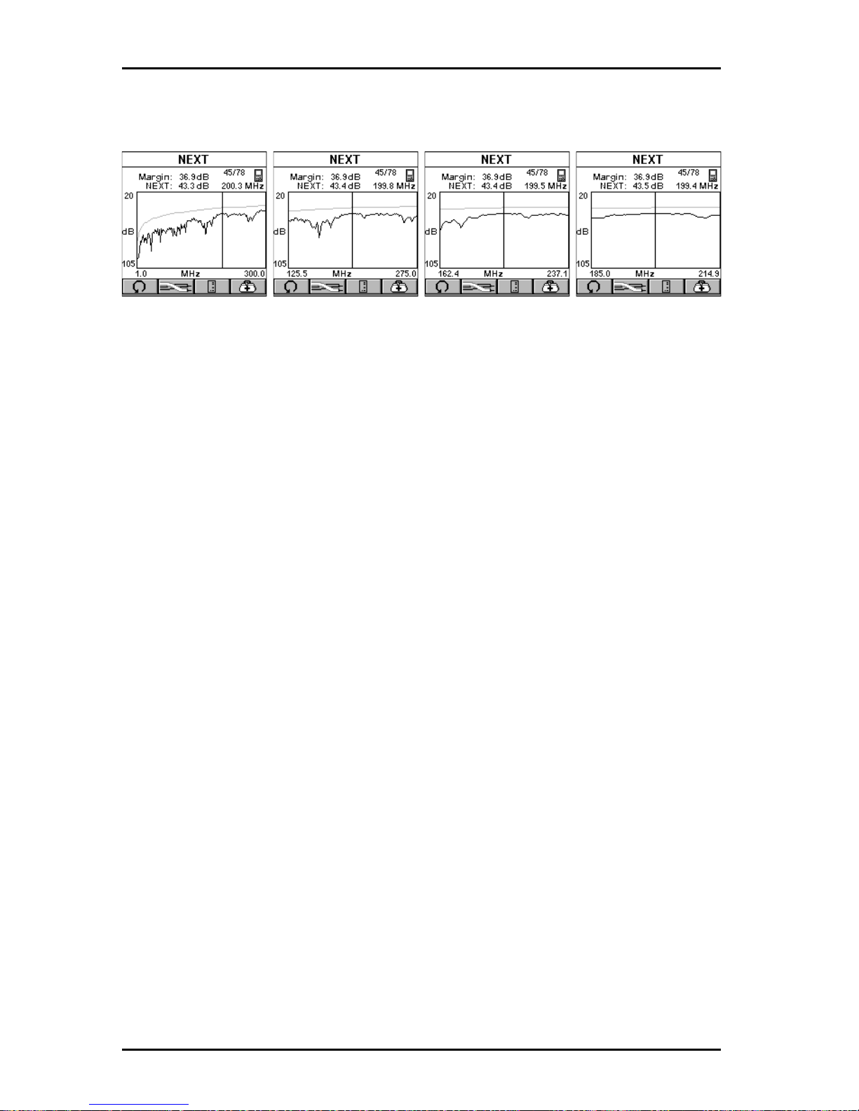
OMNIScanner User Guide
5 - 4
Use the ç or è keys to move the cursor within the graph.
1x 2x 4x 10x
Use the cursor to display values for the desired frequency .
Page 65
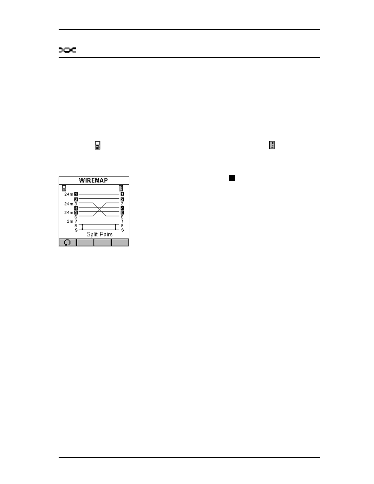
5 - 5
OMNIScanner User Guide
T wisted Pair Measurements with OMNIScanner
Wiremap
The Wiremap function tests twisted-pair cabling for proper wiring. Your
cabling configuration is checked for shield continuity , opens, shorts, crossed
pairs, split pairs, and reversed pairs. For each pair , Wiremap displays the
length.
The screen displays a graphical representation of the wiring in your cable,
where the near end wiring is shown on the left side, and the far end
wiring on the right side of the screen.
• A reverse video number indicates a split pair
• A straight line between pairs indicates a good pair
• No line between wire pairs indicates an open
• An X between a wire pair indicates a reversed pair
•A ] between wirepairs indicates a short
• The measured length of the pairs 1-2, 3-6, 4-5,
and 7-8 are shown on the left side.
In the example, OMNI
Scanner
displays split pairs on 1 - 2 and 4 - 5 (although they are wired straight through), a reversed pair 3 - 6, an open on
wire 7, and a short on wire 8 to the Shield.
Press ESC to exit the WIREMAP screen.
Length/Delay
The Length/Delay function measures a cable’s length, propagation delay
and skew . OMNI
Scanner
will determine whether the cable is open or
shorted.
The accuracy of the NVP (Nominal Velocity of Propagation) setting deter-
mines the exactness of the Length measurements. The NVP specified by
cable manufacturers is used for all the cables in OMNI
Scanner
’s library .
When creating or editing cables, the NVP value can be customized.
(See
Chapter 4 - Setup: Cables for further information.)
1
Page 66
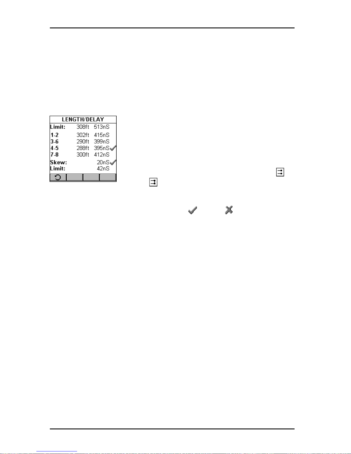
OMNIScanner User Guide
5 - 6
Delay is a measure of the time required for a pulse to travel from one end of
the link to the other. OMNI
Scanner
measures the delay from when the pulse
was sent to when the reflection was received. Knowing the speed that the
pulse propagates down the cable (NVP), OMNI
Scanner
then calculates the
length of the cable.
Skew is the difference between the pairs with the longest and shortest
delay.
The LENGTH/DELAY screen shows the test result
information for all pairs.
The Limit is displayed at the top of the screen.
The pairs are displayed in the first column followed by
small icons to indicate whether the pair is open or
shorted .
The measured Length and the Delay are displayed for each pair. The result
for the shortest pair is tagged with a P ASS or FAIL indicator.
If NEF (No End Found) is displayed instead of a value the cable is either too
long or properly terminated.
The length result can be displayed in meters or feet
(See Chapter 4: Setup -
User Options for further information.)
Delay is displayed in nS (nanoseconds).
The Skew value and the Skew limit are displayed right below the pairs.
Press ESC to exit the LENGTH/DELAY screen.
NEXT
The NEXT (Near End Crosstalk) function measures the electromagnetic
coupling that occurs between pairs at the near end. OMNI
Scanner
and
OMNI
Remote
allow NEXT to be measured at both ends of the link without
having to swap ends.
OMNI
Remote
functions as a terminator while OMNI
Scanner
transmits a
signal which is monitored on each of the other pairs. The received signal is
Page 67
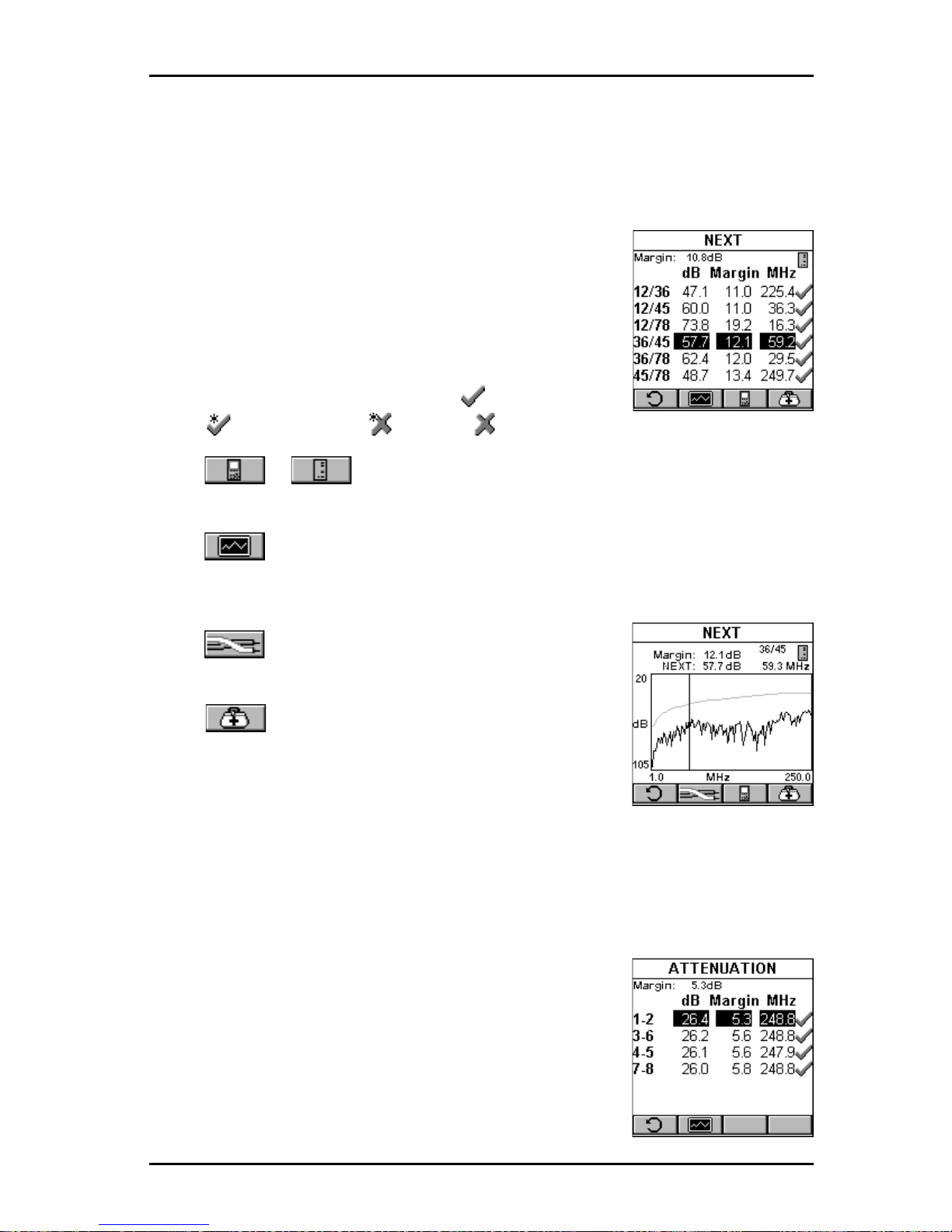
5 - 7
OMNIScanner User Guide
compared to the transmitted signal and the difference is reported as the
NEXT value in dB. When measuring the NEXT for the OMNI
Remote
end, the
roles of the two units are reversed. OMNI
Scanner
provides the termination;
OMNI
Remote
transmits and measures the signal.
In the NEXT screen, the worst case margin for all
near and far pair combinations is shown at the top of
the screen.
The pair combinations are displayed in the column on
the left side, followed by the measured NEXT value,
margin/limit, and frequency . The result for each pair
combination is tagged with a P ASS , Marginal
PASS , Marginal FAIL , or FAIL indicator.
Press or to toggle between the NEXT results for OMNI
Scan-
ner
and OMNI
Remote
.
Press (Graph) to display the NEXT graph for the highlighted pair
combination. NEXT is displayed for the frequency indicated by the cursor
position.
Press (Pairs) to view NEXT graphs for other
pair combinations.
Press (Diagnostics) to display the TDNXT
screen, where cabling and/or connection faults can
be identified.
(See Chapter 6 - Diagnostics: Using
TDNXT to diagnose a Link for further information.)
Press ESC to exit the NEXT screen.
Attenuation
The Attenuation function measures signal loss in a
cable as a function of frequency. OMNI
Remote
generates and injects a signal at the far end of the
cable. OMNI
Scanner
measures the signal at the
other end of the cable to determine cable loss.
In the ATTENUATION screen, the worst case margin
for all pairs is shown at the top of the screen.
Page 68
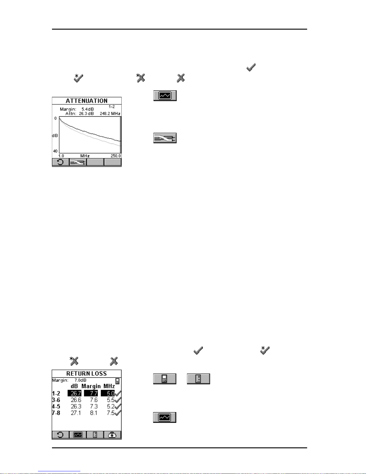
OMNIScanner User Guide
5 - 8
The pairs are displayed in the column on the left side, followed by the
Attenuation in decibels (dB), the Attenuation margin/limit values, and the
frequency . The result for each pair is tagged with a PASS , Marginal
PASS , Marginal FAIL , or FAIL indicator.
Press (Graph) to display the Attenuation
graph for the highlighted pair . The Attenuation is
displayed for the frequency indicated by the cursor
position.
Press (Pairs) to view Attenuation results for
other pairs.
Press ESC to exit the ATTENUATION screen.
Note: Attenuation always reports the worst dB value regardless of the
Report: setting in the RUN OPTIONS screen.
Return Loss
The Return Loss function measures the uniformity of a cable’s impedance.
OMNI
Scanner
injects a signal into the cable and measures the reflected
signal strength. Return Loss measures the difference between the transmitted signal delivered to the cable and the reflected signal at the input port of
the cable. The reflected signal is the result of impedance mismatches in the
link under test.
In the RETURN LOSS screen, the worst case margin for all near and far
pairs is shown at the top of the screen.
The pairs are displayed in the column on the left side, followed by the Return
Loss in decibels (dB), the Return Loss margin/limit, and the frequency . The
result for each pair is tagged with a PASS , Marginal PASS , Marginal
FAIL , or FAIL indicator .
Press or to toggle between the
Return Loss results for OMNI
Scanner
and
OMNI
Remote
.
Press (Graph) to display the Return Loss
graph for the highlighted pair . The Return Loss is
Page 69
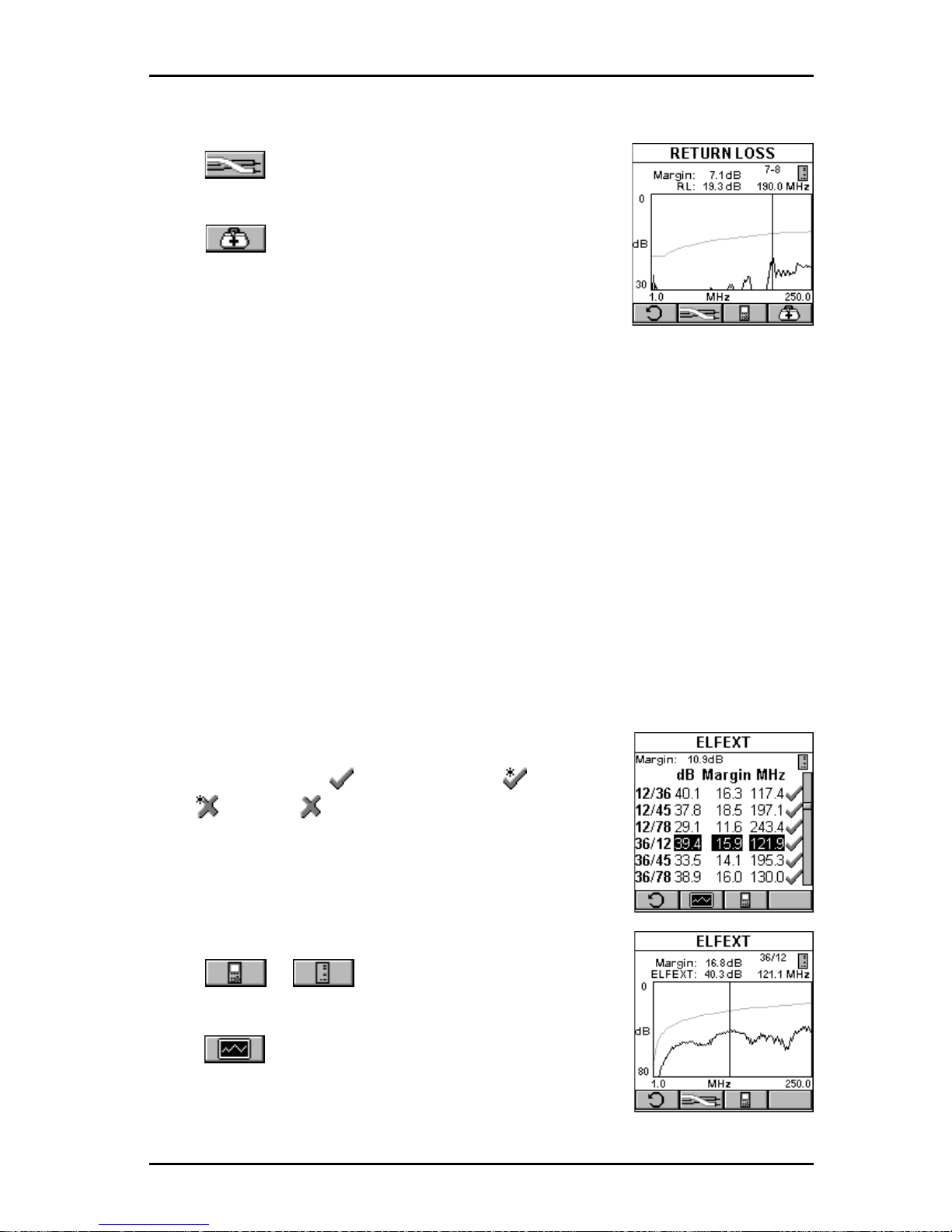
5 - 9
OMNIScanner User Guide
displayed for the frequency indicated by the cursor position.
Press (Pairs) to view Return Loss graphs for
other pairs.
Press (Diagnostics) to display the TDRL
screen, where cabling and/or connection faults can be
identified.
(See Chapter 6 - Diagnostics: Using TDRL
to diagnose a Link for further information.)
Press ESC to exit the RETURN LOSS screen.
ELFEXT
ELFEXT (Equal Level Far End Crosstalk) measures the electromagnetic
coupling at the far end and normalizes the result to account for the cable’s
attenuation. ELFEXT is reported in dB and results are computed for twelve
pair combinations at the OMNI
Scanner
and the OMNI
Remote
end of the
cabling.
In the ELFEXT screen, the worst case margin for all near and far pair
combinations is shown at the top of the screen.
The pair combinations are displayed in the column on the left side, followed
by the ELFEXT value, the margin/limit and the
frequency . The result for each pair combination is
tagged with a PASS , Marginal PASS , Marginal
FAIL , or FAIL indicator .
The scrollbar indicates that there are more test
results. Use the ê on OMNI
Scanner
’s keypad to
scroll through the list and view results for the other six
pair combinations.
Press or to toggle between the
ELFEXT results for OMNI
Scanner
and OMNI
Remote.
Press (Graph) to display the ELFEXT graph for
the currently highlighted pair combination. ELFEXT is
displayed for the frequency indicated by the cursor
position.
Page 70
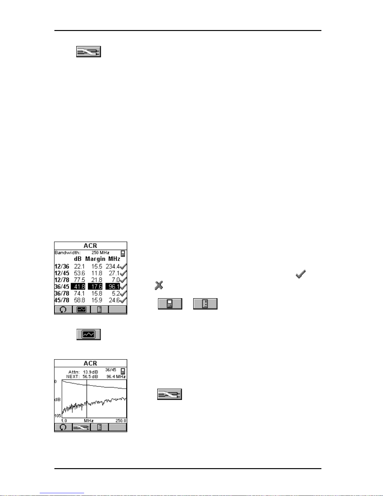
OMNIScanner User Guide
5 - 10
Press (Pairs) to view ELFEXT graphs for other pair combinations.
Press ESC to exit the ELFEXT screen.
ACR/Bandwidth
Attenuation to Crosstalk Ratio (ACR) is an indication of how much larger
the received signal is compared to the Near End Crosstalk (NEXT) on the
same pair . ACR is calculated from the measured NEXT and Attenuation. The
ACR value is computed at each measured Attenuation frequency . The worst
case ACR is reported for each pair combination.
Bandwidth is a measure of the usable frequency range of the link under test.
For most networks, this is the highest frequency at which the signal can
easily be distinguished from background noise. Bandwidth is reported as the
frequency where ACR is 3dB.
In the ACR screen the Bandwidth is displayed at the top of the screen.
The pair combinations are located in the column on
the left side, followed by the measured ACR, the
ACR margin/limit, and the frequency . The result for
each pair combination is tagged with a P ASS or
FAIL indicator.
Press or to toggle between ACR
results for OMNI
Scanner
and OMNI
Remote
.
Press (Graph) to view the graph for the currently highlighted pair
combination. The values for Attenuation and NEXT are shown at the top of
the screen. Attenuation and NEXT graphs are
displayed for the frequency indicated by the cursor
position.
Press (Pairs) to view Attenuation/NEXT
graphs for other pair combinations.
Press ESC to exit the ACR screen.
Page 71
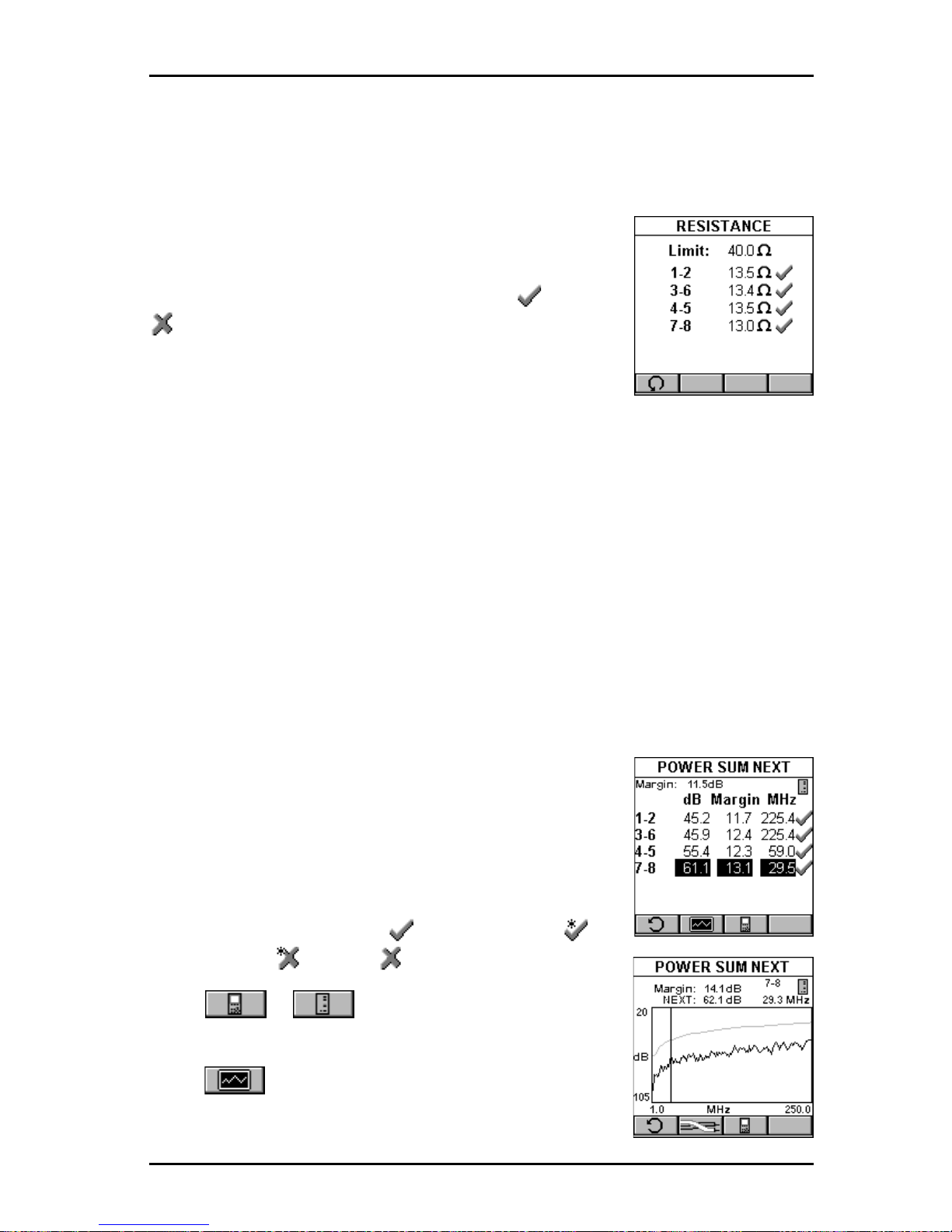
5 - 11
OMNIScanner User Guide
Resistance
Resistance is measured in a loop through each pair in the cable. In a
twisted pair cable, Resistance is measured by using OMNI
Remote
to short
the far end of the pair under test.
The RESISTANCE screen displays the Resistance
Limit and the test results in Ohms for each pair . The
result for each pair is tagged with a P ASS or FAIL
indicator.
Press ESC to exit the RESISTANCE screen.
Power Sum NEXT
Like NEXT , Power Sum NEXT is a measurement of electromagnetic
coupling between adjacent pairs. While NEXT reports test results for each
pair combination, Power Sum NEXT is calculated from NEXT for individual
pair combinations and takes into account the crosstalk from multiple
transmission pairs. When reporting Power Sum NEXT , OMNI
Scanner
displays results for pairs, rather than pair combinations. The PS NEXT
measurement is required to assure proper operation of networks employing
simultaneous transmission on more than one pair in a link (i.e. Gigabit
Ethernet).
In the POWER SUM NEXT screen, the worst case
margin for all near and far pairs is shown at the top of
the screen.
The pairs are displayed in the column on the left
side, followed by the PSNEXT in decibels (dB), the
margin/limit, and the frequency . The result for each
pair is tagged with a PASS , Marginal PASS ,
Marginal F AIL , or FAIL indicator.
Press or to toggle between the
PSNEXT results for OMNI-
Scanner
and OMNI
Remote
.
Press (Graph) to display the PSNEXT graph for
the currently highlighted pair . PSNEXT is displayed for
the frequency indicated by the cursor position.
Page 72
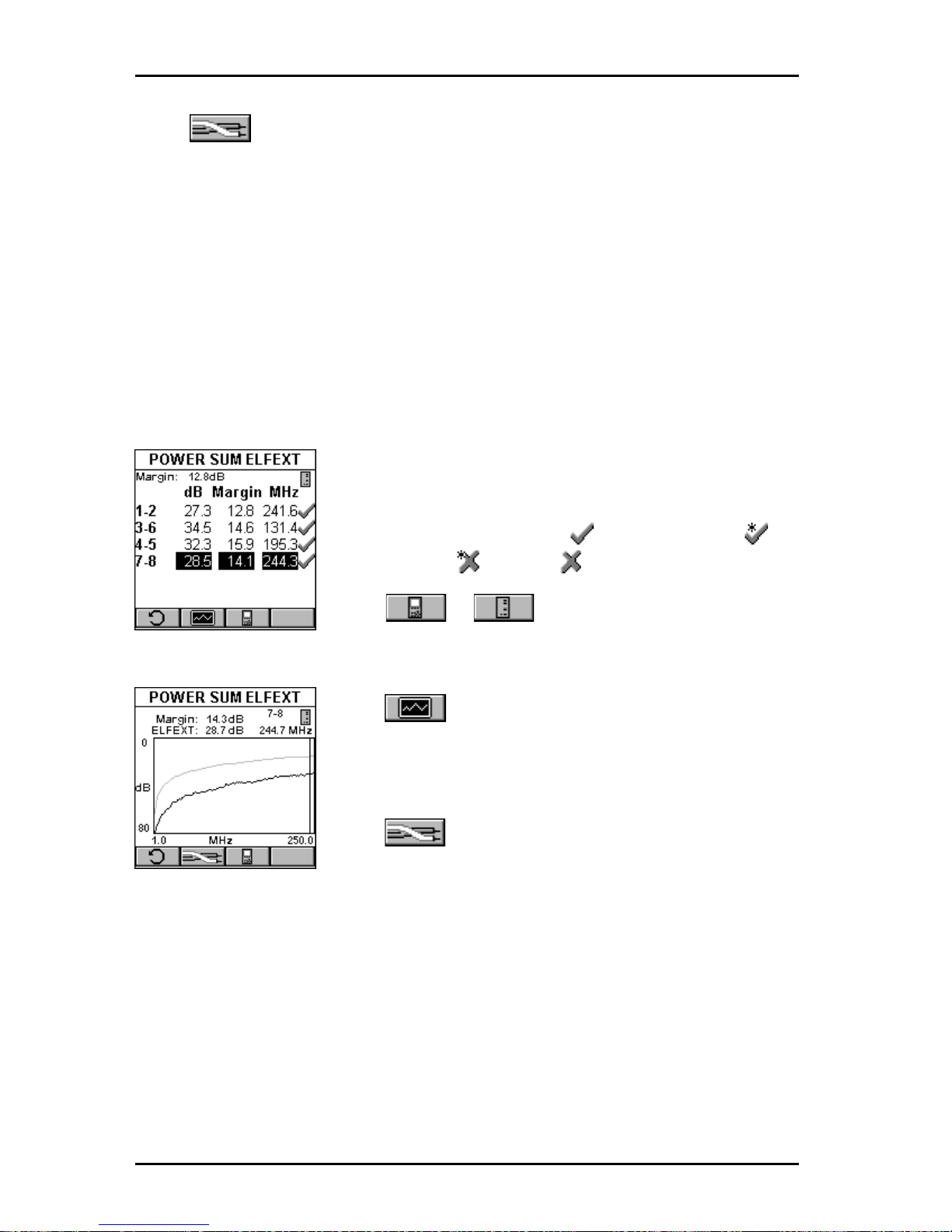
OMNIScanner User Guide
5 - 12
Press (Pairs) to view PSNEXT graphs for other pairs.
Press ESC to exit the POWER SUM NEXT screen.
Power Sum ELFEXT
Power Sum ELFEXT is calculated from the summation of the individual
ELFEXT effects on each pair by the other three pairs.
In the POWER SUM ELFEXT screen, the worst case margin for all near and
far pairs is shown at the top of the screen.
The pairs are displayed in the column on the left side,
followed by the PSELFEXT in decibels (dB), the
margin/limit, and the frequency . The result for each
pair is tagged with a PASS , Marginal PASS ,
Marginal F AIL , or FAIL indicator.
Press or to toggle between the
PSELFEXT results for OMNI
Scanner
and OMNI-
Remote
.
Press (Graph) to display the PSELFEXT graph
for the currently highlighted pair . PSELFEXT is
displayed for the frequency indicated by the cursor
position.
Press (Pairs) to view PSELFEXT graphs for
other pairs.
Press ESC to exit the POWER SUM ELFEXT screen.
Page 73
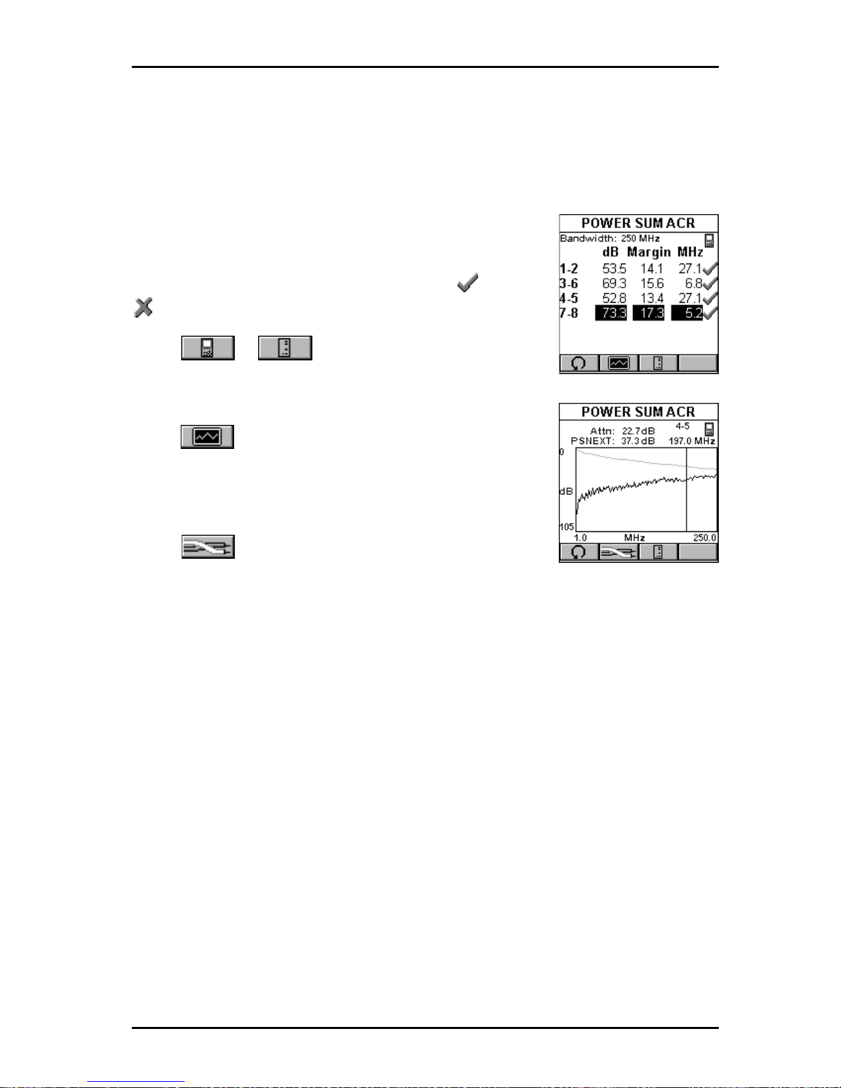
5 - 13
OMNIScanner User Guide
Power Sum ACR
Power Sum ACR is calculated from the Attenuation of the disturbing pair
subtracted from the Power Sum NEXT for the pair. The worst case Power
Sum ACR is reported for each pair.
The POWER SUM ACR screen displays the pairs in
the column on the left side, followed by the PSACR in
decibels (dB), the margin/limit, and the frequency . The
result for each pair is tagged with a P ASS or FAIL
indicator.
Press or to toggle between Power
Sum ACR results for OMNI
Scanner
and
OMNI
Remote
.
Press (Graph) to view the graph for the
currently highlighted pair . Attenuation and PSNEXT
are displayed for the frequency indicated by the
cursor position.
Press (Pairs) to view Attenuation and PS
NEXT graphs for other pairs.
Press ESC to exit the POWER SUM ACR screen.
Page 74
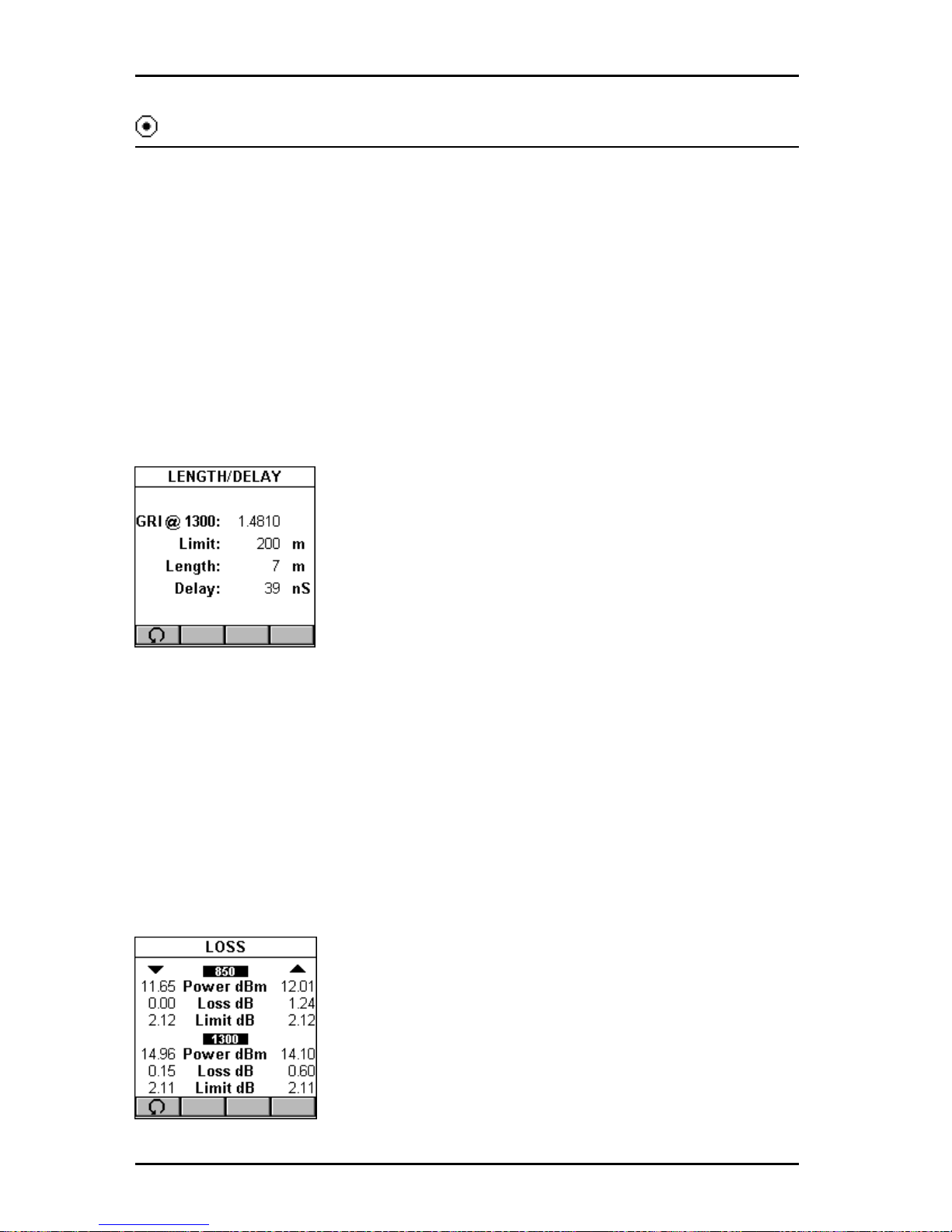
OMNIScanner User Guide
5 - 14
Fiber Optic Measurements with OMNIFiber
Length/Delay
The Length/Delay function measures a fiber’s length and propagation delay .
Length measurements are derived from the propagation delay results using
the GRI (Graded Refractive Index) at the appropriate wavelength.
Propagation Delay is the measure of the time required for a signal to advance from one end of the link to the other . When measuring propagation
delay , OMNI
Scanner
measures the round trip delay through both fibers, and
then divides the result by two, assuming that the cables are equal in length.
OMNI
Scanner
measures the full length of the fibers under test.
The LENGTH/DELAY screen displays the GRI @
1300 nm (nanometers) for multimode fiber and @
1310 nm for single-mode fiber.
The length limit and the actual derived length are
displayed in meters or feet.
The delay is displayed in nanoseconds (nS).
Press ESC to exit the LENGTH/DELAY screen.
Loss
The Loss function measures the signal loss in a fiber optic cable. The
adapters inject a signal into the fiber cable and OMNI
Scanner
and OMNI-
Remote
measure the received signals at 850 and 1300 nm for multimode
fiber and 1310 and 1550 for single-mode fiber.
The LOSS screen displays the measured power in dBm (decibels; one
milliwatt reference) for each wavelength.
The measured loss and limit values in decibel (dB)
are displayed for both wavelengths.
For dual fiber testing the arrows ▲▼ at the top of the
screen point out the direction of the light and indicate
which fiber the result is for.
Press ESC to exit the LOSS screen.
Page 75
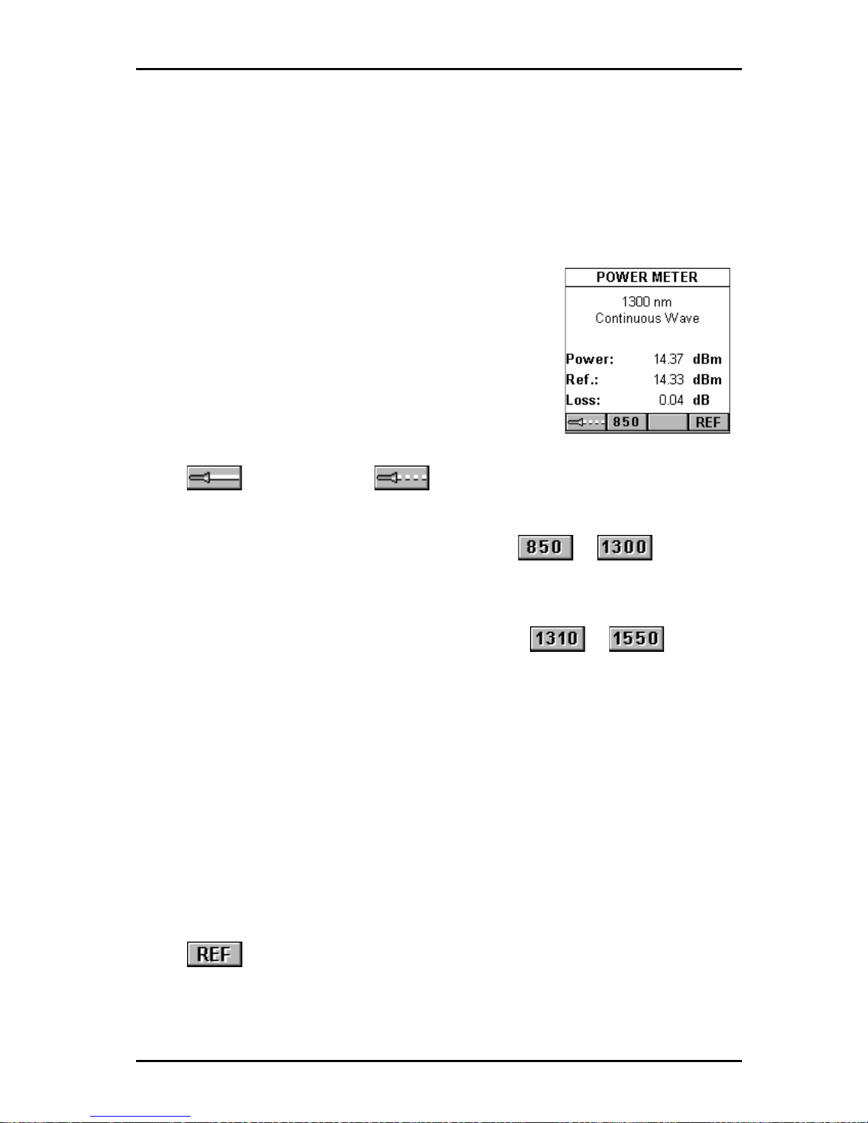
5 - 15
OMNIScanner User Guide
Power Meter
The Power Meter function reports the overall received power. Use it to
quickly verify and correct cabling and equipment problems.
The POWER METER screen shows the currently selected wavelength and
light source mode.
The overall power is displayed.
OMNI
Fiber
main is designed to provide a consistent, calibrated light source for effectively measuring
signal loss in fiber optic cables. The transmitted
light can be operated continuously or modulated.
When testing loss, use the continuous light source,
when identifying fiber cables with a tone locator , use
the 2KHz modulated mode.
Press (Continuous) or (Modulated) to change the light
source.
When using OMNIFiber MM (multimode), press or to change
the wavelength of the OMNIFiber Main transmitted and received wavelengths.
When using OMNIFiber SM (single-mode), press or to
change the wavelength of the OMNIFiber Main transmitted and received
wavelengths.
Either Main or Remote can be used as the light source with the main power
meter.
When OMNI
Fiber
is attached to OMNI
Remote
, the remote unit can be used
as light source. With the OMNI
Fiber
adapter attached, press the
λλ
λλ
λ key to
activate the light source and provide continuous or modulated light at 850 or
1300 nm for multimode fiber , or at 1310 or 1550 for single-mode fiber. The
green LED of the appropriate wavelength will blink rapidly when modulated
light is transmitted. If the transmitted light is continuous, the green LED will
not blink.
Press to set the reference value, place it in the appropriate field, and
start calculating the loss.
Press ESC to exit the POWER METER screen.
Page 76
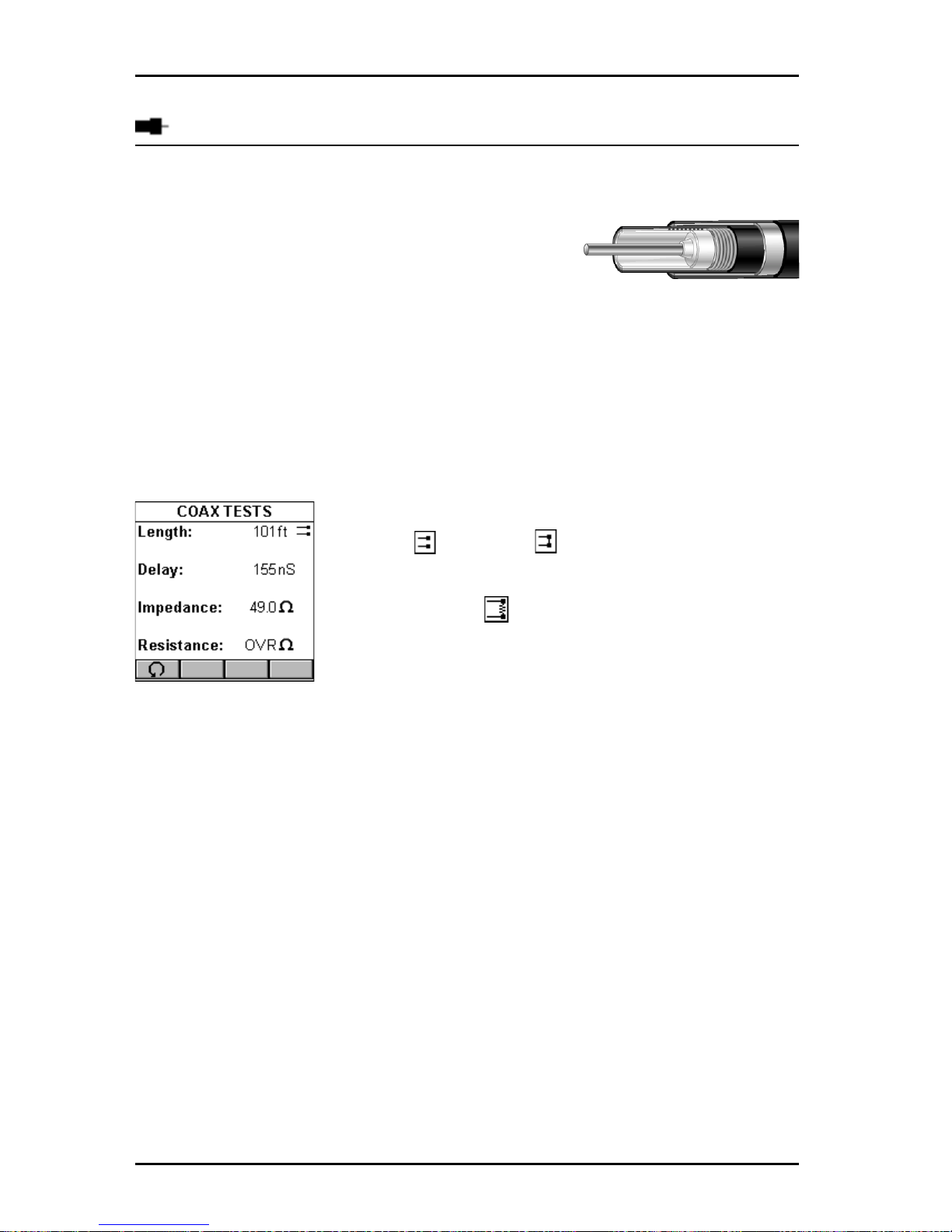
OMNIScanner User Guide
5 - 16
Coaxial Measurements with OMNIScanner
Coax Tests
In coaxial cable, an insulated wire runs through
the middle of the cable and a second wire, called
the shield, surrounds the insulation of the inner
wire like a sheath. The outer insulation jacket wraps around the second wire.
The Coax T ests screen displays the measured Length, T ermination, Imped-
ance, and Resistance.
The Length function measures the cable length. OMNI
Scanner
will display
the overall length in meters or feet. If NEF (No End Found) is displayed
instead of a value, the cable is either too long or terminated in its characteristic impedance.
The Termination function displays whether a cable
is open or shorted .
When the field Length: displays NEF , the Termination will display .
Impedance defines the relationship of voltage and
current in an electrical circuit.
Each Cable or transmission line is designed to have specific impedance,
which allows proper matching to the currents of the transmitter and receiver.
OMNI
Scanner
measures the characteristic impedance of the coax cable in
Ohms.
OMNI
Scanner
displays the Resistance in Ohms.
Tracer/Toner
Tracer/Toner is a cable tracing function that assists in tracking cables
hidden in walls, ceilings, floors, or patch panels by generating a signal that
can be converted into an audible tone by Microtest’s Cable Tracer II (sold
separately) or any other equivalent tracing device.
1. Attach the end of the cable you want to trace to the OMNIScanner using
a patch cord and the Microtest Channel Adapter or the Microtest Link
Adapter . Make sure that the cable is not grounded, as a grounded cable will
Page 77
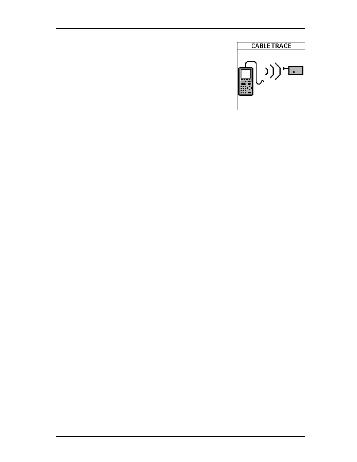
5 - 17
OMNIScanner User Guide
weaken the signal.
A multi-tone trace signal will begin transmitting. To
enhance the signal, insert a grounding plug into the
ground jack located left of the DB-9 Serial Connector .
A grounding plug is included in the optional Cable
Tracer II kit; you may use any grounding cable that
has a standard insulated phone tip plug.
2. To determine the cable path use the multi-tone sound as a guide and
simply trace along the wire where the tone is loudest. The tracer needs to
be within one foot of the hidden cable.
Press ESC to exit the CABLE TRACE screen.
Page 78

OMNIScanner User Guide
5 - 18
Page 79
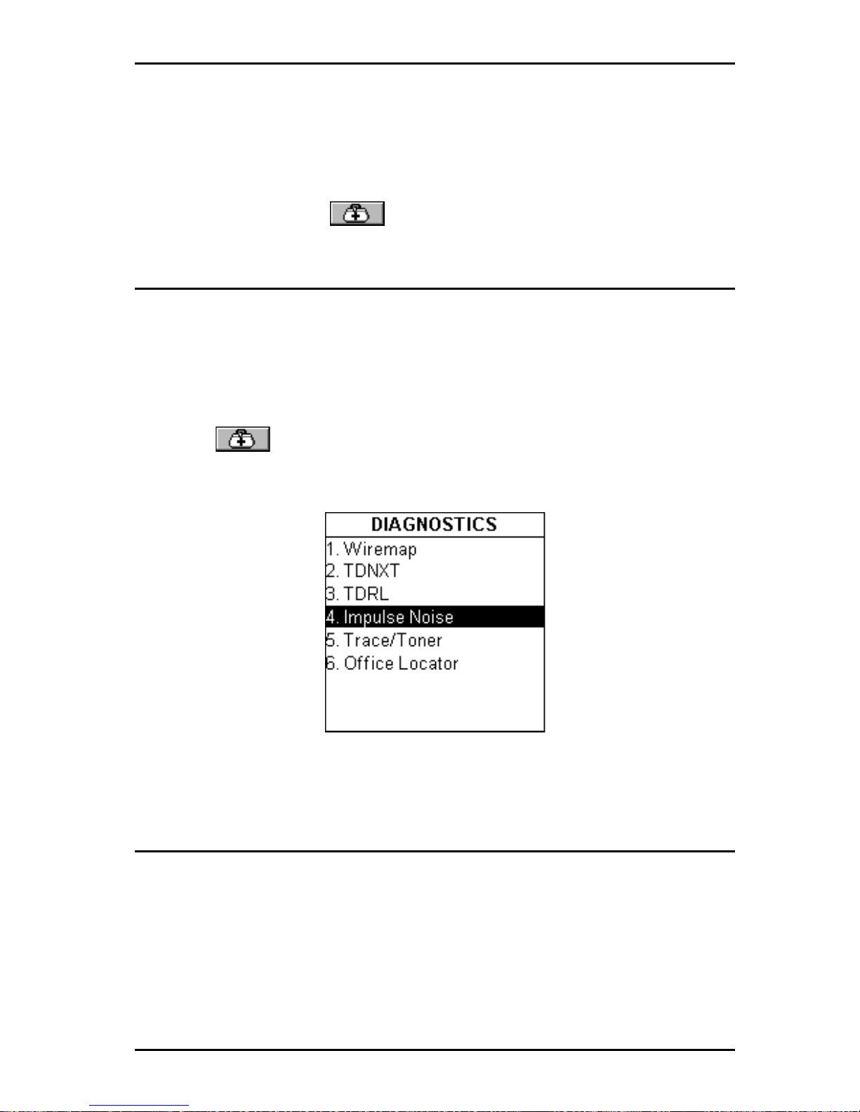
6 - 1
OMNIScanner User Guide
Chapter 6 - Diagnostics
OMNIScanner’s Diagnostic Functions
OMNI
Scanner
has several advanced diagnostic test functions to help you
with the identification of network cabling faults. Diagnostics allows you to
locate opens, breaks, and short circuits as well as NEXT and Return Loss
cabling faults in twisted pair cabling. Further , OMNIScanner allows you to
measure Impulse Noise, trace cables, and locate office drops.
Press the (Diagnostics) function key to display the DIAGNOSTICS
screen.
Wiremap
Wiremap identifies the location of opens, breaks and pairs that are shorted.
This allows quick identification of the fault location.
Select Wiremap to display the WIREMAP screen. The screen displays the
wire connections between OMNI
Scanner
and OMNI
Remote. The pairs that
are being tested are defined by the selected test standard.
Shield continuity
is tested if a shielded cable type is selected.
(See Chapter 4 - Setup:
Cables for further information about shielded cables.)
Page 80
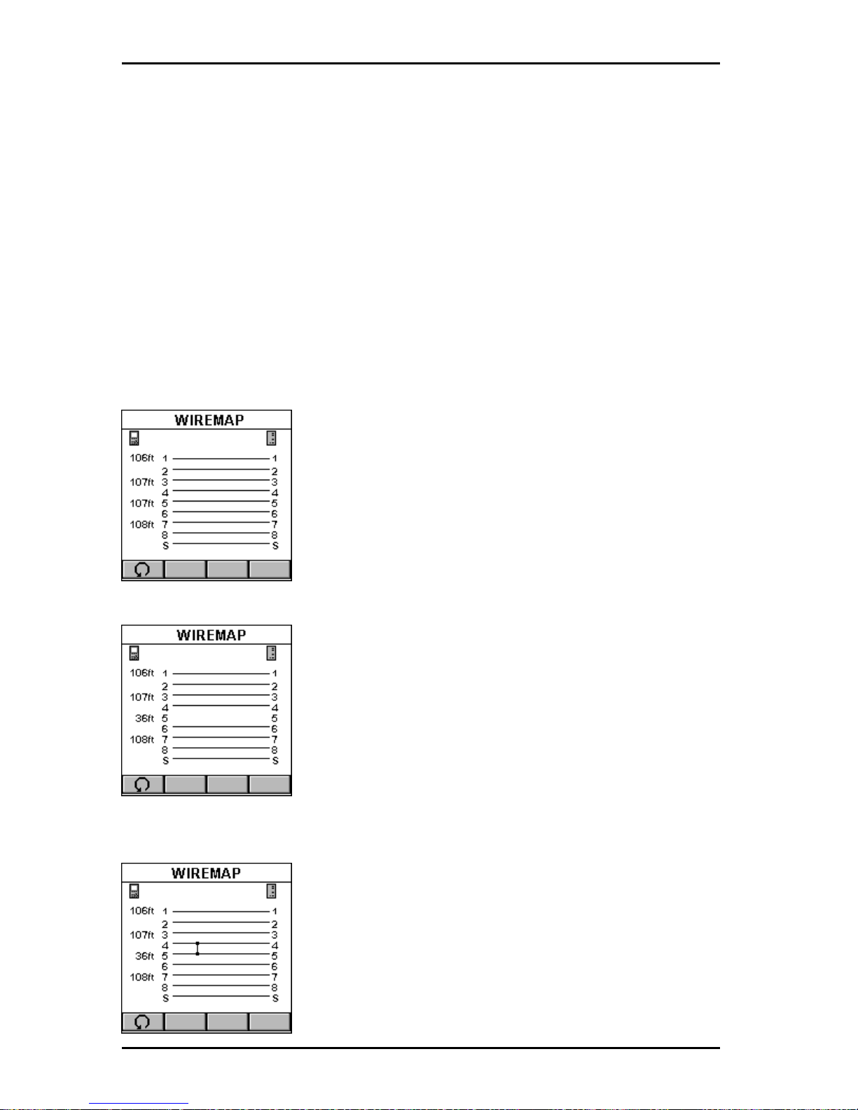
OMNIScanner User Guide
6 - 2
For each of the 8 conductors and the Shield, Wiremap can indicate proper
pin termination on each end, continuity to OMNI
Remote
, shorts between
any two or more conductors, crossed pairs, reversed pairs, split pairs, and
any other miswiring. For each pair , Wiremap displays the length. When a
pair is faulty the length indicates the distance to the fault from the
OMNIScanner end.
Wiremap Displays
The OMNI
Scanner
icon on the left side indicates the wiring at the OMNI
end of the cable link.
The OMNI
Remote
icon on the right side indicates the wiring at the OMNI-
Remote
end of the cable link.
CORRECT CONNECTIVITY:
The measured lengths of pairs 1-2, 3-6, 4-5, and 78 are shown on the left side of the Wiremap.
If the selected cable is shielded or screened, shield
continuity will be measured, and if the shield fails
the test, Wiremap will display the error .
WIRE IS OPEN:
Wiremap checks the continuity of each wire.
In this example, there is no line between pin 5 at
each end, which indicates a break in connection.
Use the number on the left side of the screen to find
the exact location of the open. For example if 36ft is
displayed, the open can be found 36ft away from
OMNI
Scanner
.
WIRES ARE SHORTED:
Wiremap finds shorts in the cable being tested.
In this example, the wiremap indicates that wires 4-
5 are shorted. Use the number on the left side of the
screen to find the exact location of the short. For
example if 36ft is displayed, the short can be found
36ft away from OMNI
Scanner
.
Page 81
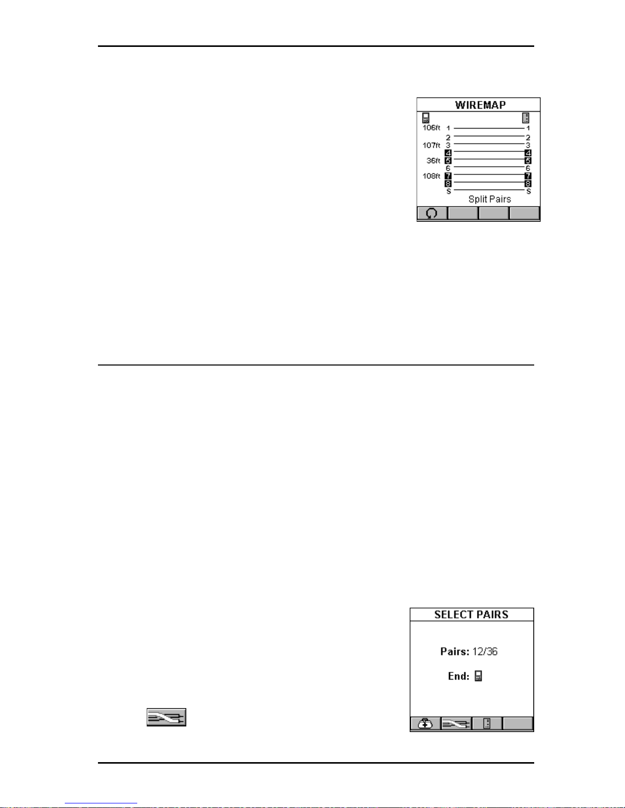
6 - 3
OMNIScanner User Guide
SPLIT PAIRS:
If a cable is wired correctly , pin-to-pin, but there is a
split pair , Wiremap displays Split Pairs and highlights
the pins in error .
In our example, one wire from the 4-5 pair is twisted
with one wire in the 7-8 pair . The Split Pair will be
highlighted with reversed numbers.
The message SPLIT PAIRS will be displayed below
the Wiremap.
Press ESC to exit the WIREMAP screen.
TDNXT
NEXT faults are diagnosed by using the TDNXT (Time Domain NEXT)
function. OMNI
Scanner
uses TDNXT to determine the amount of NEXT as
a function of distance. TDNXT with new S-Band™ technology (Standard
Connector Band technology) can help you distinguish between connection
and cable faults. It assists you with diagnosis and troubleshooting of NEXT
failures and the verification of test cables, connectors and plugs.
While the NEXT graph shows the link test limits and the frequency at which
a failure occurred, the TDNXT graph displays NEXT vs. distance.
S-Bands™ provide a time domain limit to verify that the connections are
within the desired category of performance. In a typical link, failures are a
result of either a non-compliant connection or a faulty cable. The ability to
determine if a connection meets the expected performance requirement
significantly simplifies the diagnosis of a failure.
To diagnose a failure, select TDNXT in the DIAGNOSTICS screen and press ENTER. The TDNXT
function is also available from the NEXT Graph
screen.
The SELECT PAIRS screen opens.
Use the (Pair) function key to select the pairs
you want to analyze.
Page 82
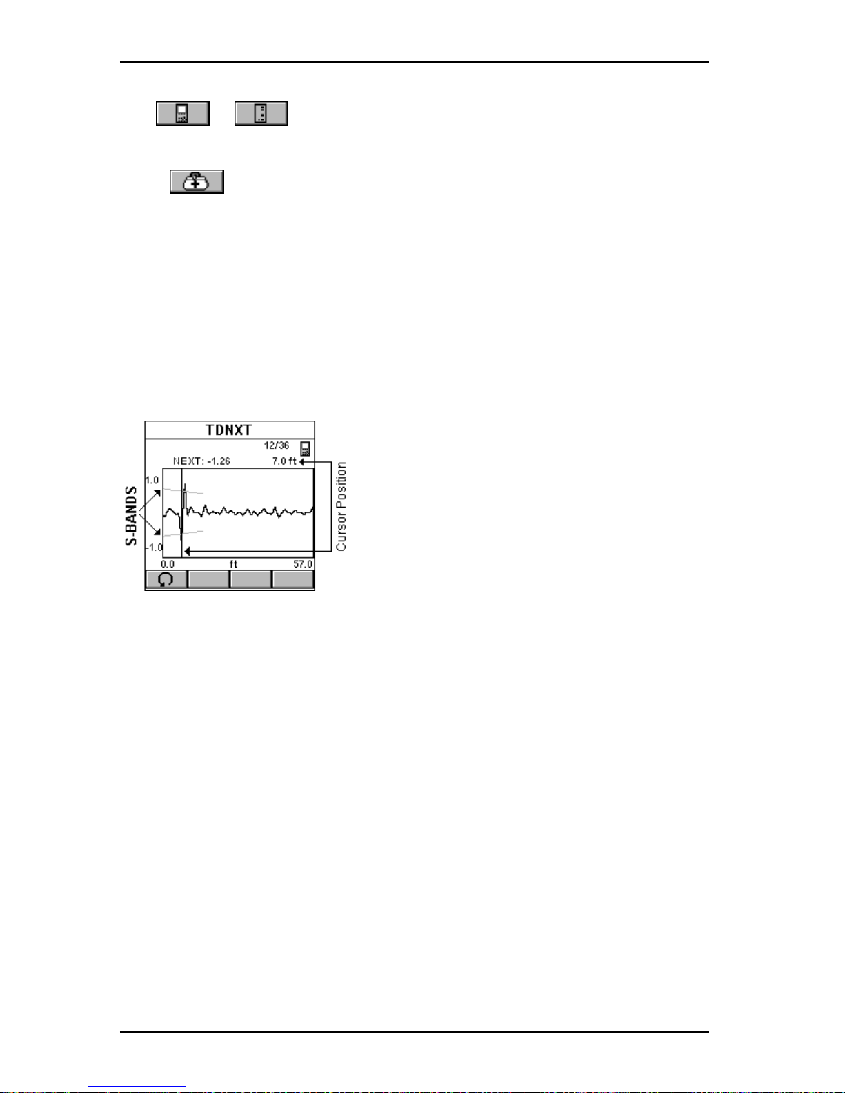
OMNIScanner User Guide
6 - 4
Use or to select which end, OMNI
Scanner
or OMNI
Remote,
you want to view the results for.
Press to open the TDNXT screen.
The screen displays the TDNXT (Time Domain NEXT) graph. The funnel-
like lines are the upper and lower S-Bands. S-Bands are limit lines for
connections as a function of distance from the cable end. They provide a
quantitative measure of the NEXT at the connection point, which is typically
located at the end of the test cable at 2 meters (7ft). The measurement unit
for the horizontal graph can be displayed in meters (m) or feet (ft.).
(See
Chapter 4 - Setup: User Options for further information about units.)
Initially , the cursor is located at the point with the worst NEXT.
The NEXT at the cursor position relative to
the S-Band, the corresponding pair
combination, and the distance to the
cursor position are displayed above the
graph.
The example shows a Time Domain
NEXT that exceeds the S-Bands. The
worst NEXT is displayed at 7ft, the connection location. The conclusion is that the
connection caused the failure.
Press ESC to exit the TDNXT screen.
Using TDNXT to Diagnose a Link
The S-Band limit lines provide an easy method to pinpoint faults located at
the connection or the cable. S-Bands allow you to determine if the connections in a link meet the desired performance level. They are designed to
match the standard category of the selected Autotest.
A graph containing peaks that are located outside the S-bands at the
connection distance indicates that the connection and not the installed
cable is the most likely reason for failure.
If NEXT failed but the TDNXT graph displays peaks within the S-Bands at
the connection distance, the fault is caused by the cable portion of the link.
Page 83
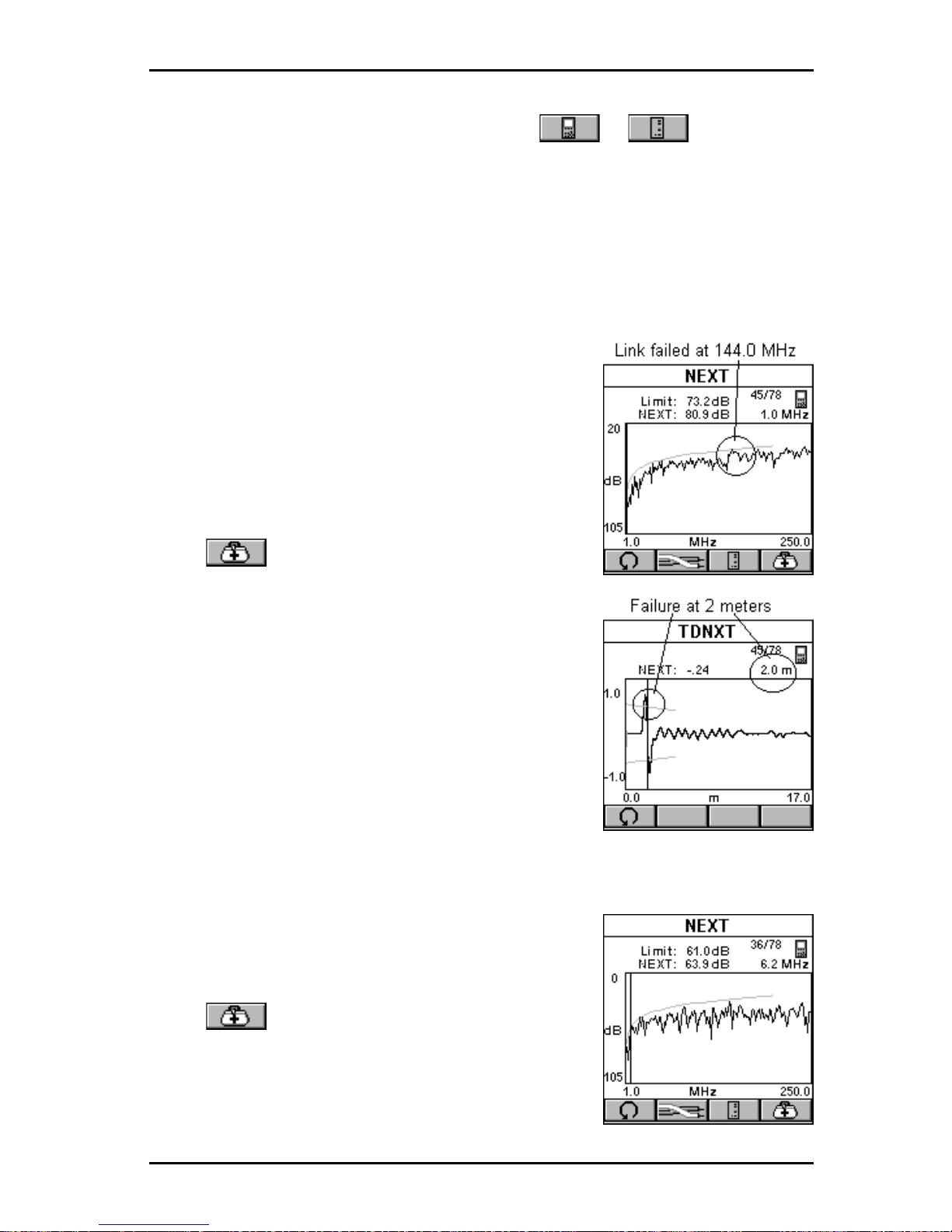
6 - 5
OMNIScanner User Guide
If failures occur at both ends of the link, use or to diagnose
each end. Failures at both ends of the link can interact.
TDNXT Examples
The following examples show the diagnostics process that is performed to
identify failures on typical links with 2 meter test cables.
GOOD CABLE, BAD CONNECTION:
The cursor in the NEXT graph is located at the
worst NEXT at 144.0 MHz, which is outside the
limit line. (For display purposes the cursor is
moved.) The Link failed. Why?
Press to open the TDNXT screen to
further review and diagnose the graph.
The cursor is positioned at the worst peak, which
is outside the S-Bands.
Looking at the TDNXT graph we can reach the
conclusion that the connection located at 2
meters did not meet the required performance
and is the cause of failure.
BAD CABLE, GOOD CONNECTION:
The cursor in the NEXT graph is located at the
worst NEXT at 6.2 MHz, which is outside the limit
line. (For display purposes the cursor is moved to
the Zero-position.) The Link failed. Why?
Press to open the TDNXT screen to
further review and diagnose the graph.
The NEXT response from the connector located
at 2 m is well within the S-Bands and performs
significantly better than the requirements. The
Page 84
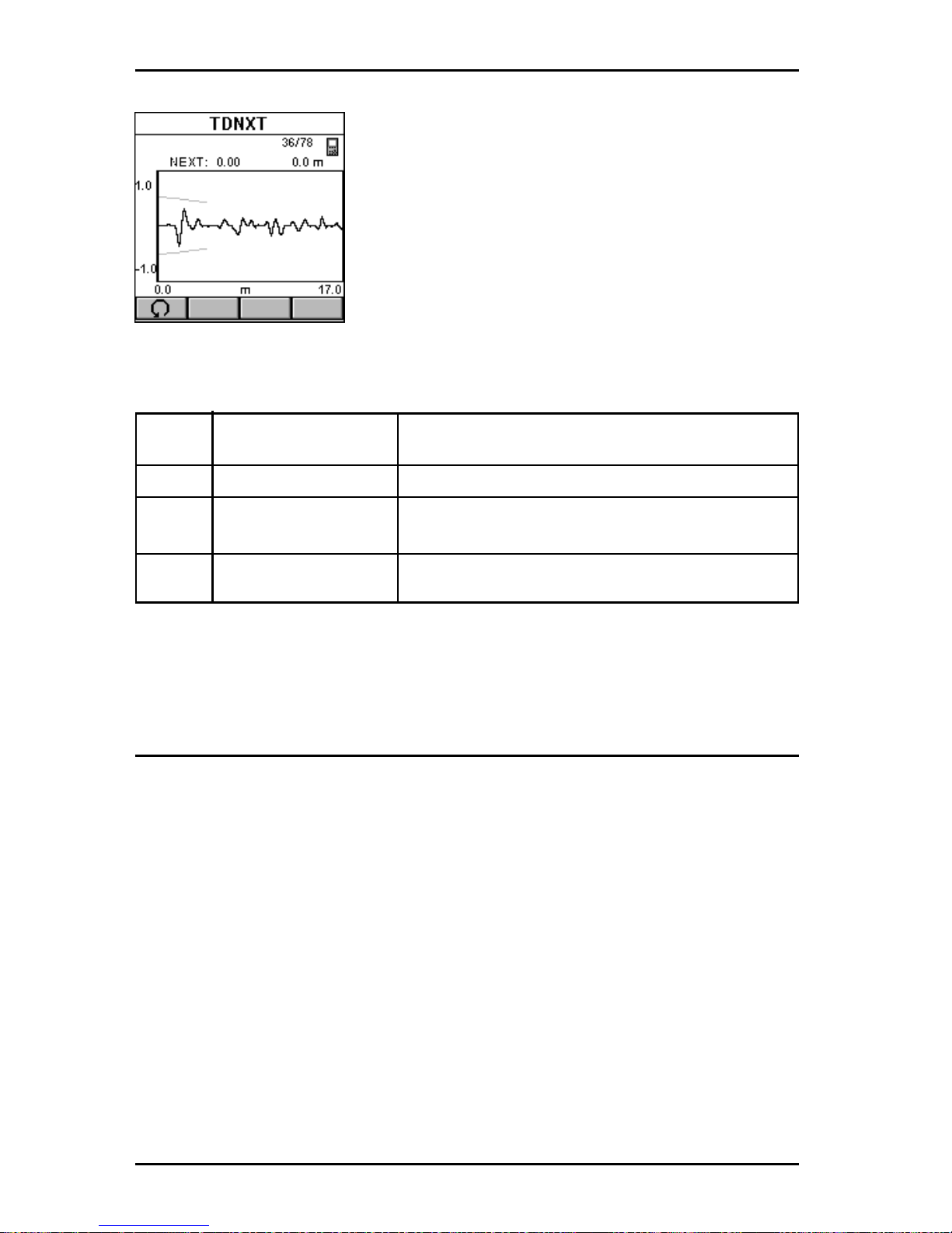
OMNIScanner User Guide
6 - 6
NEXT in the cable is the source of the failure
even though the cable’s NEXT response peaks
are less than those of the connection. By
knowing that the connection meets its performance requirement, the cable is easily identified as the non-compliant component of the
link.
The following table summarizes the typical
diagnosis process.
NEXT TDNXT exceeds Conclusion
S-Band limits
P ASS N/A NEXT of link is within limits
FAIL YES Connection fails. Replace or reterminate.
Plug and/or jack can be at fault.
FAIL NO Cable is not within specifications
TDRL
Return Loss is a measure of the amount of reflected energy in a link.
Reflections occur at points of impedance discontinuity , such as connectors,
transitions from patch cables to horizontal cables, and impedance structure
within a cable.
Return Loss faults are diagnosed by using the TDRL (Time Domain Return
Loss) function. OMNI
Scanner
uses TDRL to determine the amount of
Return Loss as a function of distance. TDRL with new S-Band™ technology (Standard Connector Band technology) can help you to distinguish
between connection faults and cable faults. It assists you with diagnosis
and troubleshooting of Return Loss failures and the verification of test
cables, connectors and plugs.
While the Return Loss graph shows the link test limits and the frequency at
which a failure occurred, the TDRL graph displays Return Loss vs. distance.
Page 85
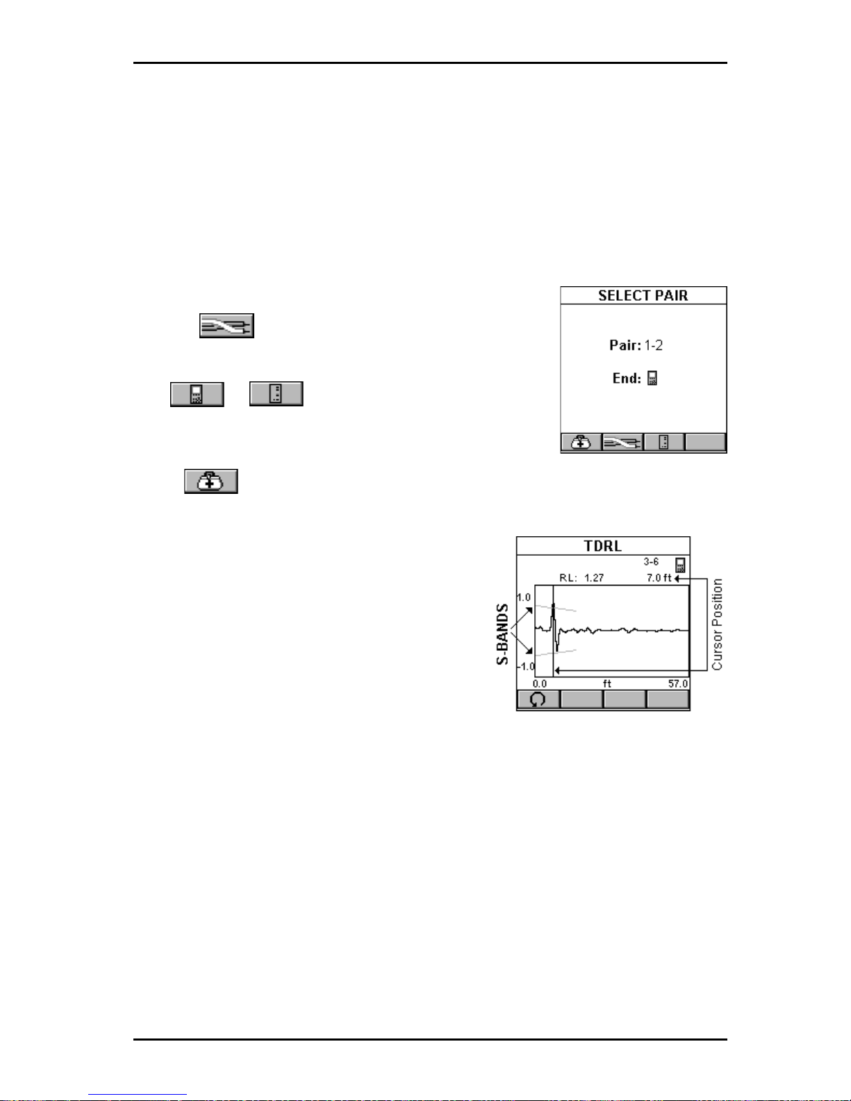
6 - 7
OMNIScanner User Guide
S-Bands™ provide a time domain limit to verify that the connections are
within the desired category of performance. In a typical link, failures are a
result of either a non-compliant connection or a faulty cable. The ability to
determine if a connection meets the expected performance requirement
significantly simplifies the diagnosis of a failure.
Select TDRL in the DIAGNOSTICS screen and press ENTER. The TDRL
function is also available from the RETURN LOSS Graph screen.
The SELECT PAIR screen opens.
Use the (Pair) function key to select the Pair
you want to analyze.
Use or to select which end, OMNI-
Scanner
or OMNI
Remote,
you want to view the
results for .
Press to open the TDRL screen
The screen displays the TDRL (Time
Domain Return Loss) graph. The funnellike lines are the upper and lower SBands. S-Bands are limit lines for connections as a function of distance from the
cable end. They provide a quantitative
measure of Return Loss at the connection
point, which is typically located at the end
of the test cable, at about 2 meters (7ft).
The measurement unit for the horizontal
graph can be displayed in meters (m) or feet (ft.).
Initially , the cursor is located at the point with the worst Return Loss.
The Return Loss at the cursor position, the corresponding pair, and the
distance to the cursor position are displayed above the graph.
The example shows a Time Domain Return Loss that exceeds the S-
Bands. The worst Return Loss is displayed at 7ft, the connection. The
conclusion is that the reflection at the connection is the cause of the failure.
This could be due to a connector problem or excessively untwisted pairs at
the connector.
Press ESC to exit the TDRL screen.
Page 86
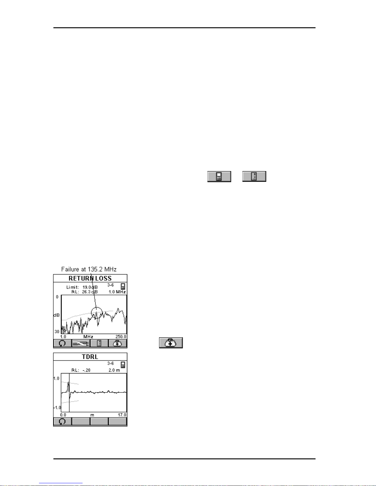
OMNIScanner User Guide
6 - 8
Using TDRL to Diagnose a Link
S-Bands provide an easy method to pinpoint if the fault is located at the
connection or at the cable. The S-Bands allow you to determine if the
connections in a link meet the desired performance level. They are designed to match the standard category of the selected Autotest.
A graph containing peaks that are located outside the S-Band at the
connection distance indicates that the connection and not the installed
cable failed.
If Return Loss fails but the TDRL graph displays peaks within the S-Band
at the connection distance, the fault is caused by the cable portion of the
link.
If failures occur at both ends of the link, use or to diagnose
each end. Failures at both ends of the link can interact.
TDRL Examples
The following examples show the diagnostics process that is performed to
identify failures on typical links with 2 meter test cables.
GOOD CABLE, BAD CONNECTION:
The cursor in the Return Loss graph is located at
the worst Return Loss at 135.2 MHz, which is
outside the limit line. (For display purposes the
cursor was moved.) The Link failed. Why?
Press to open the TDRL screen to further
review and diagnose the graph.
The cursor is positioned at the worst peak, which is
outside the S-Bands.
Looking at the TDRL graph we can reach the
conclusion that the connection located at 2 meters
did not meet the required performance and is the
cause of failure.
Page 87
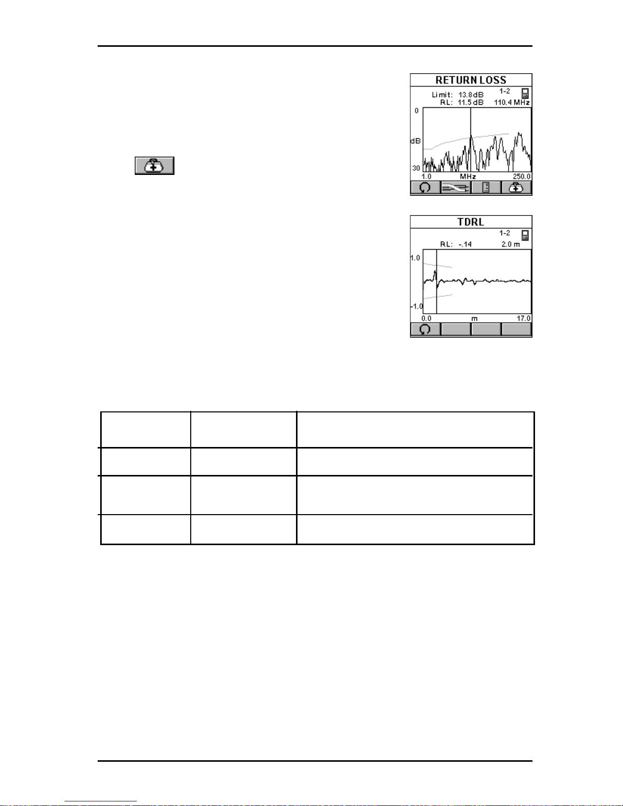
6 - 9
OMNIScanner User Guide
BAD CABLE, GOOD CONNECTION:
The cursor in the Return Loss graph is located at the
worst Return Loss at 1 10.4 MHz, which is outside
the limit line. The Link failed. Why?
Press to open the TDRL screen to further
review and diagnose the graph.
The Return Loss response from the connector
located at 2 m is well within the S-Bands and
performs significantly better than the requirements.
The Return Loss in the cable is the source of the
failure even though the cable’s Return Loss response peaks are less than those of the connection.
By knowing that the connection meets its performance requirement, the cable is easily identified as
the non-compliant component of the link.
The following table summarizes the typical diagnosis process.
Return Loss TDRL exceeds Conclusion
S-Band limits
P ASS N/A Return Loss of link is within limits
FAIL YES Connection fails. Replace or reterminate.
Plug and/or jack can be at fault.
FAIL N O Cable is not within specifications
Page 88
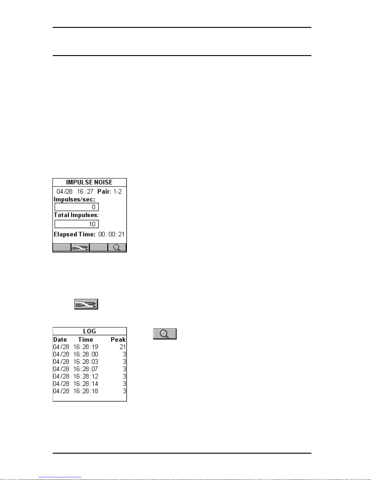
OMNIScanner User Guide
6 - 10
Impulse Noise
Noise is undesirable electrical energy that falls within the typical network
frequency bands of operation (generally 1-20 Mhz). It interferes with a
network’s ability to transmit data reliably. Noise sources may include AC
transmission lines, fluorescent light fixtures, industrial equipment, elevators, etc. Noise problems also occur when other wire pairs in the same
sheath are used for non-LAN applications.
Testing for noise involves turning off all LAN devices and measuring for
background electrical activity in the cabling. Often, noise problems can be
corrected by moving the cable away from the source or by removing the
source itself.
Impulse Noise counts the impulses detected on a given pair
Select Impulse Noise to open the IMPULSE NOISE
screen. The current date and time is shown in the
upper left. The monitored pair is shown in the upper
right.
Impulses/sec indicates the number of wide band
impulses that exceed 30 mv peak-to-peak that were
detected in the last 1second interval.
Total Impulses indicates the total number of impulses detected since noise
monitoring was started.
Elapsed Time indicates the time since the test was started.
Press (Pair) to clear the current log and monitor impulse noise on
another pair .
Press (Detail) to open the LOG screen.
OMNIScanner keeps a log during impulse noise
monitoring. The log represents the seven largest
impulse noise counts detected and the date and
times at which they occurred.
Press ESC to exit the LOG screen.
Press ESC to exit the IMPULSE NOISE screen.
Page 89
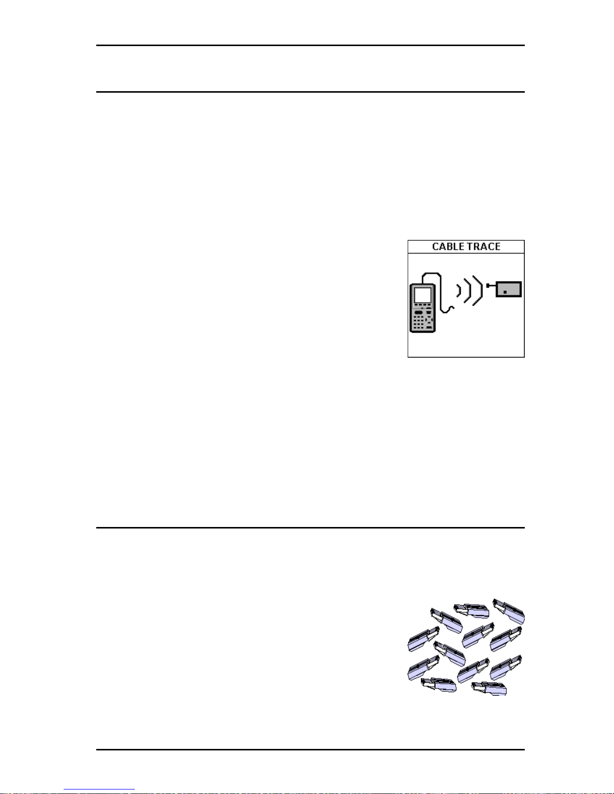
6 - 11
OMNIScanner User Guide
Cable Trace
Tracer/Toner is a cable tracing function that assists in tracking cables
hidden in walls, ceilings, floors, or patch panels by generating a signal that
can be converted into an audible tone by Microtest’s Cable T racer II (sold
separately) or any other equivalent tracing device.
1. Attach the end of the cable you want to trace to the OMNIScanner using
a patch cord and the Microtest Channel Adapter or the Microtest Link
Adapter . Make sure that the cable is not grounded, as a grounded cable will
weaken the signal.
A multi-tone trace signal will begin transmitting. To
enhance the signal, insert a grounding plug into the
ground jack located left of the DB-9 Serial Connector. A grounding plug is included in the optional
Cable Tracer II kit; you may use any grounding
cable that has a standard insulated phone tip plug.
2. To determine the cable path use the multi-tone
sound as a guide and simply trace along the wire
where the tone is loudest. The tracer needs to be within one foot of the
hidden cable.
Press ESC to exit the CABLE TRACE screen.
Office Locator
The Office Locator function allows you to find the termination of an office
cable drop from a wiring closet. It eliminates the need to trace cables
through walls and ceilings.
1. Connect the cable to be tested to OMNI
Scanner
.
2. Insert the RJ-45 Office Locator adapters into wall
outlets in the offices you wish to identify. Y ou can
connect any or all of the twelve Office Locators
before beginning your test.
3. At the patch panel, run the Office Locator function
to identify, which office is connected to a given port.
Page 90
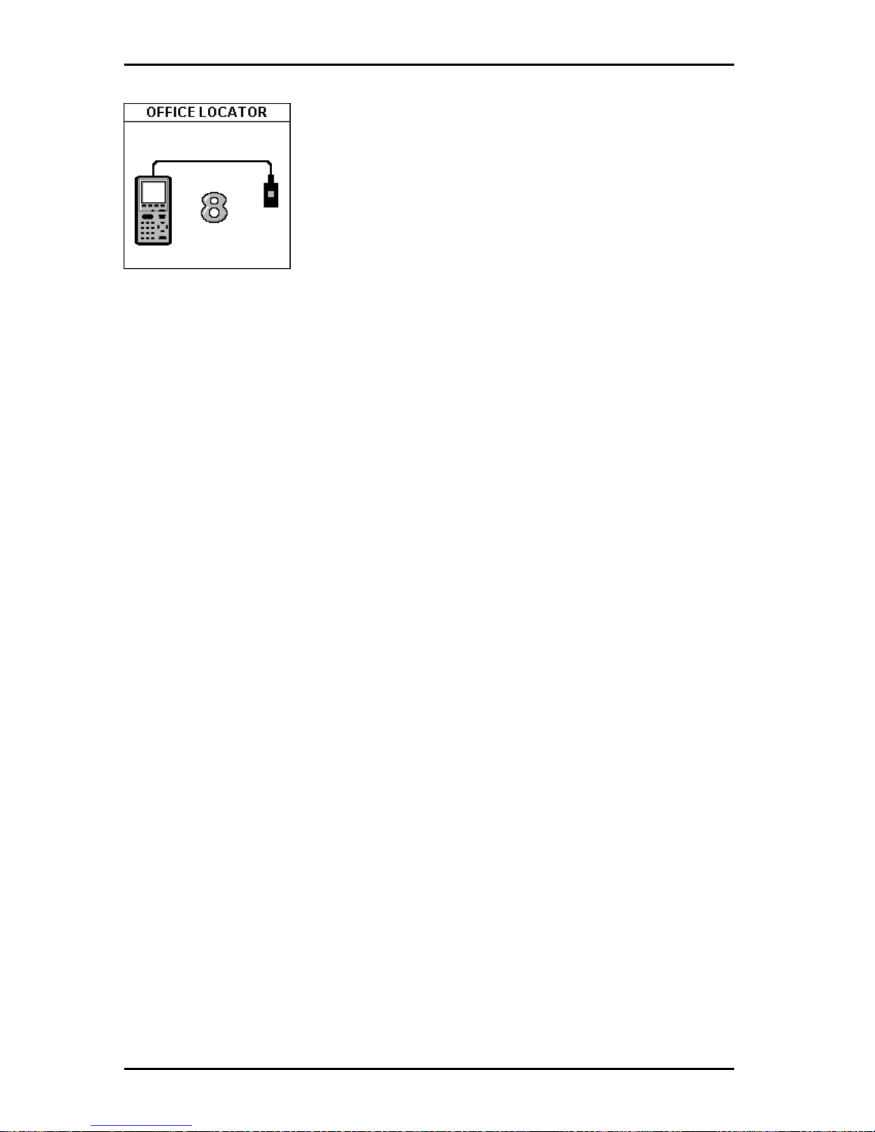
OMNIScanner User Guide
6 - 12
OMNI
Scanner
will identify office locations and
display the ID of the Office Locator adapter found at
the far end of the attached cable.
If you are testing a cable that does not have an
Office Locator attached at the other end, OMNI-
Scanner
will display a question mark.
Press ESC to exit the OFFICE LOCATOR screen.
Page 91
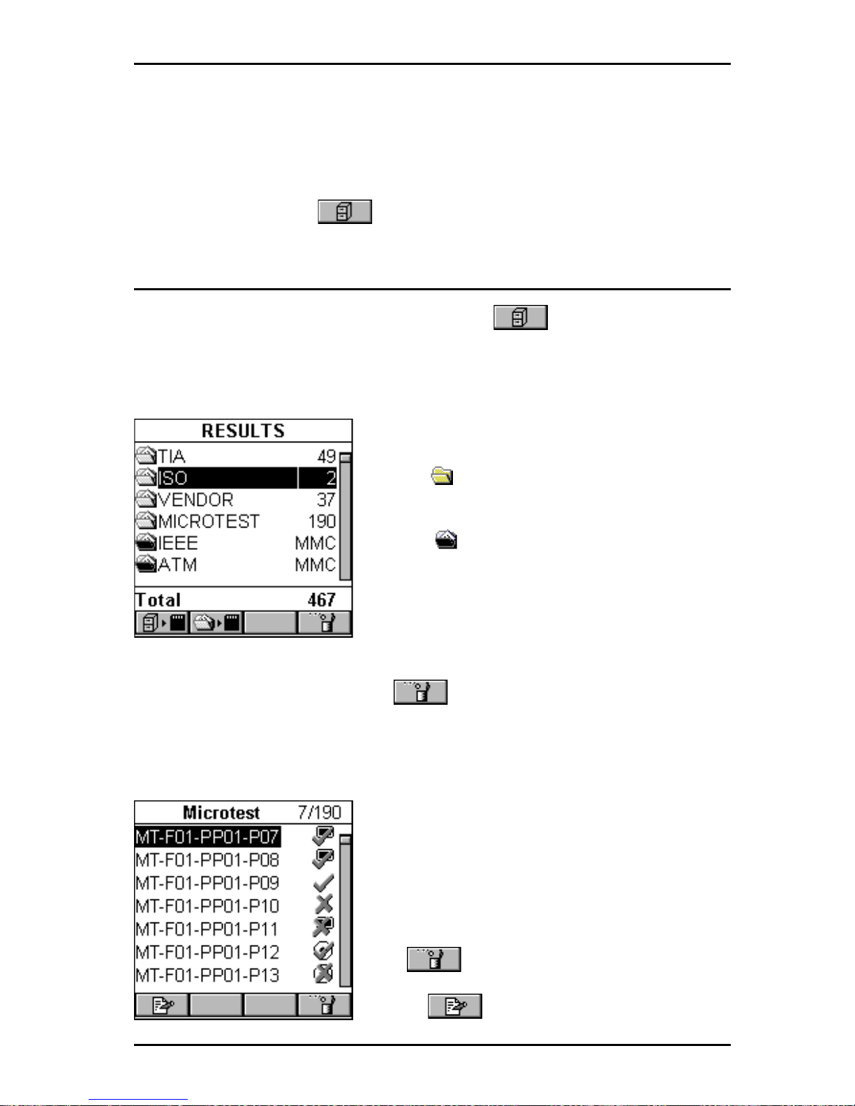
7 - 1
OMNIScanner User Guide
Chapter 7 - Results
Autotest Results
T o view previously saved Autotests, press the (Results) function key .
The RESULTS screen displays Project names together with the number of
Autotests that are stored within each project. In the bottom row you will find
the total number of Autotests currently stored in OMNI
Scanner
’s memory.
Light Project folders identify internally
stored results.
Black Project folders identify results
stored on MMC.
(See Chapter 11 -
MultiMediaCard for further information.)
To quickly remove all Autotests from a project, highlight the project in the
RESULTS screen and press the (Delete) function key . A message
will prompt you to confirm the operation.
T o view more detailed test information, highlight a project name and press
ENTER.
The previously highlighted PROJECT
NAME will now appear in the title bar
together with a numeric test counter that
shows the number of Autotest results stored
within the project.
To remove an Autotest from the list, press
the (Delete) function key .
Press (Edit) to move the Autotest to
Page 92
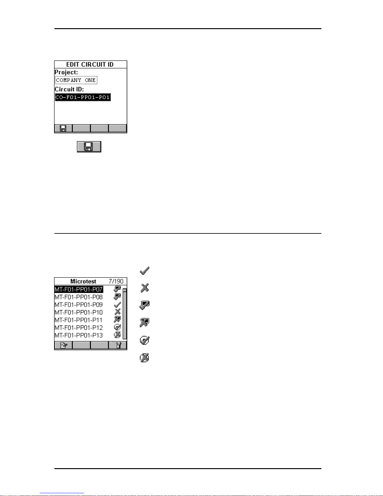
OMNIScanner User Guide
7 - 2
another project or to change the Circuit ID.
Press ENTER with the Project: highlighted to reveal a
list of all projects that are currently stored. Use the
éê to highlight the project you want to store the
Autotest within, and press ENTER to select it.
Use the ê to highlight the Circuit ID: and press
ENTER to edit the field. Press ENTER to terminate
the edit mode.
Press (Save) to save the changes and return to the PROJECT
NAME screen. If the PROJECT NAME was changed, it will now appear in
the title bar together with the numeric test counter.
Viewing Autotest Results
The Project Name screen shows a Circuit ID and a PASS/FAIL icon for
each saved Autotest. The following P ASS/FAIL icons can be displayed:
Passed twisted pair Autotest.
Failed twisted pair Autotest.
Passed twisted pair Autotest with graphs.
Failed twisted pair Autotest with graphs.
Passed fiber Autotest.
Failed fiber Autotest.
To view detailed information about a saved Autotest use the éê on your
keypad to highlight a Circuit ID in the Project Name screen and press
ENTER.
Page 93
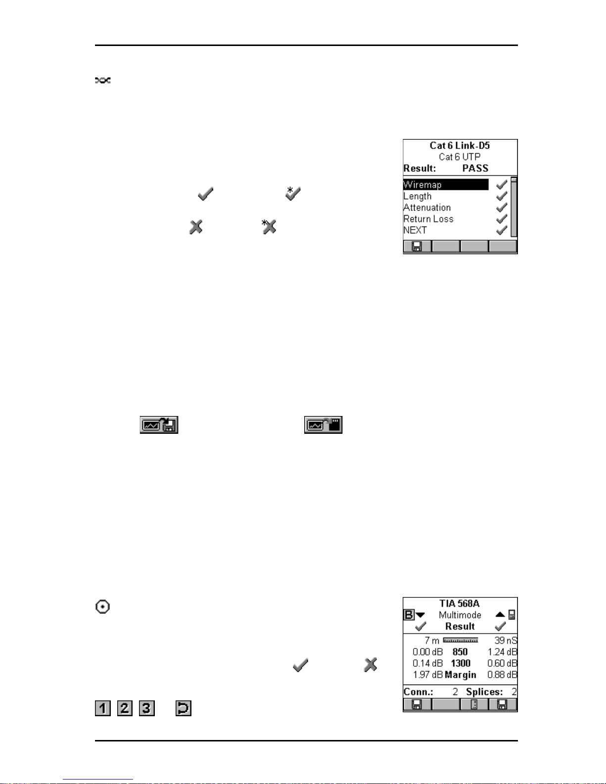
7 - 3
OMNIScanner User Guide
For Twisted Pair Cabling:
The Autotest Results screen will be displayed. The name of the Autotest,
the cable that was used to run the test, and the overall test result (P ASS or
F AIL) are shown.
All measurements that were performed during the
Autotest are listed in the left column. Passed tests
are marked with a (PASS) or a (Marginal
PASS). If a test result did not pass, the test name will
be followed by a (Fail) or a (Marginal F AIL)
symbol.
Note: The list of tests varies depending on the kind of Autotest that was
performed.
(See Chapter 5 - Measurements for detailed information about each measurement screen.)
Use the éê on your keypad to highlight a test.
Press ENTER to open the test result screen for that particular test.
Use the ç or è on your keypad to quickly page through all test results.
Note: If (Save with Graphs) or (Save with Graphs to MMC)
was selected when saving the Autotest, graphs associated with NEXT ,
Attenuation, Return Loss, PSNEXT, ELFEXT , ACR, PSELFEXT, and/or
PSACR are available when viewing Autotest results. Only the graphs that
were selected in the SA VE OPTIONS screen will be saved. (See Chapter 4 Setup: Save Options for information about selecting graphs to be saved.)
Press ESC to return to the PROJECT NAME screen.
Press ESC to return to the RESULTS screen.
For Fiber Optic Cabling:
The Autotest Results screen will be displayed. The
name of the Autotest, the cable that was used to run
the test, and the overall test result ( P ASS or
F AIL) for both fibers are shown.
, , , or (Loopback) are displayed to
Page 94
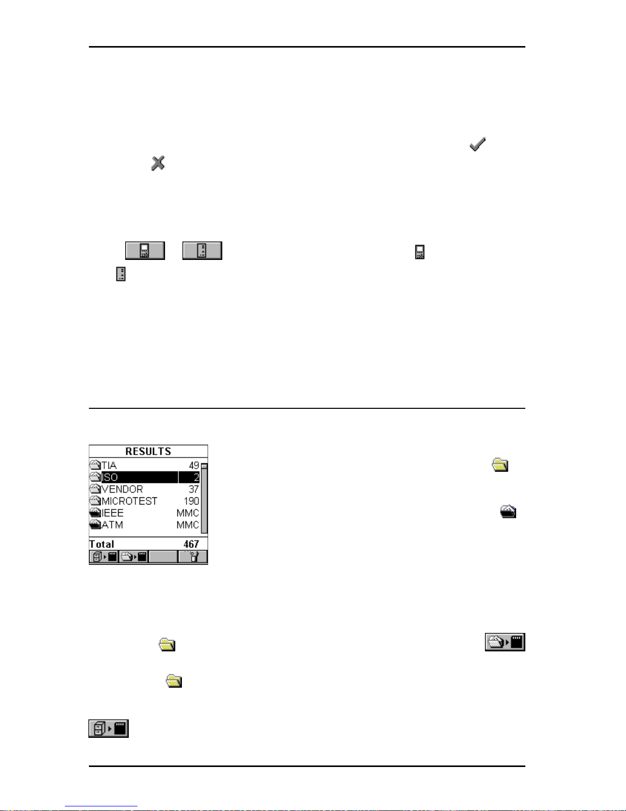
OMNIScanner User Guide
7 - 4
indicate the Method used to set the reference.
(See Chapter 8 - Fiber Optic
Reference for further information.)
When dual fiber is measured, arrows ▲▼ at the top of the screen point out
the direction of the light. The arrows also indicate the fiber that the
(P ASS) or (FAIL) result is for.
The number of Connectors and Splices is shown at the bottom of the screen
if the Autotest loss criteria is formula based.
(See Appendix C for further
information.)
Press or to toggle between the results for OMNI
Scanner
and OMNI
Remote
.
Press ESC to return to the PROJECT NAME screen.
Press ESC to return to the RESULTS screen.
Results stored on a MultiMediaCard
OMNI
Scanner2
allows you to view results that are stored on the MMC.
Internally stored results are identified by a light
Project folder .
Results stored on MMC are identified by a black
Project folder .
Viewing is accomplished as described above.
When a MultiMediaCard is inserted, OMNI
Scanner2
will allow you to copy
results to the portable card.
To copy the test result(s) contained in one project to the MMC, highlight the
appropriate Project folder in the RESULTS screen and then press
(Copy Project to MMC). This function is available only for Projects in the
internal flash (light Project folder).
To copy all internal Projects that are listed in the RESULTS screen, press
(Copy Results to MMC).
Page 95

8 - 1
OMNIScanner User Guide
Chapter 8 Fiber Optic Reference
Methods
Establishing the Reference
Different methods can be used when making a reference measurement with
OMNI
Fiber.
The reference measurement to use depends on how the
standard defines the link, and how the network is interconnected. There are
three basic link definitions and three corresponding reference methods.
Link Reference Multimode Single-mode Where Used
Definition Method Standard Standard
link = 2 cross 1 jumper method TIA-526-14A TIA-526-7 TIA-568-A, ISO 1 1801
connects + or equivalent Method B Method A.1 100Base-X,
cable plant 1000Base-X, A TM,
Fibre Channel, FDDI,
T oken Ring
link = 1 cross 2 jumper method TIA-526-14A TIA-526-7 10 Base-X, TIA 455connect + or equivalent Method A Method A.2 171 Method B
cable plant
link = cable 3 jumper method TIA-526-14A TIA-526-7,
plant or equivalent Method C Method A.3
Page 96
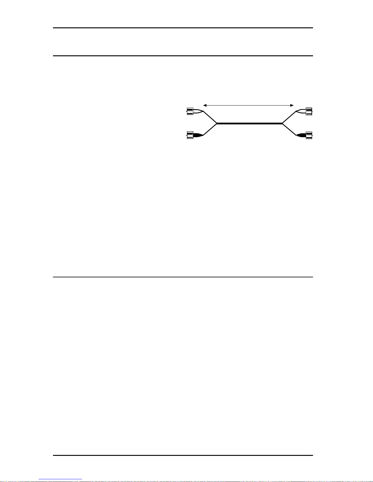
OMNIScanner User Guide
8 - 2
The Launch/Jumper Cable
The launch/jumper cables are 2 m fiber cables and need to be of good
quality and in excellent condition. Always clean and inspect the launch
cables before use.
Note: The launch cable used to set
the reference value should be the
same type of fiber as the cables to
be tested and certified, 50/125,
62.5/125 or single-mode.
The fiber cables included with your OMNI
Fiber
kit are duplex launch cables.
One fiber has white connector boots and the other fiber has black boots.
These colors are consistently used for all graphics throughout this user
guide to avoid confusion.
Fibers can be marked with other color schemes or cable markings to
differentiate them. Pay close attention to the colors to avoid improper fiber
connections.
The Reference Methods
For testing of networks with different connector styles, please consult the
Microtest web site (http://www .microtest.com/support/techbulletins/).
It is very important that the transmitter (TX port) connections are not disturbed after the reference value is established.
Note: When a connector is removed and then reattached, it is unlikely to go
back into the exact same position. As a result, measurements will change
when connections are made or broken.
OMNI
Fiber
measures two fibers of a duplex link in one Autotest operation.
Four reference values will be stored, two from OMNI
Scanner
to OMNI-
Remote
(TX - RX), the others from OMNI
Remote
to OMNI
Scanner
(TX -
RX).
2 m Launch Cable
Page 97
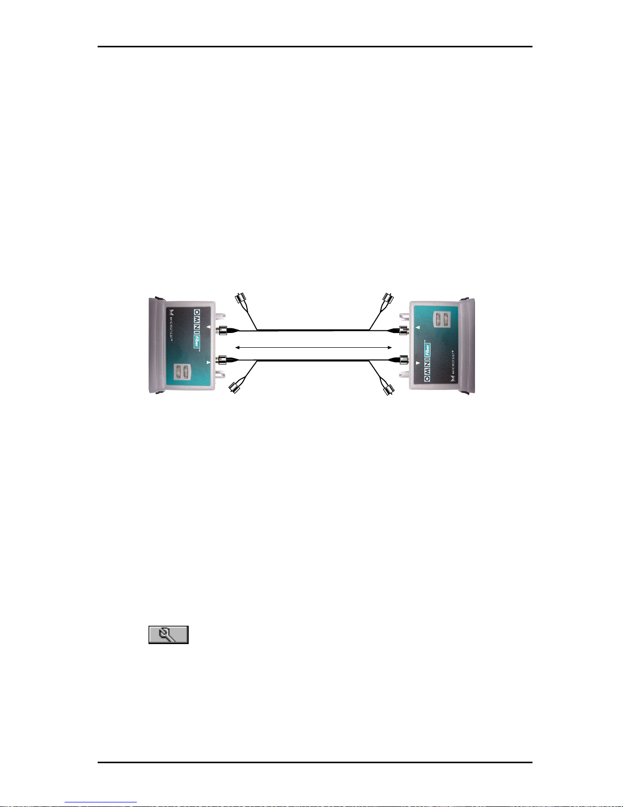
8 - 3
OMNIScanner User Guide
One Jumper Reference Method
This method is used when the link includes:
• the loss of one connection at the near end cross connect
• the loss of one connection at the far end cross connect/outlet
• the loss of the cable plant
TIA/EIA -568-A, ISO 1 1801, and IEEE 802.3 (100 Base-X, 1000Base-X)
specify the one jumper method.
Note: This method is called ‘Method B’ in TIA-526-14A and ’Method A.1’
in TIA-526-7.
1. Connect one end of a black launch cable to the TX (transmit) port of the
fiber adapter that is attached to OMNI
Scanner
.
2. Connect the other end of that black launch cable to the RX (receive) port
of the fiber adapter that is attached to OMNI
Remote
.
3. Leave the two white fiber connectors dangling and unconnected.
4. Connect one end of another black launch cable to the TX (transmit) port
of the fiber adapter that is attached to OMNI
Remote
.
5. Connect the other end of that black launch cable to the RX (receive) port
of the fiber adapter that is attached to OMNI
Scanner
.
6. Leave the two white fiber connectors dangling and unconnected.
7. Press (Setup) to open the SETUP screen and then select Set
Reference to set the reference.
8. Disconnect only the following two ends: OMNI
Fiber
Main RX (receive) and
OMNI
Fiber
Remote RX (receive). OMNI
Fiber
Main TX and OMNI
Fiber
remote TX stay connected!
9. Connect the white fibers to the appropriate RX ports.
RX
TX
850 nm
1300/1310 nm
RX
TX
850 nm
1300/1310 nm
2 m Launch Cables
Page 98
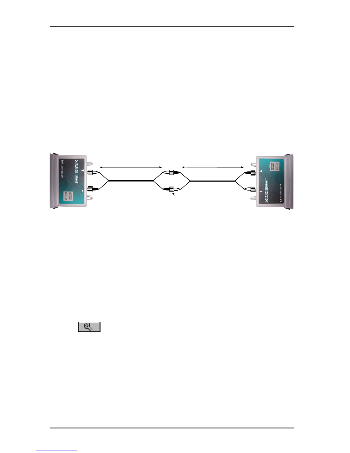
OMNIScanner User Guide
8 - 4
Two Jumper Reference Method
This method is used when the link includes:
• the loss of one connection at the near or far end cross connect
• the loss of the cable plant
TIA/EIA -455-171and IEEE 10 Base-X specify the two jumper method.
Note: This method is called ‘Method A ’ in TIA-526-14A and ‘Method A.2’
in TIA-526-7.
1. Connect a launch cable to the fiber adapter that is attached to OMNI-
Scanner.
The black fiber attaches to the TX (transmitter) port and the white
fiber to the RX (receiver) port.
2. Connect a launch cable to the fiber adapter that is attached to OMNI-
Remote.
The black fiber attaches to the TX (transmitter) port and the white
fiber to the RX (receiver) port.
3. Use a connector adapter to mate the two black fiber connectors.
4. Use a connector adapter to mate the two white fiber connectors.
5. Press (Setup) to open the SETUP screen and then select Set
Reference to set the reference.
6. Disconnect the connectors from the connector adapters without disturbing
the fiber connections to the OMNI
Fibers.
7. Set the connector adapters aside.
RX
TX
850 nm
1300/1310 nm
RX
TX
850 nm
1300/1310 nm
2 m Launch Cable
2 m Launch Cable
Coupler
Page 99
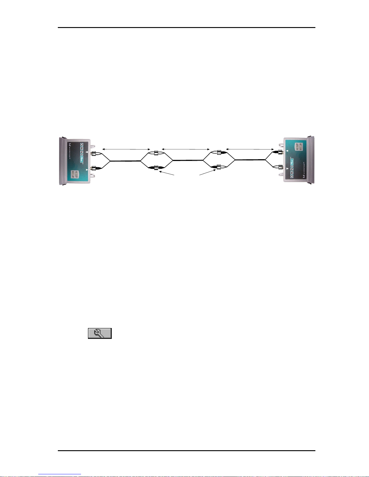
8 - 5
OMNIScanner User Guide
Three Jumper Reference Method
This method is used when the link includes:
• the loss of the cable plant
Note: This method is called ‘Method C’ in TIA-526-14A and ‘Method A.3’
in TIA-526-7.
1. Connect the first launch cable to the fiber adapter that is attached to
OMNI
Scanner
. The black fiber attaches to the TX (transmitter) port and the
white fiber to the RX (receiver) port.
2. Connect the second launch cable to the fiber adapter that is attached to
OMNI
Remote
. The black fiber attaches to the TX (transmitter) port and the
white fiber to the RX (receiver) port.
3. Use two connector adapters to mate the black TX connector to the
white RX connector through a third jumper cable.
4. Use two connector adapters to mate the other black TX connector to the
white RX connector through a third jumper cable.
5. Press (Setup) to open the SETUP screen and then select Set
Reference to set the reference.
6. Remove the third jumper cable, located in the center , and the connector
adapters without disturbing the OMNI
Fiber
connections.
RX
TX
850 nm
1300/1310 nm
RX
TX
850 nm
1300/1310 nm
2 m Launch Cable
Couplers
2 m Launch Cable 2 m Launch Cable
Page 100
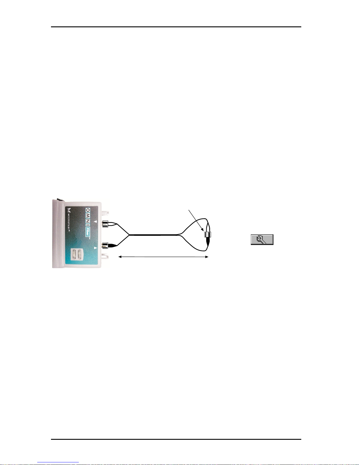
OMNIScanner User Guide
8 - 6
RX
TX
850 nm
1300/1310 nm
2 m Launch Cable
Coupler
Two Jumper Reference Method in Loopback Mode
The OMNI
Fiber
Main can be used without the remote to make measurements on a single fiber. In this state the TX fiber is looped back to the RX
port of the same OMNI
Fiber
adapter .
Note: During the Autotest, the loss and length of the white fiber will be
subtracted from the length of the fiber under test. Since the loss in a short
jumper cable is negligible, the loss measurement of the fiber under test will
be accurate. The length measurement will be off by the length of the jumper
cable (about 2 meters). This primarily affects the length accuracy of very
short cables.
1. Connect the launch cable to the OMNI
Fiber.
The black fiber attached to
the TX (transmit) port and the white fiber to the RX (receive) port.
2. Use a connector
adapter to mate the
connections on the
other end.
3. Press (Setup)
to open the SETUP
screen and then select
Set Reference to set
the reference.
4. Disconnect the white connector from both the RX port and the connector
adapter . Do not disturb the black fiber attached to OMNI
Fiber’s
TX port.
5. Leave the two white ends dangling.
6. Attach the cable to be tested to the connector adapter and the
OMNI
Fiber’s
open RX port .
 Loading...