

Page 1

HI-POT Tester
7630
User’s Manual
Version: 1.2
Issued Date: March 2017
Page 2

Copyright and Trademark
Do not attempt to reproduce any part of this publication or transmit it by any form or
method, whether through electronic, mechanical, copying, recording or other means,
without the prior written permission of Microtest Co., Ltd. We shall neither be
subjected to any responsibilities or obligations for the information contained in this
Manual nor bear damage responsibility resulting from the use of the information
contained herein. All brands and trademark are the properties of Microtest Co., Ltd.
Microtest Co., Ltd. and its affiliates shall not be liable for the damage, losses or costs
incurred due to the accidental use, misuse or abuse by the product buyer or the third
party; or the unauthorized modification, repairs or change of the product; or the failure
in following the operation and maintenance instructions established by Microtest.
The content and the product specifications shall be subject to change without further
notice.
2015 @ Microtest Corporation. All rights reserved.
Page 3

Table of Contents
1.
Safety Instruction .......................................................................... 1
1.1 Electrocution ............................................................................................... 1
1.2 Grounding .................................................................................................... 1
1.3 Power Source ............................................................................................... 1
1.4 Connecting the Tester Table to the High Voltage Output Terminal ............. 2
1.5 Warm-up ...................................................................................................... 2
1.6 External control unit .................................................................................... 2
1.7 Machine failure ............................................................................................ 2
1.8 Ending the test ............................................................................................. 2
1.9 Installation, storage ..................................................................................... 3
1.10 Emergency treatment ................................................................................... 3
2 General Summary ......................................................................... 4
2.1 Package and Accessories ............................................................................. 4
2.2 Front Panel ................................................................................................... 5
2.3 Rear Panel .................................................................................................... 6
3 Basic operation ............................................................................. 7
3.1 Function block diagram ................................................................................ 7
3.2 Standby screen ............................................................................................. 8
3.3 System settings (SYSTEM) .......................................................................... 10
3.4 Function (FUNC) ......................................................................................... 12
3.5 Specification setup 1 (SETUP) .................................................................... 14
3.6 Specification setup 2 (SETUP) .................................................................... 16
3.7 File management (FILE) .............................................................................. 18
4 Start testing ................................................................................ 21
4.1 Before testing ............................................................................................. 21
4.2 Testing in progress...................................................................................... 22
4.3 Ending a Test .............................................................................................. 23
4.4 Release determination results ................................................................... 24
5 Remote control I/O (REMOTE) .................................................... 25
6 RS-232/USB device ...................................................................... 28
6.1 RS- 232 interface ........................................................................................ 28
6.2 Command format ....................................................................................... 28
6.3 Connector ................................................................................................... 28
Page 4

6.4 Connection cable and method ................................................................... 29
6.5 USB device interface .................................................................................. 30
7 Remote Command ...................................................................... 31
7.1 Instruction summary .................................................................................. 31
7.2 Command description ................................................................................ 33
Appendix 1 Error message .............................................................. 41
Page 5

1
1. Safety Instruction
This instrument is designed according to EN61010-1 Specification. The main
purpose of this Specification is to ensure that the instrument will be used in the
laboratory or the factory safely; it is not suitable for outdoor applications,
especially the moistened or dusty locations. Abnormal use of this instrument may
cause the electrocution hazard. Before using this instrument, please read the
descriptions of this Specification carefully to avoid causing accident due to
incorrect or unintended use.
1.1 Electrocution
To prevent electrocution accident from occurring, it is suggested that the
operator wear insulating rubber globes before working with the machine and
then start the test-related activities.
1.2 Grounding
The back panel of the instrument is fitted with a safe ground terminal. Be sure to
connect this ground terminal to the ground to prevent the operator from
touching the housing as to cause the electrocution.
1.3 Power Source
Power that can be used with this tester is AC 100Vac~240Vac with a frequency
range between 47Hz~63Hz; please confirm whether the input power voltage and
frequency are within range before plugging in the power.
Page 6

2
1.4 Connecting the Tester Table to the High Voltage Output Terminal
While the tester is off, connect the high voltage tester cables to the high voltage
output terminal of the tester and make sure that there are no ruptures outside
the cables and that the cables are not loose.
1.5 Warm-up
The instrument will operate normally upon starting the power. To achieve the
specified accuracy, it is suggested warming up the instrument for over 15
minutes.
1.6 External control unit
This unit is able to execute the external control. For this purpose, please ensure
that the operator is not touching the signal output end and the Test Piece to
avoid causing hazard.
1.7 Machine failure
Stop using the instrument immediately when finding it is operating abnormally,
such as significant difference is existed between the current displayed on the
current meter and the design value; or the current is not supplied, but the
overlapping current indicator remains illuminated continuously. In this case,
please contact us or your dealer to provide technical support.
1.8 Ending the test
When not using the instrument, please shut off the Power Switch. To restart the
Power Switch after being disconnected, please wait for few seconds; however,
Page 7

3
do not execute consecutive on/off action of the power.
1.9 Installation, storage
Normal operating temperature and humidity scope of the instrument is
5oC~40oC and 80% RH respectively, and the instrument may act abnormally if
exceeding such range. The storage temperature and humidity scope of the
instrument is -20oC~ 70oC and 80% RH respectively. To achieve correct testing
and to protect safety, do not install the instrument in the environment exposing
to direct sunshine or high temperature, high humidity, frequency oscillation and
rich dust.
1.10 Emergency treatment
Upon the occurrence of electrocution, burning of the Test Piece or the burning
of Main Unit, please disconnect the Power Switch and remove the power cord
plug immediately to avoid causing a hazard.
Page 8
4
2 General Summary
In this chapter, we briefly introduce the characters, key features and
specifications of 7630 Precision Hi-Pot Tester.
2.1 Package and Accessories
Standard accessories included in the 7630 hipot tester package should include
the following items:
• HT- 7630
X 1
• HV cables (red)
X 1
• Low voltage cables (black)
X 1
• Power Cord
X 1
• HT- 7630 User’s Manual CD
X 1
• Inter lock cable
X 1
Page 9
5
2.2 Front Panel
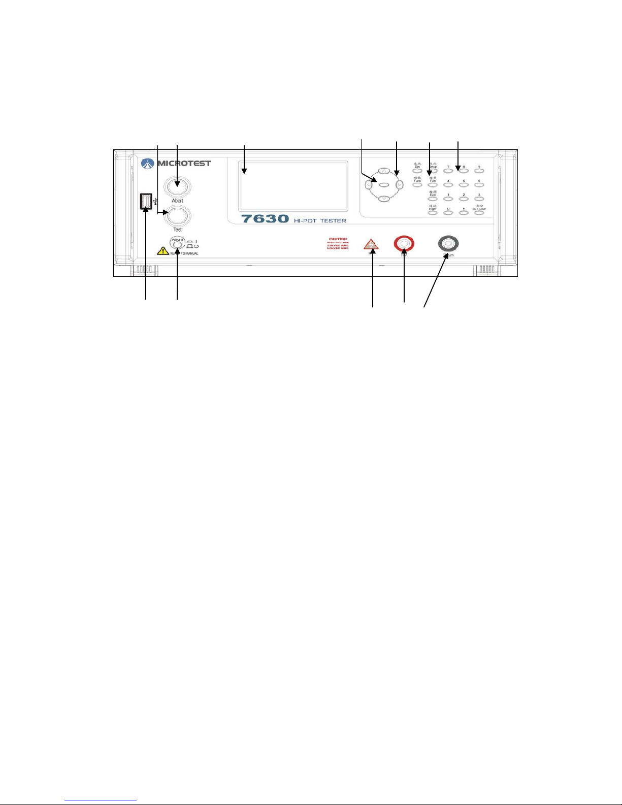
(1) Test key (with PASS light indicator): Press to start testing the system in READY
mode, it lights up after being tested successfully.
(2) Stop key (with FAIL light indicator): Press to stop the test and close the high
voltage output in test mode. It lights up when the test has failed. Press it to mute
the alert buzzer.
(3) LCD color display: Display settings and test results
(4) Software key: These five software keys have functions as indicated by their
screen, e.g. copy or delete. In case no functions are signed to a key, it displays a
blank screen.
(5) Arrow key: These keys move the cursor for editing. The center key functions the
same as the OK function key.
(6) Function key: Press to set up a function represented by the key which will be
detailed later.
(7) Numeric key: Press to edit numeric data.
(8) USB port: Connect USB storage for setup file access and firmware updates.
Note: It supports FAT format only.
(9) Power switch: Power on or off the host.
(10) High voltage output light indicator: It lights up when there is a current output.
DO NOT touch the high voltage output port when this light is on as you may get
shocked.
(11) High, low voltage output port: Port for output test.
(1) (2)
(3)
(4) (5) (6) (7)
(8) (9)
(10) (11)
Page 10
6
2.3Rear Panel
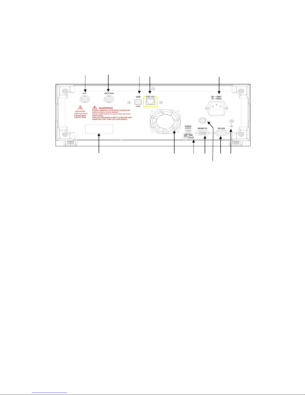
(1) High voltage output terminal: Connection to the expansion box
(2) Low voltage output terminal: Connection to the expansion box
(3) USB port: Connection to the computer for controlling the machine with
computer instructions
(4) Expansion box port: Connect this port and an expansion box with a connection
cable
(5) AC power socket: AC power input connector with a 250V/3.15A fuse
(6) Iron casing terminal: Ground your machine with this terminal for more steady
device operation
(7) RS-232 connector: Connect to the computer to control your machine with
computer instructions
(8) High voltage tester port: Connect the high voltage tester to this port
(9) Remote controller port: Signal for external control including the determination
and testing signal output or input of an external signal for test start and stop
(10) Inter Lock port: High voltage current output safety switch. Short circuit both
ends of this port during testing for the test voltage output. Opening the circuit of
this port during testing will stop the test and prompt the message “INTER LOCK”
(11) Exhaust outlet: Air exhaust for cooling
(12) Serial number sticker: Indicates the serial number of your machine
(1) (2)
(3) (4)
(5)
(6)
(7)
(9)
(10
(11) (12)
(8)
Page 11
7
3 Basic operation
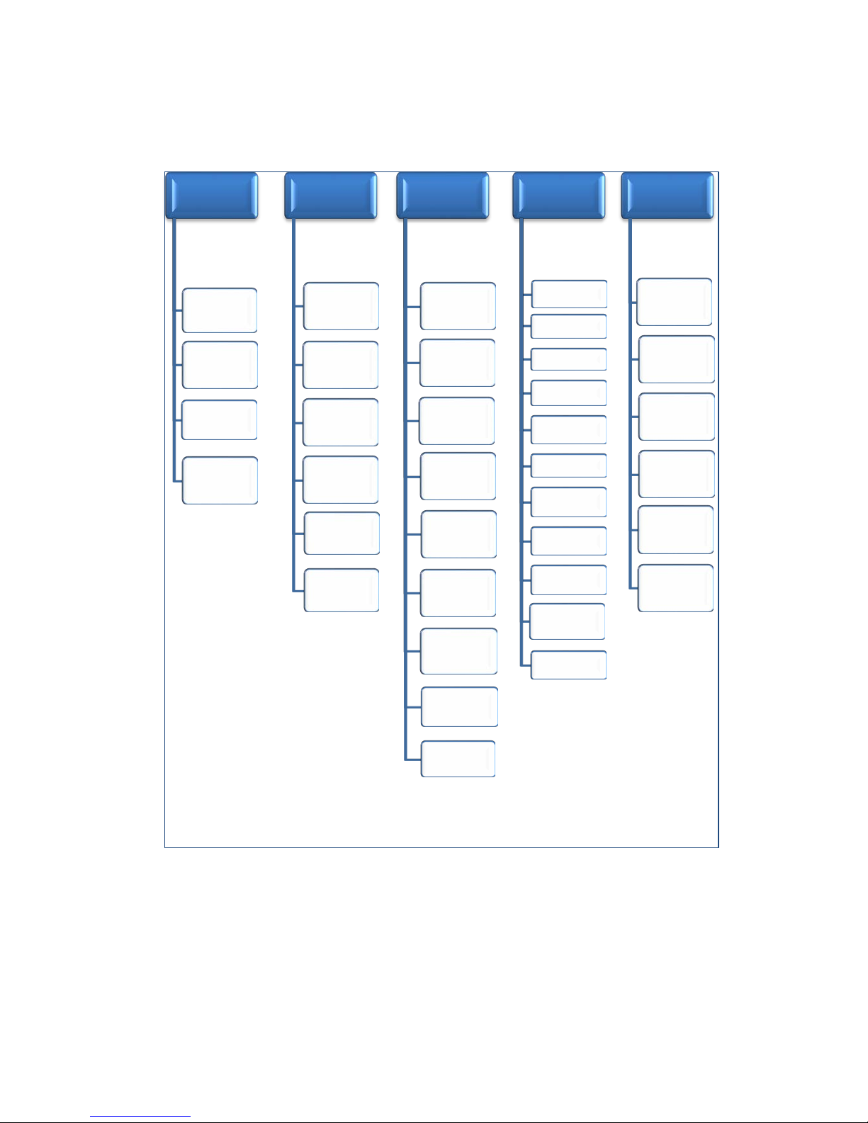
3.1 Function block diagram
Ready
Sys
Setup
Config
File
Sys
Baud Rate
Upload
Data
Key Sound
PassWord
Pass
Volume
Fail Volume
Setup
MODE
VOLT
FREQ
HI.
LO.
Ramp
DWEL
ARC
OFFS
OPEN
DLAY
Func
Key Lock
Pass Hold
Time
Trig Wait
Time
Alarm
Mode
Instant
Test Mode
Next Step
By
Break Test
Output
Signal
File
Save As..
Load File
Del. File
New File
Save File
To USB
Save File
From USB
Page 12
8
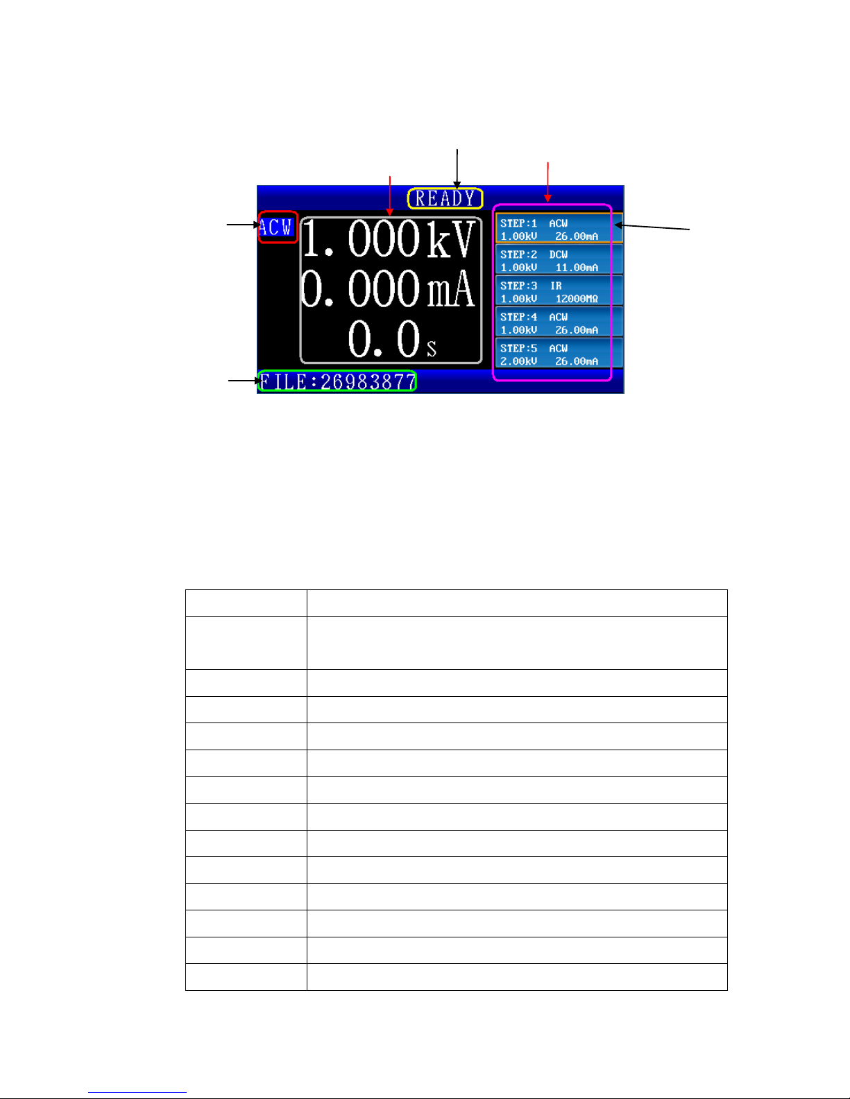
3.2 Standby screen
(1) Display the current test mode: Message “ACW” for AC voltage testing, “DCW”
for DC voltage testing, “IR” for insulation impedance testing
(2) Readings of the voltage, current (resistance in IR mode), and test time of the
measurement output port now. It displays the current voltage and test time
settings if no test is running now.
(3) Display the current status of your machine as illustrated in the table below:
Status display Description
READY Your machine is ready for testing now, press the TEST key to
begin testing
TEST Testing now
WAIT The Trig Wait Time which can be set up in the CONFIG menu
WAIT KEY Waiting for the trigger signal for the next test
PASS Tested successfully (qualified goods)
Break Down Leak current exceeds the maximum measurement
Arcing Arc exceeds the upper limit
Lo-Limit Measurement exceeds the lower limit
Hi-limit Measurement exceeds the upper limit
FAIL At least one step in a multi-step test failed
INTER-LOCK High voltage safety lock on
VOLT-ERROR Voltage output error
OPEN Test wire disconnection error
(6)
(5)
(1)
(2)
(3)
(4)
Page 13

9
(4) Display the first five test steps of the current file
(5) The orange color framed step is the one under testing (DUT) now along with its
specifications displayed. You may select the desired step by moving the cursor
to it with arrow key. Press the ENTER key to set up the test items.
(6) Display the name of the current file. The name appended with an asterisk “*”
suggests the file has been edited but not saved. In this case the current
settings cannot be copied to a mobile storage device.
Page 14
10
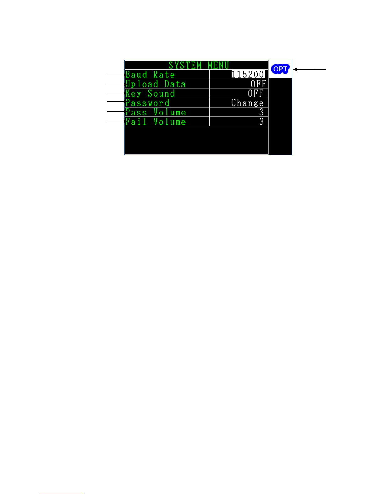
3.3 System settings (SYSTEM)
(1) Baud Rate: You may set up a transmission speed of RS-232 to 9600, 19200, 38400,
57600, or 115200. Please note that this needs to be aligned with the speed at the
control end.
(2) Upload Data: Automatically uploads the test results.Available options include OFF,
RS-232, FLASH and BOTH. When the function is set as RS-232, the machine will
automatically respond the current status. The statuses include: The machine will
return the POWER ON and START strings when the machine is turning on, and the
machine will return the current test step and result when the test ends. For
example 01,ACW,1.001e+03,7.169e-06,PASS; in which the data has a total of five
fields that are separated by commas. The first field represents the test step
number; the second field represents the test mode, which includes the seven
types ACW, DCW, IR, CO N TAC T, ACW-P, DCW-P and IR-P. The third field represents
the output voltage during the test, which is marked with a scientific symbol. The
fourth field represents the electric current value during the test, which is marked
with a scientific symbol (this field returns the resistance value if the test item is
IR). The fifth field represents the test result, which includes PASS (good product),
HI-Limit(exceeded the maximum limit set), Lo-LIMIT(lower than the minimum
limit set), INTER-LOCK(high voltage safety lock enabled), ABORT(test interrupted),
BREAKDOWN(breakdown point detected), ARCING(discharge detected), VOLT
ERR(voltage output error), and OPEN(DUT connection error). If multi-step test is
performed, the final judgement result will be added when the test is completed.
When the function is set toFLASH, once the machine test has ended, it will
automatically write the test result into the mobile storage device.Its format is the
(1)
(2)
(3)
(6)
(5)
(4)
(7)
Page 15

11
same as the RS-232 contents. The data storage path is \7630\STAT\current test
file name.csv. When the function is set as BOTH, both the actions described
above will be performed. When the function is set as OFF, this function is
disabled.
Note: When the RS-232 and FLASH functions are enabled, since it takes some
time to transmit the data (differs according to the transmission rate set and
mobile access device), therefore there will be some time delay for continuous
or multi-step tests.
(3) Key Sound: Switch the key sound on/off (the keyboard clicks after a key is pressed
successfully).
(4) Password: This is the password protecting the keyboard lock. When the latter is
on you have to input the correct password to unlock the keyboard. You may
change the password here. Its factory default value is 7630.
(5) Pass Volume: Volume for qualified goods after testing. You can set the volume in
5 steps from 1 to 5 with 1 being the softest and 5 the loudest. You can mute the
pass sound in the FUN mode.
(6) Fail Volume: Volume for failed goods after testing. You can set the volume in 5
steps from 1 to 5 with 1 being the softest and 5 the loudest. You can mute the fail
sound in the FUN mode.
(7) OPT: When this symbol appears on the screen, press the software keys to adjust
the option.
Page 16
12
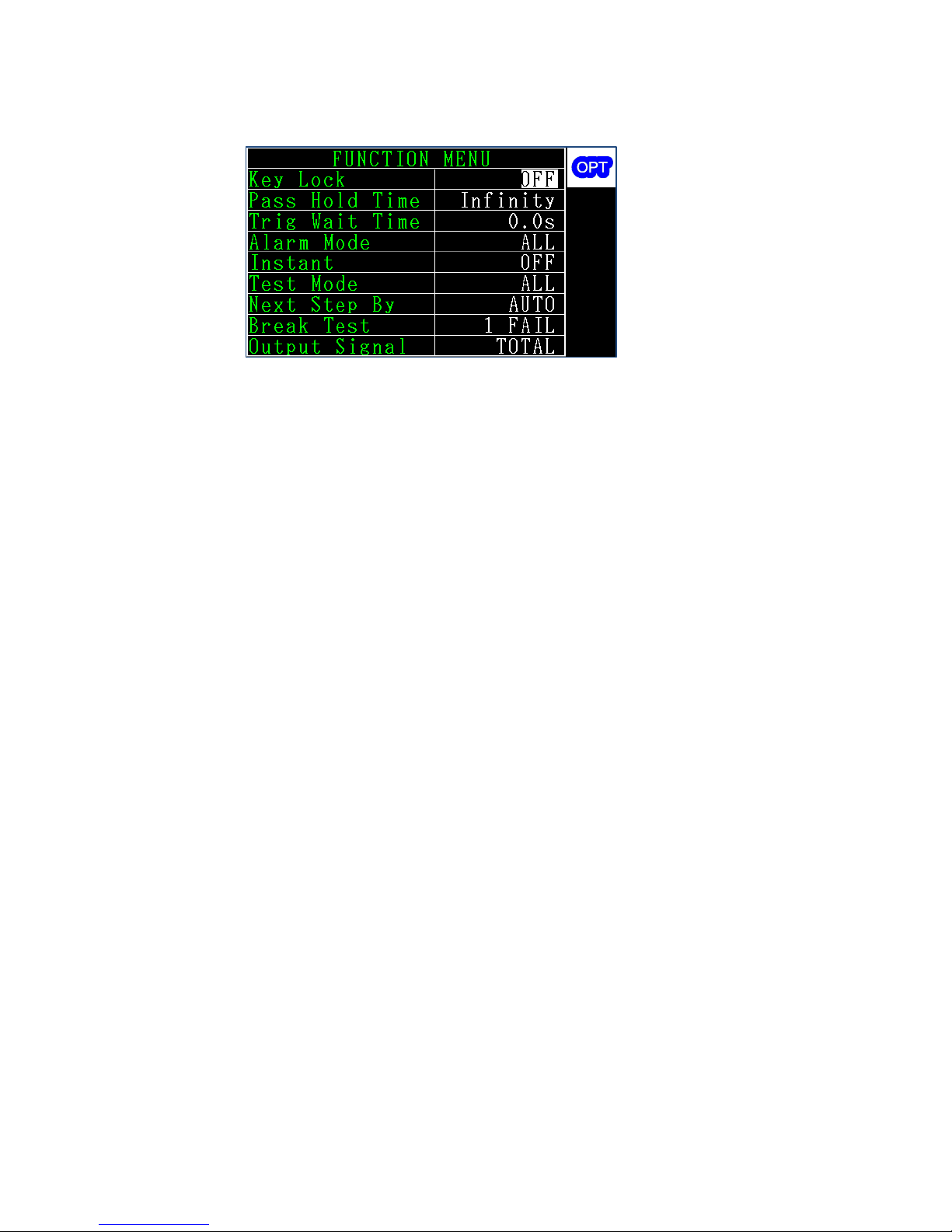
3.4 Function (FUNC)
(1) Key Lock: Keyboard lock prevents the test conditions from changes by unexpected
user operation. Once it is on, users can start and stop the test without changing
any settings. To unlock the keyboard, input the password you set earlier. To
change the password, please refer to the system setup steps given earlier.
(2) Pass Hold Time: The Retaining time for the qualified goods message display. Your
machine prompts the message “PASS” and the output signal at the remote control
port once a product is tested as qualified. This function sets up a time span of
message display and signal output with the options of 50mS, 100mS, 500mS, 1S,
2S, 5S and Infinity. The “Infinity” option keeps on displaying test results until the
ABORT key is pressed.
(3) Trig Wait Time: This is the time span after your machine enters the test page (the
“WAIT ” message prompts in the status column) by pressing the test key until there
is a high voltage current output for the test. This is used to get the test jig
triggered and positioned for testing.
(4) Alarm Mode: The alert mode has the options of ALL (alert all), PASS (alert for
qualified goods), FAIL (alert for failed goods), and OFF.
(5) Instant: You have to press and hold the TEST key to run the test in this mode.
Release the key and the test stops immediately.
(6) Test Mode: You may run the test in a single- or multi-step mode. You may press
the up and down arrow key in single-step mode to select the desired test step and
get test results immediately. Your machine begins test with the first step in SETUP
through to the last one in multi-step mode. Test results are determined by the
subsequent settings.
(7) Next Step By: In multi-step mode your machine runs the next step based on the
Page 17

13
given trigger source after the first one has ended. With the option “AUTO”, the
test runs the next step automatically; “Trig”, the next step, will run only after the
TEST key is pressed. This item is available only when Test Mode is set to the
option ALL.
(8) Break Test: In multi-step mode, your machine stops or continues the test based
on the settings in this field in case the results are failed goods. With option “1
FAIL”, the test stops immediately in case of failed goods; for “OFF”, the test ends
only after the last step is executed. This item is available only when Test Mode is
set to the option ALL.
(9) Output Signal: In multi-step mode, your machine gives a results signal in case this
is set to the option “EACH”; with the option “TOTA L” it gives the output signal
“PASS” or “FAIL” only after the test has ended.
Page 18
14
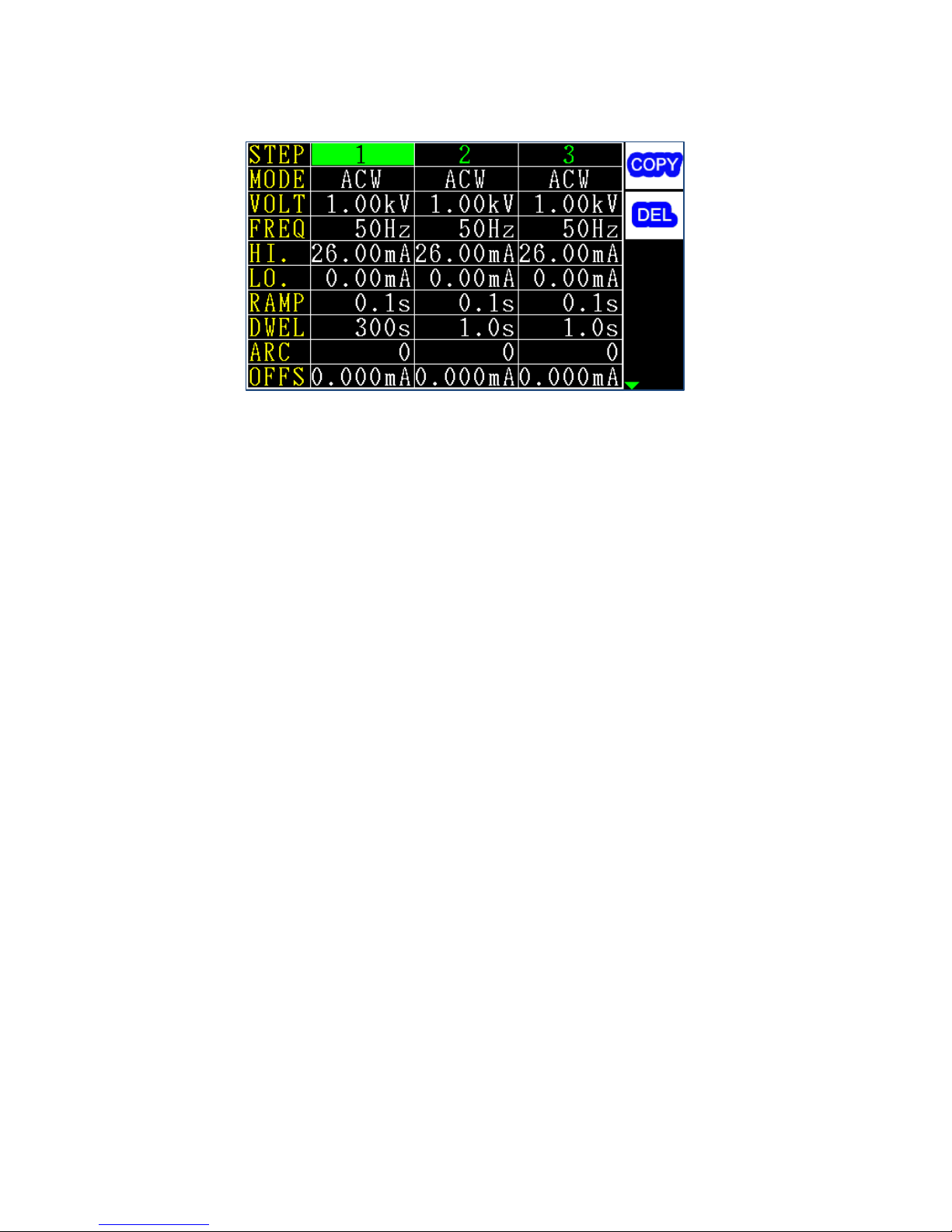
3.5 Specification setup 1 (SETUP)
(1) STEP: Step ID. Each file can have up to 16 steps. Press the software key COPY to
add the next step; press the software key DEL to delete the step where the cursor
is positioned. Each file must have at least one step.
(2) MODE: There are three test mode options: ACW, DCW, IR which you can select
with a software key.
(3) VO LT: Set up the test voltage by typing its value with a numeric key. The
maximum voltage varies with the test mode for ACW: 5.0kV, DCW: 6kV, IR: 1kV.
Their minimum values are all 0.1kV.
(4) FREQ: You may opt for a test frequency of 50Hz or 60Hz.
(5) HI.: This is the upper limit of measurement. In case test readings exceed this limit
the test has failed and is ended immediately. This value varies with the test mode
for ACW: 26mA, DCW: 11mA, IR: 1200MΩ. For IR tests with settings at 1200M, no
upper limit will be judged.
(6) LO.: This is the lower limit of measurement. In case test readings exceed this limit,
the test has failed and is ended immediately. For settings at a value 0, no lower
limit will be judged.
(7) Ramp: This is the time span for the voltage to rise from 0 to the target value
ranging from 10S to 0.1S.
(8) DWEL: This is the time span for sustaining the test after the voltage reaches the
given settings. For a setting of value 0, the test continues until the stop key is
pressed or the test fails.
(9) ARC: This item sets up arc sensitivity. The greater the value is, the less sensitive
the arc detection is. Setting it to 0 will disable your machine from making any
Page 19

15
judgment over the arc during the test.
(10) OFFS: This item resets the test end to prevent the impact of the external jig on
accuracy. It deducts the leak current by the jig in advance and displays the actual
leak current of the DUT with the equation “measurement readings = actual
measurement less reset value”. This item has two options: Manual and auto. The
first requires manual input of the leak current value. The second contains the
following steps: Remove the DUT from your machine; point the cursor to the field
OFFS and press the software key AUTO; your machine measures according to the
given voltage statistics and prompts the results; the message “SAVE=ENTER”
displays after the measurement operation is done; press the ENTER key to save
the test value or the EXIT key to exit without saving it; the saved value will be
deducted from each measurement to enable a more accurate test.
Page 20
16
3.6 Specification setup2 (SETUP)
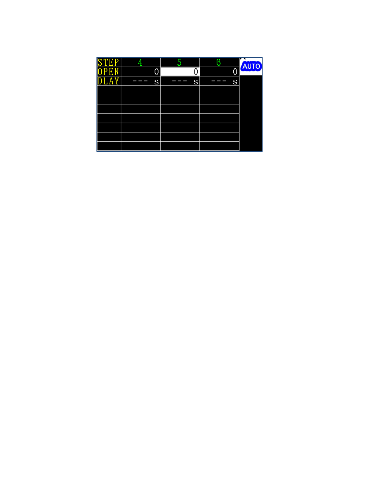
(1) OPEN: Open circuit detection sensitivity. Poor connection of the high voltage test
wire to the DUT may lead to a lower measurement current and invalid qualified
product results in the voltage test. Once this function is enabled (with non-zero
settings) your machine will measure the DUT's capacitance with low voltage for
about 200ms before the high voltage test begins. In case the measured
capacitance value is lower than the settings, the test wire may not be connected
to the DUT properly and your machine will stop the test and prompt the message
“OPEN”.
You may set this in two options: Manual and auto. The first requires manual input
of the given value. The second contains the following steps: Connect the DUT
properly; point the cursor to the field OPEN and press the software key AUTO;
your machine measures the given output channel and prompts the results; the
message “SAVE=ENTER” displays after the measurement operation is done; press
the ENTER key to save the test value or the EXIT key to exit without saving it.
Note: In case readings with or without connection to the DUT differ from each
other in a range less than 20, then its capacitance is too small and may not be
valid for using this method for an open circuit test.
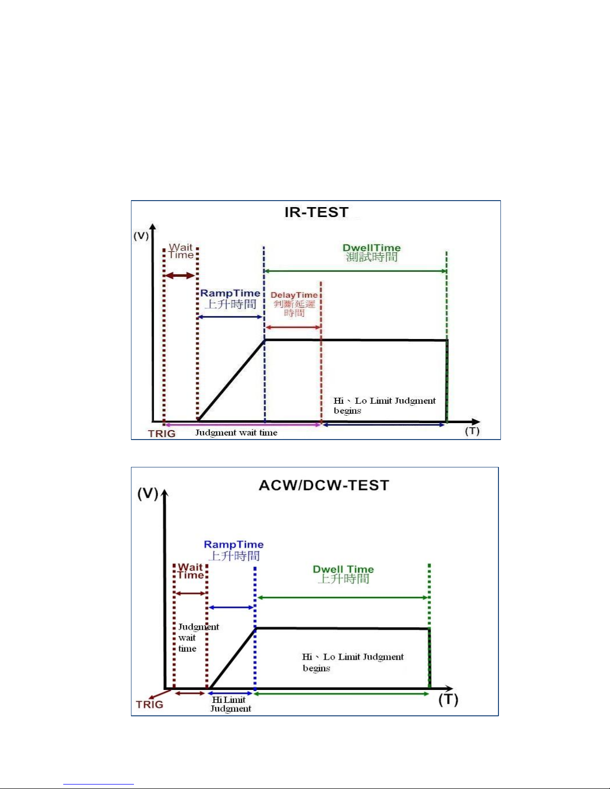
(2) D LAY: This item is aimed at judging the delay time and is editable only in IR
mode. For IR tests of the DUT with capacitance, this can be judged only after the
capacitor is fully charged. The delay time starts counting only after voltage has
reached the settings. Before that, your machine displays measurement without
the upper and lower limit determination and enters judgment mode immediately
after the delay time has expired. As the delay time is contained in the test time,
Page 21
17
its settings must be lower than the latter.
(3) High voltage output time and results determination timing: See the diagrams
below for the results determination the timing after the TEST key is pressed by
the user. Please note that in the IR delay and ascending time, no upper and lower
limit will be determined while only the upper limit will be determined in the
ascending time of the ACW and DCW modes.
Page 22
18
3.7 File management (FILE)
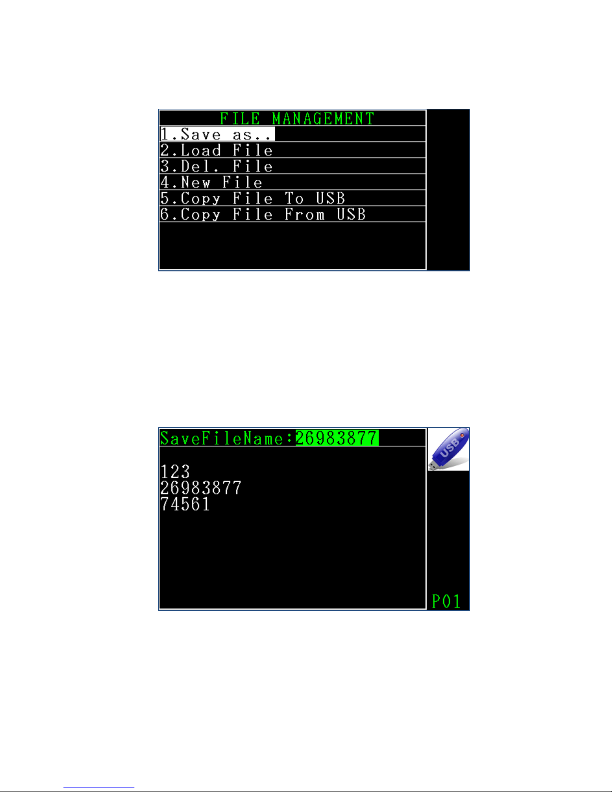
(1) Save As..: This option saves the setup file with a new file name (there can be up
to 30 files saved in your machine). The “file save” page displays the existing files
in your machine. In case a USB drive is connected, a USB icon shows in the upper
right corner of the page. You may press the software key to select saving a file in
the USB drive or internal memory. You can type a new file name or select an
existing file with the arrow key as shown in the figure below.
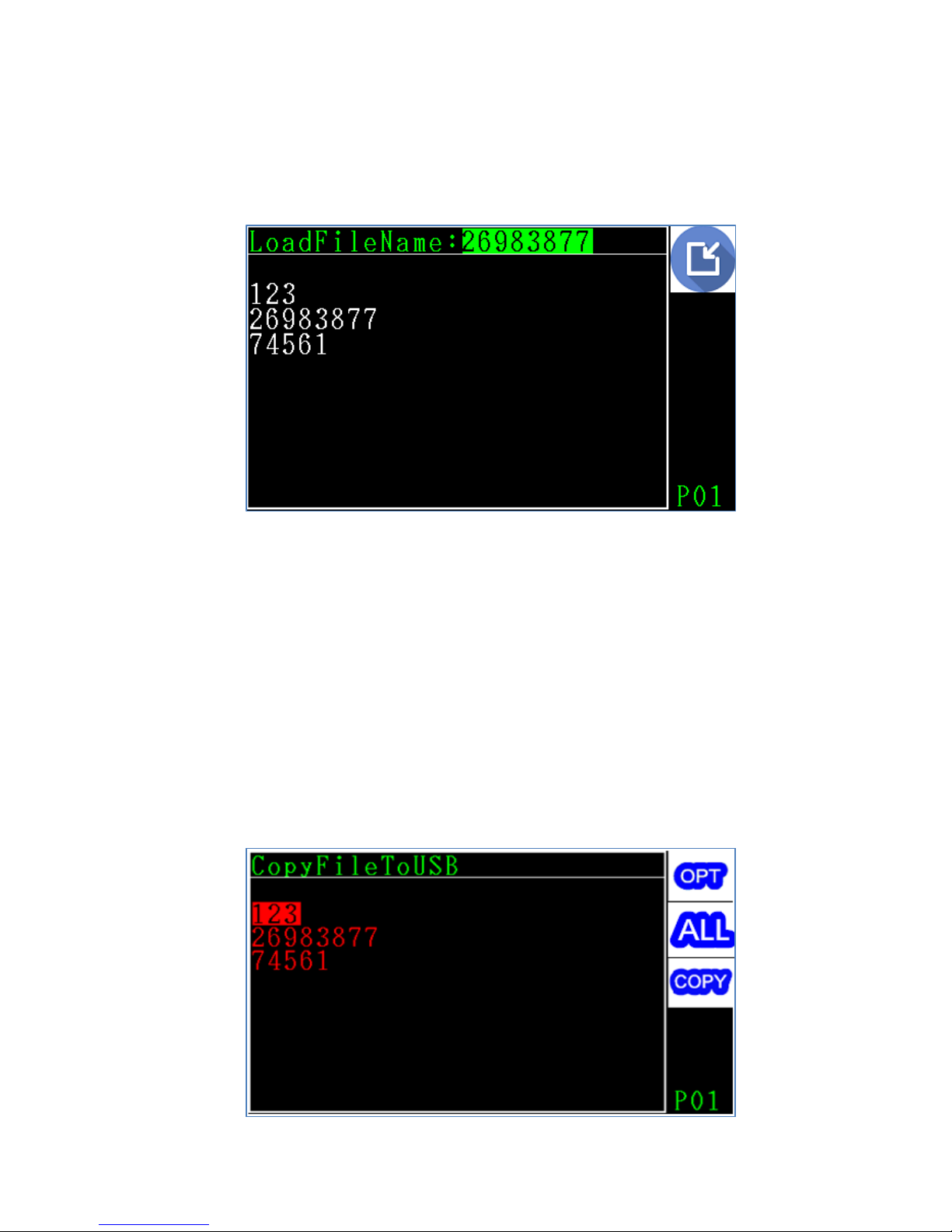
(2) Load File: This item reads the existing file. The “file access” page displays the
existing files in your machine. In case a USB drive is connected, a USB icon shows
in the upper right corner of the page. You may press the software key to select
retrieving a file in the USB drive or internal memory. You can type the file name or
Page 23
19
select the existing file with the arrow key as shown in the diagram below. Please
note that all setting files are auto generated by your machine. DO NOT edit this
data as the file may be damaged or the machine may run improperly.
(3) Del File: This item deletes the file in a manner similar to saving or retrieving it.
(4) New File: This item initializes all existing files and creates a new one.
(5) Copy File to USB: This item copies the existing setup files to a USB drive and
overwrites any one in the latter with the same name. Enter this page to display
the files existing in your machine, press the software key OPT to select one or
more desired files, press the software key COPY to start copying the selected files.
You may press the software key ALL to select all files shown in the current page
for copying. Please note that the ALL option is valid for files on the current page
only. For files on the next page, do the same to copy them as shown in the
diagram below.
Page 24
20
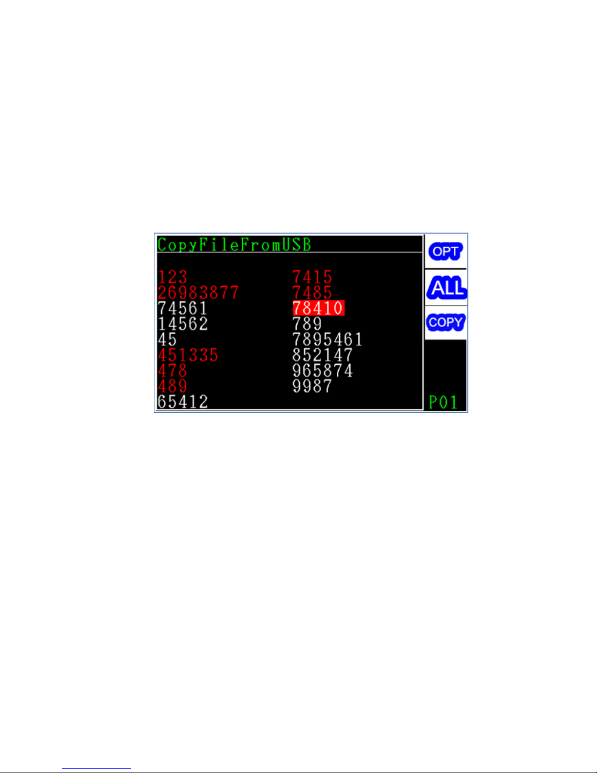
(6) Copy File from USB: This item copies the existing setup files to your machine from
the USB drive and overwrites any one in the former with the same name. Enter
this page to display the files existing in USB drive, press the software key OPT to
select one or more desired files, press the software key COPY to start copying
selected files. You may press the software key ALL to select all files shown in the
current page for copying. Please note that the ALL option is valid for files on the
current page only. For files on next page, do the same to copy them as shown in
the diagram below.
Page 25
21
4 Start testing
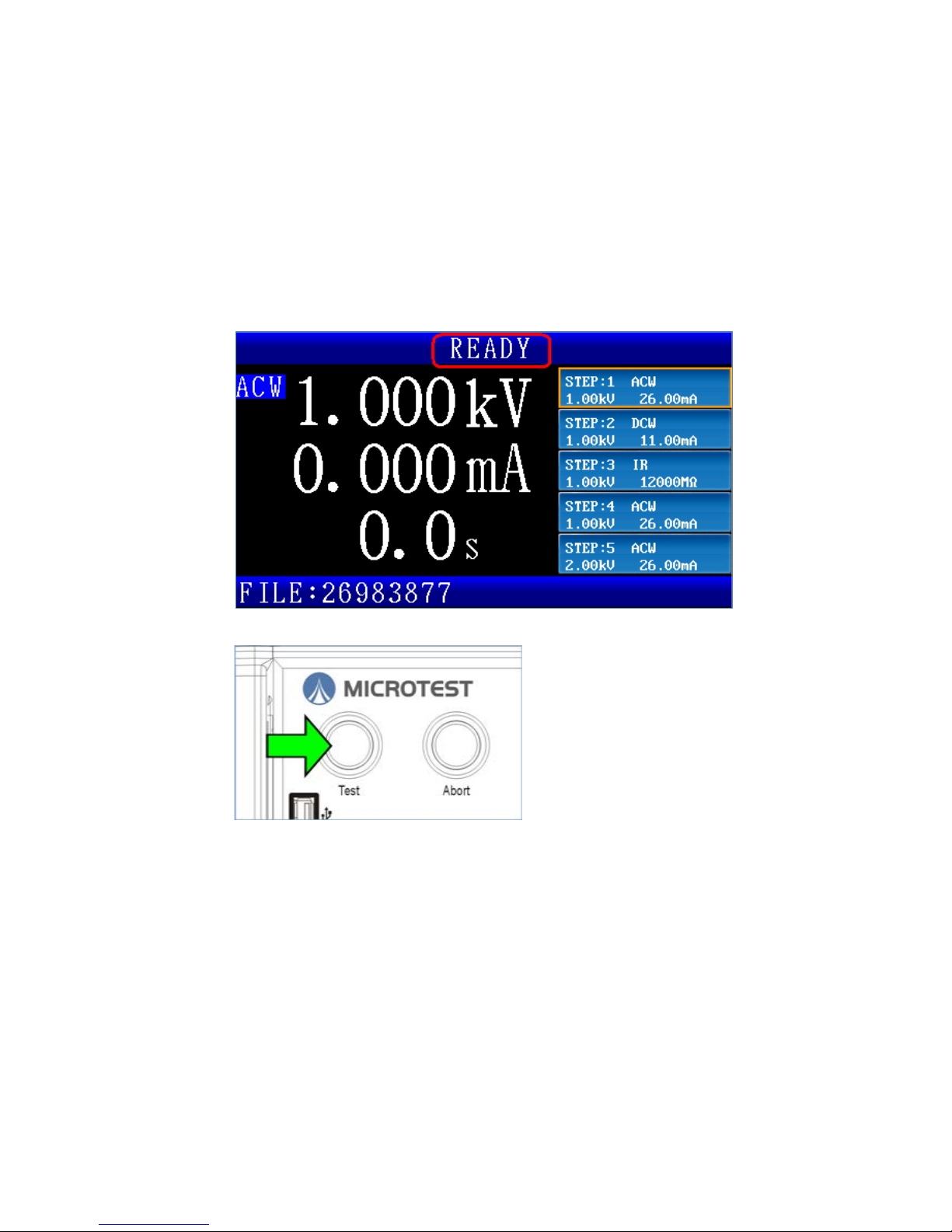
4.1 Before testing
(1) Validate specification setup
(2) Validate the proper connection between your machine and DUT
(3) Validate that the message READY is prompted
(4) Press the TEST key to start testing
Page 26
22
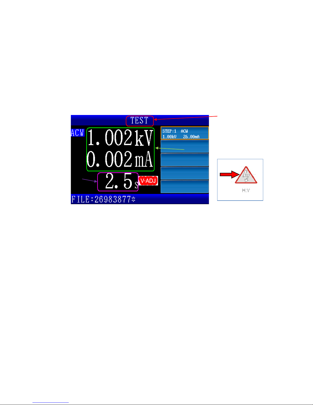
4.2 Testing in progress
(1) The message TEST is shown in the message column
(2) The high voltage output light indicator is ON in the front panel
(3) Measure the output voltage and leak current
(4) Test time counting. For tests lasting longer than 100 seconds, their integral
portion is displayed while the decimal portion is hidden; if it is longer than 999
seconds then it stops counting the time while the number 999 remains flashing
on screen.
(1)
(2)
(3)
(4)
Page 27
23
4.3 Ending a Test
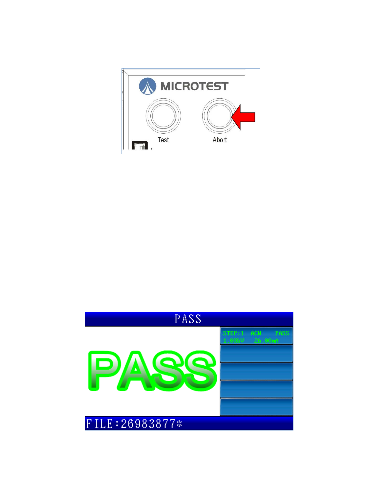
(1) Press the ABORT key to stop testing.
(2) Current/resistance measurements over the upper limit (HI-LIMIT)
(3) Current/resistance measurements below the lower limit (LO-LIMIT)
(4) Leak current over the maximum measurement (Break Down)
(5) Arc is over the settings (Arcing)
(6) Output safety switch is enabled (Inter Lock)
(7) Test DUT open circuit
(8) Test time expired
The test ends in case of any of the above. The high voltage output light indicator
turns off and the high voltage output closes after the test has ended. Tests
ended because of the conditions 2-8 described earlier will prompt
determination results.
Page 28
24
4.4 Release determination results
(1) After the test time has expired, the PASS light(green) indicator turns on and the
screen shows“PASS”. After the PASS HOLD time has expired, the page refreshes
to READY status and the PASS light indicator turns off. In case PASS HOLD is set
to Infinity, then you have to press the ABORT key to release the determination
results display.
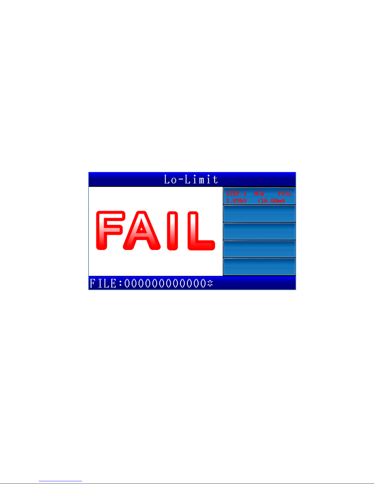
(2) In case the test fails then a red FAIL light(red) indicator turns on and the screen
shows“FA I L”. You have to press the ABORT key to release the determination
results display.
Page 29
25
5 Remote control I/O (REMOTE)
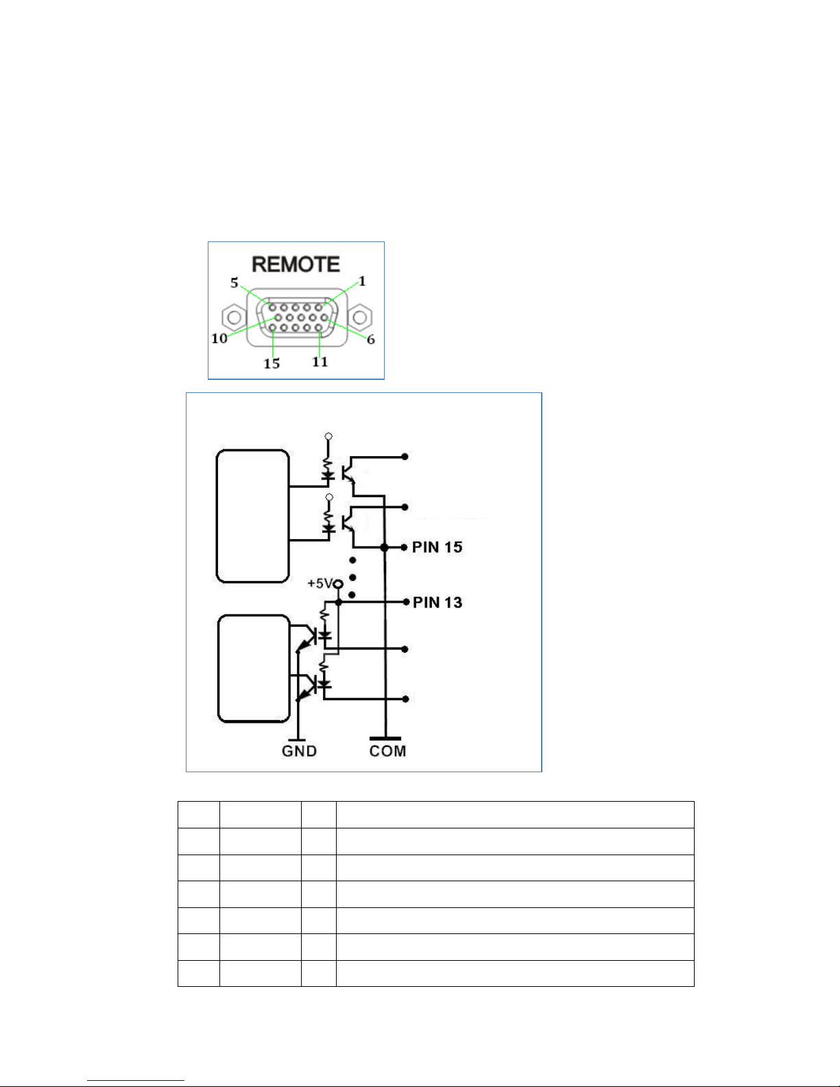
The rear panel of your machine comes with a remote control connector
(REMOTE). Please connect the control wire to it to enable controlling your
machine with an external signal. In cases like this, the test operator will not
touch the high voltage output end to prevent personal injury.
Pin Name I/0 Function
1 CTL1 O Reserved
2 CTL2 O Reserved
3 CTL3 O Reserved
4 CTL4 O Reserved
5 TESTING O Test in progress
6 PASS O Determination PASS
Internal wiring
Output
signal
controller
Input
signal
controller
Output signal 1
Output signal
2
Input signal 1
Input signal
2
Page 30
26
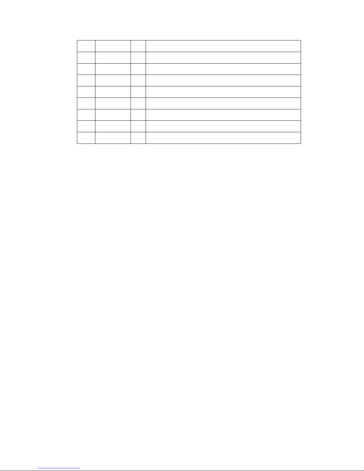
7 FAIL O Determination FAIL
8 HV-ON O High voltage output in progress
9 GND --- Chassis Ground
10 TRIG I Test trigger
11 ABORT I Test abortion
12 RESET I Reset your machine
13 +5V --- DC +5V output
14 +12V --- DC +12Voutput
15 COM --- Circuit common terminal
Use description:
PIN1-PIN8 is a collector open output without any voltage or signal. Current passing
through the connector must be less than 50mA.
(1) TRIG (Pin10): Functions the same as the TEST key in the front panel when short
circuited with Pin15 (COM)
(2) ABORT (Pin11): Functions the same as the ABORT key in the front panel when
short circuited with Pin15 (COM)
(3) PASS (Pin6): Conduct with Pin15 (COM) when the DUT is determined to PASS by
your machine
(4) FAIL (Pin7): Conduct with Pin15 (COM) when the DUT is determined to FAIL by
your machine
(5) TESTING (Pin5): Conduct with Pin15 (COM) when your machine is testing
(6) H.V. ON: Conduct with Pin15 (COM) when your machine is outputting high
voltage
Page 31
27
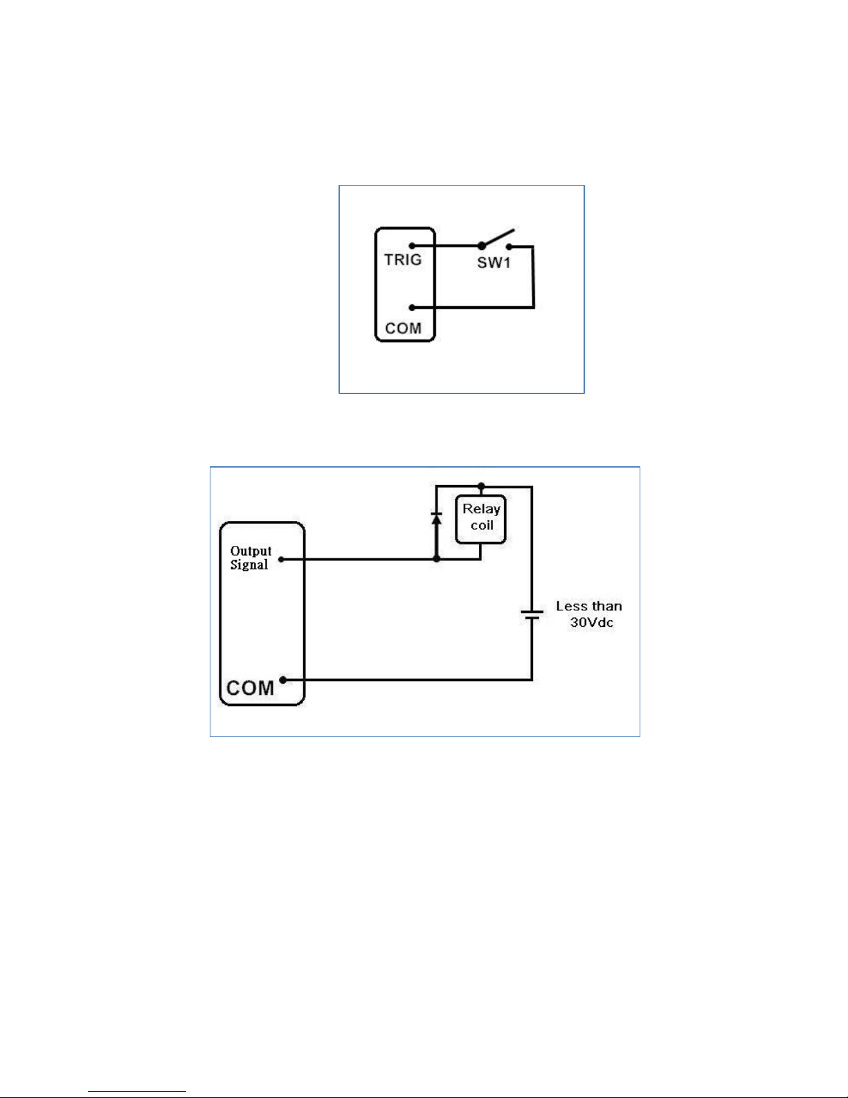
Frequent uses:
1. (Input signal) Control your machine for testing by using a normal open switch
relay
2. (Output signal) Control the relay with the output signal. Please connect the
relay coil to a regulator diode for safer application
Page 32
28
6 RS-232/USB device
6.1 RS- 232 interface
Baud Rate: Available options are 9600/19200/38400/57600/115200 and it can
be set up in the System mode
Transmission bits: 1 initial bit, 8 data bits, 1 ending bit
6.2 Command format
The RS-232 interface function of your machine is exercised by a command string
in ASCII code for remote control and setup. Each command string is composed of
the command code and its parameters, two commands are connected with a
semicolon “;”, and appended with an end code. There are two types of end code:
LF(0x0a) and CR(0x0d)+LF(0x0a).
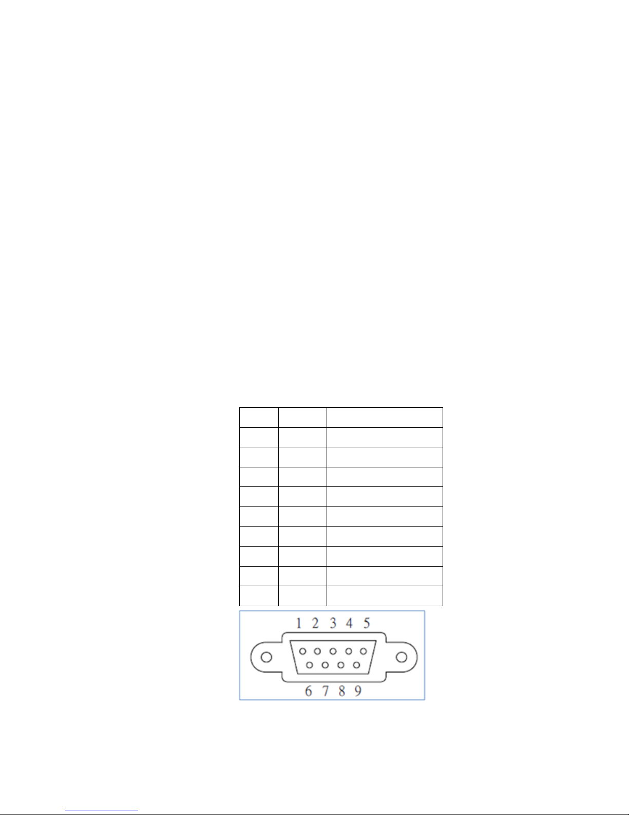
6.3 Connector
Your machine employs a 9-pin male connector with pin functions outlined in the
table below:
Pin Name Description
1 CD Reserved
2 RxD Receive data
3 TxD Transmit data
4 DTR Reserved
5 GND Ground point
6 DSR Reserved
7 RTD Reserved
8 CTS Reserved
9 RI Reserved
Page 33
29
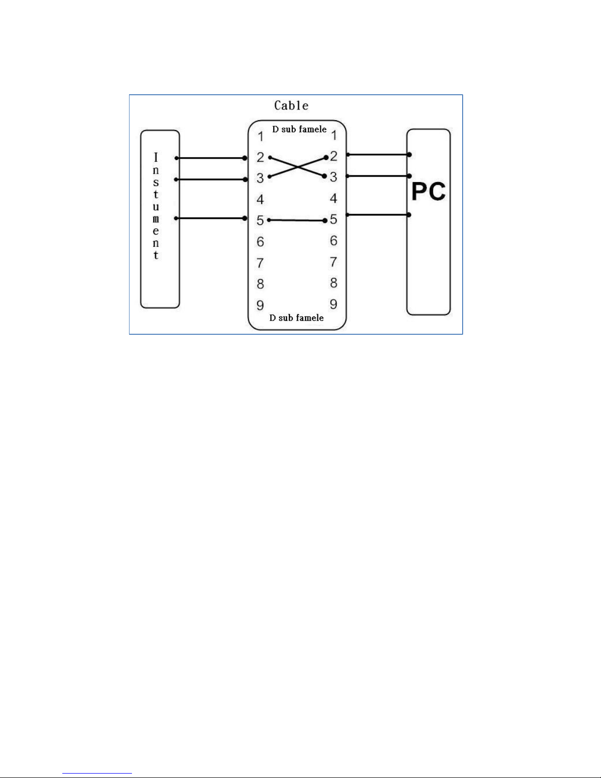
6.4 Connection cable and method
Page 34
30
6.5 USB device interface
Interface I/O USB Specification 2.0
Self-powered
Transfer rate: MAX 12Mbps(Full Speed)
Instruction string end code For receiving: LF or EOM
For transmission: LF+EOM
Vendor ID 0x1FC9
Product ID 0x811D
Page 35
31
7 Remote Command
7.1 Instruction summary
Common command
*CLS
*IDN?
*OPC
*OPC?
*OPT?
*RCL
*SAV
SCPI command
:CONFigure :KLOCk <ON , OFF, 1, 0>
:ALARm <ALL,PASS, FAIL,OFF>
:PHOLd <50ms,100ms,500ms,1s,2s,5s,INFinity>
:TGWAit <NRf>
:TMODe <SINGLE,MULTI>
:TMODe :MULT i :TSOUrce <AUTO,TRIG>
:TMODe :MULT i :BREAk <FAIL,OFF>
:TMODe :MULT i :SIGNal <EACH,TOTAL>
:EDIT :STEP <numeric>
:FUNCtion <ACW,DCW,IR>
:VOLTa ge <NRf>
:FREQuency <NRf>
:HILImit <NRf>
:LOLImit <NRf>
:RAMP <NRf>
:DWELl <NRf>
:CHANnel :POSItive <numeric>
:CHANnel :NEGAtive <numeric>
:CHANnel :CLOSe <numeric>
:ARC <numeric>
:OFFSet <NRf>
Page 36
32
:OPEN <NRf>
:IR :DELAy <NRf>
: STEP : COUNt?
: STEP : DELete <numeric>
: STEP : ADD <numeric>
: STEP : CONDition <numeric>
:MEASure :VOLTage?
:CURREnt?
:RESistance?
:TIME?
:OPERation :STEP <numeric>
:FILE?
:RESU?
:STAR
:STOP
:SYSTem :AUREply <ON , OFF, 1, 0>
:KYSOund <ON , OFF, 1, 0>
:ALARm [:VOLUme] :PASS <numeric>
:ALARm [:VOLUme] :FAIL <numeric>
:ERROr?
:TEST :ABORt
:EXECute
Page 37
33
7.2 Command description
Common command
Command Function
*CLS Clears all the registers
*IDN? Read the basic device data including the manufacturer, model,
serial number, firmware release and output in comma delimited
format
*OPC Operation completion command
*OPC? Query operation completion command: Return value 1 if operation
completed; otherwise return value 0
*OPT? Query whether the device is optional
*RCL Command for reading the machine's internal files with the
parameter of the file name in ASCII code, e.g. command “*RLC
26983877” means reading the file with the name “26983877”
*SAV Command for saving the current settings in a new file with the file
name in ASCII code, e.g. command “*SAV 26984089” means saving
current settings in file with name “26984089”
SCPI command
: CONFigure: KLOCk<ON , OFF, 1, 0>
This command locks or unlocks the keyboard
Example: CONF: KLOC ON
Example description: Locks the keyboard
Example: CONF: KLOC? Return value: 1 <enabling>
: CONFigure: ALARm<ALL,PASS, FAIL,OFF>
This command sets up an alert mode
Example: CONF: ALAR FAIL
Example description: Alert for FAIL determination results
Example: CONF: ALARm? Return value: FAIL <Alert for FAIL>
: CONFigure: PHOLd<50ms,100ms,500ms,1s,2s,5s,INFinity>
This command sets up the retaining time for PASS display
Example: CONF: PHOL 100ms
Example description: Set up PASS display time to 100mS
Example: CONF: PHOLd? Return value: +1.00000E-01 <100ms>
Page 38
34
: CONFigure: TGWAit<NRF>
This command sets up the test wait time after a trigger
Example: CONF: TGWA 500mS
Example description: Set up wait time after trigger to 500mS
Example: CONF: TGWA? Return value: +5.00000E-01 <500ms>
: CONFigure: TMODe<SINGLE,MULTI>
This command sets up the test mode
Example: CONF: TMOD MU LTI
Example description: Set up test mode to multi-step test
Example: CONF: TMOD? Return value: MULTI <multi-step mode>
: CONFigure: TMODe: MULTi: TSOUrce<AUTO,TRIG>
This command sets up a trigger source between the steps of multi-step testing
Example: CONF: TMOD: MULT: TSOU AUTO
Example description: Set up multi-step test auto to proceed with the next step
Example: :CONF: TMOD: MULT: TSOU? Return value: AUTO <auto proceed with the
next step>
: CONFigure: TMODe: MULTi: BREAk<FAIL,OFF>
This command sets up a test source abortion for multi-step tests
Example: CONF: TMOD: MULT: BREA FAIL
Example description: Set a multi-step test to stop when any one of its steps fails
Example: CONF: TMOD: MULT: BREA? Return value: FAIL <stop when any one step
failed>
: CONFigure: TMODe: MULTi: SIGNal<EACH,TOTAL>
This command sets up a signal output method in multi-step testing
Example: CONF: TMOD: MULT: SIGN TOTAL
Example description: Set a multi-
step test to output the overall determination
signal after every step has run
Example: CONF: TMOD: MULT: SIGN? Return value: TOTAL <
output overall
determination signal>
: EDIT: STEP <numeric>
This command sets up the step for editing. The following “EDIT”
string headed
command setting up step is specified by the command, e.g. after setting step 1 to
be edited, all the following voltages or current values will be set to step 1. To edit
step 2, it is necessary to switch to step 2 first (: EDIT: STEP 2).
Page 39
35
Example: EDIT: STEP 1
Example description: Set to edit step 1
Example: EDIT: STEP? Return value: 1 <step 1>
: EDIT: : FUNCtion< ACW,DCW,IR >
This command sets up the test items
Example: EDIT: FUNC ACW
Example description: Set the test item to ACW
Example: EDIT: FUNC? Return value: ACW
: EDIT: VOLTage<NRf>
This command sets up the test voltage
Example: EDIT: VOLT 1kV
Example description: Set the test voltage to 1kV
Example: EDIT: VOLT? Return value: +1.00000E+02 <1kV>
: EDIT: FREQuency<NRf>
This command sets up the frequency of test AC current
Example: EDIT: FREQ 50HZ
Example description: Set the frequency of test AC current to 50Hz.
Example: EDIT: ACW: FREQ? Return value: +5.00000E+01 <50Hz>
: EDIT: HILImit<NRf>
This command sets up the upper determination limit
Example: EDIT: HILI 1mA
Example description: Set the upper determination limit to 1mA
Example: EDIT: HILI? Return value: +1.00000E-03 <1mA>
: EDIT: LOLImit<NRf>
This command sets up the lower determination limit
Example: EDIT: LOLI 0.5mA
Example description: Set the lower determination limit to 0.5mA
Example: EDIT: LOLI? Return value: +5.00000E-04 <0.5mA>
: EDIT: RAMP <NRf>
This command sets up the voltage rising time
Example: EDIT: RAMP 0.5s
Example description: Set the voltage rising time to 0.5s
Example: EDIT: RAMP? Return value: +5.00000E-01 <0.5s>
: EDIT: DWELl<NRf>
Page 40
36
This command sets up the test time
Example: EDIT: DWEL 1s
Example description: Set the test time to 1s
Example: EDIT: DWEL? Return value: +1.00000E+00 <1s>
: EDIT: CHANnel : POSItive< numeric ><Invalid for model 7630>
This command sets up the high voltage output channel
Example: EDIT: CHAN: POSI 1,2,3,4
Example description: Set the high voltage output channel to 1, 2, 3, 4
Example: EDIT: CHAN: POSI? Return value: 1,2,3,4
: EDIT: CHANnel : NEGAtive< numeric ><Invalid for model 7630>
This command sets up the low voltage output channel
Example: EDIT: CHAN: NEGA 5,6,7,8
Example description: Set the low voltage output channel to 5, 6, 7, 8
Example: EDIT: CHAN: NEGA? Return value: 5,6,7,8
: EDIT: CHANnel : CLOSe< numeric >< Invalid for model 7630>
This command sets up the closed channel (channels without any output)
Example: EDIT: CHAN: CLOS 1,5
Example description: Set the channel 1 and 5 close
Example: EDIT: CHAN: CLOS? Return value: 1,5
: EDIT: ARC < numeric >
This command detects the arc sensitivity settings
Example: EDIT: ARC 5
Example description: Set the arc sensitivity to 5
Example: EDIT: ARC? Return value: 5
: EDIT: OFFSet<NRf>
This command sets up the reset deduction value
Example: EDIT: OFFS 0.002mA
Example description: Set up the reset deduction value to 0.002mA
Example: EDIT: OFFS? Return value: +2.00000E-06 <0.002mA>
:EDIT: OPEN <NRf>
This command sets the sensitivity for open circuit detection
Example: EDIT: OPEN 200
Example description: Sets the open circuit detection sensitivity to 200
Example: EDIT: OPEN?Return data: +2.00000E+2 <200>
Page 41
37
: EDIT: IR: DELAy<NRf>
This command sets up the IR delay determination time
Example: EDIT: IR: DELA 0.1s
Example description: Set up the IR delay determination time to 0.1S
Example: EDIT: IR: DELA? Return value: +1.00000E-01 <0.1s>
: EDIT: STEP: COUNt?
This command queries the number of test steps
Example: EDIT: STEP: COUN? Return value: 2 <this file contains 2 steps>
: EDIT: STEP: DEL < numeric >
This command deletes a test step
Example: EDIT: STEP: DEL 2
Example description: Delete test step STEP2
: EDIT: STEP: ADD < numeric >
This command adds a test step
Example: EDIT: STEP: ADD 2
Example description: Add test step STEP2
: EDIT: STEP: CONDition? < numeric >
This command queries the test step conditions
Example: EDIT: STEP: COND? 2 Example description: Query test conditions of step 2
Return value: ACW,1.00kV,50HZ,26.00mA, 0.00mA, 0.1s, 1.0s,0, 0.00mA,OFF.
Sequence of conditions: test item, voltage, frequency, upper limit, lower limit, rising
time, test time, arc sensitivity, reset deduction value, determination delay time
: MEASure: VOLTage?
This command queries the current voltage measurement
Example: MEAS: VOLT? Return value: +1.00000E+02 <1kV>
: MEASure: CURREnt?
This command queries the current measurement now
Example: MEAS: CURR? Return value: +2.00000E-06 <0.002mA>
: MEASure: RESistance?
This command queries the current resistance measurement
Example: MEAS: RES? Return value: +1.20000E+10 <12G>
: MEASure: TIME?
This command queries the test time elapsed up to now
Example: MEAS: TIME? Return value: +1.0000E+0 <1S>
Page 42
38
: OPERation: STEP <numeric>
This command selects the test step: desired test step for single-step test and the
first step for multi-step test
Example: OPER: STEP 2
Example description: Select the test step STEP2
: OPERation: STEP? Return value: 2 <2ndSTEP>
OPERation:FILE?
This command queries the current file name
Example:OPER:FILE? Return data: 26983877 <
file nameis
26983877>
: RESUlt?
This command queries the test results
Example: RESU? Return value: 01,+9.01235E+00,+7.52562E-07,+1.19756E+07,2
with contents in the following sequence: test step ID, voltage measurement,
current measurement, resistance measurement, determination results
where determination results are predefined codes with the meanings defined in the
table below:
Code Description
1 Test aborted
2 Determination PASS
3 Measurement value over upper limit
(determination FAIL)
4 Measurement value below lower limit
(determination FAIL)
5 Arc detection (determination FAIL)
6 Breaking point voltage (determination FAIL)
7 Voltage error (the difference between the
measured voltage and the voltage set is too
great)
8 Open circuit error
: STAR t
This command starts a test which functions the same as the TEST key in the front
panel
Example: STARt.
Page 43
39
: STOP
This command stops a test which functions the same as the ABORT key in the front
panel
Example: STOP.
: SYSTem: AUREply<ON , OFF, 1, 0>
This command sets up the auto reply function of RS-232
Example: SYST: AURE ON
Example description: Enable auto reply function of RS-232
Example: SYST: AURE? Return value: ON
: SYSTem: KYSOund<ON , OFF, 1, 0>
This command sets up the key sound
Example: SYST: KYSO ON
Example description: Enable key sound function
Example: SYST: KYSO? Return value: ON
: SYSTem: ALARm [: VOLUme]: PASS < numeric>
This command sets up the volume of PASS alert
Example: SYST: ALAR: PASS 1
Example description: Set the volume of PASS alert to1
Example: SYST: ALAR: PASS? Return value: 1
: SYSTem: ALARm [: VOLUme]: FAIL< numeric>
This command sets up the volume of FAIL alert
Example: SYST: ALAR: FAIL 5
Example description: Set the volume of FAIL alert to5
Example: SYST: ALAR: FAIL? Return value: 5
:SYSTem:ERROr?
This command queries the error messages queued
Please refer to Appendix 1 for the returned error message
Example: SYST:ERRO? Return data:0,”No error”
means there are no error
messages in queue
: TEST: EXECute
This command starts test which functions the same as the TEST key in front panel
Example: TEST: EXEC
: TEST: ABORt
This command stops a test which functions the same as the ABORT key in the front
Page 44

40
panel
Example: TEST: ABOR
Page 45
41
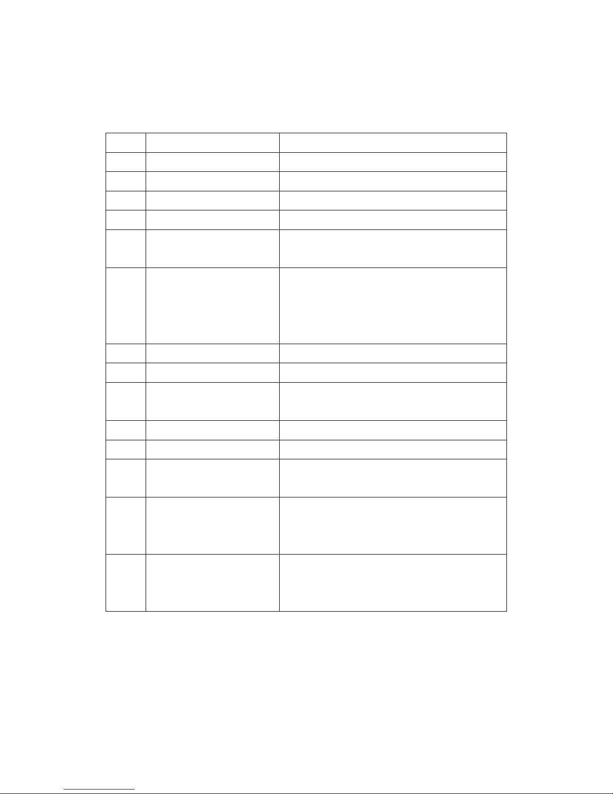
Appendix 1Error message
-100 Command error Command error
-102 Syntax error Syntax error
-103 Invalid separator Invalid separator found in the command string
-108 Parameter not allowed Received parameter that is not allowed
-109 Missing parameter Missing parameter
-112 Program mnemonic too
long
The program mnemonic exceeded 12
characters
-113 Undefined header(query a
command only command
or query command
missing '?'
Undefined header received
-141 Invalid character data Invalid character data received
-211 Trigger ignored No acceptable triggering status
-221 Settings conflict Conflict between command and device status
and cannot be executed
-222 Data out of range Parameter value exceeded allowable range
-223 Too much data Command exceeded 64 characters
-292 Reference name does not
exist
Specified name does not exist
-410 Query interrupted Query interrupted. This is when a second
query command was received when data was
not yet returned for the first query command.
-420 Query unterminate This is when the output queued data command
was received but there is no data in the output
queue
 Loading...