

Page 1

7110 / 7120
Single-Phase Power Meter
User Manual
Version: 1.01
Issued Date: Sep 2015
Page 2

1
+ Safety Instructions
Pay careful attention to all safety instructions below when operating or
maintaining the device. Disregarding these instructions and other warnings
detailed in this manual constitutes a severe violation of the design,
manufacture and operating safety standards of this device.
+ Maintenance Instructions
Operators must not remove the protective covers from the instruments. A
qualified maintenance technician must perform all internal parts replacements
or internal calibrations. Never replace any part while the power cord is plugged
in. In special circumstances, dangerous voltages may still be present within the
device after the power supply cord had been disconnected. Disconnect the
power supply and take any necessary measures to discharge electricity before
touching internal components to prevent injury.
+ Earthing the Instrument(s)
Earth all instrument power sources to minimize risks of electrical shock.
+ Never Perform Maintenance or Internal Calibration Work
Alone
Never perform internal device maintenance or internal calibration work by
yourself.
+ Never Replace Parts Yourself or Modify Device Functions or
Structure
Never install surrogate parts onto the machine or undertake any device
modifications yourself without the express permission of Microtest, as you may
increase the levels of danger associated with the device or damage the device.
Please return any malfunctioning instruments to Microtest for professional
repairs guaranteeing the device's continued safety.
+ Product Warranty
Microtest provides a quality guarantee for this product for one year from the
dispatch date of the product; however, warranty life may be different for special
parts or different product specifications. Microtest will take responsibility for all
maintenance and replacement of products found to have an actual defect
during the life of the warranty (Microtest will determine the nature of the defect).
Microtest guarantees that all software and hardware designated for use with
Page 3

2015/7/07 Version
2
instruments can be used immediately upon installation. Microtest does not
guarantee that instrument software and/or hardware will not disconnect or
produce errors during operation.
+ Product Warranty Scope
The above guarantees and warranty do not apply if a customer has failed to
use the product correctly, has modified or repaired the device or replaced parts
without permission from Microtest, has misused the product, or has installed or
repaired the product in an environment that does not meet the specified
conditions.
Microtest Corporation reserves all rights.
Declaration: Microtest Corporation reserves the rights to modify this
manual without notification of any changes or modifications.
Page 4

2015/7/07 Version
3
Chapter 1 Cautions .................................................................................... 5
Section 1.1 Safety Labels ............................................................................... 5
Section 1.2 Never modify the device or perform internal calibrations
yourself. ........................................................................................ 5
Section 1.3 Static Electricity ............................................................................ 5
Section 1.4 Earthing ......................................................................................... 6
Section 1.5 Power Supply ............................................................................... 6
Section 1.6 Warming-Up ................................................................................. 6
Section 1.7 Device Malfunctions .................................................................... 6
Section 1.8 After Testing ................................................................................. 6
Section 1.9 Installation and Storage .............................................................. 7
Section 1.10 Emergency Measures ................................................................. 7
Chapter 2 Foreword ................................................................................... 8
Section 2.1 Features ........................................................................................ 8
Section 2.2 Measuring Functions .................................................................. 9
Section 2.3 Function Flow-Chart .................................................................... 9
Chapter 3 Wiring ....................................................................................... 10
Section 3.1 Connecting to the Power Supply and Testing Items ............ 10
Section 3.2 F71201-Exclusive Jig Internal Measuring Wiring
Schematic Diagram ................................................................... 11
Chapter 4 Operating Settings .................................................................. 12
Section 4.1 Measurement Mode .................................................................. 12
Section 4.2 Measurement range .................................................................. 13
Section 4.3 Averaging .................................................................................... 14
Section 4.4 Update Rate ............................................................................... 15
Section 4.5 Synchronization ......................................................................... 16
Section 4.6 Harmonic Operation Mode Selection ..................................... 21
Section 4.7 Start Line and Frequency Filter Function .............................. 22
Section 4.8 Set Frequency CF Value .......................................................... 24
Section 4.9 Setting 4th Display Measurement Values .............................. 25
Section 4.10 Keyboard Lock ........................................................................... 26
Section 4.11 Store/Load Panel Settings Configuration .............................. 27
Section 4.12 Set GPIB Address ..................................................................... 28
Section 4.13 Remote Control Mode .............................................................. 29
Section 4.14 Set RS232 Baud rate and Final Character............................ 30
Section 4.15 The SCALE Function ................................................................ 31
Section 4.16 Use Power Integrator ................................................................ 33
Page 5

2015/7/07 Version
4
Section 4.17 Power Supply Frequency Parameters ................................... 34
Section 4.18 Calibrate to Zero ........................................................................ 35
Section 4.19 Software Version Look-up ........................................................ 36
Section 4.20 Real time measure data storing .............................................. 37
Section 4.21 Reso Settings ............................................................................. 39
Section 4.22 Gauge Head Power Consumption Deductions ..................... 41
Chapter 5 Display Measurement Values ................................................. 42
Section 5.1 Panel Description ...................................................................... 42
Section 5.2 Measurement Items: ................................................................. 46
Section 5.3 Display A Measurement Display Area .................................... 47
Section 5.4 Display B Measurement Display Area.................................... 48
Section 5.5 Display C Measurement Display Area ................................... 49
Chapter 6 Electrical Features Specifications ......................................... 50
Chapter 7 GPIB Instruction Sets ............................................................. 64
Section 7.1 Serial Communications Specifications ................................... 64
Section 7.2 Symbols ...................................................................................... 64
Section 7.3 Commands ................................................................................. 64
Appendix…………….. ................................................................................... 85
Version…….. ................................................................................................. 85
Page 6
5
Chapter 1 Cautions
Do not use this instrument outside and avoid humid or dusty areas. Use of this
instrument in an improper setting can increase the risk of electrical shock.
Carefully read all safety instructions before using the device to prevent
accidents due to misuse.
Section 1.1 Safety Labels
The following safety labels may appear in this user manual and
on the device itself.
Caution: Carefully read the user manual for detailed information.
Earthing Required: Check that this terminal is earthed before
operating the device to prevent electrical shocks due to leakage or
contact with the housing.
: Improper use of the device may result in instrument or testing
object malfunctions.
: Improper use of the device may result in injury or death.
Section 1.2 Never modify the device or perform
internal calibrations yourself.
Never install surrogate parts onto the machine or undertake any device
modifications and internal calibrations yourself without the express
permission of Microtest, as you may increase the levels of danger
associated with the device or damage the device.
Section 1.3 Static Electricity
Keep items bearing static electricity away from the device to prevent
damage.
Page 7

2015/7/07 Version
6
Section 1.4 Earthing
A safe earthing terminal is located on the outer housing of the back panel
of the device; check that this terminal is properly earthed to prevent
contact with the housing and risk of electrical shock.
Section 1.5 Power Supply
You must use a power supply cable that meets local national
specifications and an IEC320-compatible connector to connect the cable
to the instrument. The user must check that the earth wire is properly
earthed. If a fuse is included in the power supply plug it must be a 3.15A
fuse compatible with relevant safety regulations. Always check before
use to ensure A/C power supply and voltage values are between
100V-240V @ 50/60Hz.
Section 1.6 Warming-Up
The testing device can be used normally immediately after switching the
power on, but will not meet accuracy specifications unless allowed to
warm up for 30 minutes.
Section 1.7 Device Malfunctions
Return all malfunctioning instruments to the manufacturer for
professional repair in order to ensure the accuracy and operational safety
of the instrument.
Section 1.8 After Testing
Please turn the device off at the power source if it will not be used for a
long period of time.
Page 8

2015/7/07 Version
7
Section 1.9 Installation and Storage
The device may be operated normally in temperatures of 18-28°C with up
to 80% RH. The device may not operate in conditions exceeding these
limits. The device should be stored at -20°C~70°C with up to 80% RH. In
order to ensure testing accuracy and safety, avoid installing the device
anywhere it would be exposed to direct sunlight, extreme heat, extreme
humidity, vibration frequencies, dust, or unstable power grids.
Section 1.10 Emergency Measures
Switch off the power supply and disconnect the power supply cable in the
event of electrical shock, test item combustion and device combustion.
Page 9

2015/7/07 Version
8
Chapter 2 Foreword
Section 2.1 Features
1. 0.1% Base Accuracy, Up to 160% AC Voltage Range, Current Crest
Factor (cf) Settings of 3 or 9. CF3: Up to 215% AC Current Range; CF9:
Up to 645% AC Current Range; CF3: Up to 344% Power Range; CF9: Up
to 1,032% Power Range.
2. With Erp Lot6 2013 Standby and off-mode power loss Standby Power
Consumption Gauge.
3. Continuous Sampling design; AC 50HZ/60HZ base sampling rate of
100KSPS/120KSPS; Standby Power Consumption Gauge Precision of up
to 0.001W for compatible high/low frequency electronic products.
4. Measures: AC/DC voltage current, active power (W), variance (var),
apparent power (VA), power factor (PF), VI angle (DEG), voltage current
crest factor (CF), voltage and current frequencies (Hz), voltage
peak-to-peak (VP-P), current peak-to-peak (IP-P), total harmonic
distortion (THD), harmonic voltage/current analysis at any one of 50
stages, instantaneous current and more.
5. Double CPU Design for Faster Measurements.
6. Easy-to-use Operating Panel.
7. Fast Automatic Transmission - 1 range/0.02 sec @ 50Hz.
8. Current Measuring Circuit utilizes a highly reliable vehicle relay design
and features a long service life.
9. Total harmonic/single-stage distortion can be measured at up to 50
stages.
10. Can connect high-amperage current transformers to measure large
currents
11. Fast and Accurate Measurements.
12. Can connect standard RS232/GPIB cables (one at a time).
13. Suitable for both large and small power measurements and can measure
0.1W standby consumption with analysis precision of 0.001W.
14. High-capacity built-in memory capable of recording 1,000 units of
measurement data for long-term power analysis over time.
15. Comes with voltage meter micro-consumption adjustments.
Page 10
2015/7/07 Version
9
Section 2.2 Measuring Functions
Parameter Scope
Testing Scope
Vrms/Vdc
0.1V~800V
Irms/Idc
0.2mA~20A
W
0.01W~16KW
PF
0.0000~±1.0000
Deg
-180.00~+180.00
THD
0.01%~999.99%
Hz
15Hz~100kHz
Section 2.3 Function Flow-Chart
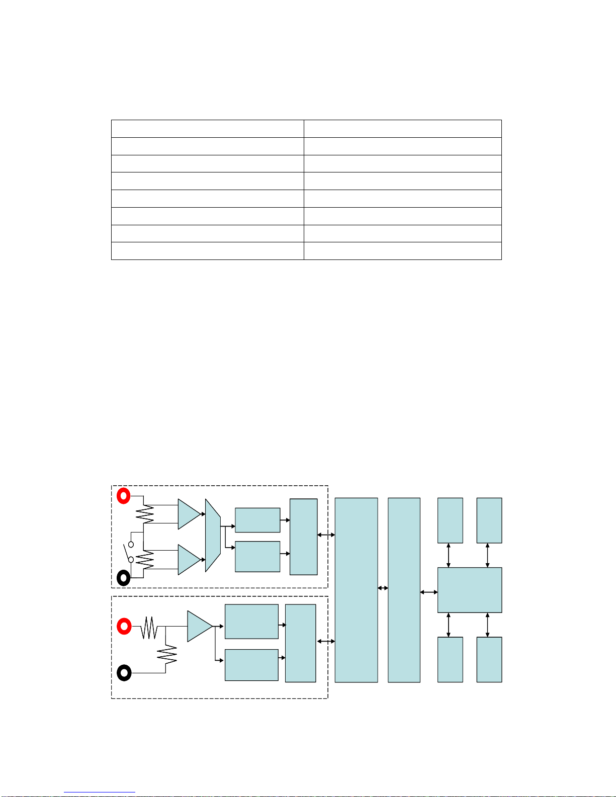
7120 Internal Flow Chart:
7120 Voltage channel input resistance is 1M ohm, voltage can be input
directly for testing or measured with a standard attenuation sonde. Current
measurement terminal uses 0.0025Ω and 0.25Ω precision shunts to directly
measure currents between 0.0002A-20A, and an external CT can be used to
measure larger currents. Measurement and sampling processes use
independent digital signal processors and measurement results are saved in a
dual-port memory before being transmitted to the LED 7-stage display panel by
the CPU, integrated, and applied via the GPIB/RS-232 and ATE systems.
ADC
ISO
ZERO phase
Cross monitor
MUX
2.5mΩ
250mΩ
ADC
ISO
ZERO phase
Cross monitor
Dual port
Memory
Black Fin
DSP
LPC 4088 CPU
GPIB RS232
KEY
7-Seg.
LED
I+
I-
V+V-1MΩ
ADC
ISO
ZERO phase
Cross monitor
MUX
2.5mΩ
250mΩ
ADC
ISO
ZERO phase
Cross monitor
Dual port
Memory
Black Fin
DSP
LPC 4088 CPU
GPIB RS232
KEY
7-Seg.
LED
I+
I-
V+V-1MΩ
Page 11
2015/7/07 Version
10
Chapter 3 Wiring
Section 3.1 Connecting to the Power Supply and
Testing Items
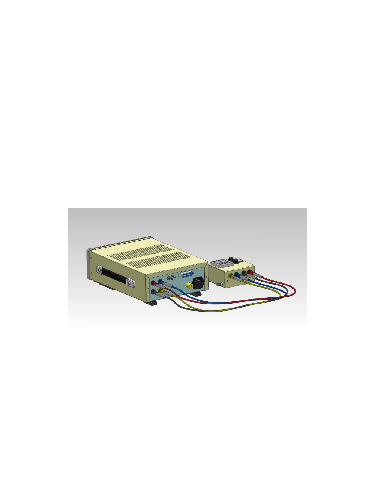
Match the colors on the terminals on the back panel to those of the
terminals above the jigs on the F71201 Test Box to connect the wires and
connect two AC power supply cables - 1 to the F71201, and one to the input
port on the 7120 Power Supply.
Plug appearances in different countries may make it necessary to use a
converter to connect the cable to the F71201 Text Box; please select an
appropriate converter for your locale.
Page 12
2015/7/07 Version
11
Section 3.2 F71201-Exclusive Jig Internal Measuring
Wiring Schematic Diagram
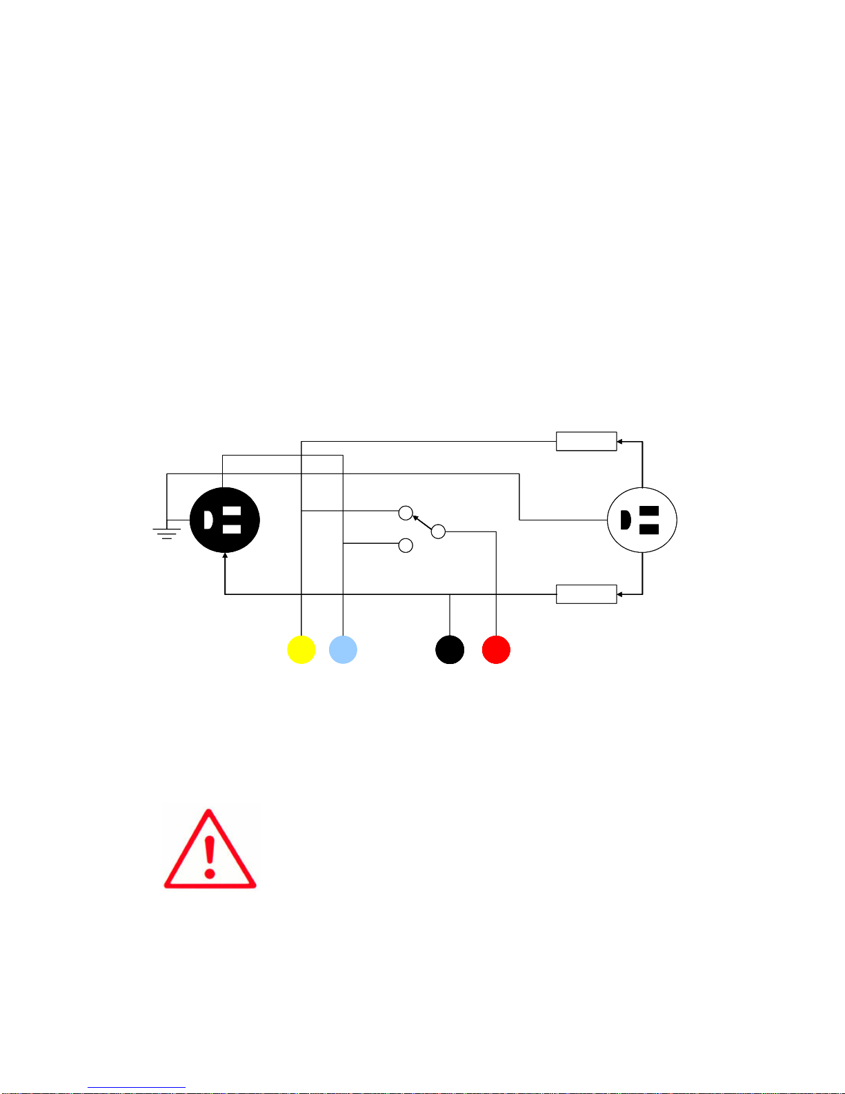
Below is a schematic diagram of the internal wiring when using the F71201
Test Box. When the switch is set to 1 the voltage measurement point will be
closer to the testing item to prevent overly low wattage measurements
resulting from voltage drops across the wiring circuit under large currents.
When the switch is set to 2 all power expended by the 7120 voltage input
internal resistor 1M Ω is subtracted from the power rate closest to 0W; this
setting is used only for measuring standby power. Determine whether to set
the switch to 1 or 2 by looking at the rate of the current of the testing object.
I+I- V+V-
Fuse
Fuse
N
L
L
N
2
1 SOURCELOAD
Voltage pick up
point
I+I- V+V-
Fuse
Fuse
N
L
L
N
2
1 SOURCELOAD
Voltage pick up
point
Caution:
Double check that the voltage and wiring at the
current input terminals are correct before connecting
to mains power to prevent power overload.
Page 13

2015/7/07 Version
12
Chapter 4 Operating Settings
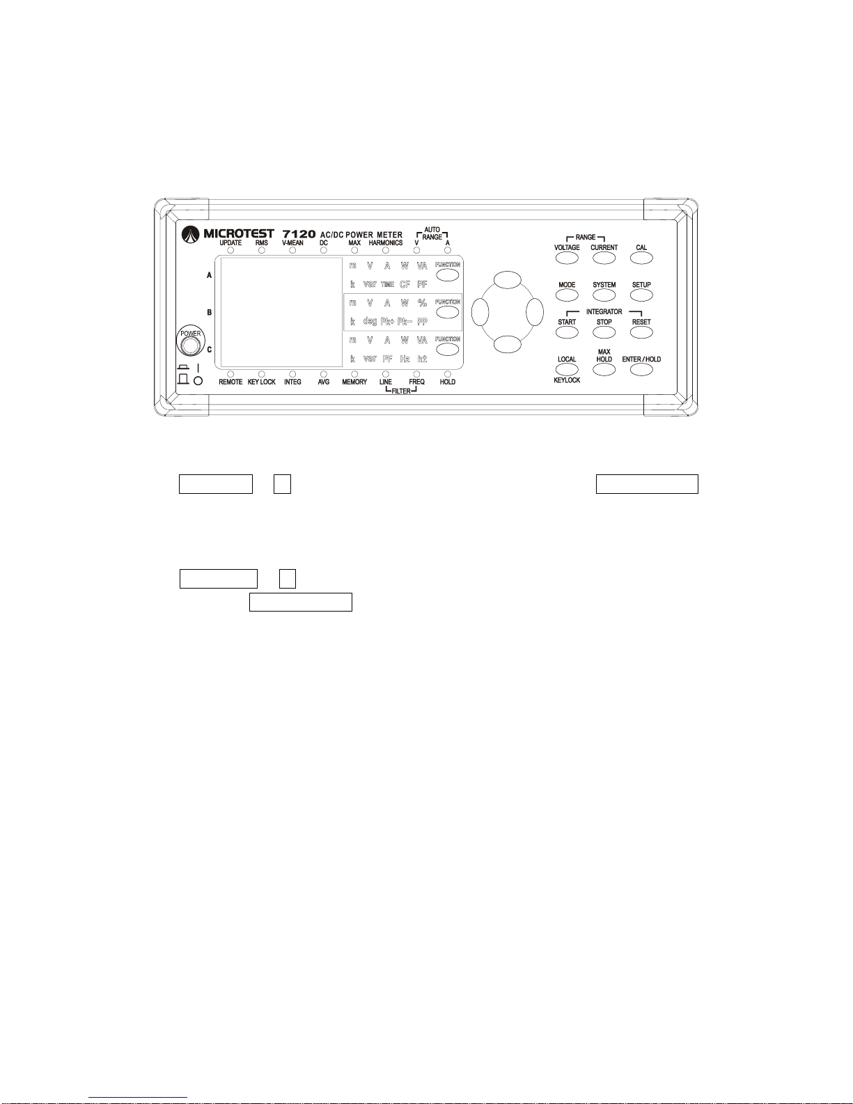
Section 4.1 Measurement Mode
Keys:
Steps:
Press
Description:
Indicator
Voltage
Current
RMS
Measured true rms value
Measured true rms value
V-MEAN
Rectified mean value
calibrated to the rms value
Measured true rms value
DC
Measured DC value obtained
by averaging input signal
Measured DC value obtained
by averaging input signal
Harmonic
Measured harmonic distortion
Measured harmonic distortion
Page 14
2015/7/07 Version
13
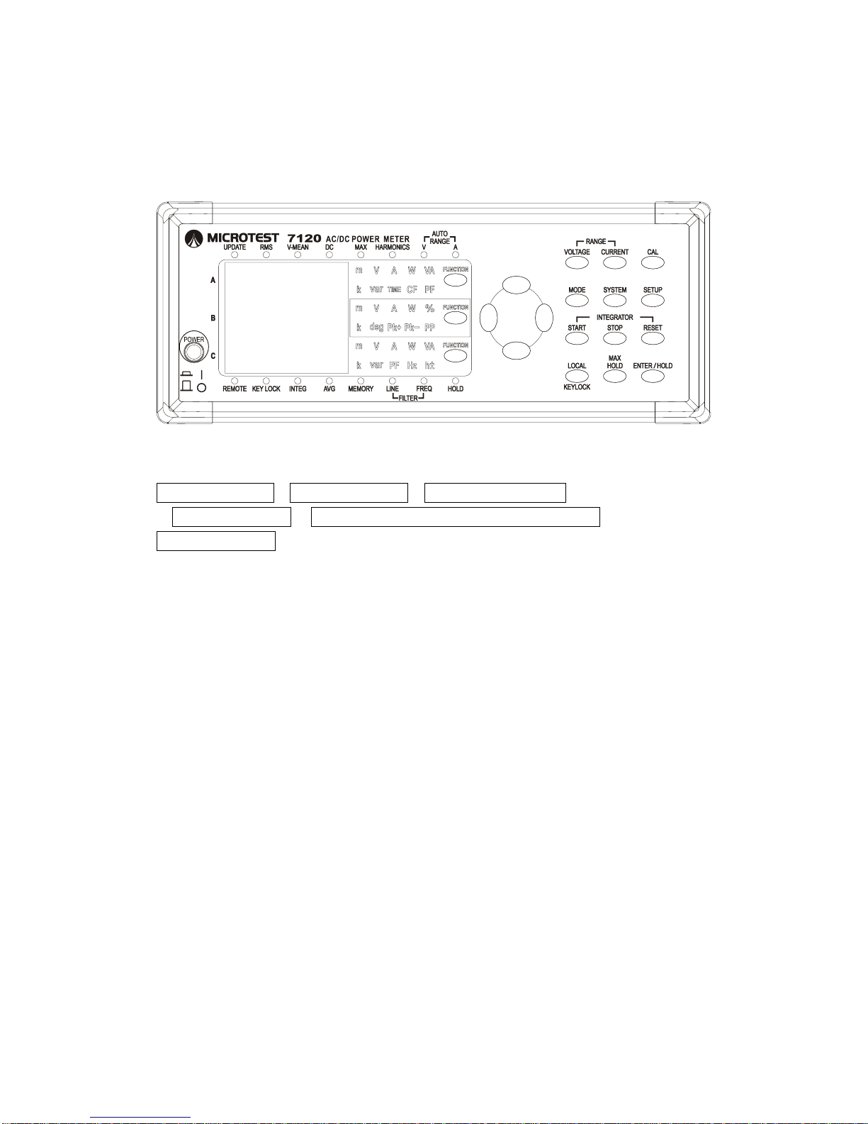
Section 4.2 Measurement range
Keys:
Steps:
Set Voltage range
1. VOLTAGE 2. ↑↓ Select 10V/30V/100V/300V/600V/AUTO 3. ENTER/HOLD
to complete voltage range selection.
Set Current Range
4. CURRENT 2. ↑↓ Select 0.01A/0.03A/0.1A/0.3A/1A/3A/10A/20A/AUTO
then press 3. ENTER/HOLD to complete current range selection.
Description:
The AUTO RANGE LED on the panel will light up when voltage or current
range are set to AUTO. Press the voltage or current key to show which
automatically selected voltage or current range is currently being used by the
device on the C Display.
1.
2.
3.
4.
Page 15
2015/7/07 Version
14
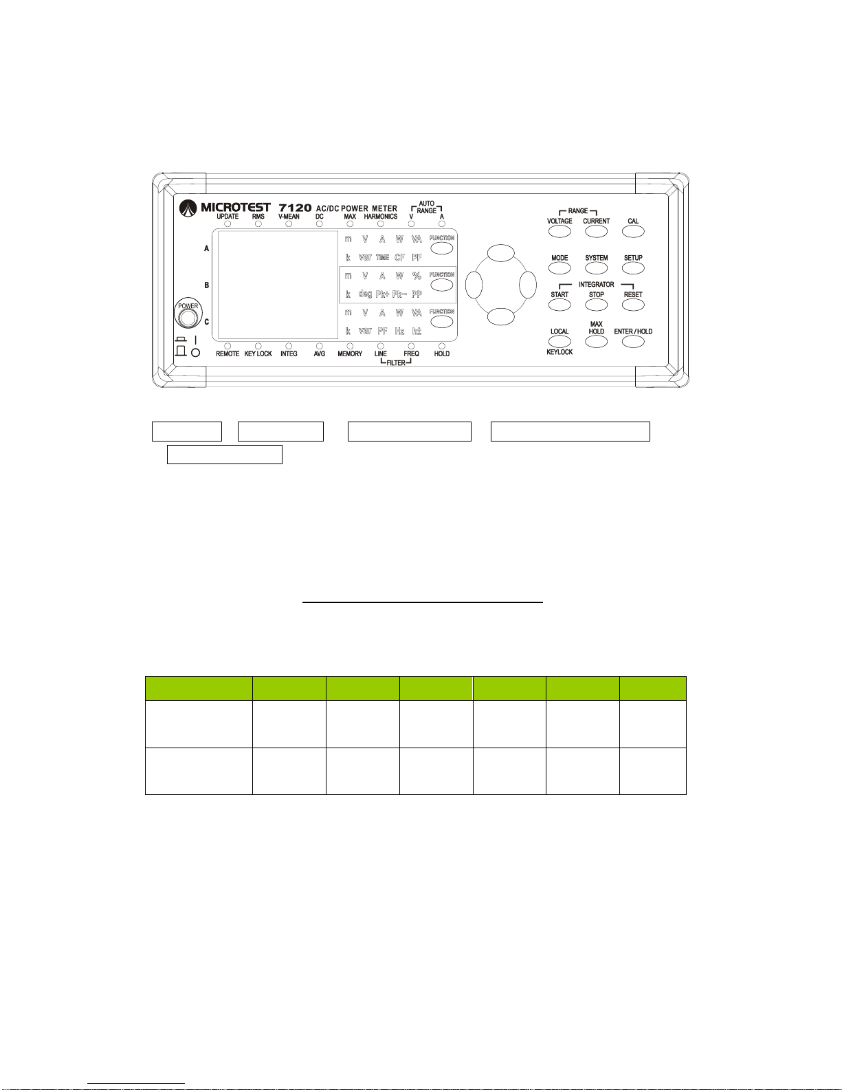
Section 4.3 Averaging
Keys:
Steps:
1.SETUP↑↓AVG2.ENTER/HOLD3.↑↓ON/OFF/FACT
2.ENTER/HOLD 3.↑↓LIN8/16/32/64/EP8/EP16/EP3/EP64
2.ENTER/HOLD
Description:
An exponential average (EP8~EP64) is calculated using the following formula:
D = D
n-1
+ (Mn – D
n-1
)/K
Where
Dn: the value at the nth display;
D
n-1
: the exponentially averaged value at the n-1th display;
Mn: the measurement value at the nth display;
K: attenuation constant
A moving average is calculated using the following formula:
D = (D
m-1
)+(D
m-2
)…(D
m-64
)/m
Where
Dm-(1~64): the moving averaged value at the m-(1~64)th display;
m = 8, when setting LIN8
m = 16, when setting LIN16
m = 32, when setting LIN32
m = 64, when setting LIN64
m: sample number
1.
2.
3.
Page 16
2015/7/07 Version
15
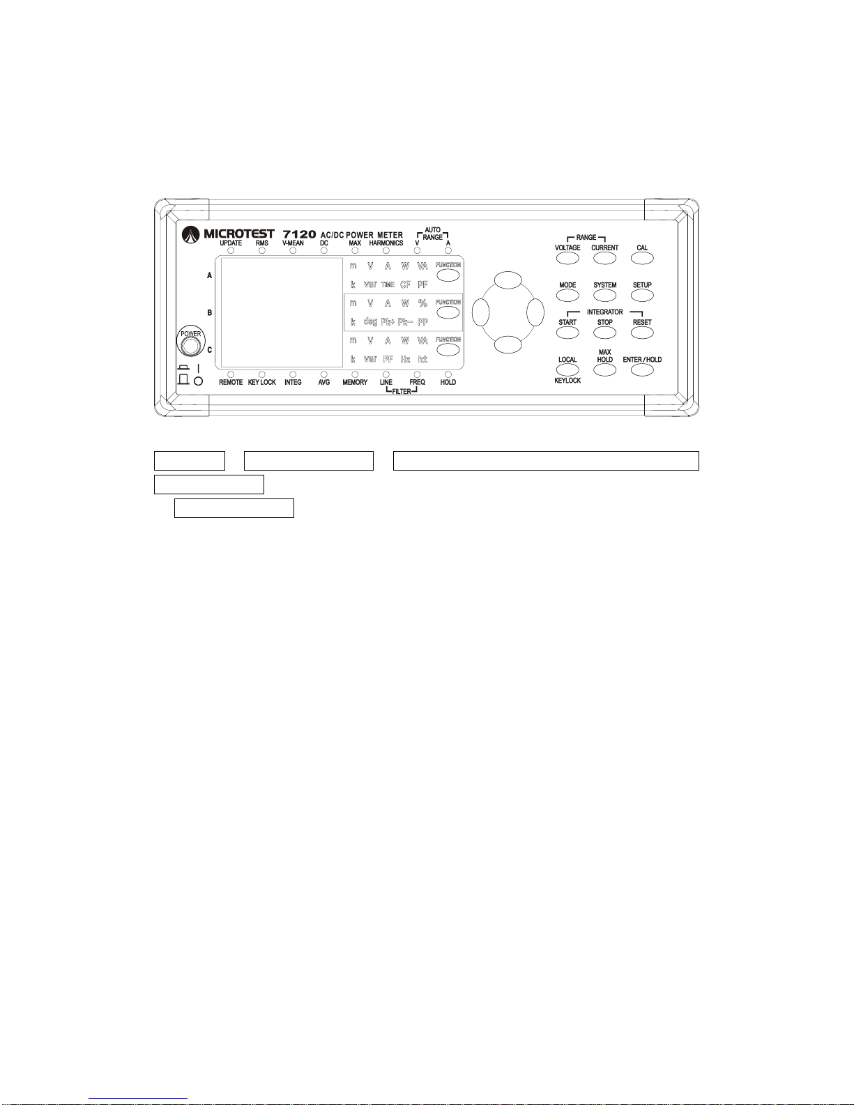
Section 4.4 Update Rate
Keys:
Steps:
1. SETUP 2. ↑↓URATE 3. ENTER/HOLD 2.↑↓ 0.1/0.25/0.5/1/2/5
3.ENTER/HOLD
Description:
The update rate defines measurement update intervals: the longer the
period set, the greater the number of sampling cycles, and the more stable the
readings. Each testing item will have its own loading characteristics - slow
down the update rate if the readings show great variation in order to obtain
more stable readings. Sampling cycles for each URATE can be found below.
In Harmonics mode, the update rate can be between .025S~5S.
AC
0.1s
0.25s
0.5s
1s
2s
5s
50Hz Mains
Power
5
10
25
50
100
250
60Hz Mains
Power
6
12
30
60
120
300
Page 17
2015/7/07 Version
16
Section 4.5 Synchronization
Keys:
Steps:
1. SETUP 2.↓↑ Select SYNC 3. Press ENTER/HOLD and use ↓↑ to select
V/A/AUTO/OFF
3. ENTER/HOLD
Description:
A: First use the current (with a frequency jitter of under 2%) as a
synchronization source, then the voltage. If both are unstable, take a fixed
sample at 200KSPS.
V: First use the voltage (with a frequency jitter of under 2%) as a
synchronization source, then the current. If both are unstable, take a fixed
sample at 200KSPS.
Auto: Automatically determine whether to use the voltage or the current as the
synchronization source (voltage >1V / Current (only use if reading >3% of
ranges). Automatic Synchronization Source Rules: Synchronize using voltage
only when voltage is stable. Synchronize using current only when current is
stable. Select the lower-frequency option if both current and voltage meet
minimum signal conditions with a jitter of less than 2%. Use a fixed 200KSPS
sample if neither the current nor voltage meets the required conditions. The
current automatic synchronization locked source will be display beneath the
Sync menu as V-Auto (voltage), A-Auto (current) or d-Auto (default fixed
sample). Only RMS/MEAN/DC are supported in Auto mode; in Harmonic mode
please set a stable and lower-frequency signal source as the base frequency.
1.
2.
3.
Page 18
2015/7/07 Version
17
Voltage >1V && Voltage Frequency Jitter < 2%
V-Sync
V-Auto
Current > 3% of range && Voltage Frequency Jitter < 2%
A-Sync
A-Auto
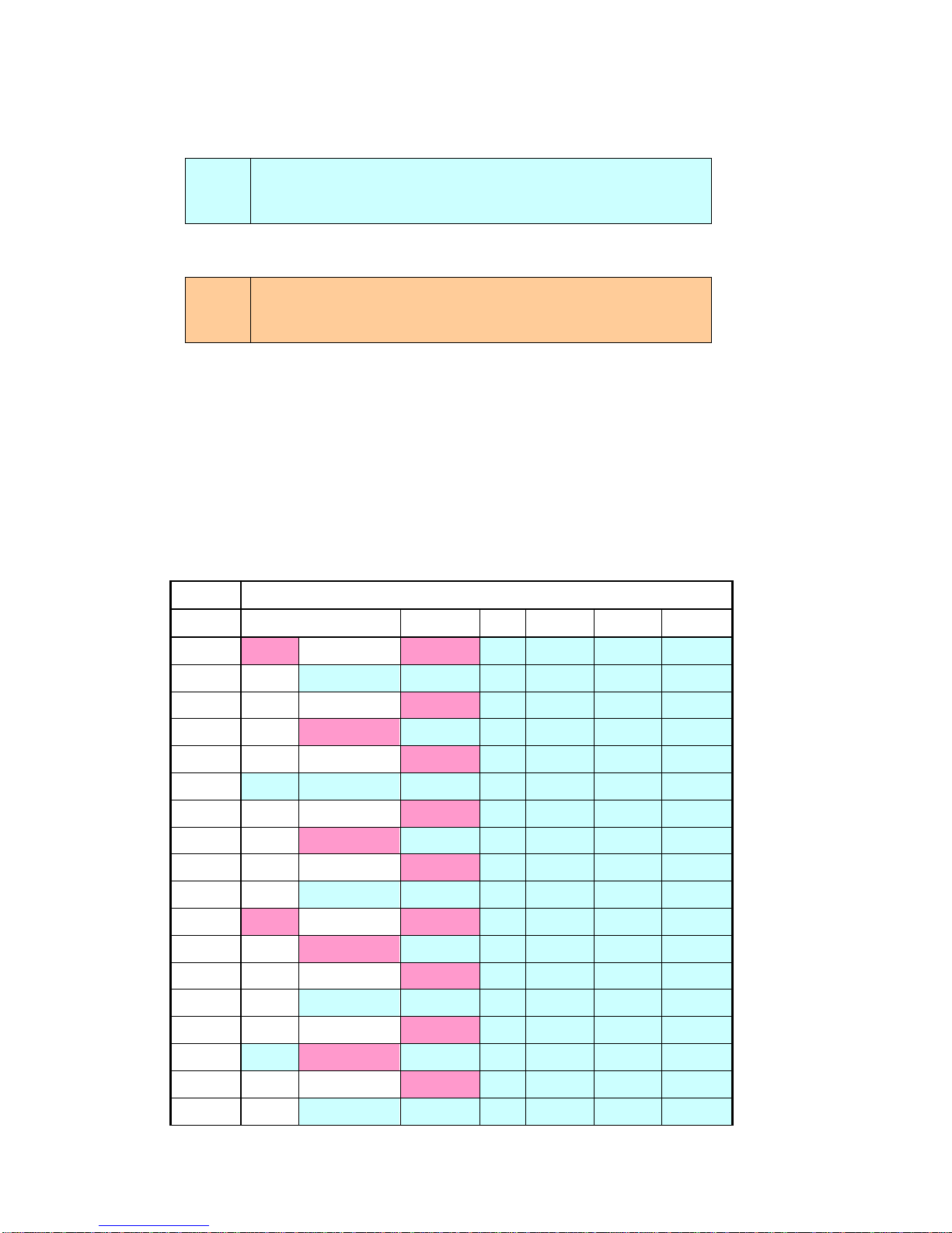
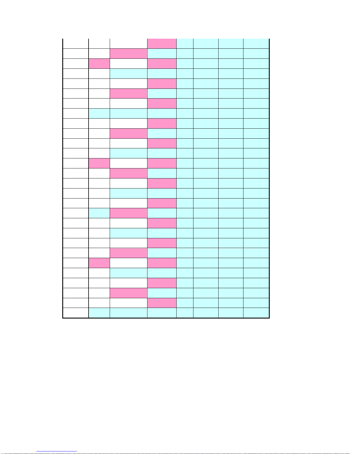
OFF: The Sync OFF option is only for capturing high-frequency surge currents.
The 7120 takes fixed ~200KSPS samples and uses different update rates to
calculate the samples. Reading stability has been reaching once the input
signals match the frequencies given in the following table at the completion of
the sampling cycle (pale blue cells); although the pink cell values also indicate
a stable reading frequency, they are only given for reference purposes as their
sampling cycle is just over half a cycle.
Update Rate (Seconds)
Freq.
0.1
0.25
0.5 1 2 5 10
15
1.5
3.75
7.5
15
30
75
150
16
1.6 4 8
16
32
80
160
17
1.7
4.25
8.5
17
34
85
170
18
1.8
4.5
9
18
36
90
180
19
1.9
4.75
9.5
19
38
95
190
20 2 5
10
20
40
100
200
21
2.1
5.25
10.5
21
42
105
210
22
2.2
5.5
11
22
44
110
220
23
2.3
5.75
11.5
23
46
115
230
24
2.4 6 12
24
48
120
240
25
2.5
6.25
12.5
25
50
125
250
26
2.6
6.5
13
26
52
130
260
27
2.7
6.75
13.5
27
54
135
270
28
2.8 7 14
28
56
140
280
29
2.9
7.25
14.5
29
58
145
290
30 3 7.5
15
30
60
150
300
31
3.1
7.75
15.5
31
62
155
310
32
3.2 8 16
32
64
160
320
Page 19
2015/7/07 Version
18
33
3.3
8.25
16.5
33
66
165
330
34
3.4
8.5
17
34
68
170
340
35
3.5
8.75
17.5
35
70
175
350
36
3.6 9 18
36
72
180
360
37
3.7
9.25
18.5
37
74
185
370
38
3.8
9.5
19
38
76
190
380
39
3.9
9.75
19.5
39
78
195
390
40 4 10
20
40
80
200
400
41
4.1
10.25
20.5
41
82
205
410
42
4.2
10.5
21
42
84
210
420
43
4.3
10.75
21.5
43
86
215
430
44
4.4
11
22
44
88
220
440
45
4.5
11.25
22.5
45
90
225
450
46
4.6
11.5
23
46
92
230
460
47
4.7
11.75
23.5
47
94
235
470
48
4.8
12
24
48
96
240
480
49
4.9
12.25
24.5
49
98
245
490
50 5 12.5
25
50
100
250
500
51
5.1
12.75
25.5
51
102
255
510
52
5.2
13
26
52
104
260
520
53
5.3
13.25
26.5
53
106
265
530
54
5.4
13.5
27
54
108
270
540
55
5.5
13.75
27.5
55
110
275
550
56
5.6
14
28
56
112
280
560
57
5.7
14.25
28.5
57
114
285
570
58
5.8
14.5
29
58
116
290
580
59
5.9
14.75
29.5
59
118
295
590
60 6 15
30
60
120
300
600
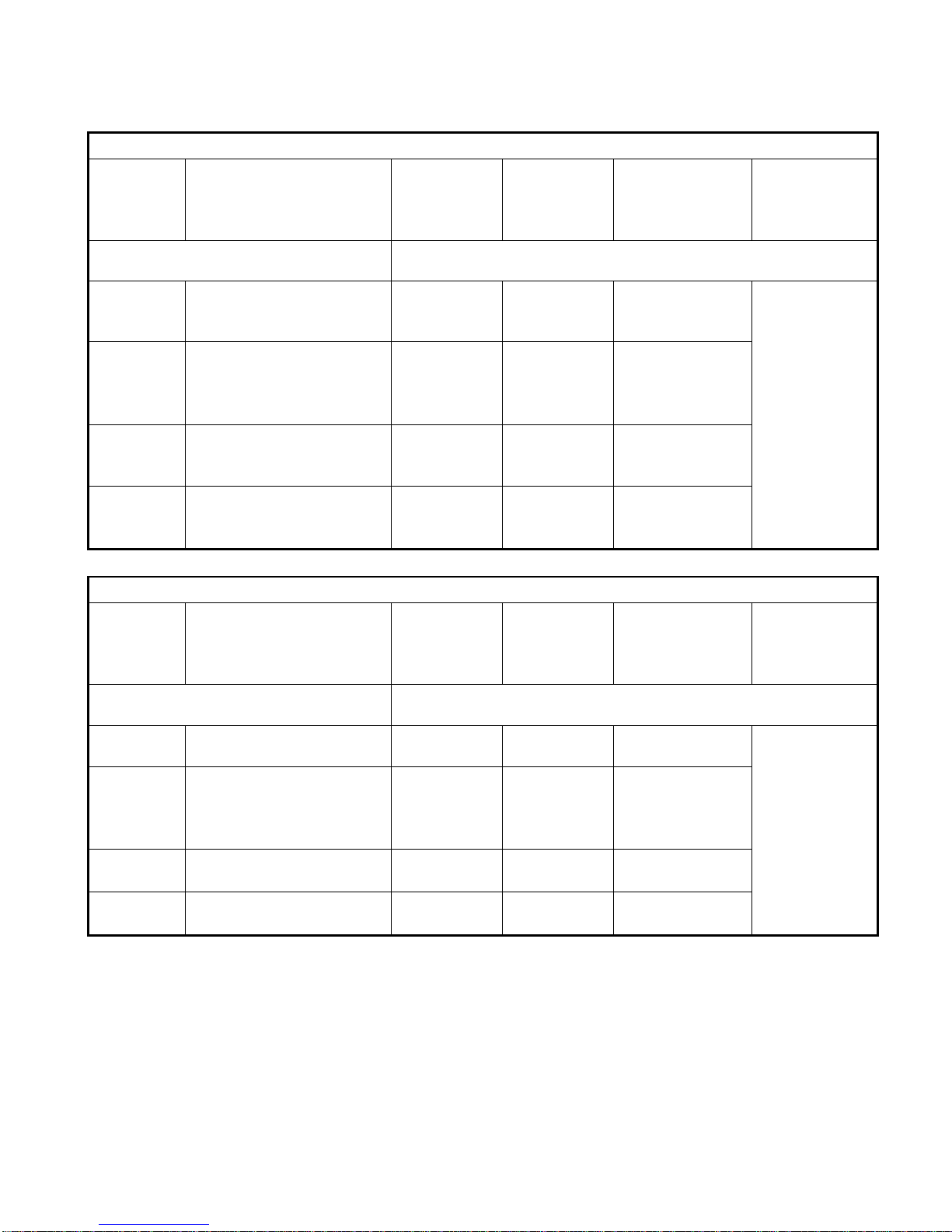
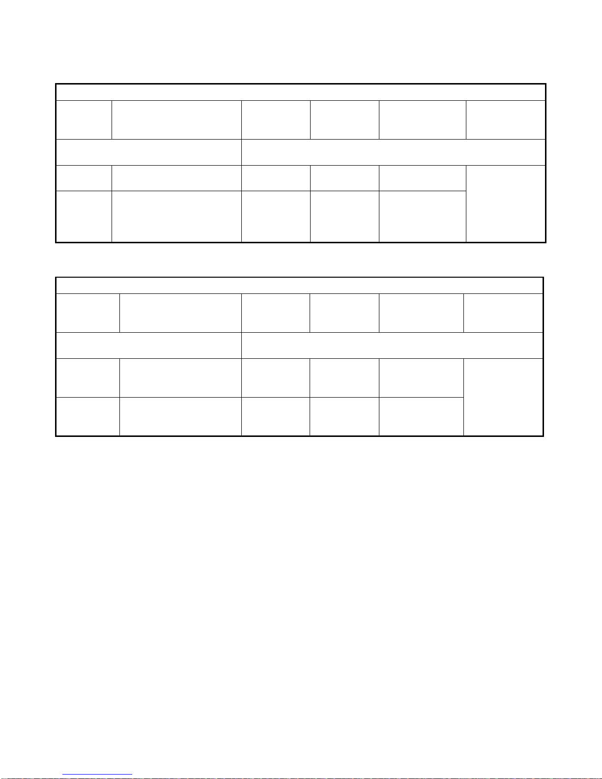
Appropriate Synchronization Sources result in Stable Readings:
The 7120 can be operated in both ordinary power mode and as an
independent ammeter, an ampere-hour meter or an independent voltmeter.
The following table gives synchronization source settings for common input
signals with a description of the synchronization rules of the 7120 in order to
help the user select the most appropriate synchronization source to obtain a
stable and accurate voltage/current/watt reading.
Page 20
2015/7/07 Version
19
RMS / DC / MEAN Power Meter Mode
Voltage
Current
Sync-V
Priority Order
(V-A-d)
Sync-A
Priority Order
(A-V-d)
Sync-Auto
(Voltage over
1V, Current over
Gear 3%)
Sync - OFF
The below are actual operating mechanisms for internal
synchronization sources.
Ο(Stable)
Χ(No Freq or Unstable)
V V V-Auto
d(default)
No
synchronization
source, use
fixed sampling
rate
Ο(Stable)
Ο(Stable)
V
A
Prioritize those
with long
periodic signals
and jitter <2%.
Χ(Unstable)
Ο(Stable)
A A A-Auto
Χ(Unstable)
Χ(No Freq or Unstable)
d(default)
d(default)
d-Auto
Harmonic Power Meter Mode
Voltage
Current
Sync-V
Selected
Only V
Sync-V
Selected
Only V
Sync-Auto
(Voltage over
1V, Current over
Gear 3%)
Sync - OFF
The below are actual operating mechanisms for internal
synchronization sources.
Ο(Stable)
Χ(No Freq or Unstable)
V
No
Measurement
V-Auto
Setting does
not exist
Ο(Stable)
Ο(Stable)
V
A
Prioritize those
with long
periodic signals
and jitter <2%.
Χ(Unstable)
Ο(Stable)
No
Measurement
A
A-Auto
Χ(Unstable)
Χ(No Freq or Unstable)
No
Measurement
No
Measurement
No
Measurement
Page 21
2015/7/07 Version
20
RMS / DC / MEAN Ammeter Mode
Voltage
Current
Sync-V
Priority Order
(V-A-d)
Sync-A
Priority Order
(A-V-d)
Sync-Auto
(Current over
Gear 3%)
Sync - OFF
The below are actual operating mechanisms for internal
synchronization sources.
Χ(Idle
Contact)
Χ(No Freq or Unstable)
d(default)
d(default)
d-Auto
d(default)
No
synchronization
source, use
fixed sampling
rate
Χ(Idle
Contact)
Ο(Stable)
A
A
Jitter must be
less than 2% for
A-Auto
RMS / DC / MEAN Voltmeter Mode
Voltage
Current
Sync-V
Priority Order
(V-A-d)
Sync-A
Priority Order
(A-V-d)
Sync-Auto
(Voltage over
1V)
Sync - OFF
The below are actual operating mechanisms for internal
synchronization sources.
Ο(Stable)
Χ(Idle Contact)
V
V
Jitter must be
less than 2% for
A-Auto
d(default)
No
synchronization
source, use
fixed sampling
rate
Χ(Unstable)
Χ(Idle Contact)
d(default)
d(default)
d-Auto
Page 22
2015/7/07 Version
21
Section 4.6 Harmonic Operation Mode Selection
Keys:
Steps:
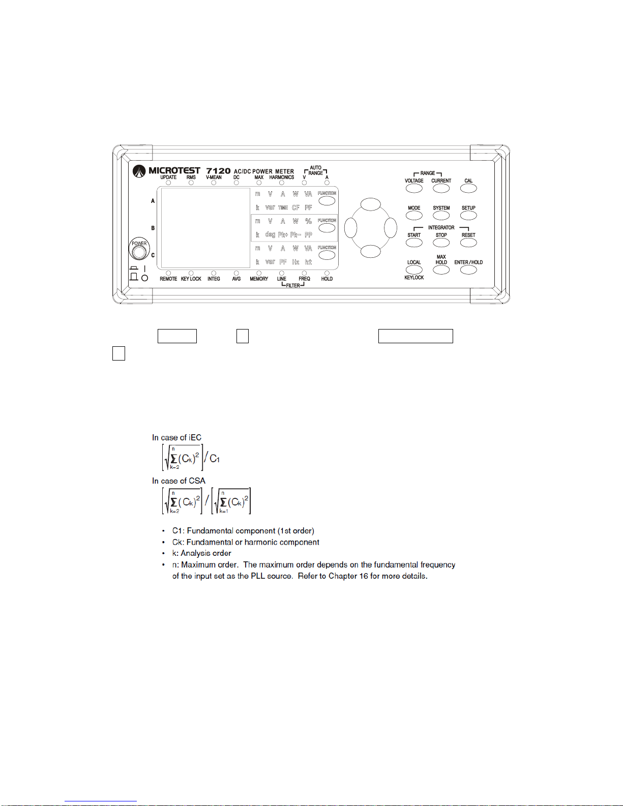
1. Press SETUP 2. Use ↑↓ to select THD and press ENTER/HOLD then use
↑↓ to select IEC or CSA
Description:
Below are the differences between IEC and CSA Total Harmonic
Distortion Ratio Definitions. The 7120 supports calculations using both.
1.
2.
3.
Page 23
2015/7/07 Version
22
Section 4.7 Start Line and Frequency Filter Function
Keys:
Steps:
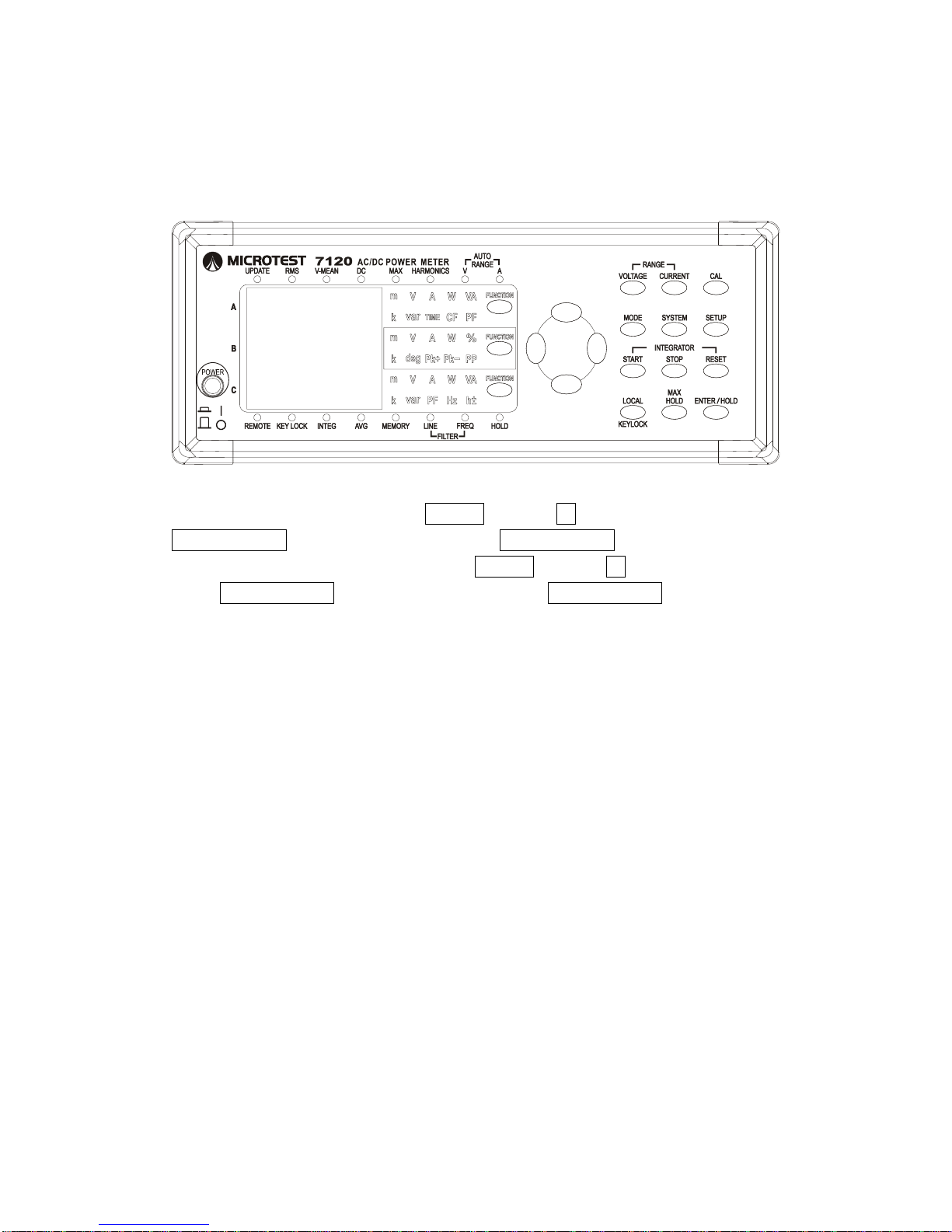
Line Filter Start/Stop: Press SETUP and use ↑↓ to select L.FILTER, press
ENTER/HOLD, select ON/OFF and press ENTER/HOLD
Frequency Filter Start/Stop: Press SETUP and use ↑↓ to select F.FILTER,
press ENTER/HOLD, select ON/OFF and press ENTER/HOLD
Line Filter Description: Interference from background noise over 500Hz can
be picked up easily and may affect low-frequency signal measuring precision
when measuring small voltages (<0.1V) or small currents (1mA). Turn this
function on to eliminate noise over 500Hz and increase precision. Use of this
function is not recommended if the current frequency of the testing item is over
66Hz. The line filter coefficients for the 7120 were designed to eliminate
high-frequency signals and allow the power meter to focus on measuring
low-frequency continuous signals. The maximum input frequency allowed by
the line filter is 16KHz.
Page 24
2015/7/07 Version
23
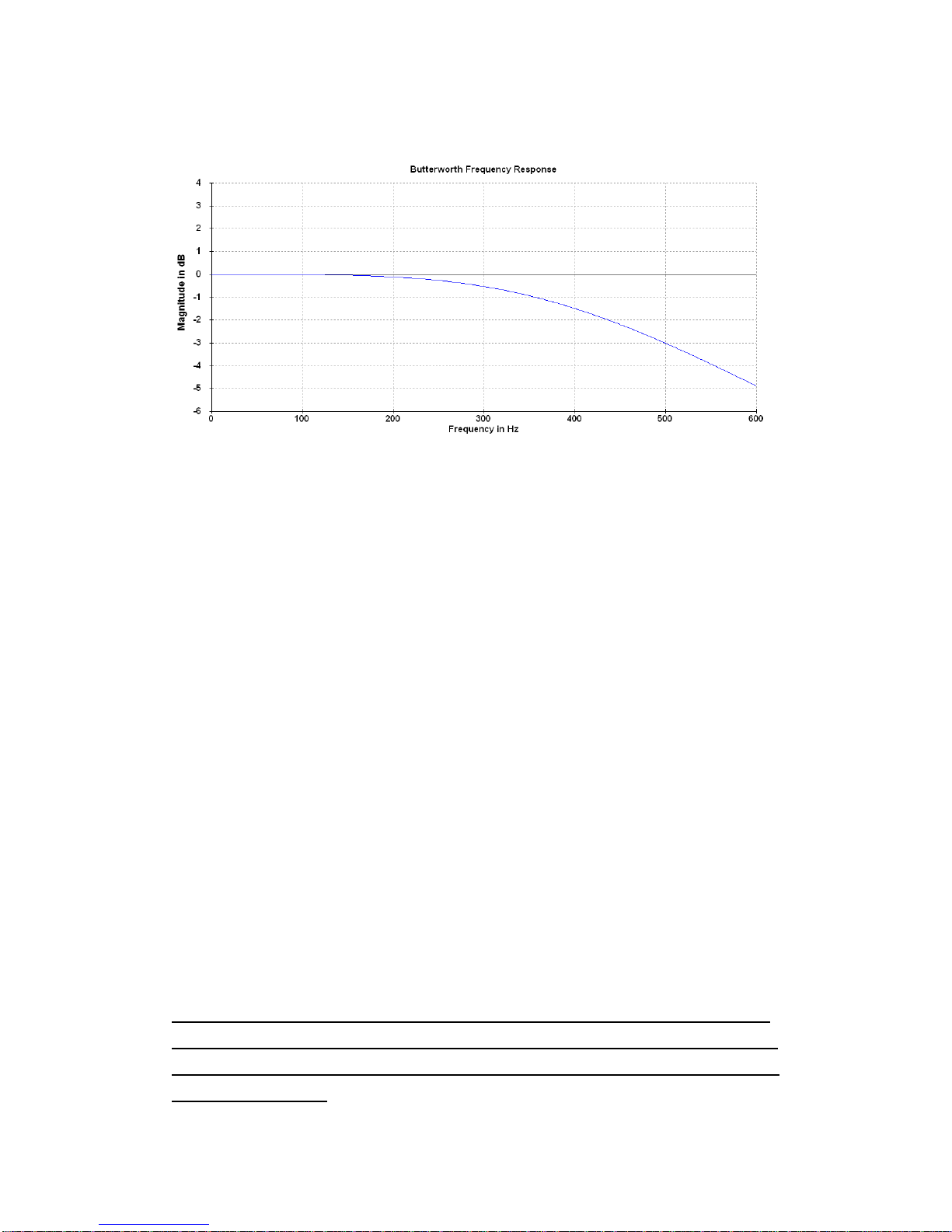
Line Filter Rules: Voltage and current features are the same; Mainly
specifications of 500Hz - 3dB shown on the Bode Plot below.
Line Filter Applications:
This function has two primary applications:
To filter and eliminate environmental noise when measuring low-frequency
small currents e.g. when measuring A/C 60Hz 100μA, without the line filter the
readings obtained are 0.000102A and 0.0001005A (nearly 100μA) with the line
filter. This function can be used to measure extremely small static
low-frequency power consumption in electrical products. This function will
affect the V/A/W readings for items with greater power consumption and a
frequency loading of over 66Hz, so please remember to switch it off.
To filter and eliminate harmonics of over 500Hzwhen conducting harmonics
analysis. It can only be used when analyzing harmonics under 500Hz (50Hz
mains power in 10 stages); please remember to switch off the line filter function
when analyzing harmonics over 500Hz.
Frequency Filter Description: When the signal to be measured has a base
frequency of 50Hz/60Hz and a high-frequency component, turn the F-Filter on
to filter out signals over 500Hz and only show those lower than 500Hz. This
function only filters some frequencies and has no affected whatsoever on
voltage/current/wattage.
The frequency filter must be switched off when the base frequency is greater
than 490Hz to avoid affecting the bandwidth of the volt frequency counter and
current frequency counter, making it impossible to measure the actual volt and
current frequencies.
Page 25
2015/7/07 Version
24
Section 4.8 Set Frequency CF Value
Keys:
Steps:
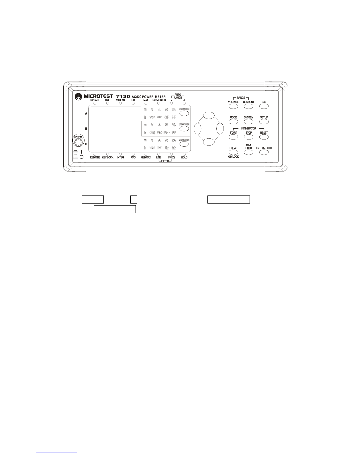
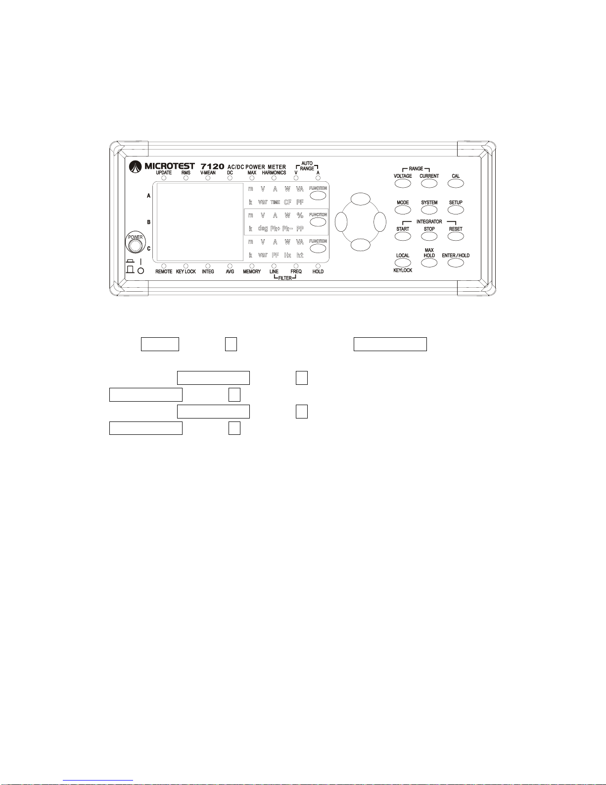
Press SETUP and use ↑↓ to select CF then press ENTER/HOLD. Select 3/9
and press ENTER/HOLD to switch between current CF3 / CF9
Description: Maximum CF3 crest current/RMS current ratio setting is 330%;
set crest current/RMS current maximum ratio to 990% to eliminate time and
precision spent switching small range when testing electrical items with high
current crest factors to maintain the integrity of the current measurement.
When settings range for CF3 current 0.3A (inc. 0.3A) or CF9 0.1A (inc. 0.1A)
the current measurement uses a 0.25 ohm shunt. The hardware will force an
automatic gear switch when the current exceeds 1.3A (AC) or 1.8A (DC) to
protect the internal shunt from combustion, and when the device is switched off
the internal default is to use the 0.0025 ohm circuit to protect the 0.25 ohm
from accidental exertion and burn-out from large currents.
CF Definitions:
Crest current / RMS gear values all based of sine waves.
Page 26
2015/7/07 Version
25
Section 4.9 Setting 4th Display Measurement Values
Keys:
Steps:
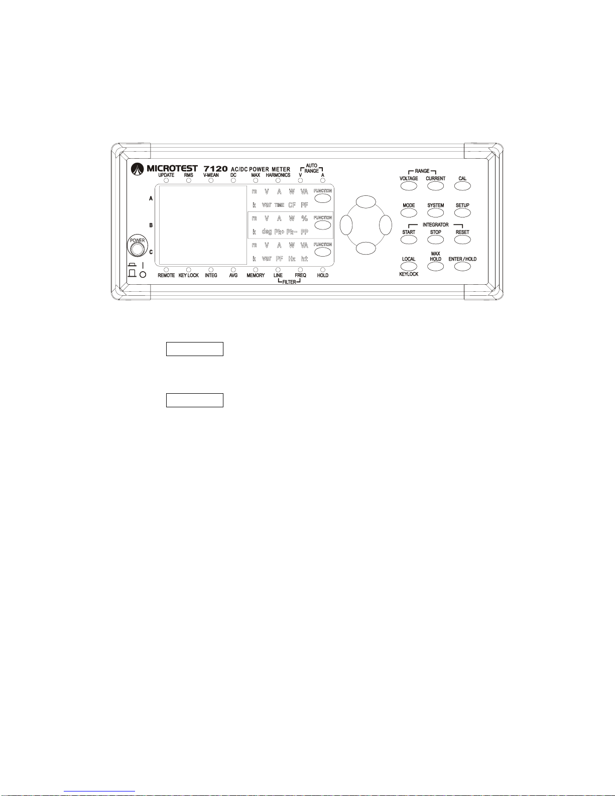
Press SETUP and use ↑↓ to select DISPL, press ENTER/HOLD and select
ON/OFF/SET.
In SET press ENTER/HOLD and use ↑↓ to select Fun2, then press
ENTER/HOLD and use ↑↓ to select display values to alternate.
In SET press ENTER/HOLD and use ↑↓ to select intvl, then press
ENTER/HOLD and use ↑↓ to select from settings 1~30 for switching display
interval time.
Description: This function allows the first display to alternately display two
measurement values.
FUNC2: Select the second measurement value to display.
In RMS mode select either V, A, W, VA, VAR, Vcf, Acf or PF.
In HARM mode select either Order, V, A, W, or PF.
INTAL: Set the interval between the alternating displays - can
choose between 1-30 seconds.
Page 27
2015/7/07 Version
26
Section 4.10 Keyboard Lock
Keys:
Steps:
Set Keyboard Lock
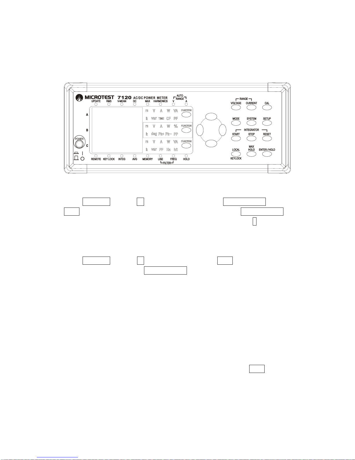
Press KEY LOCK to immediately lock the keyboard.
Unlock Keyboard
Press KEY LOCK again to immediately unlock the keyboard.
Description:
Locking the keyboard prevents all other keys from working, preventing
erroneous setting adjustments. If a locked key is pressed Display A will flash a
Lock message.
Page 28
2015/7/07 Version
27
Section 4.11 Store/Load Panel Settings Configuration
Keys:
Steps:
Store and Delete
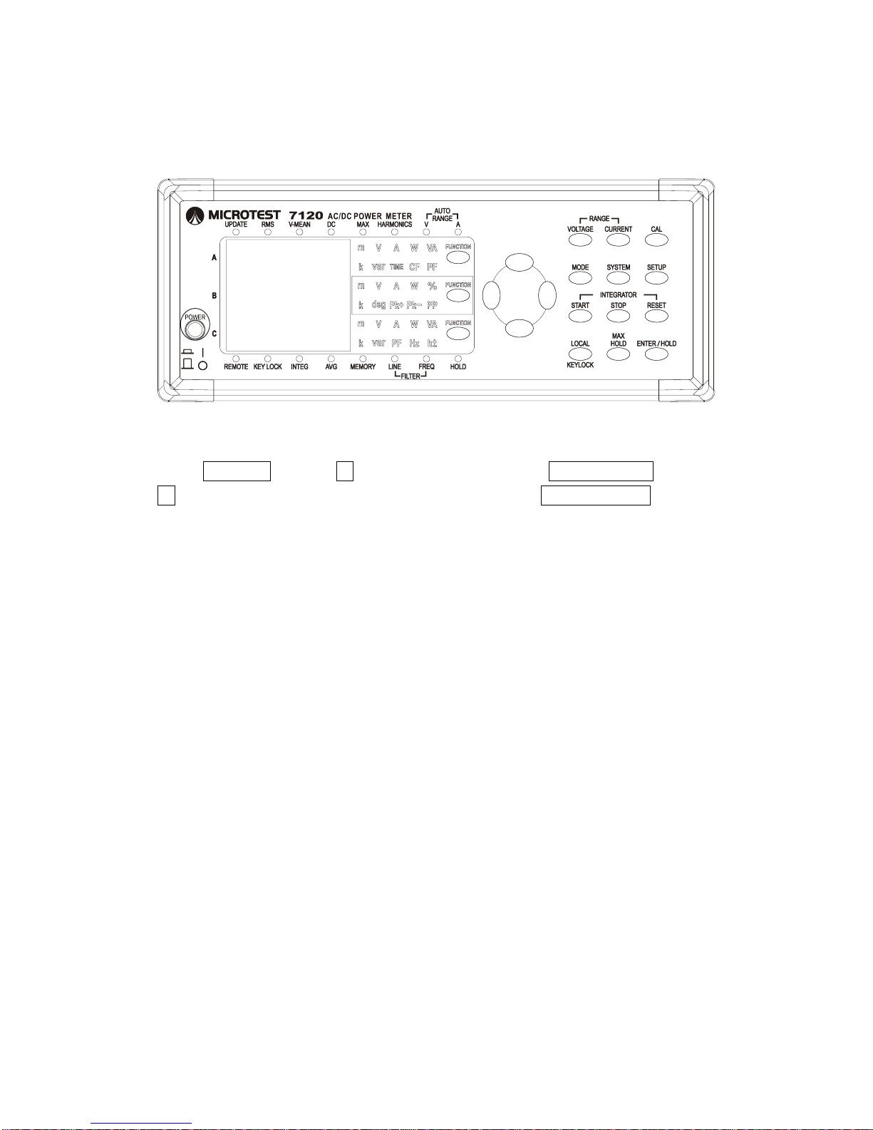
Press SYSTEM and use ↑↓ to select Store, then press ENTER/HOLD and use
← → to switch between the six storage slots, and then press ENTER/HOLD to
save. The C Display will indicate a full slot with the letter F, press ↓ to delete
the stored memory. The C display will show - to indicate an empty slot.
Load Settings
Press SYSTEM and use ↑↓ to select Recall, the use ← → to switch between
the six storage slots. Press ENTER/HOLD to immediately read the panel
settings.
Description:
There are six storage slots to save panel settings. Current device settings can
be saved. Used slots are indicated with an F on the display, and empty slots
are indicated with a single line. Factory default settings leave all six slots
empty.
STORE / RECALL: To save or load the current settings use the ← → to select
a slot. FUNC A, B, and C will display the content of the
currently selected file; press the down button to delete the
file and the ENTER button to save the current settings in
the slot/load the settings from the slot.
Page 29
2015/7/07 Version
28
Section 4.12 Set GPIB Address
Keys:
Steps:
Press SYSTEM and use ↑↓ to select GPIB, then press ENTER/HOLD and use
↑↓ to toggle between GPIB Address 1~30, then press ENTER /HOLD to finish.
Description:
This function sets the GPIB address within a range of 1-30.
Page 30
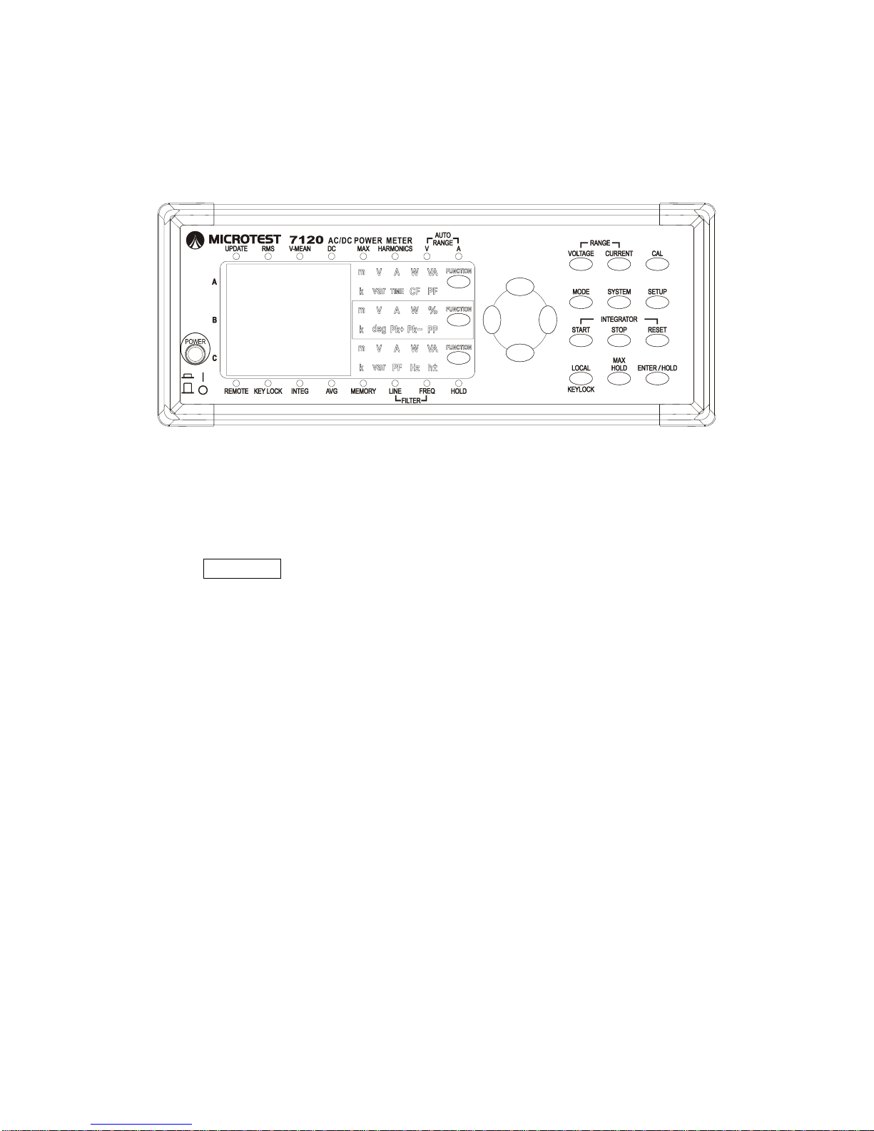
2015/7/07 Version
29
Section 4.13 Remote Control Mode
Keys:
Steps:
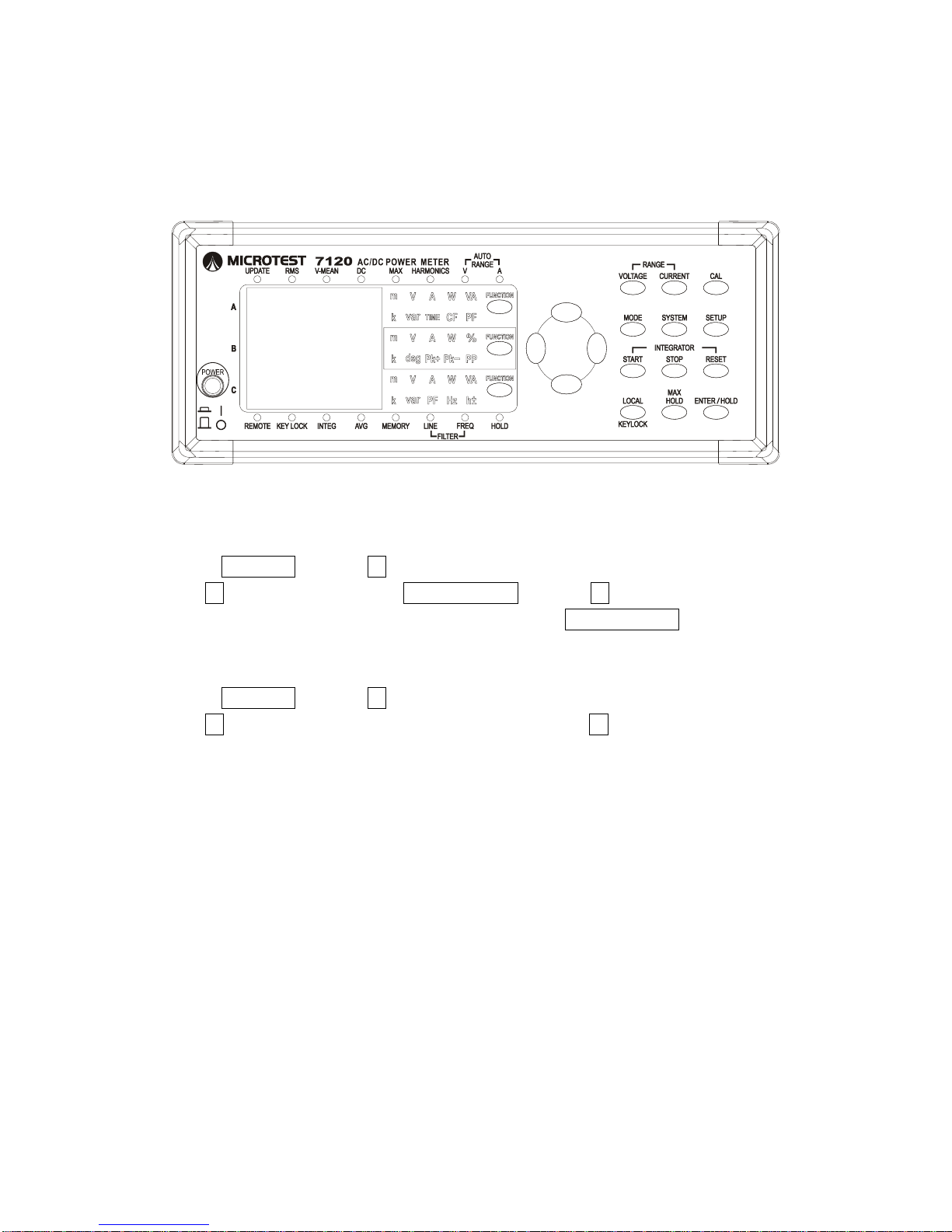
Setting a correct GPIB address or RS232 Baud rate will result in the
Remote light being lit when a PC is successfully connected.
Exit Remote Control Mode
Press KEYLOCK to immediately exit remote control mode.
Description:
Users cannot use keys to control the device when the 7120 is being controlled
remotely. Remote Control mode must be exited in order to manually control the
device. The device will automatically enter this mode upon receipt of remote
control commands.
Page 31
2015/7/07 Version
30
Section 4.14 Set RS232 Baud rate and Final Character
Keys:
Steps:
Set Baud rate
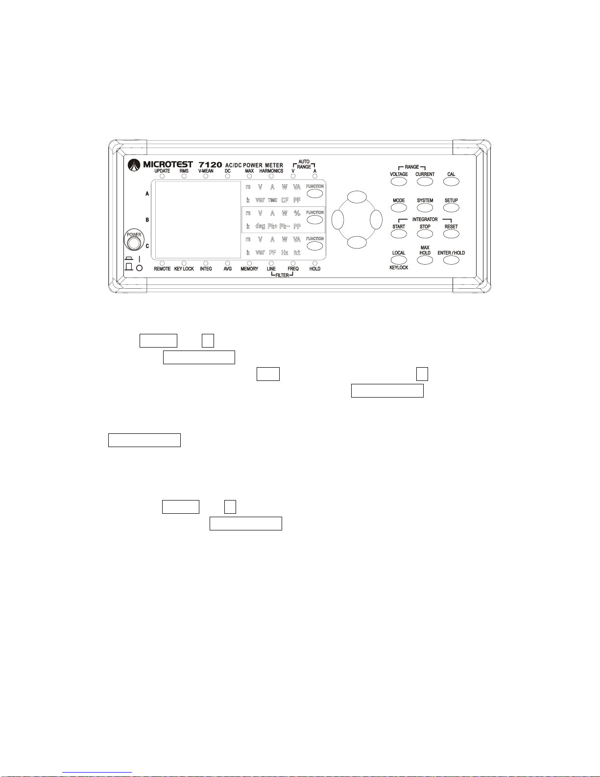
Press SYSTEM and use ↑↓ to select RE-232, then press ENTER/HOLD and
use ↑↓ to select b.rate. Press ENTER/HOLD and use ↑↓ to toggle between
9600 / 19200 / 38400 / 57600 /115200, then press ENTER/HOLD to complete
7120 Baud rate settings.
Press SYSTEM and use ↑↓ to select RE-232, then press ENTER/HOLD and
use ↑↓ to select EoL 2. Press ENTER/HOLD and use ↑↓ to select Final
Character CR(0xd) or LF(0xa).
Description:
When connecting to a PC using RS232 ensure that Baud rate settings are
correct and set data 8-bit to have a starting bit and a final character with LF as
the final character.
Page 32
2015/7/07 Version
31
Section 4.15 The SCALE Function
Keys:
Steps:
Set Scale Amplification Parameters
Press SETUP and ↑↓ select SCALE, press ENTER/HOLD and toggle to Data,
then press ENTER/HOLD to enter Amplification Settings.
A Display shows P 1.000, use ←→ to select the digits and use ↑↓ to adjust the
value by decimals. Press ENTER/HOLD once set to
enter C Settings.
B Display shows C 1.000; follow instructions for A Display then press
ENTER/HOLD once set to enter P Settings.
C Display shows F 1.000; follow instructions for B Display.
Set SCALE ON / OFF
Press SETUP and ↑↓ select SCALE, press ENTER/HOLD and toggle
ON/OFF, then press ENTER/HOLD to finish settings.
Description: This function is used with external potential transformers (P.T.),
current transformers (C.T.) or shunts to convert numerical amplifications of
measured voltage, current, power and other data. When this function is turned
on all measured values will be amplified by the set amount and directly
displayed on the screen.
Caution: When using P.T.s, C.T.s or shunts make sure that inputs into the 7120
voltage and current ports are within electrical specifications.
Page 33
2015/7/07 Version
32
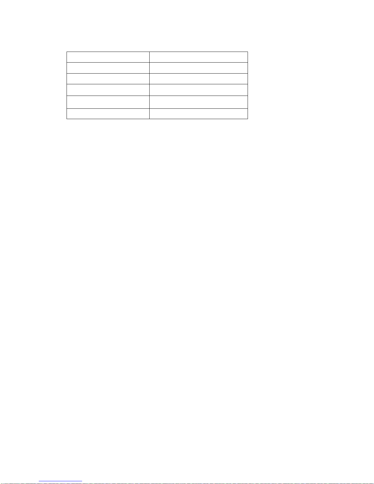
Measured Value
Converted Result
Voltage (V)
P (set scale value) * V
Current (A)
C (set scale value)* A
Active Power (W)
F (set scale value)* P * C * W
Variance (var)
F * P * C * var
Apparent Power (VA)
F * P * C * VA
Page 34
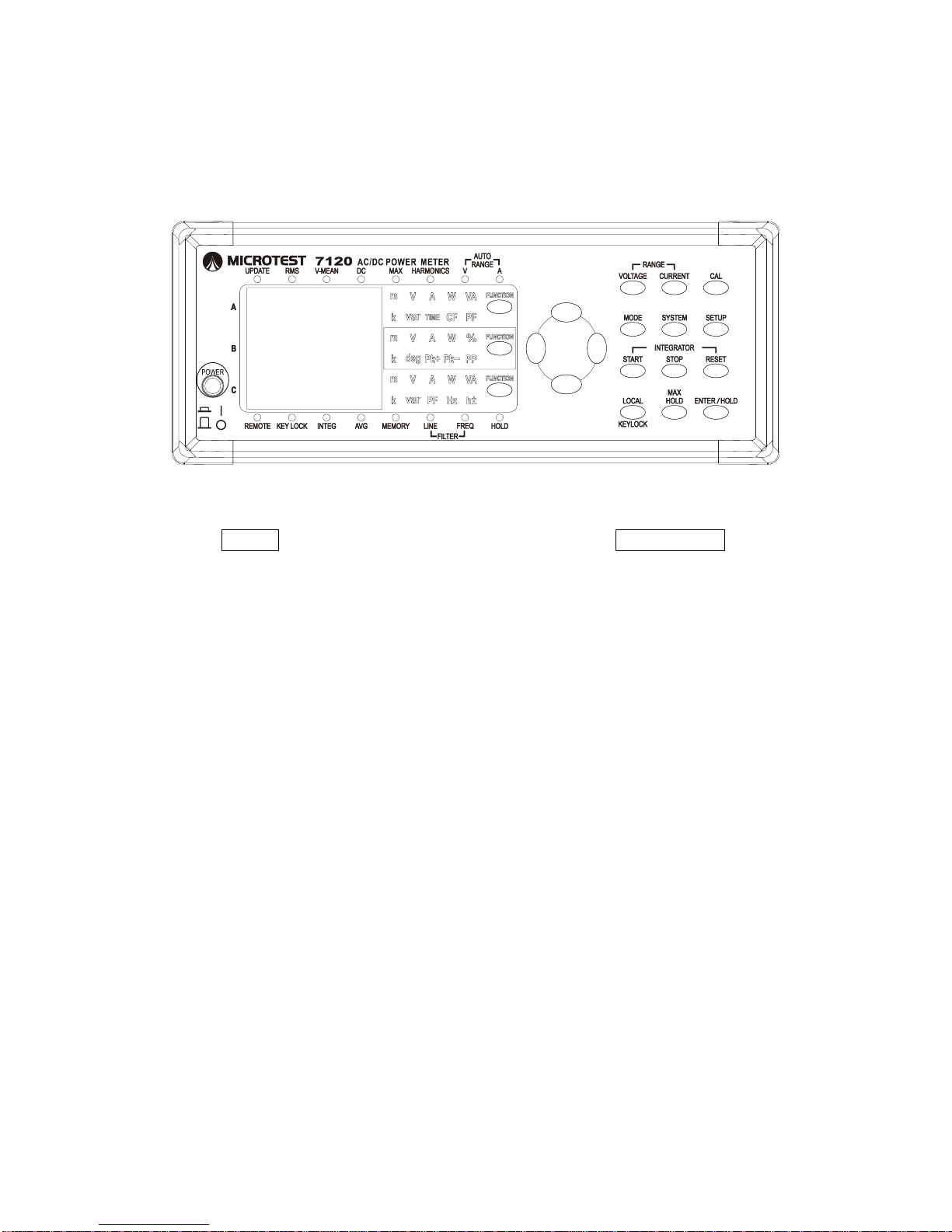
2015/7/07 Version
33
Section 4.16 Use Power Integrator
Keys:
Steps:
Press START to starting Integrator operation and use FUNCTION C to
switch The display C to show W-H± or A-H± Reading.
Description:
This function is to calculate accumulated power use. Power and current
consumption will begin to be counted until the user presses the STOP button.
Counting time is set in 00.00.00 (HH.MM.SS). Pressing the Start Accumulating
Power button when time parameters are greater than zero will turn this time
into a countdown timer and settings will return to their original parameters once
the countdown reaches zero. Pressing the Start Accumulating Power button
when time parameters are zero will cause these parameters to count the
length of accumulated time.
Page 35
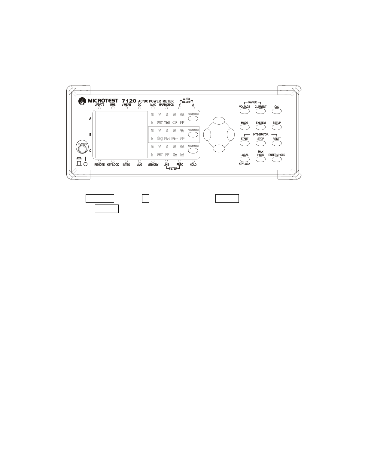
2015/7/07 Version
34
Section 4.17 Power Supply Frequency Parameters
Keys:
Steps:
Press SYSTEM and use ↑↓ select ACLINE press ENTER to select 50Hz / 60
Hz press ENTER to complete setting.
Description:
This function can measure average values for AC power supply cycles in
different regions (DC mode), increasing measurement value stability. Select
between 50Hz and 60Hz; best results are obtained when the appropriate
frequency is selected for your current power supply frequency.
Page 36
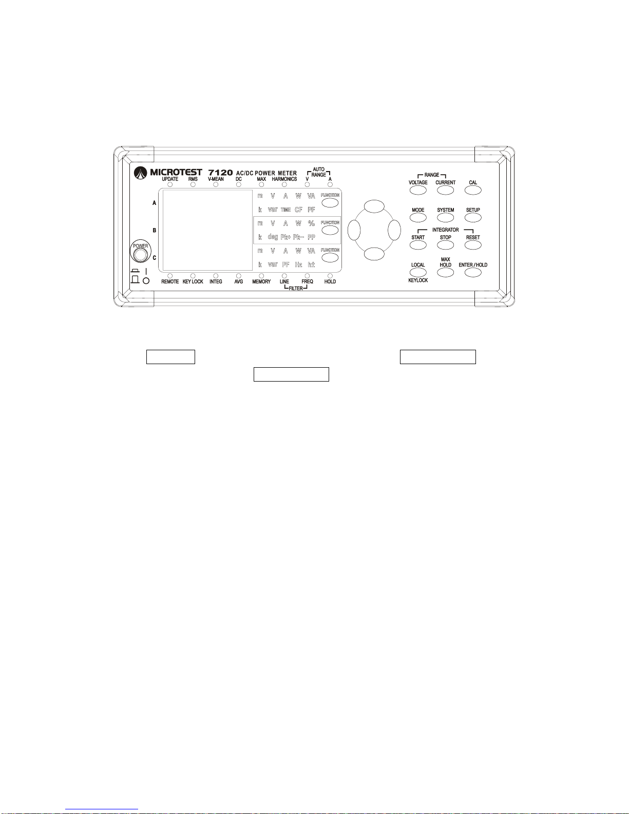
2015/7/07 Version
35
Section 4.18 Calibrate to Zero
Keys:
Steps:
Press SYSTEM and use ↑↓ to select ZERO, then press ENTER/HOLD and
use ↑↓ to select ON. Press ENTER/HOLD to start calibration to Zero.
Description:
Zero calibration is carried out in the factory to ensure the precision of the
device.
Devices are calibrated in the factory at 23°C ±1°C and RH 50%±10%. Users
are advised to recalibrate the device to zero if the environment of use exceeds
the factory environment by ±5°C in the interest of obtaining best results.
Before using this function, warm the machine up for 30 minutes and set
voltage and current to Auto range. Remove all connections from the front
and back panels and short terminals V+ and V- on the back panel before
using this function. The device will automatically carry out a zero calibration
once the command has been executed and the calibration will take
approximately 10 seconds, after which the device will re-enter measurement
mode.
Page 37
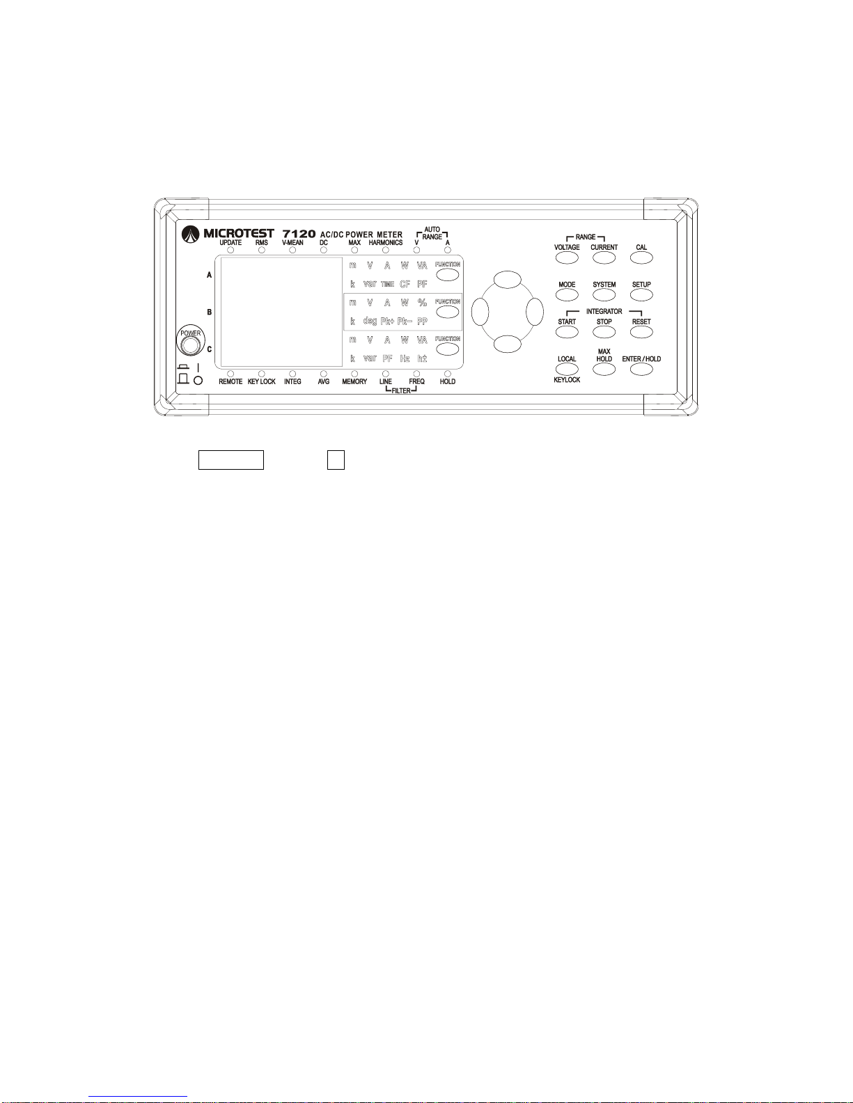
2015/7/07 Version
36
Section 4.19 Software Version Look-up
Keys:
Steps:
Press SYSTEM and use ↑↓ to select VER and check the Firmware version and
date.
Description:
The Version screen displays the current version and date of the internal device
program.
Page 38
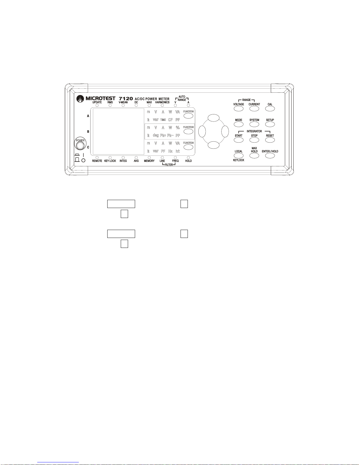
2015/7/07 Version
37
Section 4.20 Real time measure data storing
Keys:
Steps:
Save:
Open the SYSTEM menu and use ↑↓ to select MEMORY, then press
RECORD and use ↑↓ to toggle to ON and begin data recording
Time Interval Settings (controls both play and recording intervals):
Open the SYSTEM menu and use ↑↓ to select MEMORY, then press
RECORD and use ↑↓ to toggle to Intval. Press ENTER/HOLD and use ←→ to
adjust the hours/minutes/seconds using the up/down arrows. Once the desired
time has been set, press ENTER/HOLD to save your changes. If this time is
set to 00:00:00 play and recording intervals will by synchronized to the Update
rate.
Description:
The 7120 Buind-in 1,000 space of flash memory for storing measurement
data. Each unit of data records the AC/DC voltage, AC/DC current, voltage
frequency, current frequency, power, voltage plus/minus peak values, current
plus/minus peak values, voltage peak-to-peak, current peak-to-peak, power
factor, voltage/current phase angle, voltage CF, current CF, apparent power,
weakness, and total voltage harmonic distortion at the time of recording, and in
harmonics mode also records 50 stages of voltage/current/wattage capacity
and their distortion ratios.
This function is used in long-term power analyses. Range and detailed
settings are recorded together with the recorded data and displayed together
Page 39

2015/7/07 Version
38
during playback. No settings on the screen can be changed and the MEMORY
light will flash during playback. The UPDATE light will stop flashing when
playback concludes.
Page 40
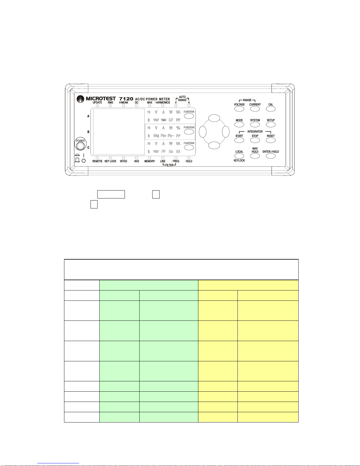
2015/7/07 Version
39
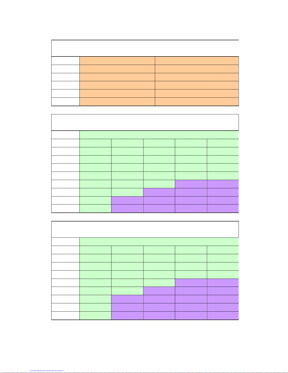
Section 4.21 Reso Settings
Keys:
Steps:
Press SYSTEM and use ↑↓ to select RESO, then press ENTER/HOLD
and use ↑↓ to select HI/LO
Description:
This function can be used to switch between value decimals on the LED
display. Detailed voltage and current display rules are outlined in the following
two tables.
Current gear display rules for when RESO = LO, are given in the below table;
add one decimal place when RESO = HI.
CF3
CF9
A
Unit
A
Unit
10mA
0.20-21.50
mA 2 decimal
places
0.60-64.50
mA 2 decimal
places
30mA
0.60-64.50
mA 2 decimal
places
2.0-215.0
mA 1 decimal place
100mA
2.0-215.0
mA 1 decimal
place
6.0-645.0
mA 1 decimal place
300mA
6.0-645.0
mA 1 decimal
place
0.060-2.150
A 3 decimal places
1A
0.020-2.150
A 3 decimal places
0.060-6.450
A 3 decimal places
3A
0.060-6.450
A 3 decimal places
0.20-20.00
A 2 decimal places
10A
0.20-20.00
A 2 decimal places
0.40-20.00
A 2 decimal places
20A
0.40-20.00
A 2 decimal places
0.40-20.00
A 2 decimal places
Page 41
2015/7/07 Version
40
Voltage gear display rules for when RESO = LO, are given in the below table;
add one decimal place when RESO = HI.
V
Unit
10V
0.10-16.00
V 2 decimal places
30V
0.30-48.00
V 2 decimal places
100V
1.0-160.0
V 1 decimal place
300V
3.0-480.0
V 1 decimal place
600V
6.0-800.0
V 1 decimal place
CF3 Wattage gear display rules for when RESO = LO, are given in the below
table; add one decimal place when RESO = HI.
CF3
10V
30V
100V
300V
600V
10mA
000.0mW
0.000W
0.000W
00.00W
00.00W
30mA
0.000W
0.000W
00.00W
00.00W
00.00W
100mA
0.000W
00.00W
00.00W
000.0W
000.0W
300mA
00.00W
00.00W
000.0W
000.0W
000.0W
1A
00.00W
000.0W
000.0W
0.000KW
0.000KW
3A
000.0W
000.0W
0.000KW
0.000KW
0.000KW
10A
000.0W
0.000KW
0.000KW
0.00KW
00.00KW
20A
000.0W
0.000KW
0.000KW
0.00KW
00.00KW
CF9 Wattage gear display rules for when RESO = LO, are given in the below
table; add one decimal place when RESO = HI.
CF9
10V
30V
100V
300V
600V
10mA
0.000W
0.000W
00.00W
00.00W
00.00W
30mA
0.000W
00.00W
00.00W
000.0W
000.0W
100mA
00.00W
00.00W
000.0W
000.0W
000.0W
300mA
00.00W
000.0W
000.0W
0.000KW
0.000KW
1A
000.0W
000.0W
0.000KW
0.000KW
0.000KW
3A
000.0W
0.000KW
0.000KW
00.00KW
00.00KW
10A
000.0W
0.000KW
0.000KW
00.00KW
00.00KW
20A
000.0W
0.000KW
0.000KW
00.00KW
00.00KW
Page 42
2015/7/07 Version
41
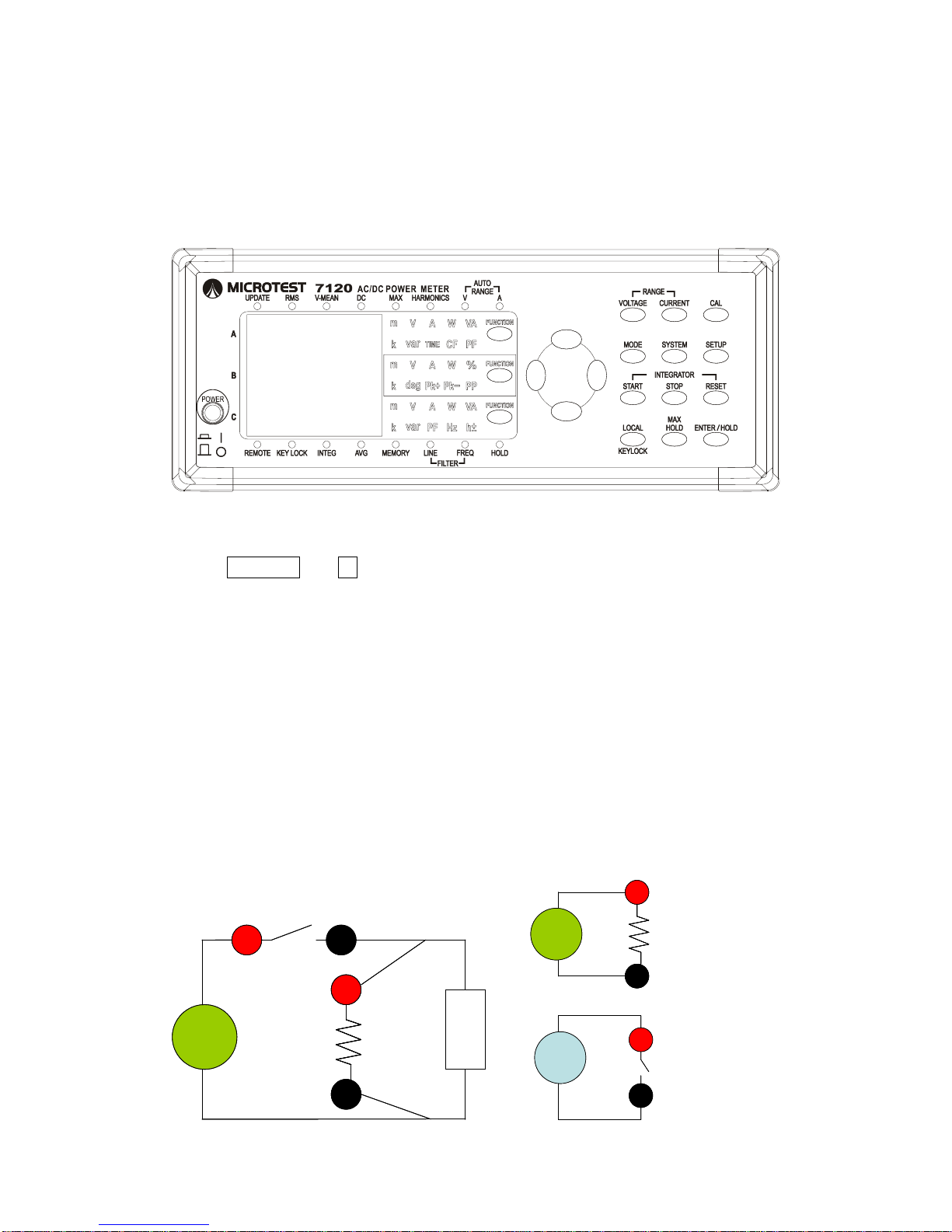
Section 4.22 Gauge Head Power Consumption
Deductions
Keys:
Steps:
In SYSTEM use ↑↓ to select M_CMP and then select ON or OFF
Description:
This function deducts internal micro-consumption from the voltmeter. E.G.
220V AC 60Hz with a F71201 Test Box using voltage set to I will measure a
wattage of 0.048W (gauge head consumption). With MCP ON a deduction of
VRMS2 / 1M will be made for the voltmeter internal resister and the panel
reading will show a consumption of almost 0W. When connected to an external
Calibrator this function set M_CMP to OFF, as the voltage and current of the
calibrator are independent. This function should also be off if the voltmeter is
bridged in before the ammeter.
快速接頭量測接線
V
Source
I+ I-
負載
1MΩ
V+
V-
Breaker
快速接頭量測接線
V
Source
I+ I-
負載
1MΩ
V+V-V+
V-
Breaker
1MΩ
V
Source
I+
獨力電壓錶接線
V+
V-
A
Source
I-
獨力電流錶接線
1MΩ
V
Source
I+
獨力電壓錶接線
V+V-V+
V-
A
Source
I-
獨力電流錶接線
Fast Connection Measuring Wiring
Independent Voltmeter Wiring
Independent Ammeter Wiring
Load
Page 43
2015/7/07 Version
42
Chapter 5 Display Measurement
Values
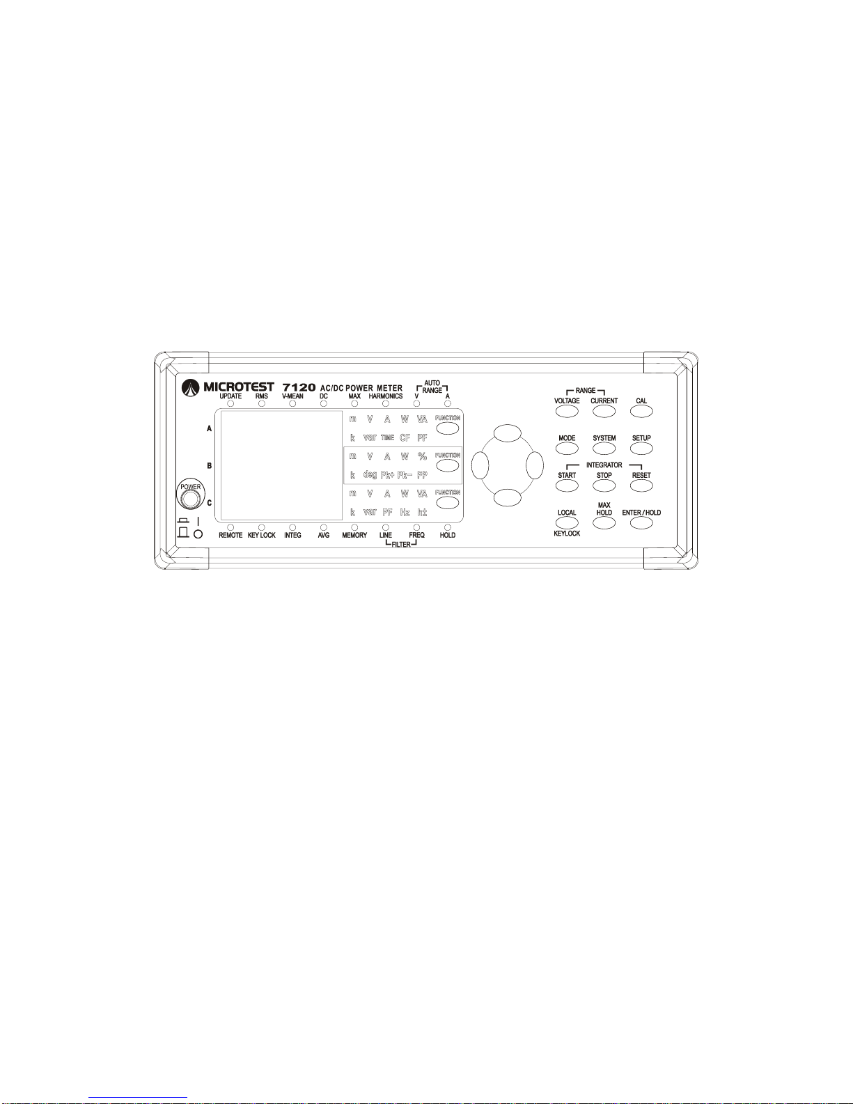
Section 5.1 Panel Description
Indicator LEDs are used in the panel description to indicate the current settings
and measurement functions - e.g. Rms indicates that the device is currently set
to measure RMS.
[1] Status Lights:
1. UPATE: indicates sampling (flash speed is the update rate).
2. RMS: Measure AC mode.
3. VOLT MEAN: Measure average voltage mode.
4. MAX HOLD: Maintain maximum value function.
5. HARMONICS: Measure harmonics mode.
6. V AUTO RANGE: Voltage range are automatically set.
7. A AUTO RANGE: Current range are automatically set.
8. REMOTE: Remote control mode
9. KEY LOCK: keyboard is locked.
10. INTEG: Power Accumulation Mode.
11. AVG: Set average value function activated.
12. MEMORY: Data recording/playback indicator light (flashes with
UPDATE light when saving).
13. L-FILTER: Line filter function activated.
14. F-FILTER: Frequency filter function activated.
15. HOLD: Panel data update temporarily on hold.
Page 44
2015/7/07 Version
43
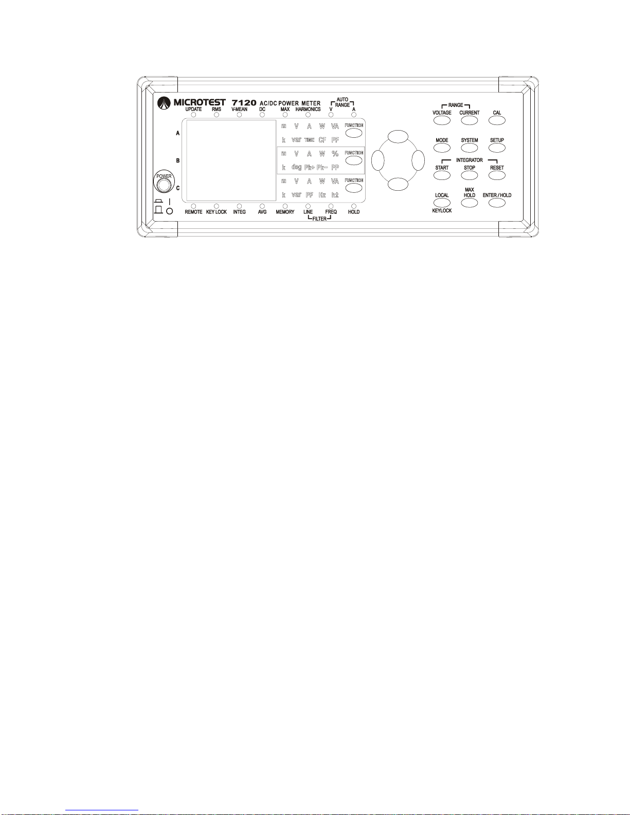
[2]. POWER: Power Supply: Press I to switch on and O to switch off.
[3]. DISPLAY_A Measurement Value Display Area.
[4]. DISPLAY_A Measurement Item Display Area.
V: Displays voltage.
A: Displays amperage.
W: Displays wattage.
VA: Displays Apparent Power.
var: Displays Variance.
ET: Displays accumulated time.
V_CF: Displays voltage waveform factor.
A_CF: Displays current waveform factor.
PF: Displays power factor.
[5]. DISPLAY_B Measurement Value Display Area.
[6]. DISPLAY_B Measurement Item Display Area.
V: Displays voltage.
A: Displays amperage.
W: Displays wattage.
V_%: Displays voltage harmonic distortion (7-segment display t = 50
stage total harmonic distortion).
A_%: Displays current harmonic distortion (7- segment display t = 50
stage total harmonic distortion).
W_%: Displays Power/Harmonic Distortion
Deg: Displays phase angle.
V-Deg In Harmonics mode, displays 1-50 stages of voltage phase
angles V-Deg Definition: First stage is phase difference
between voltage and current, stages 2-50 are phase difference
between stage one voltage and stage 2-50 voltage.
Page 45

2015/7/07 Version
44
A-Deg In Harmonics mode, displays voltage phase angle A-Deg
Definition: First stage is phase difference between voltage and
current, stages 2-50 are phase difference between stage one
current and stage 2-50 current.
V_PK+: Displays voltage positive peak.
A_PK+: Displays current positive peak.
V_PK-: Displays voltage negative peak.
A_PK-: Displays current negative peak.
V_PP: Displays voltage peak-to-peak.
A_PP: Displays current peak-to-peak.
[7]. DISPLAY_C Measurement Value Display Area.
[8]. DISPLAY_C Measurement Item Display Area.
V: Displays voltage.
A: Displays amperage.
W: Displays wattage.
VA: Displays Apparent Power.
var: Displays Variance.
PF: Displays power factor.
V_Hz: Displays voltage frequency.
A_H: Displays ampere/hour.
W_H: Displays wattage/hour.
VA_H: Displays Apparent Power/hour.
var_H: Displays variance/hour.
Vpk: Displays peak voltage. Display light V lights up, a P is shown
at the left-most side of the display area.
Apk: Displays current voltage. Display light A lights up, a P is shown
at the left-most side of the display area.
[9]. Window Display Item Settings Key:
FuncA: Set DISPLAY_A display items.
FuncB: Set DISPLAY_B display items.
FuncC: Set DISPLAY_C display items.
Page 46
2015/7/07 Version
45
[10]
[11] [12]
[15]
[16]
[13]
[18] [19][17]
[14]
[10]
[11] [12]
[15]
[16]
[13]
[18] [19][17]
[14]
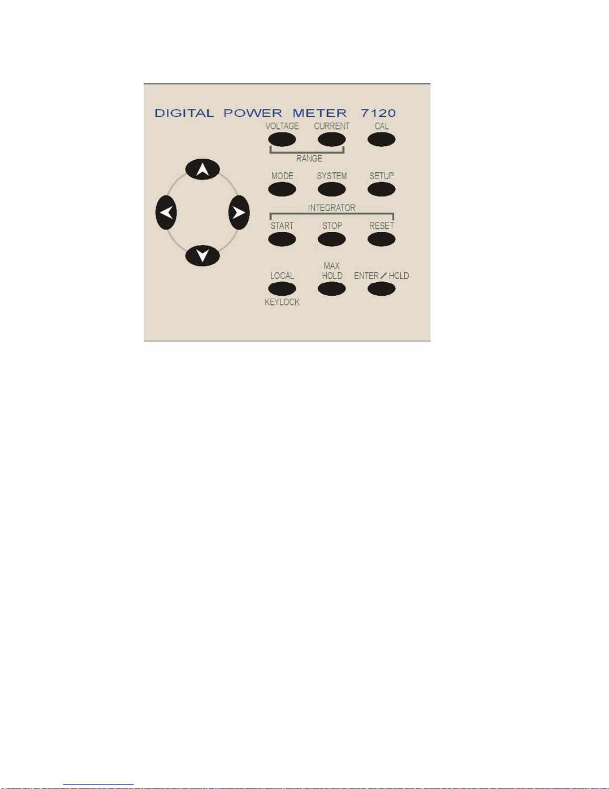
[10]. Up, down, left, right settings operating key.
[11]. Gear settings shortcut key.
[12]. Calibrate keys.
[13]. Measurement mode selection key.
[14]. System function settings key.
[15]. Gear, average value, update rate settings key.
[16]. Accumulated settings key:
Start/Stop: Start or stop accumulation.
Reset: Press this button to clear all accumulated values (AH, WH,
VAH, varH).
[17]. Unlock keyboard/remote control mode settings key.
[18]. MAX.HOLD mode shortcut key: Turn on this mode to only retain
maximum values, press again to return to normal measuring mode.
[19]. Input/Hold Key: During settings mode this key is an input key; in
measurement mode, this key retains data and pressing this key will hold
all currently measured data and prevent updates from occurring. The
window display settings key can also be pressed to switch between item
values to display.
[20]. Device power supply socket.
[21]. Testing item object input.
Page 47

2015/7/07 Version
46
[22]. GPIB Interface socket.
[23]. RS-232 interface socket.
Section 5.2 Measurement Items:
V: Displays voltage.
A: Displays amperage.
W: Displays wattage.
VA: Displays Apparent Power.
var: Displays Variance (inactive power).
TIME: Displays accumulated time.
Pk+: Displays positive peak.
Pk-: Displays negative peak.
PP: Displays peak-to-peak.
CF: Displays waveform factor.
PF: Displays power factor.
Hz: A-HZ and VHZ display function.
Deg: Displays phase angle.
h: Displays power/hour.
%: Displays total harmonic distortion (THD).
Vpk: Displays peak voltage.
Apk: Displays current voltage.
Page 48
2015/7/07 Version
47
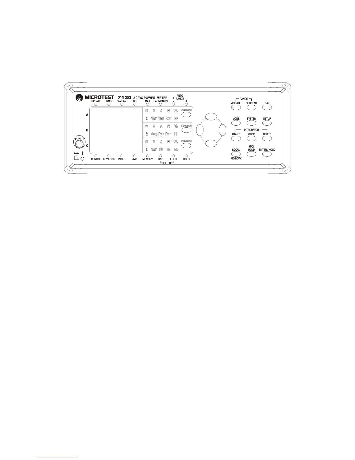
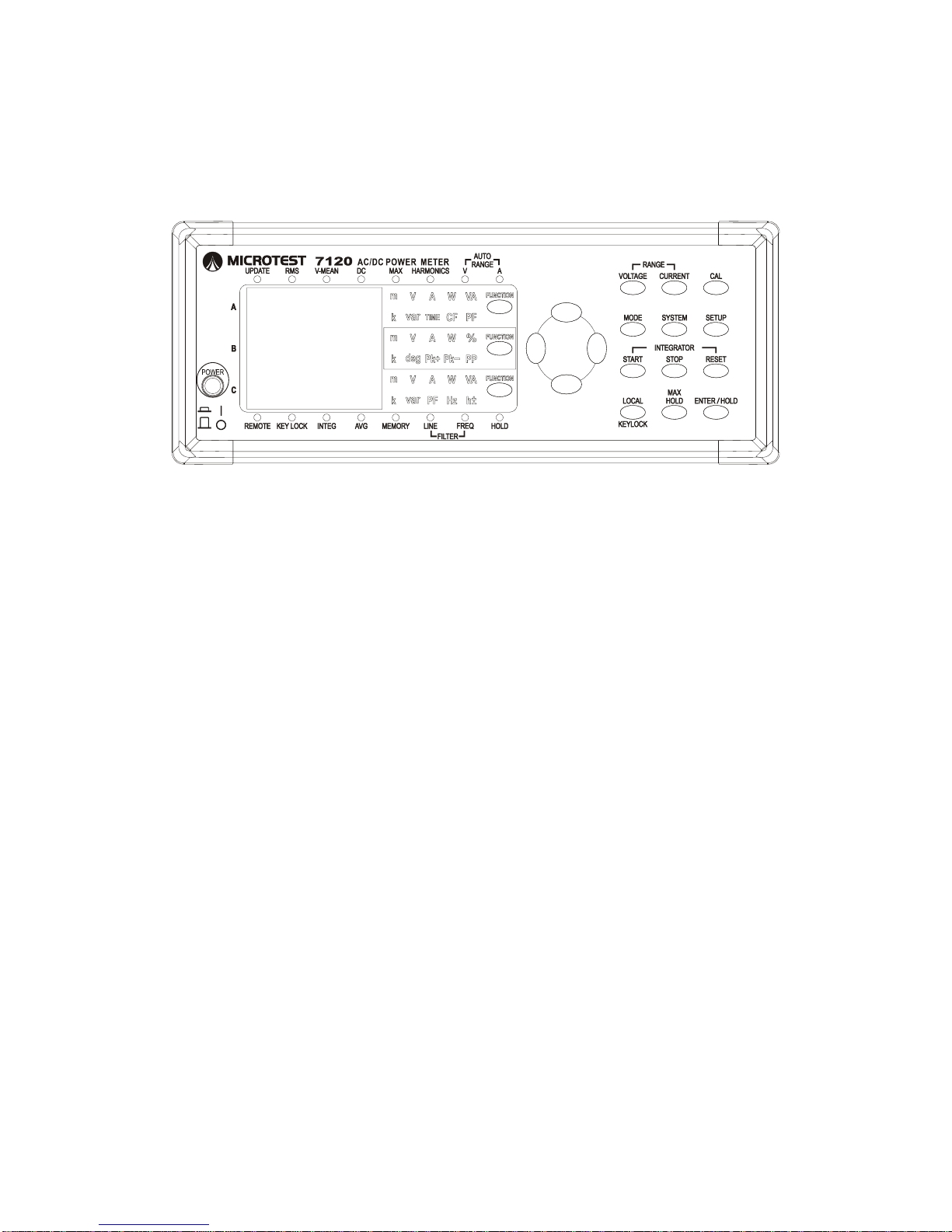
Section 5.3 Display A Measurement Display Area
Keys and Display Lights:
Description:
1. In Rms and Volt Mean modes press FunctionA key - the toggle order of
functions in Window A is below.
V A W VA var TIME V_CF A_CF PF V (Default)
2. In Harmonic mode press FunctionA key - the toggle order of functions in
Window A is below.
V A W or. Number (Default)
3. m & k are unit scientific notation lights; m = 10-3 and k = 10+3.
Page 49
2015/7/07 Version
48
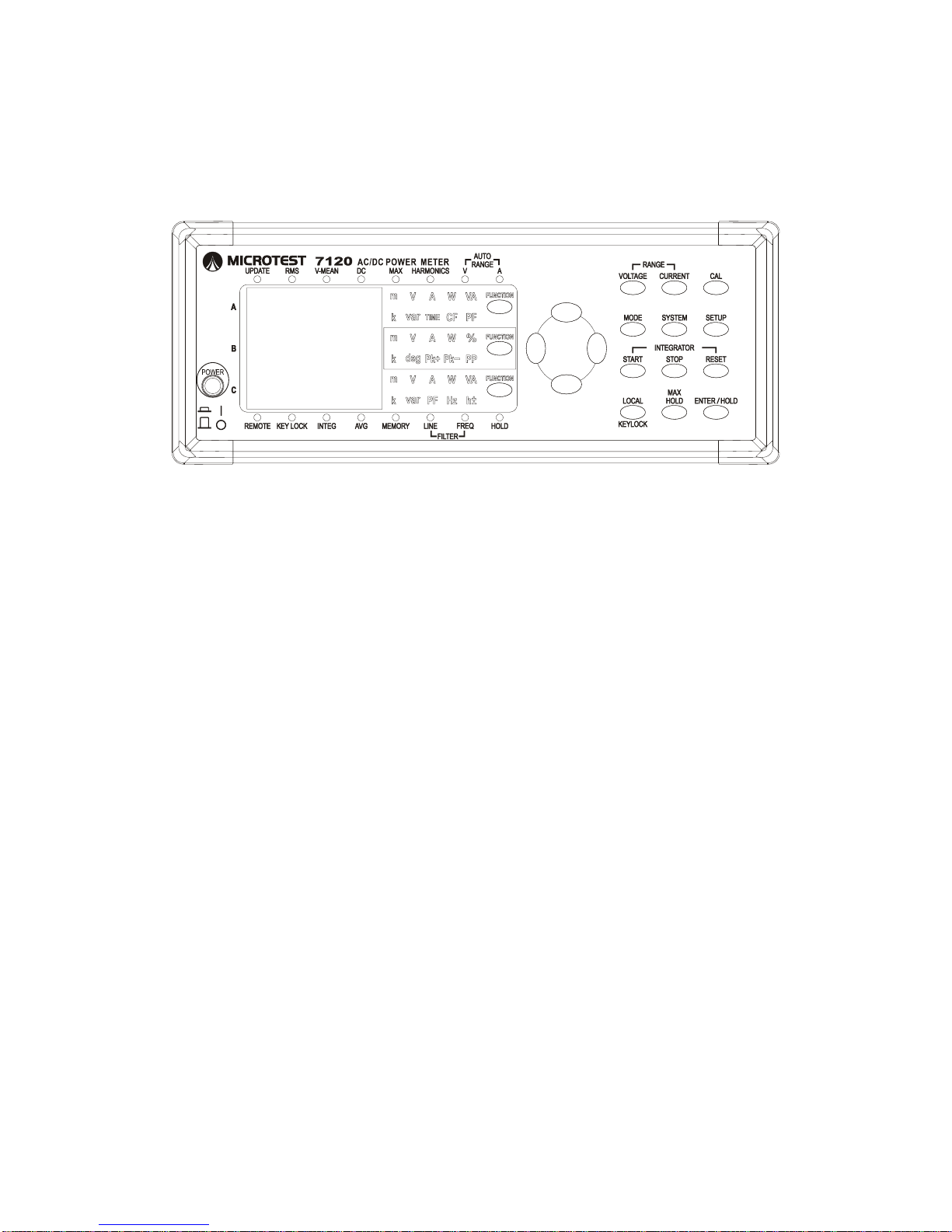
Section 5.4 Display B Measurement Display Area
Keys and Display Lights:
Description:
1. In Rms, Volt Mean and DC modes press FunctionB key - the toggle order
of functions in Window B is below.
A W Deg V_Pk+ A_Pk- V_Pk+ A_Pk- V_PP A_PP
V A(Default)
2. In Harmonic mode press FunctionB key - the toggle order of functions in
Window B is below.
V-t (default)% A-t% W% V-deg A-deg V A W V-t
(default)%,
t = total mode, in this mode pressing the left and right keys allows you to
toggle between total mode (t) and single-stage mode.
3. m & k are unit scientific notation lights; m = 10-3 and k = 10+3.
Page 50
2015/7/07 Version
49
Section 5.5 Display C Measurement Display Area
Keys and Display Lights:
Description:
1. In Rms, Volt Mean and DC modes press FuncC key - the toggle order of
functions in Window C is below.
W VA var PF Hz A_H W_H VA_H var_H
VpkApk V A W (Default)
2. In Harmonic mode press FuncC key - the toggle order of functions in
Window C is below.
VHz AHz V A W VHz (Default)
3. m & k are unit scientific notation lights; m = 10 -3 and k = 10 +3.
Note:
Vpk: Displays peak voltage. Display light V lights up, a P is shown at the
left-most side of the display area.
Apk: Displays peak voltage. Display light A lights up, a P is shown at the
left-most side of the display area.
Page 51
2015/7/07 Version
50
Chapter 6 Electrical Features
Specifications
Basic measurement mode specifications
Measurement
Foundation
Obtain a stable base frequency (less than 1% variation)
from voltage or current (non-variable) and begin taking
measurements.
Frequency
Range
15HZ ~ 100KHz
Data Length
dual 4096x16 RAM for voltage & current
ADC Data
Format
16 bits
Sampling Rate
Max 200KSPS/Basic 100KSPS/120KSPS (50Hz/60Hz)
Operation
Precision
IEEE-754 32bits
Frequency Filter
500HZ cut off, 25MHZ digital chip filter
Line Filter
500Hz -3db, Butterworth digital filter
Filter Sampling
Method
Voltage/Current 25MHZ base frequency digital dynamic
counter chip
Phase Leader
Detection
Based off the current, analog/digital mixed sensing (margin
of error within 5 degrees)
Zero Level Specifications (CF3)
Voltage
Current
AC(Noise)
DC(Offset)
AC(Noise)
DC(Offset)
10V
<0.045V
±0.01V
0.01A
<0.00005A
±0.00003A
30V
<0.045V
±0.03V
0.03A
<0.00007
±0.00003A
100V
<0.1V
±0.1V
0.1A
<0.0002A
±0.00004A
300V
<0.3V
±0.3V
0.3A
<0.0002A
±0.0003A
600V
<0.6V
±0.6V
1A
<0.008A
±0.003A
3A
<0.008A
±0.005A
10A
<0.02A
±0.01A
20A
<0.02A
±0.02A
Accessory Specification Conditions:
a. Environmental temperature variance 30 minutes after switching the
device on is within 5 degrees of 23°C.
b. Voltage offset to short circuit V+ V- with a 5cm short wire.
c. Current offset obtained with I+ I- idle contact.
d. AC Voltage/AC Current obtained with L-Filter on.
Page 52
2015/7/07 Version
51
CAT II level specifications (50H, 60Hz)
Voltage
(Red)
Voltage
(Black)
Current
(Red)
Current
(Black)
Case –
Earthed
Voltage
(Red)
---
800V RMS
600V RMS
600V RMS
600V RMS
Voltage
(Black)
800V RMS
---
600V RMS
600V RMS
600V RMS
Current
(Red)
600V RMS
600V RMS
--- 600V RMS
Current
(Black)
600V RMS
600V RMS
---
600V RMS
Case Earthed
600V RMS
600V RMS
600V RMS
600V RMS
---
Page 53
2015/7/07 Version
52
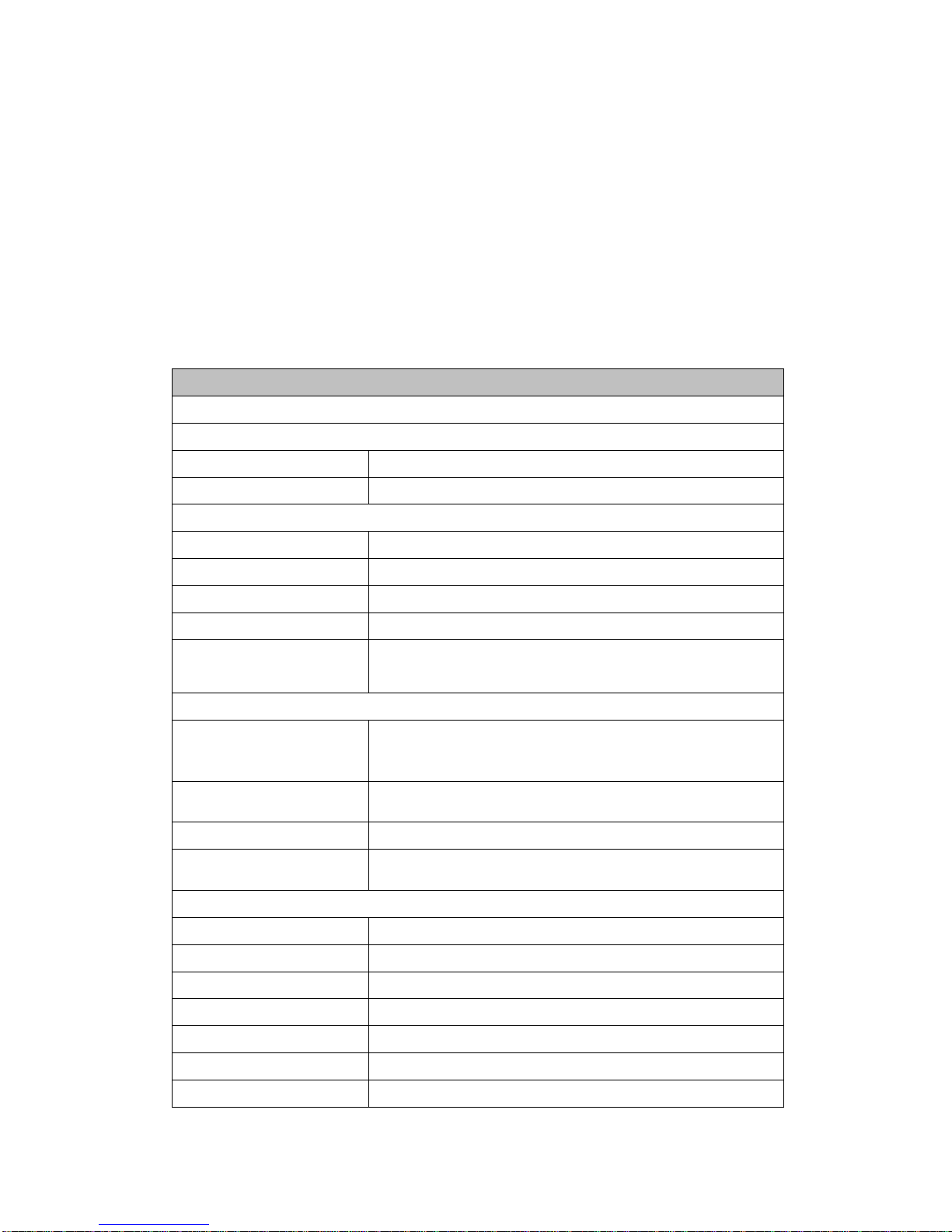
Environment of Use Requirements:
Electrical Item Specifications Scope of Warranty Temperature Within
Scope: 23±5°C
Humidity: 30 to 75%RH.
Power Factor: 1
Input signal: sine wave
With scaling off
Only use indoors after a 30 minute warm-up
New devices un-package must be zero calibration before initial use.
Calibration with a Fluke 5522A guarantees precision for 6 months.
Voltage (V)
Ranges (Auto or Manual) (5 ranges)
10V, 30V, 100V, 300V, 600V
Operating Principle
True RMS or mean value rectification
Frequency Range
DC and 15Hz to 100KHz
AC Accuracy (23°C±5°C Environmental)
15 Hz≦f<45 Hz
±(0.1% of reading + 0.4% of range)
45 Hz≦f≦66 Hz
±(0.1% of reading + 0.1 % of range)
66 Hz<f≦1 kHz
±(0.1% of reading + 0.2 % of range)
1 kHz<f≦10 kHz
±(0.07*f % of reading + 0.3 % of range) f Unit K
10 kHz<f≦100 kHz
±(0.5 % of reading + 0.5 % of range)
±[{0.04×(f–10)}% of reading]
Accessory Margin of Error Tolerance Conditions
Line Filter Tolerance:
Frequencies between 45 to 66 Hz: Add 0.2% of
reading.
Frequencies less than 45 Hz: Add 0.5% of reading
Temperature Tolerance
Effect:
Add ±0.03% of reading/°C in the range 5 to 18°C or
28°C to 40°C
Margin of Error within
12 Months:
Add ±(0.5% of reading)
DC Accuracy (23°C±5°C Environmental)
10V
{±0.2% reading ± 0.2% of range}
30V
{±0.2% reading ± 0.2% of range}
100V
{±0.2% reading ± 0.2% of range}
300V
{±0.2% reading ± 0.2% of range}
600V
{±0.2% reading ± 0.2% of range}
Maximum Input
800V RMS/1000Vpk
Input impedance
1M ohm on all ranges
Page 54
2015/7/07 Version
53
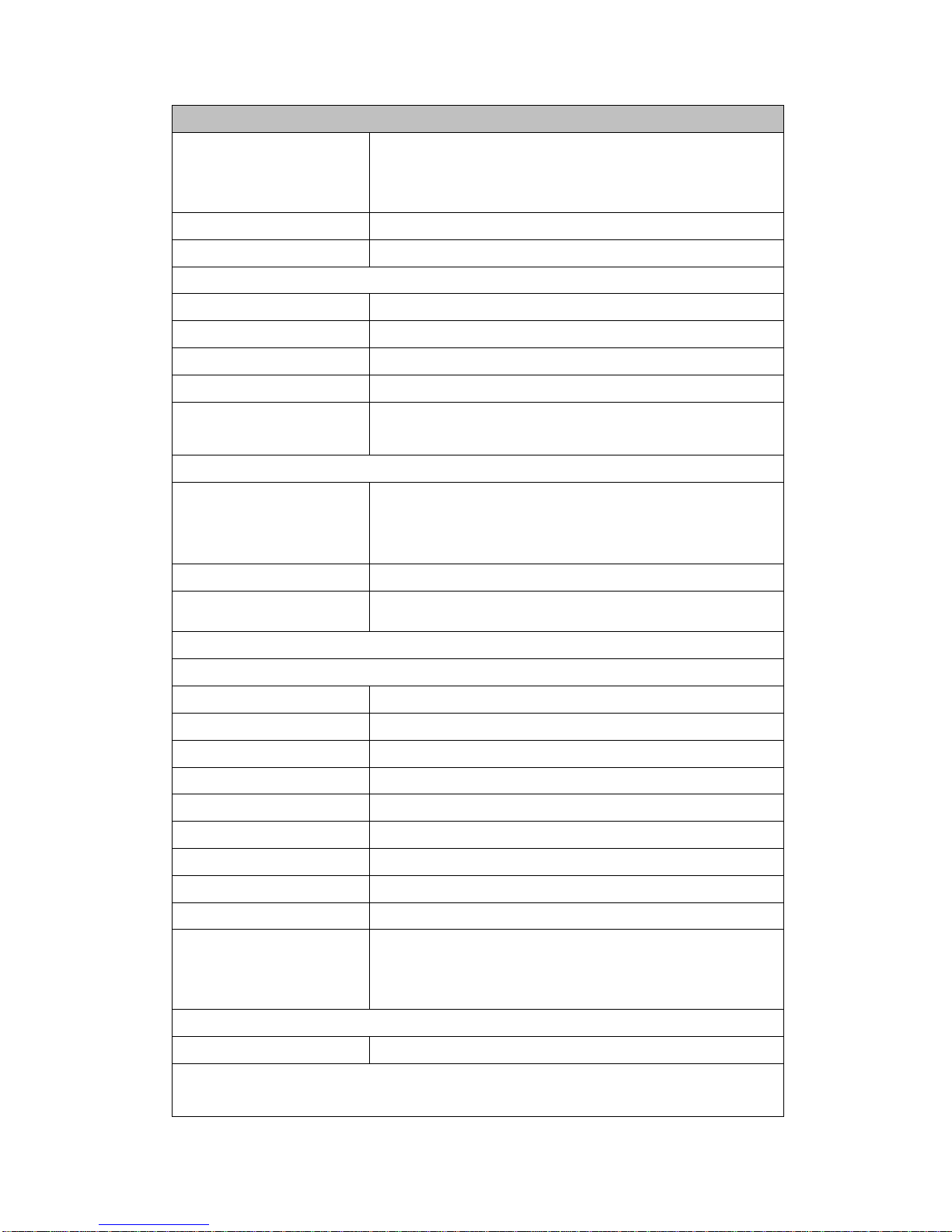
Current (A)
Ranges (Auto or
Manual)
(8 ranges)
0.01A, 0.03A, 0.1A, 0.3A, 1A, 3A, 10A, 20A
Operating Principle
True RMS or mean value rectification
Frequency Range
DC and 15Hz to 100KHz
AC Accuracy (23°C±5°C Environmental)
15 Hz≦f<45 Hz
±(0.1% of reading + 0.4% of range)
45 Hz≦f≦66 Hz
±(0.1% of reading + 0.1 % of range)
66 Hz<f≦1 kHz
±(0.1% of reading + 0.2 % of range)
1 kHz<f≦10 kHz
±((0.07 × f)% of reading + 0.3 % of range)
10 kHz<f≦100 kHz
±(0.5 % of reading + 0.5% of range)
±[{0.04×(f–10)}% of reading]
AC Accessory Margin of Error Tolerance Conditions
Line Filter Tolerance:
Frequencies between 45 to 66 Hz: Add ± 0.2% of
reading.
Frequencies less than 45 Hz: Add ± 0.5% of
reading
CF 9 Margin of Error
Add ± 0.3% of range
Temperature Effects
(AC)
Add ±0.03% of reading/°C in the range 5 to 18°C or
28°C to 40°C
DC Accuracy (23°C±5°C Environmental)
0.01A
±{(0.2)% of reading + 0.5 % of range}
0.03A
±{(0.2)% of reading + 0.5 % of range}
0.1A
±{(0.2)% of reading + 0.5 % of range}
0.3A
±{(0.2)% of reading + 0.5 % of range}
1.0A
±{(0.2)% of reading + 0.5 % of range}
3A
±{(0.2)% of reading + 0.5 % of range}
10A
±{(0.2)% of reading + 0.5 % of range}
20A
±{(0.2)% of reading + 0.5 % of range}
Input impedance
0.0025 ohm For 1A ~ 20A Range(CF3)
0.25 ohm For 0.01A~0.3A(CF3)
+10m ohm(wire) on all ranges
DC Accessory Margin of Error Tolerance Conditions
Error within 12 Months:
Add ±(0.5% of reading)
* Caution: While measuring keep the device in a well-ventilated area. For
best results never use in a closed environment.
Page 55
2015/7/07 Version
54
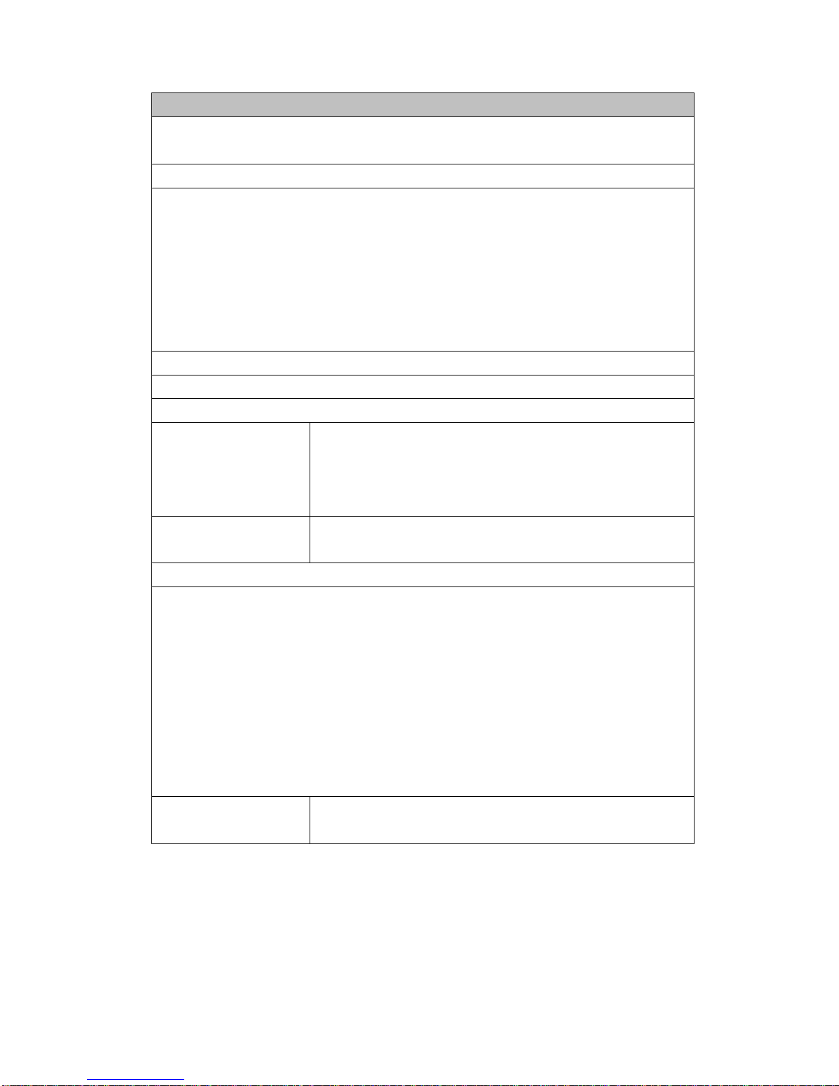
Power (W)
AC power ranges (Auto or Manual)(40 ranges) range up to 16KW
Max Power (W) value determined by max voltage gear.
AC Accuracy
15 Hz≦f<45 Hz ±(0.3% of reading + 0.2% of range)
45 Hz≦f≦66 Hz ±(0.1% of reading + 0.1 % of range)
66 Hz<f≦1 kHz ±(0.2% of reading + 0.2 % of range)
1 kHz<f≦10 kHz ±(0.4% of reading + 0.3 % of range)± [{0.06×(f)}% of
reading]
10 kHz<f≦100 kHz ±(0.5 % of reading + 0.5 % of range)±[{0.09×(f–10)}% of
reading]
Environmental Temperature (23°C±5°C)
DC ±0.2% reading ± 0.5% of range
Accessory Margin of Error Tolerance Conditions
Line Filter Margin of
Error (AC)
Frequencies between 45 to 66 Hz: Add 0.3% of
reading.
Frequencies less than 45 to 66 Hz: outside of range,
add 1% of reading
CF9 Margin of Error
(DC)
Add range tolerance * 3
Phase Margin of Error may affect power precision.
When power factor (PF) = 0, Watt margin of error range is:
Situation 1: for 45 Hz<f<66 Hz. Add ± 1.0% of VA
Situation 2: for 45 Hz>f or f >66 Hz.
Add ±{(3.5 + 0.5 × f)% of VA} for up to 100 kHz as reference data.
The unit for frequency f is kHz.
When Power Factor 0 < PF ≦ Margin of Error Range.
When 0<PF≦1 (θ: phase angle of the voltage and current)
for 45 Hz≦f≦66 Hz. Add ± power reading *{tan(θ)*(0.5)}%
for f < 45 Hz, f >66 Hz. Add ± power reading *{ tan θ* (0.5×f+0.2) }%
Margin of Error
within 12 Months:
Add ±(0.5% of reading)
Page 56
2015/7/07 Version
55
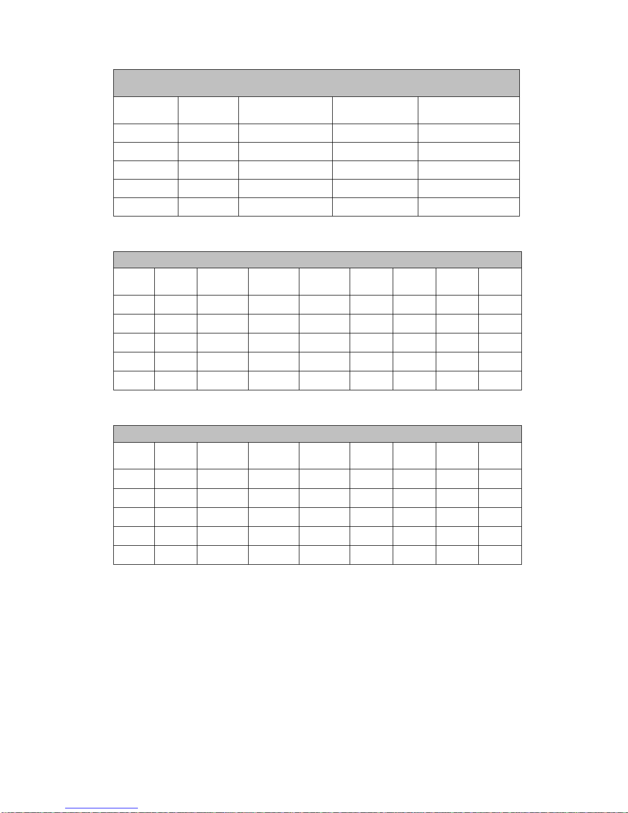
DC power ranges (Auto or Manual)(40 ranges) Range 0.001W to 16KW
Max Power (W) value determined by max voltage gear.
Voltage
Gear
Current
Gear
CF3 Range
CF9 Range
Resolution
10V
0.01~20A
0W~200W
0W~200W
0.001W
30V
0.01~20A
0W~600W
0W~600W
0.001W
100V
0.01~20A
0W~2000W
0W~2000W
0.001W/1W(K)
300V
0.01~20A
0W~6000W
0W~6000W
0.001W/1W(K)
600V
0.01~20A
0W~12KW
0W~12KW
0.01W/1W(K)
Power range with CF 3 setting
Voltage
Range
0.01A
0.03A
0.1A
0.3A
1A
3A
10A
20A
10V
0.1W
0.3W
1W
3W
10W
30W
100W
200W
30V
0.3W
0.9W
3W
9W
30W
90W
300W
600W
100V
1W
3W
10W
30W
100W
300W
1KW
2KW
300V
3W
9W
30W
90W
300W
900W
3KW
6KW
600V
6W
18W
60W
180W
600W
1.8KW
6KW
12KW
Power range with CF 9 setting
Voltage
Range
0.01A
0.03A
0.1A
0.3A
1A
3A
10A
20A
10V
0.3W
1W
3W
10W
30W
100W
200W
200W
30V
0.9W
3W
9W
30W
90W
300W
600W
600W
100V
3W
10W
30W
100W
300W
1KW
2KW
2KW
300V
9W
30W
90W
300W
900W
3KW
6KW
6KW
600V
18W
60W
180W
600W
1.8KW
6KW
12KW
12KW
Page 57
2015/7/09 Version
56
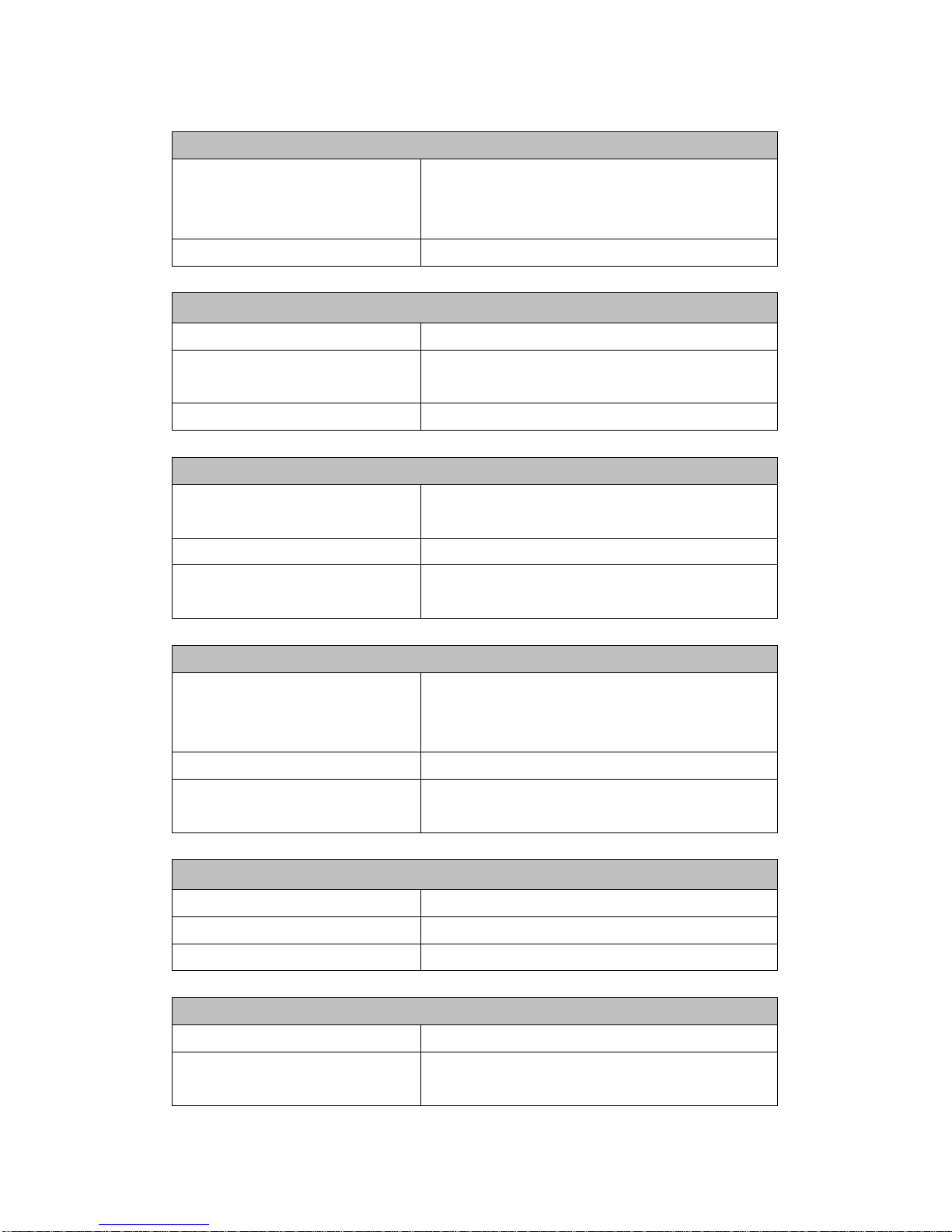
Total Harmonic Distortion (THD)
Frequency Range,
Fundamental
(Automatic Tuned)
40Hz ~ 440Hz
Measuring Input
Voltage or Current
Frequency (Hz)
Operating Principle
Digital frequency detector
Accuracy (23°C±5°C
Environmental)
±0.5% reading
Measuring Input
Voltage or Current Peak Voltage (Vpkp, Vpkn, Vpp)
Ranges (Auto or Manual) (5
Range)
10V(16V), 30V(48V), 100V(160V),
300V(480V), 600V(800V)
Frequency Range
15Hz to 100kHz
Accuracy (23°C±5°C
Environmental)
±3% reading ±3% range ±(0.01*F kHz)%
Peak Current(Ipkp, Ipkn, Ipp)
Ranges (Auto or Manual) (8
Range)
0.01A(0.0215), 0.03A(0.0645), 0.1A(0.215),
0.3A(0.645), 1A(2.15A), 3A(6.45A),
10A(21.5A), 20A(50A peak)
Frequency Range
15Hz to 100kHz
Accuracy (23°C±5°C
Environmental)
±3% reading ±3% range ±(0.2*F kHz)%
Crest Factor (CF)
Computation
Peak/RMS
Current input
CF3(1~3.0) / CF 9.0(1~9)
Voltage Input
CF 2.2 (1~2.2)
Inrush Current
Ranges (Manual) (8 Range)
60mApk to 66 Apk (20A)
Accuracy (23°C±5°C
Environmental)
±5% of selected range
Page 58
2015/7/07 Version
57
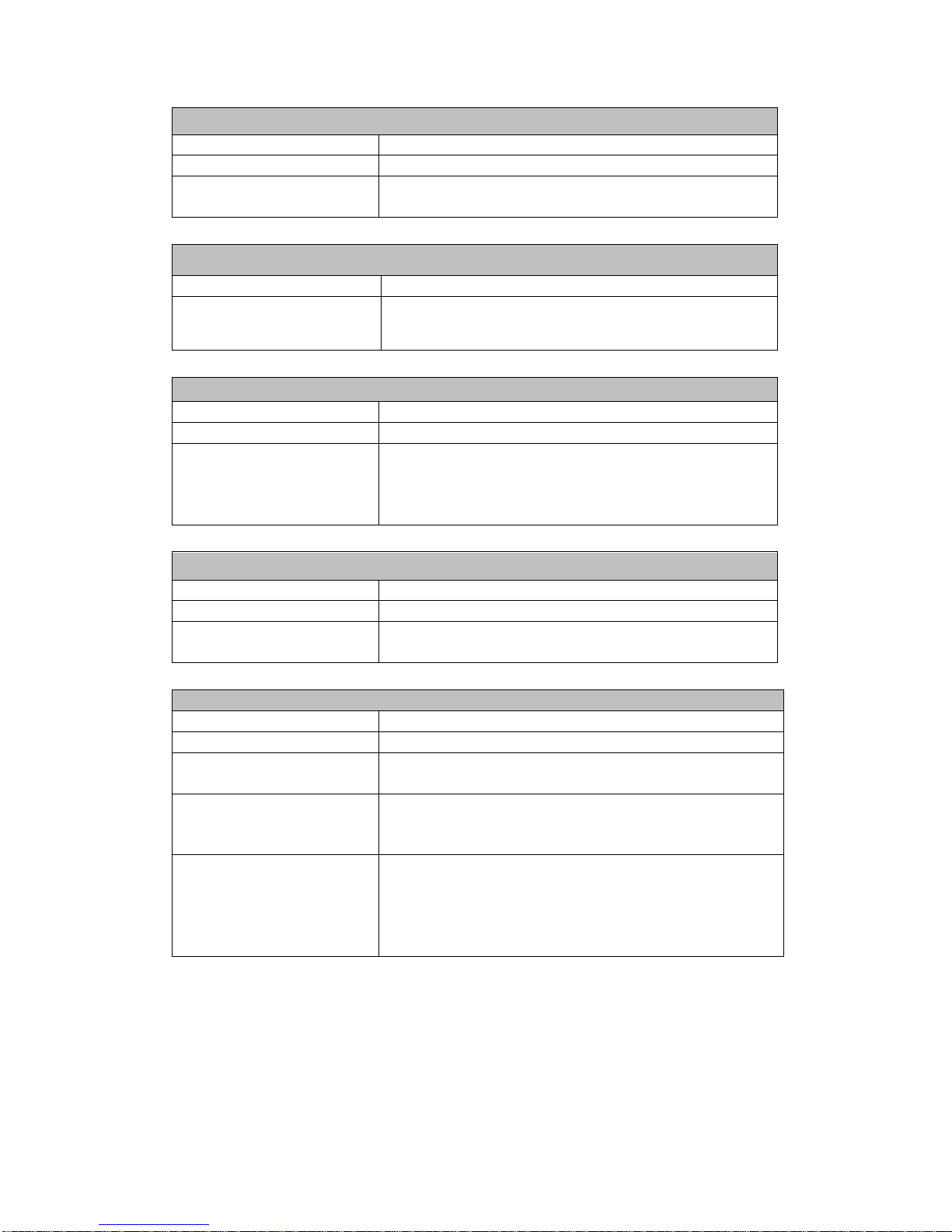
Power Factor (PF)
Ranges
0.0000 to ±1.0000
Computation
W / ( VA)
Accuracy (23°C±5°C
Environmental)
Phase Angle (DEG)
Ranges
0.00 to ±180.00
Computation
DEG = ACOS(PF) with lead/lag detection.
Apparent Power (VA)
Ranges
V A Range
Computation
VrmsΧArms
Accuracy (23°C±5°C
Environmental)
When power factor (PF) = 0(VA: apparent power)
• Add ±0.2% of VA for 45 Hz<f<66 Hz.
• Add ±{(0.2 + 0.2×f)% of VA} for up to 100 kHz as
reference data. The unit for frequency f is kHz.
Reactive Power (var)
Ranges
V A Range
Computation
√((VΧA)
2
-W2 )
Accuracy (23°C±5°C
Environmental)
VA accuracy * PF accuracy
Frequency Precision & Frequency Sensitivity
Frequency Range
Range
15HZ ~ 100KHZ
Accuracy
Precision 0.5% of reading (standard sin wave
signal requires 30%)
Sensitivity
Conditions:
1. Voltage signal must be 30% of voltage gear
2. Current signal must be 30% of current gear
Description
Precision is maintained by the sine wave. Different
testing items have different current gear settings
and have different reference frequencies for
measuring e.g.
variable/high-frequency/oscillating/loading
Page 59
2015/7/09 Version
58
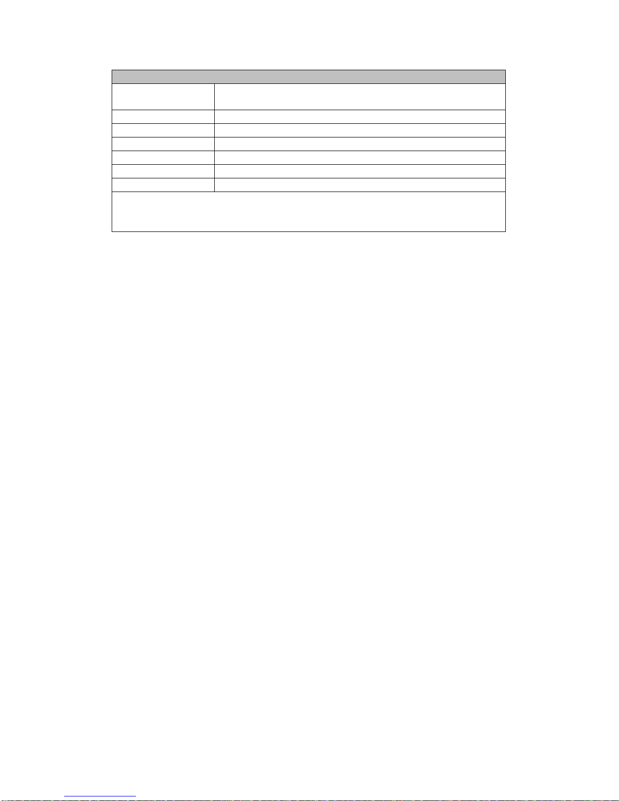
Minimum Measuring Signal Frequency Range at Different Update Rates
Update Time
(sec)
Frequency Range
0.1
25HZ ~ 100KHZ
0.25
10HZ ~ 100KHZ
0.5
5HZ ~ 100KHZ
1
2.5HZ ~ 100KHZ
2
1.5HZ ~ 100KHZ
5
0.5HZ ~ 100KHZ
Description: Measuring range is 15Hz-100KH (update time set to 0.25s); at
0.1 seconds, precision of any values measured below the measuring range
cannot be guaranteed.
Page 60
2015/7/07 Version
59
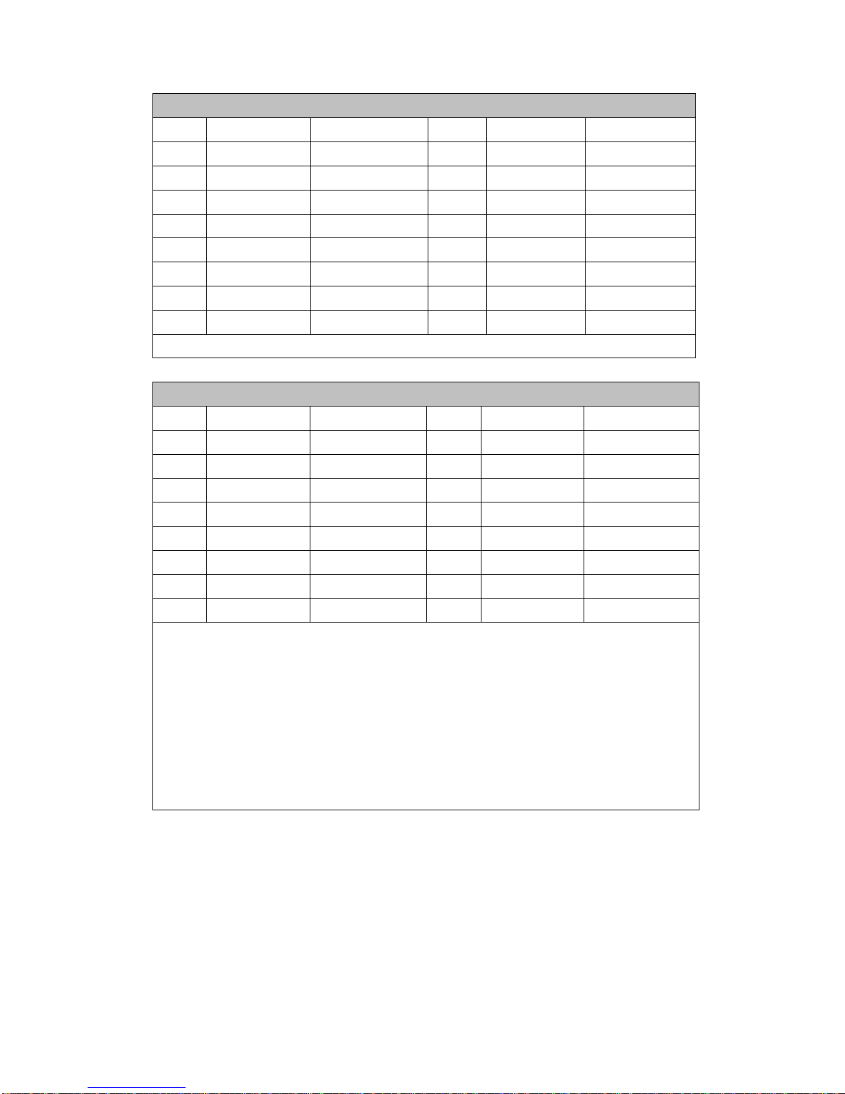
DC Gear Measurement Specifications
MIN
MAX
MIN CF3 / 9
MAX CF3 / 9
10V
1%
210%
0.01A
2% / 6%
260% / 780%
30V
1%
210%
0.03A
2% / 6%
260% / 780%
100V
1%
210%
0.1A
2% / 6%
260% / 780%
300V
1%
210%
0.3A
2% / 6%
260% / 780%
600V
1%
133%
1A
2% / 6%
260% / 780%
3A
2% / 6%
260% / 666%
10A
2% / 6%
200%
20A
2% / 6%
100%
Accessory Specification Conditions:
AC Gear Measurement Specifications
MIN
MAX
MIN CF3 / 9
MAX CF3 / 9
10V
1%
160%
0.01A
2% / 6%
215% / 645%
30V
1%
160%
0.03A
2% / 6%
215% / 645%
100V
1%
160%
0.1A
2% / 6%
215% / 645%
300V
1%
160%
0.3A
2% / 6%
215% / 645%
600V
1%
130%
1A
2% / 6%
215% / 645%
3A
2% / 6%
215% / 645%
10A
2% / 6%
200%
20A
2% / 6%
100%
Accessory Specification Conditions:
a. The above AC Current Measurement Verifications used a Fluke
5522A calibrator. Once current output reached 70% of the
equipment 2.99999A gear power rating maximum current a
low-frequency adjuster LCOMP function was used to adjust output
to contain some high-frequency noise.
b. All AC voltage range and current range were tested and verified
with standard SIN waves.
Page 61
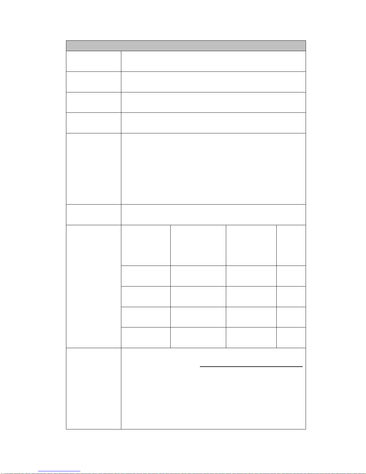
2015/7/07 Version
60
Harmonics Analysis Function Specification
Analysis
Foundation
Obtain a stable base frequency (less than 1% variation)
from voltage or current (non-variable) and begin analysis.
Frequency
Range
45Hz ~ 440Hz
FFT Data
Length
1024
FFT Data
Format
32 bits
Measurement
Items:
1-50 Total Harmonics Distortion, 1-50 Stage Voltage/Current
V[n], A[n],
1-50 Stage Voltage/Current Distortion Ratio V[n%], A[n%]
1-50 Stage Wattage W[n]
1-50 Wattage Distortion Ratio W[n%]
1-50 Stage Voltage and Current Angle DEG[n]
Vrms, Irms, Watt, PF
Window
function
Rectangular
Sampling
Specifications
and Analysis
Stages
Base
Frequency
Sample rate
FFT Data
Base
Frequency
Intervals
MAX.
Order
45≦ F<70
Base
Frequency*512
2
50
70≦ F<130
Base
Frequency*512
2
50
130≦ F<250
Base
Frequency*512
2
50
250≦ F<440
Base
Frequency*512
2
30
Add ±0.2% of range to normal measurement. However, for n
th
order component input, add (n
th
order reading)*(10/n+1) %
to (n-1) order and (n+1) order.
Example: 10V@60Hz 0.1A@600Hz sin wave, 10th order
current display 0.1A, current values for adjacent stages
calculated thus:
Page 62

2015/7/09 Version
61
9 10 11
Up to 50 th order
Accuracy
9th order Maximum Tolerance 0.1A * (10/10+1))% =
0.0018A~0.0022A
11th order Maximum Tolerance 0.1A * (10/10+1)% =
0.0018A~0.0022A
Harmonic
Analysis
with Line filter
specifications
Base
Frequency
-3dB
Frequency
Deadline Frequency Stages
(Degredation ~0.707)
50Hz
~500HZ
10TH
60Hz
~500HZ
~8TH
100Hz
~500HZ
5TH
250Hz
~500HZ
2TH
A/D Conversion
Rate
23040 SPS (45Hz) ~ 225280SPS (440Hz)
A/D Precision
16Bits
FFT Conversion
Precision
32Bits
Panel Update
Rate
0.25s / 0.5s / 1s / 2s / 5s
0.1A
0.0022A
0.0022A
Energy
Page 63
2015/7/09 Version
62
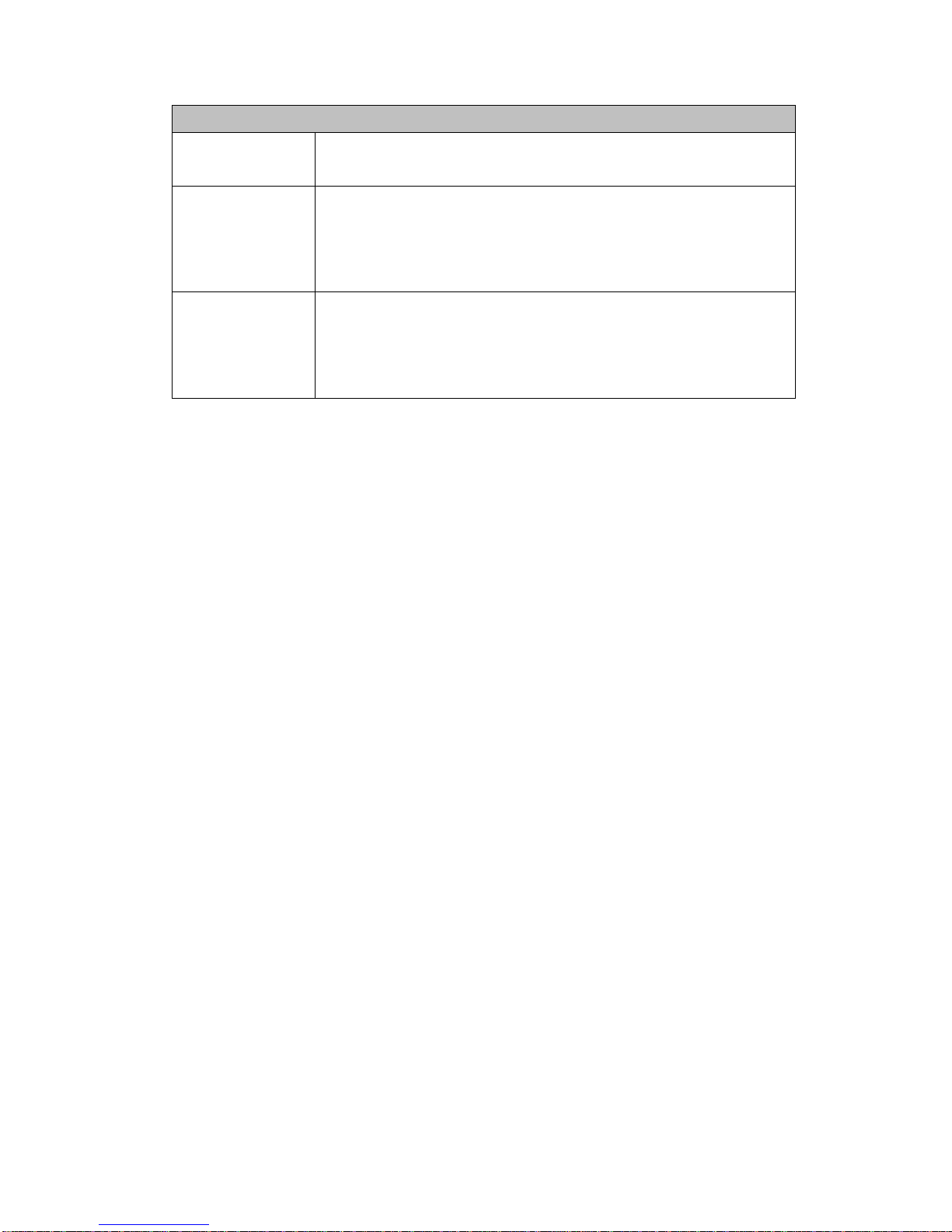
Common mode voltage Specifications
Testing Method
V+, V- Input Terminal Short Circuit, I+,I- open circuit, Apply
AC voltage between CASE & V+ and test.
Voltage
Specifications
< Voltage * F * 0.3 /1000
F = KHz Unit
For example 600V 10KHz:
600V *10 *0.3 /1000 = 1.8V
Current
Specifications
< Voltage * F * 0.01 / 1000000
F = KHz Unit
For example 600V 10KHz
600V *10 *0.01 /1000000 = 0.00006A
Page 64
2015/7/09 Version
63
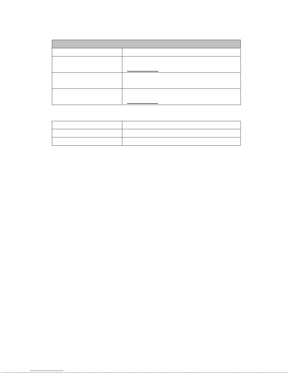
Voltage & Current channel cross talk Specifications
Current Testing Method
V+, V- Input Voltage, I+,I- Idle Contact
Voltage Effects on Current
Specifications
<0.0005% * F of Voltage/100
F = KHz Unit
Voltage Testing Method
I+, I- Input Current, V+,V- use 5cm wire short
circuit
Current Effects on Voltage
Specifications
<0.0005% * F * Current
F = KHz unit
Storage Temperature
-10°C ~ 60°C
Operating Temperature
23°C ~ ±5°C
Operating Humidity
30% ~ 75%
Page 65
64
Chapter 7 GPIB Instruction Sets
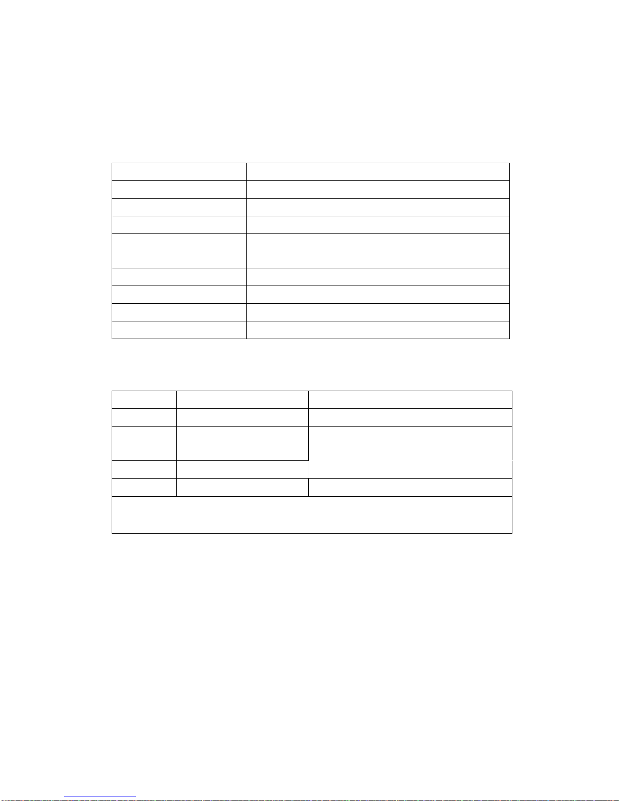
Section 7.1 Serial Communications Specifications
Electrical characteristics
RS232
Connection
Point-to-point
Communications
Full-duplex
Synchronization
Start-stop system
Baud rate
19200/38400/57600/115200 (can change
settings)
Start bit
1 bit
Data length
8 bits
Parity
No parity
Stop bit
1 bit
Section 7.2 Symbols
Symbol
Description
Example
< >
Defined value
DISP<X>, <X>=1 to 3
{ }
One of the options in {}
is selected
MODE{RMS | VME | DC | HARM}
|
Exclusive OR
[ ]
Abbreviated
[:CONF]:VOLT:AUTO = :VOLT:AUTO
Section 7.3 Commands
Command Description
COMMunicateG roup
:COMMunicate:LOCKout Sets/cancels local lockout.
:COMMunicate:REMote Sets remote/local condition.
CONFigure Group
:CONFigure? Queries all settings related to the measurement conditions.
[:CONFigure]:AVERaging? Queries all settings related to the averaging
function.
Page 66

2015/7/09 Version
65
[:CONFigure]:AVERaging[:STATe] Sets/queries averaging ON/OFF.
[:CONFigure]:AVERaging:TYPE Sets/queries averaging type and coefficient.
[:CONFigure]:CURRent? Queries all settings related to the current range.
[:CONFigure]:CURRent:AUTO Sets/queries the current auto range ON/OFF.
[:CONFigure]:CURRent:RANGe Sets/queries the current range.
[:CONFigure]:FILTer Sets/queries the frequency filter ON/OFF.
[:CONFigure]:LFILter Sets/queries the line filter ON/OFF.
[:CONFigure]:MHOLd[:STATe] Sets/queries the MAX hold ON/OFF.
[:CONFigure]:MODE Sets/queries the measurement mode.
[:CONFigure]:SCALing? Queries all settings related to the scaling function.
[:CONFigure]:SCALing:{PT|CT|SFACtor}?
Queries all settings related to scaling constants for {voltage|current|power}.
[:CONFigure]:SCALing:{PT|CT|SFACtor}[:ALL]
Sets the scaling constants for all elements of {voltage|current|power}.
[:CONFigure]:SCALing:{PT|CT|SFACtor}:ELEMent1
Sets the scaling values for each element of {voltage|current|power}.
[:CONFigure]:SCALing[:STATe] Sets/queries the scaling function ON/OFF.
[:CONFigure]:SYNChronize Sets/queries the measurement synchronization
source.
[:CONFigure]:VOLTage? Queries all settings related to the voltage range.
[:CONFigure]:VOLTage:AUTO Sets/queries the voltage auto range ON/OFF.
[:CONFigure]:VOLTage:RANGe Sets/queries the voltage range.
DISPlay Group
:DISPlay<x>? Queries all the display settings.
:DISPlay<x>:ELEMent Sets/queries the element to be displayed.
:DISPlay<x>:FUNCtion Sets/queries the function to be displayed.
:DISPlay<x>:MODE Sets/queries the contents of the display.
:DISPlay<x>:RESolution Sets/queries the number of display digits.
HARMonics Group
:HARMonics? Queries all settings related to harmonic measurement.
:HARMonics:DISPlay? Queries all settings related to the display in case of
harmonic measurement.
:HARMonics:DISPlay:ORDer Sets/queries the order of the harmonic
component to be shown on display B.
:HARMonics:ELEMent Sets/queries the element for harmonic measurement.
:HARMonics[:STATe] Sets/queries the harmonic measurement mode ON/OFF.
:HARMonics:SYNChronize Sets/queries the input to be used as PLL source.
:HARMonics:THD Sets/queries the computation method for harmonic
Page 67

2015/7/09 Version
66
distortion.
INTEGrate Group
:INTEGrate? Queries all settings related to integration.
:INTEGrate:MODE Sets/queries the integration mode.
:INTEGrate:RESet Resets the integration values.
:INTEGrate:STARt Starts integration.
:INTEGrate:STOP Stops integration.
:INTEGrate:TIMer Sets/queries the integration timer.
MATH Group
:MATH? Queries all settings related to the computing function.
:MATH:CFACtor Sets/queries the computing equation of the crest factor.
MEASure Group
:MEASure? Queries all settings related to measurement/computation data.
:MEASure:HARMonics? Queries all settings related to harmonic measurement
data.
:MEASure:HARMonics:ITEM? Queries all settings related to the output items
of harmonic measurement data.
:MEASure:HARMonics:ITEM:PRESet Sets the ON/OFF pattern for all
communication outputs of the harmonic measurement function.
:MEASure:HARMonics:ITEM:{SYNChronize|<harmonic measurement
function>}
Sets/queries the communication output item of harmonic measurement
ON/OFF.
:MEASure:HARMonics:VALue? Queries harmonic measurement data set by
commands other than “MEASure:HARMonics:ITEM” (ASCII format).
:MEASure:NORMal? Queries all settings related to normal
measured/computed data.
:MEASure[:NORMal]:ITEM? Queries all settings related to the output items of
normal measured/computed data.
:MEASure[:NORMal]:ITEM:PRESet Sets the ON/OFF pattern for all
communication outputs of the normal measurement function.
:MEASure[:NORMal]:ITEM:{TIME|MATH} Sets/queries the ON/OFF state of
the communication output of {integration time|MATH}.
:MEASure[:NORMal]:ITEM:<normal measurement function>?
Queries communication output settings of the normal measurement function.
:MEASure[:NORMal]:ITEM:<normal measurement function>:ELEMent1
Sets/queries the communication output items concerning each element
ON/OFF.
Page 68

2015/7/09 Version
67
:MEASure[:NORMal]:VALue? Queries normal measured/computed data set by
commands other than“MEASure[:NORMal]:ITEM” (ASCII format).
RECall Group
:RECall? Queries all settings related to recalling data.
:RECall:INTerval Sets/queries the recalling interval.
:RECall:PANel Retrieves the setup parameters file.
:RECall[:STATe] Sets/queries recalling ON/OFF.
SAMPle Group
:SAMPle? Queries all settings related to sampling.
:SAMPle:HOLD Sets/queries to hold the output of data (display,
communication).
:SAMPle:RATE Sets the display update rate or queries the current setting.
STATus Group
:STATus:ERRor? Queries the occurred error code and message.
STORe Group
:STORe? Queries all settings related to storing data.
:STORe:INTerval Sets/queries the interval for storing data.
:STORe:PANel Saves the setup parameters to a file.
:STORe[:STATe] Sets/queries the store function ON/OFF.
Common Command Group
*CAL? Executes zero-level compensation and queries the results.
*CLS Clears the standard event register, extended event register and error
queue.
*ESE Sets/queries the value of the standard event enable register.
*ESR? Sets/queries the value of the standard event register and clears it.
*IDN? Queries the instrument model.
*OPC This command is not supported by this instrument.
*OPC? This command is not supported by this instrument, and is always “1”.
*OPT? Queries installed options.
*PSC Sets/queries whether or not to clear some registers at power ON.
*RST Initializes the setup parameters.
*SRE Sets/queries the value of the service request enable register.
*STB? Queries the value of the status byte register.
*TRG Executes the same operation as the TRIG(SHIFT+HOLD) key.
*TST? Executes a self-test and queries the results.
*WAI This command is not supported by this instrument.
Communicate group:
COMMunicate:LOCKout
Page 69

2015/7/09 Version
68
Function Sets local lockout ON or OFF.
Syntax COMMunicate:LOCKout {<Boolean>}
Example COMMUNICATE:LOCKout ON
COMMunicate:REMote
Function Sets remote (ON) or local mode (OFF).
Syntax COMMunicate:REMote {<Boolean>}
Example COMMUNICATE:REMOTE ON
Configure group:
CONFigure?
Function Queries all the settings related to the measurement conditions.
Syntax CONFigure?
Example CONFIGURE? ->:MODE DC;:VOLT:RANG 1.000000E+01;:AUTO
1;:CURR:RANG 1.000000E-02;:AUTO 0;:FILT 0;:LFIL 0;:SCAL
0;:SCAL:PT:ELEM1
1.000000E+00;:SCAL:CT:ELEM1 1.000000E+00;:SCAL:SFAC:ELEM1
1.000000E+00;:AVER 0;:AVER:TYPE EXP8;:SYNC V;:MHOL 0
[CONFigure]:AVERaging?
Function Queries all the setting values related to the averaging function.
Syntax [CONFigure]:AVERaging?
Example [CONFIGURE]:AVERAGING? -> :AVER 0;AVER:TYPE EXP8
[CONFigure]:AVERaging[:STATe]
Function Sets averaging ON/OFF, or queries the current status.
Syntax [CONFigure]:AVERaging[:STATe] {<Boolean>}
[CONFigure]:AVERaging:STATe?
Example [CONFIGURE]:AVERAGING:STATE OFF
[CONFIGURE]:AVERAGING:STATE?-> :AVER 0
[CONFigure]:AVERaging:TYPE
Function Sets the averaging type and coefficient, queries the current setting.
Syntax [CONFigure]:AVERaging:TYPE {(LIN|EXP),<NRf>}
[CONFigure]:AVERaging:TYPE?
{<NRf>}=8, 16, 32, 64 (averaging coefficient)
Example [CONFIGURE]:AVERAGING:TYPE LIN,8
[CONFIGURE]:AVERAGING:TYPE?->:AVER:TYPE LIN8
Page 70

2015/7/09 Version
69
[CONFigure]:CURRent?
Function Queries all setting values relating to the current range (external
sensor range)
Syntax [CONFigure]:CURRent?
Example [CONFIGURE]:CURRENT? ->:CURR:RANG 1.000000E-02;AUTO 0
[CONFigure]:CURRent:AUTO
Function Sets the current auto range ON/OFF, or queries the current setting.
Syntax [CONFigure]:CURRent:AUTO {<Boolean>}
[CONFigure]:CURRent:AUTO?
Example [CONFIGURE]:CURRENT:AUTO ON
[CONFIGURE]:CURRENT:AUTO?
->:CURR:AUTO 0
[CONFigure]:CURRent:RANGe
Function Sets the current range, queries the current setting.
Syntax [CONFigure]:CURRent:RANGe {<current>}
[CONFigure]:CURRent:RANGe?
<current> =5mA to 20A
(0.005|0.01,0.02|0.03,0.05|0.1,0.2|0.3,0.5|1,2|3,5|10,20A)
Example Setting of current range/query
[CONFIGURE]:CURRENT:RANGE 20A
[CONFIGURE]:CURRENT:RANGE?-> :CURR:RANG 2.000000E+01
[CONFigure]:FILTer
Function Sets the frequency filter ON/OFF, queries the current setting.
Syntax [CONFigure]:FILTer {<Boolean>}
[CONFigure]:FILTer?
Example [CONFIGURE]:FILTER OFF
[CONFIGURE]:FILTER? ->:FILT 0
[CONFigure]:LFILter
Function Sets the line filter ON/OFF queries the current setting.
Syntax [CONFigure]:LFILter {<Boolean>}
[CONFigure]:LFILter?
Example [CONFIGURE]:LFILTER OFF
[CONFIGURE]:LFILTER?-> :LFIL 0
Page 71

2015/7/09 Version
70
[CONFigure]:MHOLd[:STATe]
Function Sets the MAX hold ON/OFF, queries the current setting.
Syntax [CONFigure]:MHold[:STATe] {<Boolean>}
[CONFigure]:MHold[:STATe]?
Example [CONFIGURE]:MHOLD:STATE OFF
[CONFIGURE]:MHOLD:STATE? ->:MHOL 0
[CONFigure]:MODE
Function Sets the measurement mode of current and voltage, queries the
current setting.
Syntax [CONFigure]:MODE {RMS|VMEan|DC|HARMonics}
[CONFigure]:MODE?
Example [CONFIGURE]:MODE RMS
[CONFIGURE]:MODE? -> :MODE RMS
[CONFigure]:SCALing?
Function Queries all settings relating to the scaling function.
Syntax [CONFigure]:SCALing?
Example [CONFIGURE]:SCALING? -> :SCAL 0;:SCAL:PT:ELEM1
1.000000E+00;:SCAL:CT:ELEM1 1.000000E+00;:SCAL:SFAC:ELEM1
1.000000E+00
[CONFigure]:SCALing:{PT|CT|SFACtor}[{:ALL|ELEM1}]
Function Sets the scaling constants for element1 of{voltage|current|power} at
once. queries the current setting.
Syntax [CONFigure]:SCALing:{PT|CT|SFACtor}[{:ALL|ELEM1}] {<NRf>}
{<NRf>}=0.001 to 9999
Example [CONFIGURE]:SCALING:PT:ALL 1.000
[CONFIGURE]:SCALING:PT:ALL?-> :SCAL:PT:ELEM1 1.000000E+00
Description The setting values are rounded as follows.
Less than 1.000 : Three digits after the decimal point are valid.
1.000 to 9999 : The first five digits are valid.
[CONFigure]:SCALing[:STATe]
Function Sets scaling ON/OFF, queries the current setting.
Syntax [CONFigure]:SCALing[:STATe] {<Boolean>}
[CONFigure]:SCALing:STATe?
Page 72

2015/7/09 Version
71
Example [CONFIGURE]:SCALING:STATE OFF
[CONFIGURE]:SCALING:STATE?-> :SCAL 0
[CONFigure]:SYNChronize?
Function Sets the measurement synchronization source/queries the current
setting.
Syntax [CONFigure]:SYNChronize {VOLTage|CURRent|AUTO|OFF}
[CONFigure]:SYNChronize?
Example [CONFIGURE]:SYNCHRONIZE VOLTAGE?
[CONFIGURE]:SYNCHRONIZE? ->:SYNC V
[CONFigure]:VOLTage?
Function Queries all settings relating to voltage range.
Syntax [CONFigure]:VOLTage?
Example [CONFIGURE]:VOLTAGE? -> :VOLT:RANG 1.000000E+01;AUTO 1
[CONFigure]:VOLTage:AUTO
Function Sets the voltage auto range ON/OFF, queries the current setting.
Syntax [CONFigure]:VOLTage:AUTO {<Boolean>}
[CONFigure]:VOLTage:AUTO?
Example [CONFigure]:VOLTage:AUTO ON
[CONFIGURE]:VOLTAGE:AUTO?-> :VOLT:AUTO 1
[CONFigure]:VOLTage:RANGe
Function Sets the voltage range/queries the current setting.
Syntax [CONFigure]:VOLTage:RANGe {<voltage>}
[CONFigure]:VOLTage:RANGe?
<voltage>=10V to 600V (10, 15|30,60|100,150|300, 600V)
Example [CONFIGURE]:VOLTAGE:RANGE 600V
[CONFIGURE]:VOLTAGE:RANGE?-> :VOLT:RANG 6.000000E+02
[CONFigure]:ACLINE
Function Sets the ACLINE /queries the current setting.
Syntax [CONFigure]:ACLINE {<acline>}
[CONFigure]:VOLTage:RANGe?
< acline >= (50HZ,60HZ)
Example [CONFIGURE]:ACLINE 60HZ
[CONFIGURE]:ACLINE?-> :ACLINE 60Hz
Page 73

2015/7/09 Version
72
[CONFigure]: CFACtor
Function Sets the CFACtor /queries the current setting.
Syntax [CONFigure]:CFACtor {<cfac>},{<elem>}
[CONFigure]:CFACtor?
< cfac >= (3,9)
<elem>=(1)
Example [CONFIGURE]:CFACtor 3,1
[CONFIGURE]:CFACtor?-> :MATH:CFAC 3,1
[CONFigure]: MCMP
Function Sets the MCMP/queries the current setting.
Syntax [CONFigure]:MCMP {<Boolean>}
[CONFigure]:MCMP?
Example [CONFIGURE]:MCMP OFF
[CONFIGURE]:MCMP?-> :MCMP 0
DISPlay<x>?
Function Queries all the display settings.
Syntax DISPlay<x>?
<x>= 1 to 3
1:Display A
2:Display B
3:Display C
Example DISPlay1? -> :DISP:MODE VAL;FUNC V;ELEM 1;RES HIGH
DISPlay<x>:ELEMent
Function Sets the element to be displayed/queries the current setting.
Syntax DISPlay<x>:ELEMent {<NRf>|SIGMa}
DISPlay<x>:ELEMent?
<x>= 1 to 3
1:Display A
2:Display B
3:Display C
{<NRf>}=1
Example DISPLAY1:ELEMENT 1
DISPLAY1:ELEMENT? -> :DISP:ELEM 1
Page 74

2015/7/09 Version
73
DISPlay<x>:FUNCtion
Function Sets the function to be displayed/queries the
current setting.
Syntax DISPlay<x>:FUNCtion {<display function>}
DISPlay<x>:FUNCtion?
<x>= 1 to 3
1:Display A
2:Display B
3:Display C
In case of normal measurement:
<display function>=
{V|A|W|VA|VAR|PF|DEGRee|VHZ|AHZ|WH|WHP|WHM|AH|AHP|AHM
|MATH|VPK|APK|TIME}
In case of harmonic measurement:
<display function>={V|A|W|PF|VHZ|AHZ|VTHD|ATHD|VCON|ACON|WCON
|VDEG|ADEG|ORDer}
Example DISPLAY1:FUNCTION V
DISPLAY1:FUNCTION? -> :DISP:FUNC A
DISPlay<x>:MODE
Function Sets the contents of the display/queries the current setting.
Syntax DISPlay<x>:MODE {VALue|RANGe }
DISPlay<x>:MODE?
<x>= 1 to 3
1:Display A
2:Display B
3:Display C
VALue: displays measurement data
RANGe: displays the present range of voltage and current
Example DISPLAY1:MODE VALUE
DISPLAY1:MODE? -> :DISP:MODE VAL
Description <x> will be ignored. The contents of all the displays A to C will be
received
DISPlay<x>:RESolution
Function Sets the number of displayed digits/queries the current setting.
Syntax DISPlay<x>:RESolution {HIGH|Low}
DISPlay<x>:RESolution?
Page 75

2015/7/09 Version
74
<x>= 1 to 3
1:Display A
2:Display B
3:Display C
Example DISPLAY1:RESOLUTION LOW
DISPLAY1:RESOLUTION? -> :DISP:RES LOW
Description <x> will be ignored. The contents of all the displays A to C will be
received.
DISPlay:INTerval
Function Sets the INTerval ON/OFF, queries the current setting.
Syntax DISPlay: INTerval {<Boolean>}
DISPlay: INTerval?
Example DISPLAY: INTerval OFF
DISPLAY: INTerval? -> :DISP:INT 0;FUNC V;TIM 1
DISPlay:INTerval:FUNCtion
Function Sets the function to be displayed/queries the current setting.
Syntax DISPlay:INTerval:FUNCtion {<display function>}
DISPlay:INTerval:FUNCtion?
In case of RMS&VMEAN Mode:
<display function>={V|A|W|VA|VAR| VCF|ACF|PF}
In case of DC Mode:
<display function>={V|A|W }
In case of HARMONIC Mode:
<display function>={ORDER|V|A|W |PF}
Example DISPLAY:INTerval:FUNCTION V
DISPLAY1:INTerval:FUNCTION? -> :DISP:INT:FUNC V
DISPlay:INTerval:STATe
Function Sets the INTerval ON/OFF, queries the current setting.
Syntax DISPlay:INTerval:STATe {<Boolean>}
DISPlay:INTerval:STATe?
Example DISPLAY:INTerval:STATe OFF
DISPLAY:INTerval:STATe? -> :DISP:INT 0
DISPlay:INTerval:TIMer
Function Sets the INTerval TIMer, queries the current setting.
Page 76

2015/7/09 Version
75
Syntax DISPlay:INTerval:TIMer {<NRf> }
DISPlay:INTerval:TIMer?
<NRf>=1 to 30
Example DISPLAY:INTerval:TIMer 1
DISPLAY:INTerval:TIMer? -> :DISP:INT:TIM 1
DISPlay:INTENsity
Function Sets the INTENsity, queries the current setting.
Syntax DISPlay:INTENsity {<NRf> }
DISPlay:INTerval:INTENsity?
<NRf>=0 to 5
Example DISPlay:INTENsity 3
DISPlay:INTENsity? -> :DISP:INTEN 3
HARMonics?
Function Queries all settings relating to harmonic measurement.
Syntax HARMonics?
Example HARMONICS? -> :HARM 0;HARM:ELEM 1;SYNC V,1;THD
IEC;DISP:ORD 1
HARMonics:DISPlay?
Function Queries all settings concerning the display in case of harmonic
measurement.
Syntax HARMonics:DISPlay?
Example HARMONICS:DISPLAY?
HARMONICS:DISPLAY? -> :HARM:DISP:ORD 1
HARMonics:DISPlay:ORDer
Function Sets the order of the harmonic component to be shown on display A,
queries the current setting.
Syntax HARMonics:DISPlay:ORDer {<NRf>}
HARMonics:DISPlay:ORDer?
{<NRf>}=1 to 50
Example HARMONICS:DISPLAY:ORDER 1
HARMONICS:DISPLAY:ORDER?-> :HARM:DISP:ORD 1
HARMonics:ELEMent
Function Sets the element for harmonic measurement/queries the current
Page 77

2015/7/09 Version
76
setting.
Syntax HARMonics:ELEMent {<NRf>}
HARMonics:ELEMent?
{<NRf>}=1
Example HARMONICS:ELEMENT 1
HARMONICS:ELEMENT?-> :HARM:ELEM 1
HARMonics[:STATe]
Function Sets the harmonic measurement mode ON/OFF, queries the current
setting.
Syntax HARMonics[:STATe] {<Boolean>}
HARMonics[:STATe]?
Example HARMONICS:STATE ON
HARMONICS:STATE? -> :HARM 1
HARMonics:SYNChronize
Function Sets the fundamental frequency for PLL synchronization (PLL
source)/queries the current setting.
Syntax HARMonics:SYNChronize {(V|A|AUTO),(ELEMent<1>)}
HARMonics:SYNChronize?
Example HARMONICS:SYNCHRONIZE V,1
HARMONICS:SYNCHRONIZE?-> :HARM:SYNC V,1
HARMonics:THD
Function Sets the computation method for harmonic distortion (THD) for
harmonic measurement/queries the current setting.
Syntax HARMonics:THD {IEC|CSA}
HARMonics:THD?
Example HARMONICS:THD IEC
HARMONICS:THD? -> :HARM:THD IEC
INTEGrate?
Function Queries all settings relating to integration.
Syntax INTEGrate?
Example INTEGRATE? -> :INTEG:MODE NORM;TIM 00,00,00
INTEGrate:MODE
Function Sets the integration mode/queries the current setting.
Page 78

2015/7/09 Version
77
Syntax INTEGrate:MODE {NORMal|CONTinuous}
INTEGrate:MODE?
Example INTEGRATE:MODE NORMAL
INTEGRATE:MODE?-> :INTEG:MODE NORM
INTEGrate:RESet
Function Resets the integrated values.
Syntax INTEGrate:RESet
Example INTEGRATE:RESET
INTEGrate:STARt
Function Starts integration.
Syntax INTEGrate:STARt
Example INTEGRATE:START
INTEGrate:STOP
Function Stops integration.
Syntax INTEGrate:STOP
Example INTEGRATE:STOP
INTEGrate:TIMer
Function Sets the integration timer/queries the current setting.
Syntax INTEGrate:TIMer {<NRf>,<NRf>,<NRf>}
{<NRf>,<NRf>,<NRf>}=0,0,0 to99,59,59
Example INTEGRATE:TIMER 10,0,0
INTEGRATE:TIMER? -> :INTEG:TIM 10,00,00
MATH?
Function Queries all settings related to the computing function.
Syntax MATH?
Example MATH? -> :MATH:CFAC 9,1
MATH:CFACtor
Function Sets the CFACtor /queries the current setting.
Syntax MATH:CFACtor {<cfac>},{<elem>}
MATH:CFACtor?
< cfac >= (3,9)
<elem>=(1)
Page 79

2015/7/09 Version
78
Example MATH:CFACtor 3,1
MATH:CFACtor?-> :MATH:CFAC 3,1
MEASure?
Function Queries all the settings related to measurement/computation data.
Syntax MEASure?
Example MEASURE? -> :MEAS:ITEM:V:ELEM1 1;:MEAS:ITEM:A:ELEM1
1;:MEAS:ITEM:W:ELEM1 1;:MEAS:ITEM:VA:ELEM1
0;:MEAS:ITEM:VAR:ELEM1 0;:MEAS:ITEM:PF:ELEM1 0;:MEAS:ITEM
MEASure:HARMonics?
Function Queries all settings related to harmonic measurement data.
Syntax MEASure:HARMonics?
Example MEASURE:HARMONICS?-> :MEAS:HARM:ITEM:SYNC 1;VTHD
1;V 1;VCON 1;ATHD 1;A 1;ACON 1;PF 1;W 1;WCON 1;VDEG 1;ADEG 1
MEASure:HARMonics:ITEM?
Function Queries all settings related to the communication output items of
harmonic measurement data.
Syntax MEASure:HARMonics:ITEM?
Example MEASURE:HARMONICS:ITEM? -> (Same result as for
MEASure:HARMonics?)
MEASure:HARMonics:ITEM:PRESet
Function Sets the ON/OFF pattern for all communication outputs of the
harmonic measurement function.
Syntax MEASure:HARMonics:ITEM:PRESet {VPATtern|APATtern|WPATtern|
DPATtern|ALL|CLEar}
Example MEASURE:HARMONICS:ITEM:PRESET VPATTERN
Description The following six patterns can be selected.
VPATtern:SYNChronize/VTHD/V/VCON -> ON, others ->OFF
APATtern:SYNChronize/ATHD/A/ACON -> ON, others ->OFF
WPATtern:SYNChronize/PF/W/WCON -> ON, others ->OFF
DPATtern:SYNChronize/VDEG/ADEG -> ON, others ->OFF
ALL: all items -> ON
CLEar: all items -> OFF
MEASure:HARMonics:ITEM:{ SYNChronize| <harmonicmeasurement
Page 80

2015/7/09 Version
79
function>}
Function Sets the communication output item of harmonic measurement
ON/OFF, queries the current setting.
Syntax MEASure:HARMonics:ITEM:{ SYNChronize|<harmonic measurement
function>} {<Boolean>}
SYNChronize=PLL source
<harmonic measurement function>
={VTHD|V|VCON|ATHD|A|ACON|PF|W|WCON|VDEG|ADEG}
Example MEASURE:HARMONICS:ITEM:VTHD ON
MEASURE:HARMONICS:ITEM:VTHD?-> :MEAS:HARM:ITEM:VTHD 1
Description The selection SYNChronize is for outputting
the frequency of the PLL source.
You can query the PLL source input by the
command HARMonics:SYNChronize?
MEASure:HARMonics:VALue?
Function Queries harmonic measurement data set by commands other than
”MEASure:HARMonics:ITEM” (ASCII format).
Syntax MEASure:HARMonics:VALue?
Example MEASURE:HARMONICS:VALUE? ->
3.362256E+02,9.336657E-04,9.999695E+01,1.852538E+02,.....
MEASure:NORMal?
Function Queries all settings related to normal measured/computed data.
Syntax MEASure:NORMal?
Example MEASURE:NORMAL? -> :MEAS:ITEM:V:ELEM1
1;:MEAS:ITEM:A:ELEM1 1;:MEAS:ITEM:W:ELEM1
1;:MEAS:ITEM:VA:ELEM1 0;:MEAS:ITEM:VAR:ELEM1
0;:MEAS:ITEM:PF:ELEM1 0;:MEAS:ITEM:DEGR:ELEM1
0;:MEAS:ITEM:VHZ:ELEM1 0;:MEAS:ITEM:AHZ:ELEM1
0;:MEAS:ITEM:WH:ELEM1 0;:MEAS:ITEM:AH:ELEM1
0;:MEAS:ITEM:VPK:ELEM1 0;:MEAS:ITEM:APK:ELEM1
0;:MEAS:ITEM:TIME:ELEM1 0
MEASure[:NORMal]:ITEM?
Function Queries all settings related to the communication output items of
normal measured/computed data.
Syntax MEASure[:NORMal]:ITEM?
Page 81

2015/7/09 Version
80
Example MEASURE:NORMAL:ITEM? -> (Results are
the same as for MEASure:NORMal? )
MEASure[:NORMal]:ITEM:PRESet
Function Sets the ON/OFF pattern for all communication outputs of the normal
measurement function.
Syntax MEASure[:NORMal]:ITEM:PRESet {NORMal|INTEGrate|CLEar}
Example MEASURE:NORMAL:ITEM:PRESET NORMAL
Description The following three patterns can be selected.
NORMal: V/A/W -> ON, others -> OFF
INTEGrate: W/WH/AH/TIME -> ON, others ->OFF
CLEar: all items -> OFF
MEASure[:NORMal]:ITEM:{TIME|MATH}
Function Sets the communication output of elapsed integration time ON/OFF,
queries about the current setting.
Syntax MEASure[:NORMal]:ITEM:TIME {<Boolean>}
MEASure[:NORMal]:ITEM:TIME ?
Example MEASURE:NORMAL:ITEM:TIME OFF
MEASURE:NORMAL:ITEM:TIME?-> :MEAS:ITEM:TIME 0
MEASure[:NORMal]:ITEM:<normal measurement function>:ELEMent1
Function Sets the communication output concerning element1 ON/OFF,
queries the current setting.
Syntax MEASure[:NORMal]:ITEM:<normal measurement function>:ELEMent1
{<Boolean>}
<normal measurement function>
={V|A|W|VA|VAR|PF|DEGRee|VHZ|AHZ|WH|WHP|WHM|AH|AHP|AHM|VPK|
APK}
MEASure[:NORMal]:ITEM:<normal measurement function>:ELEMent1?
Example MEASURE:NORMAL:ITEM:V:ELEMENT1 ON
MEASURE:NORMAL:ITEM:V:ELEMENT1?-> :MEAS:ITEM:V:ELEM1 1
MEASure[:NORMal]:VALue?
Function Queries normal measured/computed data set by commands other
than
“MEASure[:NORMal]:ITEM” (ASCII format).
Syntax MEASure[:NORMal]:VALue?
Page 82

2015/7/09 Version
81
Example MEASURE:NORMAL:VALUE?
-> 1.624902E-01,1.737977E-02,1.343538E-03,1.624902E-01,10,00,00,...
Common Command Group
*CAL?
Function Execute zero-level compensation and queries the result.
Syntax *CAL?
Example *CAL? -> 0
Description “0” is returned when the zero-level compensation completes
properly. Otherwise,“1” is returned.
*CLS
Function Clears the standard event register, extended event register and error
queue.
Syntax *CLS
Example *CLS
Description • The output will also be cleared if a *CLS command is appended
after the program message terminator.
*ESE
Function Sets the value for the standard event enable register, or queries the
current setting.
Syntax *ESE {<NRf>}
*ESE?
{<NRf>}=0 to 255
Example *ESE 15
*ESE? -> 15
*ESR?
Function Queries the value of the standard event register and clears it at the
same time.
Syntax *ESR?
Example *ESR? -> 32
Description • Each bit is expressed as a decimal number.
• It is possible to ascertain the type of event which has occurred, while SRQ is
occuring.
Page 83

2015/7/09 Version
82
*IDN?
Function Queries the instrument model.
Syntax *IDN?
Example *IDN? -> MICROTEST, PM7120
Description A reply consists of the following information:<Model>,<Type>
*OPC
Function When *OPC is sent, this command sets bit 0 (the OPC bit) of the
standard event register to “1”.
This command is not supported by this instrument.
Syntax *OPC
*OPC?
Function When *OPC? is sent, “1” in (ASCII code) will be returned.
This command is not supported by this instrument.
Syntax *OPC?
*OPT?
Function Queries installed options.
Syntax *OPT?
Example *OPT? -> HARM,GPIB
Description • “NONE” will be attached to the reply if no options are installed.
*PSC
Function Selects whether or not to clear the following registers when turning
ON the power, or queries the current setting. The registers are the standard
event enable register, the extended event enable register and the transition
filter. However, they cannot be cleared if the parameter is “0.”
Syntax *PSC {<NRf>}
*PSC?
{<NRf>}=0(no clearance), other than 0(clearance)
Example *PSC 1
*PSC? -> 1
This command is not supported by this instrument.
*RST
Function Resets (initializes) the present settings.
Syntax *RST
Page 84

2015/7/09 Version
83
Example *RST
Description initialize settings.
*SRE
Function Sets the value of the service request enable register, or queries the
current setting.
Syntax *SRE {<NRf>}
*SRE?
{<NRf>}=0 to 255
Example *SRE 245
*SRE? -> 181
Description • Each bit is expressed as a decimal number.
*STB?
Function Queries the value of the status byte register.
Syntax *STB?
Example *STB? -> 4
Description • Each bit is expressed as a decimal number.
*TRG
Function Executes the same operation as the TRIG (SHIFT+HOLD) key on the
front panel.
Syntax *TRG
Description Executes the same operation as when using the
multi line message GET.
*TST?
Function Executes a self-test and queries the result. All internal memory
boards are tested.
Syntax *TST?
Example *TST? -> 0
Description “0” will be returned when the result are satisfactory. If an
abnormality is detected, “1”will be returned.
This command is not supported by this instrument.
*WAI
Function Waits for the command following *WAI until execution of the
designated overlap command has been completed.
Page 85

2015/7/09 Version
84
Syntax *WAI
This command is not supported by this instrument.
Page 86
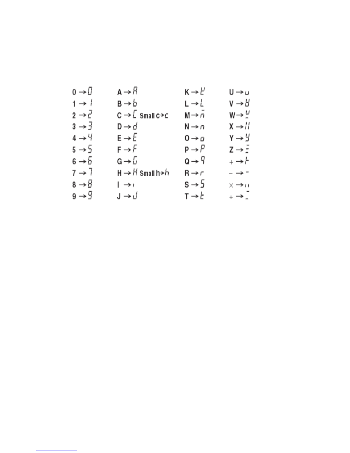
2015/7/09 Version
85
Appendix
Character Chart
Version
V1.0 2015/07/07 Initial Release
V1.01 2015/9/7 Frequencry accuracy & common mode specification change.
 Loading...