

Page 1

OPERATING
MANUAL
model
ACT
-SA
SMOOTH SCROLL
miCRO-TERm,
Inc.
S1.
LOUIS,
MISSOURI
63144
Page 2
OPERATING
MANUAL
MODEL:
SMOOTH
REVISION
ACT
-SA
SCROLL
A,
1-81
SER. # 80340881 and Above
MTI PART *
1-79820013-0A
COPYRIGHT
MICRO-TERM, INC.
1981
Page 3

Page 4
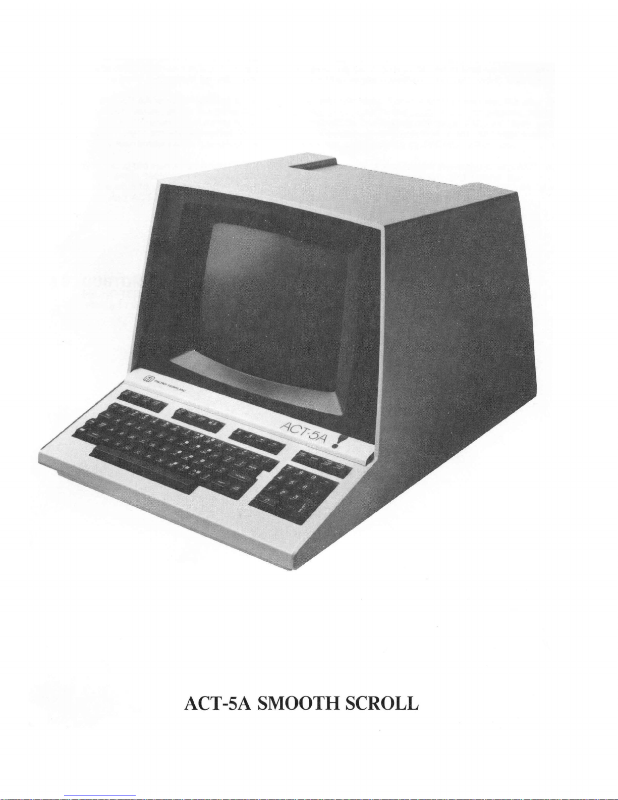
ACT-SA SMOOTH SCROLL
Page 5

Page 6
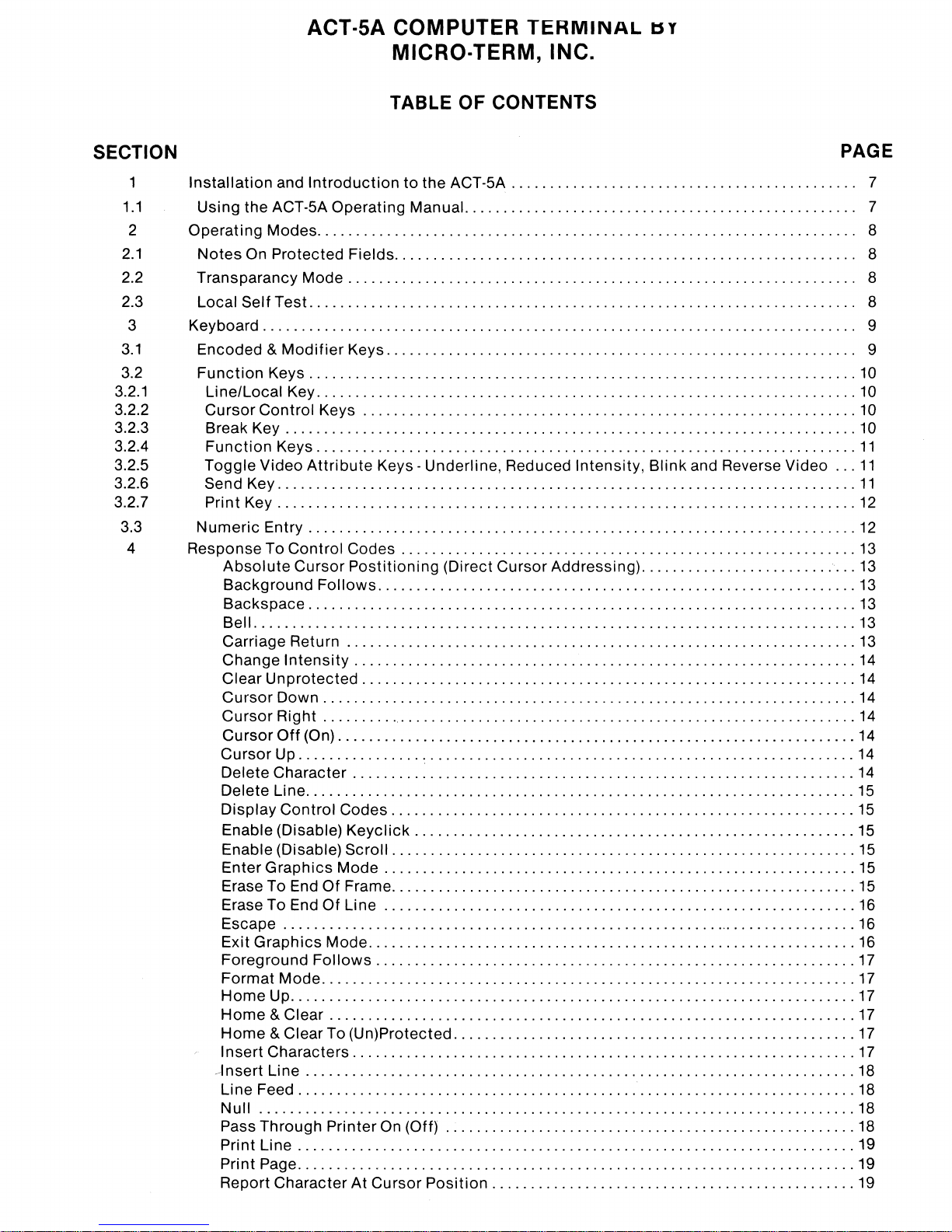
ACT·SA COMPUTER
MICRO·TERM, INC.
TABLE OF CONTENTS
TERMINAL
tsy
SECTION
1
1.1
2
2.1
2.2
2.3
3
3.1
3.2
3.2.1
3.2.2
3.2.3
3.2.4
3.2.5
3.2.6
3.2.7
3.3
4
Installation
Using the ACT-5A Operating Manual. . . . . . . . . . . . . . . . . . . . . . . . . . . . . . . . . . . . . . . . . . . . . . . . .
Operating Modes. . . . . . . . . . . . . . . . . . . . . . . . . . . . . . . . . . . . . . . . . . . . . . . . . . . . . . . . . . . . . . . . . . . .
Notes
Transparancy
Local Self Test. . . . . . . . . . . . . . . . . . . . . . . . . . . . . . . . . . . . . . . . . . . . . . . . . . . . . . . . . . . . . . . . . . . . .
Keyboard
Encoded &
Function
Li
ne/Local Key
Cursor Control Keys
Break Key
Function
Toggle Video
Send Key
Print Key
Numeric
Response To Control Codes
Absolute
Background
Backspace
Bell
Carriage Return
Change
Clear Unprotected
Cursor Down
Cursor Right
Cursor
Cursor Up
Delete Character
Delete Line
Display Control Codes
Enable (Disable)
Enable (Disable) Scroll
EnterGraphics
Erase To End
Erase To End
Escape
Exit Graphics Mode
Foreground
Format Mode
Home
Home
Home
Insert Characters
---Insert
Line Feed
Null
Pass Through Printer On (Off)
Print Line
Print Page
Report Character At Cursor
and
Introduction
On Protected Fields. . . . . . . . . . . . . . . . . . . . . . . . . . . . . . . . . . . . . . . . . . . . . . . . . . . . . . . . . .
Mode.
.............................................................................
Modifier
Keys
.......................................................................
..........................................................................
Keys
Attribute
...........................................................................
........................
Entry
.........................................................
Cursor
.......................................................................
..............................................................................
Intensity
Off
(On)
................
.......................................................................
...........................................................................
Up
.........................................................................
& Clear
& Clear To (Un)Protected
Line
....................................................................
........................................................................
...
' "
........................
........................................................................
........................................................................
. . . . . . . . . . . . . . . . . . . . . . . . . . . . . . . . . . . . . . . . . . . . . . . . . . . . . . . . . . . . . . .
Keys. . . . . . . . . . . . . . . . . . . . . . . . . . . . . . . . . . . . . . . . . . . . . . . . . . . . . . . . . . .
......................................................................
......................................................................
Postitioning
Follows
..................................................................
..............
.....................................................................
.........
...................................................................
.................................................................
Keyclick
Mode
Of
Frame
Of
Line
Follows
.....................................................................
....................................................................
........
to
the ACT-5A . . . . . . . . . . . . . . . . . . . . . . . . . . . . . . . . . . . . . . . . . . .
................................................................
Keys -Underline, Reduced Intensity, Blink and Reverse Video
,
..........................
.............................................
(Direct Cursor Addressing)
..............................................................
,
.........................
................................................................
'.'
..........................................................
:
.......................................................
............................................................
.........................................................
... ' ...............................................
.............................................................
............................................................
.............................................................
...............................................................
..........................................
....................................................
"
........................
,
..............................................
.....................................................
Position
...............................................
,
..............................
,
.......................
,
.............
,
.............
.........................
,
........................
,
...................
,
........
PAGE
..
7
..
7
..
8
..
8
..
8
..
8
9
..
9
10
10
10
10
11
...
11
11
12
12
13
,
..
13
13
13
13
13
14
14
14
14
14
14
14
15
15
15
15
15
15
16
16
16
17
17
17
17
17
17
" .
18
18
18
18
19
19
19
Page 7
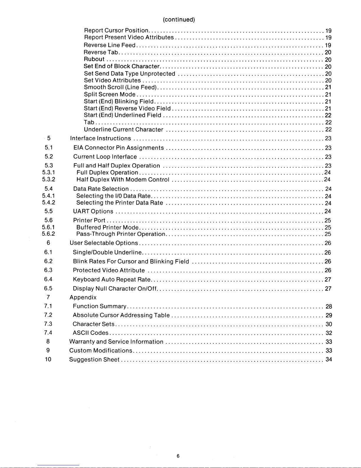
(continued)
Report Cursor
Position
Report Present Video
Reverse Line Feed
Reverse Tab
Rubout
Set
End
Set Send
Set Video
Smooth
Split
Screen Mode
Start (End)
......................................................................
..........................................................................
of
Block
Character
Data Type
Attributes
Scroll (Li ne Feed)
Blinking
Start (End) Reverse Video Field
Start (End) Underlined Field
Tab
..............................................................................
Underline Current
5
5.1
Interface
EIA
Connector
Instructions
Pin
Assignments
5.2 Current Loop Interface
5.3 Full and
5.3.1
5.3.2
Full Duplex Operation
Half
5.4 Data Rate
5.4.1
5.4.2
Selecting
Selecting
5.5 UART
5.6
5.6.1
Printer
Buffered
Half
Duplex Operation
Duplex
With
Selection
the
I/O
Data Rate
Modem
..................................................................
the Printer Data Rate
Options
Port
.......................................................................
..........................................................................
Printer Mode
5.6.2 Pass-Through Printer
6 User Selectable
6.1
6.2
SinglelDouble
Blink
Rates
6.3 Protected Video
6.4 Keyboard
6.5
7
7.1
7.2
7.3
Display
Appendix
Function
Absolute
Character
Null
7.4 ASCII Codes
8 Warranty and
9
10
Custom
Suggestion
Modifications
Options
Underline
ForCursorand
Attribute
Auto
Repeat Rate
Character
Summary
Cursor
Sets
...................................................................
Addressing
.......................................................................
.........................................................................
Service
Information
.................................................................
Sheet
.....................................................................
............................................................
Attributes
...................................................
................................................................
........................................................
Unprotected
..................................................
..............................................................
.........................................................
................................................................
Field
..........................................................
....................................................
Character
............
..... , ....................................
,
..............................
.................................................................
......................................................
...............................................................
.......................................................
...............................................................
Control
....................................................
...........................................................
......................................................
...............................................................
Operation
..... , ..................
,
.............................
...............................................................
..............................................................
Blinking
Field
.............................................
............................................................
...........................................................
On/Off
.........................................................
Table
....................................................
......................................................
,
...........
,
...........
19
19
19
20
20
20
20
20
21
21
21
21
22
22
22
23
23
23
23
24
24
24
24
24
24
25
25
25
26
26
26
26
27
27
28
29
30
32
33
33
34
6
Page 8
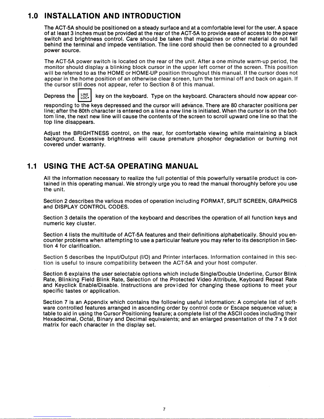
1.0 INSTALLATION AND INTRODUCTION
1.1
The ACT-5A should
of
at least 3 inches
switch
behind the terminal and impede ventilation. The
power source.
The ACT-5A power
monitor
will
appeal in the home position
the cursor
Depress the I
responding
line; after the 80th character is entered on a line a new line is initiated. When the cursor is on the bot-
tom
top
Adjust the
background. Excessive brightness will cause premature phosphor degradation or burning not
covered under warranty.
and brightness control. Care should be taken that magazines or other material do not fall
should display a blinking block cursor in the upper left corner
be
referred
still
to
line,the
line disappears.
next new line will cause the contents
BRIGHTNESS control, on the rear, for comfortable viewing while maintaining a black
USING THE ACT·
All the information necessary
tained in this operating manual. We strongly urge you to read the manual thoroughly before you use
the unit.
be
positioned on a steady surface and at a comfortable level for the user. A space
must
be provided at the rear
switch
to
as the HOME or HOME-UP position throughout this manual. If the cursor does not
does not appear, refer to Section 8
t~t.1
key on the keyboard. Type on the keyboard. Characters should now appear cor-
the keys depressed and the cursor will advance. There are
is located on the rear
of
an otherwise clear screen, turn the terminal
SA
OPERATING MANUAL
to
realize the full potential
of
the ACT-5A
line
cord should then be connected to a grounded
of
the unit. After a one minute warm-up period, the
of
this manual.
of
the screen to scroll upward one line so that the
to
provide ease
of
this powerfully versatile product is con-
of
access to the power
of
the screen. This position
off
and back on again. If
80
character positions per
Section 2 describes the various modes
and DISPLAY CONTROL CODES.
Section
numeric key
Section
counter problems when attempting
tion 4
Section 5 describes the Input/Output (I/O) and Printer interfaces. Information contained in this section is useful to insure
Section 6 explains the user selectable
Rate, Blinking Field
and
specific
Section
ware controlled features arranged in ascending order by control code or Escape sequence value; a
table to aid in using the Cursor Positioning feature; a complete
Hexadecimal, Octal, Binary and Decimal equivalents; and
matrix for each character in the display set.
3 details the operation
cluster.
4
lists
the
multitude
for
clarification.
compatibility
Blink
Keyclick Enable/Disable. Instructions are prov i ded for changing these
tastes or application.
7 is
an
Appendix which contains the following useful information: A complete
of
of
ACT-5A features and
Rate, Selection
of
operation including FORMAT, SPLIT SCREEN, GRAPHICS
the keyboard and describes the operation
their
definitions
to
use a particular feature you may refer
between the ACT-5A and your host computer.
options
which include SinglelDouble Underline, Cursor Blink
of
the Protected Video Attribute, Keyboard Repeat Rate
list
an
enlarged presentation
alphabetically. Should you
of
the ASCII codes including their
of
all function keys and
to
its
description in Sec-
options
to meet your
list
of
the 7 x 9
of
en-
soft-
dot
7
Page 9
2.0 OPERATING MODES
2.1
The ACT-SA
the host computer. Careful study and experimentation
ator
with
Specifically
Codes,
the ACT-SA can present every received code to the operator
Screen mode permits
40
characters), greatly relieving the operator's memory. The Graphics mode
characters that are useful in presenting fractions and graphic data more clearly.
For
efficient
minimize use
the-packet system. The Local mode can also be used
various terminal features.
To further enhance
upon
to
be noted that the Format and
offers
the many powerful
designed
Split
reduce redundant transmissions
a number
to
Screen, and Graphics modes.
twice
communications
of
costly
efficiency
of
useful operating modes that assist the user in
communications
help the user understand the
as many lines
the Local mode
host
CPU
time
or
the Format mode, with associated protected fields, may be called
Split
Screen modes are mutually exclusive.
communication
with
these modes
techniques offered by the ACT-SA.
computer
By
displaying (rather than executing) the control codes
to
be displayed on the screen, (provided they are less than
with
associated editing features may be utilized
to
minimize the number
for
of
forms from the host in data entry applications. It should
outputs
for
debugging assistance. The Split
of
packets transmitted in a pay-by-
testing and studying the operation
will
familiarize the oper-
are the Display the Control
offers
NOTES ON PROTECTED FIELDS
Unlike
the ACT-SA
Video, Blink,
most
computer
allows
or
the user
Underline.
terminals that restrict the protected field video attribute to Reduced Intensity,
to
choose
this
attribute
from Reduced Intensity (Standard), Reverse
a special set
with
of
32
to
of
explicit
For
of
this
of the protected fields feature.
NOTE: Several
unprotected positions. The user should
"protected"
instructions
manual. It is important
when reading about these features.
on
selecting
of
the ESCAPE sequence features discussed in Section 4 refer
to
follow
2.2 TRANSPARENCY MODE
A very useful feature
ASCII control codes when in the Display Control Code mode. This mode can be entered and exited
only by depressing the I CTRL I and G keys simultaneously while in the LOCAL mode. This aids
both the receive and
character received by the terminal
characters.
transmission in
On the transmit side
block mode
of
the ACT-SA is
transmit
to
the computer.
operations.
it
2.3 LOCAL SELF TEST
The LOCAL mode also provides a means
LOCAL mode any problems are
the
the remote computer.
one
these
settling
allows
limited
of
the alternate video attributes, please refer
instructions
substitute
its
capability
On
the receive side it permits one
any format problems caused by otherwise unseen control
control characters
of
testing the terminal manually. If the terminal works in
to
either
carefully in order
his video
to
display a unique symbol for each
the ACT-SA interface, the
attribute
to
be imbedded in the displayed data for
to
selection
insure successful use
communication
to
Section
to
protected or
for
the word
to
identify
of
every
link
6.3
the
or
2.4 X·ON/X·OFF LINE PROTOCOL
Since
honor the X-ON/X-OFF protocol
perform
until
ACT-5A
LINE
this
terminal is equiped
5
jump
the
smooth scroll feature is selected (see section
automatically sends
or
PRINT PAGE operation is initiated.
scroll operations and refrains from sending any X-OFF or
an
with
the SMOOTH SCROLL feature,
to
match the input character rate
4).
X-OFF code when
its
input
8
it
requires the host
to
the scrolling rate. The ACT-5A
X-ON
computer
codes at any
to
time
When SMOOTH SCROLL is selected, the
buffer
is nearly full or when a PRINT
Page 10
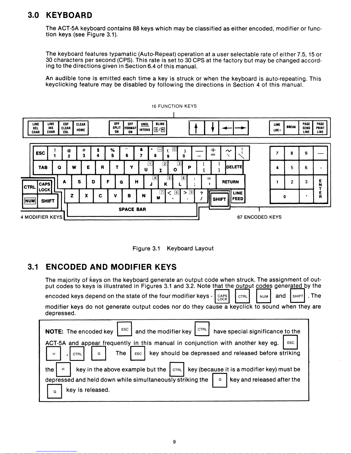
3.0 KEYBOARD
The ACT-5A keyboard contains
tion keys (see Figure
The keyboard features typamatic (Auto-Repeat) operation at a user selectable rate
30
characters per second
ing
to
the directions given in Section 6.4
An audible tone is emitted each time a key is struck or when the keyboard is auto-repeating. This
keyclicking feature may
ESC
3.1).
be
88
keys which may be classified as either encoded,
(CPS).
This rate is set to
of
this
disabled by following the directions in Section 4
16
FUNCTION KEYS
30
CPS
manual.
I t I
at the factory but may
~
I
....
I~I
modifier
of
either
be
changed accord-
of
this
manual.
7
4 5 6
0
7.5,
8
2
or
func-
15
9
3
or
N
T
R
E
E
3.1
ENCODED AND MODIFIER KEYS
The majority
put codes
encoded keys depend on the state
modifier
depressed.
NOTE:
ACT-5A and appear
G
the
depressed and
Figure
of
keys on the keyboard generate
to
keys
is
illustrated in Figures
keys do not generate
The encoded key B and the modifier key I
frequently in
,I
GTRLI
c:=J
c:J
key in the above example but the I
held down while simultaneously striking the
output
The B key should be depressed and released before striking
3.1
Keyboard Layout
an
3.1
and 3.2. Note that the
of
the four modifier keys
codes nor do they cause a keyclick
this
manual in conjunction with another key
GTRL
67
ENCODED KEYS
output code when struck. The aSSignment
-I
f~b~1
GTRL
r have special significance
I key (because
~
rutpr
GTRL
it
is a
key and released after the
code.
El
to
modifier
generated by the
and 1
sound when they are
ego
key) must be
SHIFTI·
to
the
B
of
out-
The
c:J
key is released.
9
Page 11
37 37
37 37
37 37
3434
3434
34 34
31 31
31
31
3838
3838
3838 3939
35 35
35 35
35 35
32 32
31
32 32
31
32 32
30 30
30 30
30 30
2020
39 39
2020
3939
2020
3636
2C 2C
38 36
2C 2C
38 36 2C 2C
3333
3333
0000
3333
0000
0000
2E
2E
2E 2E
2E 2E
3.2 FUNCTION KEYS
Twelve
codes
3.2.1
but
r:;l
of
the
control
KEY
sixteen
various
keys in the
E.I
This key
codes
at
either
codes
the
command
controls
whether
generated by the encoded key are
the
110
or
AUX
generated by the encoded keys are
1/0
or
AUX ports. Data may be sent
as
described
NOTE:
the
invoked
Due
terminal
only
to
the
dramatic
(Enter
Split
by an operator
mode. These features may
minal
the
of
i.e. the same
restricted
the
state
features are ignored when received from the
of
the
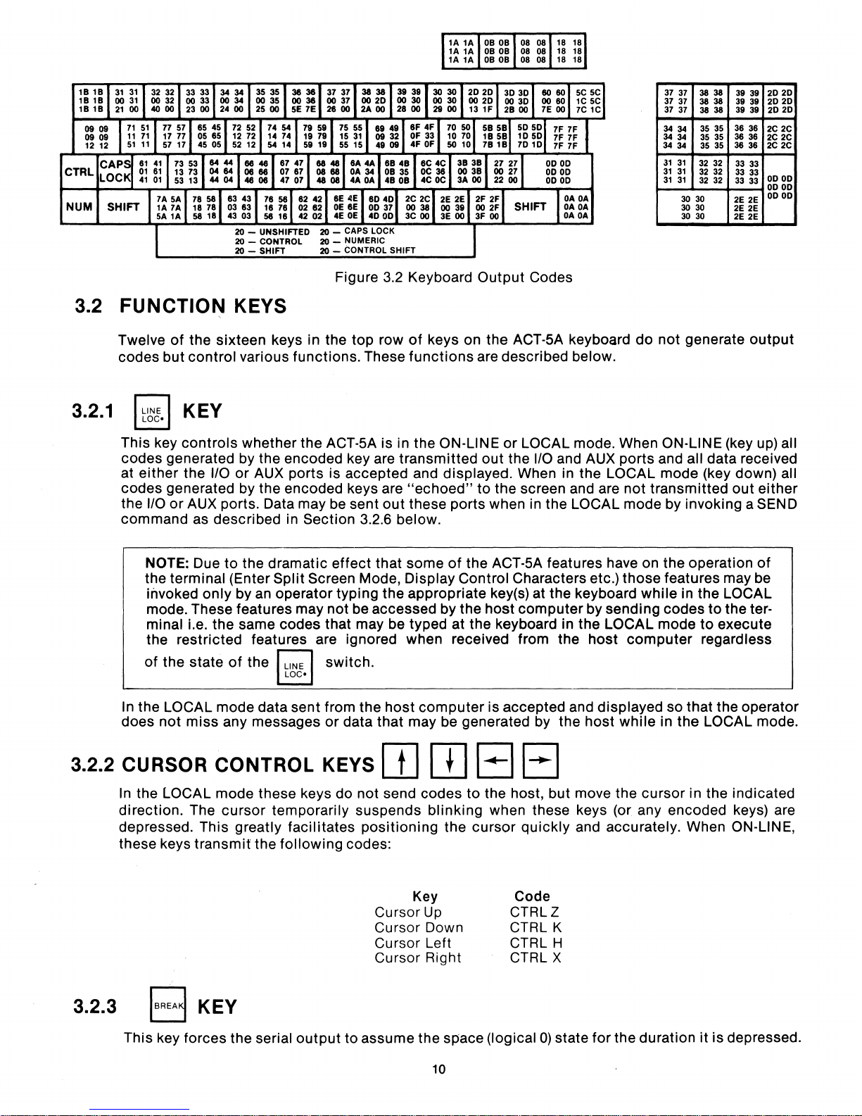
Figure 3.2 Keyboard
top
row
of
keys on
functions.
These
functions
the ACT-SA is in the ON-LINE
transmitted
ports
is
accepted
and displayed. When in the LOCAL
"echoed"
out
these
in
Section
Screen Mode,
codes
r:;l
3.2.6 below.
effect
not
that
that
typing
the
be
accessed
may be typed at
switch.
some
Display
appropriate
by the
E.I
Output
the
Codes
ACT-SA keyboard
do
not
generate
are described below.
or
LOCAL mode. When ON-LINE (key up) all
out
the
110
and AUX
to
the screen and are
ports
when in the LOCAL
of
the ACT-SA features have on the operation
Control
Characters etc.)
key(s) at the keyboard
host
computer
the
keyboard in the LOCAL
by
sending
host
ports
and all data received
mode
(key down) all
not
transmitted
mode
by invoking a SEND
those
features may be
while
in the LOCAL
codes
mode
computer
to
to
regardless
output
out
either
of
the ter-
execute
In the LOCAL
does
not
mode
miss
any messages
data
3.2.2 CURSOR CONTROL KEYS
In the LOCAL
direction.
depressed.
these
keys
3.2.3
B KEY
This key
mode
The
This
transmit
forces
these
cursor
greatly
the
the serial
temporarily
facilitates
following
sent
keys
output
from the
or
data
do
not
suspends
positioning
codes:
Cursor
Cursor
Cursor Left
Cursor Right
to
assume
host
computer
that
may be generated by the
lJJ
send
OJ
codes
blinking
the
Key
is
accepted
B B
to
the host, but move the
when these keys (or any encoded keys) are
cursor
Up
Down
the space (logical
10
quickly
Code
CTRLZ
CTRL K
CTRL H
CTRL X
0)
state
and
displayed
host
while
so
in
the
cursor
that
the
operator
LOCAL mode.
in the
indicated
and accurately. When ON-LINE,
for
the
duration
it
is depressed.
Page 12
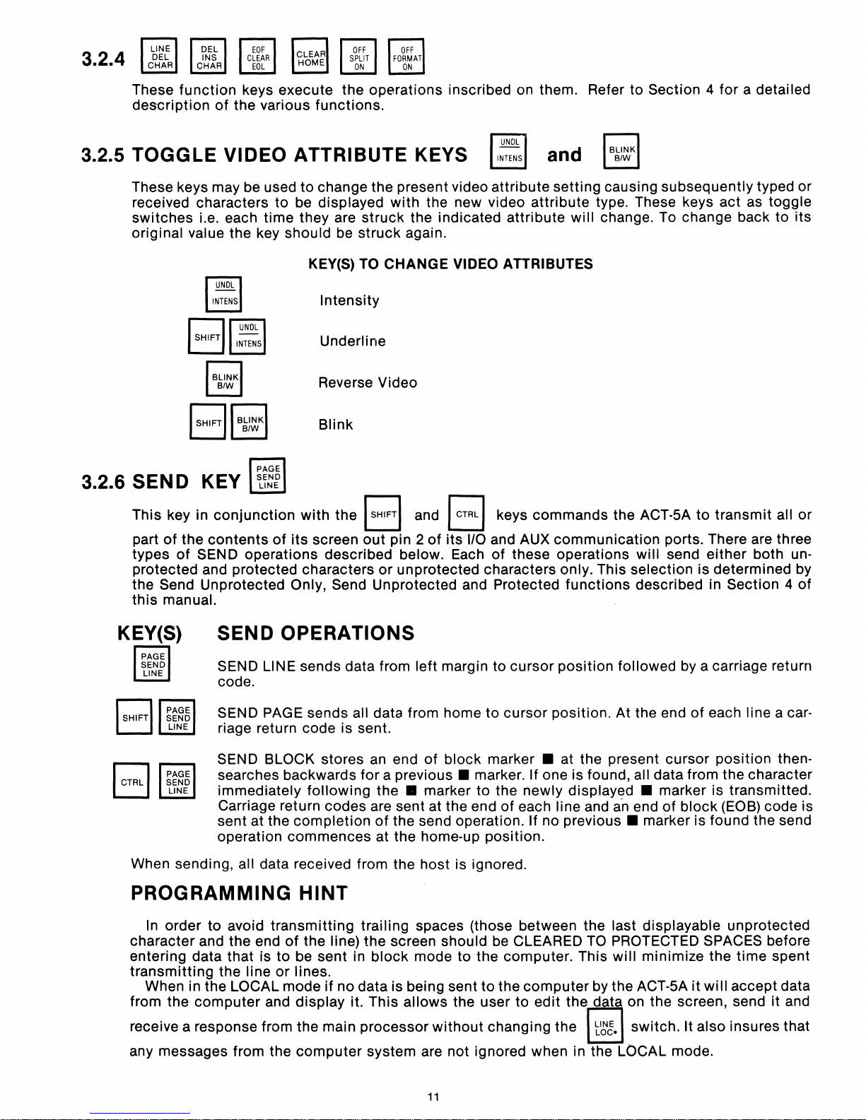
3.2.4
These
description
function
of
keys execute the operations inscribed on them. Refer to Section 4 for a detailed
the various functions.
3.2.5 TOGGLE VIDEO ATTRIBUTE KEYS
These keys may be used
received characters
switches
original value the key should
i.e. each time they are
I BLiNKI
BIW
I SHIFT
/I
BLiNKI
B/W
to
change the present video attribute setting causing subsequently typed or
to
be displayed
KEY(S)
Intensity
Underline
Reverse Video
Blink
with
the new video attribute type. These keys
struck
be
struck again.
TO CHANGE VIDEO ATTRIBUTES
the indicated attribute will change. To change back
3.2.6 SEN D KEY
and
I
BLINKI
B/W
act
as
toggle
to
its
This key in
part
of
types
protected and protected characters
Send Unprotected Only, Send Unprotected and Protected
the
this
manual.
KEY(S)
When sending,
PROGRAMMING
conjunction
the
contents
of
SEND operations described below. Each
of
with
its
the I SHIFTI and I
screen
out
pin 2
or
unprotected characters only. This selection is determined by
of
CTRL
its
1/0
SEND OPERATIONS
SEND LINE sends data from left margin to cursor position followed
code.
SEND PAGE sends all data from home
riage return code is sent.
SEND BLOCK stores
searches backwards for a
immediately
Carriage return codes are sent at the end
sent at the
operation commences at the home-up position.
all data received from the host is ignored.
following
completion
an
end
of
block
previous.
the.
of
marker to the newly
the send operation. If no
HINT
I keys commands the ACT-5A
and AUX communication ports. There are three
of
these operations will send
functions
to
cursor position. At the end
marker.
marker. If one is found, all data from the character
of
each line and
at the present cursor
displayed.
previous.
described in Section 4
a-n
end
marker is found the send
to
transmit
either
by
a carriage return
of
each line a car-
position
marker is transmitted.
of
block (EOB) code is
all or
both un-
of
then-
In order to avoid transmitting trailing spaces (those between the last displayable unprotected
character and the end
entering data that is
transmitting
When in the LOCAL mode
the
from
receive a response from the main processor
any messages from the
the line
computer
of
to
or
and display it. This
the line)
be sent in
lines.
if
no data is being sent
computer
the
screen should be CLEARED
block
system are not ignored when in the LOCAL mode.
mode to the computer. This
to
the
computer
allows
the user
without
11
to
edit
changing the
TO
PROTECTED SPACES before
will
by the ACT-5A
thel dati
t~g.
minimize
it
on the screen, send
switch. It also insures that
the
time spent
will
accept data
it
and
Page 13
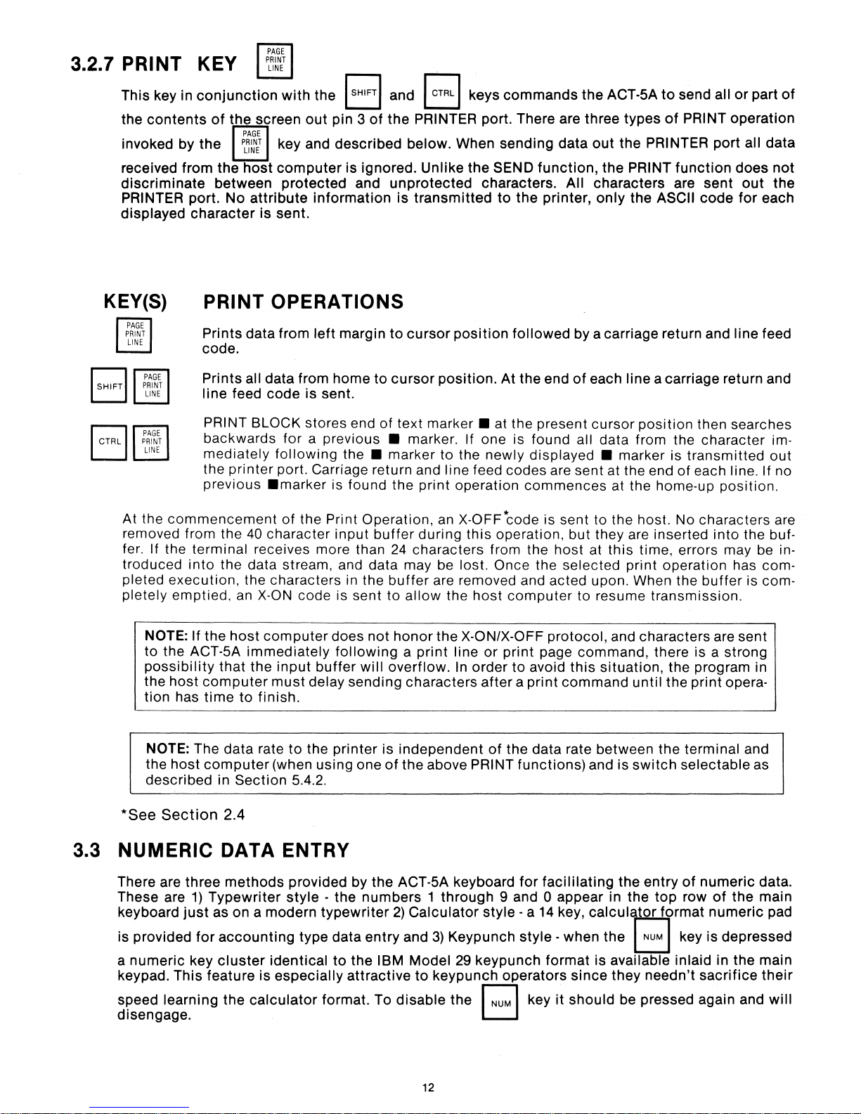
KEY(S)
PRINT OPERATIONS
Prints
code.
Prints
line
At the
removed from the
fer. If the terminal receives more than
troduced
pleted
pletely
commencement
into
execution,
emptied,
NOTE:
to
possibility
the
tion
If
the ACT-SA
host
computer
has
data from
all data from
feed
code
PRINT BLOCK stores end
backwards
mediately
the
printer
previous
the data stream, and data may be lost. Once the
the
that
time
.marker
40
character
the characters in the
an
X-ON code is sent
host
computer
immediately
the
must
to
finish.
left
margin
home
to
is
sent.
for a previous.
following
port. Carriage return and line feed codes are sent at the end
of
the Print Operation,
input
the.
is found the
input
buffer
does
not
following a print
buffer
delay
will
sending
to
cursor
cursor
of
text
marker. If one is found all data from the
marker
24
buffer
to
allow
honor
overflow.
characters
position
position.
marker.
to
the
print
operation
an
X-OFF*code is sent to the host. No characters are
during
characters from the
this
are removed and acted upon. When the
the
the
X-ON/X-OFF
line
In
followed
At the end
at the present
newly
host
or
order
after a print
displayed.
commences
operation,
computer
print
to
avoid
by a carriage return and line feed
of
each line a carriage return and
cursor
marker is
at the home-up
but
they are inserted
host
at
this
selected
to
protocol,
page
command,
this
command
print
resume
and characters are sent
situation,
position
time, errors may be in-
transmission.
there
until
then searches
character
transmitted
of
each line. If no
position.
into
the buf-
operation
the program in
the
has com-
buffer
is a strong
print
opera-
is com-
im-
out
NOTE:
the
described
*See
3.3
NUMERIC
There are
These are
keyboard
is provided
a
numeric
keypad.
speed
disengage.
The
host
computer
Section
three
1)
Typewriter
just
for
key
This
feature
learning
data
rate
to
(when using one
in
Section
2.4
DATA ENTRY
methods
as on a modern
accounting
cluster
the
provided by
style -the
identical
is
especially
calculator
the
printer
5.4.2.
typewriter
type data
to
format. To
is
independent
of
the above PRINT
the
ACT-SA keyboard
numbers 1 through
2)
Calculator
entry
and
3)
Keypunch
the
IBM Model 29
attractive
to
keypunch
disable
12
the
of
the data rate between
functions)
for
facililating
9 and 0 appear in
style
- a
14
key,
style
- when
keypunch
operators
r::l key
format
since
it
should
L..::.J
the
terminal and
and
is
switch
the
the
calculator
the
B key
is
available
they
be pressed again and
selectable
entry
of
top
row
format
inlaid
needn't
numeric
of
the
numeric
is
depressed
in
the
sacrifice
as
data.
main
pad
main
their
will
Page 14
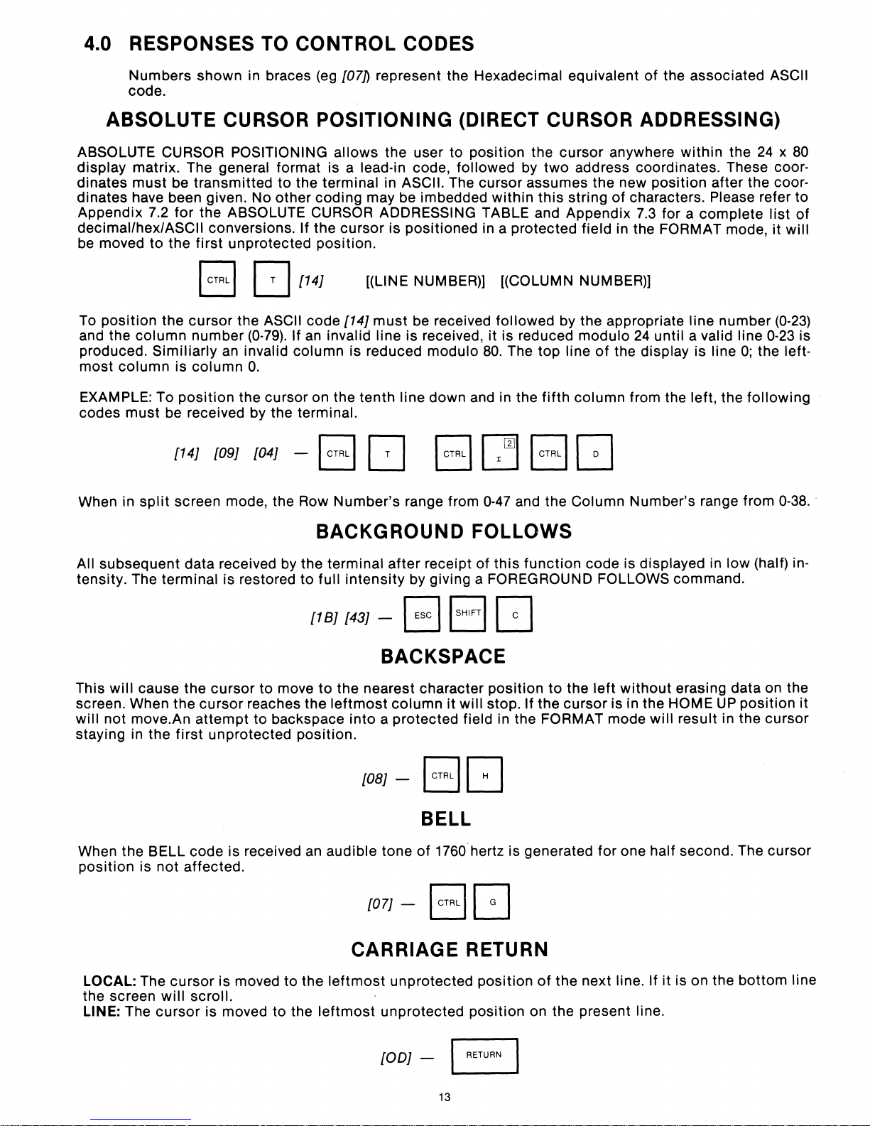
4.0 RESPONSES
TO
CONTROL CODES
Numbers shown in braces
code.
(eg
[07]) represent the Hexadecimal equivalent
of
the associated ASCII
ABSOLUTE CURSOR POSITIONING (DIRECT CURSOR ADDRESSING)
ABSOLUTE CURSOR POSITIONING allows the user to position the cursor anywhere
display matrix. The general format is a lead-in code, followed
dinates
dinates have been given. No other coding may be imbedded within this string
Appendix 7.2 for the
decimal/hex/ASCII conversions. If the cursor is positioned in a protected field in the FORMAT mode,
be
To position the cursor the
and the column number
produced.
most column is
EXAMPLE: To
codes
must
be transmitted
ABSOLUTE CURSOR ADDRESSING TABLE and Appendix
moved to the first unprotected position.
B
Similiarly
must
position
be
[14J [09J
an
column
received by the terminal.
to
the terminal in ASCII. The cursor assumes the new position after the coor-
[J
(0-79).
invalid column is reduced modulo
O.
the cursor on the tenth line down and in the
[04J
[14J
ASCII code [14J
If
an
- I CTRL I
[(LINE NUMBER)] [(COLUMN NUMBER))
invalid line is received,
[J
must
be
received followed by the appropriate line number
I CTRL
II
by
two
address coordinates. These coor-
it
is reduced modulo
80.
The
top
line
fifth
column from the left, the following
}~II
CTRL I G
of
characters. Please refer to
7.3
24
of
the display is line
within
for a complete
until a valid line
the
0;
24 x 80
the left-
list
it
will
(0-23)
0-23
of
is
When in
split
screen mode, the Row Number's range from
0-47
and the Column Number's range from
0-38
BACKGROUND FOLLOWS
All subsequent data received by the terminal
tensity. The terminal is restored
to
full intensity by giving a FOREGROUND FOLLOWS command.
[18J [43J - B I SHIFT I G
after
receipt of
this
function
code is displayed in low (half) in-
BACKSPACE
This
will
cause the cursor
screen. When the cursor reaches
will not move.An attempt to backspace into a protected field in the FORMAT mode will result in the cursor
first
staying in the
unprotected position.
to
move
the
to
the nearest character position
leftmost
[08J
column
-
Bc:J
it
will
stop. If the cursor is in the HOME
to
the
left
without
erasing data on the
UP
position
it
BELL
When the BELL code is received
position is not affected.
an
audible tone
[07J-
of
1760 hertz is generated for one half second. The cursor
BG
..
LOCAL: The cursor is moved to the
the screen
LINE:
The
will
scroll.
cursor
is moved to the
CARRIAGE RETURN
leftmost
leftmost
unprotected position
unprotected position on the present line.
[ODJ
- c::J
13
of
the next line. If
it
is on the bottom line
Page 15
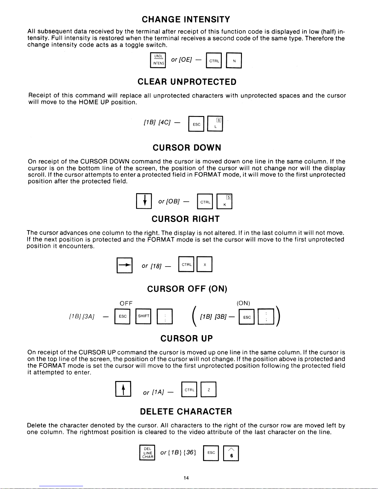
CHANGE
INTENSITY
All subsequent data received by the terminal
tensity. Full
change
intensity
intensity
is restored when the
code
acts
as a
toggle
terminal
switch.
CLEAR UNPROTECTED
Receipt
will
of
move
this
command
to
the HOME
will replace all
UP
position.
unprotected
{1B} {4C} -
CURSOR DOWN
On
receipt
cursor
scroll. If the
position
of
the CURSOR DOWN
is on the
cursor
after
the
bottom
attempts
protected
command
line
of
the screen, the
to enter a protected field in FORMAT mode,
field.
OJ
after
the
or
receipt
receives a second code
or{OE}
cursor
position
{OB}
of
this
- B Q
characters
E1
- B
~
is moved
of
the
c=J
function
with
down
cursor
code
is displayed in
of
the same type. Therefore the
unprotected
one line in the same column. If the
will
not
it
will
move to the
spaces and the
change nor
low
will
the
first
unprotected
(half) in-
cursor
display
The
cursor
If the next
position
On
on the top
the
it
attempted
it
receipt
FORMAT
advances one
position
encounters.
of
line
to
is
protected
{1
B}
{3A}
the CURSOR
of
the screen, the
mode
is set the
enter.
CURSOR RIGHT
column
to the right. The
and the FORMAT mode is set the
I
~
I
or
{18} - B
CURSOR
OFF
BBD
UP
command
position
cursor
[[]
the
of
will
move
or
{1A} - B
display
is not altered. If in the last
[J
OFF
(
[18]{38]
CURSOR UP
cursor
the
is moved up one line in the same column. If the
cursor
to
the
will
not
first
unprotected
[J
cursor
(ON)
(ON)
-
E1
change. If the
position
will
move to the
D)
position
following
column
above is protected and
it
will
not
move.
first
unprotected
cursor
the protected field
is
Delete the
column.
one
character
The
rightmost
denoted by the cursor. All characters to the right
position
DELETE CHARACTER
is cleared
to
or{1B}
the video
{36}
14
attribute
B I
of
the
cursor
of
the last character on the line.
~
I
row are moved
left
by
Page 16
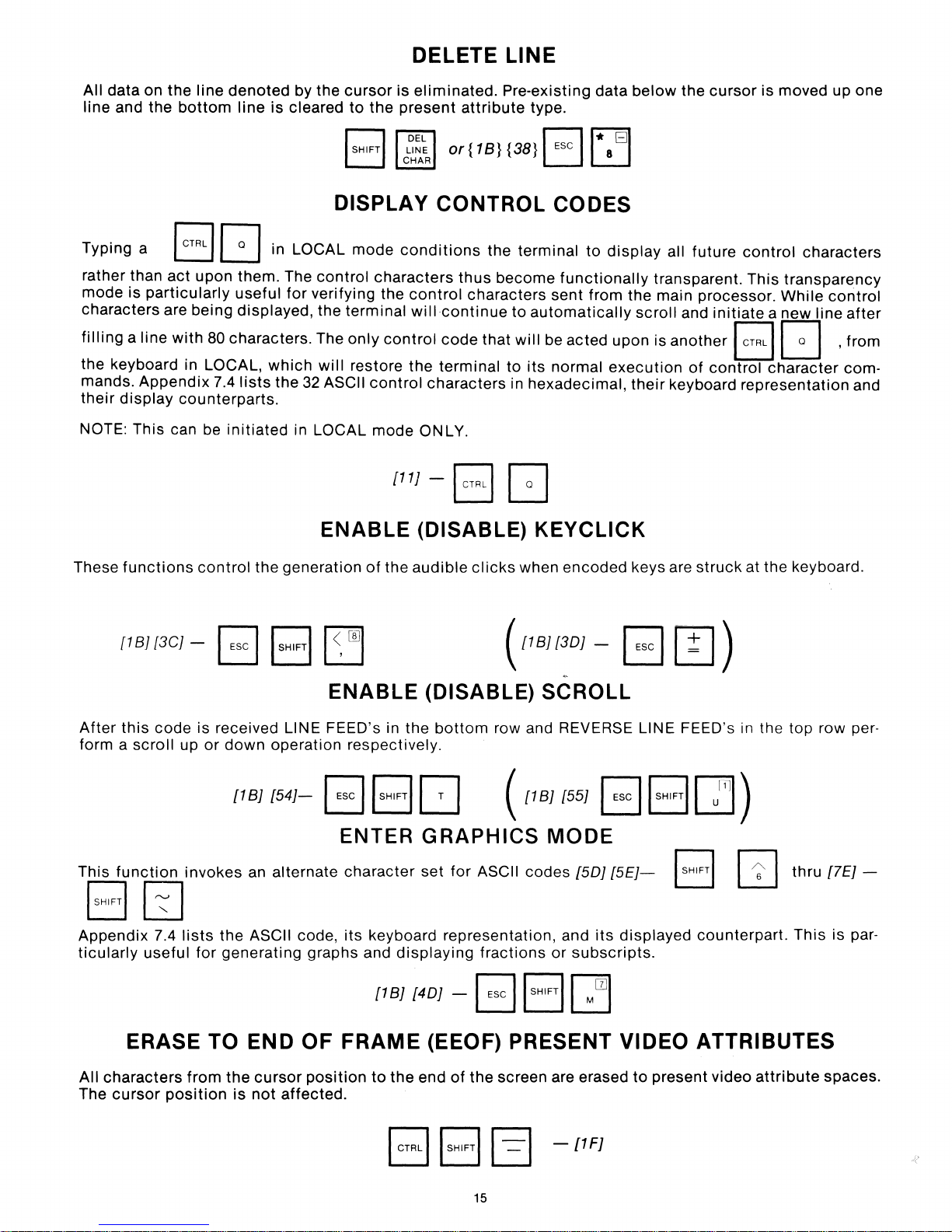
DELETE LINE
All data on
line and
the
the
line
bottom
denoted
line
is
by the
cleared
cursor
to
the
SHIFT
B
DISPLAY
Typing a
rather than
mode
characters are being displayed, the terminal
filling
the keyboard in LOCAL,
mands.
their
display
NOTE: This can be
act
is
particularly
a line
with
Appendix
counterparts.
upon them. The
80 characters. The
7.4
in
useful
which
lists
the
initiated
LOCAL
control
for
verifying the
will
32
ASCII
in LOCAL
mode
characters
only
control
restore
control
mode
{tt]
ENABLE (DISABLE) KEYCLICK
is
eliminated.
present
DEL
LINE
CHAR
attribute
or
{1 B}
CONTROL
conditions
control
will
the
terminal
characters
ONLY.
- B G
the terminal
thus
characters sent from the main processor.
continue
code
that
Pre-existing data
type.
B~El
{38}
ESC
8
CODES
to
become
to
to
in hexadecimal,
functionally
automatically
will
be acted upon is
its
normal
below
display
execution
all
transparent.
scroll
another
their
keyboard representation and
the
future
and
of
cursor
initiate
is moved up one
control
This
a new line
B G
control
character
characters
transparency
While
control
after
,from
com·
These
After
form a
This
functions
[1
BJ
[3CJ
this
code
scroll
function
BGJ
Appendix
ticularly
7.4
useful for generating graphs and
control
- B I
the generation
SHIFTII
~
r~1
ENABLE (DISABLE) SCROLL
is received LINE FEED's in
up
or
down
operation respectively.
{IB]
{54]-
B B 0 (
ENTER
invokes
lists
an
the
ASCII code,
alternate
character
its
of
the
audible
the
GRAPHICS
set
keyboard representation, and
displaying
{t
BJ
{4D] - B I
clicks
({
bottom
row and REVERSE LINE FEED's in the
for
ASCII codes [50J
fractions
when
encoded
IB1I3D
{IB]
(55] B B
MODE
or
subscripts.
SHIFTII
keys are
] - B
[5EJ-
its
displayed
M
wi
struck
0)
m)
I
SHIFTI
counterpart.
at the keyboard.
top
row per·
~
thru
This
[lEJ
is
-
par-
ERASE TO
All characters
cursor
The
from
position
the
is
END
cursor
not
affected.
OF
position
FRAME
to
(EEOF) PRESENT VIDEO ATTRIBUTES
the
end
B B G
of
the
screen are erased
-[1F]
15
to
present video
attribute
spaces.
Page 17
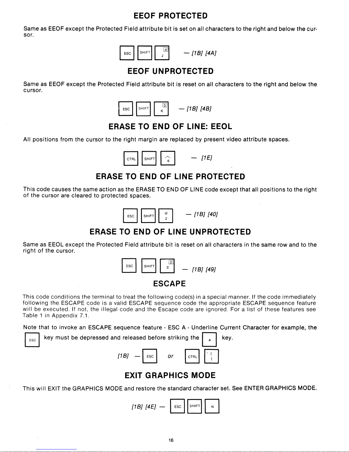
EEOF PROTECTED
Same as EEOF
sor.
Same as EEOF
cursor.
All
positions
This code causes the same
of
the
cursor
except
except
from
are cleared to protected spaces.
the Protected Field
the Protected Field
the
cursor
attribute
EEOF UNPROTECTED
attribute
B I
SHIFT
\I
ERASE TO END
to
the
right
margin are replaced by present video
ERASE TO END
action
as the ERASE
bit
is set on all characters to the
BJ
-
[4AJ
[4BJ
[1EJ
- [1BJ
bit
is reset on all characters to the
KC§JI
OF
TO
-
[1
OF
LINE: EEOL
LINE PROTECTED
END OF LINE code
except
right
attribute
that
all
and
below
right
and
spaces.
positions
the cur-
below
to
the
the
right
B8IT]
ERASE TO END
Same as EEOL
right
of
the cursor.
This code
following
will
be
executed. If not, the illegal code and the Escape code are ignored. For a
Table 1 in Appendix
Note
that to invoke an ESCAPE sequence feature -
B key
except
conditions
the ESCAPE code is a valid ESCAPE sequence code the appropriate ESCAPE sequence feature
must
the Protected Field
the terminal to treat the
7.1.
be depressed and released
[1BJ
EXIT GRAPHICS MODE
OF
attribute
ESCAPE
following
before
-B
-
[1BJ
[40J
LINE UNPROTECTED
bit
is reset on all characters in the same row and
[1BJ
[49J
code(s) in a special manner. If the code
list
of these features see
ESC
A - Underline Current Character
striking
or
the
B
[J
OJ
key.
for
to
the
immediately
example,
the
This
will
EXIT the GRAPHICS MODE and restore the standard character set. See ENTER GRAPHICS MODE.
[1BJ
[4EJ
- B
16
ISHIFTI
[J
Page 18
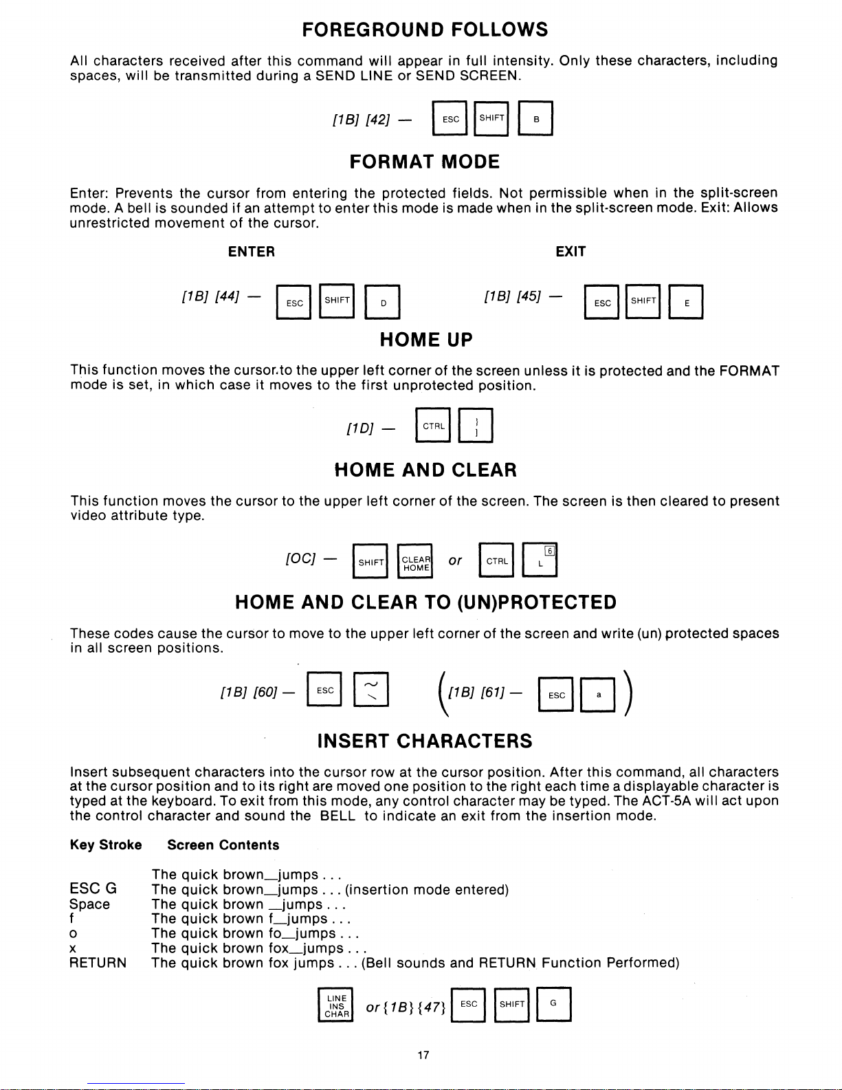
FOREGROUND FOLLOWS
All characters received after this command
spaces,
will
be transmitted during a SEND LINE
[18J [42J - B
FORMAT MODE
Enter: Prevents the
mode. A bell is sounded
unrestricted movement
This
function
mode is set, in
moves the cursor.to the upper
cursor
[18J [44J - B
which
from entering the protected fields. Not permissible when in the split-screen
if
an
attempt to enter
of
the cursor.
ENTER
case it moves to the
ISHIFTI
[10J - B
will
appear in full intensity. Only these characters, including
or
SEND SCREEN.
ISHIFTI
this
mode is made when in the split-screen mode. Exit:
G [18J [45J - B
HOME
left
corner
first
unprotected position.
UP
of
the screen unless
c:J
EXIT
it
ISHIFTI
is protected and the FORMAT
[J
[JJ
Allows
HOME
This function moves the cursor to the upper
video
attribute
type.
[OCJ
-
HOME AND CLEAR TO (UN)PROTECTED
These codes cause the cursor
all screen
in
positions.
[18J [60J - B I
to
move to the upper left corner of the screen and write (un) protected spaces
INSERT CHARACTERS
Insert subsequent characters into the
at the cursor
typed at the keyboard. To
the
control character and sound the BELL
Key Stroke
position
Screen Contents
and
to
its
right are moved one position to the right each
exit
from this mode, any control character may be typed. The ACT-5A
cursor
AND CLEAR
left
corner
:::
I
row at the cursor position.
to
indicate
of
the screen. The screen is then cleared
or
B~
1B
0
) [61} - B
an
exit from the insertion mode.
After
[J
time
)
this
command, all characters
a displayable character is
will
to
present
act upon
The
quick
ESC G
Space
f
o
x
RETURN
The
The
The
The
The
The
quick
quick
quick
quick
quick
quick
brown_jumps
brown_jumps
brown
brown
brown
brown
brown fox
_jumps
f_jumps
fo_jumps
fox_jumps
..
...
..
jumps
.
(insertion mode entered)
.
..
.
..
.
..
.
...
(Bell sounds and RETURN Function Performed)
or{18}
{47} B \SHIFTI8
17
Page 19
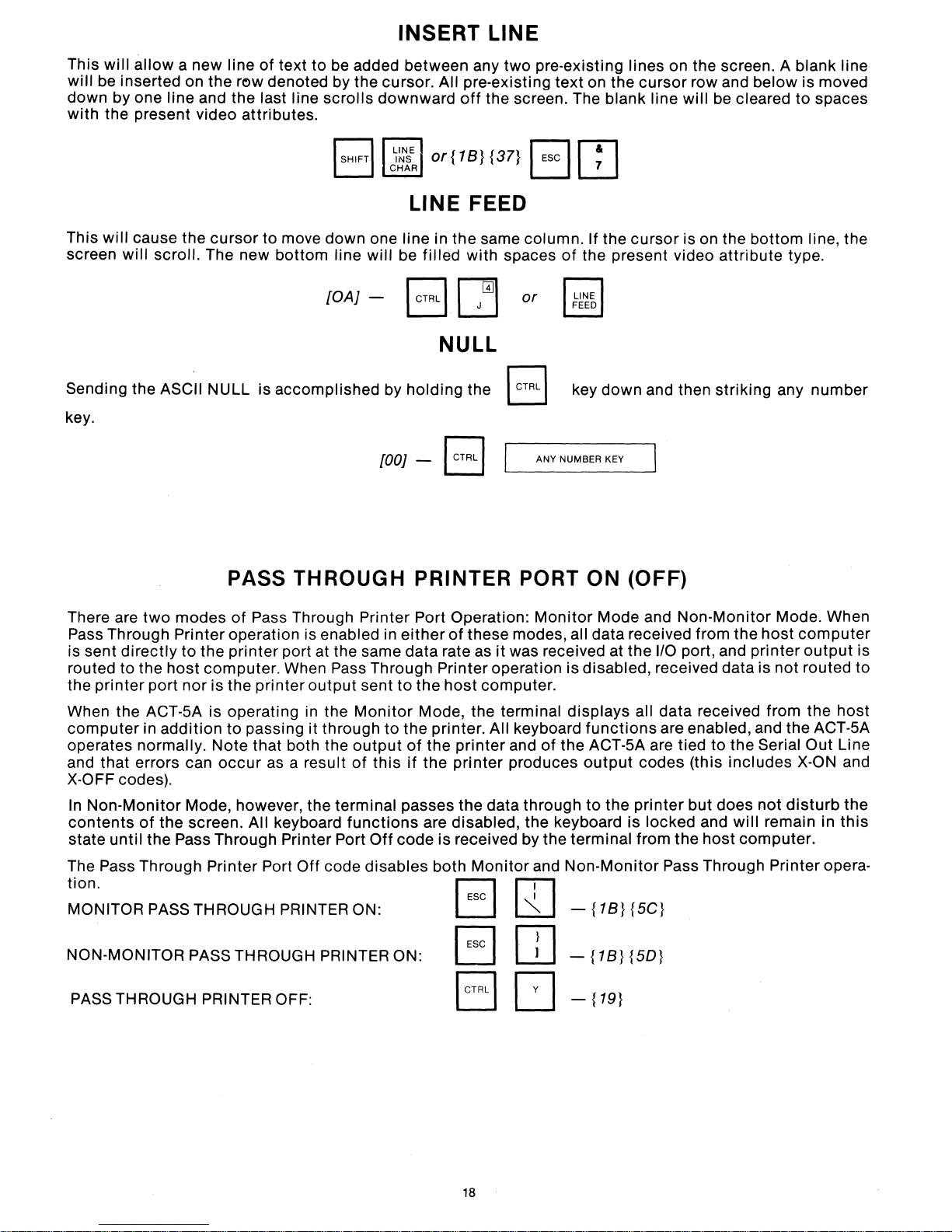
INSERT LINE
This
will
allow
a new line
will
be inserted on the row denoted by the cursor. All pre-existing
down by one line and the last line
with
the present video attributes.
of
text
to
be added between any
scrolls
downward
~Wl
or{18}{37}
CHAR
off
LINE FEED
This
will
screen
cause the
will
scroll. The new
cursor
to move down one line in the same column. If the
bottom
line
will
be
filled
with spaces
two
pre-existing lines on the screen. A blank line
text
on the
the screen. The blank line
~
'--=J
1il7&
L2J
of
the present video attribute type.
cursor
cursor
row and
will
is on the
below
be cleared to spaces
bottom
is moved
line, the
[OAJ - I CTRL I
Sending the ASCII NULL is accomplished by
key.
[OOJ
PASS THROUGH PRINTER PORT ON (OFF)
There are
Pass Through Printer operation is enabled in
is sent
routed
the
printer
When the ACT-5A is operating in the
computer
operates normally.
and that errors can
X-OFF codes).
In
Non-Monitor
contents
state until the Pass Through Printer Port
two
directly
to
the
port
in
addition
of
the
modes
to
host
nor
of
Pass Through Printer Port Operation:
the
printer
computer. When Pass Through Printer operation is disabled, received data is not routed
is the printer
to
Note
occur
Mode, however, the terminal passes the data through
screen. All keyboard
port at the same data rate as it was received at
output
passing it through
that both the
as a result
sent
Monitor
to
output
of
this
functions
Off
c=1
or
r:;l
~
NULL
holding
- B
either
to
the
Mode, the terminal
the printer. All keyboard
of
if
code
the B key
ANY NUMBER KEY
Monitor
of
these modes, all data received from
host
computer.
the
printer
the
printer
are disabled, the keyboard is locked and
is received by the terminal from
and
of
produces
down
and then
Mode and Non-Monitor Mode. When
the
110
displays
functions
the ACT-5A are tied
output
to
all data received from
are enabled, and the ACT-5A
codes
the
printer
striking
port, and printer
to
the Serial Out Line
(this
includes
but
does not
the
host
any
the
host
will
remain in
computer.
number
computer
output
the
host
X-ON and
disturb
is
to
the
this
The Pass Through Printer Port
tion.
MONITOR PASS THROUGH PRINTER ON:
NON-MONITOR PASS THROUGH PRINTER ON:
PASS THROUGH PRINTER OFF:
Off
code disables
both
~
'--=J
B
8
Monitor
18
and
Non-Monitor
rJl
L..:::SJ
[JJ
[]
-
-
-{19}
{18}{5C}
{18}
{5D}
Pass Through Printer opera-
Page 20
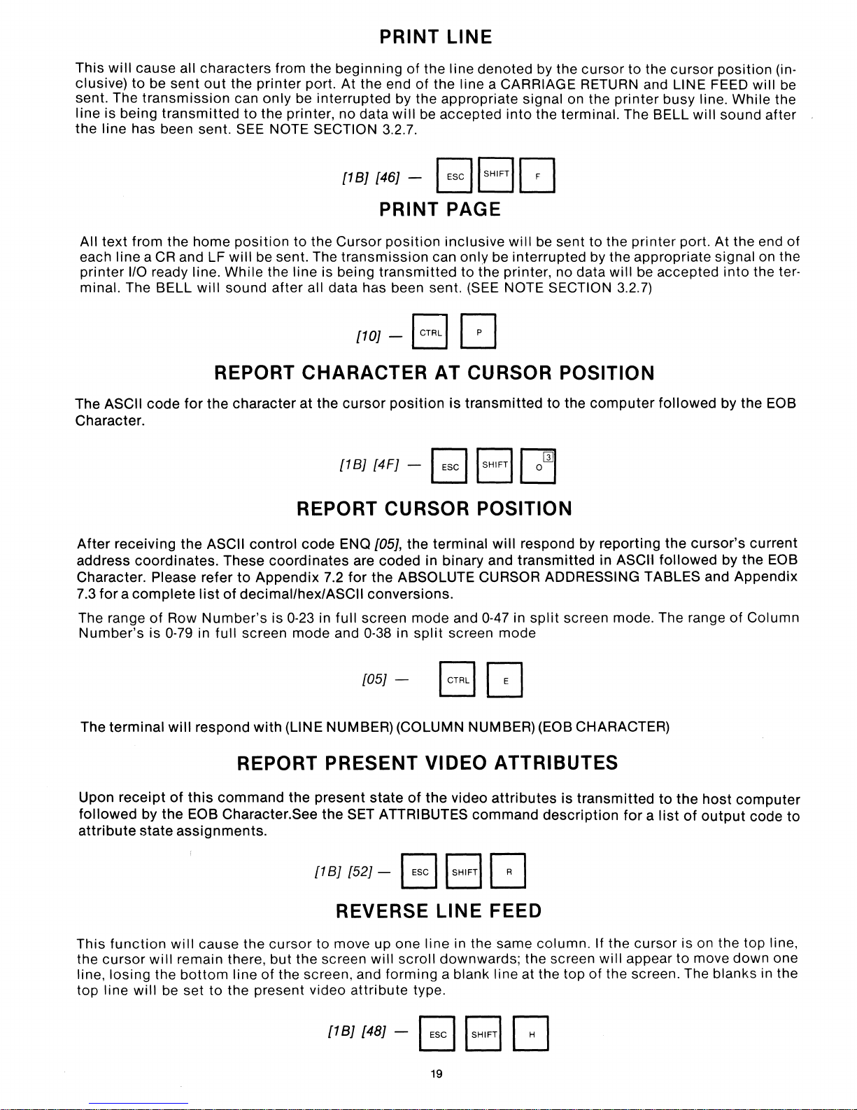
This
will
clusive)
sent. The
line
is
being
the
line
PRINT
cause all characters from the
to
be
sent
out
the
printer
transmission
transmitted
has been sent. SEE NOTE SECTION 3.2.7.
can
to
only
the
printer,
beginning
port.
At
be
interrupted
no
{1BJ
of
the end
by the appropriate signal on the
data
will
{46J
- B
LINE
the line
of
the
be
accepted
denoted
line a CARRIAGE RETURN and LINE FEED
ISHIFTI
by the
into
the terminal. The BELL
cursor
printer
[]
to
the
cursor
busy line.
position
will
While
sound
will
after
(in-
be
the
All
text
from the
each
line a CR
printer
minal. The BELL
1/0
home
and LF
ready line.
will
REPORT
The ASCII
Character.
After
address
Character. Please refer
7.3
for a complete
code
receiving
coordinates.
for
the
the
ASCII
list
position
will
While
sound
to
the
be sent. The
the line is being
after
all data has been sent. (SEE NOTE SECTION 3.2.7)
CHARACTER
character
at
the
REPORT
control
These
to
Appendix
of
decimal/hex/ASCII
code
coordinates
PRINT
Cursor
transmission
transmitted
{10J
cursor
{1BJ
{4FJ
ENQ
[05J,
are
coded
7.2
for
the
conversions.
PAGE
position
-
position
CURSOR
ABSOLUTE CURSOR ADDRESSING TABLES and
inclusive
can
only
to
EJ
[]
AT
is
transmitted
-I
ESC
IISHIFTII
the
terminal
in binary and
will
be sent
be
interrupted
the printer, no data
CURSOR
POSITION
to
the
owl
POSITION
will
respond by
transmitted
to
the
printer
by the
computer
appropriate
will
be
reporting
in ASCII
port.
accepted
followed
the
cursor's
followed
At
the end
signal on the
into
by
the
by the EOB
Appendix
of
the ter-
EOB
current
The range
Number's
The
terminal
Upon
receipt
followed
attribute
This
function
the
cursor
line,
losing
line
top
will
of
Row
Number's
is 0-79 in full screen
will
respond
with
REPORT
of
this
command
by
the
EOB Character.See
state
assignments.
will
cause the
will
remain there,
the
bottom
be set
line
to
the present video
is
0-23 in
mode
(LINE NUMBER) (COLUMN NUMBER) (EOB CHARACTER)
the
cursor
but
of
the screen, and
full
and 0-38 in
PRESENT
present
the
SET ATTRIBUTES
[1
BJ
{52J
REVERSE
to
move up one
the
screen
attribute
screen
[05J
mode
split
-
VIDEO
state
of
the
- B I
line
will
scroll
forming
type.
and 0-47 in
screen
split
mode
ATTRIBUTES
video
attributes
command
SHIFTI
[]
LINE
downwards;
a blank line at the
FEED
in the same
the screen
column.
screen mode. The range
is
transmitted
description
If the
will
top
of
the screen. The
to
for a list
cursor
appear
of
Column
the
host
computer
of
output
is on the top line,
to
move
down
blanks
code
one
in the
to
[1
BJ
{48J
- B I
19
SHIFTI
c:J
Page 21
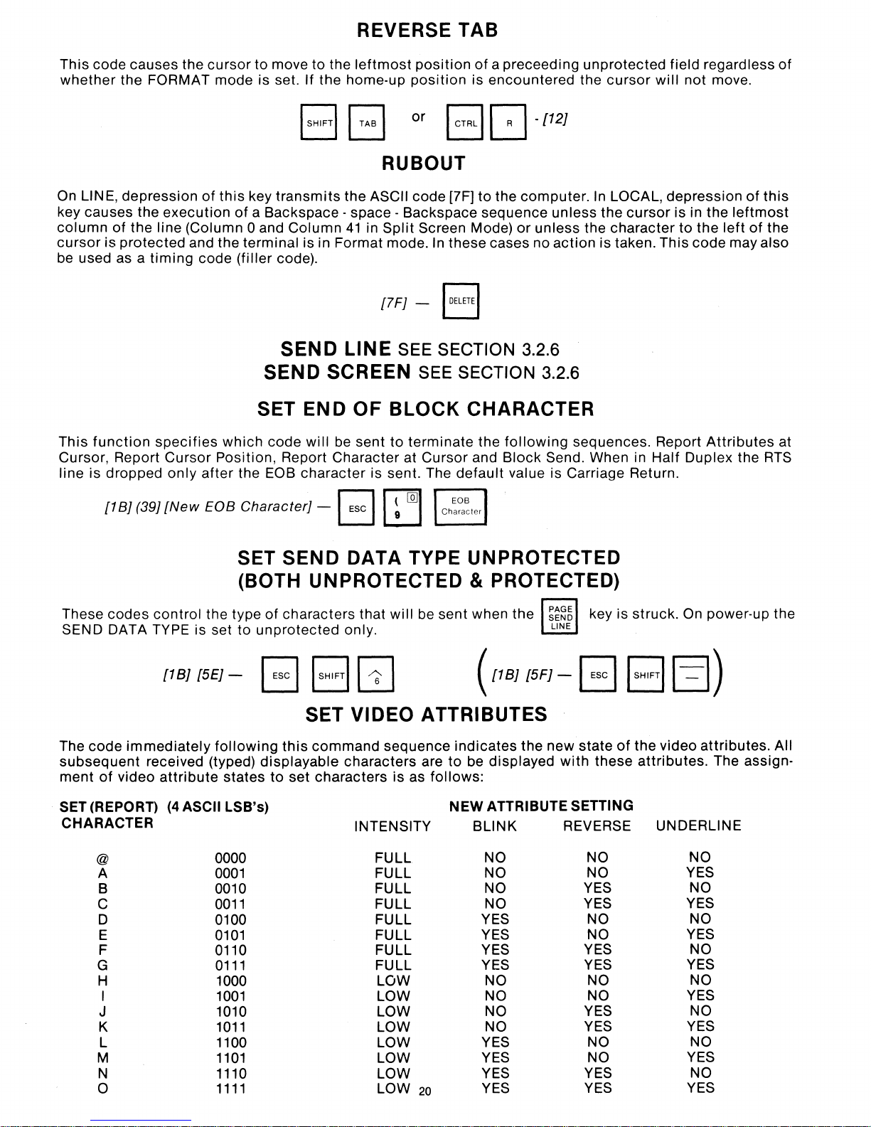
REVERSE TAB
This code causes the
whether
On
key causes the
column
cursor
be
used as a
This
Cursor, Report
line is dropped
the FORMAT mode is set. If the home-up
LINE, depression
execution
of
the line (Column 0 and
is
protected
function
and the terminal is in Format mode.
timing
specifies
Cursor
only
cursor
to move to the
leftmost
position
position
or
B
BB
RUBOUT
of
this
key
transmits
of
a Backspace - space - Backspace sequence unless the
Column
code
(filler
code).
SEND
SEND
SET
which
Position, Report Character at Cursor and
after
code
the EOB
character
the ASCII code [7F] to the computer.
41
in
Split
Screen Mode)
In
these cases no
[7FJ
- I
DELETE
LINE
SEE SECTION 3.2.6
SCREEN SEE SECTION 3.2.6
END
will
be
OF
sent
BLOCK
to
terminate the
is sent. The
of
a preceeding
is encountered the
c:J
-[12J
or
unless
action
I
CHARACTER
following
Block
default
Send. When in Half Duplex the
value is Carriage Return.
unprotected
cursor
In
LOCAL, depression
cursor
the character to the
is taken. This code may also
sequences. Report
field regardless
will
not
move.
is in the
left
Attributes
of
of
this
leftmost
of
the
at
RTS
[1
BJ
(39J
[New
EOB CharacterJ - B I
SET
SEND
(BOTH UNPROTECTED & PROTECTED)
These
SEND DATA TYPE is set to
codes
control
[1
BJ
the type
unprotected
[5EJ
- B I
of
characters that will be sent when the
SHIFTI
SET VIDEO ATTRIBUTES
The
code
immediately
subsequent
ment
of
SET (REPORT)
CHARACTER
@
A
B 0010 FULL
C
D 0100
E
F
G
H 1000 LOW
I
J 1010 LOW
K
L
M
N 1110
0
received (typed)
video
attribute
(4
following
states to set characters is as
ASCII LSB's)
this
command
displayable
0000
0001
0011
0101
0110
0111
1001
1011
1100 LOW
1101
1111
~
[Q]I
DATA TYPE UNPROTECTED
~~~6
key is struck. On power-up the
only. LINE
[2]
sequence
characters are
follows:
INTENSITY
FULL
FULL
FULL
FULL YES
FULL
FULL
FULL YES
LOW
LOW
LOW
LOW
LOW 20
(1IB1I
indicates
to
be displayed
ATTRIBUTE SETTING
NEW
BLINK REVERSE
NO NO
NO
NO
NO
YES
YES
NO
NO
NO
NO YES
YES
YES
YES
YES
5F
J-
B B
the new state
with
these
NO
YES
YES
NO NO
NO
YES
YES
NO NO
NO
YES
NO
NO
YES
YES
of
the video
attributes.
UNDERLINE
~)
attributes.
The assign-
NO
YES
NO
YES
YES
NO
YES
YES
NO
YES
NO
YES
NO
YES
All
Page 22
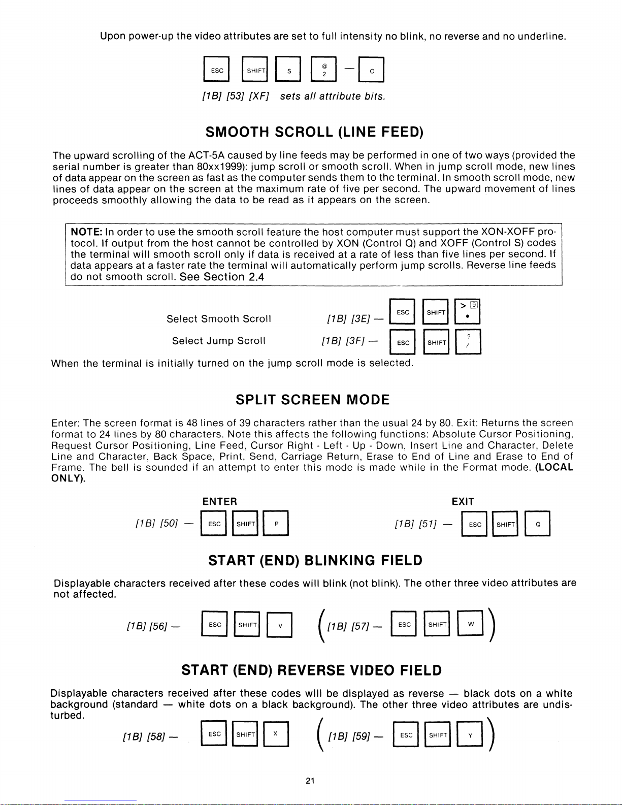
Upon power-up the video
[1B]
SMOOTH SCROLL (LINE FEED)
attributes
{53]
{XF]
are
sets
set
to
full
aI/
attribute
intensity
bits.
no
blink,
no
reverse and no underline.
The upward
serial
of
data
lines
of
proceeds
NOTE:
tocol.
the
data appears at a
do
scrolling
number
appear on the screen as fast as the
terminal
not
is greater than 80xx1999):
data appear on the screen at the
smoothly
In order
If
output
smooth
allowing
to
from the
will
smooth
faster
scroll.
of
the ACT-5A caused by line feeds may be performed in one
the data
use the
smooth
host
scroll
rate the terminal
See
Section
to
scroll
cannot
only
jump
scroll
computer
maximum
be read as
feature the
be
controlled
if
data is received at a rate
will
2.4
or
smooth
sends them
rate
of
five per second. The upward
it
appears on the screen.
host
computer
by XON (Control Q) and XOFF (Control
automatically
scroll. When in
to
the terminal.
must
of
less than five
perform
jump
r=:lr::=Jr>1m
Select
When the
Enter: The screen
format
Request
Line and Character, Back Space, Print, Send, Carriage Return, Erase to End
Frame. The bell is sounded
ONLY).
terminal
to
24
lines by 80 characters.
Cursor
is
initially
format
Positioning,
Smooth
Select
Jump
turned on the
Scroll
Scroll
SPLIT SCREEN MODE
is
48
lines
of
39
characters rather than the usual
Note
this
Line Feed, Cursor Right -
if
an
attempt
to
jump
affects
enter
{1B]
{3E]-
{1B]
{3F]-
scroll
mode is selected.
the
following
Left -Up
this
mode is made while in the Format mode. (LOCAL
~
L:J
B
24
functions:
- Down, Insert Line and Character, Delete
of
two
ways (provided the
jump
In
smooth
support
scrolls.
scroll
the
lines
mode, new
scroll
mode, new
movement
XON-XOFF pro-
per second. If
Reverse line feeds
S)
of
codes
lines
lines
L:J
ISHIFTI
IT]
by 80. Exit: Returns the screen
Absolute
of
Cursor
Line and Erase
Positioning,
to
End
of
ENTER
{1
B]
{50] - B \
START (END) BLINKING FIELD
Displayable
not
affected.
characters
{1B]
{56]-
received
START (END) REVERSE VIDEO FIELD
Displayable
background
turbed.
characters
(standard -
[1B]
{58]-
received
white
BBD
SHIFTI
[J
after
these
after
dots
on a black background). The
these
codes
codes
will
({IB][57]
will
({IB]
21
{1BJ
{51] - B
blink
(not blink). The
- B B
be displayed as reverse -
other
(59]-
B B
other
three video
EXIT
\SHIFTI
three video
GJ
)
black
dots
attributes
D)
G
attributes
on a
white
are undis-
are
Page 23
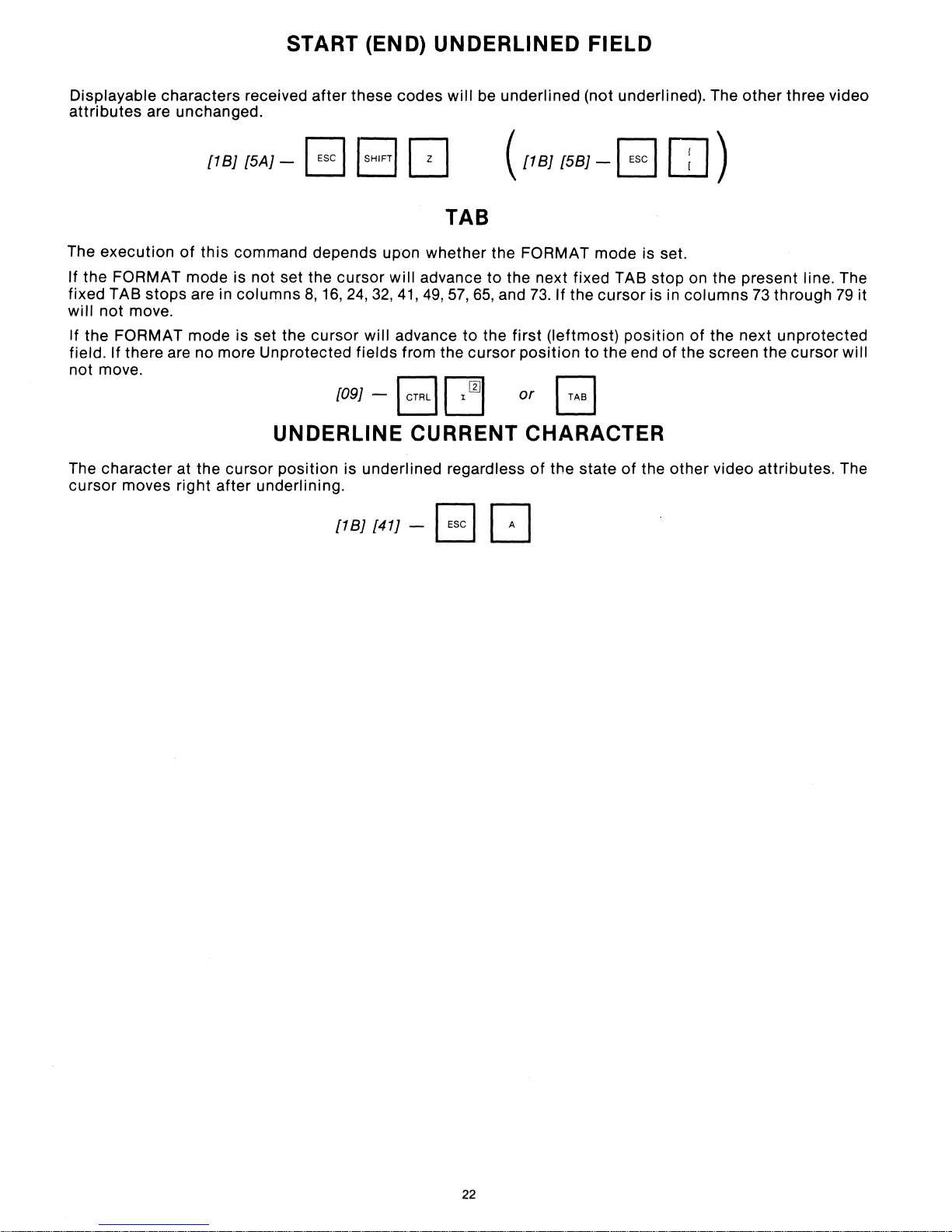
START (END)
UNDERLINED
FIELD
Displayable characters received
attributes
The
execution
If the FORMAT
fixed TAB
will
not
If the FORMAT
field. If there are no more Unprotected
not
move.
are unchanged.
[181
of
this
mode
stops
are in
move.
mode
[5A1
command depends upon
is not set the
columns
is set the
after
- B I
cursor
8,16,24,32,41,49,57,65,
cursor
[091
UNDERLINE CURRENT CHARACTER
The
character
cursor
moves
at the
right
cursor
after
underlining.
position
[181
these
codes
SHIFT/
[]
will
be underlined (not underlined). The
([IBJ
TAB
whether
will
advance
will
advance
fields
from the
- I CTRL I
is underlined regardless
[41J
c=l
- B
the FORMAT mode is set.
to
the next fixed TAB
and
to
the
first
cursor
[]
[5BJ
73.
If the
(leftmost)
position
or
of
the state
- B
cursor
to the end
is in
position
of
the
other
OJ)
stop
on the present line. The
columns
of
of
the screen the
other
73
the next
video
attributes.
through
unprotected
three video
79
it
cursor
will
The
22
Page 24
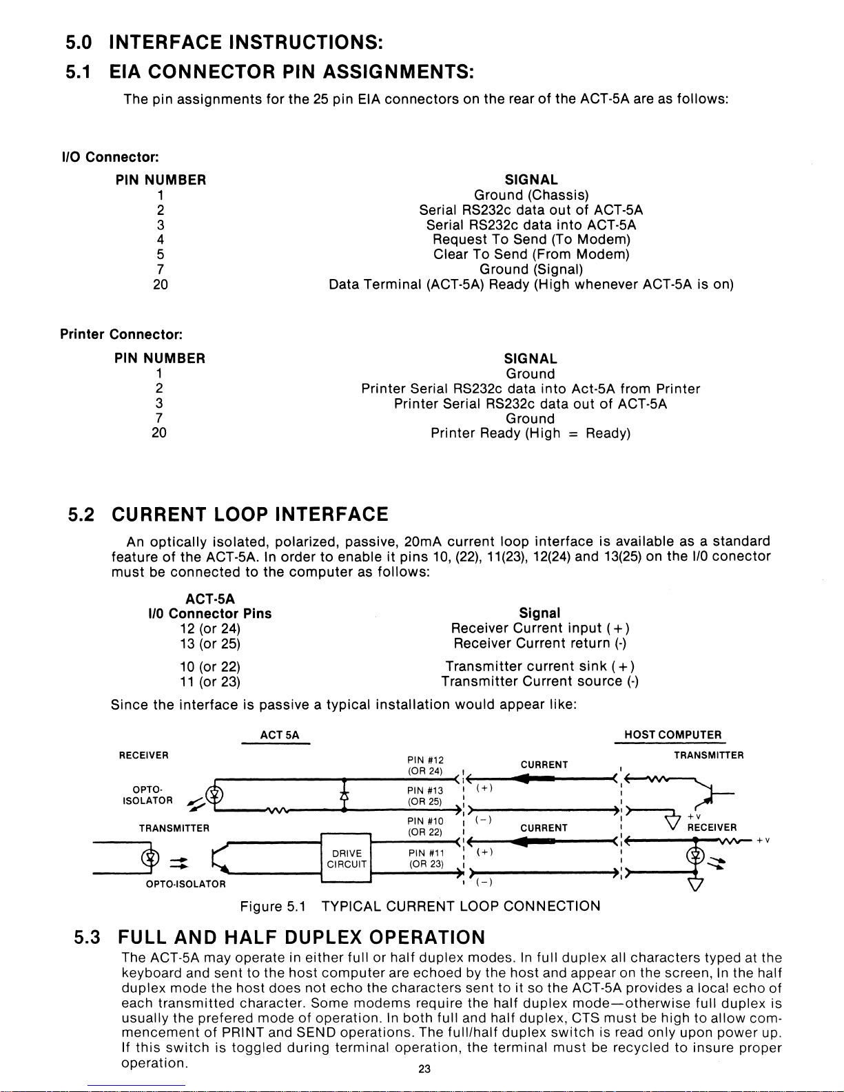
5.0 INTERFACE INSTRUCTIONS:
5.1
I/O
Connector:
Printer
EIA CONNECTOR PIN ASSIGNMENTS:
The pin
PIN NUMBER
Connector:
PIN
assignments
1
2
3
4
5
7
20
NUMBER
1
2
3
7
20
for
the
25
pin EIA
Data Terminal (ACT-5A) Ready (High whenever ACT-5A is on)
connectors
Printer
Printer
on the rear
Serial RS232c data
Serial RS232c data
Request To
Clear To Send (From Modem)
Serial RS232c data
Serial RS232c data
Printer Ready (High
of
the ACT-5A are as
SIGNAL
Ground (Chassis)
out
of
into
Send (To Modem)
Ground
(Signal)
SIGNAL
Ground
into
Ground
Act-5A from Printer
out
= Ready)
ACT-5A
ACT-5A
of
ACT-5A
follows:
5.2 CURRENT LOOP INTERFACE
An
optically
feature
must
Since
RECEIVER
of
be
connected
I/O
Connector
the
OPTO·
ISOLATOR
TRANSMITTER
~:::
OPTO·ISOLATOR
isolated, polarized, passive, 20mA
the
ACT-5A. In
ACT-SA
12
(or
24)
13
(or
25)
10
(or
22)
11
(or
23)
interface
~$
to
the
Pins
is
passive a
ACT
VV'w
Figure
order
to
enable
computer
SA
as
typical
i
DRIVE
CIRCUIT
5.1
TYPICAL CURRENT LOOP CONNECTION
follows:
installation
it
current
pins
10, (22),11(23),12(24) and 13(25) on
Receiver Current
Receiver Current return
Transmitter
Transmitter
would
PIN
#12
(OR
24)
#13
PIN
(OR
PIN #10
(OR
PIN
(OR
25)
22)
#11
23)
:\
',)
IE
' >
:
I
I(
:
I
(+)
(-)
(+)
(-)
loop
interface
Signal
input
current
Current
appear like:
CURRENT
•
CURRENT
•
sink
source
is
available as a standard
the
1/0
conector
(+)
(-)
( + )
(-)
HOST COMPUTER
,
TRANSMITTER
<,=->-
):>
I
I
<1:
):
+v
~
RECEIVER
f:H
5.3 FULL AND
The ACT-5A may operate in
keyboard and
duplex
each
usually
mencement
If
operation.
mode
transmitted
the prefered mode
this
switch
HALF
sent
to
the
the
host
does not
character. Some
of
PRINT and SEND operations. The
is
toggled
DUPLEX OPERATION
either
host
of
during
full
or
half
duplex
computer
echo
operation.
terminal operation, the terminal
are echoed by the
the characters sent to it so the ACT·5A provides a local
modems
require the half
In
both
23
modes.
full
and half duplex, CTS
full/half
In
full
duplex
host
and appear on the screen,
duplex
duplex
switch
must
all characters typed at the
mode-otherwise
must
is read only upon
be recycled
be high
to
In
the half
echo
of
full
duplex
to
allow
power
insure proper
is
com-
up.
Page 25
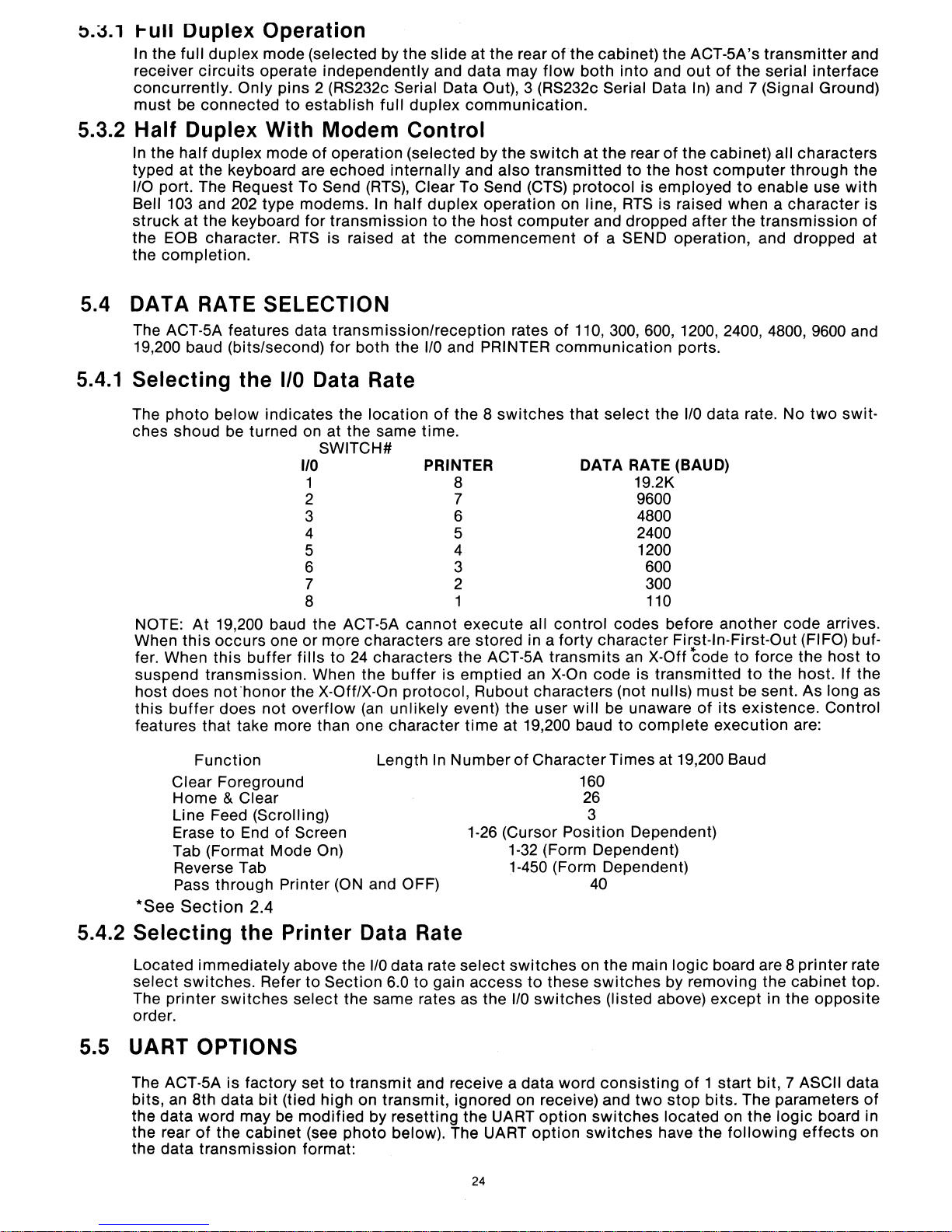
o.J.'
t-ull Duplex Operation
In
the
full duplex mode (selected by the slide
receiver
concurrently. Only pins 2 (RS232c Serial Data Out), 3 (RS232c Serial Data In) and 7 (Signal Ground)
must
circuits
be connected
operate independently and
to
establish
full
duplex
at
the rear
data
communication.
may
ofthe
flow
cabinet) the ACT-SA's
both
into
and
out
transmitter
of
the serial interface
and
5.3.2
Half
In the
typed at the keyboard are echoed internally and
1/0 port. The Request To Send
Bell 103 and 202 type modems. In
struck
the EOB character.
the
Duplex
half
duplex
at the keyboard for
completion.
With
mode
Modem
of
operation (selected by the
(RTS),
transmission
RTS
is raised at the
5.4 DATA RATE SELECTION
The ACT-SA features data transmission/reception rates
5.4.1
19,200 baud (bits/second)
Selecting
The
photo
ches shoud be turned on at the same time.
NOTE:
When
fer. When
suspend transmission. When the
host does
this
features that take more than one character
At
this
buffer
the
1/0
below indicates the
19,200 baud the ACT-SA cannot execute all
occurs
this
not'honor
does not overflow
one or more characters are stored in a forty character First-In-First-Out (FIFO) buf-
buffer
for
both the
Data Rate
location
SWITCH#
110
1
2
3
4
S
6
7
8
fills
to
24
characters the ACT-SA
the X-OfflX-On protocol, Rubout characters (not nulls)
(an
Control
also
Clear To Send (CTS)
half
duplex
to
I/O
of
PRINTER
buffer
unlikely
operation on line,
the
host
commencement
and PRINTER
the 8
switches
8
7
6
S
4
3
2
1
is emptied an
event) the user
time
at 19,200 baud
switch
transmitted
computer
at
protocol
of
of
110,300,600,1200,2400,4800,9600
communication
that select the
DATA
control
transmits
X-On
will
the rear
and dropped
a SEND operation, and dropped at
codes before another code arrives.
code
be unaware
of
the cabinet) all characters
to the
RTS
RATE
an X-Off
to
host
is employed
is raised when a
after
ports.
I/O
(BAUD)
19.2K
9600
4800
2400
1200
600
300
110
code
is
transmitted
complete
computer
to
the
data rate. No
to
must
be sent. As long as
of
its existence. Control
execution
through the
enable use
character
transmission
two
force the host to
to
the host. If the
are:
swit-
with
is
of
and
Function
Clear Foreground
Home & Clear
Line Feed (Scrolling)
Erase
Tab (Format Mode On)
to
End
of
Reverse Tab
Pass through Printer (ON and OFF)
*See Section 2.4
5.4.2
Selecting
Located
select
The
order.
immediately
switches.
printer
switches
the
Refer
Printer
5.5 UART OPTIONS
The ACT-SA is factory set
bits, an 8th data
the
data
word may be
the rear
the data
of
transmission
bit
(tied high on transmit, ignored on receive) and
the cabinet (see
Length In
Screen
Number
1-26 (Cursor Position Dependent)
Data Rate
above the
to
select the same rates as the
modified
format:
I/O
data rate
Section 6.0 to gain access
to
transmit
by resetting the UART
photo
below). The UART
select
and receive a data word
24
of
Character Times at 19,200 Baud
160
26
3
1-32
(Form Dependent)
1-450 (Form Dependent)
40
switches
to
I/O
switches
option
these
option
on
the
main
logic
switches
(listed above) except in the oppOSite
consisting
switches
switches
by removing the cabinet top.
of
1 start bit, 7 ASCII data
two
stop
bits. The parameters
located on the logic board in
have the
board are 8
following
printer
effects
rate
of
on
Page 26
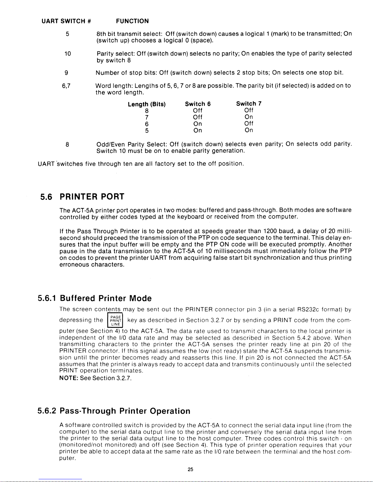
UART SWITCH # FUNCTION
UART
5
10 Parity select:
9
6,7
8 Odd/Even Parity Select:
'switches
Word
the
five
8th
bit
(switch
by
switch
Number
length:
word
Switch
through
transmit
5.6 PRINTER PORT
The ACT-5A
controlled
printer
by
either
port
select:
up)
chooses a logical
Off
(switch
8
of
stop
bits:
Lengths
length.
Length (Bits)
8
7
6
5
10
must
be on
ten are all
operates
codes
factory
typed
Off
of
in
at
Off
down)
(switch
5,
Off
to
enable
two
the
(switch
0 (space).
selects
6, 7 or
8 are
Switch 6
(switch
set
to
modes:
keyboard
down)
down)
possible.
Off
Off
On
On
down)
parity
the
off
buffered
or
causes a logical
no parity; On
selects 2 stop
selects
generation.
position.
and pass-through. Both
received from
enables
bits;
The parity
Switch 7
Off
On
Off
On
even parity; On
the
1 (mark)
the
type
On
selects
bit
(if
selected)
computer.
to
be
of
selects
modes
transmitted;
parity
one
selected
stop
bit.
is added on
odd parity.
are
software
On
to
If
the
Pass
second
sures
pause
on
erroneous
should
that
in
codes
Through
the
the
data
to
prevent
characters.
Printer
preceed
input
buffer
transmission
the
is
to
the
transmission
will
printer
5.6.1 Buffered Printer Mode
The screen
depreSSing
puter
independent
transmitting
PRINTER
sion
until
assumes
PRINT
NOTE: See
contents
the
(see
Section
connector.
the
that
operation
Section
may be sent
~~I~~
LINE
4)
to the ACT-5A. The data rate used to
of
the
I/O
characters
If
printer
the
becomes
printer
terminates.
3.2.7.
key as
data rate and may
this
described
to the
signal
is always ready
be
operated
be
empty
to
the
ACT-5A
UART
from
out
the
printer
assumes
ready and reasserts
at
speeds
of
the
PTP on
and
the
of
acquiring
PRINTER
in
Section
be
selected
the
ACT-5A senses the
the
low
to
accept
greater
code
PTP ON
10
milliseconds
false
start
connector
3.2.7 or by
as
(not ready) state the ACT-5A
this
line. If pin
data and
than
1200 baud, a
sequence
code
bit
pin 3 (in a serial RS232c format) by
sending
transmit
described
transmits
to
the
will
be
executed
must
immediately
synchronization
a PRINT
characters
in
Section
printer
ready line at pin
20
is
not
continuously
delay
terminal.
to
connected
This
promptly.
follow
and
thus
code
from the com-
the
local
5.4.2 above. When
suspends
the ACT-5A
until
the
of
20
milli-
delay
Another
the
printing
printer
20
of the
transmis-
selected
en-
PTP
is
5.6.2 Pass-Through Printer Operation
A
software
computer)
printer
the
(monitored/not
printer
puter.
controlled
to the serial data
to
the serial data
monitored)
be
able
to
accept
switch
is provided by the ACT-5A to
output
output
and
data
line
to
the
printer
line
to
the
off
(see
Section
at the same rate as the
25
host
4).
connect
and
conversely
computer.
This
type
of
I/O
rate between the
the serial data
the serial
Three
printer
codes
operation
terminal
input
data
control
requires that
and
line (from the
input
line from
this
switch
the
host
- on
your
com-
Page 27
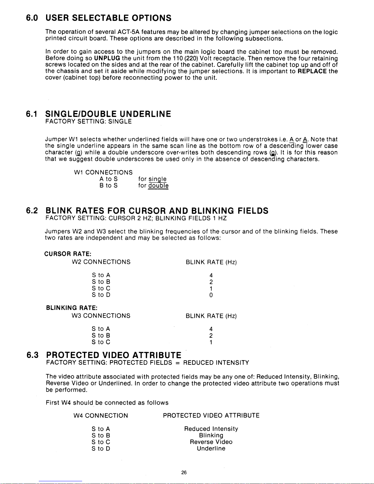
6.0 USER SELECTABLE
OPTIONS
6.1
The operation
printed
In
Before
screws
the chassis and set it aside
cover (cabinet top) before reconnecting power
circuit
order
dOing so UNPLUG the
located on the sides and at the rear
SINGLE/DOUBLE
FACTORY SETTING: SINGLE
Jumper
the
character
that we suggest
W1
single underline appears in the same scan line
of
several ACT-SA features may be altered by changing
board. These
to
gain access to the
options
jumpers
unit
from the 110
while
modifying the
are described in the
on the main logic board the cabinet top
of
UNDERLINE
selects whether underlined fields will have one or
(g)
while a double underscore over·writes both descending rows
double underscores
W1
CONNECTIONS
A to S for single
B to S for double
be
used only in the absence of descending characters.
following
(220)
Volt receptacle. Then remove the four retaining
the cabinet. Carefully
jumper
to
the unit.
selections. It is important
two
understrokes i.e. A
as
the
bottom
jumper
subsections.
lift
row of a
selections
the cabinet
descendinglower
(g).
on the logic
must
be removed.
top
up and
to
REPLACE the
or
A.
It is for this reason
off
of
Note that
case
6.2 BLINK RATES FOR CURSOR
FACTORY SETTING: CURSOR 2
Jumpers W2 and W3 select the blinking frequencies of the cursor and of the blinking fields. These
two rates are independent and may be
CURSOR RATE:
W2 CONNECTIONS
S to A
S to B
S to C
to D
S
BLINKING
RATE:
W3
CONNECTIONS
S to A
S to B
S
to
C
HZ;
AND
BLINKING FIELDS 1 HZ
selected as follows:
6.3 PROTECTED VIDEO ATTRIBUTE
FACTORY SETTING: PROTECTED FIELDS = REDUCED INTENSITY
The video
Reverse Video
be
performed.
attribute
or
associated
Underlined.
with
protected fields may be
In
order
to
change the protected video attribute two operations must
BLINKING
BLINK RATE (Hz)
4
2
1
o
BLINK RATE (Hz)
4
2
1
anyone
FIELDS
of: Reduced Intensity, Blinking,
First
W4
should be connected as
W4
CONNECTION PROTECTED VIDEO ATTRIBUTE
S
to
A
S
to
B
S
to
C
S
to
D
follows
Reduced
Blinking
Reverse Video
Underline
26
Intensity
Page 28
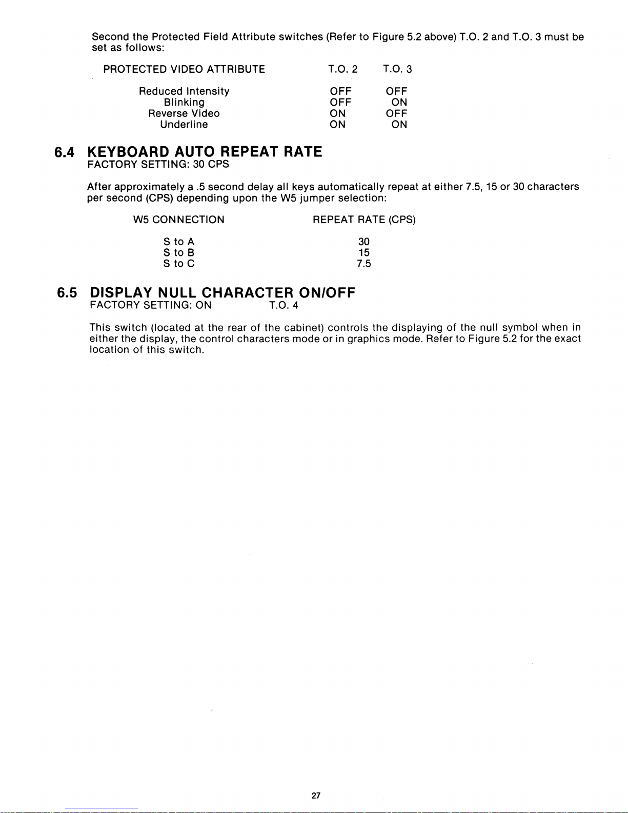
Second
set as
the
Protected Field
follows:
Attribute
switches
(Refer
to
Figure 5.2 above) T.O. 2 and T.O. 3
must
be
PROTECTED VIDEO ATTRIBUTE
Reduced
Reverse Video
Intensity
Blinking
Underline
6.4 KEYBOARD AUTO REPEAT RATE
FACTORY
After
per second (CPS) depending upon
6.5 DISPLAY NULL CHARACTER
FACTORY SETTING: ON
This
either
location
SETIING:
approximately
W5 CONNECTION
S
to
S
to
S
to
switch
(located at the rear
the display, the
of
this
switch.
30 CPS
a.5
second delay all keys
the
A
B
C
of
the
control
characters mode
W5
T.O.4
cabinet)
jumper
REPEAT RATE (CPS)
ON/OFF
T.O.2
OFF
OFF
ON
ON
automatically
selection:
controls
or
in graphics mode. Refer
T.O.3
OFF
ON
OFF
ON
repeat at
30
15
7.5
the displaying
either
of
to
7.5,15
the
Figure 5.2 for the exact
or
30 characters
null symbol when in
27
Page 29
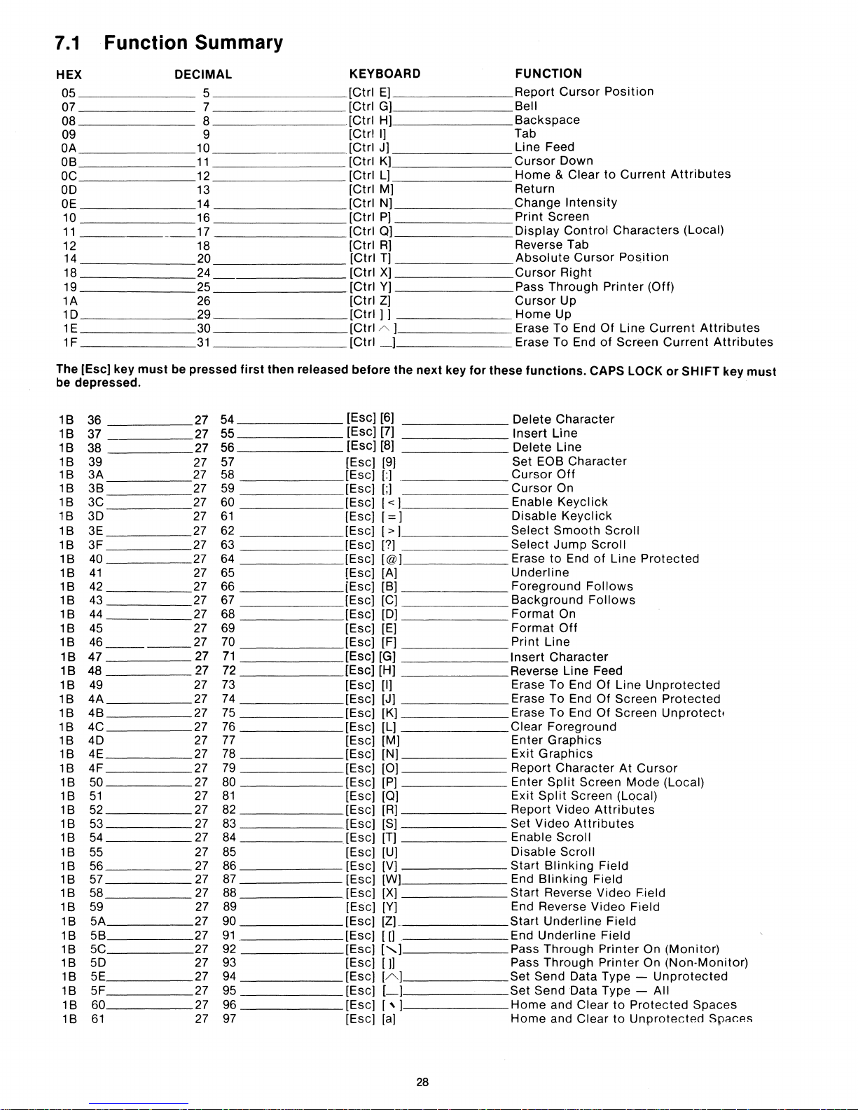
7.1
Function Summary
must
DECIMAL
5
10
11
12
13
14
16
17
18
20
24
29
30
31
be
pressed
27
27
27
27
27
27
27
27
27
27 67 [Esc] [C]
27
27
27
27
27
27
27
27
27
27
27
27
27
27
27
27
27
27
27
27
27
27
27
27
27
27
27
first
then
54
55
56
57 [Esc] [9]
58
59
60 [Esc]
61
62
63 [Esc] [?]
64 [Esc] [@] Erase
65
66
68 [Esc] [D]
69 [Esc] [E]
70 [Esc] [F]
71
72
73
74
75
76
77 [Esc] [M]
78
79
80 [Esc] [PI
81
82 [Esc] [R]
83 [Esc]
84
85 [Esc]
86 [Esc] [V]
87
88 [Esc] [X]
89
91
92 [Esc]
93 [Esc]
94 [Esc]
95
97
HEX
05
07 7
08 8
09 9
OA
08
OC
OD
OE
10
11
12
14
18
19 25
1A 26
1D
1E
1F
The [Esc] key
be
depressed.
18
36 27
18
37 27
18
38 27
18
39
18
3A 27
18
38
18
3C
18
3D
18
3E
3F
18
18
40
41
18
18
42
18
43
18
44
------
45
18
18
46
18
47
18
48
18
49
4A 27
18
48
18
18
4C
4D
18
18
4E
18
4F
18
50
51
18
18
52
18
53
18
54
18
55
18
56
18
57
18
58
18
59
18
5A 27 90 [Esc]
18
58
18
5C
18
5D
5E
18
5F
18
18
60 27 96
61
18
released
KEYBOARD
[Ctrl
E]
[Ctrl G]
.[Ctrl H]
[Ctrl
I]
[Ctrl J]
[CtrIK]
[Ctrl
L]
[Ctrl
M]
[Ctrl
N]
[Ctrl
P]
[CtrIO]
[Ctrl
R]
[Ctrl
T]
[Ctrl
X]
[Ctrl
Y]
[Ctrl
Z]
[Ctrl]]
[Ctrl
A]
[Ctrl
_]
before
[Esc] [6]
[Esc] [7]
[Esc] [8]
[Esc]
[Esc]
[:]
[;]
the
next
key
for
1<]
[Esc]
[=]
[Esc]
[>]
[Esc] [A]
[8]
[Esc]
[Esc] [G]
[Esc] [H]
[Esc] [I] Erase To End
[Esc] [J] Erase To End Of Screen
[Esc] [K] Erase To End
[Esc] [L]
[Esc] [N]
[Esc]
[0]
[Esc]
[0]
[S]
[Esc]
[T]
[U]
[Esc] [WI
[Esc] [Y]
[Zl
[Esc]
[[]
[,,]
[Jl
[A]
[Esc]
[_I
[Esc]
[,]
[Esc]
[a]
FUNCTION
Report
8ell
8ackspace
Tab
Line Feed
Cursor
Home
Return
Change
Print
Display
Reverse Tab
Absolute
Cursor
Pass
Cursor
Home
Erase To End
Erase To End
these
Delete
Insert
Delete Line
Set
Cursor
Cursor
Enable
Disable
Select
Select
Underline
Foreground
8ackground
Format
Format
Print
Insert
Reverse
Clear
Enter
Exit
Report
Enter
Exit
Report
Set
Enable
Disable
Start
End 81inking Field
Start
End
Start
End
Pass
Pass
Set Send Data Type Set Send
Home
Home
Cursor
Down
& Clear
Intensity
Screen
Control
Cursor
Right
Through
Up
Up
functions.
Character
Line
E08
Character
Off
On
Keyclick
Keyclick
Smooth
Jump
to
End
On
Off
Line
Character
Line
Foreground
Graphics
Graphics
Character
Split
Screen
Split
Screen (Local)
Video
Video
Attributes
Scroll
Scroll
81inking Field
Reverse
Reverse
Underline
Underline
Through
Through
Data
and
Clear
and
Clear
Follows
Position
to
Current
Characters
POsition
Printer
Of
of
CAPS LOCK
Scroll
Scroll
of
Follows
Feed
Of
Of
Attributes
Video
Video
Field
Printer
Printer
Type -
(Off)
Line
Screen
Line
Protected
Line
Unprotected
Screen
At
Cursor
Mode
Field
Field
Field
On
On
to
Protected
to
Unprotected
Attributes
(Local)
Current
Unprotected
All
Attributes
Current
or
SHIFT
Protected
Unprotect.
(Local)
(Monitor)
(Non-Monitor)
Spaces
Sp.Rr.es
Attributes
key
must
28
Page 30
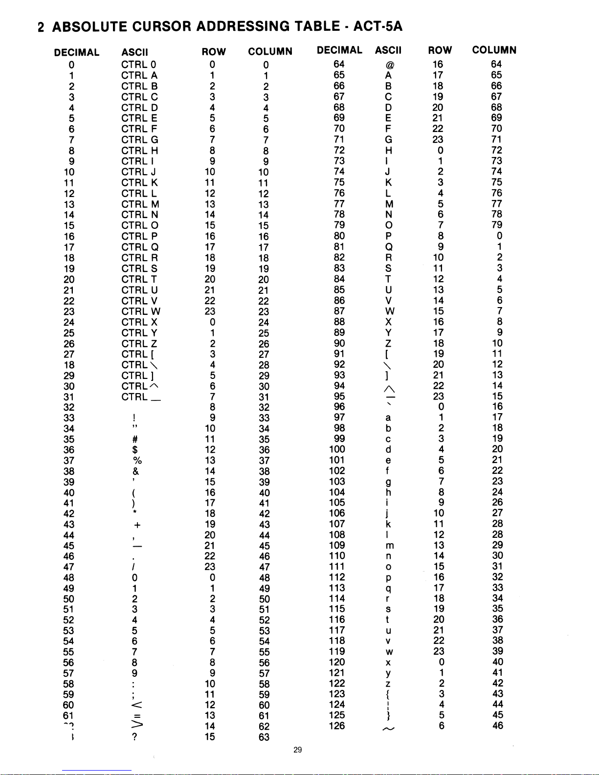
2 ABSOLUTE CURSOR
ADDRESSING
TABLE - ACT-SA
DECIMAL ASCII
0
1
2
3
4
5
6
7
8
9
10
11
12
13
14
15
16
17
18
19
20
21
22
23
24
25
26
27
18
29
30
31
CTRLO
CTRLA
CTRL B 2
CTRLC
CTRL D 4
CTRL E 5
CTRL F 6
CTRLG
CTRL H 8
CTRLI
CTRL J
CTRL K
CTRL L
CTRL M
CTRL N
CTRLO
CTRL P
CTRL a
CTRL R
CTRLS
CTRL T
CTRL U
CTRLV
CTRLW
CTRLX
CTRL Y
CTRLZ
CTRL[
CTRL"
CTRL)
CTRLA
CTRL_
32
(
)
"
#
$
&
,
!
%
*
+
33
34
35
36
37
38
39
40
41
42
43
44
45
46
47
48
49
50
51
52
53
54
55
56
57
I
0
1 1
2
3
4
5
6
7
8
9
58
59
60
61
-"')
,
<
=
>
?
ROW
0
1
3
7
9
10
11
12
13
14
15
16
17
18
19
20
21
22
23
0
1
2
3
4
5
6
7
8
9
10
11
12
13
14
15
16
17
18
19
20
21
22
23
0
2
3
4
5
6
7
8
9
10
11
12
13
14
15
COLUMN
0
1
2
3
4
5
6
7
8
9
10
11
12
13
14
15
16
17
18
19
20
21
22
23
24
25
26
27
28
29
30
31
32
33
34
35
36
37
38
39
40
41
42
43
44
45
46
47
48
49
50
51
52
53
54
55
56
57
58
59
60
61
62
63
29
DECIMAL
64
65
66
67
68
69
70
71
72
73
74
75
76
77
78
79
80
81
82
83
84
85
86
87
88
89
90
91
92
93
94
95
96
97
98
99
100
101
102
103
104
105
106
107
108
109
110
111
112
113
114 r
115
116
117
118 v
119
120
121
122
123
124
125
126
ASCII ROW
@
A
B
C
D
E
F
G
H 0
I
J
K 3
L
M 5
N 6
0
P
a
R
S
T
U
V
W
X
Y
Z
[
16
17
18
19
20
21
22
23
1
2
4
7
8
9
10
11
12
13
14
15
16
17
18
19
20
)
"
A
"
a
b
21
22
23
0
1
2
c 3
d
e
f 6
9
h 8
i 9
1
k
I
m
n
0
P
q
4
5
7
10
11
12
13
14
15
16
17
18
s
t
u
19
20
21
22
w
x
Y
z
{ 3
I
I
}
"....."
23
0
1
2
4
5
6
COLUMN
64
65
66
67
68
69
70
71
72
73
74
75
76
77
78
79
0
1
2
3
4
5
6
7
8
9
10
11
12
13
14
15
16
17
18
19
20
21
22
23
24
26
27
28
28
29
30
31
32
33
34
35
36
37
38
39
40
41
42
43
44
45
46
Page 31
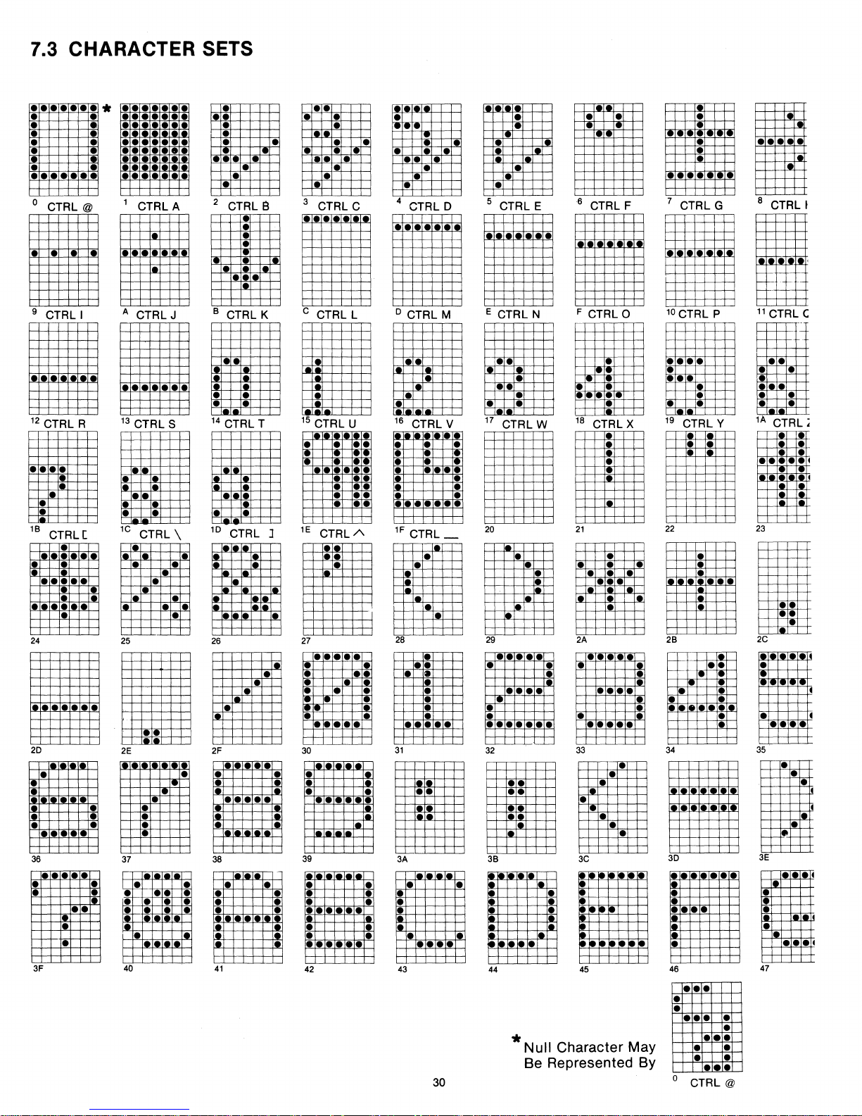
7.3 CHARACTER SETS
•••
••
••
• •
• • •
•
• •
I.
I.
•
•• ••
o CTRL @
9
CTRLI
*
•
• •
•••
1 CTRL A
•
A CTRL J 8 CTRL K
•
•
•
• •
•
•
•
•
2 CTRL a 3 CTRL C 4 CTRL D 5 CTRL E
•
• •
•
•
••
••
12 CTRL R
••
••
I.
•
18
CTRL [
•
I.
•
•
•••
••
•
I.
• • •
24 25
•
13 CTRL S
••
•
•
•
1C CTRL \
•
•
• • • • •
•
•
•
•
•
•
14 CTRL T
I.
i.
10
.CTRL
•
26
I.
] 1E
I.
•
•
••
••
20
2E
•
•
• •
•
•••
•
••
•
37 38
•
• • •
• •
36
•
•
• • •
Ie.
•
•
• •
•
• • •
~
.
•
2F
•••
•
• •
• • •
•••
••
•
•
•
•
•
•
•
3F
40
41
••
•
•
I.
•
Ie
•
•
I.
•
C CTRL L
•
•
•
•
•
• •
•
• •
•
•
••
•••
••
o CTRL M
••
• •
15 CTRL U
• •
•••
• •
•
•
•
CTRLA
•
•
27
••
•••
•
•
Ie
•
• •
•
• • •
••
••
30
•
••
••
39
•
•
•
• •
•••
•
• 1
••
••
42 43
16 CTRL V 17 CTRL W 18 CTRL X
••
••
••
••
•
•
•
• •
••
1F
CTRL_
•
•
•
••
•
••
•
•
•••
•
i
28
•
••
• •
•
•
•
•
•
•
•
•
•••
••
31
••
3A
I.
• •
•
•
•
••
• •
30
•
•
•
•
•• ••
E CTRL N
••
•
•
•
• •
20
• •
• •
,.
29
••
•••
•
• •
32
38
44
I.
•
••
••
•••
••
•
•
*
Null
Character May
Be Represented By
Tiii
• •
•
•
•
•••
6 CTRL F 7 CTRL G
F CTRL 0
•
•
••
•••
10 CTRL P
••
••
••
•
• • •
I.
19 CTRL Y
•
•
21
•
2A
•• • ••
•
• •
•
••
33
•
••
••
•••
22 23
• •
28
I.
•
• •
~
•
••
34
•
•
I-
••
•
•
•
•
3C
45
30
•
•
••
Ii:
46
•
•
o
• •
•••
••
•••
•••
•••
•
•••
CTRL@
•
••
I •
I- I-
Ie
•
•
.1
.
•
•
•
•
•
•
•••
••
8 CTRL I
j--
11
CTRL C
• •
•
• •
•
1A
CTRL,
•
•
• 4
••
••
••
••
2C
1.le
lelele
•
•
•
••
35
•
•
•
II
3E
•••
•
•
•
••
47
4
I
I
•
••
Page 32
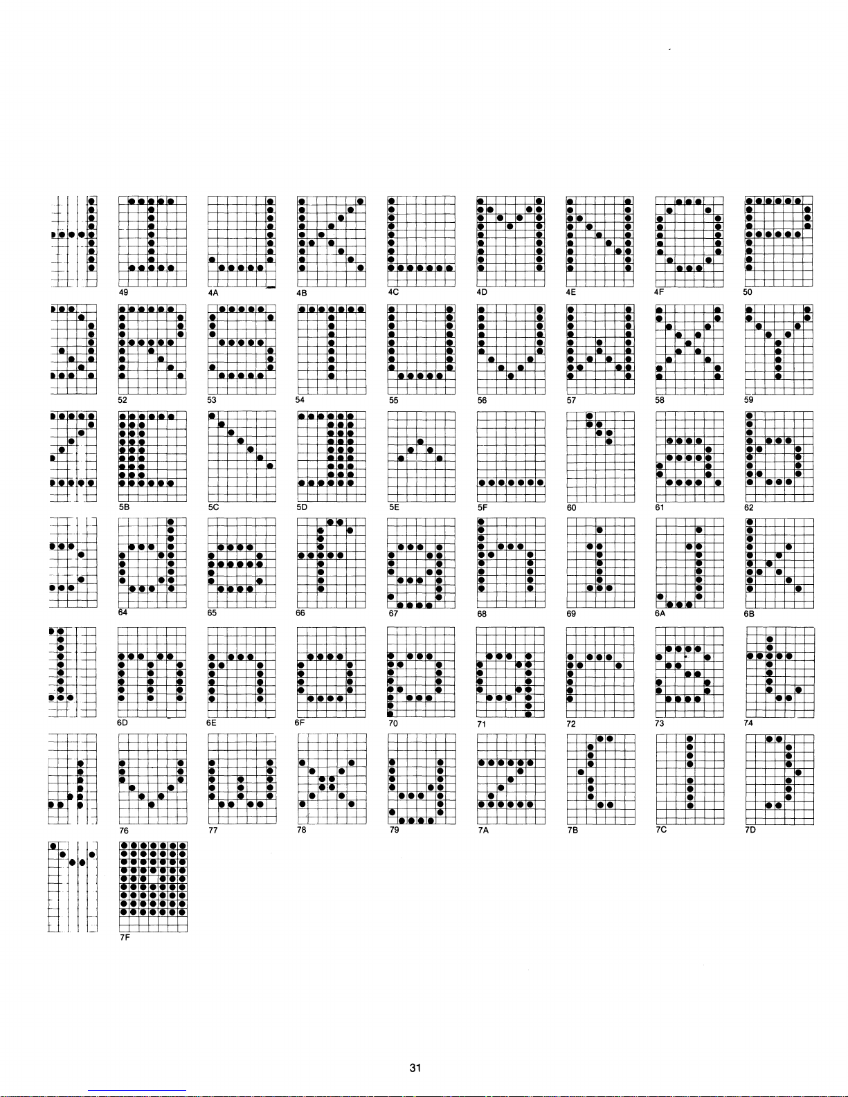
,e
•
•
•
• •
••
•
•
•
•
•
e.
ele
,e
•
-
-
-
'-!It
-
-
•
-
c-
n::
•
•
.-
. -
-i
~
•
'e
•
,-
,e
49
52
Ie
•
•
,e
,e
Ie
Ie
Ie
Ie
58
64
60
76
Ie
•
••
Ie
,e
•
••
•
•
••
Ie
4A
• •
53
5C
65
,e
••
6E
77
,e
Ie
•
,e
,e
•
48
54
'-
50
66
6F
Ie
• •
• •
,e
78
I.
,e
,e
,-
Ie
ie
Ie
Ie
•
•
•
•
• •
4C
55
5E
67
70
•
•••
79
••
•
•••
,e
•
•
•
•
•
•
•
40
56
••
••
5F
• •
••
•
68
71
,e
•
• •
••
••
••
7A
4E
57
••
60
•
~
• •
• •
,e
69
•
••
72
78
•
•••
•
•
e
•
•
••
••
••
4F
58
• •
•
••
•
61
•
6A
73
•
•
•
7C
50
,-
I.
59
•
•
••
•
62
•
••
•
68
7.4
70
•
•••
•••
•
•
•
•
Ie
•
•
•
•
•
•
• •
..
-
7F
31
Page 33
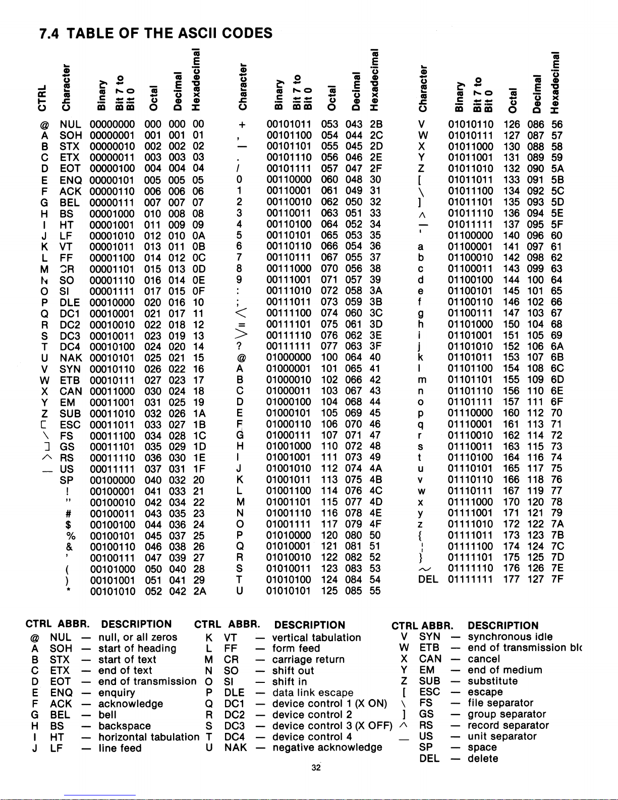
7.4 TABLE OF THE ASCII CODES
..
CD
U
-
~
t!
II:
as
...
s:.
(.)
(.)
@
NUL 00000000
SOH
A
STX 00000010
B
ETX
C
EOT
D
ENQ
E
ACK 00000110
F
BEL
G
BS
H
I HT
LF
J
VT
K
L FF 00001100
~R
M
f'.4
SO
SI
0
P DLE
Q
DC1
R
DC2
DC3
S
T
DC4
NAK
U
SYN
V
ETB
W
X CAN 00011000
Y
EM
SUB 00011010
Z
[
ESC
\
FS
]
GS
A
RS
-
US
SP
I
"
#
$
%
& 00100110
( 00101000
)
*
0
~
-
1'0
as
c
--
iii iii iii
00000001
00000011
00000100
00000101
00000111
00001000
00001001
00001010
00001011
00001101
00001110
00001111
00010000
00010001
00010010
00010011
00010100
00010101
00010110
00010111
00011001
00011011
00011100
00011101
00011110
00011111
00100000
00100001
00100010
00100011
00100100
00100101
00100111
00101001
00101010
'ii
E
'ii
()
u
CD
-
C
0
000
000
001 001
002 002
003 003
004 004
005
005
006
006
007 007
010
008
011
009
012
010
013
011
014
012
015 013
016 014
017 015
020 016
021
017
022
018
023
019
024 020
025
021
026
022
027 023
030 024
031
025
032 026
033 027
034 028
035 029
036 030
037
031
040
032
041
033
042
034
043
035
044
036
045 037
046 038
047
039
050
040
051
041
052
042
'ii
E
()
CD
'g
as
><
CD
::E:
00
01
02
03 00101110
04
05
06
07
08
09
OA
OB
OC
OD
OE
OF
10
11
12
13
14
15
16
17
18
19
1A
1B
1C
1D
1E
1F
20
21
22
23
24
25
26
27
28
29
2A
..
CD
U
-
t!
as
s:.
(.)
+
I
0
1
2 00110010
3
4 00110100
5
6 00110110 066
7
8 00111000 070
9
,
<
>
?
@
A
a
C
D
e
0
~
-
1'0
as
c
--
iii
iii iii
00101011
00101100
00101101
00101111
00110000
00110001
00110011
00110101
00110111
00111001
00111010
00111011
00111100
00111101
00111110
00111111
01000000 100
01000001
01000010
01000011
01000100
01000101
R 01000110
G
01000111
H 01001000 110
I
01001001
01001010
J
01001011
K
L 01001100
01001101
M
N 01001110
01001111
0
P 01010000
01010001
Q
01010010 122
R
S
01010011
T 01010100
01010101
U
'ii
E
'ii
()
u
CD
-
C
0
053
043
054
044
045
055
046
056
057
047
060
048
061
049
062
050
051
063
064
052
065
053
054
067
055
056
071
057
072 058
073 059
074
060
075
061
076 062
077
063
064
101
065
102
066
103
067
104
068
105
069
106
070
107
071
072
111
073
112
074
113
075
114
076
115
077
116
078
117
079
120
080
121
081
082
123
083
124
084
125
085
'ii
E
()
CD
'a
as
><
CD
::E:
2B
2C
2D
2E
2F Z 01011010
30
31
32
33
34
35
36
37
38
39
3A
3B
3C
3D
3E
3F j
40
41
42
43
44
45
46
47
48
49
4A
4B
4C
4D
4E
4F
50
51
52
53
54
55
..
CD
U
-
t!
as
s:.
(.)
V 01010110
W
X 01011000
Y
[
\
]
/\
a
b
c
d
e
f 01100110
g
h 01101000
i
k
I 01101100
m
n 01101110
0
P
q
r
s
t
u
v 01110110
w
x
Y
z
{
I
I
}
""'-"
DEL
~
S
C
__
as
I'
°
iii iii iii
01010111
01011001
01011011
01011100
01011101
01011110
01011111
01100000
01100001
01100010
01100011
01100100
01100101
01100111
01101001
01101010
01101011
01101101
01101111
01110000
01110001
01110010
01110011
01110100
01110101
01110111
01111000
01111001
01111010
01111011
01111100
01111101
01111110
01111111
'ii
E
'ii
()
u
CD
-
0
C
126
086
127
087
130
088
131
089
132
090
133
091
134
092
135
093
136
094
137
095
140
096
141
097
142
098
143
099
144
100
145
101
146 102
147
103
150 104
151
105
152 106
153 107
154 108
155 109
156 110
157
111
160 112
161
113
162 114
163
115
164 116
165 117
166 118
167 119
170 120
171 121
172
122
173 123
174 124
175 125
126
176
177 127
'ii
E
()
CD
'g
as
><
CD
l:
56
57
58
59
5A
5B
5C
5D
5E
5F
60
61
62
63
64
65
66
67
68
69
6A
6B
6C
6D
6E
6F
70
71
72
73
74
75
76
77
78
79
7A
7B
7C
7D
7E
7F
CTRL
ABBR.
@
NUL
SOH
A
STX
B
ETX
C
EOT
D
ENQ enquiry P DLE
E
ACK acknowledge Q
F
BEL
G
BS
H
I HT
J LF
DESCRIPTION
null,
or
all zeros
start
of
heading
start
of
text
end
of
text
end
of
transmission
bell
backspace
horizontal tabulation T
line feed
CTRL ABBR.
K VT
L FF
M
N
0
R
S
U
CR
SO
SI
DC1
DC2
DC3
DC4
NAK
DESCRIPTION
-
vertical tabulation
form feed
- carriage return
shift
out
shift
in
link escape
data
device control 1
device control 2
device control 3
device control 4
negative
acknowledge
32
(X
(X
CTRLABBR.
V
W
X
Y
Z SUB
ON)
OFF)
\
/\
SYN
ETB
CAN cancel
EM
[
ESC
FS
]
GS
RS
US
SP
DEL
DESCRIPTION
synchronous idle
end
of
transmission
end
of
medium
substitute
escape
file separator
group separator
record separator
unit
separator
space
delete
blc
Page 34
8.0 WARRANTY AND SERVICE INFORMATION
a)
The ACT-5A requires no maintenance and should perform faithfully for many years. MICRO-TERM
will
repair any unit which fails within the original warranty period provided that no modifications
have been performed on the circuit, other than the jumper modifications
b)
The ACT-5A is accompanied by a limited one year warranty. For in-warranty service, the user may
elect
to
return either the defective board
TERM
and freight
it
c)
Beyond the warranty period MICRO-TERM will charge a nominal fee for the repair
complete technical manual including s.chematic, theory
available
of your ACT-5A can
will return in-warranty repairs freight prepaid for the first ninety days
collect thereafter. The video display module is
is warranted by its manufacturer for ninety days and likewise by MICRO-TERM, Inc.
to
owners of the ACT-5A. Any further information relating to the operation
be
obtained by writing directly to: TECHNICAL STAFF
or
the entire
unit
MICRO-TERM,INC.
1314
St. Louis, Missouri 63144
314-968-8151
9.0 CUSTOM MODIFICATIONS
MICRO-TERM is one of the few computer terminal manufacturers that will modify its standard terminals
to
exact customer specifications--even for quantity one. Write for information.
outlined in this manual.
to
the factory, freight prepaid. MICRO-
of
the warranty period
an
exception
of
operation and timing diagrams is
Hanley Industrial Ct.
to
this
one year warranty;
of
any ACT-5A. A
or
interfacing
33
Page 35

NOTES
Page 36

,10.0 SUGGESTION SHEET
MICRO-TERM, Inc. maintains a
I
I Please
publications.
comment
To
do
this
effectively we need user feedback--your critical evaluation
on this manual's completeness, accuracy, organization, usability and readability.
I
I
,
I
I Did you find errors in this manual?
I
I
I
I How can
I
this
manual be improved?
continuous
______________________
______________________
effort
to
improve the
quality
and usefulness
of
this
manual.
of
its
_
_
: I
,
I
I
I
I
I
I
I
I
I
I
I
Please describe your
Name
_________________
Street
City
PLEASE SEN D TO:
__________
__________________
position
---,-
______
Organization
Department
State
_______
MICRO-TERM, INC.
1314 HANLEY INDUSTRIAL COURT
ST.
LOUIS, MO. 63144
ATTENTION: TECHNICAL PUBLICATIONS STAFF
___________
Zip
____
_
_
I
I
35
Page 37

Page 38

 Loading...