


MICROTEL D51T
Microtel D51T
Operating Manual
14 September 2009
Rev. A
Proprietary Notice: This document and the subject matter hereto are the
property of MICROTEL, Inc. and shall not be reproduced or copied or used for the
purpose of manufacturing or sale of apparatus, except by written permission of
MICROTEL.
MICROTEL
11725 Sunbelt Court
Suite C
Baton Rouge, LA 70809
225-303-0436
Fax: 225-303-0568
www.microtel-inc.com

MICROTEL D51T
Record of Changes
Rev. Date Description of Changes By
- 9/14/ 09 Original Release AEF
ii

TABLE OF CONTENTS
INTRODUCTION 2
CHAPTER 1 - DESCRIPTION OF THE D51T DIALER 4
CHAPTER 2 - INSTALLATION 8
Quick Start Procedure 11
CHAPTER 3 - OPERATION 13
Configuration 14
Basic System Information 14
Configuring Fault Inputs 16
Telephone Numbers 18
MICROTEL D51T
Operations 18
Alarm Acknowledgment 19
Checking System Status 19
Controlling the local output relay 20
CHAPTER 4 - MAINTENANCE/TROUBLESHOOTING 21
CHAPTER 5 - ADVANCED TOPICS 23
Advanced Configuration Options 23
APPENDICES 25
APPENDIX A: Technical Specifications 25
APPENDIX B: Glossary of Dialer Terminology 28
APPENDIX C: FCC Requirements 29
APPENDIX D: D51T Command Summary 30
APPENDIX E: Mechanical Dimensions 31
LIST OF ILLUSTRATIONS
Figure 1: Controls and Indicators................................................................................3
Figure 2: Power Supply Connection ...........................................................................8
Figure 3: I/O Terminal Connections ...........................................................................10
Figure 4: Mounting dimensions ..................................................................................30
1

INTRODUCTION
hank you for choosing the Microtel D51T Dialer to implement your remote digital
and temperature alarm monitoring solution. You have chosen a product that is
T
The Microtel D51T features a single level, interactive command structure--there are no
multi-level menu structures to navigate. Commands are sent to the dialer through your
telephone either locally or during a call to or from the dialer, by pressing a sequence of
touch-tones on your telephone. Each command entered is acknowledged with a spoken
response from D51T, providing verification that the command was entered correctly and
understood by the dialer.
About this Manual: This manual is organized with the most crucial information in
the front; more advanced topics are saved for last or included in the appendices.
Who Should Read this Manual: Anyone involved with use of the dialer should
read the General Description and Operation chapters of the manual. The Operation
chapter in particular should be read by any personnel who may be required to respond to
alarm calls from the dialer. The additional chapters can be read at a later time, or when
necessary by authorized personnel to maintain the dialer or troubleshoot any problems
you might encounter. System administrators should read the Advanced Topics chapter
for information on the use of the dialer’s remote software configuration capabilities.
In a Hurry to Setup? Read the Quick Start section of the Installation chapter.
If you encounter a difficulty that cannot be resolved using the information in the manual,
call MICROTEL at (225) 303-0436.
Again, thank you for choosing MICROTEL.
simple to set up and easy to use. D51T has been designed and manufactured to
operate with minimal operator intervention.
MICROTEL D51T
2
MICROTEL D51T
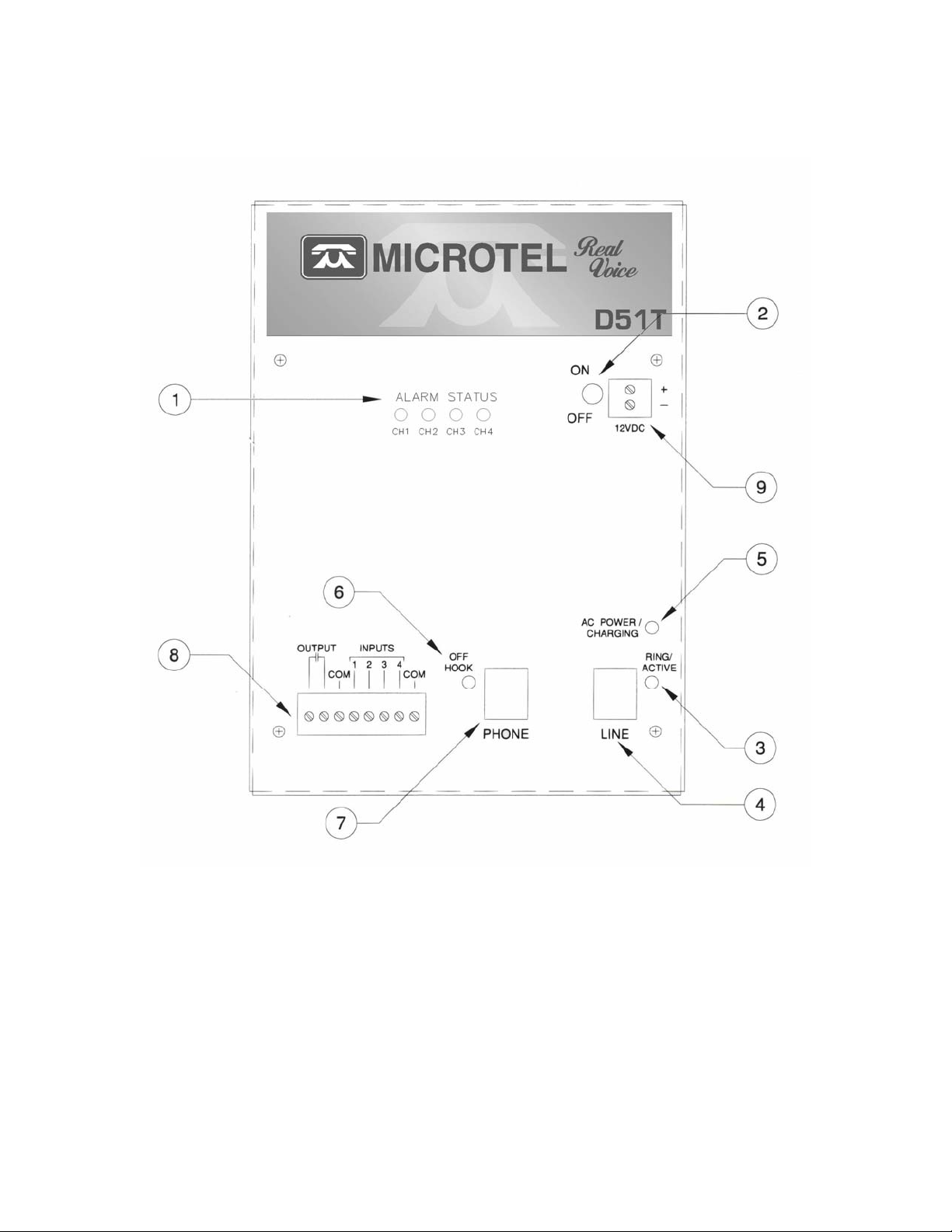
Figure 1: Controls and Indicators
3

MICROTEL D51T
CHAPTER 1 - Description of the D51T Dialer
he D51T is a small, rugged, and simple, but powerful, device which easily handles
complex dialing notification and alarm monitoring. To accomplish these tasks,
T
(1) FAULT LEDS in the upper middle indicate status for each of the four input channels:
GREEN (Steady) = Normal.
GREEN (Flashing) = Input returned to normal state, but is not yet acknowledged.
YELLOW = Input is in fault state, but alarm delay has not yet elapsed.
RED (Flashing) = Input is in unacknowledged alarm state.
RED (Steady) = Input is in acknowledged alarm state.
(2) ON/OFF SWITCH located in the upper right corner, turns the dialer on or off.
(3) RING/ACTIVE LED located adjacent to the LINE connector indicates call progress
(4) LINE JACK is a standard RJ11 phone jack where an outside line is connected to the
(5) AC POWER/CHARGING LED indicates that external power is present and is
(6) OFF HOOK LED located adjacent to the PHONE connector is turned on whenever
(7) PHONE JACK is a standard RJ11 phone jack used to connect a local phone--used
(8) I/O TERMINAL BLOCK is used to wire external sensors to the dialer, and also
(9) 12 VDC TERMINAL BLOCK for connecting 12 – 20 VDC Power.
D51T has an equally simple operator interface. Figure 1 illustrates the controls
and indicators of the dialer, and the following paragraphs describe them.
while the dialer is off-hook and incoming ring detection when on-hook.
dialer.
charging the internal, standby battery
the dialer senses that a telephone connected to the phone jack is off-hook, and D51T
is ready to accept programming commands.
for entering programming commands--to the dialer.
provides the local alarm contacts to external equipment.
4

MICROTEL D51T
How Does the Dialer Work? This section provides a simple theory of operation by
asking a few questions about typical use of the dialer. The following paragraphs assume
the dialer is hooked up and running as described in the Installation chapter. The
Operation chapter provides the details that are missing from the discussion below.
What Happens when an Alarm Occurs? D51T has a telephone directory of up
to four people, answering machines, or pagers to call in the event of an alarm. When an
alarm occurs, the dialer begins to place a series of telephone calls in an attempt to have
someone acknowledge the alarm.
The dialer reports the current alarm status when an outgoing call is answered. It repeats
the message several times while listening for a touch-tone being entered on the remote
phone.
How does an Alarm get Acknowledged? An alarm can be acknowledged in
three ways:
1) Entering the '*' key on your touch-tone phone during message playback.
2) Calling back the dialer immediately after it calls you (callback acknowledge). This
feature is necessary if the called party does not have a touch-tone phone.
3) The dialer will automatically acknowledge a successful call to a pager, answering
machine, or P.A. system if the telephone number is embedded with an auto
acknowledge code. (See chapter 5, Advanced Topics).
What if I’m not Home? The Call Progress Decoding features of the dialer allow it
to determine if the called telephone number is busy or did not answer. In either case, the
dialer will wait 10 seconds before going off-hook and placing a call to the next number
on the calling list.
When the dialer is off-hook, it has the capability to detect dial tone, busy, ringback, and
voice signals. This allows it to detect if a called party answered or not, thus reducing the
time to alert authorized personnel of existing alarm conditions. If a call is not answered,
or the called number is busy, the dialer will abort the call and begin calling the next
number on the system telephone list.
Will the Dialer Call Me Back? Maybe. The dialer has a snooze timer. When an
alarm is acknowledged, the snooze timer is started, and alarm calls for all acknowledged
faults are suspended. If a channel is still in alarm after the snooze period ends, then the
dialer will begin a new alarm dialing sequence (starting with the first number on the
telephone list).
How does the Dialer Know Who to Call? The dialer has a System Telephone
Directory composed of up to four user-programmed telephone numbers. Each telephone
number in the System Telephone Directory can be up to 30 digits long. Special ‘*’
control sequences may be embedded within a user-programmed telephone number.
5

MICROTEL D51T
These include tone/pulse selection dialing, pauses, auto acknowledgment of an alarm
call-out, dial '*' or '#' for interfacing to telephone equipment. These special sequences
allow a tremendous amount of flexibility on a telephone number by number basis.
How does the Dialer Prioritize its Calls?
When the dialer detects a new alarm condition, it will search the telephone directory,
beginning with the first number on the list, for the first valid telephone number. The
dialer will then go off-hook and begin to dial the telephone number if the following
conditions are true:
1. The Call Spacing Timer = 0, and the dialer has been on-hook for at least
the network recovery time (10 seconds).
2. The local telephone is on-hook (OFF HOOK LED is OFF).
3. The telephone line is operational (dial tone is detected).
During the dial out sequence, the dialer will implement all special control sequences
and/or call progress features embedded within the current telephone number. If the dialer
successfully connects with the called number, it will report the verbal alarm message for
each fault condition which exists.
The dialer will repeat the alarm message Five times after a call is answered. While
speaking the alarm message, the dialer simultaneously listens for a touch-tone entered by
the user at the remote phone. If it receives a valid tone, it will terminate alarm reporting,
and examine the tone received. If the user entered a ‘*’ key, the dialer will accept it as an
acknowledgment of the alarm condition. Any other keys received will not acknowledge
the alarm condition. The dialer will then indicate the acknowledge status and prompt the
user to enter a 2-digit access code.
If the user enters the correct code, access will be granted and the user may review or
program the dialer’s configuration using the touch-tone commands described in this
manual. If at any time during remote menu access the user does not enter a command
within 30 seconds, the dialer will speak a disconnect warning and hang up.
If an incorrect or no access code is entered during a timed access code entry time (10
seconds), the dialer will disconnect and initialize the system Call Spacing delay timer. If
the alarm condition(s) were acknowledged, then the snooze timer(s) associated with the
reported alarm condition(s) will be initialized with a value equal to the programmed
system Snooze Delay. If alarm conditions were not acknowledged, calls will continue to
be placed to the next telephone numbers on the list after the system Call Spacing delay
has expired.
6

MICROTEL D51T
How can I Make an Alarm Sound in the Vicinity of the Dialer?
The local summary alarm contacts will be de-energized (opened) whenever a fault
condition exists. This output could be connected to an interposing relay whose contacts
would be used to switch a siren or bell to warn the local area of the alarm condition.
7
CHAPTER 2 - Installation
nstallation of the D51T involves several, simple steps. This chapter outlines the
physical connections to the dialer. At the end of this chapter is a Quick Start
procedure which summarizes the configuration procedure of the dialer.
I
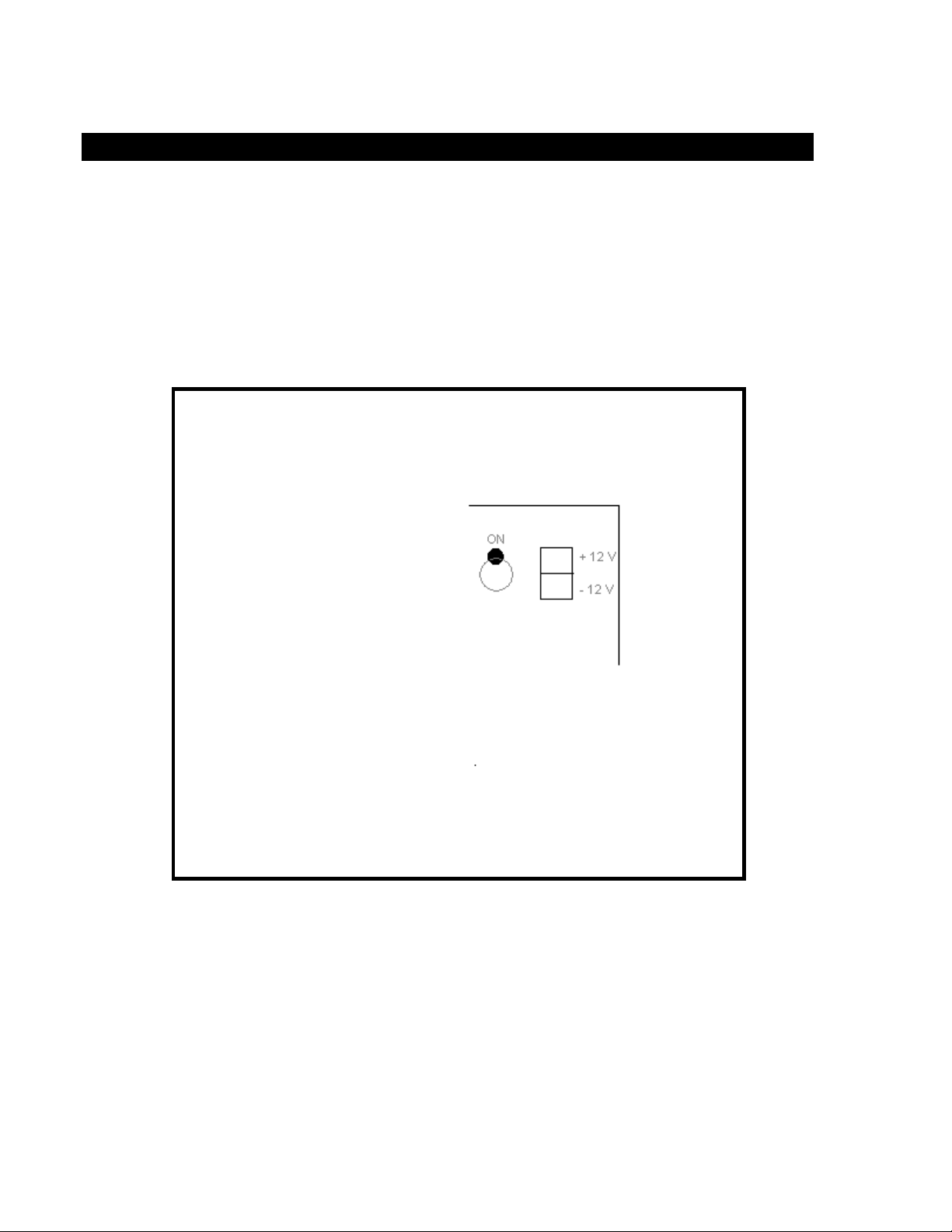
Step One - Connect the Power Supply Connect the supplied external
transformer to the 12 VDC terminals as shown in Figure 2 below. Plug the transformer
into a MicroMax Surge Suppressor (Recommended by Microtel).
MICROTEL D51T
Figure 2. Power Supply Connection
NOTE: Alternatively, you may connect any 12 to 20 Volt DC power (such as a solar
panel) to the dialer. Connect the positive side of the voltage source to 12VDC+, and the
COMMON lead to 12VDC- of the power supply terminal block of the dialer.
NOTE: Although the dialer will operate and place telephone calls when operating on its
standby battery, external power must be present whenever you wish to configure/query
the dialer from the local phone PHONE jack.
8
 Loading...