

Page 1

Microtel Series 500 Dialer
Automatic Dialer
Installation and Operation Manual
February 14, 1992
P/N 312248 Rev. B
APRIL 1, 1997
Proprietary Notice: This document and the subject matter hereto are the
property of MICROTEL, Inc. and shall not be reproduced or copied or
used for the purpose of manufacturing or sale of apparatus, except by
written permission of MICROTEL, Inc.
MICROTEL
206 West Judge Perez Drive
Chalmette, Louisiana 70043
Ph: 504.276.0571
Fax: 504.276.0574
http://www.Microtel-Inc.Com
e-mail: Microtel2@AOL.Com
Page 2

**********************************IMPORTANT******************************
When any new version of software is installed, you must initialize System, Phone, and
I/O Default Data in order to prevent unpredictable results, even if after installation the
system appears to be operating correctly.
Refer to sections III.E INITIALIZING THE SYSTEM and III.F I/O OPTION CARD
INSTALLATION of this manual, or perform the following procedure in order to correctly
reinitialize the dialer.
When in the main System Status Screen, press the SEQUENCE key to enter the Dialer
Test and Setup Screen. Cursor to the SYSTEM DATA field in the initialize Default Data
column, and press the SELECT key.
After the System Date has been initialized, move the cursor to the PHONE and I/O
DATA field and press the SELECT key.
After the PHONE and I/O DATA has been initialized, the I/O cards must be reinitialized.
Move to the Select I/O Cards field and press Select to enter the Select Device Type
Screen. Using the PREVIOUS and NEXT keys, move the highlighted cursor to each
card slot position and use the SELECT key to toggle the entry to the physical card type
which occupies that slot. After selecting the proper card type for any card position,
highlight and SELECT the INITIALIZE field to setup the system’s memory for that type
of card. When the inventory of I/O Option Cards is correct, move the highlighted cursor
to the EXIT field and press the SELECT key.
Finally, when in the Dialer Test and Setup Screen move the highlighted cursor to the
EXIT field and press the SELECT key to return to the main System Status Screen.
The System Setup, Calendar, Power, Telephone List and Directory, and individual I/O
channels must now be programmed as desired for the application. Follow the
instructions in the relevant sections of this manual in order to complete the
programming of the dialer.
Page 3

MCS-500 INSTALLATION AND OPERATION MANUAL
Table of Contents
Addendum - Rev. B Software Release 2.11 - July 8, 1993................................................................. 1
Addendum - Rev. V Software Release 2.05 - June 26, 1992.............................................................. 2
Software Release Information............................................................................................................ 3
Applicable Hardware.......................................................................................................................... 3
I. Introduction.............................................................................................................................. 4
I.A. General Information and Theory of Operation.............................................................. 4
II. Unpacking and Initial Equipment Inspection.............................................................................5
II.A. System Description and Familiarization - Chassis Cards ............................................. 5
II.A.1. LCD Panel and Keyboard......................................................................... 6
II.A.2. System Bus Assembly.............................................................................. 6
II.A.3. Power Supply Card................................................................................... 6
II.A.4. System Battery......................................................................................... 6
II.A.5. CPU Card................................................................................................. 7
II.A.6. Telephone Interface Card......................................................................... 7
II.A.7. I/O Bus Assembly..................................................................................... 7
II.A.8. Adaptive Differential Pulse Code Modulation Card................................... 7
II.A.9. Real Voice Memory Card.......................................................................... 8
II.B. System Description and Familiarization - Option Cards............................................... 8
II.B.1. Digital Input Card...................................................................................... 8
II.B.2. Analog Input Card..................................................................................... 8
II.B.3. Digital Output Card................................................................................... 8
II.B.4. Printer Output Card................................................................................... 9
III. Installation............................................................................................................................... 10
III.A. Physical System Installation...................................................................................... 10
III.B. Battery Installation...................................................................................................... 10
III.B.1. System Battery....................................................................................... 10
III.B.2. CPU and Real Voice Memory Lithium Cells........................................... 11
III.C. Electrical Power Installation....................................................................................... 11
III.C.1. Electrical Power Connection................................................................... 11
III.C.2. System Fuse........................................................................................... 12
III.D. Telephone Line Installation........................................................................................ 12
III.E. Initializing the System................................................................................................ 13
III.E.1. Accessing the Dialer Test and Setup Screen......................................... 13
III.E.2. Test and Initialization Sequences........................................................... 13
i
Page 4

III.F. I/O Option Card Installation........................................................................................ 14
III.F.1. Setting the I/O Option Card Configuration.............................................. 14
III.F.2. 8 Channel Digital Input Card.................................................................. 15
III.F.3. 4 Channel Analog Input Card................................................................. 16
III.F.4. 4 Channel Digital Output Card............................................................... 17
III.F.5. Printer Output Card................................................................................ 17
IV. Programming the System....................................................................................................... 18
IV.A. Keyboard and LCD Panel Operation - System Navigation........................................ 18
IV.B. Real Voice Speech Programming.............................................................................. 18
IV.C. System Level Programming....................................................................................... 19
IV.C.1. System ID Text....................................................................................... 19
IV.C.2. System ID Message............................................................................... 20
IV.C.3. System Snooze Period........................................................................... 20
IV.C.4 Call Spacing........................................................................................... 20
IV.C.5. Call-At...List............................................................................................ 20
IV.C.6. Access Code Number............................................................................ 21
IV.C.7. Repeats (Message Repetitions)............................................................. 21
IV.C.8 Dial Mode............................................................................................... 21
IV.C.9. Ring Count.............................................................................................. 21
IV.C.10. Calendar................................................................................................. 21
IV.C.11. Power Failure Channel........................................................................... 22
IV.C.11.a. Power Failure Channel ID Text.............................................................. 23
IV.C.11.b. Power Failure Channel ID Message...................................................... 23
IV.C.11.c. Calling Mode.......................................................................................... 23
IV.C.11.d. Return to Normal Reaction.................................................................... 24
IV.C.11.e. Telephone Number List......................................................................... 24
IV.C.11.f. Channel Delay....................................................................................... 24
IV.C.11.g. Channel State........................................................................................ 24
IV.C.11.h. Channel Latch Attribute......................................................................... 24
IV.C.11.i. Channel Alarm Condition....................................................................... 25
IV.C.11.j. Power Failure Channel Specific Snooze Period..................................... 25
IV.C.11.k. Power Failure Channel Time in Alarm Accumulator............................... 25
IV.C.11.l. Power Failure Channel Total Time in Alarm Accumulator...................... 25
IV.C.11.m. Power Failure Channel Totalizer............................................................ 25
IV.C.11.n. EXIT....................................................................................................... 25
IV.C.12. Telephone Numbers and Lists................................................................ 26
IV.C.12.a. Background on Directories and Lists...................................................... 26
IV.C.12.b. Programming Directory Entries.............................................................. 27
IV.C.12.c. To Enter Directory Telephone Numbers Into Lists................................. 28
ii
Page 5

IV.C.12.d. Establishing a Telephone List Start Position.......................................... 28
IV.C.13. Real Time Clock..................................................................................... 29
IV.D. I/O Option Card Programming................................................................................... 29
IV.D.1. Digital Input Channel Programming........................................................ 29
IV.D.1.a. Digital Input Channel ID Text Label......................................................... 29
IV.D.1.b. Digital Input Channel ID Message........................................................... 30
IV.D.1.c. Calling Mode........................................................................................... 30
IV.D.1.d. Return to Normal Reaction...................................................................... 31
IV.D.1.e. Telephone Numbers List......................................................................... 31
IV.D.1.f. Channel Delay........................................................................................ 31
IV.D.1.g. Channel State......................................................................................... 31
IV.D.1.h. Channel Latch Attribute........................................................................... 31
IV.D.1.i. Channel Alarm Condition........................................................................ 32
IV.D.1.j. Digital Input Snooze Period..................................................................... 32
IV.D.1.k. Input Channel Time-in-Alarm Accumulator.............................................. 32
IV.D.1.l. Input Channel Total Time-in Alarm Accumulator..................................... 32
IV.D.1.m. Input Channel Totalizer........................................................................... 32
IV.D.1.n. EXIT....................................................................................................... 32
IV.D.2. Analog Input Channel Programming....................................................... 32
IV.D.2.a. Analog Input Channel ID Text Label........................................................ 33
IV.D.2.b. Analog Input Channel ID Voice Message................................................. 34
IV.D.2.c. Calling Mode........................................................................................... 34
IV.D.2.d. Return to Normal Reaction...................................................................... 34
IV.D.2.e. Telephone Numbers List......................................................................... 35
IV.D.2.f. Analog Input Channel Condition.............................................................. 35
IV.D.2.g. Analog Input Channel Reading................................................................ 35
IV.D.2.h. Analog Input Channel Units..................................................................... 35
IV.D.2.i. Analog Input Channel Scaling - Zero and Span....................................... 35
IV.D.2.j. Analog Input Channel Setpoints - High and Low...................................... 36
IV.D.2.k. Analog Input Channel Delay.................................................................... 36
IV.D.2.l. Decimal Point Setting.............................................................................. 36
IV.D.2.m. Analog Input Channel Specific Snooze Period........................................ 36
IV.D.2.n. EXIT....................................................................................................... 36
IV.D.3. Digital Output Channel Programming...................................................... 36
IV.D.3.a. Digital Output Channel ID Text Label...................................................... 37
IV.D.3.b. Digital Output Channel ID Voice Message............................................... 37
IV.D.3.c. Digital Output Channel Condition............................................................ 38
IV.D.3.d. Digital Output Channel Mode.................................................................. 38
IV.D.3.e. Digital Output Channel Delay................................................................. 38
IV.D.3.f. EXIT....................................................................................................... 38
iii
Page 6

IV.D.4. Printer Output Card Programming........................................................... 38
IV.D.4.a. Printer Output Enable.............................................................................. 39
IV.D.4.b. Printer Output Reset............................................................................... 39
IV.D.4.c. Printer Output Form Feed....................................................................... 39
IV.D.4.d. Printer Output System Setup Information................................................ 39
IV.D.4.e. Printer Output Test.................................................................................. 39
V. Local System Operation......................................................................................................... 40
V.A. Viewing System Screens........................................................................................... 40
V.A.1. Viewing System Screens......................................................................... 40
V.A.2. Digital Input Card.................................................................................... 40
V.A.3. Analog Card............................................................................................ 41
V.A.4. Digital Output Card................................................................................. 41
V.B. Putting the System into the Active or Run Mode........................................................ 42
V.C. Putting the System into the Inactive or Halt Mode...................................................... 42
V.D. When an Alarm Occurs.............................................................................................. 42
V.E. When a Call is Placed to the System......................................................................... 44
VI. Remote System Operation..................................................................................................... 45
VI.A. System Level Programming....................................................................................... 45
VI.B. Digital Input Channel Programming........................................................................... 45
VI.C. Analog Input Channel Programming.......................................................................... 46
VI.D. Digital Output Channel Programming......................................................................... 46
VI.E. Intercom Functions.................................................................................................... 46
VI.F. Voice Mail Message Entry, Access, and Delivery....................................................... 47
VI.G. Telephone Number List Management Functions........................................................ 47
VI.H. Directory Number Management Functions................................................................. 47
VII. System Maintenance............................................................................................................. 48
VII.A. Adjusting System Amplitude Levels........................................................................... 48
VII.B. System Battery........................................................................................................... 48
VII.C. RV Memory Battery.................................................................................................... 48
VII.D. CPU Clock Battery...................................................................................................... 49
VII.E. I/O Expansion.............................................................................................................. 49
VII.F Customer Service...............................................................................................
Appendices....................................................................................................................................... 50
Physical Installation Diagram................................................................................................... 52
Electrical Installation Diagram.................................................................................................. 54
Screen Navigation Diagram.....................................…………..............................................……56
Remote Operation Procedure Flowchart................................................................................. 57
.........…..49
iv
Page 7

Analog Channel Setup and Calibration Example.................................................................... 60
Installation Checklist............................................................................................................... 61
Directory Telephone Number Worksheet................................................................................ 62
Telephone List Worksheet...................................................................................................... 64
v
Page 8

Addendum to the MCS 500 Automatic Dialer Operation Manual, Rev. B
Software Release 2.11
July 8, 1993
Additional Feature PROGRAMMABLE START MODE
Some applications desire that the dialer powers up in an active calling mode. A
Start MODE field has been added to the System Setup screen which allows the
user to program the dialer to enter either a half or run state upon power up. This
selection is made by entering the System Setup screen and toggling the Start
MODE field between the HALT and RUN choices.
Operational Change LATCHED ALARM VOICE MESSAGE
The alarm voice message now reports the state of an alarm channel, instead of
the current state, until the alarm has been acknowledged. So, if an alarm
occurred on a channel programmed to Latch, and then the channel returned to
normal, the voice message will report that channel is in alarm until the alarm is
acknowledged.
1
Page 9

Addendum to the MCS 500 Automatic Dialer Operation Manual, Rev. V.
Software Release 2.05
June 26, 1992
Additional Feature USE OF THE # AND * KEYS AS TELEPHONE NUMBERS
Some Dialer applications involve paging systems which frequently use some of
the non-digit telephone tone keys. For programming telephone numbers which
must contain the # and * keys into directory positions use the following
procedures:
1. To enter the # character into a telephone number use the magenta key
(pink).
2. To enter the * character into a telephone number use the cyan key (blue).
3. To enter a 2 second pause into the telephone numbers use the SP key
(also named RUN).
Additional Feature AUTOMATIC ACKNOWLEDGMENT OF ALARMS
Some applications desire that the dialer place telephone calls, and automatically
enter the snooze period, as if a call had been acknowledged. A field has been
added to the telephone number directory programming which allows the user to
designate a telephone number as an Automatic Acknowledged telephone
number. This selection is made by toggling the acknowledge field between the
“Required” and “Automatic” choices. When the system encounters and dials a
number designated as Automatic Acknowledge, the number will be dialed and
the call will be completed. The system will then acknowledge all existing alarms,
and enter the snooze period for the programmed duration.
Clarification PARALLEL PRINTER OPTION
The figure on page 14 of the manual illustrates the position of the DB-25 Printer
Port. Although the figure uses the work “Serial” to identify the location of the DB25 Serial type port, the system requires the use of a parallel printer.
MICROTEL,INC recommends the use of Epson parallel printers with the use of
the MCS 500 Printer Option Card.
2
Page 10

Software Release Information
This manual pertains to the MCS 500 dialer, with the following software releases:
CPU Card ROM1 M500 2.xx 2/28/92*
Voice Memory Card ROM1 500VOC1.M03 12/20/91
Voice Memory Card ROM2 500VOC2.M03 13/10/91
To view the software release date on the memory devices in the Dialer, depress the
SEQUENCE key and choose the Sequence function entitled VERSION.
*Dates may be different depending upon actual engineering release and software
maintenance activities. What is important is that the version number of the manual,
M500 2.xx (where xx=00 to 99) correlates to the version number of the software in the
unit, as it is viewed using the SEQUENCE VERSION key entries.
Applicable Hardware
This manual pertains to the MCS 500 Automatic Dialer containing a CPU card assembly
part number 734293. This circuit board assembly contains the necessary Flash
memory and SRAM capacity to support the software and user features in software
release 2.xx and beyond. A Read Only Memory (ROM or Program Memory) is also
included on the CPU card, containing the software release version 2.xx.
3
Page 11

I. INTRODUCTION
I.A. General Information and Theory of Operation
The Microtel MCS 500 Dialer is a complete Automatic Dialing telemetry system, capable
of fulfilling virtually any type of alarm monitoring or data acquisition need. The basic
system is capable of monitoring alarm conditions on a variety of analog and digital
channels, and advising personnel of the conditions which exist at the remote monitored
site. Upon detection or determination of an alarm condition, the system will place a
series of telephone calls to as many as 64 different telephone numbers. Using its own
“default” voice messages or using user-entered “Real Voice” messages, the system will
advise the call recipient of the location and the nature of the alarm conditions which
caused the call sequence.
A variety of programmable features make the Microtel MCS 500 Dialer the most
versatile and sophisticated alarm dialer available. An extensive remote programming
capability allows the user to reprogram the system using a standard tone dialing
telephone.
The system contains separate computer and I/O buses, allowing field configuration,
upgrading, and expansion of the basic system to meet the individual needs of the user.
Whether the monitoring requirement is 8 channels or 40 channels, with digital inputs,
analog inputs, or relay outputs - the system may be field configured and upgraded
without removing it from service.
A unique voice mail feature allows the user to send messages of interest to other
personnel involved with a monitored site. Voice mail messages are either deposited in
the system for access by other callers, or may be delivered by the system to any other
telephone number.
.
II. UNPACKING AND INITIAL EQUIPMENT INSPECTION
Microtel takes all possible precautions in packaging each item to prevent shipping
damage. Carefully inspect each package at the time of receipt for signs of physical
damage. Report damage claims to the shipping agent involved immediately. Do not
install damaged Equipment with suspected damage.
All instructions given on any attached labels or tags should be followed. Carefully
inspect all packing material before discarding it to prevent loss of accessories, mounting
hardware, spare parts, or instruction. If the unit is not to be installed immediately,
repack it in the shipping carton to protect it in storage.
NOTE: The manual should be reviewed prior to installation and operation of the system
4
Page 12
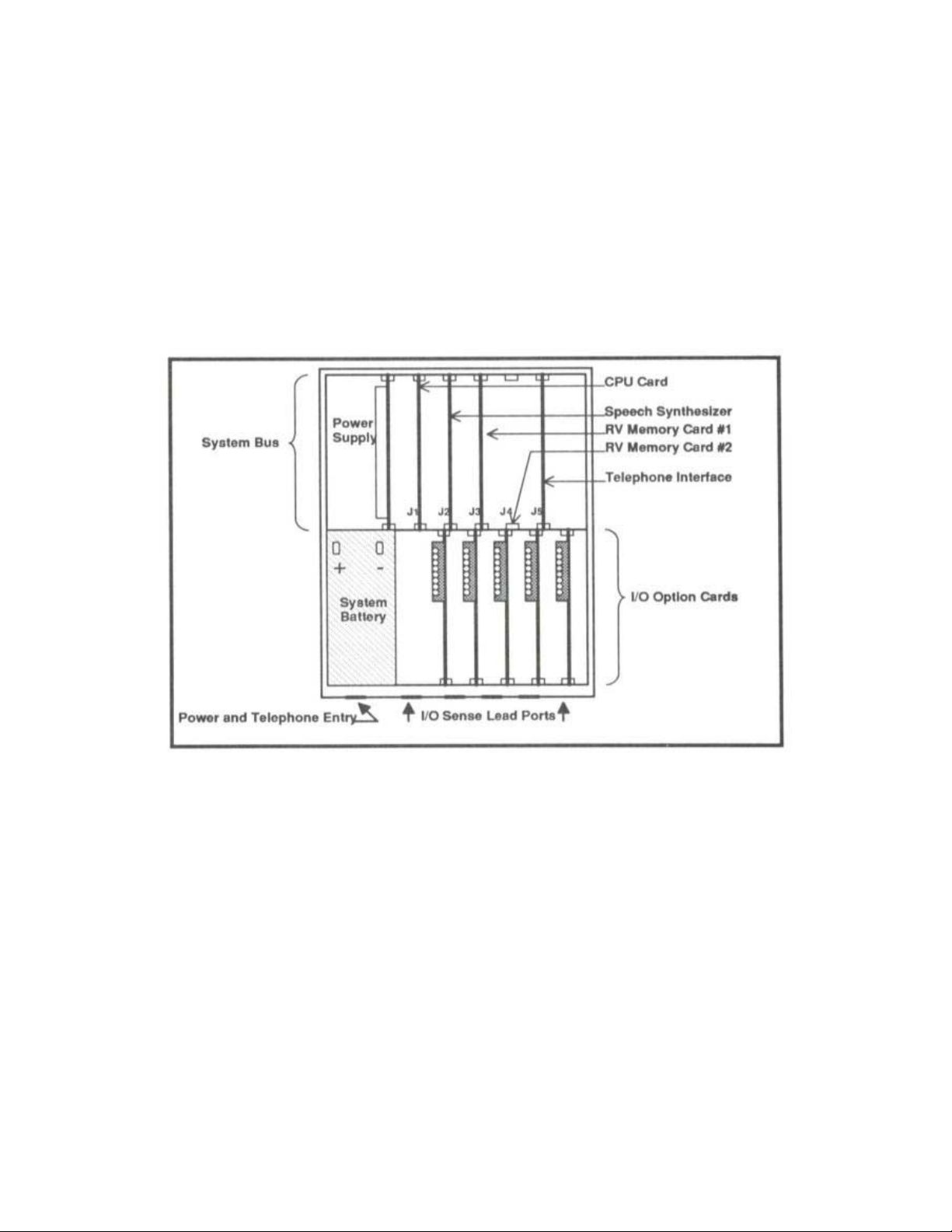
II.A. System Description and Familiarization - Chassis Cards
The following section is intended to familiarize the user with the basic components of
the Microtel MCS 500 Dialer. The system is housed inside a NEMA12 fiberglass
enclosure. On the bottom side of the enclosure are five, 3/4 inch conduit-size holes for
the routing of power lines, telephone lines, the system microphone, and alarm channel
sensing conductors, and printer output connections. Inside the door of the enclosure is
the system chassis which is divided into several sections. These sections and the
circuit elements which reside therein are described below. The following figure
illustrates the major components of the MCS 500 system.
5
Page 13

II.A.1 LCD Panel and Keyboard
The door of the inner chassis contains the system’s 20-key keyboard and the LCD
display panel. These circuit modules are connected to the System Bus via a 20
conductor flat cable.
II.A.2. System Bus Assembly
Located in the upper section of the chassis is the System Bus. The Bus and card cage
contains printed circuit board connectors sockets for up to five circuit cards. Two of the
plug-in circuit card connectors are specifically designed to accept the CPU card (card
slot J1) and the Telephone Interface Card (card slot J5). The other three slot positions
(J2, J3, and J4) accept other system level circuit cards such as the Speech Synthesizer
card and the Speech Memory cards. The System Bus contains all circuitry necessary to
route audio and computer signals from card to card, and out to the I/O bus located in
the lower section of the System Chassis.
II.A.3. Power Supply Card
Located to the left of the System Bus Card, and directly above the Battery well, the
Power Supply occupies the extreme left card position. The Power Supply Card does
not, however, plug directly into the System Bus Card. The Power Supply delivers power
to the entire system, and contains indicators for AC Power, +5 Volts Power, +12 Volts
Power, and Low Battery. Additionally, the Power Supply Board contains a three
position terminal strip for incoming AC power, a 1/2 Amp fuse, and the system power
switch.
II.A.4. System Battery
The system battery is located to the left of the I/O bus card cage. The battery is a 12
volt, 7.0 ampere-hour battery, capable of powering the system through extended power
outages. The total battery backup time is dependent upon several factors, but it is
primarily related to the types of option cards installed in the system and the age of the
battery. The following matrix illustrates the typical battery lift for various combinations of
Digital and Analog Input Cards.
6
Page 14

II.A.5. CPU Card
The CPU card must occupy J1, the left most circuit card connector on the System Bus.
The CPU Card contains the system’s primary microprocessor, program and data
memory, and interface circuitry for the other cards connected to the bus. The card has
a socket for a lithium battery which must be enabled to provide ongoing operation
for the Real Time Clock, also located on the CPU Card. To enable the CPU battery,
refer to the System Maintenance section of this manual.
II.A.6. Telephone Interface Card
The Telephone Interface Card must occupy J5, right-most circuit card connector on the
System Bus. The Telephone Interface card contains circuitry to connect the system to
the telephone network and to provide electrical protection to both the system and the
telephone network. The telephone line to which the system is connected plugs into the
RJ11C jack located on the Telephone Interface Card.
II.A.7. I/O Bus Assembly
The I/O Bus is located in the bottom section of the chassis, to the right of the battery
well. The I/O contains five circuit card connectors, into which the system’s I/O option
cards are to be inserted. The I/O option cards, such as the 8 channel Digital Input Card,
the four channel Analog Input Card, the four channel Digital Output Card, and the
Printer Output Card are connected to the sensors and outputs which the system is to
monitor and control during operation. The I/O Bus card connects to bus interface
circuitry located on the System Bus card, using a flat ribbon connector and cable.
The I/O Bus Card also distributes power from the Power Supply Card to the balance of
the system. The I/O Bus Card has a six-conductor cable and plug assembly which
plugs into the connector posts provided on the Power Supply Card. The System Bus
Card has a five-conductor cable and plug assembly which plugs into the connector
posts provided on the I/O Bus Card.
The I/O Bus Card also contains an Alarm-In-Process relay, which is activated whenever
the system is trying to reach someone over the telephone network. This relay may be
used to power an external alarm signaling device.
II.A.8. Adaptive Differential Pulse Code Modulation Card (ADPCM)
The ADPCM Card plugs into System Bus slot 2, 3, or 4. The Card contains all circuitry
necessary to articulate any speech programmed into the system by the user. The
system also has an internal vocabulary sufficient to provide default messages for each
channel, and to provide prompting for operation conducted over the telephone
connection. The system CPU delivers speech data from the REAL VOICE MEMORY
Card to the ADPCM card during system operation. The ADPCM Card contains a jack
7
Page 15

for the optional microphone used for the intercom audio monitoring functions. The Card
also contains a small RJ style jack which accepts the carbon element telephone
handset used for entering Real Voice speech for describing all alarm and monitoring
channels.
II.A.9. Real Voice Memory Card (RV)
The RV Memory Card(s) plugs into System Bus slot 2, 3, or 4. If more than three I/O
cards are used in the system (excluding the Printer Output Card) then the system must
use two (2) RV Memory Cards. The RV Memory Card contains EPROM memories
which are programmed with the system’s “core” vocabulary - those words and phrases
necessary to articulate default messages, numerics, and prompting. Additionally, the
RV Memory Card contains eight CMOS SRAMS into which the CPU places “Real Voice”
speech data programmed by the user during programming of each channel’s
identification. The card has a socket for a lithium battery which must be enabled to
provide long-term protection for the speech data. To enable or replace the RV Memory
lithium battery, refer to the System Maintenance
II.B. System Description and Familiarization - Option Cards
Various combinations of the following circuit cards may be located in the I/O Option
Card bus on the lower half of the dialer. The cards may be installed in the field, by the
user. The user must program the dialer so that it may recognize what complement of
I/O Option Cards are installed. To select the option boards to be used, see the section
entitled, Setting the I/O Option Card Configuration
II.B.1. Digital Input Card
The Digital Input Card contains a terminal strip which will accept eight input channels.
The terminal strip provides two connectors for a common ground conductor. Each fault
sensing current “loop” is provided with 10 mA of sensing current by the system. Each
input channel is programmable for a variety of options, including integration times,
Normally-Open or Normally-Closed operation, call list, and ID Message. Time-In-Alarm
and Totalizer values are maintained by the system CPU for each input channel.
II.B.2 Analog Input Card
The Analog Input Option Card accepts four channels of 4-20 mA signals. Each channel
may have its own label, message, scaling factors, set-points, and archive
configurations.
II.B.3. Digital Output Card
The Digital Output Option Card contains four SPDT 5 amp relays. The relays may be
operated over the telephone line using telephone tone commands.
section of this manual.
.
8
Page 16

II.B.4. Printer Output Card
The printer Output card contains circuitry which allows the dialer to print alarm logs and
other information on a standard parallel printer, employing a standard parallel interface.
The printer card must interface to the printer via a cable assembly. If the printer Output
Card is being added in the field, then the cable assembly must be routed through the
enclosure wall as described in the Printer Card Installation instructions.
9
Page 17

III. INSTALLATION
Installation Note:
During the Installation and Programming of the MCS Automatic Dialer, it is helpful to
use the Installation Checklist, found in the appendix. Worksheets for programming
Directory Telephone Lists are also available in the appendix.
III.A. Physical System Installation
Mount the system on a wall or other vertical surface, away from and protected from
harsh extremes. It is also recommended that the unit not be placed in close proximity to
high voltage (480 V and higher) electrical equipment. Four mounting holes on the top
and bottom mounting lips are to be used for system mounting.
There are six access holes on the bottom of the unit. The two left side ports are for
power connection and the system’s telephone line connection. The right side ports are
intended to be used for the entry of input/output conductors.
The Physical Installation Diagram, found in the appendix, shows the recommended
dimensions to be used in the physical installation of the system.
III.B. Battery Installation
III.B.1. System Battery
The battery installs in the bottom left side of the system. Open the system front panel
and retrieve the red and black battery leads from beneath the battery pocket area,
located to the left of the I/O Bus assembly. Connect the battery lead terminals on to the
new battery, BEING CERTAIN that the red lead connects to the positive (+) battery
terminal, and the black lead connects to the negative (-) battery terminal.
Insert (do not force) the battery, terminals pointed upwards, completely into the battery
pocket and close the system front panel. A new battery will take no longer than 24
hours to gain a full charge, and will be capable of powering the system through power
outages many hours in length. Actual battery backup time is dependent upon the
number of channels being monitored and the number of output relays which may be
activated. It should be noted that the LOW BATTERY indicator is only valid when the
120 VAC power is on. If the LOW BATTERY indicator stays on for more than 24 hours,
the battery is in need of replacement. Contact Microtel for replacement batteries. The
Microtel part number for the System Battery is #312156.
10
Page 18

III.B.2. CPU and Real Voice Memory Lithium Cells
A lithium battery is provided on the CPU card and the Real Voice Memory card. Each
of these lithium batteries must be enabled so that memory and clock functions survive
long term power outages. These batteries are enabled using the jumper plugs provided
with each card. These batteries do not recharge and should be replaced if they are
found to have less than 2.5 volts. Contact the Microtel Customer Care hot line, at (504)
276-0571 for replacement batteries. The Microtel part number for the CPU and Real
Voice lithium batteries is #312115.
III.C. Electrical Power Installation
SAFETY NOTICE!!
Be certain that the system has an adequate Earth Ground. Insufficient Earth Grounding
can prevent the internal protection circuitry from performing properly, and may cause
damage to the system.
III.C.1. Electrical Power Connection
Electrical power may be applied by connecting the three power leads (Hot, Neutral, and
Earth Ground) to a three wire 120 VAC supply. It is recommended that a separate
circuit breaker be used with the system. Remember that when the breaker is on, and
the unit is so connected, live 120 VAC is contained within the system even though the
system power switch may be turned off. Refer to the System Wiring and Mounting
diagram located in the appendix for details on wire routing procedures.
If the unit is to be installed in a location where large or high voltage motors are in use, a
separate, external power line transient suppresser is recommended (Micromax surge
suppressor). This insures that the unit is not affected by surges and spikes occurring in
the 120 VAC power. If such a device is needed, contact Microtel for assistance.
SAFETY NOTICE!!
Never ship the system with the battery installed. Remove 120 VAC Power from the
System and turn the Power Switch OFF before removing, replacing, or installing the
System Battery
11
Page 19

III.C.2 System Fuse
g
ying
The internal System fuse is a 1/2 amp fuse, Little fuse #312.500, or equivalent. The
fuse is located on the Power Supply Board in a set of fuse holder clips.
SAFETY NOTICE!!
When inspectin
breaker suppl
III.D. Telephone Line Installation
The Microtel MCS 500 Dialer comes with a standard 3 ft. flat telephone cable for easy
connection to an RJ-11C type modular jack. The cable is connected to the Microtel
MCS 500 Dialer at the factory. The only field installation requirement is to insert the
male connector end of the cable into the user supplied RJ-11C jack. Refer to the
installation diagram located in the appendix for details on wire routing procedures.
The Microtel MCS 500 Dialer complies with part 68 of the FCC rules. On the inside of
this unit is a label that contains, among other information, the FCC registration number
and the Ringer Equivalence Number (REN). If requested, provided this information to
your Telephone Company.
The REN is useful to determine the quantity of devices you may connect to your
telephone line and still have all of those devices ring when your number is called. In
most, but not all areas, the sum of the RENs of all devices should not exceed five (5.0).
To be certain of the number of devices you may connect to your line, you should call
your local Telephone Company to determine the maximum REN for your calling area.
If the Microtel MCS 500 Dialer causes harm to the telephone network, the Telephone
Company may discontinue your service temporarily. If possible they will notify you in
advance. If advance notice is not practical, you will be notified as soon as possible.
You will be advised of your right to file a complaint with the FCC.
Your Telephone Company may make changes in its facilities, equipment, operations or
procedures that could effect the proper operation of the Microtel MCS 500 Dialer. If
they do so, you will be given advanced notice so as to give you an opportunity to
maintain uninterrupted service.
If you experience trouble with the Microtel MCS 500 Dialer, please contact Microtel at
206 West Judge Perez Drive, Chalmette, LA 70043, (504) 276-0571, for repair /
warranty information. The Telephone Company may ask you to disconnect the
equipment from the network until the problem has been corrected or you are sure that
the equipment is not malfunctioning.
or replacing the System fuse, unplug the System or turn off the
power to the System.
12
Page 20
Repairs that you are authorized to make on the Microtel MCS 500 Dialer include
replacing the fuse, replacing the battery, and exchange of the power supply and certain
other plug-in circuit cards.
The Microtel MCS 500 Dialer may not be used on coin service equipment provided by
the Telephone Company. Connection to party lines is subject to state tariffs (contact
your state public utility commission or corporation commission for information).
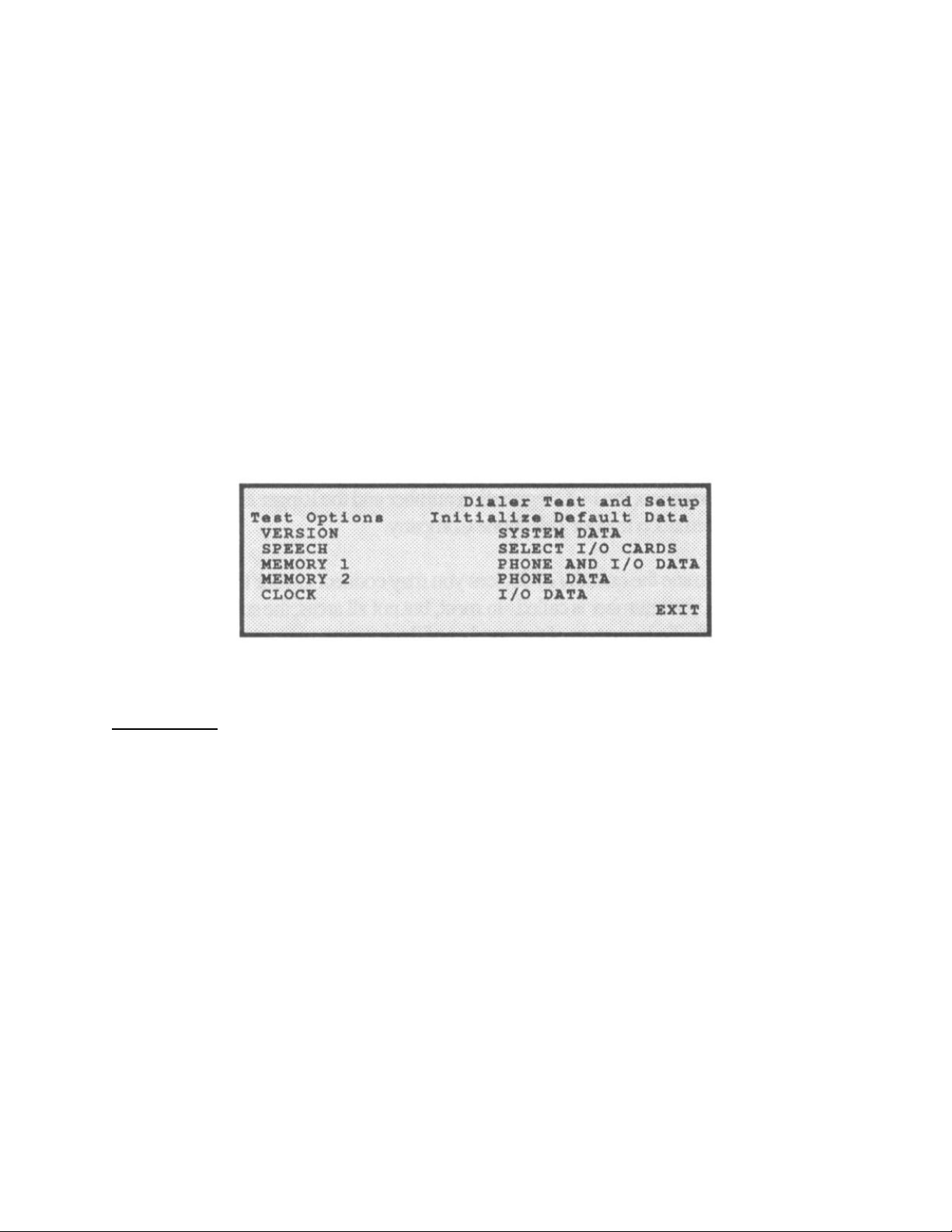
III.E. Initializing the System
III.E.1. Accessing the Dialer Test and Setup Screen
From the System Status Screen, press the SEQUENCE key to access the Dialer Test
and Setup Screen. This Screen contains many sequences which are used to setup
(initialize) the system and to test various functions. Use the PREVIOUS and NEXT
keys to access the functions and the SELECT key to invoke them.
III.E.2. Test and Initialization Sequences
Test Options
VERSION When selected, this sequence shows the software program release
SPEECH When selected, this sequence causes all internal “core” vocabulary
MEMORY1 When selected, this sequence tests Real Voice Speech Data
MEMORY2 When selected, this sequence tests Real Voice Speech Data
numbers and dates. Press any key to return to the Dialer Test and
Setup Screen.
to be articulated.
memory locations on RV card #1. This test takes approximately
two minutes to complete. Any user programmed digitized speech
data is retained during this test.
memory locations on RV card #2.
13
Page 21

CLOCK When selected, this sequence makes a Real Time clock calibration
signal available on the CPU.
Initialize Default Data
SYSTEM DATA When selected, this sequence Initializes all System Data, returning
all data on the System Setup Screen to their default values.
Performing this sequence during initial system startup returns all
I/O Card Selections to SPARE cards.
SELECT I/O
CARDS This sequence is used to tell the system which I/O cards are
installed. See the next section for detailed information on selecting
I/O cards for the system.
PHONE AND
I/O DATA When selected, this sequence initializes all Telephone Directory,
Telephone List, and I/O card data to default values. I/O cards
selections are retained but all data for each card is cleared to
default values. I/O channel message IDs are returned to the
default messages, but any previously programmed digitized speech
data is still in memory. Reverting to an initialized channel’s
digitized speech ID may be accomplished by depressing
SEQUENCE while on the channel’s Setup Screen.
PHONE DATA
When selected, this sequence initializes all Telephone Directory
and Telephone List data as described above.
I/O DATA
When selected, this sequence initializes all I/O channel data as
described above.
III.F. I/O Option Card Installation
III.F.1. Setting the I/O Option Card Configuration
The MCS 500 Dialer may be user configured to accept a variety of I/O combinations.
Using the keyboard and display, one may access a screen which allows the selection of
a different type of option card for each of the five I/O card slots in the system.
Currently, there are four types of I/O option cards:
Digital Input Card 8 Channels of digital input
Analog Input Card 4 Channels of 4-20 mA input
Relay (Digital) Output Card 4 Channels of SPDT Relay Outputs
Printer Output Card Parallel Printer Interface
14
Page 22
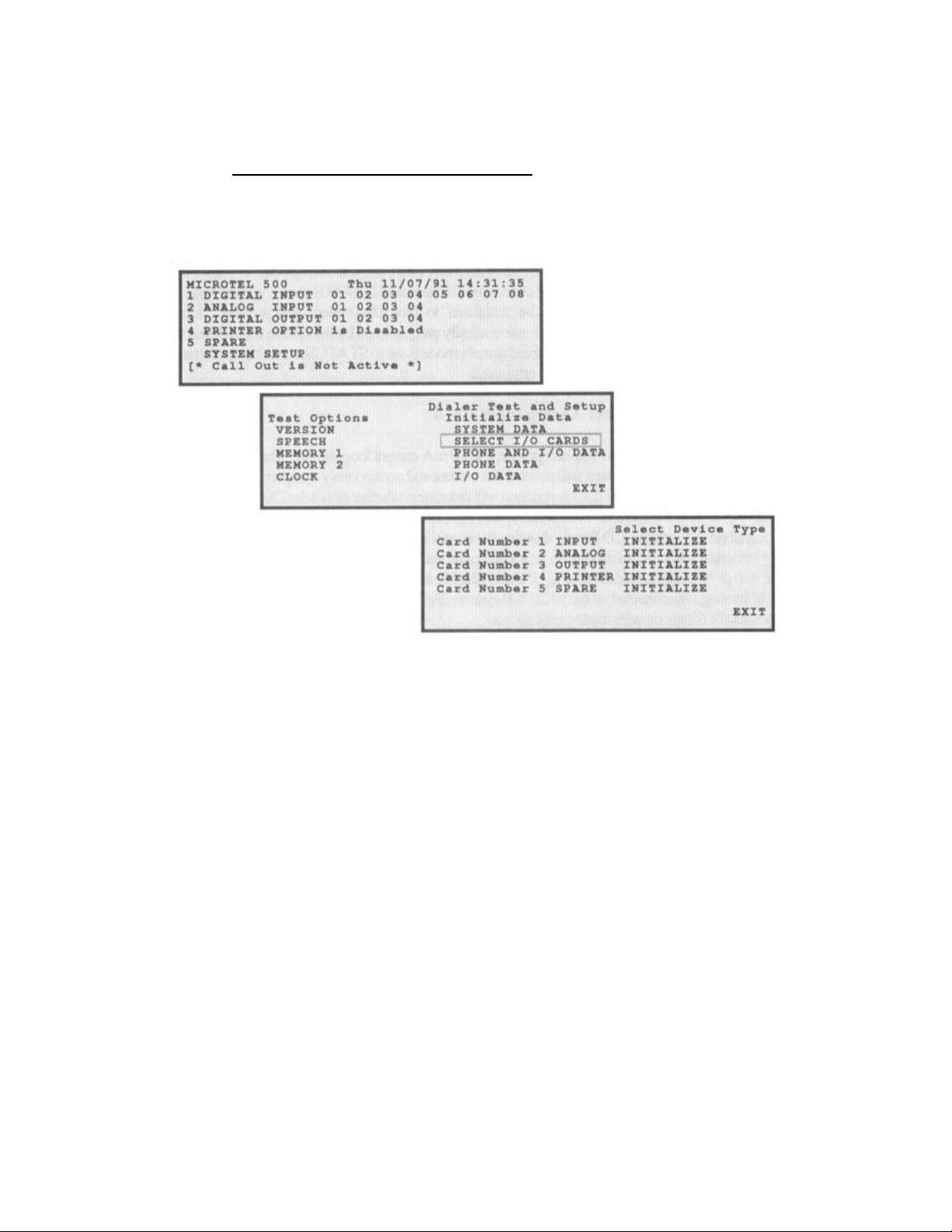
An overview of the “navigation” through the many screens which are accessed to
configure and program the many features of the dialer may be found in the appendix
chart entitled, System Screen Navigation Diagram
of I/O cards in the system, access the System status Screen by pressing HALT. Press
the SEQUENCE key to access the Dialer Test and Setup Screen. Then use the
PREVIOUS and NEXT keys to access the Select I/O screen as shown below.
. To configure the type and location
Using the PREVIOUS and NEXT keys, move the highlighted cursor to each card slot
position and use the SELECT key to toggle the entry to the physical card type which
occupies that card slot. Card slots are numbered from 1 to 5, beginning from the left
side of the lower card cage. After selecting the proper card type for any card position,
highlight and SELECT the INITIALIZE field to setup the system’s memory for that type
of card. When the inventory of I/O Option Cards is correct, move the highlighted cursor
to the EXIT field and press the SELECT key.
) IMPORTANT - CIRCUIT CARD ORIENTATION - IMPORTANT
All circuit cards in the system should be oriented so that that the components are facing
towards the LEFT side of the system. Reversal of the cards may cause damage to the
system.
15
Page 23

III.F.2. 8 Channel Digital Input Card
The 8 Channel Digital Input card is designed to accept up to eight channels of dry (unpowered), normally open or normally closed signal lines. The system provides a small
sampling current (<10mA) to determine if the contact is open or closed. Wires from
normally open or normally closed switches may be routed through the conduit port at
the lower right side of the system. Connect each wire pair to its appropriate channel
input terminal and one of the two common ground terminals provided on the digital Input
circuit card. Shielded, twisted pair, #20 or #22 gauge wire is recommended. If shielded
cable is used, ground the shield at the sensor and leave the shield floating
(disconnected) at the Dialer system. Refer to the Electrical Installation Diagram
located
in the appendix for details on wire routing procedures.
Each input channel must be configured to be either normally open or normally closed.
A channel is normally open if the “no fault” or “normal” condition is that condition which
consists of an open circuit on the channel’s wire pair. The normally open or normally
closed state of each channel may be programmed as outlined in the Section entitled,
Programming the System
.
Any unused channels should be programmed as normally open, and left unconnected to
reduce overall system current consumption. Setting the Mode of an unused Channel to
IGNORE speeds up the System operation. When the option card is installed it must be
“initialized” to inform the system of its presence. During initialization, each digital input
channel is automatically programmed by the system for various operation data values
(default values). The default for the channel’s mode is set to STATUS, meaning its
alarm condition is reported, but it will not cause calls to be originated.
III.F.3. 4 Channel Analog Input Card
The Analog Input option card will accept four, 4 to 20mA current loop signals. The
current loop signal must be externally powered. The System will monitor the current
and continuously compare the reading against high and low set-points. The results of
that comparison will determine whether or not the dialer places a telephone call
because of an alarm condition. Additionally, the High, Low, and Normal indications for
each channel may be displayed on the system LCD panel, showing the monitored
status of each channel. Two wire, shielded cable may be connected to the terminal
strip provided on the analog option card, for each channel. Shielded, twisted pair, #20
or #22 gauge wire is recommended. If shielded cable is used, ground the shield at the
sensor and leave the shield floating (disconnected) at the MCS 500 system. Refer to
the Electrical Installation Diagram
located in the appendix for details on wire routing
procedures.
During card initialization, each analog input channel is automatically programmed by the
system for various operation data values (default values). The default for the channel’s
mode is set to IGNORE, meaning it is completely disregarded by the system. This is
done to assure that the system spends no wasted time on invalid or unused channels.
16
Page 24

III.F.4. 4 Channel Digital Output Card
Each Digital Output Option card provides four SPDT 5 amp relays for controlling
external devices and loads. Using telephone tone commands discussed later in this
reference, each channel may be turned on or turned off. Additionally, the mode of each
relay may be set to a latched or momentary configuration. If a channel is configured as
a momentary mode, it will remain on for a programmable period of time when activated
with the tone command. Relays may also be controlled from the System front panel.
The output for each channel is comprised of the relay common and either the normally
open (N/O) or normally closed (N/C) relay terminal. The choice of normally open or
normally closed output is selectable using the jumper plugs provided for each channel.
III.F.5. Printer Output Card
Although the Printer Output Card can reside in any of the I/O card slots in the MCS 500
Dialer, it is recommended that it be installed in the fifth, or right-most position. The card
has a 26 pin array of connector pins which must interface to a DB-25 jack on the outside
of the system enclosure. A printer cable assembly is used to connect to the pins on the
card to the DB-25 jack assembly, which is mounted over one of the conduit holes on the
bottom side of the dialer enclosure. When connecting the printer cable assembly to the
Printer Option Card, be sure to observe the correct pin 1 polarity of the plug and jack
combination.
The following diagram details the installation of the Printer Output Card:
17
Page 25

IV. PROGRAMMING THE SYSTEM
The Microtel MCS 500 Dialer is programmed and configured for operation using a
keyboard programming system, described within this section. The programming
methodology involves selecting a programmable item, editing it, and entering the
change. Cursor control and item selection sequences are accomplished using three
keys located on the system keypad. Once programmed, the user need only depress
RUN or HALT to enable or disable the system operation. Although the system may be
programmed with operational data at any time it is recommended that the system be
placed in the HALT mode before programming. The system will enter the HALT mode
(Call outs will not be active) after application of power, or after depressing the HALT
key. Attention is directed to the System Screen Navigation Diagram
appendix, which offers significant detail in the programming methodology of the system,
including how some screens are used to access more detailed ones “beneath” them.
IV.A. Keyboard and LCD Panel Operation -- System Navigation
Within this section, CAPITALIZED words represent keypad entry selections and modes
of operation. Items enclosed within brackets [ ] and separated by commas represent
alternative selections. Phrases which are enclosed within quotation marks “ ” represent
phrases which are articulated by the system.
Upon the application of power to the system, the LCD display panel will show a screen
called the System Status Screen. This screen shows the current status of all monitoring
channels, along with the current data and time. From the screen, using the LEFT
ARROW, RIGHT ARROW, and SELECT keys, different screens may be accessed for
programming or viewing setup information.
IV.B. Real Voice Speech Programming
Real Voice messages may be substituted for default messages which are articulated by
the system. To program these messages, move to the screen associated with the
channel of interest, and use the following keys for recording and playing back the
speech entries. Use a handset plugged into the Real Voice speech card to record and
listen to messages as they are programmed.
PLAY - Recites the current message.
RECORD - Records the current message.
SEQUENCE - Resets the current message to its default message, using
the system voice rather than digitized, Real Voice.
, found in the
18
Page 26

The following is a list of the different messages which may be programmed by the user
for each type of channel or category:
Message Duration Default Message
System ID 6 seconds “Microtel System 500”
Digital Input 3 seconds “Digital Input xx”
Digital Output 6 seconds “Digital Output xx”
Analog Input 6 seconds “Analog Input xx”
Voice Mail Message remaining memory
All other messages which the dialer articulates are composed by the system, using
synthesized speech data resident in the system. These messages are primarily used
during remote programming operations, where the user receives speech prompting
during telephone tone key entries.
IV.C. System Level Programming
To program the items which are classified as System Level, the System Setup Screen
must be selected. To do so, first press the HALT key. The system Status Screen will
be displayed. Using the cursor control keys highlight SYSTEM SETUP and depress
SELECT. System level data may now be selected and edited using the following
procedures.
IV.C.1. System ID Text
The System ID Text is the name given to the MCS 500 in its installed application. The
name may be up to 16 alpha-numeric characters in length. The default System ID Text
is Microtel 500.
To change the ID test, cursor to the field, and press the SELECT key. The first
character of the field will flash, indicating it is available for editing. Enter digits or
alphabetical characters, filing the field with up to 16 characters ID test. To enter
alphabetical characters (including space-SP, and period-.) use a dual key entry
preceded by the BLUE or the RED keys. The cursor control keys may be used to freely
move back and forth, from character position to character position within the field.
19
Page 27

When the entry is satisfactory, press the SELECT key to commit it to the system’s
memory.
Pressing a cursor control key (NEXT and PREVIOUS) will cause the highlighted cursor
indicator to appear on either the next or the same field.
IV.C.2. System ID Message
The System ID Message is a 6 second Real Voice message that introduces which
system is speaking when it calls or when it is called over the telephone line. To
program the System ID Message, a carbon element telephone handset must be
connected to the Speech Digitizer card inside the system enclosure. The ADPCM card
is located in system bus card slot 2, 3, or 4, and contains a small modular jack which
will accept the plug found on a telephone handset. This socket is smaller than the jack
used for the telephone line connection.
IV.C.3. System Snooze Period
The Snooze Period is that time that the system waits after a call placed by the system
has been answered and positively acknowledged. The Snooze Period may be from
0001 to 9999 minutes. To program the Snooze Period, cursor to that field and select it
for editing. Use the numeric entry keys to enter the desired value, pressing ENTER to
commit it to memory. The default Snooze Period is 60 minutes. Individual channels
may specify individual Snooze Periods. If a Channel specific Snooze period is set to
the default value (using one of the Sequence reset functions), the value to which it will
be returned will be the System Level Snooze Period.
When the system is in the Snooze Period Mode, it will answer incoming calls and deliver
a status message. If another new fault or alarm condition arises, the balance of the
delay will be aborted, and the system will begin repeated calls again, advising personnel
of the new fault conditions(s).
IV.C.4. Call Spacing
Call spacing is that period in-between unacknowledged calls made by the system. It
may range from 0 to 9999 minutes. To program a call spacing value, cursor to that field
and select it for editing. Use the numeric entry keys to enter the desired value, pressing
ENTER to commit it to memory. The default Call Spacing delay is 1 minute.
IV.C.5. Call-At...List
The dialer may be instructed to call at a certain (and different) time of day, for each day
of the week, regardless of the fault or alarm condition which exists. The Call-At times
are set on the CALENDAR screen, but the CALL-AT LIST determines which telephone
list will be used for telephone numbers. The list is programmed by accessing that field
20
Page 28

and entering any list number from list 00 to 15 value. The default list for all calls is list
01. (As will be noted in detail later, a special telephone number list 00 is reserved for
those calls which must be placed regardless of any system call exclusion periods such
as Call Period)
IV.C.6. Access Code Number
When the system is on the telephone line, it may be accessed so that changes may be
made remotely. Before such access is available, the system Access Code must be
properly entered. To enter this security code, select that field and enter a four digit
number. The default value for the Access Code is 1234.
IV.C.7. Repeats (Message Repetitions)
After dialing a telephone number, the system will recite the alarm status message a
programmable number of times. This number is called the Repeat value and may be
set from 00-99. To program the Repeat value, cursor to that field and select it for
editing. Use the numeric entry keys to enter the desired value, pressing ENTER to
commit it to memory. The default Message Repetition count is 06.
IV.C.8. Dial Mode
The system has the ability to place calls using tone dialing commands or pulse dialing
commands. To select the dialing mode, select that field and use the either the NEXT or
PREVIOUS key to toggle between the two modes. Terminate the entry, as always,
using the ENTER key. The default setting is TONE.
IV.C.9. Ring Count
When a call is placed to the system, it will answer the call after a selected number of
rings and issue a status report. In some cases it may be desirable to set a high Ring
Count, so that a person has the first opportunity to answer the incoming call. To set the
Ring Count, select that field and program a two digit number from 00-99. The default
setting for the Ring Count is 01. A setting of 00 disables the ring detect.
IV.C.10. Calendar
A sub-menu under the System Setup Screen, the Calendar Screen allows the
programming of daily Call Periods and daily Call-At times. Call Period programming
tells the dialer when to call o when to avoid calling during the day if an alarm occurs.
Call-At directs the dialer to place a call regardless of any alarm condition which may be
present. To program the Calendar functions, choose CALENDAR while in the SYSTEM
SETUP screen.
21
Page 29

By using the cursor and Select keys, each week day may be individually programmed
with information which tells the dialer when to call or when to postpone calls. The time
period may be programmed from midnight (0000 hours) to one minute before midnight
(2359). One of four actions may be selected for each time period.
ENABLE Enables calls for the time period entered for that day
DISABLE Disables calls for the time period entered for that day
ALWAYS Forces the equivalent of an ENABLE 0000-2359
NEVER Forces the equivalent of a DISABLE 0000-2359
The Call-At times direct the system to place calls (looking for an acknowledgment) at a
specific time for each day of the week. Times should be entered in 24 hour format, and
may be reset to a No-Call value (****) by entering any number greater than 2359. Calls
will be placed regardless of the alarm condition of the monitored channels, and will be
placed to the telephone numbers contained in the list specified by the System Level’s
Call At List value.
After selecting the Call Periods and Call At values for each day, exit the Calendar
Screen by moving to and selecting EXIT.
IV.C.11. Power Failure Channel
A sub-function under the System Setup Screen, the Power Failure Setup Screen allows
the programming of all parameters associated with the internal Power Failure Alarm.
The information below details the purpose and the programming of each of these
channel related functions. To program the Power Failure Channel data choose
POWER while in the SYSTEM SETUP screen.
22
Page 30

IV.C.11.a. Power Failure Channel ID Text
The Channel ID text is the name given to a specific I/O channel. The name may be up
to 16 alpha-numeric characters in length. The default Channel ID Text for the Power
Fail Channel is POWER FAIL.
To change the ID text, cursor to the field, and press the SELECT key. The first
character of the field will flash, indicating it is available for editing. Enter digits or
alphabetical characters, filling the field with up to 16 characters of ID text. To enter
alphabetical characters (including space-SP, and period-.) use a dual key entry
preceded by the BLUE or the RED keys. The cursor control keys may be used to freely
move back and forth, from character position to character position within the field.
When the entry is satisfactory, press the ENTER key to commit it to the system’s
memory.
Pressing a cursor control key (NEXT and PREVIOUS) will cause the highlighted cursor
indicator to appear on either the next or the same field.
IV.C.11.b. Power Failure Channel ID Message
The Channel ID Message is a 3 second Real Voice message that describes the exact
name or label of the I/O channel. The Channel ID Message is programmed in the same
manner as the System ID Message, using a telephone handset connected to the
Speech Digitizer card inside the system enclosure.
PLAY or RECORD may be pressed to either listen to the current ID Message or to
record a new one. The default message is “Power Failure”. Any voice message may
be toggled back to its original (default) state by entering the SEQUENCE key instead of
RECORD or PLAY. After a satisfactory recording of the Channel ID Message has been
accomplished, the cursor control keys may be used to move the cursor bar to another
programming selection within the Channel Setup Screen.
IV.C.11.c Calling Mode
The Calling MODE for any channel determines how the channel is used in the
determination of whether or not the system should engage in dialing. The channel
MODE selections are:
CALL Call if an alarm occurs
STATUS All channel data is maintained, but the channel condition will
not cause a call out, i.e. it is Status Only
IGNORE Totally Ignore the channel, do not maintain channel data
(Totalizers, Time in Alarm, etc.)
23
Page 31

The MODE may be selected by cursoring to and highlighting the MODE field, and using
SELECT to toggle among the various choices. A choice may be locked in by moving
the cursor from that cell being programmed.
IV.C.11.d. Return to Normal Reaction
The RETURN to Normal selection tells the system what to do about channels which
transition from an Alarm to Normal condition. The channel RETURN to Normal
selections are:
CALL Begin placing calls if the channel returns to normal
STATUS A transition back to Normal will not cause a call out
IGNORE A transition back to Normal will not cause a call out
The RETURN to Normal response may be selected by moving the cursor to the
RETURN cell, and using SELECT to toggle among the various choices. A choice may
be locked in by moving the cursor from the field being programmed.
IV.C.11.e. Telephone Number List
The Telephone LIST value instructs the system which list to use when a specific alarm
has occurred. This Lists from all current channels in alarm are merged to together and
calls are placed beginning with the highest priority list. The list value may be 00 to 15
with each list containing up to 16 telephone numbers from a directory of 64 total
telephone numbers. A special priority list 00 is used for alarm calls which must ignore
any programmed Call Period which would otherwise delay calls.
IV.C.11.f. Channel Delay
Each input channel uses a delay to verify that any occurrence of an alarm condition is a
valid one. This fault integration delay time may range from 0000 to 9999 seconds. The
delay may be programmed by highlighting that field with the cursor control keys, and
entering SELECT to edit it. After the entry of the desired fault integration delay for the
selected channel, press ENTER to commit to system Memory.
IV.C.11.g. Channel State
Each channel may be programmed to recognize either a Normally Open (N/O) or
Normally Closed (N/C) as a fault state. To program the State of the selected fault
channel, select that field and use either the NEXT or PREVIOUS key to toggle between
the two states. Terminate the entry using the ENTER key. The Power Failure Channel
is fixed in a N/O state of operation.
24
Page 32

IV.C.11.h. Channel Latch Attribute
By selecting the Latch attribute (Yes or No toggle using the SELECT key), an alarm
condition detected on any Input channel may be latched in for the duration of the call
sequence. If an Input channel is selected as a Latched channel, a momentary
occurrence of a fault will be retained by the system until a successful acknowledgment
is obtained. Terminate the entry by moving the cursor from the cell being programmed.
IV.C.11.i. Channel Alarm Condition
Although not available as programmable field for the Power Failure Channel, the
Condition value shows the ALARM or NORMAL condition of each channel.
IV.C.11.j. Power Failure Channel Specific Snooze Period
The Channel Specific Snooze Period overrides the System level Snooze Period. The
Snooze Period may be from 0001 to 9999 minutes. To program the Snooze Period,
cursor to that field and select it for editing. Use the numeric entry keys to enter the
desired value, pressing ENTER to commit it to memory. The default Snooze Period is
that value contained in the System level Snooze Period.
IV.C.11.k. Power Failure Channel Time in Alarm Accumulator
Each time a channel enters the fault or alarm condition it accumulates time in minutes
and seconds for that alarm event. The Time in Alarm value shows that accumulated
time. The system automatically reset the Time in Alarm value upon every Normal to
Alarm transition of a channel.
IV.C.11.l. Power Failure Channel Total Time in Alarm Accumulator
The total time period that a channel has spent in a Alarm condition is maintained for
each channel in hours and minutes. The Total Time value displays these times. The
Total Time value may be reset locally by cursoring to and highlighting the field, and
depressing the SELECT key.
IV.C.11.m. Power Failure Channel Totalizer
A record of the number of times each channel has been in a valid alarm condition is
maintained by the dialer. This number is available either on this screen, or over the
telephone line during remote operation. To reset this number highlight it using the
cursor and press the SELECT.
IV.C.11.n. EXIT
To leave the Power Failure Channel setup screen, cursor to the EXIT field and depress
SELECT.
25
Page 33

IV.C.12. Telephone Numbers and Lists
IV.C.12.a. Background on Directories and Lists
The system has the ability to dial up to 64 telephone numbers organized as sixteen lists
of 16 numbers each. Telephone numbers are programmed into a directory which may
contain 64 separate numbers.
Each number may have a
name or ID associated with
it, and may contain up to 24
digits. After programming
numbers into the Directory,
Directory listings are then
assigned to any of the 16
lists. The default priority list
is list 01. A special “higher
priority” list (00) is used for
alarms which must call even
though a Call Period
exclusion may be in effect.
To access and program Directory telephone numbers, select the sub-menu
TELEPHONE from the System Setup menu. Then select DIRECTORY.
To Program individual lists, select List 00-15. To program Directory entries, select
DIRECTORY
26
Page 34

IV.C.12.b. Programming Directory Entries
To Program Directory Entries, select DIRECTORY. The screen which results is as
follows:
The NEXT and PREVIOUS selections may be used to move about the directory from
telephone number 01 to telephone number 64. Once a selection has been made, the
Name, Number and Type may be programmed.
To program the Name, which may be up to 24 alphanumeric characters in length,
highlight and select the Name field. Enter the alpha numeric characters in the same
manner as programming the Text ID fields. The telephone number Name is shown on
the individual lists and is printed by the printer during the logging of call attempts.
To program the telephone Number, highlight and select the number field and enter the
desired digits. Telephone numbers may include any valid digit including the Pause key
(The BLUE key pressed two times enters a comma for an outside access line requiring
a second dial tone). If a telephone number requires the use of the # and
BLUE-RED to enter
To program the call Type, highlight and select the Type field. Using the SELECT key,
toggle among the available choices, depressing a cursor control key to lock in the
selection. Depending on options which are included in the dialer, Type choices may
include VOICE, MODEM, FAX, PAGER, and RADIO.
To return a Directory telephone number to a unused state enter 0 into both the Name
and Number fields.
* and RED-BLUE to enter #.
* keys, use
27
Page 35

IV.C.12.c To enter Directory Telephone Numbers Into Lists
Directory Telephone numbers may be entered into any of the 16 Telephone Number
Lists by selecting the desired list from the List Screen.
After selecting the desired Telephone Number List the Telephone Number List screen
will appear.
Each list contains up to 16 telephone numbers, listed as Directory numbers followed by
the Alphanumeric ID associated with each entry. Each list has two halves which are
accessed using the NEXT selection.
To enter a Directory telephone number into a list position, select the two digit field of the
desired list position. The enter the directory position number associated with the
desired entry. This entry may range from 00-64. After entry of the Directory number the
ID field associated with that number will appear. If the Directory number is
unprogrammed, a 0 will appear in the ID field. A quick method of accessing Directory
programming may be accomplished by selecting the ID field of any telephone number
list position.
To return a telephone list position to an UNUSED state, enter Directory position 00.
IV.C.12.d. Establishing a Telephone List Start Position
Each list has a Start Position associated with it. It is this telephone number position
which will be called first in the event an alarm occurs which needs to use the list. Calls
begin with this number, and wrap around the list as calls proceed, with the Unused
Number entries being ignored. By changing the Start Position on the lists, telephone
numbers may be rotated. To change the Start Position value, select the field and enter
the desired two digits.
28
Page 36

IV.C.13. Real Time Clock
The system contains a clock device which retains the time of day, day of week, and the
calendar month and day. To program the Real Time Clock (RTC) cursor to the RTC
value on the System Status Screen (pressing HALT will return control to the System
Status Screen), and select if for editing. The day of the week (Sun, Mon, Tue, etc.) is
automatically determined by the system after the entry of a valid date. The cursor
control keys should be used to move freely to the characters which need to be altered.
Exit the RTC programming mode by cursoring away from the field.
IV.D. I/O Option Card Programming
IV.D.1 Digital Input Channel Programming
To configure each of the eight Digital Input channels located on each Digital Input
Option Card, that I/O Card must be selected from the System Status Screen. Press
Halt to return to the System Status Screen. Next use the cursor key to access the
Setup Screen for the I/O Card. Following the selection of a particular Digital Input Card,
highlight and select the digital Input Channel to be programmed.
IV.D.1.a. Digital Input Channel ID Text Label
The Digital Input Channel ID Text is the name given to the selected fault channel in its
monitoring application. The name may be up to 16 alpha-numeric characters in length.
The default Channel ID Text for a Digital Input Channel is INPUT XX (where XX=00 to
40).
29
Page 37

To change the ID test, cursor to the field, and press the SELECT key. The first
character of the field will flash, indicating it is available for editing. Enter digits or
alphabetical characters, filling the field with up to 16 characters of ID text. To enter
alphabetical characters (including space-SP, and period-.) use a dual key entry
preceded by the BLUE and RED keys. The cursor control keys may be used to freely
move back and forth, from character position to character position within the field.
When the entry is satisfactory, press the ENTER key to commit it to the system’s
memory.
Pressing a cursor control key (NEXT or PREVIOUS) will cause the highlighted cursor
indicator to appear on either the next or the same field.
IV.D.1.b. Digital Input Channel ID Message
The Channel ID Message is a 3 second Real Voice message that describes the exact
name or label of the I/O channel. The Channel ID Message is programmed in the same
manner as the System ID Message, using a telephone handset connected to the
Speech Digitizer card inside the system enclosure.
PLAY or RECORD may be pressed to either listen to the current ID Message or to
record a new one. The digital Input Channel default message is “Digital Input XX”
(where xx=00 to 40). Any voice message may be toggled back to its original (default)
state by entering the SEQUENCE key instead of RECORD or PLAY. After a
satisfactory recording of the Channel ID Message has been accomplished, the cursor
control keys may be used to move the cursor bar to another programming selection
within the Channel Setup Screen.
IV.D.1.c. Calling Mode
The calling MODE for any alarm channel determines how the channel is used in the
determination of whether or not the system should engage in dialing. The channel
MODE selections are:
CALL Call if an alarm occurs
STATUS All channel data is maintained, but the channel condition will
not cause a call out, i.e. it is Status Only.
IGNORE Totally Ignore the channel, do not maintain channel data
(Totalizers, Time in Alarm, etc.)
The MODE may be selected by cursoring to and highlighting the MODE cell, and using
SELECT to toggle among the various choices. A choice may be located in by moving
the cursor from that cell being programmed.
30
Page 38

IV.D.1.d. Return to Normal Reaction
The RETURN to Normal selection tells the system what to do about channels which
transition from an Alarm to Normal condition. The channel RETURN to Normal
selections are:
CALL Begin placing calls if the channel returns to normal
STATUS A transition back to Normal will not cause a call out
IGNORE A transition back to Normal will not cause a call out
The RETURN to Normal response may be selected by cursoring to and highlighting the
RETURN cell, and using SELECT to toggle among the various choices. A choice may
be locked in by moving the cursor from that cell being programmed.
IV.D.1.e Telephone Number List
The Telephone LIST value instructs the system which list to use when a specific alarm
has occurred. The lists from all current channels in alarm are merged together and calls
are placed beginning with the highest priority list. The list value may be 00 to 15 with
each list containing up to 16 telephone numbers from a directory of 64 total telephone
numbers. A special priority list 00 is used for alarm calls which must ignore any
programmed Call Period which would otherwise delay calls.
IV.D.1.f. Channel Delay
Each Input channel uses a delay to verify that any occurrence of an alarm condition is a
valid one. This fault integration delay time may range from 0000 to 9999 seconds. The
delay may be programmed by highlighting the field with the cursor control keys, and
entering SELECT to edit it. After the entry of the desired fault integration delay for the
selected channel, press ENTER to commit it to system Memory
IV.D.1.g. Channel State
Each channel may be programmed to recognize either a Normally Open (N/O) or
Normally Closed (N/C) as an Alarm State. To program the State of the selected fault
channel, select that field and use either the NEXT or PREVIOUS key to toggle between
the two states. Terminate the entry using the ENTER key.
IV.D.1.h. Channel Latch Attribute
By selecting the Latch attribute (Yes Or No toggle using the SELECT key), an alarm
condition detected on any Input channel may be latched in for the duration of the call
sequence. If any Input channel is selected as a Latched channel, a momentary
occurrence of a fault will be retained by the system until a successful acknowledgment
is obtained. Terminate the entry and lock in the desired value by moving the cursor
away from the call being programmed.
31
Page 39

IV.D.1.i. Channel Alarm Condition
Not available as a programmable field, the Condition value shows the ALARM or
NORMAL condition of each channel.
IV.D.1.J. Digital Input Snooze Period
The channel Specific Snooze Period overrides the System Level Snooze Period. The
Snooze Period may be from 0001 to 9999 minutes. To program the Snooze Period,
cursor to that field and select it for editing. Use the numeric entry keys to enter the
desired value, pressing ENTER to commit it to memory. The default Snooze Period is
that value contained in the System level Snooze Period.
IV.D.1.k. Input Channel Time-in-Alarm Accumulator
Each time Input channel enters the fault of alarm condition it accumulates time in
minutes and seconds for that alarm event. The Time in Alarm value shows that
accumulated time. The system automatically resets the Time in Alarm value upon every
Normal to Alarm transition of a channel.
IV.D.1.l. Input Channel Total Time-in-Alarm Accumulator
The total time period that a channel has spent in a Alarm condition is maintained for
each channel in hours and minutes. The Total Time value displays these times. The
Total Time value may be reset locally by cursoring to and highlighting the field, and
depressing the SELECT key.
IV.D.1.m. Input Channel Totalizer
A record of the number of times each channel has been in a valid alarm condition is
maintained by the dialer. This number is available either on this screen, or over the
telephone line during remote operation. To reset this number highlight it using the
cursor and depress the SELECT key.
IV.D.1.n. EXIT
To leave the Digital Input Channel setup screen, cursor to the EXIT field and depress
SELECT.
IV.D.2. Analog Input Channel Programming
To configure each of the four Analog input channels located on each Analog Input
Option Card, that I/O Card must be selected from the System Status Screen. Press
HALT to return to the System Status Screen. Next use the cursor control keys, NEXT
32
Page 40

and PREVIOUS, to highlight the Analog I/O card of interest. Press the SELECT key to
access the desired I/O card. Finally, select the Channel to be programmed from the
Analog I/O Card Screen by highlighting the Channel and pressing SELECT.
IV.D.2.a Analog Input Channel ID Text Label
The Analog Input Channel ID Text is the name given to the selected analog channel in
its monitoring application. The name may be up to 16 alpha-numeric characters in
length. The default Channel ID Text for an Analog Input Channel is ANALOG XX
(where XX=00 to 40).
To change the ID text, cursor to the field, and press the SELECT key. The first
character of the field will flash, indicating it is available for editing. Enter digits or
alphabetical characters, filling the field with up to 16 characters of ID text. To enter
alphabetical characters (including space-SP, and period-.) use a dual key entry
preceded by the BLUE or the RED keys. The cursor control keys may be used to freely
move back and forth, from character position to character position within the field.
When the entry is satisfactory, press the ENTER key to commit it to the system’s
memory.
Pressing a cursor control key (NEXT or PREVIOUS) will cause the highlighted cursor
indicator to appear on either the next or the same field.
33
Page 41

IV.D.2.b. Analog Input Channel ID Voice Message
The Analog ID Message is a 6 second Real Voice message that verbally describes the
Analog Channel parameter being monitored. Generally, the description of the Analog
Channel must also contain the units of measure, for example “The Flow Rate in Gallons
per Minute”. During any articulation of that channel, the dialer will fill in the appropriate
digits and an indication of alarm or normal condition. To program the ID Message, a
telephone handset must be connected to the Speech Digitizer card inside the system
enclosure. Select the Analog Channel Setup Screen and use PLAY or RECORD to
either listen to the current ID Message or to record a new one. The default message is
“Analog Input XX” where XX=01 to 20. Any voice message may be toggled back to is
original default state entering the SEQUENCE key instead of RECORD or PLAY.
After a satisfactory recording to the Analog ID Message has been accomplished, the
cursor keys may be used to move the cursor bar to another programming selection.
IV.D.2.c. Calling Mode
The calling MODE for any alarm channel determines how the channel is used in the
determination of whether or not the system should engage in dialing. The channel
MODE selections are:
CALL Call if an alarm occurs
STATUS All channel data is maintained, but the channel condition will not
cause a call out, i.e. it is Status Only
IGNORE Totally Ignore the channel, do not maintain channel data
(Totalizers, Time in Alarm, etc.)
The MODE may be selected by cursoring to and highlighting the MODE cell, and using
SELECT to toggle among the various choices. A choice may be locked in by moving
the cursor from that cell being programmed.
IV.D.2.d. Return to Normal Reaction
The RETURN to Normal selection tells the system what to do about channels which
transition from an Alarm to Normal condition. The channel RETURN to Normal
selections are:
CALL Begin placing calls if the channel returns to normal
STATUS A transition back to Normal will not cause a call out
IGNORE A transition back to Normal will not cause a call out
The RETURN to Normal response may be selected by cursoring to and highlighting the
RETURN cell, and using SELECT to toggle among the various choices. A choice may
be locked in by moving the cursor from that cell being programmed.
34
Page 42

IV.D.2.e. Telephone Number List
The Telephone LIST value instructs the system which list to use when a specific alarm
has occurred. The Lists from all current channels in alarm are merged together and
calls are placed beginning with the highest priority list. The list value may be 00 to 15
with each list containing up to 16 telephone numbers from a directory of 64 total
telephone numbers. A special priority list 00 is used for alarm calls which must ignore
any programmed Call Period which would otherwise delay calls.
IV.D.2.f. Analog Input Channel Condition
Not available as programmable field, the Condition value shows the ALARM or
NORMAL condition of each channel. This determination is made by the system,
through a comparison of the current Reading to the High and Low Setpoints.
IV.D.2.g. Analog Input Channel Reading
Not available as a programmable field, the Reading shows the value of the Analog
Input, after the application of the Zero and Span values.
IV.D.2.h. Analog Input Channel Units
The units of measure for any Analog Input Channel may be entered as a five character
alphanumeric label. This information provides helpful detail on the LCD panel display of
channel information, and is also useful when operating with the Printer or Modem
options. To program the Units field, highlight and SELECT it, and use the system
keyboard to edit the text. The default text for the Units field is UNITS.
IV.D.2.i. Analog Input Channel Scaling -- Zero and Span
Each Analog channel may be programmed with individual zero and span scaling values.
To calibrate the Analog channel, first enter the Zero value - that is, the value of the
physical parameter being monitored when the current in the monitoring loop is 4 mA.
Each such entry may be signed, 4 or 5 integer value and should correlate to the unit of
measure for that channel. Select numbers for Zero and Span so that neither those two
numbers nor the resultant adjusted Analog Value exceed 32,768. Enter the values by
selecting those fields and entering digits in the same manner as with the numeric
entries. The numbers entered will presume a certain location of a decimal point which
must be consistent with the entries made for Span, High, Setpoint, and Low Setpoint.
The Decimal Value (see procedure below) may then be set to 1, 2, 3, or 4, to properly
format the Value for that channel. An Analog Channel Setup and Calibration Example
may be found in the appendix.
35
Page 43

IV.D.2.j. Analog Input Channel Setpoints -- High and Low
Each Analog channel may be programmed with individual zero and span scaling values.
Each such value may be 4 integer digits in length and should correlate to the unit of
measure for that channel. Enter the values by selecting those fields and entering digits
in a manner consistent with other numeric entries.
IV.D.2.k. Analog Input Channel Delay
Each Input channel uses a delay to verify that any occurrence of an alarm condition is a
valid one. This integration delay time may range from 0000 to 9999 seconds. The
delay may be programmed by highlighting that field with the cursor control keys, and
entering SELECT to edit it. After the entry of the desired fault integration delay for the
selected channel, press ENTER to commit it to system Memory.
IV.D.2.l. Decimal Point Setting
Each Analog Channel may have a different decimal point setting, from 1 to 4. After
setting up the Zero and Span, the setting of this value will adjust the format of the
analog Value, visible on the setup screen. This value is what will be articulated by the
system during any Analog Value query or alarm.
IV.D.2.m. Analog Input Channel Specific Snooze Period
The Channel specific Snooze Period overrides the System level Snooze Period. The
Snooze Period may be from 0001 to 9999 minutes. To program the Snooze Period,
cursor to that field and select if for editing. Use the numeric entry keys to enter the
desired value, pressing ENTER to commit it to memory. The default Snooze Period is
that value contained in the System level Snooze Period.
IV.D.2.n. EXIT
To leave the Analog Input Channel setup screen, cursor to the EXIT field and depress
SELECT.
IV.D.3. Digital Output Channel Programming
To configure each of the four Digital (Relay) Output channels located on each Digital
Output Option Card, that I/O Card must be selected from the System Status Screen.
Press HALT to return to the System Status Screen. Next use the cursor control keys,
NEXT and PREVIOUS, to highlight the Digital Output card of interest. Press the
SELECT key to call up the desired I/O card. Finally, select the Channel to be
programmed from the Digital Output I/O Card Screen by highlighting the Channel and
pressing SELECT.
36
Page 44

IV.D.3.a Digital Output Channel ID Text Label
The Digital Output Channel ID Text is the name given to the selected Output channel in
its monitoring application. The name may be up to 16 alpha-numeric characters in
length.
To change the ID text, cursor to the field, and press the SELECT key. Enter digits or
alphabetical characters, filling the field with up to 16 characters of ID text. The cursor
control keys may be used to freely move back and forth, from character position to
character position within the field. When the entry is satisfactory, press the ENTER key
to save it in memory.
IV.D.3.b. Digital Output Channel ID Voice Message
The Digital Output Channel ID Message is a 6 second Real Voice message that
describes the Relay operation associated with this channel over the telephone line. To
program the ID Message, a telephone handset must be connected to the Speech card
inside the system enclosure. After connecting the handset, and selecting the Output
Channel Setup Screen, the PLAY or RECORD keys may be pressed to either listen to
the current ID Message or to record a new one. Once the entry of a satisfactory ID
message has been accomplished, the cursor control keys may be used to move the
cursor bar to another programming selection.
37
Page 45

IV.D.3.c. Digital Output Channel Condition
The condition of a Digital Output Channel describes its On or Off state. By selecting
this field and using either of the cursor keys, the condition of the relay may be toggled
form ON to OFF or from OFF to ON.
IV.D.3.d. Digital Output Channel Mode
Each relay may be operated in the LATCHED or MOMENTARY Mode. When operated
in the MOMENTARY mode, the relay will undergo a transition from OFF to ON, pausing
for a time period specified by the Delay field, and return to the OFF condition. This
mode selection may be programmed by selecting that field and toggling the value with
the SELECT key.
IV.D.3.e Digital Output Channel Delay
The Delay is used when the relay if operated in the Momentary Mode. The Delay may
be from 0001 to 999 seconds in length. Enter the desired delay by selecting the field
and entering a valid three digit number. The delay is not valid when the mode is set to
LATCHED.
IV.D.3.f. EXIT
To leave the Digital Output Channel setup screen, cursor to the EXIT field and depress
SELECT.
IV.D.4. Printer Output Card Programming
The MCS 500 Dialer will accept a printer output option card, which allows it to log all
dialer activities to a printer, along with the date and time of the printed events. The
Printer function may be enabled or disabled, and several alternate operations are
available. To configure and control the printer, access the Printer Card (after
configuring the system for a Printer Option card). Press HALT to return to the System
Status Screen. Next use the cursor control keys, NEXT and PREVIOUS, to highlight
the Printer Output Card and press the SELECT key.
38
Page 46

IV.D.4.a. Printer Output Enable
To enable and disable the printer access the first field in the Printer Setup screen. By
using the SELECT key, the printer enable will toggle between the two selections. Lock
in the desired choice by using the cursor key to move away from the field.
IV.D.4.b. Printer Output Reset
To cause the system to send a reset command to the connected printer, highlight and
activate the RESET field, using the SELECT key.
IV.D.4.c. Printer Output Form Feed
To cause the system to send a form feed command to the connected printer, highlight
and activate the FORM FEED field, using the SELECT key.
IV.D.4.d. Printer Output System Setup Information
To print all of the system’s setup information, highlight and activate the OUTPUT
SETUP INFORMATION field, using the SELECT key.
IV.D.4.e. Printer Output Test
To cause the system to send a stream of test characters to the printer, highlight and
activate the Test field, using the SELECT key. This sequence is helpful in verifying the
correct installation of the printer.
39
Page 47

V. LOCAL SYSTEM OPERATION
After all system programming has been accomplished, data may be viewed for
verification or viewed during the course of normal system operation. Viewing each of
the card and channel detail screens is accomplished in the same manner which the
various values were accessed for programming.
V.A. Viewing System Screens
V.A.1. System Status Screen
The System Status Screen, shown below, is the first screen viewed on the LCD panel
after power application or after the depression of the HALT key. If the system is
inadvertently left in another mode, it will still operate and receive calls placed to it.
The System Status Screen identifies and displays the channel status of every I/O card
plugged into the I/O Bus. Card slots not occupied are displayed as Spare locations.
The individual channels flash if they are currently registering an ALARM or ON
condition. Significant detail may be accessed regarding each channel by selecting more
detailed screens through the cursor key and SELECT/ENTER key system. For
additional information, see the System Screen Navigation Chart
which may be found in
the appendix.
V.A.2. Digital Input Card
Upon selection of a particular Digital Input Option Card, a more detailed view of that
card’s Digital Input channels will be available, as shown in the I/O Digital Input Card
display below. This screen, in turn, allows selection of even more detail on an individual
Digital Input channel.
40
Page 48

41
Page 49

To select an individual Digital Input Channel for detailed information, use the cursor
control keys NEXT and PREVIOUS to highlight the channel and press SELECT to
access it. Doing so will result in a detailed view of the Digital Input Channel information,
as shown above.
V.A.3. Analog Card
After selecting a particular Analog Input Option Card, a more detailed view of that card’s
channels will be available, as shown in the Analog Input Card display below. This
screen, in turn, allows selection of even more detail on an individual Analog channel.
Use the cursor control keys to highlight the desired Analog Channel within the selected
Analog Input Card, and select the channel using the SELECT key. The LCD panel will
then display the detailed information for that individual Analog Input Channel.
V.A.4. Digital Output Card
After selecting a particular Digital Output Option Card, a more detailed view of that
card’s channels will be available, as shown in the Output Card display below. This
screen, in turn, allows selection of even more detail on, and control of, an individual
Output channel.
42
Page 50

Use the cursor keys to highlight the desired Digital Output Channel within the selected
Output Card, and select the channel using the SELECT key. The LCD panel will then
display the detailed information for that individual Digital Output Channel.
V.B. Putting the System into the Active or Run Mode
The system may be placed into the active Run mode by pressing the RUN key. Before
the system will place any calls, it must be programmed with valid telephone numbers,
and the faults which occur must specify valid Call Lists as programmed above. During
Run and Halt mode activities, all channels are monitored and all channels receive
updates on condition, totalizer, time-in-alarm, and total time value. If the dialer is able to
make calls, the message window on the System Status Screen (available by depressing
the HALT key) will display the message, [*Call Mode is Active*].
V.C. Putting the System into the Inactive or Halt Mode
The system may be taken out of the active Run mode by depressing the HALT key.
Because the system is engaged in so may activities, it may take several seconds for the
system to gracefully disengage from one function and return to the Halt mode. When
the system does achieve the Halt mode, the Current Mode indicator on the LCD panel
will verify it. The system will also return the display to the System Status Screen as
shown in the Current Screen portion of the LCD display panel. When the dialer is in a
mode where it will not place calls, the message window will display the message, [*Call
Mode is Not Active*].
V.D. When an Alarm Occurs
If the system is in the Run Mode and it detects a valid fault or Alarm condition, it will
begin to dial the telephone numbers associated with that channel if the following
conditions are true:
43
Page 51

1. The system is in an Active Call mode
2. An unacknowledged Alarm is present
3. The Alarm Channel is in the Active Mode
4. The system is within the Call Period
5. The Digital Input channel has a valid call list
6. The Call List has valid telephone numbers
7. The telephone line is operational
After dialing the telephone numbers, the system will begin to recite a message
indicating all the alarm conditions which exist. The system will recite the alarm
message the number of times programmed into the Repeat register in the System
Setup phase of operation. The answering person will hear the message repetitions, and
will be required to acknowledge receipt of the alarm message. If a message is
encountered mid-sentence, the user may depress any key except # or * to re-start the
message.
Acknowledgment of the alarm is indicated by depressing the * key on the called
telephone for several seconds. The system will respond to a valid acknowledgment by
saying “Acknowledge accepted, the Snooze Period is XXXX minutes.” The actual
Snooze Period value will be that value programmed into the Snooze Period register
during the System setup phase of operation, or a Channel specific Snooze Period if the
affected channel has been so programmed.
The system will then recite various System Advisory messages such as, “Voice Mail
message is available”, and/or “Enter Access Code”. If a voice mail message has been
programmed, the system will advise that one is present. To access that message or
any other portion of the system’s remote operation procedures, the user must enter a
valid access code. The valid access code is that four digit number programmed into the
access code register during the System Setup phase of operation.
If no access code is entered the system will disconnect and enter the Snooze Period for
the number of minutes specified by the system. If the delay elapses and the alarm
condition still persist, the system will again begin the call sequences. If a new fault
occurs, or any of the current fault conditions return to normal and are programmed as
Call on return to normal (Return), the balance of the Snooze Period will be abandoned
and calls will begin again.
If the system has reached a telephone with no tone dialing capabilities, calling the
system back within 60 seconds will serve as an acknowledgment, sending the system
into the Snooze Period as described above.
If the call results in no answer, busy, or no acknowledgment, the call will be aborted,
and a call will take place to the next telephone number in the list(s), after 60 seconds
plus the period specified in the Call Spacing register during the System Setup phase of
programming.
44
Page 52

As shown in the Remote Operations instructions, a # key depressed on the called
telephone will allows the opportunity to enter an Access Code, without having to effect
an alarm acknowledgment to the system.
V.E. When a Call is Placed to the System
If a call is placed to the system which satisfies the number of rings programmed into the
ring count register during the system set-up phase of programming, the system will
answer the call and deliver a current status message. If no alarm condition exists, the
status message will be “Status Normal”. Following three repeats of the current status
message, the system will hang up and return to whatever mode it was in when the call
was placed to the system. If the caller enters an acknowledgment key (*) during the
repeats of the status message, the system will articulate the phrase “Acknowledge
Accepted”, followed by system advisory messages and the instruction, “Enter access
Code”. If the caller enters a valid access code, access to remote control and
programming sequences as described below will be allowed by the system.
If the caller enters a
message, the system will articulate the instruction, “Enter Access Code”, allowing
similar access to the Remote Operations functions.
don’t acknowledge key (#) during the repeats of the status
Before Entering an Access Code, Enter a * or a # Key
Either an acknowledgment key (*) or a don’t acknowledge key (#) must be received
before you are invited to enter the access code. The access code must be
successfully entered before access is granted to the Remote Operations Functions.
If alarms are acknowledged using the * key, then subsequent calls will both be
made until the shorter of the Channel Specific or System Snooze Periods times out.
If alarms are not acknowledged (by entering the # key), calls will continue to be
placed after the system hangs up.
During Remote Operations Functions you may change the acknowledged or notacknowledged status of the existing alarms prior to disconnecting.
45
Page 53

VI. REMOTE SYSTEM OPERATION
The Microtel MCS 500 contains numerous capabilities when operated in remote mode.
These functions are only accessible after successful entry of the access code.
Successful entry of the access code during call-in or call-out sequence is identified by
the system responding “Access Code Accepted-System Ready”. It will be helpful to
refer to the MCS 500 Remote Operations Menu
properly understand the functions described within the section.
The remote programming procedure diagram shows the blocks preceding the point
referred to as
articulates the phrase “System Ready”. If no entry of tone data occurs for a two minute
period during any remote phase of operation, the system will disconnect the call and
return to whatever mode it was last instructed to enter. If no change of mode occurred
during remote system operation, the dialer will disconnect and go to the mode it was in
prior to the call connection taking place.
During the remote control procedure, the user has access to many phases of the
system operation. These include System Level Functions, Digital Input, Analog and
Output Channel Functions, Speakerphone Functions, Voice Mail Messages Functions,
and call Terminate Functions. These remote operation procedures are described
below.
The asterisk key (*) is used to abort and terminate entries or procedures, and return the
remote operation procedure to a previous level.
Remote Operation Basepoint. This is the point the system is at when it
diagram located in the appendix to
VI.A. System Level Programming
From the Remote Operation Basepoint (“System Ready”), entry of the 0 key on the
remote telephone keypad will enter the System Level Functions. Enter the digit
corresponding tot he desired function.
1. Play or Change ID Message
2. Query for Status Message
3. Query or Change System Mode of Operation, and Terminate Call
4. Query or Change Snooze Period
5. Query or Change Time of Day
6. Query or Change Date
7. Query or Change Call at Telephone List
VI.B. Digital Input Channel Programming
Enter 1 from the Remote Operation Basepoint (“System Ready”) to access the Digital
Input Channel Functions. Following such an entry, the system will prompt for a specific
46
Page 54

Digital Input Channel (01 through 40). After entry of the desired Digital Input Channel,
access will be granted to the following functions. Enter the digit corresponding to the
desired function.
1. Play or Change ID Message
2. Query Current Condition
3. Query or Change Digital Input Channel Mode
4. Query or Change Telephone List
5. Query or Reset Digital Input Channel Totalizer
6. Query or Reset Total Time In Alarm Accumulator
7 Query Current Time In Alarm Value
VI.C. Analog Input Channel Programming
Enter 2 from the Remote Operation Basepoint (“System Ready”) to access the Analog
Input Channel Functions. Following such an entry, the system will prompt for a specific
Analog Channel (01 through 20). After entry of the desired Analog Channel, access will
be granted to the following functions. Enter the digit corresponding to the desired
function.
1. Play or Change ID Message
2. Query Current Condition and Reading
3. Query or Change Analog Input Channel Mode
4. Query or Change Telephone List
VI.D. Digital Output Channel Programming
Enter 3 from the Remote Operation Basepoint (“System Ready”) to access the Output
Channel Functions. Following such an entry, the system will prompt for a specific Relay
Output Channel (01 through 20). After entry of the desired Output Channel, access will
be granted to the following functions. Enter the digit corresponding to the desired
function.
1. Play or Change ID Message
2. Query or Change Current Condition
VI.E. Intercom Functions
Enter 4 from the Remote Operation Basepoint (“System Ready”) to access the System
Speakerphone and Intercom Functions. Following such an entry, select 1 to open up
the audio channel and use # to change the direction of the speech path between
transmit and receive.
47
Page 55

VI.F. Voice Mail Message Entry, Access, and Delivery
Enter 5 from the Remote Operation Basepoint (“System Ready”) to access the
Voicemail Message Functions. Following such an entry, the system will prompt for a
specific Voicemail Function Code.
1. Play or Change Voicemail Message
2. Query or Change Voicemail Telephone Number
3. Terminate Call and Dial Voicemail Telephone Number
4. Clear Voicemail Message
VI.G. Telephone Number List Management Functions
Enter 6 from the Remote Operation Basepoint (“System Ready”) to access the
Telephone Number List Management Functions. These functions allow the editing of
any of the 16 Telephone Number Lists in the system’s memory. There are 16 Lists of
possible telephone number Directory Listings each. Available functions include:
1. Select Telephone Number List, Position 01
2. Go to previous or next Telephone Number Position in the Selected
List
3. Query or Change Directory Number in the current Position
4. Query or Change Starting Point in Selected Telephone Number
List
VI.H. Directory Number Management Functions
Enter 7 from the Remote Operation Basepoint (“System Ready”) to access the Directory
Number Management functions. These functions allow the editing of any of the 64
Telephone Numbers contained in the system’s Directory. Available functions include:
1. Query or Change Telephone Number in the Directory
2. Go to previous or next Telephone Number in the Directory
48
Page 56

VII. System Maintenance
VII.A. Adjusting System Amplitude Levels
There are only three audio amplitude adjustments necessary on the Microtel MCS 500
dialing system.
1. If the system contains the speakerphone-intercom option, then the adjustment
labeled R54-Mic Gain
will control the sensitivity of the microphone connected to
the MCS 500 system.
2. Located on the lower right hand corner of the system bus on the MCS 500, are
two controls, one for external volume, and one for speaker volume. Speaker
volume control, R9
, controls the volume of the speaker mounted to the right hand
side of the MCS 500 chassis. This amplitude is set at the factory for optimum
levels. If it is necessary to adjust the speaker volume, do so with a non-metallic
screwdriver.
3. The external volume control controls the volume of an external speaker which
may be connected to the external audio jack located on the lower right hand
corner of the MCS 500 system I/O bus. The amplifier controlled by this
adjustment is capable of powering a 10 watt speaker which may be located
remotely from the MCS 500 system.
VII.B. System Battery
Battery life is dependent upon a number of factors, predominately the number of power
outages, the length of the outages, and the age of the battery. A battery in a typical
monitoring application will last approximately two years. A new battery should take no
longer than 24 hours to gain full charge, capable of powering the system through any
power outage of up to 24 hours in length (based on the power requirement of an 8
channel system). If a battery is installed and the low battery indicator located on the
system power supply stays on for more than 8 hours, the battery is in need of
replacement. The battery fits in the battery well to the left of the I/O bus and just below
the system power supply within the MCS 500 chassis. Refer to the section entitled
“Battery Installation” for information on installing a new battery.
VII.C. RV Memory Battery
The Real Voice memory is powered through long term power outages by an on-board 3
volt lithium cell. If this lithium cell ever registers less than 2.5 volts when measured with
a standard digital volt meter, it is in need of replacement. When replacing or installing a
new lithium cell, be certain polarity of the battery is correct. Failing to do so does
damage to the Real Voice memory card circuitry. Additionally be certain that JMP-1,
the battery enable jumper, is installed correctly so that it enables the battery to properly
power the real voice memory circuits on the card.
49
Page 57

VII.D. CPU Clock Battery
The CPU contains a Real Time Clock which is powered through long term power
outages by an on-board 3 volt lithium cell. If this lithium cell ever measures less than
2.5 volts when measured with a standard digital volt meter, it is need of replacement.
When replacing or installing a new lithium cell, be certain the polarity of the battery is
correct. Failing to do so may cause damage to the CPU card circuitry. Additionally be
certain that JMP-1, the battery enable jumper, is installed correctly so that it enable the
battery to properly power the clock and memory circuits on the card.
VII.E. I/O EXPANSION
To utilize more than three (3) I/O cards, a second RV Memory card must be installed.
The RV Memory supplied with a device enable jumper. The enable jumper should be
set for “Dev 3” on card allowing the usage of the I/O slots 1, 2, and 3. The enable
jumper for the second RV Memory should be set for “Dev 4” to allow usage of the I/O
slots 3 and 4. After the I/O card selection has been initialized (Reference section III.E),
the unit is ready for programming
VII.F Customer Service
If problems develop with the system or with the installation process, call Microtel at 504276-0571.
50
Page 58

Appendices
Physical Installation Diagram
Electrical Installation Diagram
Screen Navigation Diagram
Remote Operation Procedure Flowchart
Analog Channel Setup and Calibration Example
Installation Checklist
Directory Telephone Number Worksheet
Telephone List Worksheet
51
Page 59

MCS 500 Electrical Installation
This drawing describes the recommended method of connecting monitored equipment
to the MCS 500 Series Automatic Dialer. I/0 Option boards should be installed in the I/0
bus from left to right, starting with card slot position #1. Conductors from monitored
equipment should enter the MCS 500 Enclosure through one of the conduit ports on the
lower side of the cabinet. The ports are 7/8 inch to be used with standard conduit
fittings.
The MCS 500 Dialers allow any combination of Digital Input, Analog Input, and Relay
Output boards to be installed in the fine 1/0 Card slots located in the lower half of the
unit. Each Digital Input card will monitor 8 Normally Opened or Normally Closed contact
pairs. Signal ground for each of the eight channels are connected to common terminals
9 and 10 on each Digital Input card.
The first Digital Input card in the I/0 Bus will be assigned the channel designations Input
01 through Input 08. The second Digital Input card found in the system will be assigned
the channel designations Input 09 through Input 16.
The first Analog Input card in the I/0 Bus will be assigned the channel designations
Analog 01 through 04. The second Analog Input card in the system will carry the
designation Analog 05 through Analog O8.
The first Relay Output, or Digital Output, board in the system will be designated Output
01 through Output 04.
The following connector diagrams summarize the terminal positrons on each of the 1/0
card styles:
52
Page 60

MCS 500 Electrical Installation (continued)
53
Page 61

MCS 500 Physical Installation
Mount the system on a wall or other vertical surface, away from and protected from
harsh weather extremes. Mounting the unit on a 3/4 inch plywood back panel is ideal. It
is also recommended that the unit not be placed in close proximity to high voltage,
electrical equipment. Four mounting holes on the top and bottom mounting flanges ore
provided for system mounting.
Be sure to allow enough room so that the Dialer's door may swing open freely,
to facilitate installation and device operation.
54
Page 62

MCS 500 Physical Installation (continued)
55
Page 63

MCS 500 Screen Navigation Diagram
56
Page 64

MCS 500 Remote Operation Procedure Flowchart
Remote Operations Base Point
“System Ready” [Select Category 0–7]
System Category
0 “Please Select the System Function” [Enter Digit]
1 System Recites ID Message
# “Please Enter the System ID Message Now” [Speak Message]
4 “The Snooze Period is MMMM Minutes”
# ”Please Enter the Snooze Period” [Enter MMMM]
5 “The Time is HH Hour and MM Minutes”
# ”Please Enter the Time” [Enter HHMM]
# ”Please Enter the Date” [Enter MMDDYY]
7 “The Call At Function Will Call List Number LL”
# ”Please Enter the Call At List Number” [Enter LL]
1 “Please Select the Digital Input Channel” [Enter XX]
“Digital Input Channel XX, Ready” [Enter Digit]
1 System Recites Channel ID Message
# “Please Enter the ID Message Now” [Speak Message]
2 “Digital Input Channel XX is (in Alarm or Normal)”
4 “Digital Input Channel XX Will Call List Number LL”
# ”Please Enter the List Number” [Enter LL]
5 “Digital Input Channel XX Totalizer Reading is NNNN”
# Resets and Recites Totalizer Value
# Resets and Recites Total Alarm Time Accumulator
7 “Digital Input Channel XX Time In Alarm is MMMM Minutes and SS Seconds”
2 System Recites Current Alarm Status Message
3 System Recites All Call Terminate Mode Information
# “Please Select the Call Terminate Mode” [Enter Digit]
1 “The Call Terminate Mode is – Not Active”
2 “The Call Terminate Mode is – Active
3 “Alarm Not Acknowledged”
4 “Alarm Acknowledged Accepted” (plus applicable Snooze Period Information)
# The System Recites the Current Mode and Hangs Up
6 “The Date is MM/DD/YY”
Digital Input Category
3 “Digital Input Channel XX Mode is (Active, Not Active, or Not Available)”
# “Toggles and Recites Current Mode
6 “Digital Input Channel XX Total Time is HHHH Hours and MM Minutes””
57
Page 65

2 “Please Select the Analog Input Channel” [Enter XX]
“Analog Input Channel XX, Ready” [Enter Digit]
1 System Recites Analog Channel ID Message
# “Please Enter the ID Message Now” [Speak Message]
4 “Analog Input Channel XX Will Call List Number LL”
# ”Enter the List Number” [Enter LL]
3 “Please Select the Output Channel” [Enter XX]
“Output Channel XX, Ready” [Enter Digit]
1 System Recites Output Channel ID Message
# “Please Enter the ID Message Now” [Speak Message]
4 “Please Select the Intercom Function” [Enter XX]
1 Intercom On
# Toggles Audio Direction Between Talk and Listen
* Turns Intercom Function Off
5 “Please Select the Voicemail Message Function” [Enter XX]
1 System Recites Voicemail Message or States Unavailability
# “Please Enter the Voicemail Message Now” [Speak Message]
6 “Please Select the List Number” [Enter LL] – “List LL, Position 01, Ready”
1 List LL, Position NN, Ready
# “Please Enter the Position Number in List” [Enter Position NN]
Analog Input Category
2 “Analog Input Channel XX is (in Hi Alarm, Lo Alarm or Normal), the Reading is RRRR”
3 “Analog Input Channel XX Mode is (Active, Not Active, or Not Available)”
# “Toggles and Recites Current Mode
Digital Output Category
2 “Digital Output Channel XX is (On or Off)”
# “Toggles and Recites Current Condition
Intercom Category
Voicemail Category
2 “The Voicemail Telephone Number is (number)”
# “Please Enter the Voicemail Telephone Number” [Enter Digits followed by*]
3 System Hangs Up and Dials the voicemail Telephone Number
4 System Clears the Voicemail Message and States Unavailability
5
Telephone List Category
2 Advance to Next Position in List “List LL, Position NN, Ready”
3 Return to Previous Position in List “List LL, Position NN, Ready”
4 “Directory Number DD is Telephone Number (telephone number)”
# “Please Enter Directory Number” [Enter Digits DD or 00 to Delete]
5 System Recites List Number, Position Number, Directory Number and Telephone Number
3 “List LL Start Point Number NN”
# “Please Enter the Start Point in List” [Enter NN, Digits 01 – 16]
58
Page 66

7 “Please Select the Directory Number” [Enter DD] – “Directory Number DD, Ready”
1 Directory Number DD is Telephone Number (telephone number)”
# “Please Enter the Telephone Number” [Enter Digits followed by *]
Telephone Directory Category
2 Advance to Next Directory Number
3 Return to Previous Directory Number
Remote Operation Conventions
1. The *key terminates variable length numeric entries.
2. The * key vectors control to the Remote Operations Base Point.
3. All data changes are echoed after entry.
4. All data reset operations are echoed after being changed.
5. The # key within a telephone number entry represents a 2 second dialing pause.
6. Two minutes of no key activity will cause the system to disconnect the call.
59
Page 67

MCS 500 Analog Channel Setup and Calibration Example
An analog channel needs the ZERO and SPAN first. Since this is a 4 to 20 mA input
channel you first need to know what value your transducer is reading at 4mA and at
20mA. Your transducer or its documentation should give you this information.
ZERO is the value represented at 4mA input into the channel.
SPAN is the difference of the value represented at 20mA - ZERO.
For example:
A water tower has a pressure transducer at the bottom of the tank. The tank is
30 feet deep. The 4-20mA pressure transducer is rated for 0 to 40 feet deep.
The sensor is suspended 5 feet from the bottom of the tank.
THE TANK IS 30 FEET DEEP
THE ACTUAL WATER LEVEL
SENSOR IS 5 FEET FROM THE BOTTOM OF THE TANK
(ALSO THE “ZERO” POINT)
Given the above information program the MCS 500 as follows:
ZERO 0500 (Program to 500 instead of 5 to get more accuracy as explained below).
SPAN 04000 (The difference of the min and max reading of the sensor - entry must be
less than 32000).
Now that you have the ZERO and SPAN programmed the next step is to adjust the
decimal place in the reading. Use the NEXT and PREVIOUS keys to select the
DECIMAL field. DECIMAL controls where the decimal point will be shown in the actual
reading, or VALUE.
Program the MCS 500 DECIMAL field to 2. (This divides the number by 100
establishing 2 places behind the decimal point.) Now reading will vary from 5.00 to
30.00 feet. Since the tank is only 30 feet deep the highest reading will be 30.00 feet
even though the sensor could be used in a forty foot tank.
60
Page 68

MCS 500 Automatic Dialer Installation Checklist
Topic Item Page
System Installation
___ Physical System Installation 8
___ Connecting Electrical Power 9
___ Telephone Line Installation 10
___ Battery Activation 8
I/O Card Installation
___ Digital Input Card Installation 13
___ Analog Input Card Installation 13
___ Digital Output Card Installation 14
___ Printer Output Card Installation 15
___ Apply Power and Initialize System 11
___ I/O Card Selection and Initialization 11-12
___ Telephone and I/O Data Initialization 11
System Programming
___ System Level Data 16-19
___ Power Fault Channel Data 19-22
___ Telephone Directory Numbers 22-23
___ Telephone List Programming 23
___ Setting the System’s Real Time Clock 24
I/O Channel Programming
___ Digital Input Card Programming 25-28
___ Analog Input Card Programming 28-31
___ Digital Output Card Programming 31-33
___ Printer Output Card Programming 33-34
Verification of Operation
___ Test Local Operation 35-36
___ Putting the System into the Run Mode 37-38
___ Verify Remote Operation 39-41
61
Page 69

MCS 500 Directory Telephone Number Worksheet
Phone Number Name Type
1.
2.
3.
4.
5.
6.
7.
8.
9.
10.
11.
12.
13.
14.
15.
16.
17.
18.
19.
20.
21.
22.
23.
24.
25.
26.
27.
28.
29.
30.
31.
32.
62
Page 70

33.
34.
35.
36.
37.
38.
39.
40.
41.
42.
43.
44.
45.
46.
47.
48.
49.
50.
51.
52.
53.
54.
55.
56.
57.
58.
59.
60.
61.
62.
63.
64.
63
Page 71

MCS 500 Directory Telephone List Worksheet
Telephone List 01
Directory
Index
01.
02.
03.
04.
05.
06.
07.
08.
09.
10.
11.
12.
13.
14.
15.
16.
Number Name
Telephone List 03
Directory
Index
01.
02.
03.
04.
05.
06.
07.
08.
09.
10.
11.
12.
13.
14.
15.
16.
Number Name
Directory
Index
01.
02.
03.
04.
05.
06.
07.
08.
09.
10.
11.
12.
13.
14.
15.
16.
Directory
Index
01.
02.
03.
04.
05.
06.
07.
08.
09.
10.
11.
12.
13.
14.
15.
16.
Telephone List 02
Number Name
Telephone List 04
Number Name
64
Page 72

Telephone List 05
Directory
Index
01.
02.
03.
04.
05.
06.
07.
08.
09.
10.
11.
12.
13.
14.
15.
16.
Number Name
Telephone List 07
Directory
Index
01.
02.
03.
04.
05.
06.
07.
08.
09.
10.
11.
12.
13.
14.
15.
16.
Number Name
Telephone List 06
Directory
Index
01.
02.
03.
04.
05.
06.
07.
08.
09.
10.
11.
12.
13.
14.
15.
16.
Directory
Index
01.
02.
03.
04.
05.
06.
07.
08.
09.
10.
11.
12.
13.
14.
15.
16.
Number Name
Telephone List 08
Number Name
65
Page 73

Telephone List 09
Directory
Index
01.
02.
03.
04.
05.
06.
07.
08.
09.
10.
11.
12.
13.
14.
15.
16.
Number Name
Telephone List 11
Directory
Index
01.
02.
03.
04.
05.
06.
07.
08.
09.
10.
11.
12.
13.
14.
15.
16.
Number Name
Telephone List 10
Directory
Index
01.
02.
03.
04.
05.
06.
07.
08.
09.
10.
11.
12.
13.
14.
15.
16.
Directory
Index
01.
02.
03.
04.
05.
06.
07.
08.
09.
10.
11.
12.
13.
14.
15.
16.
Number Name
Telephone List 12
Number Name
66
Page 74

Telephone List 13
Directory
Index
01.
02.
03.
04.
05.
06.
07.
08.
09.
10.
11.
12.
13.
14.
15.
16.
Number Name
Telephone List 15
Directory
Index
01.
02.
03.
04.
05.
06.
07.
08.
09.
10.
11.
12.
13.
14.
15.
16.
Number Name
Telephone List 14
Directory
Index
01.
02.
03.
04.
05.
06.
07.
08.
09.
10.
11.
12.
13.
14.
15.
16.
Directory
Index
01.
02.
03.
04.
05.
06.
07.
08.
09.
10.
11.
12.
13.
14.
15.
16.
Number Name
Priority List
Telephone List 0
Number Name
67
 Loading...