


Microtel Series 100 Dialer
Installation and Operation Manual
P/N 310161 Rev B
CAUTION: Do not ship product with battery installed.
Proprietary Notice: This document and the subject matter hereto are the
property of MICROTEL, Inc. and shall not be reproduced or copied or
used for the purpose of manufacturing or sale of apparatus, except by
written permission of MICROTEL, Inc.
MICROTEL
206 West Judge Perez Drive
Chalmette, Louisiana 70043
Phone: 504/276-0571
Fax: 504/276-0574
http://www.Microtel-Inc.Com
e-mail: Microtel2@AOL.Com

ii

MSC-100 INSTALLATION AND OPERATION MANUAL
TABLE OF CONTENTS
I. Introduction
A. General Information.................................................................................... 1
B. Unpacking and Incoming Inspection........................................................... 2
C. Physical System Installation.................................................................…... 3
D. Battery Installation....................................................................................... 4
E. Electrical Power Installation....................................................……………. 5
F. Telephone Line Installation......................................................................... 6
G. Fault Monitoring Interface Connections................................………………. 7
H. Powering Up the System............................................................................. 8
II. Programming the Dialer System
A. Station Identification.......................................................………………….. 9
B. Fault Delay Time Programming…....................................………………….. 9
C. Telephone Numbers.................................................................................. 10
D. Operational Parameters .................................…………………………….. 10
1. Setting The Ring Count.....……….............................................…...... 10
2. Tone or Pulse Dial Selection..........................................................…. 11
3. Message Repetitions.......................................................................... 11
4. Intercall Delay..................................................................................... 11
5. Access Code…………….............................................................….... 11
III. Operations
A. System Familiarization and Key Function Summary................................. 13
B. Putting the Unit in Run....……................................................................... 15
C. Receiving an Alarm................................................................................... 15
D. Remote Control Functions………………................................................... 16
E. Test and Advanced Keystroke Sequences............................................... 17
IV. Maintenance and Troubleshooting
A. Maintenance……………............................................................................ 18
B. System Specifications............................................................................... 19
C. Product Warranty................................................................................…... 20
D. Vocabulary List…...................................................................................... 21
E. Vocabulary List Oil and Gas Industry........................................................ 22
F. Potentiometer Map……………………….................................................... 23
G. Vocabulary List Oil and Gas Industry........................................................ 24
PAGE
iii

iv

I. INTRODUCTION
A. GENERAL INFORMATION
The purpose of this manual is to completely explain the function, installation, and
operation of the MCS Model 100. Communication System. This automatic dialing,
synthesized speech, telephone based monitoring system represents a new
generation of computer controlled telemetry devices, packed with features and
capabilities not to be found in any other telephone oriented monitoring system. The
device is designed specifically for industrial based equipment monitoring needs, by
the engineering staff, which invented the concept of synthesized speech dialers.
The MCS (Microtel Communication System) is configured to accept eight channels of
normally open or normally closed fault state switches (contacts), such as float
switches, pressure switches, temperature switches and similar devices that contain
an unpowered contact that changes state whenever a preset condition is violated.
Fault recognition can be set as fast as 1 second or as long as sixty seconds.
Internally, the system monitors its own power supply and will respond to any power
outage which lasts longer than one minute.
When an alarm occurs, recognized by the system as the opening or closing of an
external contact, it begins to place a series of telephone calls, dialing up to eight
different telephone numbers, one at a time, in an attempt to make contact with a
qualified person to whom it can deliver a synthesized verbal message, describing the
alarm condition. This message can be programmed by the user to consist of virtually
any string of individual words in response to any fault condition. The system contains
a "core" vocabulary of sixty five words, and an "application" vocabulary comprised of
a minimum of thirty two words selected for the particular application that the unit is to
be used In.
The system will continue to call from the list of up to 8 numbers, insisting that its
message be heard. Also, if desired, the system can be called at any time to check or
verify the monitored conditions. When on line with the system, telephone numbers
can be changed, delays can be changed, the system can be placed in the halt mode
or put back in run--the system can even be instructed to place a test call back to any
location just to be sure it can get through the telephone network when it needs to.
Recognizing that telephone based remote monitoring systems such as this have
typically have to share a telephone line with a telephone, the system contains a built
in speakerphone and can be placed in an unattended intercom mode for "listening in"
to the monitored location.
These instructions generally describe the installation, operation and maintenance of
the equipment. Microtel reserves the right to make engineering refinements that may
not be described herein. Any questions arising that may not be answered herein
should be directed to Microtel directly or one of our authorized sales agent for a
prompt response.
1

B. UNPACKING AND INCOMING INSPECTION
Microtel takes all possible precautions in packaging each item to prevent shipping
damage. Carefully inspect each package at the time of receipt for signs of physical
damage. Report damage claims to the shipping agent involved immediately. Do not
install damaged equipment.
All instructions given on any attached labels or tags should be followed. Carefully
inspect all packing material before discarding it to prevent the loss of accessories,
mounting hardware, spare parts, or instructions.
If the unit is not to be installed immediately, repack it in the shipping carton to protect
it in storage.
2
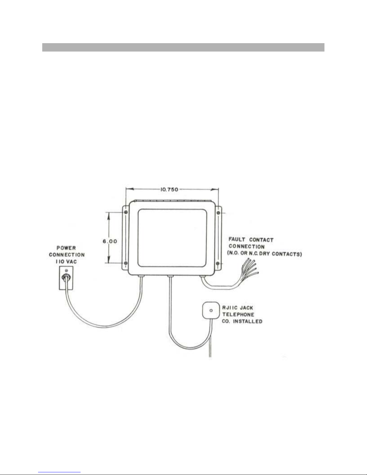
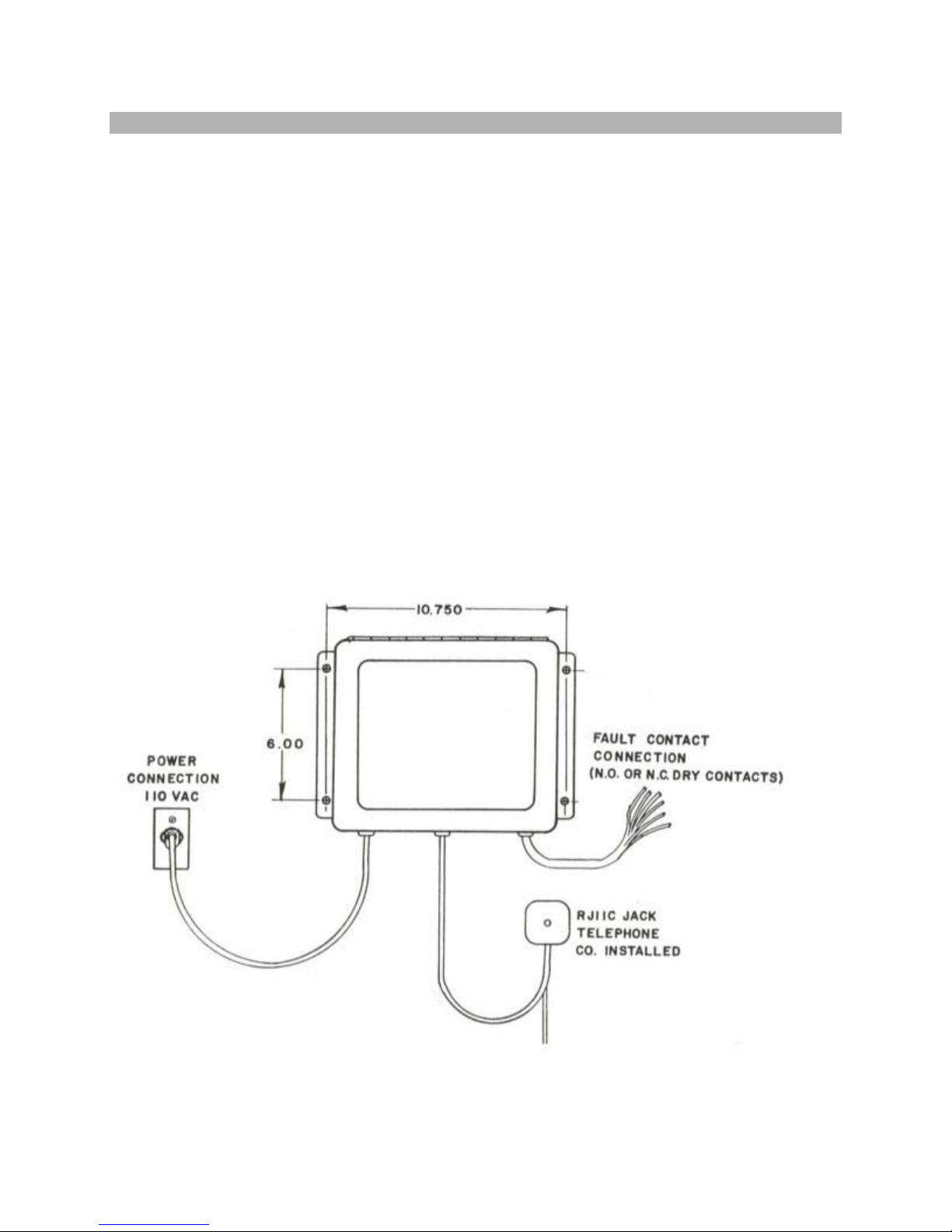
C. PHYSICAL SYSTEM INSTALLATION
Mount the system on a wall or other vertical surface, away from and protected from
harsh weather extremes. It is also recommended that the unit not be placed in close
proximity to high voltage (480 V and higher) electrical equipment. Four mounting
holes on the left and right side enclosure flanges are to be used for system mounting.
It is recommended that the system be mounted approximately 5 feet above surface
grade for proper microphone reception in both the speakerphone and intercom mode.
There are three access holes on the bottom of the unit. The left side port is for power
connection to 120 vac. The middle port is for the system's telephone line connection,
and the right side port is intended to be used for the entry of fault monitoring channel
conductors. There is an additional hole in the bottom of the unit, into which the
speakerphone microphone is mounted.
The following figure shows the recommended dimensions to be used in the physical
Installation of the system.
3
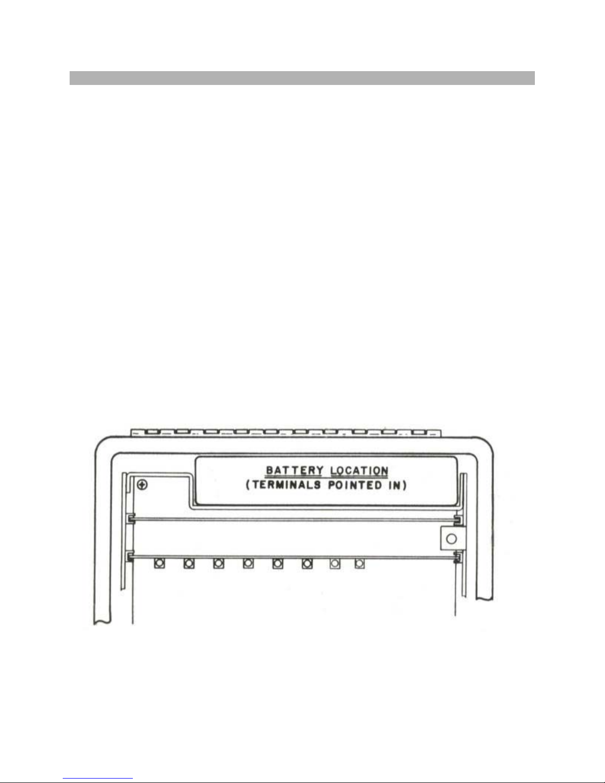
D. BATTERY INSTALLATION
The battery installs at the top of the system, in the battery tray provided as part of the
interior chassis assembly.
It is necessary to remove power from the system if it is currently applied.
REMOVE 120 VAC POWER FROM THE SYSTEM IF YOU HAVE NOT ALREADY
DONE SO
Open the system front panel and retrieve the red and black battery leads from within
the battery tray. Push the battery lead terminals on to the new battery, BEING
CERTAIN that the red lead connects to the positive (+) battery terminal, and the
black lead connects to the negative (-) battery terminal.
Slide (do not force) the battery completely into the battery tray with the TERMINALS
POINTED INTO THE SYSTEM. If the battery is not completely seated in the battery
tray, the front panel will be obstructed and will not completely close.
A new battery will take no longer than 24 hours to gain a full charge, capable of
powering the system through any power outage up to four hours in length. It should
be noted that the LOW BATTERY indicator is only valid when the 120 vac power is
on. If the LOW BATTERY indicator stays on for more than eight hours, the battery is
in need of replacement.
4
E. ELECTRICAL POWER INSTALLATION
Electrical power may be applied by simply plugging the system into a grounded,
three wire outlet. BE CERTAIN THAT THE OUTLET HAS AN ADEQUATE EARTH
GROUND. INSUFFICIENT EARTH GROUND CONNECTIONS CAN HARM THE
UNIT AND PREVENT INTERNAL PROTECTION CIRCUITRY FROM PERFORMING
PROPERLY.
It is recommended that a separate circuit breaker be used with the system.
Remember that when the breaker is on, and the unit is plugged in, 120vac is
contained within the system even though the internal STANDBY/OPERATE switch
may be turned off.
If the unit is to be installed in a location where large or high voltage motors are in use
a power line transient suppressor is recommended to insure that the unit is not
affected by surges and spikes in the 120VAC power to the unit. If such a device is
needed, contact Microtel for assistance.
The internal system fuse is a 1/4 amp fuse (Littlefuse #312.250), or equivalent.
WHEN INSPECTING OR REPLACING THE FUSE, YOU MUST UNPLUG THE
SYSTEM OR THROW THE CIRCUIT BREAKER SUPPLYING POWER TO THE
UNIT.
5
 Loading...