

Page 1

Important: Do not
remove the yellow
stickers from your
scanner until you are
told to do so. You
must install software
before connecting
your scanner.
Installing your Microtek ScanMaker i700
Open your scanner package and check the components. If any component is missing,
call Microtek Customer Service.
1
4
7
6
2
5
3
1. ScanMaker i700 scanner
2. FireWire cable
3. Hi-Speed USB cable (backward
compatible with USB 1.1)
4. Power adapter
5. Power cord
6. EZ-Lock 35mm Filmstrip Holder
Contents
STEP 1: Unpack Contents ............................................................................ 1
STEP 2: Install Software .............................................................................. 2
STEP 3: Unlock Scanner .............................................................................. 3
STEP 4: Connect Scanner ............................................................................ 3
A. Power Connections ....................................................................... 3
B. Computer Connections ................................................................. 4
Scanning Scenarios ....................................................................................... 6
Scanning Regular, Non-Damaged Photos................................................... 7
Scanning Damaged Photos .......................................................................... 8
Scanning Regular, Non-Damaged Film ...................................................... 10
Removing the Black Mat .................................................................. 10
8
9
11
7. EZ-Lock 35mm Slide Holder
8. EZ-Lock 6 x 17 cm (120) Panoramic
Film Holder
9. EZ-Lock 4" x 5" / 6 x 9 cm (120) Film Holder
10.Software CD-ROMs (Microtek & Adobe)
11. Documentation: Includes Start Here
Guide, ScanWizard 5 Quick Reference
Guide, and other inserts
Using the FilmView .......................................................................... 10
A. Using the EZ-Lock 35mm Filmstrip Holder ............................... 11
B. Using the EZ-Lock 35mm Slide Holder ..................................... 13
C. Using the EZ-Lock 6 x 17 cm (120) Panoramic Film Holder .... 14
D. Using the EZ-Lock 4" x 5" / 6 x 9 cm (120) Film Holder ........... 15
Scanning Damaged Film ............................................................................. 16
Getting to Know Your ScanMaker i700 ...................................................... 18
Taking a Closer Look .....................................................................................19
How the Scanner Buttons Work .................................................................. 20
System Requirements ................................................................................. 21
Specifications ............................................................................................... 21
10
Copyright©2004 Microtek International, Inc. http://www.microtek.com
I49-003656 B, June 2004
Page 2

For PC Users
1. Turn on your computer.
2. Place the Microtek CD-ROM into your CD-ROM drive. The Microtek Software
Installer screen should automatically come up.
Note: If the Microtek Software Installer screen does not come up automatically,
double-click the following in succession: “My Computer”; the CD-ROM icon;
and cdsetup.exe to start the installer program.
3. Click each software program in the order that it appears on the screen, and follow
the on-screen instructions to install. Do not turn off your computer during
software installation.
4. Click EXIT on the Microtek Software Installer screen when all the software has
been installed.
5. Place the Adobe CD-ROM into your CD-ROM drive, and install the software.
6. Restart your computer.
For Macintosh Users
1. Turn on your computer.
2. Place the Adobe CD-ROM into your CD-ROM drive, and install the software.
3. Place the Microtek CD-ROM into your CD-ROM drive and install all the
software components.
4. Restart your computer.
Note: After rebooting your computer (PC or Macintosh), the Microtek software will
attempt to locate your scanner on the system. Since this is your first install and you
have not yet connected the scanner, simply ignore the message that appears and
proceed to the next step.
Additional Documentation in the CD-ROM
Additional documentation is provided in the Microtek CD-ROM that contains
ScanWizard 5. If you experience problems with hardware or software, you can open
the file that you wish to view with Adobe Acrobat Reader or your browser, then read or
print the information.
2 ScanMaker i700 Installing and Getting Started
Page 3
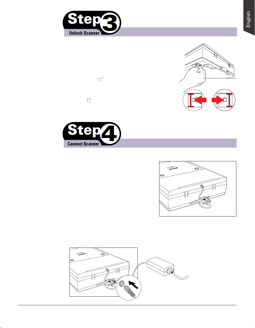
1. Remove the yellow "Step 3" sticker from the scanner.
2. With the scanner power off, tilt the back-left corner
to see the locking switch at the bottom of the scanner.
3. Push the locking switch (red) to the
“Unlocked” ( ) position.
Note: To lock the scanner (for shipping and
other reasons), push the locking switch to the
“Locked” ( ) position. Do not turn the scanner
upside down and attempt to lock the scanner this
way, as this may not work.
A. Power connections
1. Remove the yellow "Step 4" sticker from
the scanner.
2. Check to make sure that the scanner lid
(Light Plate) is properly installed, with its
connector securely connected to the
scanner’s 15-pin accessory port.
Unlocked Locked
3. Connect the power adapter and the power cord.
Plug one end of the power adapter assembly into the back of the scanner, and
plug the other end into a wall outlet or other power source.
Note: Make sure no other cable is
connected to the scanner except the
power cord at this point.
ScanMaker i700 Installing and Getting Started 3
Page 4
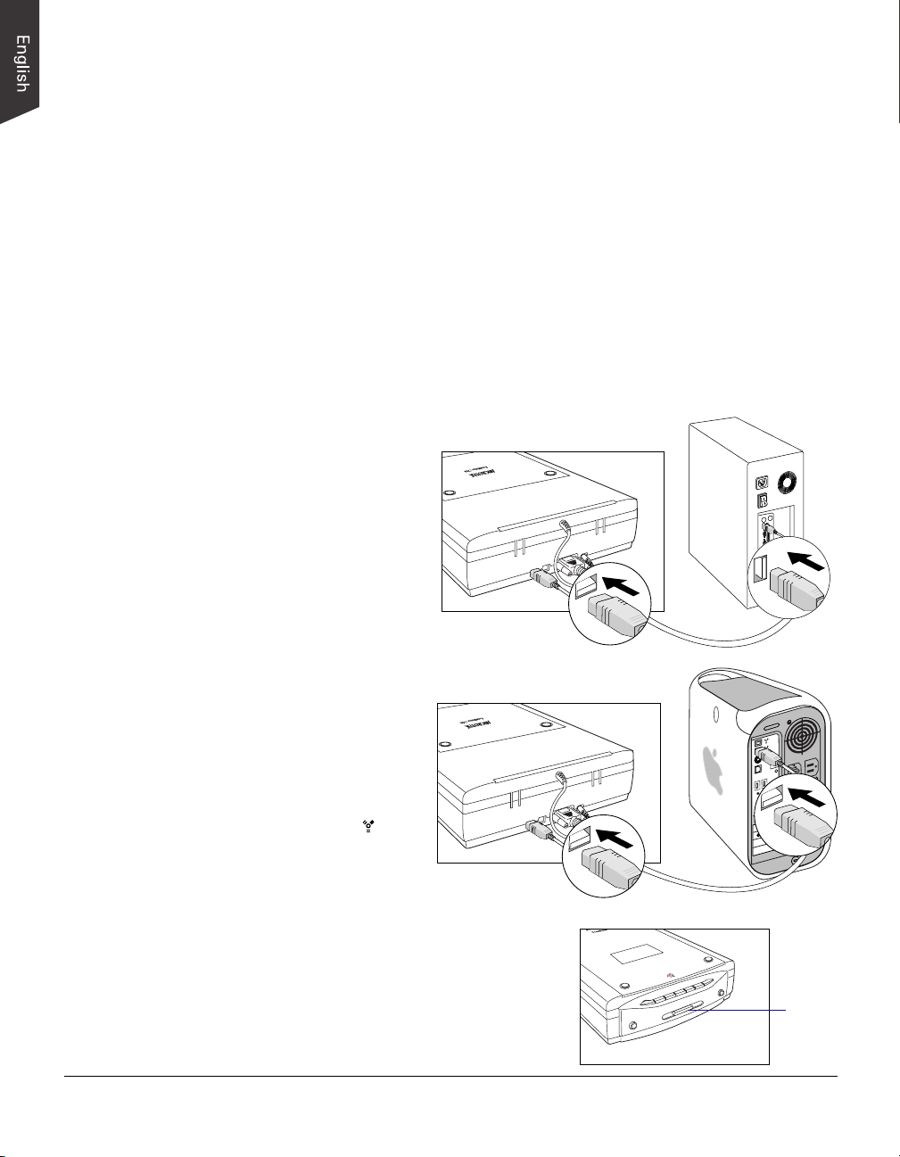
B. Computer connections
The ScanMaker i700 comes with FireWire (IEEE 1394) and Hi-Speed USB interfaces
built-in. You may choose either FireWire or Hi-Speed USB as the interface for
connection between the scanner and computer. (You can use only one interface at a time.)
Using the FireWire Cable
Check first to see if your computer system has a FireWire port. If FireWire is
present, connect the FireWire cable to the FireWire port. If your computer does not
have a FireWire port, install a FireWire card to make use of the FireWire port. For
more details on how to install a FireWire card in your computer, refer to the
documentation that came with your purchased FireWire card.
Follow the steps below to perform the FireWire connection.
1. Connect one end of the FireWire cable to your computer, and connect the other
end of the cable to the scanner’s FireWire port.
(with a built-in FireWire port
For PC users
or FireWire card installed)
For Mac users
(with a built-in FireWire port)
The latest Macintosh
computers (i.e., G3, G4, G5,
etc.) are equipped with a
built-in FireWire port, usually
labeled with the “ ” logo.
2. Press the Power button on the front panel of
the scanner, and wait for the lights to stop
blinking and stay on steady.
The scanner will be detected by your system
automatically.
Power
button
4 ScanMaker i700 Installing and Getting Started
Page 5
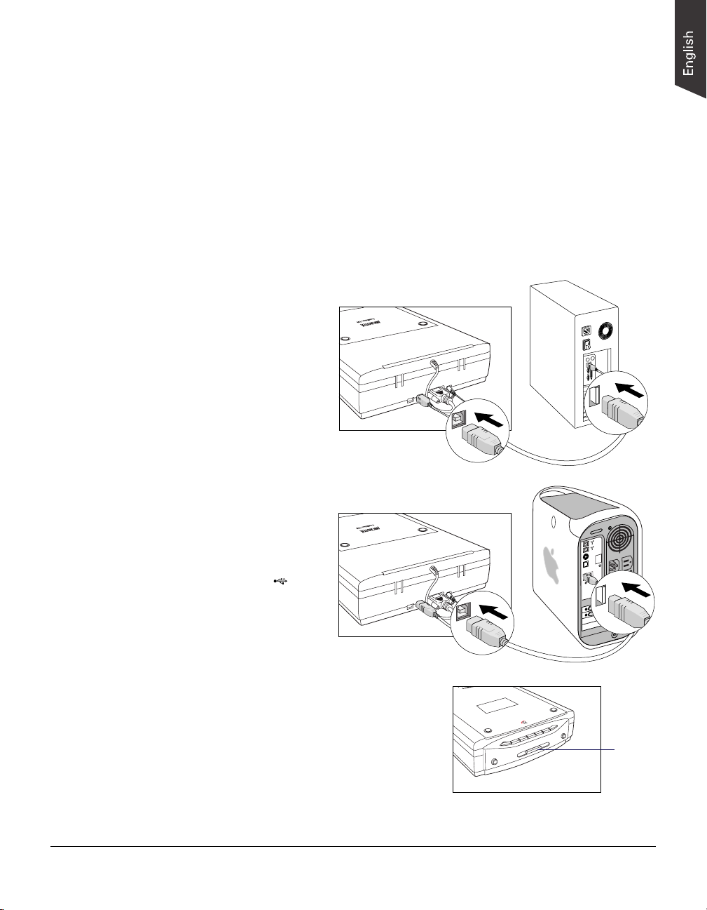
Using the Hi-Speed USB Port
Check first to see if your computer system has Hi-Speed USB or USB 1.1 ports. If
both ports are present, connect the Hi-Speed USB cable to the Hi-Speed USB port
(not to the USB 1.1 port) to obtain faster scanning. If your computer does not have a
Hi-Speed USB port, install a Hi-Speed USB card to make use of the Hi-Speed USB
port; or as an alternative, use the USB 1.1 port instead. For more details on how to
install a Hi-Speed USB card in your computer, please refer to the documentation that
came with your purchased Hi-Speed USB card.
Follow the steps below to make the USB connection.
1. Connect one end of the Hi-Speed USB cable to your computer, and connect the
other end of the cable to the scanner’s USB port.
(with a built-in USB port
For PC users
or a Hi-Speed USB
card installed)
For Mac users
(with a built-in USB port)
USB port usually labeled
with the “ ” logo.
2. Press the Power button on the front panel of
the scanner, and wait for the lights to stop
blinking and stay on steady.
The scanner will be detected by your system
automatically.
Power
button
ScanMaker i700 Installing and Getting Started 5
Page 6

Scanning Scenarios
The following pages provide various scenarios for scanning with the ScanMaker
i700, including the following:
• Scanning regular, non-damaged photos. This scenario can also be your first scan
in order to familiarize yourself with scanning basics, and makes use of the
Standard Control Panel in ScanWizard 5.
• Scanning damaged photos. This scenario makes use of the Advanced Control
Panel in ScanWizard 5, and utilizes DIGITAL ICE for correcting scratches, rips,
and tears that may be present in your photos.
• Scanning regular, non-damaged film. This scenario makes use of the Advanced
Control Panel in ScanWizard 5, and utilizes the various EZ-Lock Film Holders
to scan a variety of film, slides, and transparencies.
• Scanning damaged film. This scenario makes use of the Advanced Control
Panel in ScanWizard 5, and utilizes DIGITAL ICE for correcting flaws that may
be present in your negative and positive film and transparencies.
6 ScanMaker i700 Installing and Getting Started
Page 7
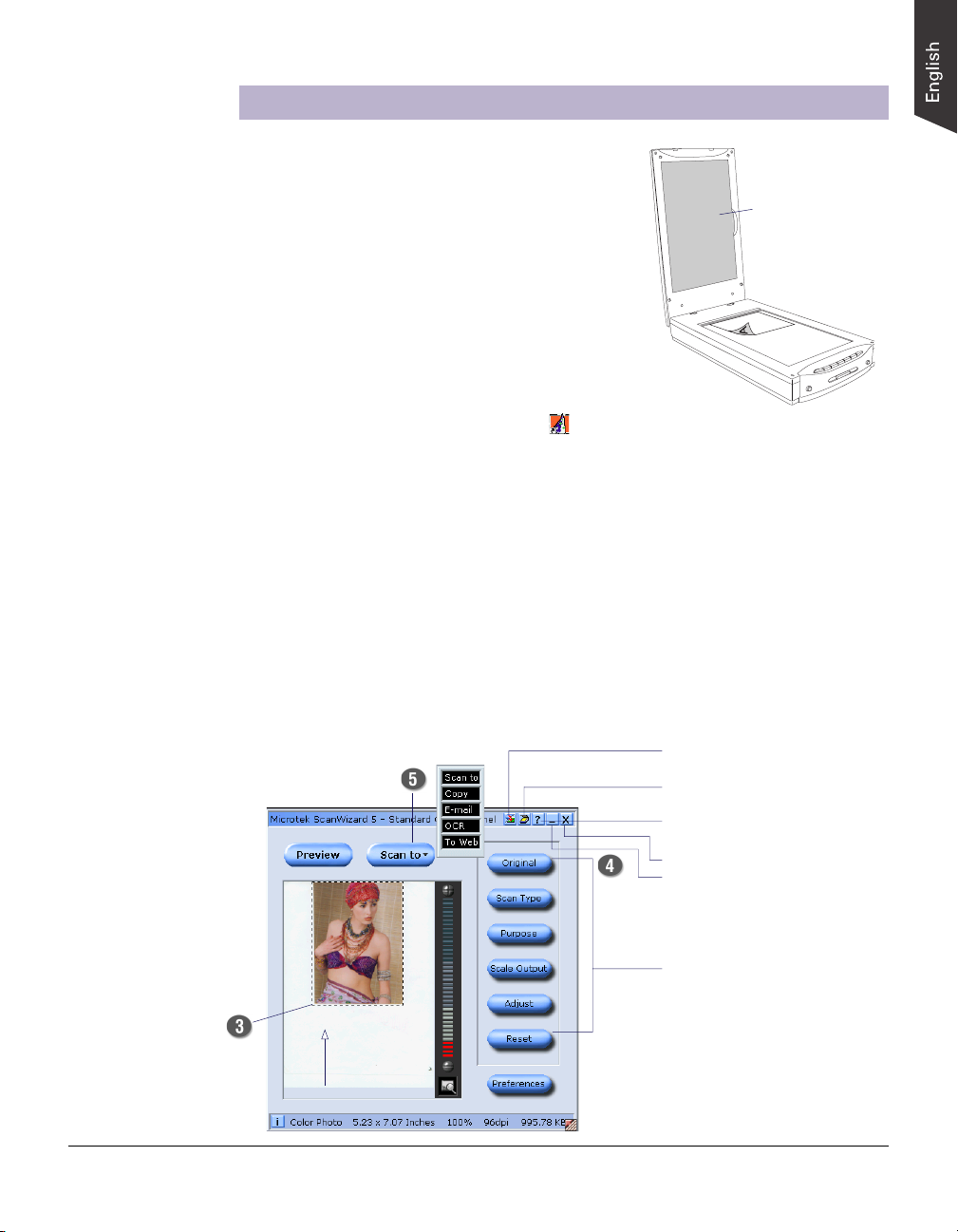
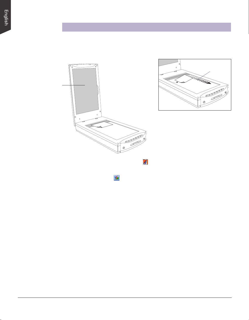
Scanning Regular, Non-Damaged Photos
1. Raise the scanner lid, and place the photo to be
scanned face down on the scanner glass
surface.
The top end of the photo should be positioned
towards the back of the scanner.
Note: To accurately perform an auto-crop
preview of the photo loaded onto the scanner,
make sure the Black Mat is attached on the
scanner lid (Light Plate) before launching
ScanWizard 5.
2. Double-click the ScanWizard 5 icon ( ) on your desktop to launch the
ScanWizard 5 Standard Control Panel.
When ScanWizard 5 launches, it automatically performs a fast preview of the
material on your scanner glass surface and displays it in the preview area.
3. In the preview window, you can resize the scan frame (floating dotted line)
around the image by dragging on the edge or corner of the scan frame to
determine the final size of the actual scan.
4. Click the Original button, then select Photo.
5. Click the Scan to button to scan the image.
After the scan, the scanned and processed image can be saved as a file, opened in
an image-editing program, sent to a printer, attached in an e-mail, or uploaded to
a website.
The Black Mat
comes
preattached to the
scanner lid.
Resize the scan
frame to adjust
the actual size of
your scan
• Allows you to switch to the
Advanced Control Panel
• Shows the scanner type,
model, and status
• Contains the built-in
ScanWizard 5 help
• Exits ScanWizard 5
• Minimizes ScanWizard 5
(Windows only)
Selections and options for
image settings
ScanMaker i700 Installing and Getting Started 7
Page 8
Scanning Damaged Photos
1. Raise the scanner lid, then place the damaged photo to be scanned face down on
the scanner glass surface. Center the top of the photo along the horizontal ruler
towards the back of the scanner.
Make sure the Black
Mat is attached to the
scanner lid. This will
ensure that uneven
photos lay as flat as
possible, which will
enhance the accuracy of
detecting surface
damage on photos.
Direction of
carriage motion
Note: If the creases lie parallel to the
direction of the carriage motion, the
creases may not be detected by the
scanner. To fix this problem, position your
photo slightly skewed (min. 10°, max. 45°),
so that none of the creases are parallel to
the direction of the carriage movement.
2. Double-click the ScanWizard 5 icon ( ) on your desktop to launch the
ScanWizard 5 Standard Control Panel.
3. Click the Switch icon ( ) on the right corner of the Standard Control Panel to
switch to the Advanced Control Panel.
4. Click the Overview button to perform a preliminary view of the entire image.
When done, you will see an image appear in the preview window.
5. In the preview window, you can resize the scan frame (floating dotted line)
around the image by dragging on the edge or corner of the scan frame to
determine the final size of the actual scan.
6. Specify your scanning requirements in the Settings window when the ScanWizard
5 Advanced Control Panel appears.
a) Select RGB Colors/RGB Color (48-bit) or Grayscale/Grayscale (16-bit) in the
Type pull-down menu as your image output type.
b) Select a desired resolution in the Resolution pull-down menu for your image
output resolution. The recommended resolution for DIGITAL ICE for photos
is 600 dpi, and take note that the use of DIGITAL ICE will require additional
time in processing compared to regular scanning.
c) Adjust the scan frame settings if necessary.
8 ScanMaker i700 Installing and Getting Started
Page 9

7. If necessary, adjust image quality using the image corrections tools (White/Black
Points, Tone Curve, Brightness/Contrast, Color Correction, Filter, and Descreen).
Important: The Descreen setting in the Settings window should be “None.”
Otherwise the “DIGITAL ICE” option in the next step will be dimmed and will
not be available for selection.
8. Choose the DIGITAL ICE option that
works best for you. Select from None,
Automatic Reconstruction, or Manual
Reconstruction. In Reflective mode,
DIGITAL ICE automatically removes
surface defects from your photos.
Note: To apply DIGITAL ICE settings automatically, choose the Automatic
Reconstruction setting. The Manual Reconstruction setting is a more advanced
procedure, and for more details, please refer to the ScanWizard 5 Online Help
feature.
9. If the colors in your photo are faded and need restoring, check the “Automatic
Color Restoration” box in the Settings window.
10.Click the Scan to button to scan the image. After the scan, defects such as dust,
scratches, cracks, creases, rips, folds and other artifacts on the original image
are all removed, resulting in an improved image.
Depending on your selection, the scanned and processed image can be saved to a
file, opened in an image-editing program, sent to a printer, attached in an email, or uploaded to a website.
Before
After
ScanMaker i700 Installing and Getting Started 9
Page 10

Scanning Regular, Non-Damaged Film
The ScanMaker i700 allows you to perform auto-crop scanning on film such as
35mm slides, 35mm filmstrips, 6 x 9 cm (120) film, 6 x 17 cm (120) panoramic film,
and 4" x 5" film.
To scan various film sizes, you will need to use the holder that correctly matches the
film type to be scanned. Included in the scanner package are four EZ-Lock film
holders: EZ-Lock 35mm Slide Holder; EZ-Lock 35mm Filmstrip Holder; EZ-Lock 6
x 17 cm (120) Panoramic Film Holder; and EZ-Lock 4" x 5" / 6 x 9 cm (120) Film
Holder.
Before performing film scanning with the EZ-Lock Film Holders, take note of the
information presented in the two sections below.
Removing the Black Mat
The Black Mat is designed to work with
reflective originals such as photos and printed
matter. It is not designed to work with slides,
negatives, and transparencies. During film
scanning, the Black Mat should be removed to
the reveal light source for film.
To remove the Black Mat: Raise the scanner
lid, and push to the side (1 in diagram) to
remove it from the scanner lid (2 in diagram).
Using the FilmView
The FilmView, a clear window located on the
top of the scanner lid (Light Plate), is designed
for previewing film or slides before they are
loaded onto the scanner bed. The FilmView
adds to your convenience in the selection and
verification of slides or film for scanning.
To select the film you wish to scan, make sure
that the FilmView is on, then place the film you wish to scan on the top of the
scanner lid (Light Plate), using the light source provided by the FilmView to preview
your film.
Note: If the light source of the FilmView is in the “Sleep” mode, press the scanner's
Custom button to exit or halt sleep mode. For more details on the Custom button, see
the online help of the Microtek Scanner Configuration (MSC).
To run auto-crop, the following conditions should all be met:
• The operating system is either Windows or Mac OS X.
• The correct EZ-Lock film holder is loaded and correctly aligned on the scanner surface.
• The scan material is Positive or Negative Film.
• In the Scan Job Queue window, the “Multiple Auto-crop for EZ-Lock Film Holder”
option is checked.
10 ScanMaker i700 Installing and Getting Started
Page 11

To make sure the auto
multiframe cropping
feature performs
correctly, align the
holder’s front edges
flush against the top
ruler of the scanner.
A. Using the EZ-Lock 35mm Filmstrip Holder
The EZ-Lock 35mm Filmstrip Holder can simultaneously hold two strips of 6 frames
each, or a total of 12 frames.
1. Load the filmstrip face down inside the holder. Slide the filmstrip along the slots
of the holder until the filmstrip is fully loaded.
Align the frame-by-frame partition
with the dash marks on the film
guide.
For a short filmstrip, make sure the
film edge is close to the open end of
the slot.
2. Raise the scanner lid, then place the holder with the loaded film on the scanner
glass surface, as shown in the illustration.
The calibration window on the glass
surface should be kept clear and free
from any obstruction during scanning.
3. Gently lower the scanner lid down onto the scanner glass surface; the lid should
be able to close completely.
4. Double-click the ScanWizard 5 icon ( ) on your desktop to launch the
ScanWizard 5 Standard Control Panel, then click the Switch icon ( )on the right
corner of the Standard Control Panel to switch to the Advanced Control Panel.
5. Click the Scan Material button
( ), and choose Negative Film.
For Mac OS X, select Negative
from the Scan Material drop-down
menu.
ScanMaker i700 Installing and Getting Started 11
Page 12

6. Check the “Multiple Auto-crop for EZ Lock Film Holder” option in the Scan Job
Queue window.
7. Click the Overview button to auto-crop and perform a preview of the film loaded
onto the scanner.
When done, you will see multiple scan frames that have been automatically
cropped in the preview window. Multiple job titles will appear in the Scan Job
Queue window, numbered sequentially and all marked by a “Check” that
indicates the jobs are ready to be scanned. The scan area (framed in dotted lines)
will appear in the Preview window. Maximum scanning range is 9" x 4".
Auto-cropped images are
framed in dotted line.
8. Specify your scanning parameters in the Settings window.
9. Click the Scan to button to scan all the checked jobs.
10. After the scan, the scanned and processed images can be saved as several files,
opened in an image-editing program, sent to a printer, attached in an e-mail, or
uploaded to a website.
12 ScanMaker i700 Installing and Getting Started
Page 13

To make sure the auto
multiframe cropping
feature performs
correctly, align the
holder’s front edges
flush against the top
ruler of the scanner.
B. Using the EZ-Lock 35mm Slide Holder
The EZ-Lock 35mm Slide Holder can simultaneously hold up to 8 mounted 35mm
slides at a time.
1. Flip the 35mm slides face
down and place them into the
holder.
2. Raise the scanner lid, then place the holder with the loaded film on the scanner
glass surface as shown in the illustration.
1
5
6
2
3
7
8
4
The calibration window on the glass
surface should be kept clear and free
from any obstruction during scanning.
3. Follow the procedures (steps 3 through 10) for scanning 35mm filmstrips to
carry out scanning. Before performing step 5, click the Scan Material icon, and
choose “Positive Film”; for Mac OS X, select “Positive” from the Scan Material
drop-down menu.
ScanMaker i700 Installing and Getting Started 13
Page 14

C. Using the EZ-Lock 6 x 17 cm (120) Panoramic Film
Holder
The EZ-Lock 6 x 17 cm (120) Panoramic Film Holder can hold 1 piece of 120
panoramic film or a variety of various-sized film, such as 4 pieces of 6 x 4.5 cm film,
or 2 pieces each of 6 x 6 cm film, 6 x 7 cm film, and 6 x 9 cm film.
1. Load the film face down inside the holder.
a) Push on the side to open the lid.
b) Place the film face down into the holder.
c) Pull down the side to close the lid.
2. Raise the scanner lid, then place the holder with the loaded film on the scanner
glass surface as shown in the illustration.
To make sure the auto
multiframe cropping
feature performs
correctly, align the
holder’s front edges
flush against the top
ruler of the scanner.
3. Follow the procedures (steps 3 through 10) for scanning 35mm filmstrips to carry
out scanning.
14 ScanMaker i700 Installing and Getting Started
The calibration window on the glass
surface should be kept clear and free
from any obstruction during scanning.
Page 15

To make sure the auto
multiframe cropping
feature performs
correctly, align the
holder’s front edges
flush against the top
ruler of the scanner.
D. Using the EZ-Lock 4" x 5" / 6 x 9 cm (120) Film
Holder
The EZ-Lock 4" x 5" / 6 x 9 cm (120) Film Holder can hold 1 piece of 4" x 5" film.
It can also hold different sizes of 120 film, such as 2 pieces of 6 x 4.5 cm film, or 1
piece each of 6 x 6 cm film, 6 x 7 cm film, and 6 x 9 cm film.
1. Load the film face down inside the
holder. Slide the film along the slots of
the holder until the film is fully loaded.
2. Raise the scanner lid, then place the holder with the loaded film on the scanner
glass surface as shown in the illustration.
The calibration window on the glass
surface should be kept clear and free
from any obstruction during scanning.
3. Follow the procedures (steps 3 through 10) for scanning 35mm filmstrips to carry
out scanning.
ScanMaker i700 Installing and Getting Started 15
Page 16

Scanning Damaged Film
1. Raise the scanner lid, then place the
holder with the loaded film on the scanner
glass surface.
Follow the procedures for using the EZLock Film Holders in the previous sections
to load the film that you wish to scan.
Gently lower the scanner lid down onto
the scanner's glass surface.
2. Double-click the ScanWizard 5 icon ( ) on your desktop to launch the
ScanWizard 5 Standard Control Panel, then click the Switch icon ( )on the right
corner of the Standard Control Panel to switch to the Advanced Control Panel.
3. In the Preview window, click the
Scan Material button or dropdown menu. Choose Negative Film
or Negative for negatives; choose
Positive Film or Positive for
transparencies and slides,
depending on the film type you are
using.
4. In the Scan Job Queue window, check the “Multiple Auto-crop for EZ Lock Film
Holder” option.
5. Click the Overview button to auto-crop and perform a preview of the film loaded
onto the scanner.
When done, you will see multiple scan frames that have been automatically
cropped in the preview window. Multiple job titles will appear in the Scan Job
Queue window, numbered sequentially and all marked by a “Check” that
indicates the jobs are ready to be scanned. The scan area (framed in dotted lines)
will appear in the Preview window. Maximum scanning range is 9" x 4".
6. Specify your scanning requirements in the Settings window.
a) Select RGB Colors/RGB Color (48-bit) or Grayscale/Grayscale (16-bit) in the
Type pull-down menu as your image output type.
b) Select a desired resolution in the Resolution pull-down menu for your image
output resolution. The recommended resolution for DIGITAL ICE is 1200 dpi,
and take note that using DIGITAL ICE will require more time than regular
scanning.
c) Adjust the scan frame settings if necessary.
16 ScanMaker i700 Installing and Getting Started
Page 17

7. If necessary, adjust image quality using the image corrections tools (White/Black
Points, Tone Curve, Brightness/Contrast, Color Correction, and Filter).
8. Choose the “DIGITAL ICE” option that
works best for you. Select from None,
Normal, or Strong. In Film mode,
DIGITAL ICE automatically removes
surface defects from your slides,
negatives, and transparencies.
9. If the colors in your film sample are faded and need restoring, check the
“Automatic Color Restoration” box in the Settings window.
10.Click the Scan to button to scan the image. After the scan, defects such as dust,
scratches, cracks, creases, rips, folds and other artifacts on the original image
are all removed, resulting in an improved image.
Depending on your selection, the scanned and processed image can be saved to a
file, opened in an image-editing program, sent to a printer, attached in an e-mail,
or uploaded to a website.
Before
After
ScanMaker i700 Installing and Getting Started 17
Page 18

Getting to Know Your ScanMaker i700
The ScanMaker i700 is a high-performance scanner that features robust film
handling capabilities and cutting-edge DIGITAL ICE technology for both photos and
film. It features 48-bit color, 9600 x 4800-dpi optical resolution, legal size scan bed
(8.5" x 14"), and is equipped with 7 Smart-Touch buttons on the front panel for easy
access to scanner functions.
In addition, the ScanMaker i700 comes with specially designed EZ-Lock Film
Holders — exclusive film accessories from Microtek that lock film securely into
place on the scan bed to ensure perfect alignment and consistent scans.
Other important features of the ScanMaker i700 include:
• Microtek's PictuRescueTM system — a combined photo and film reconstruction
and restoration solution that incorporates DIGITAL ICETM Technology and
ColoRescueTM.
– With DIGITAL ICE Technology, the ScanMaker i700 can automatically map,
identify, and eliminate surface defects on photos and film. Built into the
hardware and software, DIGITAL ICE removes dust, scratches, and rips,
bringing damaged photos and film back to pristine, near-original quality.
– ColoRescue is an automatic color recovery and control process that brings
faded colors back to life for more vibrant images.
• An integrated 4" x 9" transparency adapter (Light Plate) that lets you scan slides,
transparencies, and negative film. There is no need to purchase additional
accessories such as a Transparent Media Adapter. The Light Plate has a built-in
FilmView feature — a clear window with a light source that lets you preview film
or slides before they are loaded onto the scanner glass bed.
• The Smart-Touch buttons (DIGITAL ICE, Scan, Copy, E-mail, OCR, Scan-toWeb, and Custom), which provide you with an easy and intuitive way to access
frequently used scanner functions.
18 ScanMaker i700 Installing and Getting Started
Page 19

Horizontal ruler
(top ruler)
Taking a Closer Look
Black mat
Glass surface
Vertical ruler
FilmView
Scanner lid
(Light Plate)
Custom
Scan-to-Web
OCR
Power button
E-mail
Copy
Scan
DIGITAL ICE
Power connector
Accessory port with Light
Plate's connector securely
connected
Hi-Speed USB port (1)
FireWire port (1)
ScanMaker i700 Installing and Getting Started 19
Page 20

How the Scanner Buttons Work
Note: The parameters for each Smart-Touch scanner button are defined or set
through the Microtek Scanner Configuration (MSC) utility. For instance, you can use
the MSC to define how many copies are to be printed of your scan every time you hit
the "Copy" button. To launch the MSC, double-click the MSC icon on your desktop.
Please note that you need to exit ScanWizard 5 before accessing the MSC utility.
The ScanMaker i700 is equipped with 7 Smart-Touch buttons for easy access to
frequently used scanner functions. The Smart-Touch buttons are DIGITAL ICE,
Scan, Copy, E-mail, OCR, Scan-to-Web, and Custom. To carry out a specific task,
simply press the corresponding button on the scanner.
• DIGITAL ICE: Scans and removes dust, scratches, rips, and tears from damaged
photos. Important: The DIGITAL ICE button works only on photos. To repair
damaged film and transparencies, use the DIGITAL ICE function in the
ScanWizard software.
• Scan: Captures high-resolution images with outstanding quality that can be
automatically saved as files or sent to another application for further processing.
• Copy: Scans the image and sends it to your printer, transforming your scanner and
printer into a convenient copy station. Simply specify the number of copies you
want.
How to use the Copy button to print a stack of documents:
1. Place the first page on the scanner glass surface.
2. Press the Copy button to scan an image to a file, then automatically output to
your specified printer.
3. Load the next page and press the Copy button again. The scanner works in
similar fashion to your printer, printing documents one after another with no
interruptions.
• E-mail: Scans the image and delivers it directly to your e-mail editor.
• OCR: Performs OCR (Optical Character Recognition) of a document and converts
it to a fully editable digital file. Saves time from retyping documents into your
word processor.
• Scan-to-Web: Scans the image and posts it instantly onto a photo-sharing website.
• Custom: Customizes the four most commonly used functions.
- Power Saving: Turns the scanner lamp ON or OFF to save power and lamp life.
- Scan: Defines another button to be a second “Scan” button. Use this if you need a
second “Scan” button with different parameters from the first Scan button.
- Fax: Launches a fax driver installed in your computer.
- Launch Application: Defines an application to be launched.
20 ScanMaker i700 Installing and Getting Started
Page 21

System Requirements
• CD-ROM drive (for installing software)
• Color display with 24-bit color output capability
• 128MB RAM (256MB or more to use DIGITAL ICE Technology)
PC and compatibles
• Pentium III PC or higher with USB, Hi-Speed USB (USB 2.0), or FireWire
(IEEE 1394) port
• Microsoft Windows 98SE, Me, 2000 or XP
Macintosh
• iMac or Mac G3/G4/G5 with built-in USB port or FireWire port
• Mac OS 9.x, Mac OS X 10.2, 10.3 or later
Specifications
Scanning Modes Color, grayscale, and black-and-white in a single
scanning pass
True 48-bit color (approx. 281 x 1012 colors)
16-bit grayscale (approx. 65,536 shades of gray)
Scanning Area Reflective: 8.5" x 14" (216 mm x 356 mm)
Transparent: 4" x 9" (102 mm x 229 mm)
Resolution Optical: 9600 dpi x 4800 dpi
Interpolated: 65,535 dpi (PC); 32,767 dpi (Mac)
Interface Hi-Speed USB (USB 2.0) and FireWire (IEEE 1394)
Dimensions (L x W x H) 21.5" x 11.7" x 3.6" (545 mm x 297 mm x 92 mm)
Net Weight 11.9 lbs (5.4 kg)
Voltage AC 100V to 240V
1.2A Max; 47-63 Hz (Input)
15V/2.5A (Output)
Environment Operating Temperature: 50° F to 104° F (10° C to 40° C )
Power supply Manufacturer Model No. Voltage
(AC/DC adapter) FAIRWAY VE50-150A 100V to 240V
ScanMaker i700 Installing and Getting Started 21
Page 22

22 ScanMaker i700 Installing and Getting Started
Page 23

Energy Star Notice
As an ENERGY STAR Partner,
Microtek International, Inc.
has determined that this
scanner meets the ENERGY
STAR guidelines for energy
efficiency.
Trademarks
Microtek®, ScanMakerTM,
and ScanWizard® are
trademarks or registered
trademarks of Microtek
International, Inc. DIGITAL
ICE is a trademark of Kodak.
Macintosh® and Apple® are
registered trademarks of
Apple Computer, Inc.
Windows® is a registered
trademark of Microsoft
Corporation. All other
products or name brands
are trademarks of their
respective holders.
Important
Documents you scan may
be protected under
copyright law. The
unauthorized use of such
documents could be a
violation of the rights of the
copyright holder. Microtek
bears no responsibility for
the unauthorized use of
copyrighted materials.
Federal Communications Commission Interference
Statement
This equipment (Model: MRS-9600FU2) has been tested and found to comply with
the limits for a Class B digital device, pursuant to Part 15 of the FCC rules. These
limits are designed to provide reasonable protection against harmful interference in a
residential installation. This equipment generates, uses and can radiate radio
frequency energy and, if not installed and used in accordance with the instructions,
may cause harmful interference to radio communications. However, there is no
guarantee that interference will not occur in a particular installation. If this equipment
does cause harmful interference to radio or television reception, which can be
determined by turning the equipment off and on, the user is encouraged to try to
correct the interference by one or more of the following measures:
• Reorient or relocate the receiving antenna.
• Increase the separation between the equipment and receiver.
• Connect the equipment into an outlet on a circuit different from that to which the
receiver is connected.
• Consult the dealer or an experienced radio/TV technician for help.
Note: A shielded Hi-Speed USB interface cable with ferrite core installed on the
scanner connector end must be used with this equipment.
Caution: Changes or modifications not expressly approved by the manufacturer
responsible for compliance could void the user's authority to operate the equipment.
This device complies with Part 15 of the FCC Rules. Operation is subject to the
following two conditions: (1) This device may not cause harmful interference, and
(2) this device must accept any interference received, including interference that may
cause undesired operation.
Responsible Party: Loi Han
Microtek Lab, Inc.
16941 Keegan Avenue
Carson, CA 90746
USA
Phone: 310-687-5800
Fax: 310-687-5950
ScanMaker i700 Installing and Getting Started 23
Page 24

24 ScanMaker i700 Installing and Getting Started
 Loading...