

Page 1
Installing and
Getting Started
for the ScanMaker
Installation for PC and Macintosh
®
8700
Version
Version
FireWire - Windows 98 SE, Windows Me,
Windows 2000, Mac G3/G4 and iMac DV
USB - Windows 98, Windows Me,
Windows 2000, Mac G3/G4 and iMac
1. Unpack scanner
Open your scanner package and check major components
as shown in this section. For a complete listing of
components, refer to the Packing List. If any item is
missing, contact Microtek Customer Service.
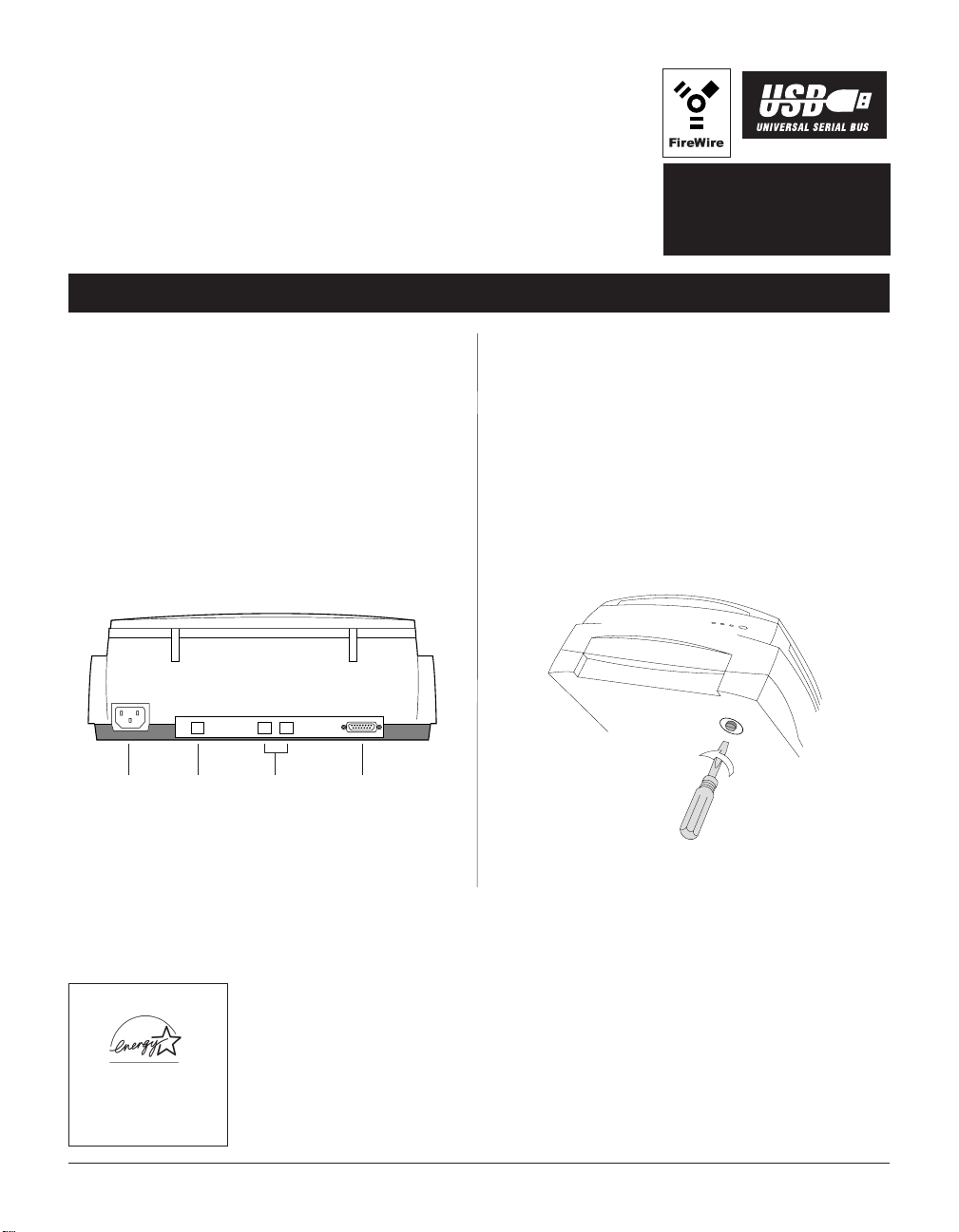
Your Micr otek ScanMaker 8700 scanner comes with
FireWire FireWire
FireWire and
FireWire FireWire
below to locate the different ports on the back of the
scanner, including the scanner's ADF port.
connector
USB USB
USB built-in interfaces. See the graphic
USB USB
USB portPower
FireWire
connector
ADF port
2.Unlock the carriage
With the scanner turned off, unlock the carriage by using a
screwdriver or a coin into the locking screw located at the
bottom of the scanner.
T urn the locking scr ew counterclockwise to unlock it.
When successfully unlocked, the screw will push out a
little, becoming nearly even with the back of the scanner.
This indicates the scanner carriage has been released, and
the scanner is ready to be used.
Energy Star Notice
As an ENERGY STAR Partner,
Microtek International, Inc. has
determined that this scanner
meets the ENERGY STAR
guidelines for energy efficiency .
Copyright © 2000 Microtek International Inc.
Trademarks
Microtek®, ScanMaker®, and ScanWizard® are registered trademarks of Microtek International Inc. Adobe®, Acrobat®, and PhotoDeluxeTM are
trademarks or registered trademarks of Adobe Systems Incorporated. Caere®, OmniPage®, and PageKeeper® are registered trademarks of Caere
Corporation. Tr ellixTM and Tr ellix W ebTM are trademarks of T rellix Corporation. Ulead® and PhotoImpact® are registered trademarks of Ulead
Systems, Inc. Macintosh®, Apple®, FireWire® and FireWire logo are trademarks or registered trademarks of Apple Computer, Inc.
Windows® is a registered trademark of Microsoft Corporation. All other products or name brands are trademarks of their respective holders.
http://www.microtek.com
I49-002852B, August 2000
Page 2

3. Install software
For PC Users
1. T urn on your computer .
2. Insert the Microtek CD-ROM into your CD-ROM
drive. This includes your scanner controller program
for capturing images from your scanner . The Microtek
Software Installer screen should automatically come
up.
Note: If the Microtek Software Installer screen does not
come up automatically, double-click the following in
succession: “My Computer” on your Windows desktop; the
CD-ROM icon; and cdsetup.exe to start the installer
program.
3. When the Microtek Software Installer screen appears,
click each software program in the order that it appears
on the screen to install all software components. (Y our
software includes programs for image editing, OCR
text editing, document management, and the Adobe
Acrobat Reader program for reading documentation).
For each software, follow the on-screen instructions
during installation. Default values are specified at every
point during installation; simply accept these values to
continue installation until you finish.
Note: You may be prompted to restart the computer at this
point. Do not restart your computer until all the software
has been installed.
For Macintosh Users
1. Turn on your computer .
2. Install the image-editing software, which is a separate
CD-ROM included with your scanner package.
3. Install all the software on your Microtek
CD-ROM. T o install each software, open the software
program's folder , and then click the “Installer” icon.
Follow the screen instructions until installation is
completed.
• Microtek ScanWizard 5 is the scanner controller
program for capturing images from your scanner
and delivering it to your image-editing application.
Note: For iMac users, please visit Apple’s web site at
http:// www.apple.com to download and install any
iMac updates you may need.
• Install the software documentation reader for
reading and printing the manuals on the CD-ROM.
4. Restart your computer .
In some applications, auxiliary information (such as the
Readme file) may be displayed after that particular
program finishes installing. Simply click the “X” close
box at the upper right corner of the displayed window
to return to the Microtek Software Installer .
4. After all the software has been installed, click
EXITEXIT
EXIT on
EXITEXIT
the Microtek Software Installer screen
5. If any other image-editing software is bundled with
your scanner, install them now.
Note: The software may be on a separate CD-ROM.
6. Restart your computer .
2
Page 3
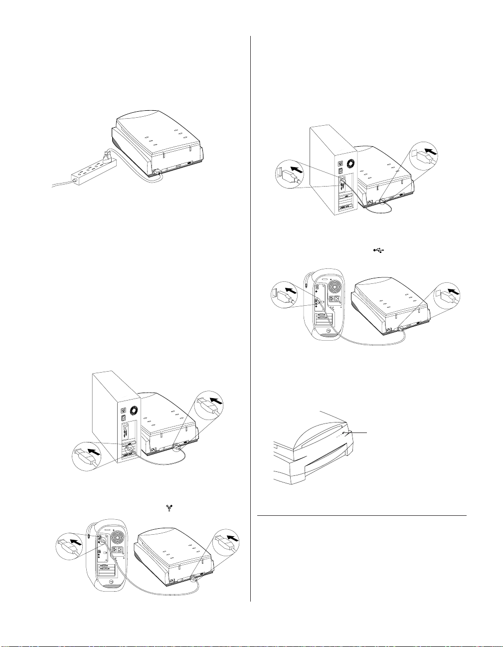
4. Connect scanner
1. Plug the power cord into the back of the scanner , and
plug the other end into a wall outlet or power source.
Make sure no other cable is connected to theMake sure no other cable is connected to the
Make sure no other cable is connected to the
Make sure no other cable is connected to theMake sure no other cable is connected to the
scanner except the power cord at this pointscanner except the power cord at this point
scanner except the power cord at this point.
scanner except the power cord at this pointscanner except the power cord at this point
2. Connect either the
computer and scanner. (
interface at a time.interface at a time.
interface at a time.)
interface at a time.interface at a time.
A. FireWire cable connections
FireWireFireWire
FireWire or the
FireWireFireWire
YY
ou can use only oneou can use only one
Y
ou can use only one
YY
ou can use only oneou can use only one
USB cableUSB cable
USB cable to your
USB cableUSB cable
If your system is FireWire-ready, connect one end of
the FireWire cable to your computer , and connect the
other end of the cable to the scanner's FireWire
connector (either one is applicable).
If your system is not FireWire-ready, you will need to
install a FireWire card. For more details on how to
install the FireWire card, please refer to the FireWire
Installation Guide on a separate sheet included with the
FireWire card.
PC
B . USB cable connections
Connect one end of the USB cable to your computer,
and connect the other end of the cable to the scanner’ s
USB port.
PC
Mac
Before connecting, plug the cable connector into the
computer’s port labeled USB “ ” logo.
3. Press the scanner’s power button to turn on your
scanner.
Mac
Before connecting, plug the cable connector into the
computer’s port labeled FireWire “ ” logo.
The green light on the front of the scanner will blink for
a few seconds and then stay on solid.
Power button
Press the scanner’s
power button to turn
the scanner on/off.
4. The system will detect your scanner automatically.
ImportantImportant
Important
ImportantImportant
Notes:Notes:
Notes:
Notes:Notes:
1. If the system encounters problems other than Item 2
TT
below, see the Troubleshooting file in the
echinfoechinfo
T
echinfo folder
TT
echinfoechinfo
on your Microtek CD-ROM.
2. For users who are currently using
Windows 98 SEWindows 98 SE
Windows 98 SE, it is compulsory to follow the
Windows 98 SEWindows 98 SE
FireWire interfaceFireWire interface
FireWire interface on
FireWire interfaceFireWire interface
supplementary steps as described on the next page.
3
Page 4

Supplementary steps to
activate your FireWire scanner
on Windows 98 SE
4. A series of dialog boxes will appear one at a time -follow the instructions on the screen as shown below ,
and then click
Next Next
Next respectively.
Next Next
1. Open the
System PropertiesSystem Properties
System Properties dialog box by doing the
System PropertiesSystem Properties
following in succession:
PanelPanel
Panel, and then double-click the
PanelPanel
2. From the
Manager Manager
Manager tab, then double-click
Manager Manager
Device Device
Device to open its
Device Device
3. On the
System PropertiesSystem Properties
System Properties, select the
System PropertiesSystem Properties
Device properties Device properties
Device properties dialog box.
Device properties Device properties
Driver Driver
Driver tab, click the
Driver Driver
StartStart
SettingsSettings
Start,
Settings,
StartStart
SettingsSettings
Reinstall Driver Reinstall Driver
Reinstall Driver button.
Reinstall Driver Reinstall Driver
ControlControl
Control
ControlControl
System System
System icon.
System System
DeviceDevice
Device
DeviceDevice
[?] IEEE 1394 SBP2[?] IEEE 1394 SBP2
[?] IEEE 1394 SBP2
[?] IEEE 1394 SBP2[?] IEEE 1394 SBP2
BrowseBrowse
Click
Browse
BrowseBrowse
to locate
C:\WINDOWS\INF,
and then
Next Next
click
Next (where
Next Next
C:\WINDOWS is
your system folder).
5. When the driver has been successfully updated, a dialog
box will prompt this message: “
finished installing an updated driver for yourfinished installing an updated driver for your
finished installing an updated driver for your
finished installing an updated driver for yourfinished installing an updated driver for your
hardware devicehardware device
hardware device”. Open the
hardware devicehardware device
Device ManagerDevice Manager
Device Manager dialog box (Step 1 and 2), then click
Device ManagerDevice Manager
the plus (+) sign adjacent to the
Windows hasWindows has
Windows has
Windows hasWindows has
System PropertiesSystem Properties
System Properties -
System PropertiesSystem Properties
Imaging Device. Imaging Device.
Imaging Device. Th e
Imaging Device. Imaging Device.
scanner name and model appears on the list -- this
means that Windows has detected and re-installed your
device successfully .
4
Page 5

5.Scanning an image
To scan photos:
1. Position the photo to be scanned
on the scanner bed.
2. Double-click the
icon on your desktop to launch
the ScanWizard 5 - Standard
Control Panel. When ScanWizard
5 launches, it automatically
performs a fast preview of the material and displays it
in the preview area.
3. In the preview window, you can resize the scan frame
(floating dotted line) around the image by dragging on
the edge or corner of the scan frame to determine the
final size of the actual scan.
4. Click the
Photo.
5. To scan the image, click the Scan to button. The image
is then scanned and saved to a file. Aside from saving,
you may also deliver the scanned image to an imageediting software, an e-mail editor, or a web br owser .
ScanWizard 5ScanWizard 5
ScanWizard 5
ScanWizard 5ScanWizard 5
Original Original
Original button, then select
Original Original
T o scan slides and filmstrips:
1. T o scan slides or filmstrips, you will need to install an
accessory like the 8" x 10" Glass Film Holder, the Main
Staging Template, the 35mm Mounted Film Template,
etc. Refer to a separate document on how to install the
accessories. Here is a sample to install the Glass Holder
for scanning.
a) Place the film on top of the Glass Film Holder, then
place the vinyl strip on the edges outside the film
to secure the film to the holder .
b) Install the Glass Film
Holder by gently
pushing the
transparency tray
back in.
2. Follow (Steps 2, 3, and 5) the
procedures in scanning a photo.
Step 4, select Positive (for scanning
slides) and Negative
(for scanning negative film).
For
ScanWizard 5
for
Windows
Note: For more details on scanning, please refer to
Microtek’s Step-by-Step Tutorial guide included in your
package.
Save the scanned image to a file, or deliver it to an
image-editing program, an e-mail editor, or a web browser.
Click on this button to switch to the
Advanced Control Panel window
Click here to
exit ScanWizard 5
Tool
buttons
for image
settings
Re-size dotted line for size of the actual scan
5
ScanWizard 5
for
Macintosh
Tool
buttons
for image
settings
Page 6

6.How to use the OCR feature in ScanWizard 5
Optical Character Recognition (OCR) is an application that converts scanned documents into
text that can be edited from your word processing program.
1. Place a text document to be scanned on the scanner
bed, then launch ScanWizard 5.
2. Click the following buttons and select the following
options if you are scanning a black & white text
document for OCR purposes:
OriginalOriginal
Original:
OriginalOriginal
Scan TScan T
Scan T
Scan TScan T
Select
T ext Document .
ypeype
ype: Only Black & White
ypeype
option is available if
you selected T ext Document as your Original (previous
step).
3. Click the Scan to
button, then hold down your mouse
for a moment. When the options menu appears, select
OCR.
4. When the OCR Save As
dialog box appears, use the
default “Document” file name or key in your preferred
.rtf .rtf
name, and select
SaveSave
Click
Save to d e l i ver the scanned image directly to
SaveSave
.txt .txt
.rtf or
.txt as the export file format.
.rtf .rtf
.txt .txt
your chosen folder.
Selecting this
check box will
add specified file
name with serial
numbers to
generate multiple
file names for the
scanned and
saved images in
continuous
sequence.
PurposePurpose
Purpose: Select OCR Text.
PurposePurpose
From Combo box, choose one word
processing application for text editing.
If you select the check box “Send documents to
application after saving”, the saved file can be opened
in your word processing application and is ready to be
edited.
6
Page 7

7.Reading the
documentation
For PC users
1. Insert the Microtek CD-ROM into your CD-ROM
drive.
2. When the Microtek Software Installer comes up on
your screen, click the View Manual button that
corresponds to the manual you wish to read. This will
launch Adobe Acrobat Reader , and you can then read or
print the manual.
For Macintosh users
1. Insert the Microtek CD-ROM into your CD-ROM
drive.
2. Launch the Adobe Acrobat Reader program. From the
File menu, choose the Open command, and open the
file for the manual that you wish to view; manuals have
a .pdf extension to their file name. The manual is then
ready to be viewed or printed.
8.Troubleshooting
If you encounter problems with the installation, see the
troubleshooting file in the Techinfo folder on your Microtek
CD-ROM.
Federal Communications Commission Interference Statement
This equipment has been tested and found to comply with the limits for a Class B digital
device, pursuant to Part 15 of the FCC rules. These limits are designed to provide
reasonable protection against harmful interference in a residential installation. This
equipment generates, uses and can radiate radio frequency energy and, if not installed and
used in accordance with the instructions, may cause harmful interference to radio
communications. However, there is no guarantee that interference will not occur in a
particular installation. If this equipment does cause harmful interference to radio or
television reception, which can be determined by turning the equipment off and on, the user
is encouraged to try to correct the interference by one or more of the following measures:
• Reorient or relocate the receiving antenna.
• Increase the separation between the equipment and receiver.
• Connect the equipment into an outlet on a circuit different from that to which the
receiver is connected.
• Consult the dealer or an experienced radio/TV technician for help.
FCC Caution: To assur e continued compliance, (example - use only shielded interface cables
when connecting to computer or peripheral devices). Any changes or modifications not
expressly approved by the party responsible for compliance could void the user’ s authority
to operate this equipment.
This device complies with Part 15 of the FCC Rules. Operation is subject to the following
two conditions: (1) This device may not cause harmful interference, and (2) this device
must accept any interference received, including interference that may cause undesired
operation.
Responsible Party: Loi Han
Telephone No: 1-310-297-5000
Trade Name Model Number
ScanMaker 8700 MRS-2400TPFU
FOR HOME OR OFFICE USE
3715 Doolittle Drive
Redondo Beach, CA 90278-1226
U.S.A.
Tested to Comply
With FCC Standards
Federal Communications Commission Interference Statement
This equipment (Model: MRS-2400TPFU) has been tested and found to comply with the
limits for a Class B digital device, pursuant to Part 15 of the FCC Rules. These limits are
designed to provide reasonable protection against harmful interference in a residential
installation. This equipment generates, uses and can radiate radio frequency energy and, if
not installed and used in accordance with the instructions, may cause harmful interference to
radio communications. However, there is no guarantee that interference will not occur in a
particular installation. If this equipment does cause harmful interference to radio or
television reception, which can be determined by turning the equipment off and on, the user
is encouraged to try to correct the interference by one or more of the following measures:
• Reorient or relocate the receiving antenna.
• Increase the separation between the equipment and receiver.
• Connect the equipment into an outlet on a circuit different from that to which the
receiver is connected.
• Consult the dealer or an experienced radio/TV technician for help.
Note: 1) A shielded of USB interface cable with ferrite core installed on the scanner connector
end must be used with this equipment. 2) AC adapter with ferrite core installed on the
scanner connector end must be used with this equipment.
Changes or modifications not expressly approved by the manufacturer responsible for
compliance could void the user's authority to operate the equipment.
CAUTION
7
 Loading...