

Page 1
Page 2
•
•
•
Page 3
The Federal Communications Commission warns that changes or
modifications of the unit not expressly approved by the party responsible
for compliance could void the user’s authority to operate the equipment.
CE mark for Class B ITE (Following European standard EN55022/1998;
EN61000-3-2/1995; EN61000-3-3/1995, EN55024/1998, EN60950/
1992+A1+A2+A3+A4+A11)
Radio Frequency Interference Statement
Warning:
This is a Class B product. In a domestic environment, this product may
cause radio interference in which case the user may be required to take
adequate measures.
Canadian Doc Notice
For Class B Computing Devices
This digital apparatus does not exceed the Class B limits for radio noise
emissions from digital apparatus as set out in the Radio Interference
Regulation of the Canadian Department of Communications.
“Le présent appareil numérique n’èmet pas de bruits radioélectriques
dépassant les limites applicables aux appareils numériques de la class
B prescrites dans le Règlement sur le brouillage radioélectrique édicté
par le ministère des Communications du Canada”
Page 4
Table of Contents
Y our New LCD Monitor
Unpacking
Identifying Components
Hot Keys for Quick Adjustment of Monitor Settings
Adjusting the Viewing Angle
Connecting AC Power
Connecting Video
Connecting the Stereo Speakers
Power Management System
The LCD Monitor’s Display Controls
Adjusting the Monitor’s Display
LCD Monitor Specifications
Supported Timing
Troubleshooting Procedures
Page 5

The LCD Monitor
Your New LCD Monitor!
Your LCD Monitor has been designed to be versatile, ergonomic and
user-friendly. The LCD Monitor is capable of displaying most standards,
from 640 x 400 VGA to 1280 x 1024 SXGA. The digital controls located
on the front panel allows the user to easily adjust the Monitor’s display
parameters, and the LCD Monitor’s small footprint allows you more
room in your workspace for other peripherals. Lightweight and compact,
the LCD Monitor is the perfect solution for users on the go. You can
use the LCD Monitor for everything from making business presentations
to playing computer games. The two stereo speakers allow you to
further expand your computer’s multimedia capabilities by connecting
your computer’s Audio out port to the LCD Monitor’s Audio in port. The
Monitor also has a wall-mountable stand for added convenience.
The architecture of the LCD Monitor incorporates an LCD panel that
produces a clear display with low radiation emission. And with its low
power consumption, the LCD Monitor helps you reduce your power bill.
Unpacking
Before you unpack your LCD Monitor, prepare a suitable workspace for
your LCD Monitor and computer . You need a stable, level and clean
surface near a wall outlet. Even though the LCD Monitor uses very little
power, you should put it in a location which allows sufficient airflow to
ensure that the LCD Monitor and your computer do not overheat. Set up
your LCD Monitor so that the panel is not facing a window where sunlight often comes in. The glare caused by sunlight reflecting off of the
LCD Monitor’s screen will make it difficult to use the Monitor for viewing.
Page 6

Note:
workstation set-up and incorrect working habits can cause health
problems. The science of ergonomics studies the relationship between
health and a suitable working environment. There is a section on
ergonomics at the end of this chapter. For more information on
ergonomics, contact your nearest computer bookstore, or local library.
The Internet also has information on this and other subjects.
Using a computer for an extended period of time with a poor
After unpacking your LCD Monitor; make sure the following items are
included in the box and are in good condition:
• LCD Monitor
• Monitor-to-PC Analog signal cable (15-pin)
• Monitor-to-PC Digital signal cable (24-pin)
• Mini stereo audio cable
• AC Adapter
• Power cord
• User’s manual
If you find that any of these items are missing or appear damaged,
contact your dealer immediately. Do not throw away the packing material or shipping carton in case you need to ship or store the LCD Monitor in the future.
Identifying Components
This LCD Monitor has been designed to provide easy access to
all controls and peripheral ports. The illustrations below will help
you in identifying the LCD Monitor’s controls and ports.
Page 7
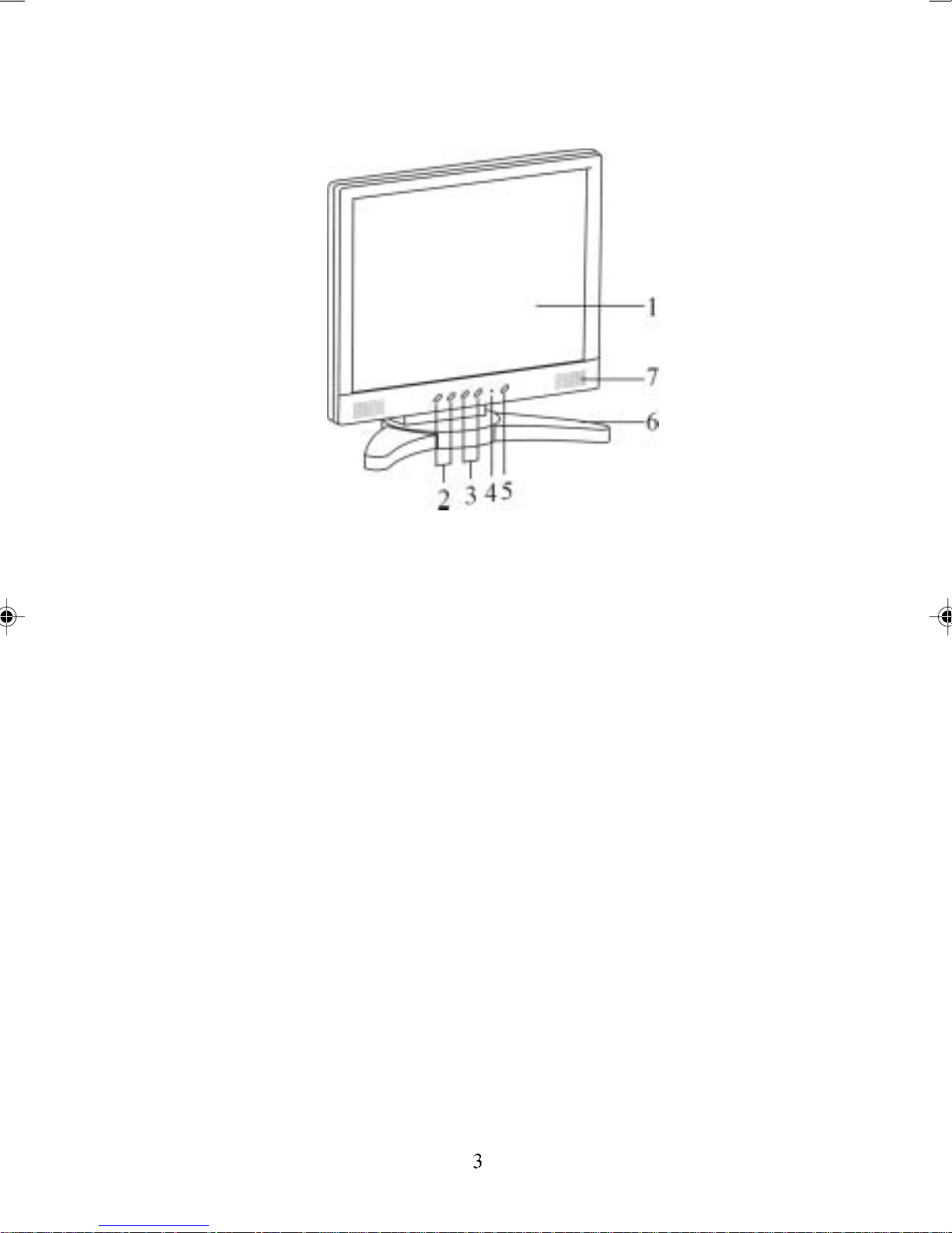
The LCD Monitor — Front View
Figure 1-1: The LCD Monitor Panel and Controls
1. LCD Screen
The LCD Monitor Screen is a 19” TFT 1280 x 1024 SXGA screen.
2. Function Control Buttons /OSD Menu Button
st
The 1
Menu and to select the function group. The 2
button allows you to display the OSD (On-Screen Display)
nd
button allows you
to select one of the control functions within each function group.
3. Adjustment Control Buttons
These two buttons allow you to adjust the selected control function
to accommodate your specific working environment. Press the
upper button (+) to increase the setting of the selected control
function and press the lower (-) button to decrease the setting of
the selected control function.
4. Power-On Indicator
This LED indicator lights up when the power is on. The LED
indicator will blink when the LCD Monitor is in power-saving mode.
Page 8
5. Power Button
Press this button to turn the Monitor on/off.
6. Monitor Stand
The Monitor Stand supports the LCD Panel. Loop the VGA signal
cable through the hole on the Monitor Stand.
7. Stereo Speakers
You can connect your PC’s Audio out port to the LCD Monitor’s
Audio in port and listen to your PC’s audio output with these
speakers.
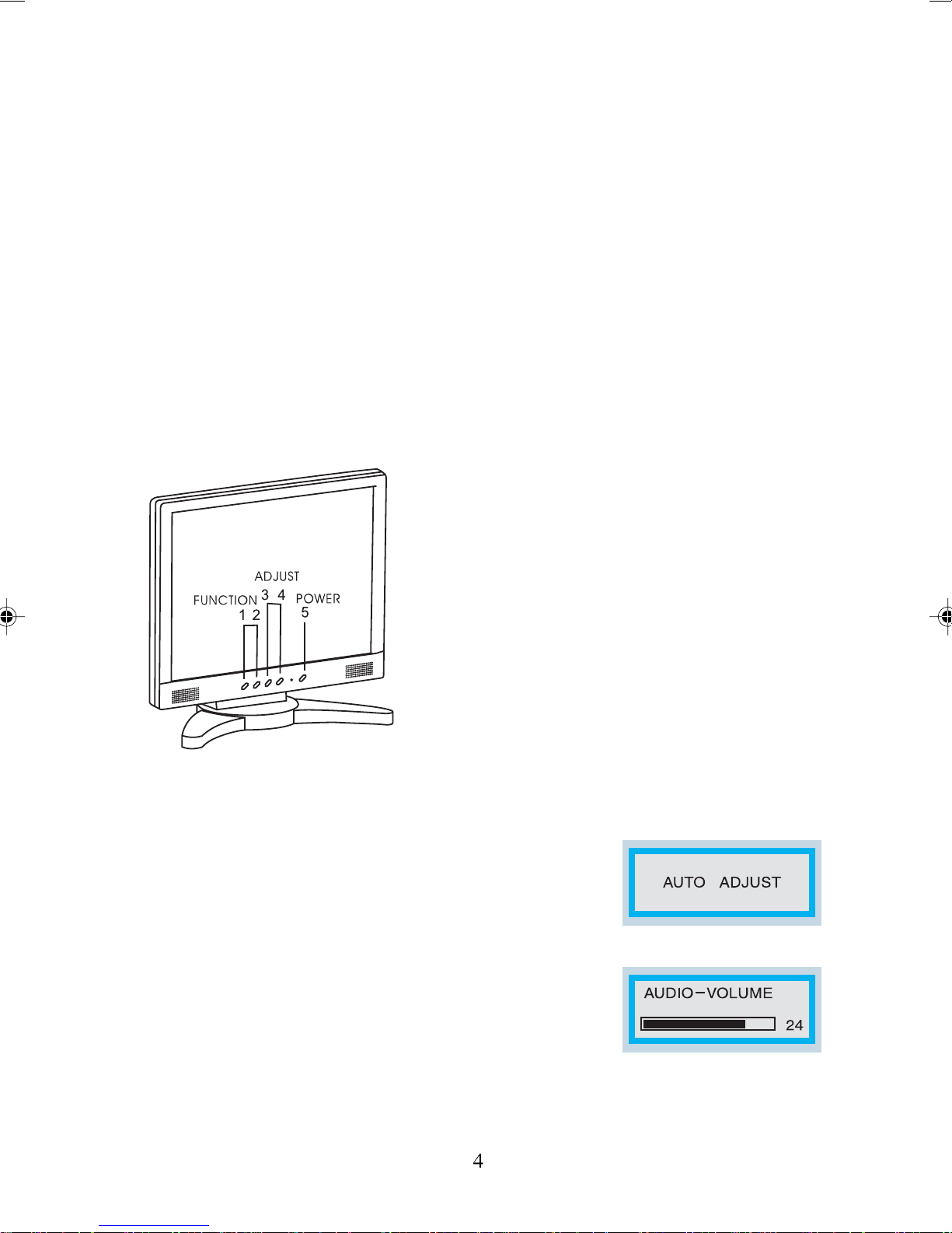
Hot Keys for Quick Adjustment of Monitor Settings
1.”Auto-adjust” hot key:
Press the 2nd function button to apply monitor
settings automatically. A small “AUTO ADJUST”
OSD is also displayed.
2.” Adjust-volume” hot key:
Press the 1st adjustment control button to adjust the
audio volume directly.
Figure 1-2: Hot Keys
Page 9

3.” Contrast-adjust” hot key:
Press the 2
the contrast of the display directly.
nd
adjustment control button to adjust
** To close the OSD windows, press the power button once.
The LCD Monitor — Rear View
Figure 1-3: LCD Monitor’s Rear Ports
1. DC Power Jack for AC adaptor
Connect the AC adapter cable to this jack.
2. Audio Line-in
Connect your PC’s line-out to this jack to listen the PC’s audio on
the LCD monitor’s stereo speakers. (You can also connect your
CD-ROM’s line-out to this jack.)
3. VGA Cable Connector
This 15-pin D-Sub VGA connector is used to connect to your PC’s
VGA card.
4. Digital VGA Cable Connect
This 24-pin DVI connector is used to connect to your PC’s Graphic
card if it is equipped a DVI connector.
Page 10

Adjustsing the Viewing Angle
Your LCD Monitor is designed to allow you to adjust it to a comfortable
viewing angle. The LCD Monitor’s vertical angle setting range is from -5°
to 20°. Please see
Figure 1-3
.
Figure 1-4: Angle Settings
• When positioning the equipment, make sure that the
main ports and sockets are easily accessible.
• Do not place your LCD Monitor close to a heat source.
• Do not place the LCD Monitor in direct sunlight or near a
window. Moisture and direct sunlight exposure can
seriously damage the LCD Monitor.
Page 11
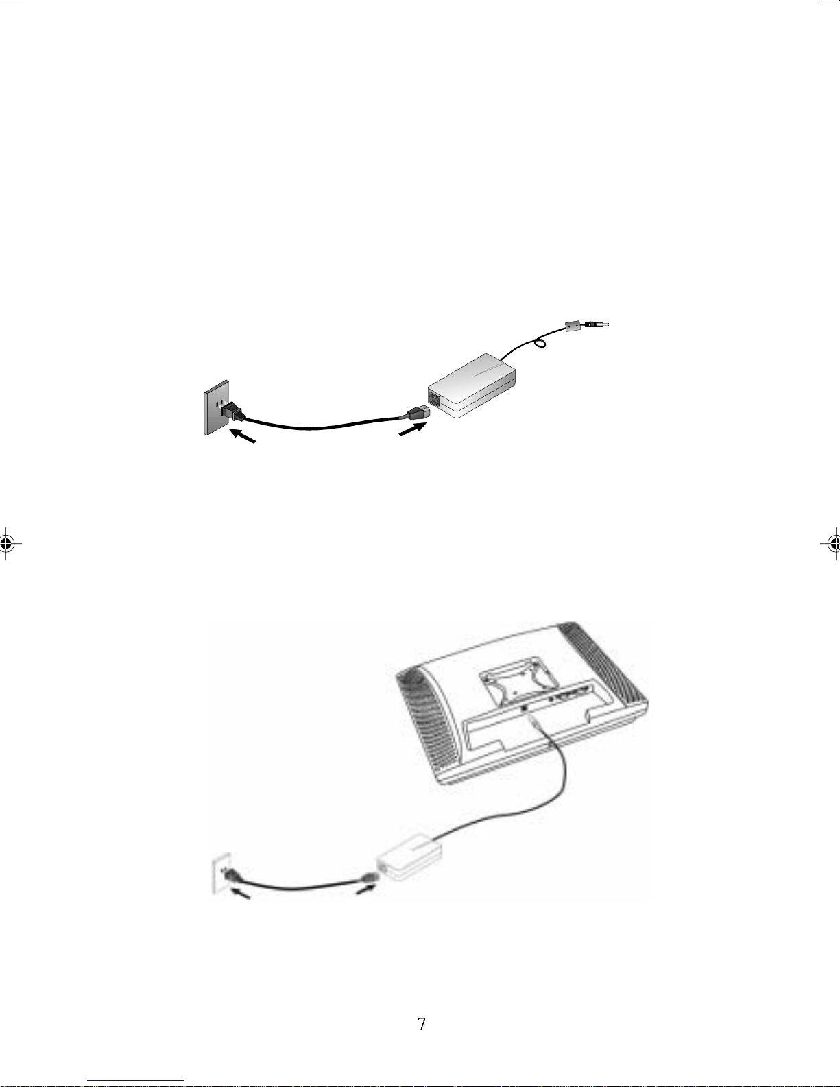
Connecting AC Power
Please refer to the following instructions for connecting the AC
power to the LCD Monitor.
1. Plug the female end of the power cable into the AC-adapter.
Plug the male end of the power cord into a wall socket. The
plug on the power cable will vary according to the electrical
standard in your area. Please refer to
Figure 1-5: The AC Adapter
Figure 1-4
.
2. Connect the power connector of the adapter into the jack of
the LCD Monitor. The DC power jack is located at the rear of
the Monitor near the USB Hub connector. Please refer to
Figure 1-5
.
Figure 1-6: Connecting Power to the LCD Monitor
Page 12
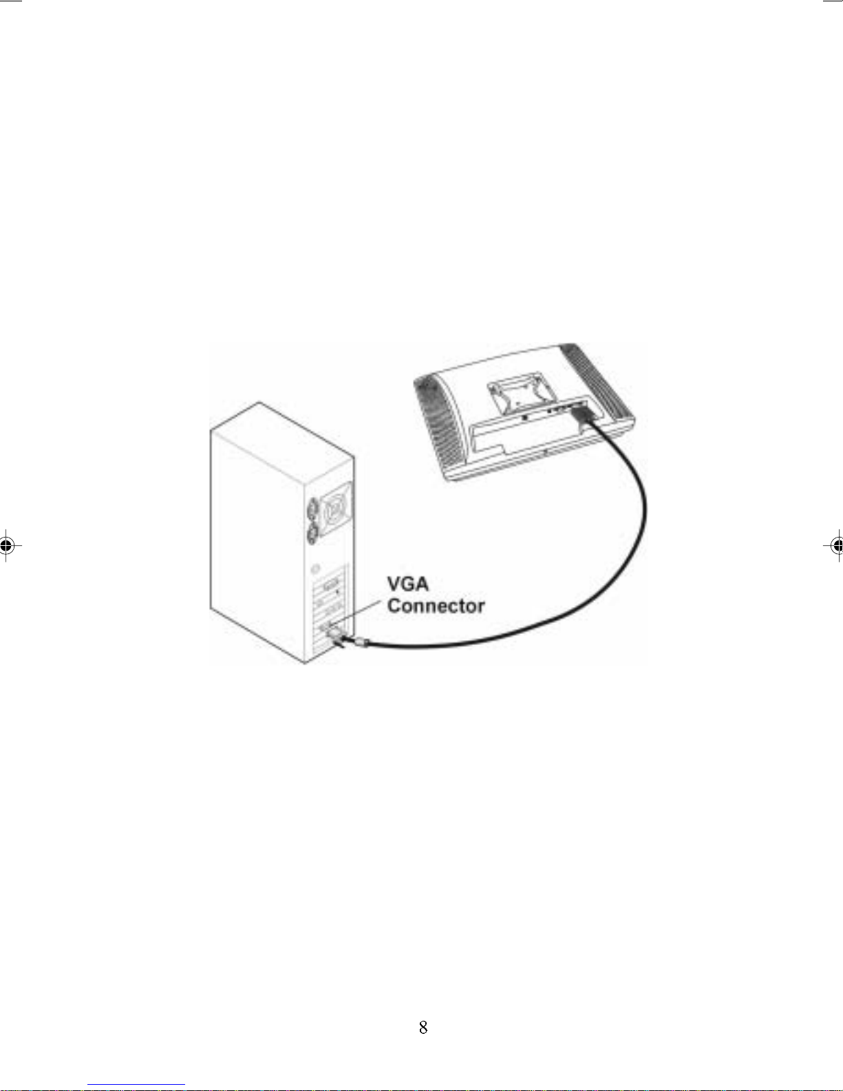
Connecting Video
1. Turn off your PC and the LCD Monitor before connecting your
LCD Monitor to the computer.
2. Connect one end of the VGA signal cable to the PC’s D-sub
VGA port and the other end to the monitor’s VGA port. Please
refer to
Figure 1-6.
3. If your PC has a graphic card with a 24-pin DVI connector, you
should connect it with the Digital 24-pin DVI signal cable.
Figure 1-7: Connecting the LCD Monitor to the PC
4. Make sure the signal cable heads are securely connected to
the VGA port (or DVI port) of your PC and Monitor. Tighten the
connecting screws to ensure a secure connection.
5. Turn on your computer and LCD Monitor.
Page 13

Connecting the Stereo Speakers
Please refer to the following instructions for connecting the LCD
Monitor’s stereo speakers.
1. Connect the sound cable to the Line Out of your PC’s audio card.
2. Connect the other end of the sound cable to the LCD Monitor’s line-in
jack. Please refer to
Figure 1-8: Connecting the Stereo Speakers
Figure 1-7
.
3. Y ou can adjust the sound volume of the stereo speakers by using
the speaker volume control function on the OSD (On-Screen
Display). Please refer to the next chapter for details.
Power Management System
The LCD Monitor complies with the VESA DPMS (version 1.0p) power
management proposal. The VESA DPMS proposal provides four
phases of power-saving modes by detecting the horizontal or vertical
sync signal.When the LCD Monitor is in power-saving mode or detects
an incorrect timing, the Monitor screen will go blank and the power
LED indicator will start to blink.
Page 14

The Display Controls
The LCD Monitor ’s Display Controls
This chapter covers the LCD Monitor’s On Screen Display (OSD).
Using the OSD, you can adjust the contrast, brightness, display
position, display clarity, and color temperature. You can also adjust
the stereo speaker volume and set OSD parameters. Please read
this chapter carefully to get the most out of your LCD Monitor.
Adjusting the Monitor ’s Display
The LCD Monitor features an intuitive, menu-driven, On-Screen
Display (OSD). You can access the OSD any time when the PC
is powered on. If the PC is in a power-saving mode, or is powered off, the OSD is inaccessible.
The OSD makes the adjusting of display settings quick and
simple. Take note of the following:
• Use the
through the various OSD items. The Function buttons can
also be used at any time to move through a palette of menu
items (such as suboptions within an OSD function).
• With a particular OSD function selected (such as Monitor
Control), use the
suboptions (e.g., H-Position or V-Position under Monitor
Control). The Adjustment buttons can also be used at any
time to change values for a particular setting, or to exit a
suboption.
Please refer to
options on your LCD Monitor
Function
Figure 1-1
buttons to access the OSD and scroll
Adjustment
for the location of the Function and Adjustment
.
buttons to access the
Page 15

OSD Main Menu
To access the OSD main menu, press the OSD Menu button (the first
Function button on your LCD Monitor). To scroll between the OSD
main menu options, use the second Function button on your LCD
Monitor. The highlighted option is the one that is currently selected.
Analog or digital mode is automatically detected by the Monitor.
A. Analog Mode
Each main menu and submenu item is covered below.
Pressing the OSD Menu button causes the following screen to
appear (an example):
Figure 2-1: The OSD Main Menu
The Monitor Control Option
The Monitor Control option allows you to adjust the
display characteristics of the LCD Monitor.
AUTO-ADJUST : Use this option to apply automatic
monitor settings.
H-POSITION: Use this option to move the LCD
monitor’s display left or right on a horizontal plane.
V- POSITION: Use this option to move the LCD
monitor’s display up or down on a vertical plane.
Page 16
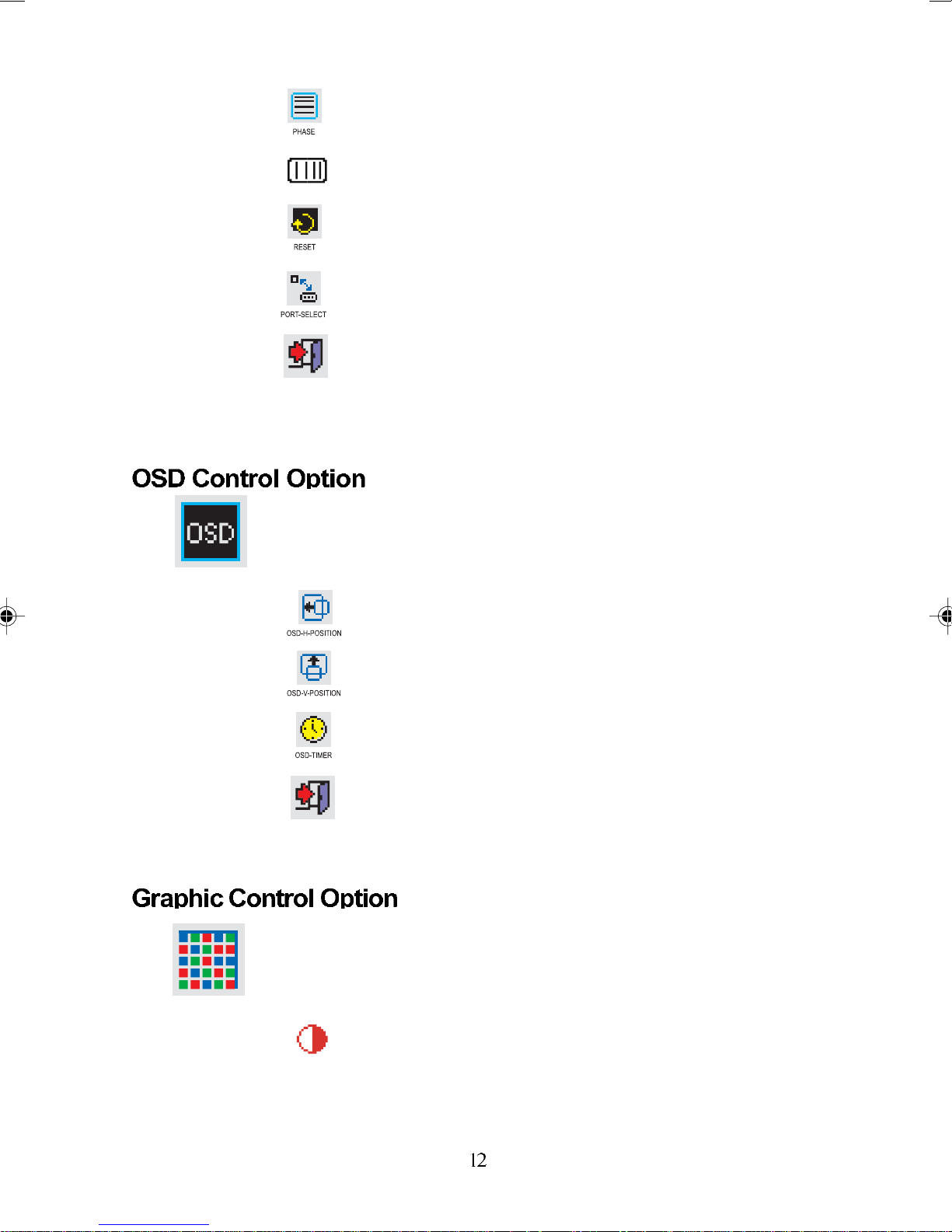
PHASE: Use this option to adjust the focus and
clarity of the display.
CLOCK: Use this option to adjust the display pixel
number alignment.
RESET: Use this option to reset the H- Position, VPosition, Phase and Clock parameters.
PORT-SELECT: Use this option to change input
between the VGA port and DVI digital port.
EXIT: Use this option to exit the Monitor Control
submenu.
The OSD Control option lets you adjust the position
of the OSD on the screen.
OSD-H-POSITION: Use this option to change the
position of the OSD on a horizontal plane.
OSD-V- POSITION: Use this option to change the
position of the OSD on a vertical plane.
OSD-TIMER : Use this option to change the OSD
display time.
EXIT: Use this option to exit the OSD Control
submenu.
The Graphic Control option lets you make adjustments that effect the contrast, brightness and color
of the LCD monitor’s display.
CONTRAST: Use this option to adjust the difference
between the lightest and darkest areas of the LCD
monitor’s display screen.
Page 17

BRIGHTNESS: Use this option to adjust the level of
light on the LCD monitor’s display screen. The
Brightness level should be adjusted in conjunction
with the Contrast item.
COLOR: Use this option to select the LCD monitor’s
color display. The available options are 9300, 6500
and User. The 9300 and 6500 options let you set the
Color Temperature to CIE coordinates 9300° or
6500° respectively. Selecting the user option lets
you make individual adjustments to the R, G and B
items.
R, G and B: Use this option to make individual
adjustments to the Red/Blue/Green (RGB) gain for
the color temperature.
Before adjusting these fields, select the User option
in the Color submenu first.
AUTO-LEVEL: Use this option to automatically
adjust the white balance display.
RESET: Use this option to reset Contrast, Brightness and Color parameters.
EXIT: Use this option to exit the Graphic Control
submenu.
The Misc Control option lets you select the OSD
display language, adjust the volume setting and view
system information.
LANGUAGE: Use this option to scroll to the desired
OSD display language. The supported languages
are German, English, French, Spanish, Italian, and
Japanese.
AUDIO-VOLUME: Use this option to increase or
decrease the volume of the LCD monitor’s sound
system.
INFORMATION: Use this option to view information
on the display mode and firmware version. This is a
display-only setting and cannot be adjusted further.
EXIT: Use this option to exit the Misc Control
submenu.
Page 18
OSD Exit Option
Use the OSD Exit item to close the OSD program.
The OSD Exit option lets you close the OSD
Program. Take note that the OSD will close by itself
if left inactive.
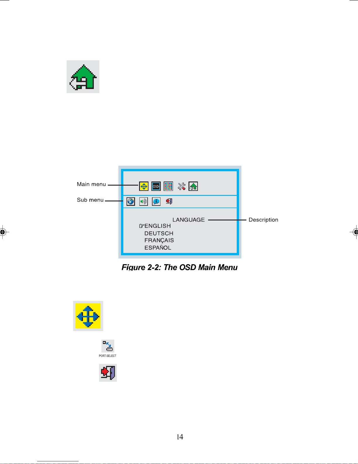
B. Digital Mode
Pressing the OSD Menu button causes the following screen to appear
(an example):
The Monitor Control Option
The Monitor Control option allows you to adjust the
LCD monitor’s display characteristics.
PORT-SELECT: Use this option to change input
between VGA port and DVI digital port.
EXIT: Use this option to exit the Monitor Control
submenu.
Page 19

OSD Control Option
The OSD Control menu option lets you adjust the
position of the OSD on the screen.
OSD-H-POSITION: Use this option to change the
position of the OSD on a horizontal plane.
OSD-V-POSITION: Use this option to change the
position of the OSD on a vertical plane.
OSD-TIMER : Use this option to change the OSD
display time.
EXIT: Use this option to exit the OSD Control
submenu.
Graphic Control Option
The Graphic Control option lets you make adjustments that effect the contrast, brightness and color
of the LCD monitor’s display.
Misc Control Option
CONTRAST: Use this option to adjust the difference
between the lightest and darkest areas of the LCD
monitor’s display screen.
BRIGHTNESS: Use this option to adjust the light
level on the LCD monitor’s display screen. It should
be adjusted in conjunction with the Contrast item.
RESET: Use this option to reset Contrast, Brightness and Color parameters.
EXIT: Use this option to exit the Graphic Control
submenu.
The Misc Control menu option lets you select the
OSD display language, adjust the volume setting
and view system information.
LANGUAGE: Use this option to scroll to the desired
OSD display language. The supported languages
are German, English, French, Spanish, Italian, and
Japanese.
Page 20

AUDIO-VOLUME: Use this option to increase or
decrease the volume of the LCD monitor’s sound
system.
INFORMATION: Use this option to view information
on the display mode and firmware version. This is a
display-only setting and cannot be adjusted further.
EXIT: Use this option to exit the Misc Control
submenu.
OSD Exit Option
Use the OSD Exit item to close the OSD program.
The OSD Exit option lets you close the OSD
Program. Take note that the OSD will close by itself
if left inactive.
Note:
1.NO VIDEO
When the monitor is ON and no Video signal is
being received, the “NO VIDEO” message will
be displayed.
2.Signal out of monitor’s supported range
When the frequency range is out of the
monitor’s specifications, or the incoming resolu
tion is higher than 1280x1024, the video data
will be turned off and a warning message
“OVER RANGE” will be displayed.
Page 21

Appendix A
LCD Monitor Specifications
LCD Panel 19” SXGA
Control
Functions
Power
On-Screen
Display (OSD)
Display Area
(mm)
Software Power switch with LED indicator
Main Menu Submenu
Monitor
Control
OSD
Control
Graphic
Control
Misc.
Control
OSD Exit
Auto Adjust / Horizontal Position /
Vertical Position / Phase / Clock /
Reset / Graph./Text / Port Select / Exit
OSD Horizontal Position / OSD Vertical
Position / OSD Timer / Exit
Contrast / Brightness / Color / R / G / B /
Auto Level / Reset / Exit
Language / Audio Volume / Information /
Exit
376.32x 301.056mm
(19 inch diagonal)
Display Colors 16.7M
Video Interface
Analog port: VGA Compatible Analog RGB (15-pin D-Sub)
Digital port: DDWG compliant Single Link Tmds Digital
Separate Sync. /Composite / Sync On Green
Visual Interface (DVI)
Page 22

Input Detection
AUTO-detection and OSD item for manual selection
Scanning
Frequency
H/V, Hz
(Analog mode)
Scanning
Frequency
H/V, Hz
(Digital mode)
Power
Management
Power
Consumption
(ON/OFF, W)
Dimensions
WxHxD mm
Net Weight (Kg)
(Approx.)
24-80k
50-75
30-80k
50-75
Meets VESA DPMS
ON :46W max. OFF:5W max.
(Measured from AC inlet)
430 x 431 x 240
7.0±1
Power Supply
Environment
Audio (Two 1 Watt
speakers with
amplifier)
Regulatory
12V/4.16A, 50W
Universal Input AC Adapter (External)
Operating Temperature: 0 to 40° C
Relative Humidity: 10% to 85%
Yes
CUL, TÜV-GS, CE, VCCI, FCC B DoC,
TÜV-Ergonomics, TCO ’99, BSMI
Page 23
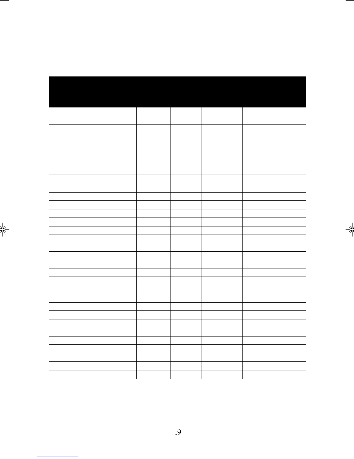
Supported Timing
Appendix B
Item Standards Resolution
1 NEC 640x400 25.20 70.15 31.50 -/- A/D/G
PC98
2 NEC 640x400 21.05 56.42 24.83 -/ - A/G
PC98
3 MAC 13” 640x480 30.24 66.67 35.00 -/- A/D/G
mode
4 MAC 16” 832x624 57.28 74.55 49.73 -/ - A/D/G
mode
5 MAC 17” 1024x768 80.00 75.02 60.24 -/- A/D/G
mode
6 V GA 640x350 25.18 70.09 31.47 +/- A/D/G
7 V GA 640x400 25.18 70.09 31.47 -/+ A/G
8 V GA 640x480 25.18 59.94 31.47 -/- A/D/G
9 VESA 640x480 31.50 72.81 37.86 -/- A/D/G
10 VESA 640x480 31.50 75.00 37.50 -/- A/D/G
11 VESA 800x600 36.00 56.25 35.16 +/+ A/D/G
12 SVGA 800x600 40.00 60.32 37.88 +/+ A/D/G
13 VESA 800x600 50.00 72.19 48.08 +/+ A/D/G
14 VESA 800x600 49.50 75.00 46.88 +/+ A/D/G
15 VGA 720x400 28.32 70.09 31.47 -/+ A/G
16 XGA 1024x768 65.00 60.00 48.36 -/- A/D/G
17 VESA 1024x768 75.00 70.07 56.48 -/- A/D/G
18 VESA 1024x768 78.75 75.03 60.02 +/+ A/D/G
19 1024x768 71.64 66.13 53.96 +/+ A/D/G
20 VESA 1152x864 108.00 75.00 67.50 +/+ A/D/G
21 1152x870 100 75.06 68.68 -/- A/D/G
22 VESA 1280x960 108.0 60.0 60.0 +/+ A/D/G
23 VESA 1280x1024 108.0 60.02 63.98 +/+ A/D/G
24 VESA 1280x1024 127.0 69.85 74.88 +/+ A/D/G
25 VESA 1280x1024 135.0 75.03 79.98 +/+ A/D/G
26 SUN 1024x768 64.13 59.98 48.29 H+V A
27 SUN 1024x768 74.25 70.04 56.59 H+V A
Dot Clock
(MHz)
Vertical
Scanning
Frequency
(Hz)
Horizontal
Scanning
Frequency
(kHz)
Sync
Polarity or
composite
sync (H/V)
Operating
Mode
*A=Analog Mode ; D=Digital Mode ; G=Sync On Green Mode
*Once a mode is optimized, there is no need to make any further
adjustment as long as the VGA card remains unchanged.
*Specifications are subject to change without notice.
Page 24

Appendix C
Troubleshooting Procedures
This LCD Monitor was pre-adjusted in the factory with standard VGA
timing. Due to output timing differences among various VGA cards, you
may initially experience an unstable or unclear display when a new
display mode or new VGA card is selected.
This LCD Monitor Supports Multiple VGA Modes. Refer to Addendum for a listing of the factory preset modes supported by this LCD
Monitor.
PROBLEM: Display is Unclear and Unstable
To stabilize and clarify your display, follow this procedure in this order:
1. It’s best to adjust the display on a screen displaying of vertical
lines. In Windows, load a wallpaper bitmap that has vertical
lines in it (or you can select the window shut down screen).
2. After loading the wallpaper, open the OSD and select the
“Clock” function. Press the top (or bottom) Adjustment Control
button and continue pressing the button until you see vertical
dark and light lines across the screen.
3. When you can see distinct light and dark vertical bands, stop
pressing the Adjustment Control button. Now press the oppo
site (top or bottom) Adjustment Control button. The vertical
dark and light bands will decrease in number. Keep pressing
the button until the distinct bands disappear and you have a
clear display.
4. Next, press the Function Control button to choose the “Phase”
function. The Phase will adjust the horizontal display. Press
the top (or bottom) Adjustment Control button and you will see
horizontal dark and light lines appear. The number of lines
increases as you press the button. Now press the bottom (or
top) Adjustment Control button until the lines disappear and
you have a clear display.
Page 25

PROBLEM: There is no LCD Display
If there is no display on the LCD, please perform the following steps:
1. Make sure that the power indicator on the LCD Monitor is lit,
all connections are secure, and the system is running on the
correct timing. Refer to the Addendum for information on
timing.
2. Turn off the LCD Monitor and then turn it back on again.
Press the upper Function Control button (refer to Chapter 2)
once and then press either the upper or lower Adjustment
Control button several times. If there is still no display, press
the other Adjustment Control button several times.
3. If step 2 does not work, connect your PC system to another
external CRT. If your PC System functions properly with a
CRT Monitor but it does not function with the LCD Monitor,
and the LCD Monitor’s power LED is blinking, the output
timing of the PC’s VGA card may be out of the LCD’s
synchronous range. Please change to an alternate mode
listed in Addendum or replace the VGA card and repeat steps
1 and 2.
4. If the PC does not function with the CRT monitor as well,
check the BIOS to see if there is a dual scan setting under the
display mode item. Set the BIOS display mode to
or
CRT
and try again. If there is still no display, then there
Dual Scan
may be a problem with your system. Contact technical
support.
5. If the power LED is not lit, check to see if the AC power
connector is securely connected. Verify that the AC adapter
LED is lit. If the AC adapter LED is not lit, please contact your
dealer for assistance.
 Loading...