

Page 1

ArtixScan 6000XY Installation and Operation Manual 1
1 Introduction
Congratulations on your purchase of the Ar tixScan 6000XY scanner. The 42-bit highresolution ArtixScan 6000XY is specifically for graphic arts and imaging pr ofessionals.
This manual will help you in the installation and operation of your scanner .
Specifications
Type Desktop, XY technology scanner
Image Sensor Tri-linear 8,000 element CCD
Mechanical Resolution 6,000 dpi
Optical Resolution 2,000 dpi
Sample Depth 14 bits per color
Dynamic Range 3.7D
Scanning Area Reflectiv e: 12” x 17” (305 mm x 432 mm)
Transparency: 12” x 17” (305 mm x 432 mm)
Scanning Productivity 15 scans per hour (6 cm x 7 cm, 250%, 300dpi, CMYK)
Interf a c e SCSI-2
Lamp Source Cold Cathode Lamp
Temperature Operating: 61 - 80°F (16 - 27°C)
Stor age: -10 - 55°F
Humidity 10% - 85%
Dimensions 14” x 34” x 27.5” (36 mm x 87 mm x 70 m
Net W eight 147 lb (67 kg)
Pow er Consumption Operation: 290 W
Standby: 200W
C e r tifications CSA, T U V, FCC class B, CF
Page 2

2 ArtixScan 6000XY Installation and Operation Manual
2 Site Power and Working Space
This section describes the working conditions and working space for operating the
ArtixScan 6000XY .
General Requirements
Before unpacking your scanner, make sure that the site where the scanner will be
installed is big enough to allow for easier operation.
• Make sure that the operating environment for the scanner is fr ee of dust and other
contaminants.
• Allow adequate ventilation space (no less than 10 inches) around the scanner.
• Place the scanner on a flat, stable surface that is not subject to vibration.
• Make sure that the scanning surface will not be exposed to dir ect sunlight or other
sources of bright light.
• A void placing the scanner close to sources of extreme temperature.
• A void connecting the scanner to a power source that might experience power
surges.
• A void positioning the scanner in the path of heavy traf fic wher e it may get bumped.
Once the scanner has been placed in a suitable location and is ready to be connected
to the host computer , it is time to pr oceed to installing the necessary har dwar e and
software components for the scanner.
SCSI cables
Your scanner should be placed within 3 feet of the computer. Use the SCSI cable that
came with your scanner .
Minimum Macintosh requirements
• Apple Power Mac with PCI bus (150 MHz)
• Apple Macintosh system software version 8.5 or higher
• CD-ROM drive
• 64MB of available RAM
• 1 GB hard disk space
• Color monitor at least 17” with 24-bit color display ability
Safety Instructions
To prevent the electric shock, the cover should only be removed by a qualified service
engineer.
Page 3
ArtixScan 6000XY Installation and Operation Manual 3
This warning icon appears inside the scanner which indicates that the scanner lamps
are hot, you should wait for several minutes for them to cool off.
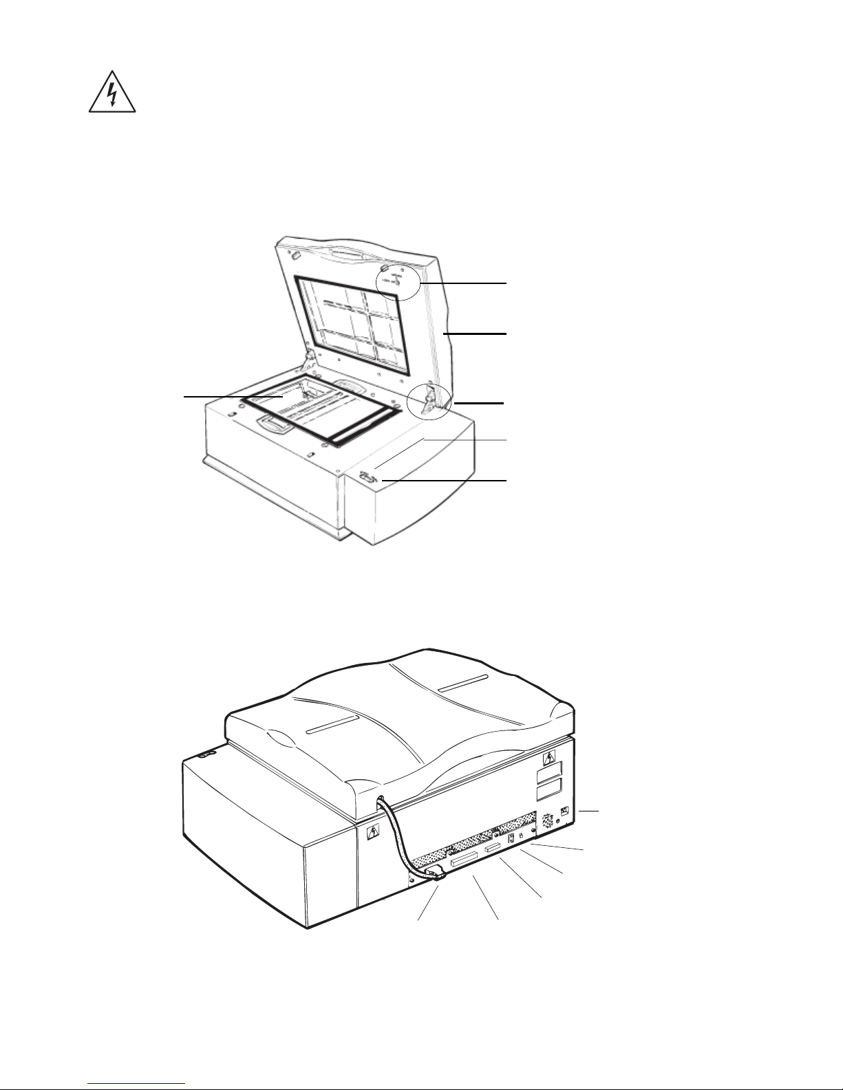
Scanner front and back view
A. Front view of the scanner
B. Back view of the scanner
6
TMA Connector
50-pin SCSI Port
25-pin SCSI Port
SCSI ID Switch
Ter minator Switch
D C P ow er Input P ort
TMA Carriage Lock
Scanner Carriage Loc k
Top Cover (TMA)
Status LED Indicator
Light Button
Scan Bed
Page 4
4 ArtixScan 6000XY Installation and Operation Manual
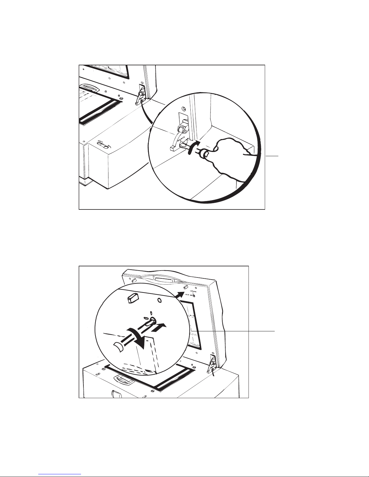
Unlocking scanner carriage
Unlocking TMA carriage
UNLOCK
LOCK
Tur n the scre w
countercloc kwise to
unlock the scanner
carr iage.
Tur n the scre w
countercloc kwise to unloc k
the TMA carriage .
Page 5
ArtixScan 6000XY Installation and Operation Manual 5
3 Powering Up
This section describes the power up sequence for the ArtixScan 6000XY.
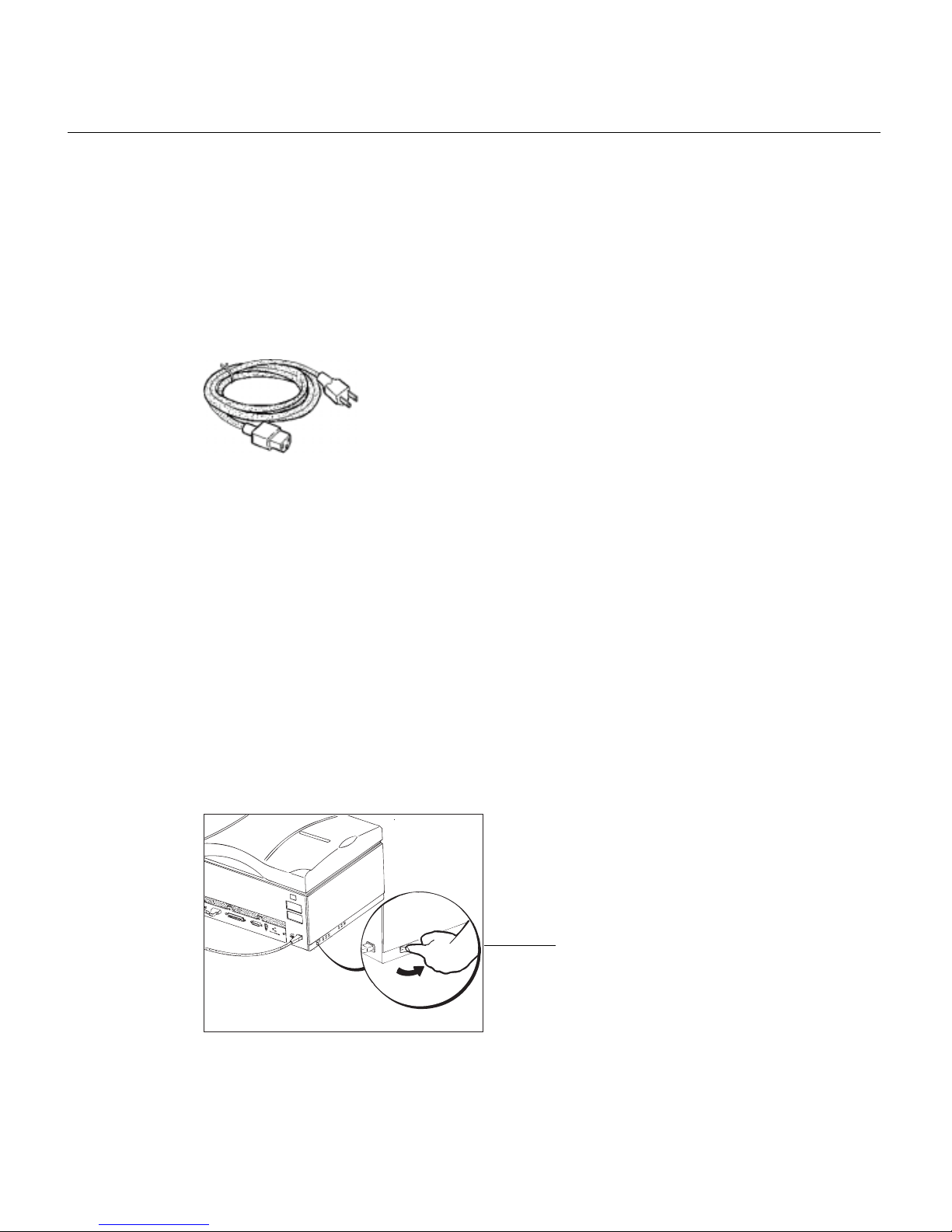
Power cable
The power cable shown below is a North American type that complies with United
States and Canadian requirements. Power cables used in other ar eas may have a
different look.
Voltage
The ArtixScan 6000XY scanner is preset to the voltage in your country. There is no
need to manually select the voltage; however, make sure that the label next to the
power entry module indicates the correct voltage. Contact your dealer if the label
indicates an incorrect voltage.
Power cord connection
Caution! Make sure your scanner carriage is unlocked prior to connecting it to a
power source.
1. The scanner should be switched to the “OFF” position.
2. At the scanner back panel, connect the power cord.
3. Connect the other end of the power cord to a grounded power sour ce.
Switch the scanner’s pow er to
the “Off ” position.
Page 6
6 ArtixScan 6000XY Installation and Operation Manual
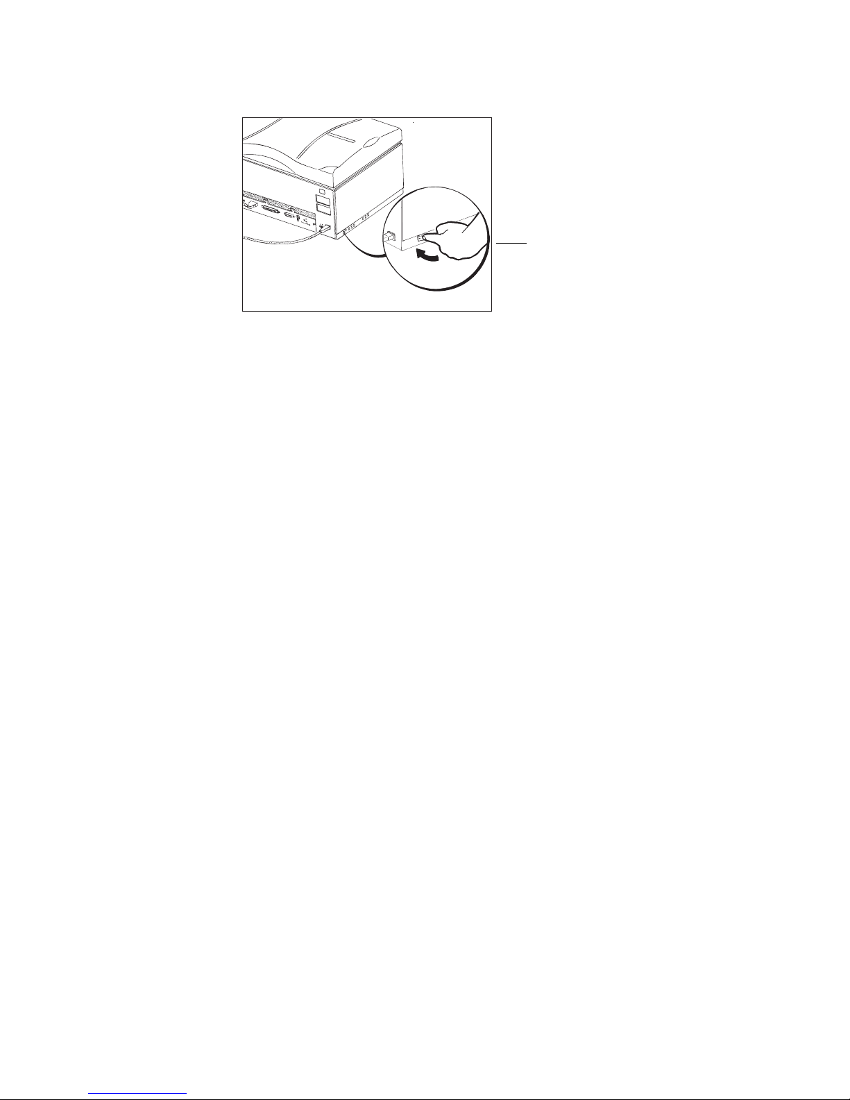
4. Switch the scanner’s power to the “On” position.
Power up self-test
The following sequence of events should take place after powering up the scanner:
• The scanner performs a self-test by homing the carriages and camera box. Through
the platen glass, you can observe the carriage moving, and you will hear a series of
clicking noises associated with the operation of the scanner motors. These “clicking” noises are normal. However, if you hear loud grinding noises or any other
abnormal sound, turn the scanner off immediately and contact your dealer.
• The Status lamp turns red for a few seconds when the scanner power is turned on.
• The Status lamp goes off when the scanner checks the power supply.
• The Status lamp turns green for about 30 seconds while the scanner performs selftest. If this step is completed successfully, the lamp remains on green.
If an error occurs and the scanner is not able to start pr operly, the status indicators
will display a steady red light. If this happens, turn off the scanner and contact your
dealer.
Switch the scanner’s
po w er to the “On”
position.
Page 7
ArtixScan 6000XY Installation and Operation Manual 7
4 Connecting your scanner
This section provides information on installing the ArtixScan 6000XY on the
Macintosh. The procedures ar e divided into two main sections: 1) Installation for
Macintosh computers that feature built-in SCSI ports; and 2) Installation for the new
Macintosh G3/G4 computers with built-in USB ports. For the new G3/G4 computers,
you will be installing the SCSI interface card included in the scanner package.
Important: Before connecting, make sure that the computer, your scanner, and all other
devices are turned off.
Installation for Macintosh computers with built-in
SCSI ports
A. Connecting the scanner
1. Shut down your computer .
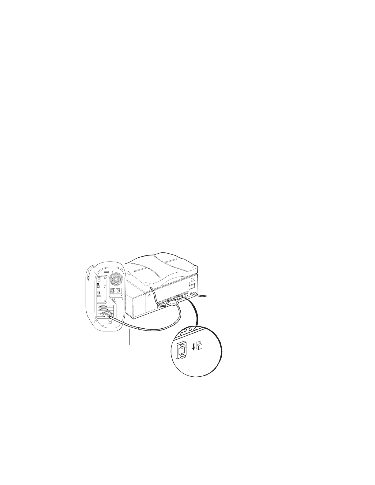
2. Connect the scanner to your computer , using the SCSI cable provided in the
scanner package.
Note: See the next section for details on termination
(1)
SCSI
ID
TERMINATION
OFF
ON
6
3. Plug the power cord to the power connector at the back panel of the scanner, and
plug the other end of the power cord to your AC power source or wall outlet.
4. Turn on your scanner and wait for all the lights on the front panel to stop blinking
and stay on steady.
5. Power up your Macintosh.
Connect the SCSI
c a b le to the
Macintosh SCSI
por t.
Page 8
8 ArtixScan 6000XY Installation and Operation Manual
B. Termination
1. If the scanner is the last device on the SCSI chain, set the internal terminator switch
on the back of the scanner to the “ON” position. There is no need to install an
external terminator on any of the other SCSI devices on the chain.
(1)
SCSI
ID
TERMINATION
OFF
ON
6
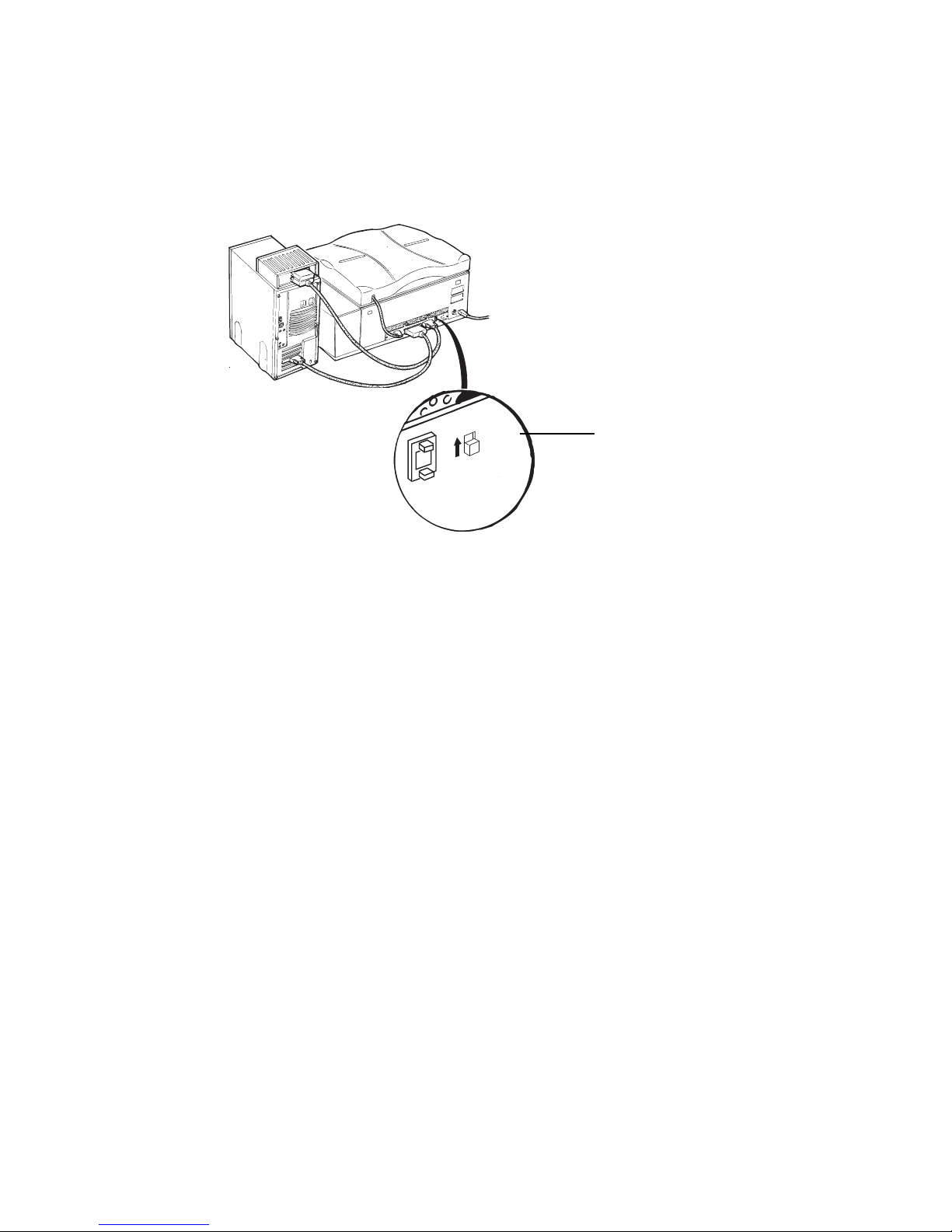
2. If the scanner is not the last device on the SCSI chain:
• Make sure the internal terminator switch located at the back of the scanner is set
to the “OFF” position.
• Make sure the last device on the SCSI chain is terminated.
Installation for the new G3/G4 Macintosh computers
(without built-in SCSI ports)
A. Installing the interface card
Before installing the interface card, make sur e you turn off your computer and
peripherals. Then follow the steps below:
If the scanner is the last
de vice , set the ter minator
switch to the “On” position.
Page 9
ArtixScan 6000XY Installation and Operation Manual 9
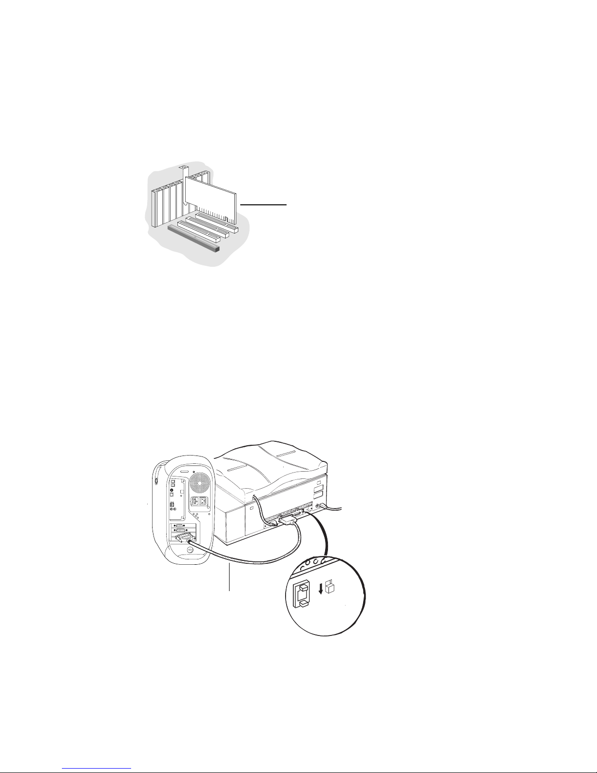
1. Shut down your computer and unplug the power cord. Next, open your computer .
2. Look for an available PCI card slot (typically white or ivory) in your computer .
Remove the slot cover , and insert the PCI SCSI card into the slot. Push the card in
to make sure it is seated all the way in the slot. This is important, as an improper
card connection will make you unable to use your scanner, and you will then have
to remove the computer case and reinsert the car d.
3. Close the computer.
B. Connecting the scanner
1. Shut down your computer .
2. Connect the scanner to your computer , using the SCSI cable provided in the
scanner package.
Note: See the next section for details on termination.
(1)
SCSI
ID
TERMINATION
OFF
ON
6
3. Plug the power cord to the power connector at the back panel of the scanner, and
plug the other end of the power cord to your AC power source or wall outlet.
4. Turn on your scanner and wait for the lights on the front panel to stop blinking and
SCSI Card
Inser t the SCSI card to the PCI
SCSI card into the slot.
Connect the SCSI cable
to the Macintosh.
Page 10

10 ArtixScan 6000XY Installation and Operation Manual
stay on steady.
5. Power up your Macintosh.
C. Termination
If you are connecting the scanner in a daisy chain to other SCSI devices (such as a
CD-ROM drive), take note of the following:
A.If the scanner is the last device on the SCSI chain, set the internal terminator
switch on the back of the scanner to the “ON” position. There is no need to
install an external terminator on any of the other SCSI devices on the chain.
(1)
SCSI
ID
TERMINATION
OFF
ON
6
B. If the scanner is not the last device on the SCSI chain:
• Make sure the internal terminator switch located at the back of the scanner is set
to the “OFF” position.
• Make sure the last device on the SCSI chain is terminated.
C.Installing the software
Install all the software on your ScanW izard Pr o CD-ROM, which contains the
ScanWizard Pr o scanning software, ICC profiles and the Microtek Scanner
Profiler™ software for calibrating the Ar tixScan 6000XY.
To do this, insert the ScanWizard Pro CD-ROM into your CD-ROM drive. When the
CD-ROM icon appears on your Macintosh desktop, open the software folders
individually, then double-click the Installer icon on each folder to install the
respective programs one at a time.
If the scanner is the last de vice ,
set the ter minator switch to the
“On” position.
Page 11

ArtixScan 6000XY Installation and Operation Manual 11
5 Operating your scanner
This section discusses three sections:
• Scanner Panel
• Power up sequence
• Placing originals in your scanner
Scanner Panel
The Scanner Panel, located at the upper right corner, is used for power up. The panel
has a push button (with LED indicator) and one LED indicator.
LED indicator information:
Power Push Button
This push button shows power status.
On (Green light) Power is on.
Off Power is off.
When the push button is pressed, the scanner carriage starts to travel to the scanning
lamp replacement position.
LED Indicator
This LED indicates the status of the scanner.
Green Scanner is ready for operation.
Blinking Green Scanner is busy or during self-test
Red Scanner malfunction
Off Indicates the TMA is not closed, or the
scanner carriage for the reflective
materials is not in position.
Page 12

12 ArtixScan 6000XY Installation and Operation Manual
Power up sequence
Follow the power up sequence below:
1. Turn on your Macintosh.
2. Turn on your scanner by pressing the Power Push button on the right corner. You
will observe the following:
1) On the scanner panel, the lamp turns green while the Status lamp turns red
for a few seconds.
2) The Status lamp blinks green, indicating system self-test is starting.
3) The Status lamp becomes a steady green, indicating that the scanner is
ready for operation.
If the lamp indicator remains red or blinking gr een, this indicates the scanner is
faulty or not ready.
To fix this, turn the scanner off and turn it back on. If the LED is still red, contact
Microtek Service.
Shutdown is performed by exiting the application and then turning off the main
power switch.
Placing originals
Depending on the material you are scanning, you will be doing one of the following
below:
• Placing originals on the scan bed
• Using customized masks
• Using 35mm slide holder
Placing originals on the scan bed
For single originals:
Tape the original to the scan bed. Align the top right corner of the original with the
0,0 corner of the glass (which is at the lower right corner).
When scanning a thick reflective original such as a book, you may scan with the Top
Cover open.
Page 13

ArtixScan 6000XY Installation and Operation Manual 13
For multiple originals:
When prescanning a “batch” images, tape all to the scan bed, and then scan in a
single pass. The originals must be of the same type (transparency or reflective), but
can be different in size or media (transparency or negative).
• Tape the first original at the 0,0 corner of the glass.
• Tape the originals toward the lower left corner of the scan bed, making sur e the
originals do not overlap. If necessary, continue to the next row. It is best to place the
originals in order, and not spread them randomly all over the glass bed.
Using customized masks
When you use the masks (included with your scanner), place the originals. These
masks are used for scanning transparencies, negatives, and r eflectives.
W orking with the scanner is convenient and productive with the mask. Advantages
are:
• Preparing the originals in advance at another place while the scanner is busy with
other scans.
• With the mask grid lines, positioning the originals is easier.
• The scan bed can be kept clean, as there are no tape marks.
• Defining multiple scan job customized formats. The defined formats will appear in
the scan job window. After preview, each scanned image is displayed as a separate
preview.
Preparing the customized mask
The customized mask is an A3 (11" x 17") opaque sheet; one side of the mask is for
transparencies, the other for reflectives (see the label on the mask). A set of barcode
windows appears at one edge; the first and the last barcode windows ar e always open.
For Transparency:
• Mark the outlines of the original on the transparency side of the mask, according to
the format you want to customize. The first original outline should be near the
(1,0) point at the lower right corner of the mask.
P osition (1,0)
Page 14

14 ArtixScan 6000XY Installation and Operation Manual
• Use a sharp knife to cut out a window for each original. Make sure not to cut the
mask barcodes.
• With the same method, you can make a mask for differ ent sizes.
• Mount the holder in the scanner with the printed side facing you; insert the 2 right
registration holes of the holder into the registration pins on the scan bed. The right
side of the holder should be aligned with the right side of the glass.
• For more than 20 slides, use the second slide holder.
• Mount the second slide holder on the scanner next to the first holder . Make sur e
the jigsaw edges of the 2 holders interlock. See the figure below.
Mask barcodes
area
The two guide-holes.
Mak e a mask f or
diff erent siz es .
Page 15

ArtixScan 6000XY Installation and Operation Manual 15
• Place the mask on the scan bed.
The figure below shows the customized mask with cut windows for 5 transparencies.
Do not cover bar-code
37 2
1
0
367548910111213141617 1518192021222324252627282930313233343536383940414243
2
1
0
3
67548
9
10111213141617151820212224252627282930
19
23
Cat. No.
509D1L005
4
23
2
1
0
3
67548
9
10111213141617151820212224252627282930
19
37
2
10
3675489
10111213141617 1518192021222324252627282930313233343536383940414243
USER DEFINED MASK
User mask name
TRANSPARENCY SIDE
T
a
p
e
t
r
a
n
s
p
a
r
e
n
c
y
e
m
u
l
s
i
o
n
s
i
d
e
d
o
w
n
1
345
6
2
7
• Mount the mask without originals in the scanner with the transparency side facing
up; insert the mask’s registration holes into the registration pins of the scan bed.
Place the mask.
Customized mask
with cut windo ws f or 5
tr ansparencies.
Page 16

16 ArtixScan 6000XY Installation and Operation Manual
Note: The 0,0 corner of the mask is approximately above the 0,0 corner of the scan bed.
For the reflective material:
• T ape the reflectives to the reflective side of the mask, according to your customized
format. T aping the originals is similar to dir ectly place your original on the scan
bed. Make sure not to cover the bar code windows.
• To mount in the scanner, turn the mask over so that the transpar ency label of the
mask faces up. Align and insert the mask registration holes into the r egistration
pins of the glass.
Transparency side
Using the customized mask
(Note: This section should work with the software, so presently it is left blank.)
Using the slide holder
The slide holder can hold up to 20 pieces of 35mm slides. W e recommend you insert
your slides row by row, that means, when the first row is full, continue to the next
row.
Transparency side
Align and inser t the mask
registr ation holes .
Inser t the slides ro w b y ro w .
Page 17

ArtixScan 6000XY Installation and Operation Manual 17
Appendix A: Service and Maintenance
This appendix discusses regular maintenance which covers scanning lamp replacement and glass plate cleaning.
Lamp Replacement
Your ArtixScan 6000XY scanner consists of 3 scanning lamps:
• One scanning lamp in the transparency scanning carriage (inside the scanner’ s top
cover)
• Two scanning lamps in the reflective scanning carriage
In the following situations you should replace the scanning lamps:
• The light level is low. This rule applies to both the transparency and reflective
scanning lamps.
• The scanning lamp does not light up.
Replacing the Transparency Scanning Lamp
1. Power off your scanner .
Note: The scanning lamp is hot. Wait a few minutes for cooling off scanning lamp.
2. Lift the top cover up.
Note: In operation, we recommend you place cardboard on the scan bed to prevent
damaging the glass.
3. Unscrew the 4 screws which holds the 4 corners of the top cover. When unscrewed,
the screws sprint out a little, there is no need to r emove the screws.
Lift the top co ver
up.
Page 18

18 ArtixScan 6000XY Installation and Operation Manual
4. Gently close the top cover .
Note: Make sure the cover is closed properly. If not, it may suddenly spring open.
5. Remove the top cover by holding the two diagonal corners, then lift it.
When the top cover is removed, the scanning lamp can be visually inspected.
Tur n the scre w countercloc kwise
to unscrew .
Lift the top co ver.
Inspect the scanning
lamp.
Page 19

ArtixScan 6000XY Installation and Operation Manual 19
6. To remove the scanning lamp, first gently pull one end of the lamp inward.
7. Then lift the other end up.
8. To insert the new scanning lamp, follow these guides:
• Make sure when inserted, the lamp with the lamp window facing down.
• Place the top cover back in its original position.
• Open the top cover.
• Screw the 4 screws in each 4 corners of the lamp assembly.
• Power up the scanner, in a while, visually inspect the new lamp illuminates.
Replacing the Reflective Scanning Lamp
1. Power up your scanner. The Status indicator lights gr een.
2. Lift the top cover up.
3. On the front panel, holding down and press the Light button for about 20 seconds,
then release the button. The scanner carriage with the scanning lamps will position
to the center of the scan bed.
S
T
A
T
U
S
L
I
G
H
T
Pull the scanning
lamp out.
Holding down the Light
b utton f o r 20 seconds.
Page 20

20 ArtixScan 6000XY Installation and Operation Manual
4. Power off your scanner .
Note: The scanning lamp is hot. Wait a few minutes for cooling off scanning lamp.
• Unscrew the 4 screws that fasten the scan bed glass to the scanner. To unscrew,
rotate the screws 90° counter clockwise.
Closed
Open
• Lift the 2 handles of the glass plate.
• Pull out the glass plate.
• Place the glass plate on a soft surface.
Lift the tw o handles .
Place the glass plate .
Page 21

ArtixScan 6000XY Installation and Operation Manual 21
• To remove the lamp, first push the lamp to the back of the scanner .
• Then pull the lamp out.
• Insert a new lamp. Make sure the lamp window faces upwards and inwards.
Note: Always replace both scanning lamps, even if only one is faulty.
7. Using the handles to lift the glass, then place it back in its original scan bed.
8. Thread the 4 screws that secur e the glass to the scanner. To tighten the screws,
rotate the screws 90° clockwise.
Top view of screw caps is shown below.
Open
Closed
9. To verify if the new scanning lamps work, scan a photograph in the reflective mode.
Push the lamp to the
bac k of the scanner .
Page 22

22 ArtixScan 6000XY Installation and Operation Manual
Preparing to clean the glass plates
The scan bed and top cover glasses require regular cleaning.
1. Use mild glass cleaning solution -- such as Windex -- to clean glass surfaces, as it
leaves no dirts after drying. The clean solution should not contain wax or ammonia.
Note: To prevent the cleaning solution leak under the glass surfaces, do not pour
cleaning solution directly on the glass.
2. Wipe gently with soft cloth, chamois leather, or rice paper for it does not leave
residue of fibers.
3. When the glass is clean, use an air spray or a soft brush to puff dust and dry the glass.
Note: Use an anti-static cleaner to eliminate static charge.
Cleaning the top cover glass
1. Power off the scanner .
Note: The scanning lamp is hot. Wait a few minutes for cooling off scanning lamp.
2. Lift the top cover up.
Wipe gently with soft cloth.
Lift the top co ver up .
Page 23

ArtixScan 6000XY Installation and Operation Manual 23
Note: In operation, we recommend you place cardboard on the scan bed to prevent
damaging the glass.
3. Unscrew the 4 screws which holds the 4 corners of the top cover. When unscrewed,
the screws sprint out a little, there is no need to r emove the screws.
4. Gently close the top cover .
Note: Make sure the cover is closed properly. If not, it may suddenly spring open.
5. Grip the diagonal corners of the top cover , then lift it.
6. Clean the glass plate surface.
7. Reposition the top cover to its original place, then tighten the 4 screws at the upper
and lower corners.
Tur n the scre w
countercloc kwise to
unscrew .
Clean the glass plate
surf a c e .
Page 24

24 ArtixScan 6000XY Installation and Operation Manual
Cleaning the scan bed glass
1. Power off the scanner .
Note: The scanning lamp is hot. Wait a few minutes for cooling off scanning lamp.
2. Lift the top cover up.
3. Unscrew the 4 screws which holds the 4 corners of the scan bed.
Top view of screw caps is shown below.
Open
Closed
4. Lift the two handles of the glass plate.
5. Remove the glass plate.
6. Place the glass plate on a soft surface.
Lift the tw o h a ndles .
Place the glass plate .
Page 25

ArtixScan 6000XY Installation and Operation Manual 25
7. Clean the glass surface. Do not touch the white sticker that is located at one side of
the glass.
White Sticker
8. When cleaning is done, grip the handles and reposition the glass to its original
place. Tighten the scr ews to secur e the glass plate on the scanner.
Clean the glass surface.
Page 26

26 ArtixScan 6000XY Installation and Operation Manual
Appendix B: Troubleshooting
This section lists basic troubleshooting information. If you have tried all the suggestions, and the problem persists, contact Microtek.
1. SCSI Communication Problems
If the Macintosh cannot detect your scanner, try these:
• Power off your scanner, two minutes later , tur n it back on. After 30 seconds,
visually inspect whether the Status lamp stays steady green light.
• Check that all cables are correctly connected, and the SCSI chain is no longer than
6 feet.
• Make sure that a terminator is connected to the last device on the SCSI chain. If the
scanner is at the last device, make sure that the terminator switch on the scanner is
set to the ON position.
• Maker sure that there is no other device use the same SCSI ID number.
• If you have third-party SCSI check application, launch it and check if the scanner
appears in the SCSI chain.
2. Power-up Self-test
Problem 1: When power is up, Light indicator and Status indicator do not light up.
Solution: Check to see if the power cable is connected correctly. Also check the DC
power of your input source.
Problem 2: The Status lamp is red.
Solution: Try the following.
• Power off your scanner, two minutes later, turn it back on. After 30 seconds,
visually inspect whether the Status lamp stays steady green light.
• Run the Scanner T est utility. If you still cannot solve the problem, contact
Microtek.
Problem 3: The Status indicator flashes red.
Solution: This problem arises when one of the scanner switches is activated. Try the
following.
• Power off your scanner, two minutes later, turn it back on. After 30 seconds,
visually inspect whether the Status lamp stays steady green light.
• Check that the scan bed glass, front panel, and top cover are installed correctly.
Page 27

ArtixScan 6000XY Installation and Operation Manual 27
2. Scanning Quality
Problems: Jagged lines or horizontal lines found.
Solution: This problem arises when the scanner housing is not fastened securely, or
the scan material is loosely placed on the scan bed. To fix, try the following.
• Verify that the 4 base screws are tightly secured.
• Make sure your scan material is taped directly on the scan bed glass.
• Make sure the original is taped onto a mask that is placed on the registration pin.
3. Scanner freezes
Problem: Scanner application freezes, or a warning message is displayed.
Solution:
1. Restart your computer .
2. Power off your scanner, two minutes later , turn it back on. After 30 seconds,
visually inspect whether the Status lamp stays steady green light. If the indicator
blinks green for more than 30 seconds, or r emains r ed, contact Microtek.
3. Check SCSI communication.
4. Run the third-party SCSI check utility, make sure your scanner is in the SCSI chain.
V erify it with running the Scanner Test utility.
5. Restart your Macintosh without extension. Choose Restart from the Special menu,
and hold down the Shift key while your Macintosh is starting. Try to scan the image
again.
4. Scanning lamp problem
Problem: The scanned image casts a gray screen.
Solution: Replace the scanning lamps.
Page 28

28 ArtixScan 6000XY Installation and Operation Manual
Appendix C: Packing the scanner
This section discusses how to pack your scanner in case it is needed to transport from
one place to another .
Locking the ArtixScan 6000XY scanner
1. Power off your scanner .
2. At the back of your scanner , pr ess the push-button switch to set the SCSI ID to 8.
3. Power up your scanner. Wait for 30 seconds, visually inspect the Status indicator;
this indicator should stays constantly green.
4. Press the Light button, in 5 seconds, the carriage will move to the locking position.
S
T
A
T
U
S
L
I
G
H
T
5. Insert the flat screwdriver into the screw socket on the 4 corners of the Top Cover ,
turn the screwdriver 90° clockwisely.
Set the SCSI ID to 8.
Press the Light b utton
for 5 seconds .
Page 29

ArtixScan 6000XY Installation and Operation Manual 29
Lock
Unlock
Unlock
Lock
6. Insert the flat screwdriver into the screw socket on the right hinge of the top cover,
turn the screwdriver 90° clockwisely.
Tur n the scre w countercloc kwisely to loc k TMA
carr iage.
Tur n the scre w countercloc kwisely to loc k scanner
carr iage.
Page 30

30 ArtixScan 6000XY Installation and Operation Manual
Packing the scanner
To pack the scanner, refer to the Ar tixScan 6000XY Unpacking Guide, then r everse
the procedure.
P ac k the scanner .
 Loading...