

Page 1

ArtixScan 1100
Hardware User’ s Guide
English
Page 2

English
Copyright © 1999 Microtek Lab, Inc.
All rights reserved.
First Edition: August 1999
I49-002765A
Microtek Lab, Inc.
3715 Doolittle Drive, Redondo Beach, CA 90278-1226
Sales: 800-654-4160
Internet: http://www.microtekusa.com
Tech Support Web Page: http://www.support.microtek.com
Microtek International, Inc.
6, Industry East Road 3
Science Based Industrial Park
Hsinchu 30077, Taiwan, R.O.C.
Tel: 886-3-5772155
Fax: 886-3-5772598
Internet: http://www.microtek.com
Microtek Europe BV
Max Euwelaan 68
NL - 3062 MA Rotterdam
The Netherlands
Tel: 31-10-242-5688
Fax: 31-10-242-5699
Internet: http://www.microtek.nl
Page 3

Contents
1 Introduction...................................................................................................................... 1
2 General Installation .......................................................................................................... 4
1. Unpacking the Scanner ....................................................................................4
2. Unlocking the Carriage ....................................................................................4
3. Resetting the scanner’s SCSI ID ......................................................................5
4. Power-up test ...................................................................................................5
A. Operating Volta ge.......................................................................................5
B. Connecting the Scanner to P ower Source...................................................5
C. Powering up the Scanner ...........................................................................5
D. Observing the Scanner Boot Process ......................................................... 6
5. Choosing the Scanning Station ........................................................................6
Requirements for the Opera ting Envir onment .................................................6
3 Installation on the Macintosh ........................................................................................... 7
A. Installation for Macintosh computers with built-in SCSI ports ........................7
B. Installation for the new G3 Macintosh computers ...........................................8
C. Installing the software......................................................................................8
English
4 Installation on Windows 98 / 95 .................................................................................... 10
1. Installing the interface card.............................................................................10
2. Checking the interface card status ..................................................................10
3. Installing the software ....................................................................................11
4. Connecting the scanner ..................................................................................11
5. T ermination ....................................................................................................12
6. Troubleshooting .............................................................................................12
5 Installation under Windows NT 4.0 ................................................................................ 16
6 Operating the Scanner................................................................................................... 18
1. Positioning reflective materials ....................................................................... 18
A. General scanning ....................................................................................18
B. Scanning thick documents .......................................................................18
Page 4

English
2. Positioning transparent film ............................................................................. 19
Using the Universal Glass Film Holder........................................................19
Using the Main Film Holder .........................................................................19
A. Using the Universal Glass Film Holder ..................................................20
B. Using the 35mm Slide Holder .................................................................21
C. Using the 35mm Filmstrip Holder...........................................................22
D. Using the 6 x 9 cm Film Holder..............................................................23
E. Using the 4" x 5" Film Holder.................................................................24
7 Using the Scanner ICC Profiler Program.......................................................................25
1. Introduction ..................................................................................................... 25
2. Calibration target ............................................................................................. 25
3. Taking care of the target..................................................................................25
4. Replacing the target......................................................................................... 25
5. Installing the Scanner ICC Profiler.................................................................. 26
A. For the Macintosh....................................................................................26
B. For Windows 98 / 95 / NT 4.0 ..................................................................26
6. Placing the color target .................................................................................... 26
7. Calibration....................................................................................................... 27
8. Scanning the target image ...............................................................................27
9. Aligning the tar get registration marks..............................................................28
A. Aligning the upper-left r egistr ation mark .................................................28
B. Aligning the upper-right r egistr ation mark ..............................................28
C. Aligning the bottom-right re gistration mark ............................................ 28
10. Creating a profile........................................................................................... 29
11. Reference Section for Macintosh ..................................................................30
A. Menu commands .....................................................................................30
B. The Main Window....................................................................................31
C. The Calibration Window: Pr evie w and Scan...........................................32
D. The Calibration W indow: Aligning tar gets and cr eating the prof ile......... 32
12. Reference section for PC............................................................................... 33
A. The Main Window....................................................................................33
B. The Calibration Window: Pr evie w and Scan ...........................................35
C. The Calibration W indow: Aligning tar gets and cr eating the prof ile.........35
Page 5

1 Introduction
Congratulations on your purchase of the ArtixScan 1100 scanner! The ArtixScan 1100 is a single-pass, 36-bit, highresolution scanner with dual beds — the upper bed for scanning reflective materials such as photos and prints, and
the lower bed for scanning transparent media such as film, slides, and filmstrips. This manual will help you in the
installation and operation of your scanner, and the information provided covers both Macintosh and PC environments for Windows 98 / 95, as well as Windows NT 4.0. See the notes below on how to use the manual, based on the
environment in which you operate.
• If you are operating under the Macintosh environment, go to the General Installation section of the manual, then
proceed to Installation on the Macintosh, then go to Operating the Scanner.
• If you are operating under Windows 98 or Windows 95, go to the General Installation section of the manual, then
proceed to Installation on Windows 98 / Windows 95, then go to Operating the Scanner.
• If you are operating under Windows NT 4.0, go to the General Installation section of the manual, then proceed to
Installation on Windows NT 4.0, then go to Operating the Scanner.
The last section of the manual provides information on the Scanner ICC Profiler program, which applies to both
Macintosh and PC environments, and shows you how to use the program to ensure the most accurate color for your
scanner.
English
ArtixScan 1100 Hardware User’s Guide 1
Page 6
English
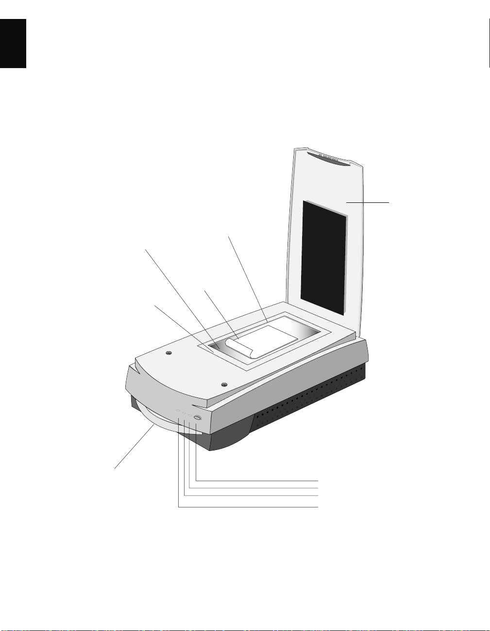
ArtixScan 1100 Scanner
Scanner
cover
Glass surface
Horizontal ruler
Transparency tray
Vertical r uler
Reflective
Material
A
Power switch
Power LED (green)
Reflective Ready indicator (orange)
Transparency Ready indicator
(orange)
2 ArtixScan 1100 Hardware User’s Guide
Page 7
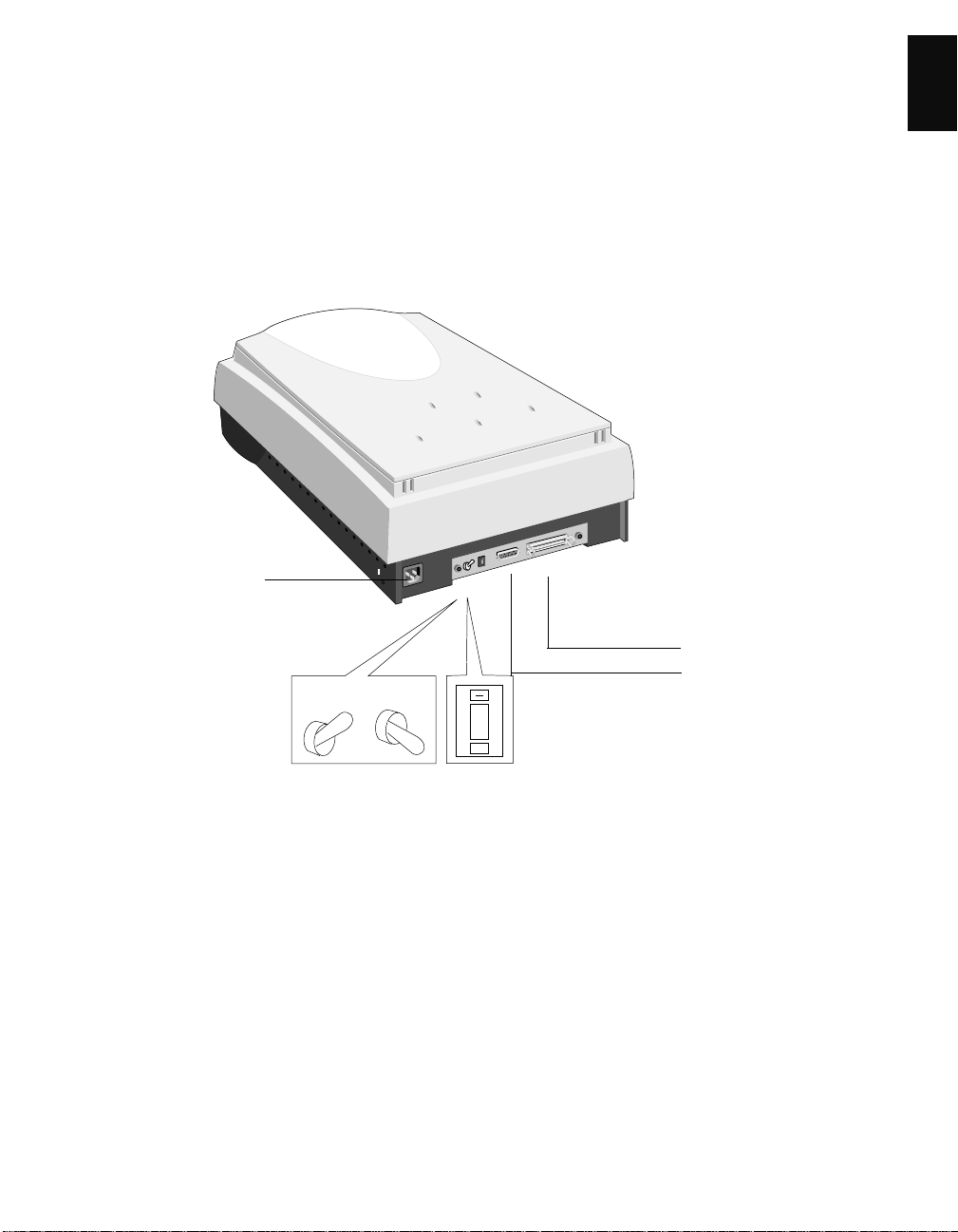
Power connector
Terminator
switch
ArtixScan 1100 Scanner
ON OFF
English
SCSI 50-pin connector
SCSI 25-pin connector
6
+
ID switch
ArtixScan 1100 Hardware User’s Guide 3
Page 8
English
2 General Installation
This section provides information on procedures you need to perform or things to check on your ArtixScan 1100
scanner regardless of the environment in which you operate — whether it is on the Macintosh or on the PC. The
general installation procedures cover the following subjects: 1) unpacking your scanner; 2) unlocking the scanner; 3)
resetting the scanner’s SCSI ID if necessary; 4) powering up the scanner; and 5) choosing your scanning station.
1. Unpacking the Scanner
While unpacking the scanner, inspect the shipping carton
for any signs of mishandling or damage. Your scanner’s
packing carton and padding material has been carefully
chosen to prevent damage to the unit in shipping and can
withstand a reasonable amount of abuse.
Refer to the package contents checklist included with your
scanner to ensure that you received all of the parts
necessary for scanner setup. Should you observe any
damage or missing parts, contact the shipper and your
dealer immediately .
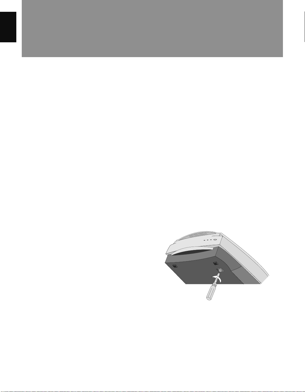
2. Unlocking the Carriage
T o prev ent damage to the scanner’ s moving parts, the
scanner carriage is locked into place prior to shipment.
You must unlock the carriage before powering up the
scanner. Failur e to do so may damage the scanner and will
void your warranty. Follow the unlocking instructions
below:
The carriage lock of the ArtixScan 1100 is located on the
underside of the scanner.
T o unlock the carriage, insert a flathead scre wdriv er or a
coin into the locking screw slot and turn the screw a
quarter turn counter-clockwise. Once unlocked the screw
head will pop out slightly but will remain in the scanner.
Note: The scanner must be relocked prior to any future
scanner transportation or relocation.
4 ArtixScan 1100 Hardware User’s Guide
Page 9
3. Resetting the scanner’ s SCSI ID
Note: This procedure is provided as a reference, and you
may or may not need to change the SCSI ID on your
scanner.
A SCSI ID is assigned to each SCSI device in your daisy
chain to differentiate the devices from one another . The
SCSI ID for your Microtek scanner is factory-set to 6.
You do not need to change the SCSI ID on your scanner
unless another SCSI device on your system (such as an
external hard drive, additional scanner, etc.) is using the
same number.
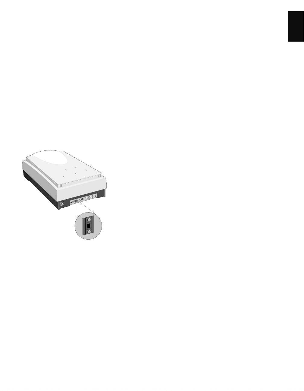
T o change the SCSI ID: Locate the SCSI ID switch, then
press the upper opening “-” to decrease the SCSI ID
number, or press the lower opening “+” to increase the
number.
4. Power-up test
All scanners are factory tested. To ensure that your
scanner has not been damaged during shipment, however,
you will need to perform the following preliminary
power-up test. Contact your dealer immediately if the
scanner is not in proper working condition.
A. Operating Voltage
Your scanner is preset to the voltage in your area. There is
no need to manually select the voltage; however, make
sure that the label next to the power entry module
indicates the correct voltage. Contact your dealer if the
label indicates an incorrect voltage.
B. Connecting the Scanner to Power Source
Caution! Make sure your scanner carriage is unlocked
prior to connecting it to a power source (refer to step 2).
Connect the scanner to a voltage source directly by using
the supplied power cord; do not use extension cords.
Make sure that the power outlet will not be overloaded
when the scanner is turned on, and ensure that other
devices requiring significant power are not plugged into
the same outlet. Ideally, no other de vices should share the
scanner’s po wer source.
English
6
+
Valid SCSI ID number s are 0 to 6. Do not use SCSI ID
#7, which is used to carry out a self-test for the
scanner and make the carriage move back and forth.
SCSI ID #8 and #9 are also not used.
C. Powering up the Scanner
The power switch is located on the scanner’s front panel.
After verifying that the scanner is plugged into a live
outlet, turn on the Power Switch.
ArtixScan 1100 Hardware User’s Guide 5
Page 10

D. Observing the Scanner Boot Process
The following sequence of events should take place after
English
power up:
• The scanner performs a self-test by homing the
carriages and camera box. Through the platen glass,
you will be able to observe the carriage moving, and
you will hear a series of clicking noises associated
with the operation of the scanner motors. These
“clicking” noises are normal. However, if you hear
loud grinding noises or any other abnormal sound,
turn the scanner off immediately and contact your
dealer.
• The Orange indicator light located on the front panel
will flash, indicating that the scanner is running.
• After the self test is complete, the indicator lights
will shine steadily, and the fluorescent lamp inside
the scanner will light up, indicating that the scanner
is ready.
If an error occurs and the scanner is not able to boot up
properly, the status indicators will display a steady red
light in all three indicators. If this happens, turn the
scanner off immediately and contact your dealer.
5. Choosing the Scanning Station
If no errors were encountered and the scanner booted up
normally, you are now ready to set it up. Turn off the
power switches and disconnect the cord.
Before you choose a location for the scanner, please read the operating environment requirements listed
below.
Requirements for the Operating Environment
• Make sure that the operating environment for the
scanner is free of dust and other contaminants.
• Allow adequate ventilation space (no less than ten
inches) around the scanner.
• Place the scanner on a flat, stable surface that is not
subject to vibration.
• Make sure that the scanning surface will not be
exposed to direct sunlight or other sources of bright
light.
• Avoid placing the scanner close to sources of extreme
temperature.
• Try to ensure that the scanner is situated in its ideal
operating temperature range — between 50º and
104ºF (10º and 40ºC).
• Keep the relative humidity in the scanner operating
area between 10% and 85%.
• Avoid connecting the scanner to a power source that
might experience power surges.
• Avoid positioning the scanner in the path of heavy
traffic where it may get bumped.
Once the scanner has been placed in a suitable location
and is ready to be connected to the host computer, it is
time to proceed to installing the necessary hardware and
software components for the scanner. Please go to the
appropriate section in this manual for the installation
procedures to follow, and perform the procedures
corresponding to your environment (Macintosh,
Windows 98 /Windows 95, or Windows NT 4.0).
6 ArtixScan 1100 Hardware User’s Guide
Page 11
3 Installation on the Macintosh
This section provides information on installing the ArtixScan 2020 on the Macintosh. The procedures are divided
into two main sections: 1) Installation for Macintosh computers that feature built-in SCSI ports; and 2) Installation
for the new Macintosh G3 computers (with no SCSI ports). For the new G3 computers, you will be installing the
SCSI interface card included in the scanner package.
A. Installation for Macintosh computers with built-in SCSI ports
English
1. Connecting the scanner
1. Shut down your computer.
2. Connect the scanner to your computer, using the
SCSI cable provided in the scanner package.
Note: See the next section for details on termination.
3. Plug the power cord to the power connector at the
back panel of the scanner, and plug the other end of
the power cord to your AC power source or wall
outlet.
2. Termination
A terminator is included in your scanner package and
should be installed on your scanner in the following
situations:
• If the scanner is the only SCSI device in your SCSI
chain; or
• If you are daisy chaining the scanner with other
SCSI devices AND the scanner is the last device in
your SCSI chain.
Normally, a terminator is not required is when the
scanner is part of a daisy chain and is NOT the last
device in the SCSI chain.
To install the terminator, plug it into
the SCSI port at the back of the
scanner (beside the cable connecting
the scanner to the computer).
4. Turn on your scanner and wait for all the lights on
the front panel to stop blinking and stay on steady.
5. Power up your Macintosh.
ArtixScan 1100 Hardware User’s Guide 7
Page 12
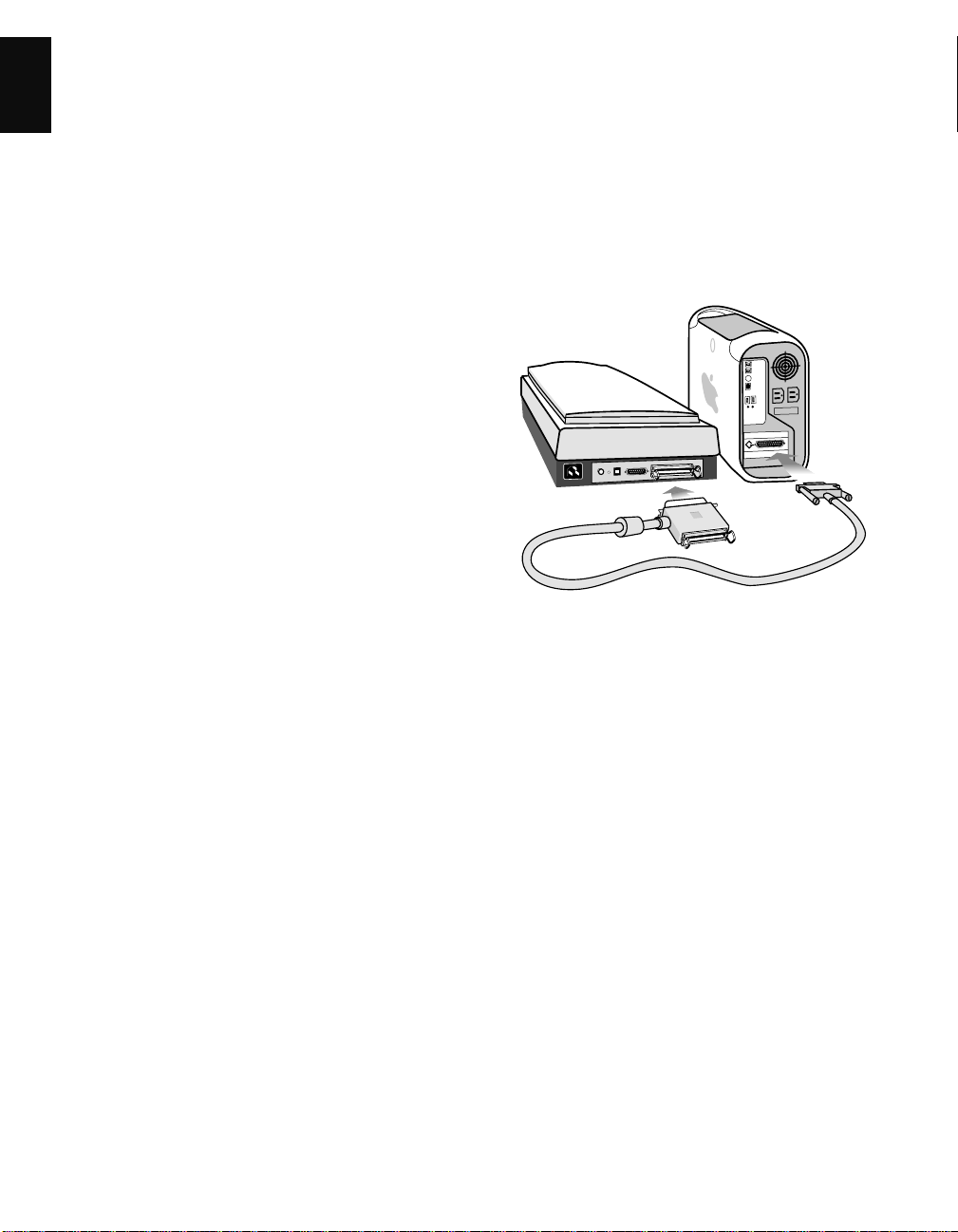
B. Installation for the new G3 Macintosh computers (without built-in SCSI ports)
English
1. Installing the interface card
2. Connecting the scanner
Before installing the interface card, make sure you turn
off your computer and peripherals. Then follow the steps
below:
1. Shut down your computer and unplug the power
cord. Next, open your computer.
2. Look for an available PCI card slot (typically white
or ivory) in your computer. Remove the slot cover,
and insert the Adaptec PCI SCSI card into the slot.
Push the card in to make sure it is seated all the way
in the slot. This is important, as an improper card
connection will make you unable to use your scanner,
and you will then have to remove the computer case
and reinsert the card.
3. Close the computer, then plug the power cord back
in.
1. Shut down your computer .
2. Connect the scanner to your computer, using the SCSI
cable provided in the scanner package.
Note: See the next section for details on termination.
3. Plug the power cord to the power connector at the
back panel of the scanner, and plug the other end of
the power cord to your AC power source or wall
outlet.
8 ArtixScan 1100 Hardware User’s Guide
4. Turn on your scanner and wait for the lights on the
front panel to stop blinking and stay on steady.
5. Power up your Macintosh.
Page 13

3. Termination
A terminator is included in your scanner package and
should be installed on your scanner in the following
situations:
• If the scanner is the only SCSI device in your SCSI
chain; or
• If you are daisy chaining the scanner with other
SCSI devices AND the scanner is the last device in
your SCSI chain.
Normally, a terminator is not required is when the
scanner is part of a daisy chain and is NOT the last
device in the SCSI chain.
To install the terminator, plug it into
the SCSI port at the back of the
scanner (beside the cable connecting
the scanner to the computer).
C. Installing the software
Install all the software in your Artix CD-ROM.
To do this, insert the Artix CD-ROM into your CD-ROM
drive. When the CD-ROM icon appears on your
Macintosh desktop, open the software folders individually, then double-click the Installer icon on each folder
to install the respective programs one at a time.
English
ArtixScan 1100 Hardware User’s Guide 9
Page 14

English
4 Installation on Windows 98 / 95
1. Installing the interface card
1. Turn off your PC and peripherals, and unplug the
power cord. Next, remove the cover from your
computer.
2. Before handling the interface card, touch a metal
frame (such as your computer casing) to discharge
any static electricity buildup in your body.
3. Look for an available PCI card slot in your computer,
then insert the Adaptec PCI SCSI card (such as the
Adaptec AVA-2903E or 2906E) into the slot. Push
the card in to make sure it is seated all the way in the
slot, then put the screw back into the bracket.
Proper card connection is important, as an improper
card connection will make you unable to use your
scanner, and you will then have to remove the
computer case and start the process of card insertion
all over again.
SCSI card
2. Checking the interface card status
When Windows starts with the Adaptec SCSI card
installed in your computer, the card is detected and the
driver automatically installed. You may be asked to
insert your Windows CD-ROM. Do so, and follow the
steps below to check your card status.
1. In Windows, click Start, Settings, and then select
Control Panel.
2. Double-click on the System icon in Control Panel
and select Device Manager from the top.
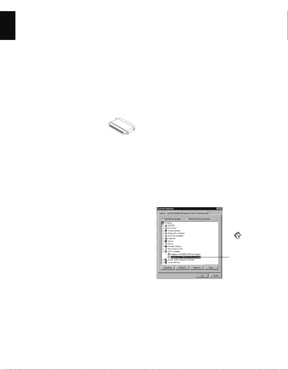
3. Double-click on SCSI controllers to display the
screen below. The string “Adaptec 7850 PCI SCSI
Controller” indicates that the driver is installed.
The result of
the check is
displayed
here
4. Replace the cover of the computer, then plug the
power cord back in.
5. Turn your PC back on.
10 ArtixScan 1100 Hardware User’s Guide
The message “Adaptec AIC-7850 PCI SCSI
Controller” displays indicates that the driver is
installed and that the interface card works properly.
If a conflict exists, either of the following will occur:
• a yellow exclamation mark appears next to the
phrase:
Adaptec AIC-7850 PCI SCSI Controller
- or -
• nothing is listed under “SCSI Controllers”. In
either case, refer to the Troubleshooting section.
Page 15

3. Installing the software
Install all the software in your Artix CD-ROM, w hich
includes Microtek ScanWizard Pro and the Microtek
Scanner ICC Profiler programs.
To do this: Insert the Artix CD-ROM into your CDROM drive; the Scanner Software installer should come
up automatically.
Note: If the Scanner Software is not automatically
displayed, click Start, select Run and type d:\cdsetup
(where d: is your CD-ROM drive).
Click on the “Install” option on each software program
in the order that it appears on your screen to install the
software.
During installation of ScanWizard Pro, make sure you
choose Adaptec SCSI Interface Card as your interface
type.
After all the software has been installed, shut down your
computer.
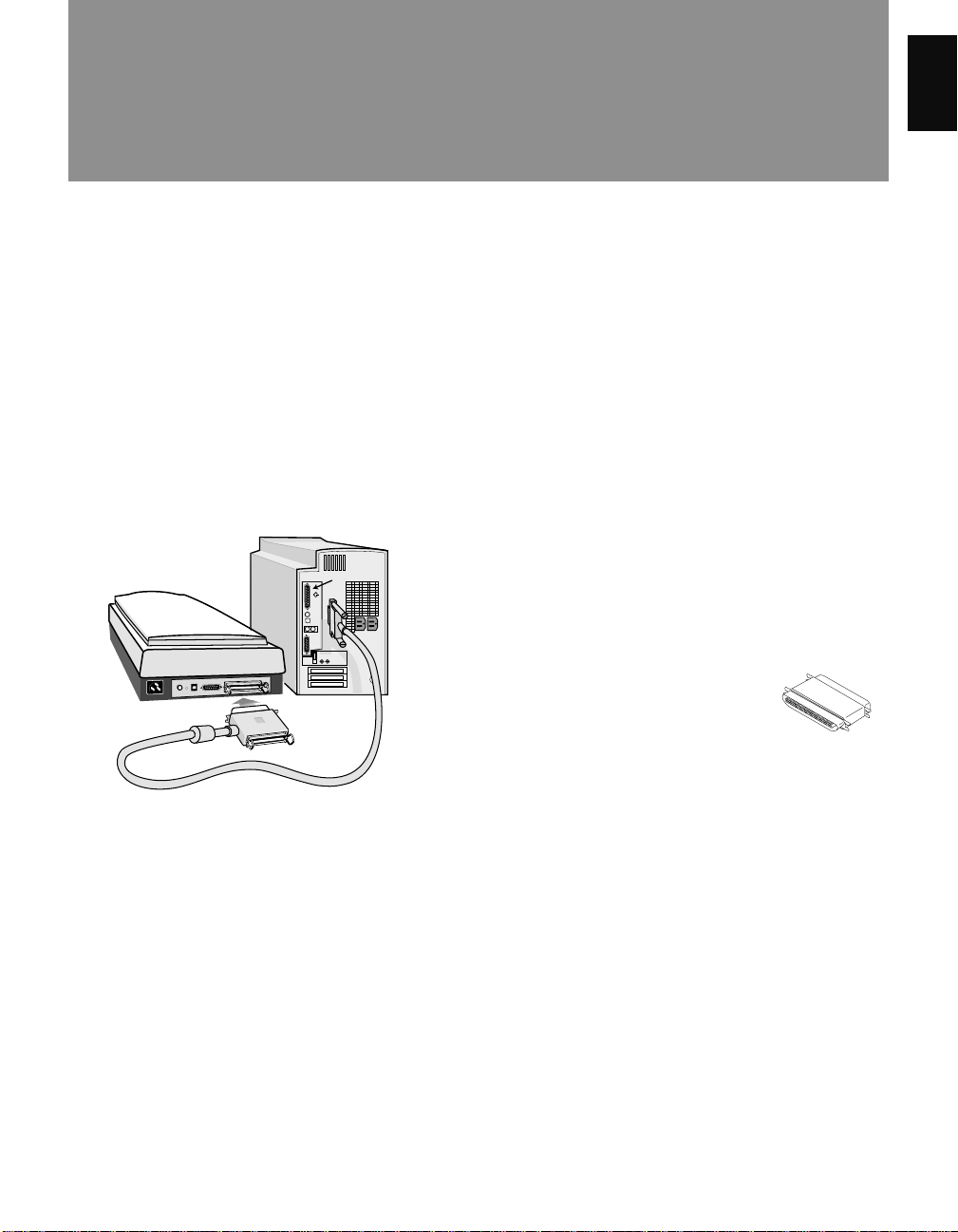
4. Connecting the scanner
1. Turn off your PC.
2. Plug the 25-pin end of the SCSI cable into the
Adaptec card at the back of the computer. Then plug
the 50-pin end of the SCSI cable into the back of the
scanner.
Note: See the next section for details on termination.
3. Plug the power cord into the back of the scanner and
plug the other end of the power cord into a power
source or wall outlet.
English
4. Press the scanner’s power button on the front panel to
turn the power on, then wait for the Ready indicator
lights also on the front panel of the scanner to stop
blinking and to stay on solid.
5. Turn your PC back on. When Windows starts up, it
will automatically detect the scanner.
ArtixScan 1100 Hardware User’s Guide 11
Page 16
5. Termination
English
A terminator is included in your scanner package and
should be installed on your scanner in the following
situations:
• If the scanner is the only SCSI device in your SCSI
chain; or
• If you are daisy chaining the scanner with other
SCSI devices AND the scanner is the last device in
your SCSI chain.
Normally, a terminator is not required is when the
scanner is part of a daisy chain and is NOT the last
device in the SCSI chain.
6. Troubleshooting
After installing the interface card in your computer and
connecting the scanner, you may find yourself unable to
use the scanner. This is usually due to any of the
situations described below:
Situation A Your interface card is not properly seated
in the PCI card slot on your computer.
Situation B Your interface card conflicts with another
device.
Situation C Windows 98 / 95 cannot recognize your
interface card.
To install the terminator, plug it into
the SCSI port at the back of the
scanner (beside the cable connecting
the scanner to the computer).
Resolving situation A
Power off your computer, then remove the interface card
from your computer. Re-install it and make sure the card
is seated all the way in and secured into the PCI card
slot.
Resolving situation B
1. Click Start, Settings, and select Control Panel.
2. Double-click on the System icon in Control Panel
and select Device Manager from the top.
3. Double-click on “SCSI controllers” to display the
dialog box below.
A yellow
exclamation
mark appears
next to the
message
“Adaptec AIC7850 PCI SCSI
Controller”.
4. Click on the Adaptec AIC-7850 PCI SCSI Controller option, and then click Properties.
12 ArtixScan 1100 Hardware User’s Guide
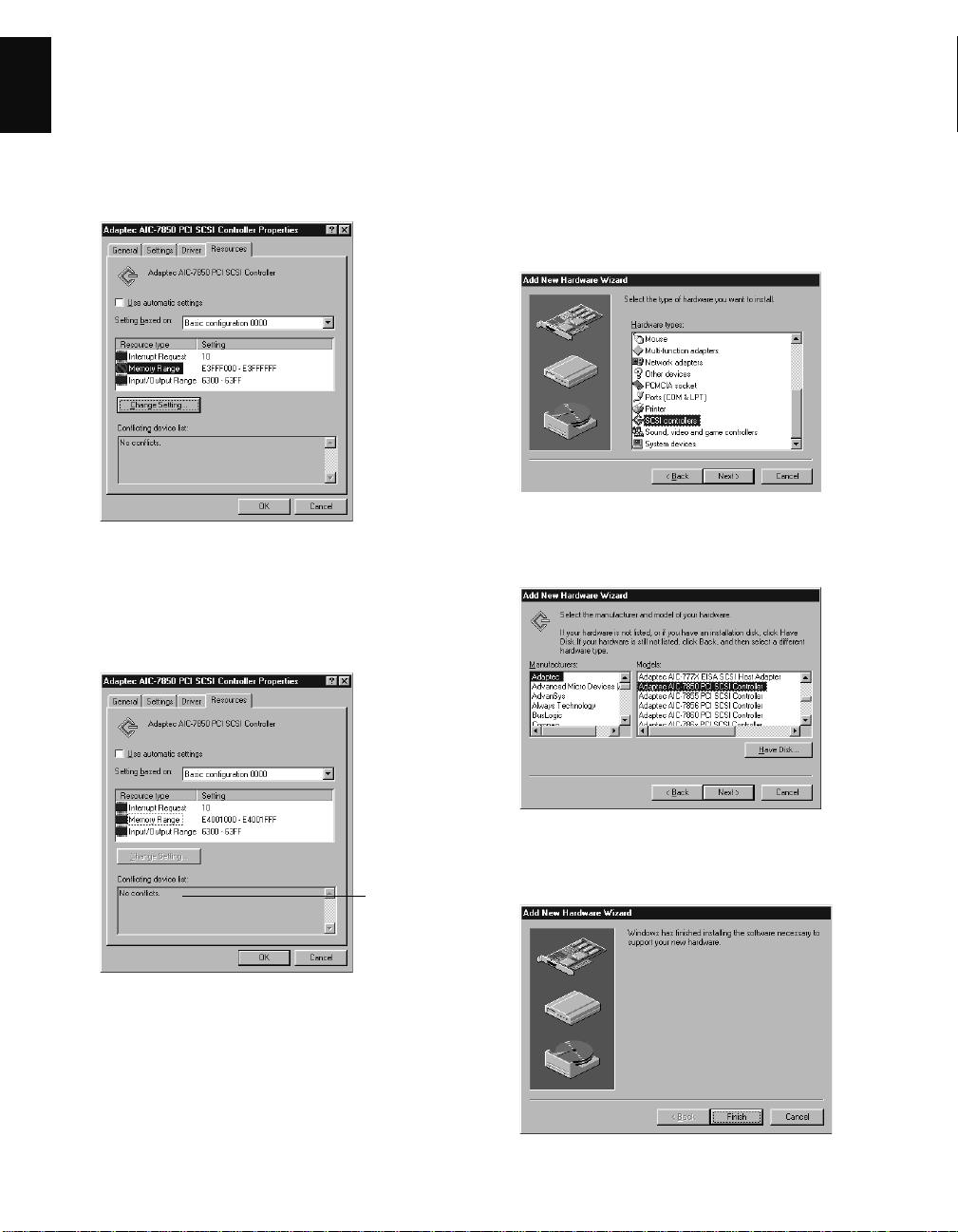
5. Select Resources from the top. The dialog box gives
you information about the 3 resources: Interrupt
Request (IRQ), Memory Range, and Input/Output
range. Any conflict in the 3 resources is detected and
displayed in the “Conflicting device list”.
Page 17
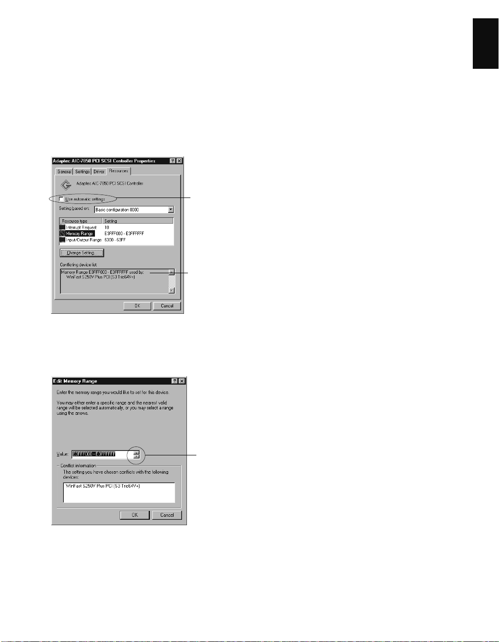
6. To resolve the conflict, uncheck “Use automatic
settings”, then click to modify the individual
resource, one after another, until the message “No
conflicts” appears in the Conflicting device list.
For example, to resolve the Memory Range conflict,
take these steps:
a) At the Resource type, double-click on the
Memory Range string, the Edit Memory Range
dialog box is displayed.
Uncheck
this option
Error
message
appears
here if
conflict
occurs
English
b) When the next screen appears, go to the Value
box, then use the Up/Down arrow keys to select
a different range.
Click the
arrows to
select a
different
range
ArtixScan 1100 Hardware User’s Guide 13
Page 18
7. When you get a “No conflicts” message in the
English
Conflicting device list, the Memory Range conflict is
resolved. Take similar steps for the Interrupt Request
(IRQ) and Input/Output Range resources. If all of
IRQs are taken, you need to contact your computer
dealer for help on how to free up an IRQ for you.
8. When the settings are all correct, click OK to save the
modifications. The dialog box should now show the
correct Interrupt Request, Memory Range, and Input/
Output address settings.
Resolving situation C
1. Click Start, Settings, and select Control Panel.
2. Double-click Add New Hardware.
3. Click Next and select No for “Do you want Windows
to search for your new hardware?”.
4. From the next menu, select SCSI controllers and
click Next.
5. Select Adaptec on the left and “Adaptec AIC-7850
PCI SCSI Controller” on the right. Click Next.
No conflicts
found
If you are asked to shut down your computer, select
No, then click Close. You will be asked whether you
wish to restart your computer. Click Yes and restart
your computer.
14 ArtixScan 1100 Hardware User’s Guide
6. When the “Add New Hardware Wizard” dialog box
appears, click Finish.
Page 19

7. When installation is complete, Windows will ask if
you wish to shut down your computer. Select No.
8. Click Start, Settings, and select Control Panel.
9. Double-click on the System icon in Control Panel
and select Device Manager from the top.
10. Double-click on “SCSI controllers” to check
whether conflict happens. If a conflict exists, follow
the steps in Resolving Situation B.
11. When the settings are all correct, click OK to save the
modifications. The dialog box should now show the
correct Interrupt Request, Memory Range, and Input/
Output address settings. If you are asked to shut
down your computer, select No, then click Close.
You will be asked whether you wish to restart your
computer. Click Yes and restart your computer.
English
ArtixScan 1100 Hardware User’s Guide 15
Page 20
English
5 Installation under Windows NT 4.0
1. Installing the interface card
See page 10 for details. Card installation on
Windows NT 4.0 is the same as that under
Windows 98 / 95.
2. Installing the Windows NT driver
a) Start your computer, and log in as Administra-
tor. Note: You must be logged in as Administra-
tor in order to install the scanner software
components and use the scanner.
b) In Windows, go to Start, Settings, then
double-click on Control Panel, and doubleclick on the SCSI Adapters icon.
c) Select the Drivers tab in the SCSI Controllers
dialog box, and click on the Add button.
d) From the list of drivers that appear, select
Adaptec for manufacturers on the left, and
Adaptec AIC-78xx PCI SCSI Controller on
the right. You may be asked to insert your
Windows NT CD-ROM at this point; do so.
e) You will be asked to restart your computer.
Click Yes to do so.
3. Installing the software
Make sure you have logged in as Administrator.
Then see page 11 for more details. The software
installation instructions for your scanner under
Windows NT 4.0 are the same as those for
installation under Windows 98 / 95.
6. Troubleshooting
After installing the interface card in your computer and
connecting the scanner, you may find yourself unable to
use the scanner. This is usually due to any of the
situations described below:
Situation A Your interface card is not properly seated
in the PCI card slot on your computer.
Situation B The driver for the interface card is not
properly installed on your computer.
Resolving situation A
Power down your computer, remove the interface card
from your computer. Then re-install it, make sure the
card is seated all the way in and secured into the PCI
card slot.
Resolving situation B
1. Restart your computer.
2. In Windows 4.0, click Start, Settings, and select
Control Panel.
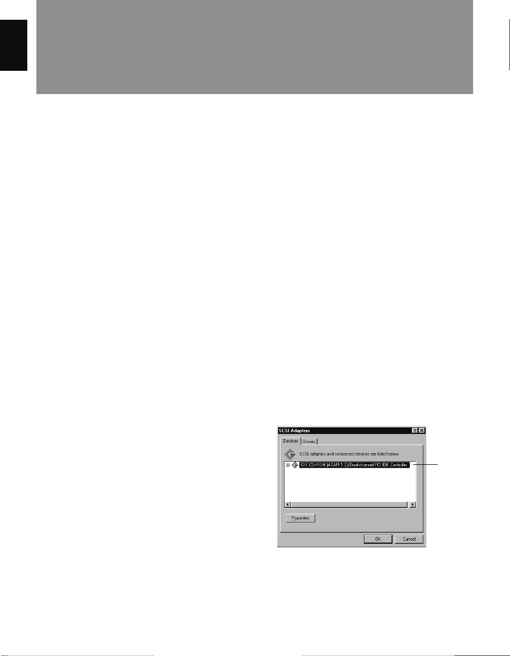
3. In the Control Panel window, find SCSI Adapters
and double click it. A window like the following
below will appear.
4. Connecting the scanner
See page 2-4 for details. Connecting the scanner
on Windows NT 4.0 is the same as that under
Windows 98 / 95.
5. Checking the scanner status
a) Double-click the SCSI Adapters icon in
Control Panel; the string Adaptec AIC-78xx
PCI SCSI Controller should appear on the
list.
b) Double-click on this option, and it should
expand with the scanner listed below it. Close
all dialog boxes to continue.
16 ArtixScan 1100 Hardware User’s Guide
Adaptec
SCSI driver
is not listed
here
.
The Devices screen will list any SCSI controllers that
may already have been installed in your computer.
Note: IDE CD-ROM drives are not SCSI, but
Windows NT 4.0 will still list it on the screen because
Page 21

of the way the driver is implemented
4. Click on the Drivers tab, and click on the Add button
to select Adaptec on the left and “Adaptec AIC-7800
PCI SCSI Controller” on the right.
5. Click OK to bring up the following screen. The
Adaptec card should now be listed as “Adaptec AIC7800 PCI SCSI Controller”, indicating the driver is
installed.
English
6. Restart your computer.
ArtixScan 1100 Hardware User’s Guide 17
Page 22
English
6 Operating the Scanner
This section provides information on how to operate the ArtixScan 1100. The subjects covered in this section include
how to position your images for scanning and how to use the various holders included in your scanner package when
scanning transparent film.
1. Positioning reflective materials
This procedure applies when you use the upper scan bed of the ArtixScan 1100. The upper scan bed is used for
scanning reflective materials such as photos and prints.
A. General scanning
1. Lift the scanner lid.
2. Place the image to be scanned face down on the
scanner glass. Center the top of the image at the “0”
position along the horizontal ruler on the scanner.
Then lower the scanner lid.
“0” mark is in the
middle of the
horizontal ruler
A
B. Scanning thick documents
To scan thick documents, lift the scanner lid high
enough so that there is room to place the document on
the scanner glass. Then lower the scanner lid.
18 ArtixScan 1100 Hardware User’s Guide
Page 23

2. Positioning transparent film
This procedure applies when you use the lower scan bed of the ArtixScan 1100, which has a transparency tray that is
used for scanning transparent film.
There are two ways to scan transparent film: 1) By using the Universal Glass Film Holder; or 2) By using the Main
Holder with the various other holders also included in your scanner package. See below for more details.
English
Using the Universal Glass Film Holder
Use the Universal Glass Film Holder together with the
transparency tray when you wish to scan non-standardsized transparent film.
Universal
Glass Film
Holder
Using the Main Holder with other film holders
Use the Main Holder with other film holders for
scanning a particular type of standard-sized film. For
instance, use the 4” x 5” Film Holder to scan 4” x 5”
film, or use the 35mm Filmstrip Holder to scan 35mm
filmstrips.
Main Holder
35mm Slide Holder 35mm Filmstrip Holder
4” x 5” Film Holder 6x9 cm Film Holder
ArtixScan 1100 Hardware User’s Guide 19
Page 24

A. Using the Universal Glass Film Holder
English
1. To scan non-standard-sized transparent film, place
the film face down on top of the glass surface of the
Universal Glass Film Holder.
2. To secure the film to the Universal Glass Holder,
place the vinyl strip on the edge of the transparency.
3. Insert the Universal Glass Film Holder into the
transparency bay (the drawer or lower compartment)
of the scanner.
20 ArtixScan 1100 Hardware User’s Guide
Page 25

B. Using the 35mm Slide Holder
1. Insert the individual 35mm slides to be scanned into
the 35mm Slide Holder.
2. Place the 35mm Slide Holder in the Main Holder.
English
3. Insert the whole assembly into the transparency bay
(the drawer or lower compartment) of the scanner.
ArtixScan 1100 Hardware User’s Guide 21
Page 26

C. Using the 35mm Filmstrip Holder
English
1. Insert the 35mm filmstrip to be scanned into the
35mm Filmstrip Holder.
a) Push to open the 5-piece 35mm filmstrip holder.
b) Place the 35mm filmstrip in the holder.
2. Place the 35mm Filmstrip Holder in the Main Holder.
35mm
Filmstrip
Holder
Main
Holder
3. Insert the whole assembly into the transparency bay
(the drawer or lower compartment) of the scanner.
c) Pull to close the 5-piece 35mm filmstrip holder.
22 ArtixScan 1100 Hardware User’s Guide
Page 27

D. Using the 6 x 9 cm Film Holder
1. Insert the film to be scanned into the 6 x 9 cm Film
Holder.
a) Push on the side to open the holder.
2. Place the 6 x 9 cm Film Holder in the Main Holder.
English
6 x 9 cm
Film
Holder
Main
Holder
b) Place the film in the holder.
c) Pull the side down to close the holder.
3. Insert the whole assembly into the transparency bay
(the drawer or lower compartment) of the scanner.
ArtixScan 1100 Hardware User’s Guide 23
Page 28

E. Using the 4" x 5" Film Holder
English
1. Insert the film to be scanned into the 4" x 5" Film
Holder.
a) Push on the side to open the holder
2. Place the 4”x5” film holder in the Main Holder .
4” x 5”
Film
Holder
Main
Holder
b) Place the film in the holder.
c) Pull down the side to close the holder .
3. Insert the whole assembly into the transparency bay
(the drawer or lower compartment) of the scanner .
24 ArtixScan 1100 Hardware User’s Guide
Page 29

7 Using the Scanner ICC Profiler Program
English
1. Introduction
The Scanner ICC Profiler is a scanner calibration and
profiling utility program designed exclusively for use
with Microtek scanners, including the ArtixScan 1100.
The Scanner ICC Profiler lets you calibrate the color
attributes of your scanner and lets you create an ICC
color profile customized and tailored especially for your
Microtek and Artix scanner .
Why do you need the Scanner ICC Profiler?
For each Microtek and Artix scanner, a generic factory-set
ICC color profile is built in and included for use with the
scanner controller program — in this case, ScanWizard
Pro. This factory-set profile delivers high color quality in
general. But scanners, like any high-end device, interpret
colors differently , resulting in subtle variations and
differences in color imaging. In addition, individual
scanners may also perform different due to other factors,
such as aging of the scanner lamp or ambient temperature.
With the Scanner ICC Profiler, such color variations and
differences can be minimized or eliminated, as the
program calibrates the scanner and compensates for subtle
color deviations. The customized color profile resulting
from the use of the Scanner ICC Profiler, in effect,
delivers more accurate color and contributes to overall
improved image quality .
T o keep the colors in your scanner consistent over time,
it’s recommended that you use the Scanner ICC Prof iler
regularly . Professional photographers or others w ho
require extremely precise color may wish to use the
Profiler every time before they use their scanner, but for
most general usage, calibrating twice a month should be
sufficient.
2. Calibration target
Your Scanner ICC Profiler kit includes two industrystandard IT8 color targets for calibration.
• Kodak Q-60R1: This is a reflective target for calibrating
the upper scan bed. Calibrating the upper scan bed
ensures color accuracy when you scan reflective
materials such as photos and prints.
• Kodak Q-60E1: This is a transparent target for
calibrating the lower scan bed. Calibrating the lower
scan bed ensures color accuracy when you scan
transparent media such as slides and filmstrips.
3. T aking care of the target
The calibration target is very delicate and must be handled
carefully. Mak e sure you follow these rules in caring fo r
the target.
• Gently take the target out of its protective sleeve.
• Do not touch the target image with your fingers or with
any other object.
• When not in use, keep the target out of light — even
interior lighting.
• Alw ays return the target to its protecti v e sleev e
immediately after use.
• Store the target away from light in a cool, dry place,
since long exposure to heat and light can change the
colors on the target.
4. Replacing the target
With proper care, your target should hold its original
colors for about a year or so starting from the date of use.
After that, it will begin to fade, as is the nature of most
photographic materials. The change may be unnoticeable
to the naked eye, but even very slight changes in the target
decrease the performance of the Scanner ICC Profiler . T o
maintain color accuracy , Artix recommends that you
replace the target once a year, or when you notice a loss
of image quality in your scanned images.
ArtixScan 1100 Hardware User’s Guide 25
Page 30

5. Installing the Scanner ICC Profiler
English
Note: The Scanner ICC Prof iler program should have
been installed at the time you performed software
installation procedur es (discussed earlier in the manual).
If for some reason you have not installed the Scanner
ICC Profiler, follow the steps below to install the
program.
A. For the Macintosh
Before installing the Scanner ICC Profiler, you should
have ScanWizard Pro and the Kodak CMS programs
installed on your computer.
T o install the Scanner ICC Profiler program: Insert the
Artix CD into your CD-ROM drive. Open the ICC
Profiler folder, then double-click the Installer icon to
install the program.
B. For Windows 98 / 95 / NT 4.0
Before installing the Scanner ICC Profiler, you should
have ScanWizard Pro and the Kodak CMS programs
installed on your computer.
T o install the Scanner ICC Profiler program: Insert the
Artix CD into your CD-ROM drive. When the Software
Installer screen appears, click on the “Install” option for
the Scanner ICC Profiler program, then follow the onscreen instructions until the program finishes installing.
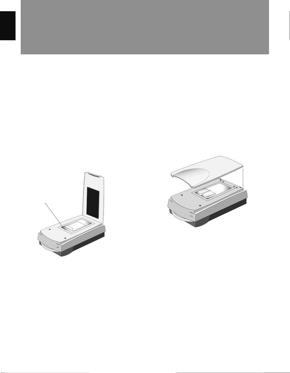
6. Placing the color target
• Positioning the target in the upper bed: Place the
reflective color target in the upper scan bed and make
sure it is positioned correctly, following the
illustration below . See the additional notes in the next
section for important notes on how to position the
reflective target correctly on the upper bed. Then
proceed to the calibration procedures discussed in the
succeeding pages to calibrate the upper scan bed.
• Positioning the target in the lower bed: After
completing the entire calibration process for the
upper bed (detailed in the next few pages), return to
this section to see how to position the transparency
target correctly on the lower scan bed. Then proceed
again to the calibration procedures discussed in the
next pages to calibrate the lower scan bed.
26 ArtixScan 1100 Hardware User’s Guide
Positioning the target on the upper scan bed
Positioning the target on the lower scan bed. In
the example above, the target is placed in the 4”
x 5” Film Holder, and the Holder is then placed
into the transparency tray of the lower scan bed.
Page 31

7. Calibration
1. Turn on your scanner and let it warm up for about
five minutes.
2. Place the target inside the scanner.
3. Launch the Scanner ICC Profiler calibration utility.
The screen below appears.
A
C. Click on the Start Calibrate button. The calibration
window will appear, and an initial preview is
performed.
C
English
Initial
preview
B
A. Choose the media type. Select Reflective to calibrate
in reflective mode, or select Positive to calibrate in
transparency mode.
B. Select the target type that matches your target type
and date code. You can verify this information by
looking at the bottom of the target for the date code
and the target type information.
Scan button
Preview button
8. Scanning the target image
Following the Preview, a message appears informing you
of the next step to be done.
To select the target image, move the pointer (now a
crossbar) to the preview image, and draw a frame
enclosing the entire target image. When you release the
mouse, a scan frame appears, which is the dotted
marquee enclosing the target image.
Scan frame
encloses target
image
ArtixScan 1100 Hardware User’s Guide 27
Page 32

To resize the selection, move the cursor to any corner of
the frame; the pointer is changed to a double-headed
English
arrow. Hold down the mouse, drag to form a new
selection, then release the mouse.
When the target image is selected, click the Scan button
to scan the target.
C. Aligning the bottom-right registration mark
After the upper right mark is aligned, the lower right
part of the target image is displayed, and an instruction
dialog box prompts you to align the bottom right
registration mark.
9. Aligning the target registration marks
A. Aligning the upper-left registration mark
Move the cursor into the target image area; the pointer
will change to a flipped L mark (“ ”). Align the cursor
with the small upper-left registration mark.
Upper left
registration mark
B. Aligning the upper-right registration mark
After the upper left mark is aligned, the upper right part
of the target image is displayed, and an instruction
dialog box prompts you to align the upper right
registration mark.
Bottom right
registration mark
Move the cursor into the target image area; the pointer
will change to a vertically flipped L mark (“ ”).
Align the cursor with the small bottom-right registration
mark.
Upper right
registration mark
Move the cursor into the target image area; the pointer
will change to a normal L mark (“ ”). Align the cursor
with the small upper-right registration mark.
28 ArtixScan 1100 Hardware User’s Guide
Page 33
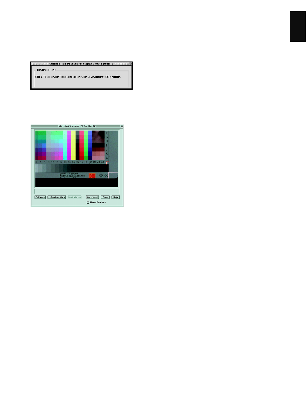
10. Creating a profile
Following the alignment of registration marks, an
instruction dialog box appears, prompting you to click
the Calibrate button.
Click the Calibrate button. This only takes a few
moments. When the process is finished, a message
appears, giving you the results.
English
• If the process was successful, a custom scanner ICC
profile is saved automatically to your system’s
ColorSync Profiles folder. Exit the Scanner ICC
Profiler now, and use the new scanner profile with
ScanWizard Pro to scan excellent color images.
• If the process fails, you will need to rescan the target
image and repeat the calibration procedure described
in the preceding pages. Make sure the registration
marks are aligned properly, then click the Calibrate
button again to create your profile.
ArtixScan 1100 Hardware User’s Guide 29
Page 34

11. Reference Section for Macintosh
English
This section describes the features and commands of the Microtek Scanner ICC Profiler program. All features are
covered in the Menu commands, the Main window, and the Calibration window.
A. Menu commands
1. Apple Menu — About ICC Profiler: Choose the
About ICC Profiler command from your Apple menu
to display the splash screen for the Scanner ICC
Profiler program. The screen includes the product
logo and the software version number
2. Scanner Menu: The Scanner Menu lets you see
information on your current scanner and your SCSI
chain.
a) Find Plug-in: This command lets you choose the
correct ScanWizard Pro Plug-in driver for the ICC
Profiler program (in case the Plug-in driver cannot
be found).
b) Get Current Scanner Info: This command
provides information on the current scanner. A
dialog box appears showing the scanner model in
use, the SCSI ID number of the scanner, and the
firmware version of the scanner.
c) Scanner Probe: This command displays the SCSI
devices on the SCSI chain, as well as the SCSI ID
numbers of the individual devices.
To use this command:
1. Choose the Get SCSI Chain Info command.
.
2. If your scanner does not show in the list, make
sure it is connected and turned on, then click on
the Probe button in the dialog box.
• Choose the correct interface card in the card
selection box.
• Check the numbered box corresponding to
the SCSI ID of your scanner. Click OK to
close the dialog box
30 ArtixScan 1100 Hardware User’s Guide
Page 35
B. The Main Window
The Main window provides various features and a
system menu, allowing you to control the calibration
process.
Controls:
1. Scanner Model: This option lets you select the scanner
to be calibrated.
2. Media: This option lets you select the media type for
calibration. If a particular media is not supported, that
media will not appear on the list.
3. T arget type: This option lets you select the Target
Description File (TDF) that matches your Q-60E3
calibration target being used for calibration.
Note: The Target Description File (TDF) contains
colorimetric measurements of the target. Each target
lot contains unique colorimetric data, and the Scanner
ICC Profiler e valuates the scanned RGB data of the
target and then matches it to the colorimetric data
inside the TDF to create an ICC color profile — a
characterization of how your scanner “sees” color.
4. T onal Mapping: This option lets y ou select the way in
which the tonal reproduction curve of the profile is
controlled.
• Normal: Slightly brightens the highlights but also
darkens the shadows.
• Lighten: Brightens the highlights and also lightens
the image overall.
• Darken: Darkens the shadows without changing
the highlights.
• Reduce Contrast: Captures as much of the original
as possible. Recommended for CMYK color
separation.
5. Darken Shadow: This option lets you compensate for
artifacts introduced by the scanner that indicate
problems with the shadow portion of the image. You
should enable this option if you wish to:
• Minimize detail in the shadow areas of the image;
• Make the shadow areas of an image darker; or
• Reduce the appearance of noise in the shadow
areas.
6. Start Calibration: This button starts the calibration
process by displaying the calibration window and
guides you through the process to create a customized
scanner ICC profile.
7. Close: This button lets you close and exit the Scanner
ICC Profiler.
8. Help: This button displays the Help window.
English
ArtixScan 1100 Hardware User’s Guide 31
Page 36

C. The Calibration Window: Preview and Scan D. The Calibration Window: Aligning targets and
English
1. Preview: The Preview button performs a preliminary
scan of the target, displaying the entire target image in
the calibration window .
2. Scan: The Scan button scans the target image and
prepares the scanner for the important succeeding
steps of aligning the registration marks and creation of
the profile.
creating the profile
1. Calibrate: This button starts the actual calibration
process in which a custom scanner ICC profile is
created for the scanner. This b utton is grayed out until
you have performed the required alignment of the three
registration marks on the target.
2. Previous Mark: This button lets you go back one step
to align the previous registration mark.
3. Next Mark: This button lets you go forward one step
to align the next registration mark.
4. Go to Step 1: This button takes you back to the
preview image screen so that you can rescan the target
image and restart the calibration process.
5. Show Patches: This option lets you check the
sampling area of all the color patches. When aligned
properly, the sampling area appears as a green square
in the center of most patches. If any areas fall outside a
patch, realign the registration marks by clicking the
“Previous Mark” and “Next Mark” buttons, and then
reselecting the registration marks until the sampling
areas are centered.
6. Close: This button lets you return to the main screen
32 ArtixScan 1100 Hardware User’s Guide
Page 37

12. Reference section for PC
This section describes the features and commands of the
Microtek Scanner ICC Profiler program. All features are
covered in the Main window and Calibration window.
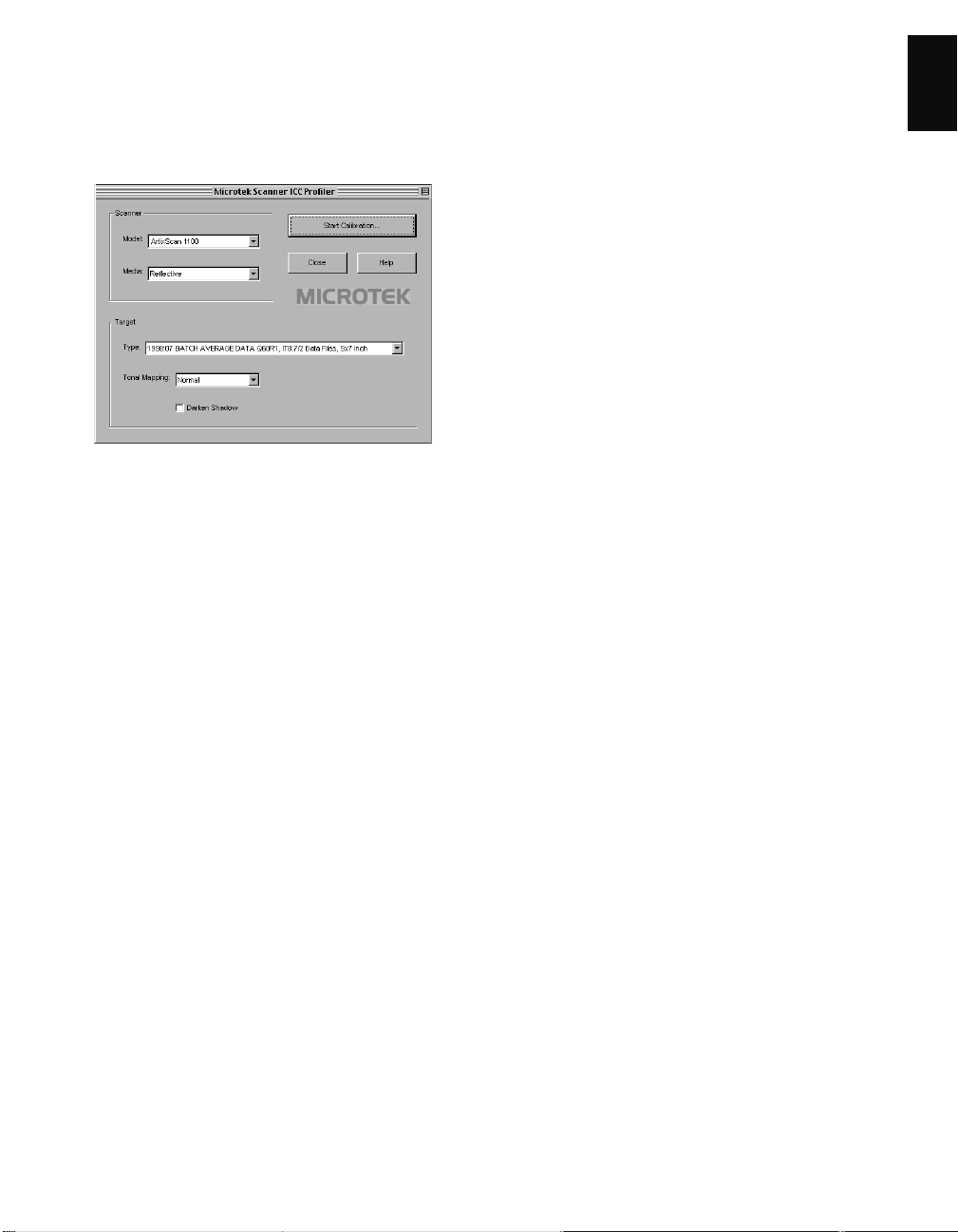
A. The Main Window
The Main window provides various features and a
system menu, allowing you to control the calibration
process.
Controls:
1. Scanner Model: This option lets you select the
scanner to be calibrated.
2. Media: This option lets you select the media type for
calibration. If a particular media is not supported,
that media will not appear on the list.
3. Target type: This option lets you select the Target
Description File (TDF) that matches your Q-60E3
calibration target being used for calibration.
Note: The Target Description File (TDF) contains
colorimetric measurements of the target. Each target
lot contains unique colorimetric data, and the
Scanner ICC Profiler evaluates the scanned RGB
data of the target and then matches it to the colorimetric data inside the TDF to create an ICC color
profile — a characterization of how your scanner
“sees” color.
4. Tonal Mapping: This option lets you select the way
in which the tonal reproduction curve of the profile is
controlled.
• Normal: Slightly brightens the highlights but also
darkens the shadows.
• Lighten: Brightens the highlights and also
lightens the image overall.
• Darken: Darkens the shadows without changing
the highlights.
• Reduce Contrast: Captures as much of the
original as possible. Recommended for CMYK
color separation.
5. Darken Shadow: This option lets you compensate for
artifacts introduced by the scanner that indicate
problems with the shadow portion of the image. You
should enable this option if you wish to:
• Minimize detail in the shadow areas of the image;
• Make the shadow areas of an image darker; or
• Reduce the appearance of noise in the shadow
areas.
6. Start Calibration: This button starts the calibration
process by displaying the calibration window and
guides you through the process to create a customized scanner ICC profile.
7. Close: This button lets you close and exit the Scanner
ICC Profiler.
8. Help: This button displays the Help window.
English
ArtixScan 1100 Hardware User’s Guide 33
Page 38

System Menu:
The System Menu displays current scanner information,
English
lets you view the SCSI chain status, and lets you view
the About dialog box of the Scanner ICC Profiler
program.
1. Get Current Scanner Info: This command provides
information on the current scanner. A dialog box
appears showing the scanner model in use, the SCSI
ID number of the scanner, and the firmware version
of the scanner.
2. Scanner Probe: This command displays the SCSI
devices on the SCSI chain, as well as the SCSI ID
numbers of the individual devices.
To use this command:
1. Choose the Get SCSI Chain Info
command.
2. If your scanner does not show in the
list, make sure it is connected and
turned on, then click on the Probe
button in the dialog box.
• Choose the correct interface card
• Check the numbered box
in the card selection box.
corresponding to the SCSI ID of
your scanner. Click OK to close
the dialog box.
3. About: This command displays the splash screen of
the Scanner ICC Profiler program, including the
product logo and the software version number.
34 ArtixScan 1100 Hardware User’s Guide
Page 39
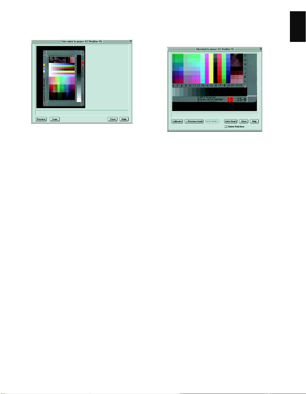
B. The Calibration Window: Preview and Scan
1. Preview: The Preview button performs a preliminary
scan of the target, displaying the entire target image in
the calibration window .
2. Scan: The Scan button scans the target image and
prepares the scanner for the important succeeding
steps of aligning the registration marks and creation of
the profile.
C. The Calibration Window: Aligning targets and
creating the profile
1. Calibrate: This button starts the actual calibration
process in which a custom scanner ICC profile is
created for the scanner. This b utton is grayed out until
you have performed the required alignment of the three
registration marks on the target.
2. Previous Mark: This button lets you go back one step
to align the previous registration mark.
3. Next Mark: This button lets you go forward one step
to align the next registration mark.
4. Go to Step 1: This button takes you back to the
preview image screen so that you can rescan the target
image and restart the calibration process.
5. Show Patches: This option lets you check the
sampling area of all the color patches. When aligned
properly, the sampling area appears as a green square
in the center of most patches. If any areas fall outside a
patch, realign the registration marks by clicking the
“Previous Mark” and “Next Mark” buttons, and then
reselecting the registration marks until the sampling
areas are centered.
6. Close: This button lets you return to the main screen.
English
ArtixScan 1100 Hardware User’s Guide 35
 Loading...