

Page 1

Page 2

i
Copyright © 2005 Microtek International,Inc.
Microtek® is a registered trademark of Microtek International, Inc. All other
trademarks or registered trademarks are the property of their respective holders.
Specifications, software and hardware bundles are subject to change without notice.
Delivery of technical support services subject to change without notice. Not
responsible for typographical errors.
A new FCC Compliance Statement
This device complies with part 15 of the FCC Rules. Operation is subject to the
following two conditions:
1. This device may not cause harmful interference, and
2. This device must accept any interference received, including interference that
may cause undesired operation.
FCC Warning
This equipment has been tested and found to comply with the limits for a Class B
digital device, pursuant to Part 15 of the FCC Rules. These limits are designed to
provide reasonable protection against harmful interference in a residential
installation.
This equipment generates, uses and can radiate radio frequency energy and, if not
installed and used in accordance with the instructions, may cause harmful
interference to radio communications.
However, there is no guarantee that interference will not occur in a particular
installation. If this equipment does cause harmful interference to radio or television
reception, which can be determined by turning the equipment off and on, the user is
encouraged to try to correct the interference by one or more of the following
measures:
• Reorient or relocate the receiving antenna.
• Increase the separation between the equipment and the receiver.
• Connect the equipment into an outlet different from that to which the receiver is
connected.
• Consult the dealer or an experienced radio/TV technician for help.
Caution:
To comply with the limits for an FCC Class B computing device, always use the
shielded signal cord supplied with this unit.
The Federal Communications Commission warns that changes or modifications of
the unit not expressly approved by the party responsible for compliance could void
the user’s authority to operate the equipment.
Page 3

ii
CE mark for Class B ITE (Following European standard EN55022/
1998; EN61000-3-2/1995; EN61000-3-3/1995, EN55024/1998,
EN60950/1992+A1+A2+A3+A4+A11)
Radio Frequency Interference Statement
Warning:
This is a Class B product. In a domestic environment, this product may cause radio
interference in which case the user may be required to take adequate measures.
Canadian Doc Notice
For Class B Computing Devices
This digital apparatus does not exceed the Class B limits for radio noise emissions
219-20-990426 A
Page 4

iii
Table of Contents
Introduction .................................................................................. 1
Product Features..................................................................... 1
Unpacking ............................................................................... 2
Precautions ............................................................................. 2
Cleaning .................................................................................. 3
Installation .................................................................................... 4
Installing the Base Pedestal................................................... 4
VESA Mount Setup................................................................. 5
Connecting the Monitor ............................................................... 6
Adjusting the Viewing Angle........................................................ 7
Operating the Monitor .................................................................. 8
A. The LCD Monitor’s Control Panel...................................... 8
B. Adjusting the Monitor’s Display ....................................... 9
The Menu Table .....................................................................10
TFT LCD Monitor Specifications ................................................. 11
Supported Timing ...................................................................... 12
Troubleshooting.......................................................................... 13
Page 5

1
Introduction
Congratulations on the purchase of your new Microtek LCD
monitor! With a 17" TFT active matrix color crystal display and
offering a maximum resolution of 1280 x 1024 pixels, your LCD
monitor offers sharp and vibrant color display with low
radiation emission. And with its low power consumption, the
monitor helps you reduce your power bill as well.
Product Features
• 17” TFT color Liquid Crystal Display
• Supports SXGA resolution of 1280 x 1024 pixels
• VESA PMS-compliant power saving: Automatically powers
down the monitor after a defined period of inactivity
• Compatible with Windows 95/98/2000/XP and Macintosh
• Easy-to-use OSD (On-Screen Display)
• Plug & Play: Conforms to IBM VGA, VESA standards and
supports DDC1/2B specifications
• Multiscan functions of SXGA 1280 x 1024, XGA 1024 x 768,
SVGA 832 x 624, 800 x 600, VGA 640 x 480, 720 x 400, and 720
x 350 for perfect graphics performance
• Extra-slim design to maximize your desk space
• Includes built-in speakers
Page 6

2
Unpacking
Before unpacking your LCD monitor, prepare a stable, level, and
clean surface near a wall outlet for your LCD monitor.
1. Set the LCD monitor box in an upright position and open
from the top of the box before removing the right/left
cushions.
2. Check to see that you have the following accessories shown
below:
• LCD monitor
• Power cord
• 15-pin D-sub signal cable
• Audio cable
• User Guide
Note: Remember to save your original box and packaging
material in case you need to transport or ship the monitor. If
you have to return your unit for service and the original
packaging has been discarded, please contact your dealer or
nearest service center for advice or replacement of packaging.
Precautions
• Read all of these warnings and save the manual for later use.
• Follow all warnings and instructions on the product.
• Do not cover or block the vent holes in the case.
• Do not insert sharp objects or spill liquid into the LCD
monitor through the cabinet slots; this may cause accidental
fire, electric shock or failure.
• Disconnect the power plug from the AC outlet if you are not
going to use the monitor for an extended period of time.
• Do not attempt to service this product yourself, as opening or
removing the cover may expose you to dangerous voltage
points or other risks.
• Do not touch the screen directly with your fingers as you may
damage the screen, and oil from your skin is difficult to
remove.
Page 7

3
• Do not apply pressure to the screen, as the screen is very
delicate.
• Keep the monitor away from extremely hot, cold or humid
places.
• Do not place the monitor directly under sunlight, in dusty
surroundings, or near equipment which may generate strong
magnetic fields.
Cleaning
Warning:
If you drop any material or liquid such as water onto the
monitor when cleaning, unplug the power cable immediately
and contact your dealer or the nearest service center. Always
make sure your hands are dry when unplugging the power
cable.
Caution:
• For safety reasons, turn off the power switch and unplug the
monitor before cleaning.
• Do not scratch or rub the screen with a hard object.
• Never use any of the following solvents on the LCD monitor:
Thinner; spray-type cleaners; benzene; wax; abrasive
cleaners; and acid or alkaline solvents. Such harsh chemicals
may cause damage to the cabinet and the LCD screen.
• Rubbing the cabinet with products made of rubber or plastic
for prolonged periods may cause degeneration or loss of
paint on the cabinet.
Cabinet
• Remove dirt with a lightly moistened cloth and a mild solvent
detergent. Then wipe the cabinet with a soft dry cloth.
LCD
• Periodic cleaning with a soft dry cloth is recommended.
• Do not use tissue to clean the LCD screen, as this may
damage the screen.
Page 8
4
Installation
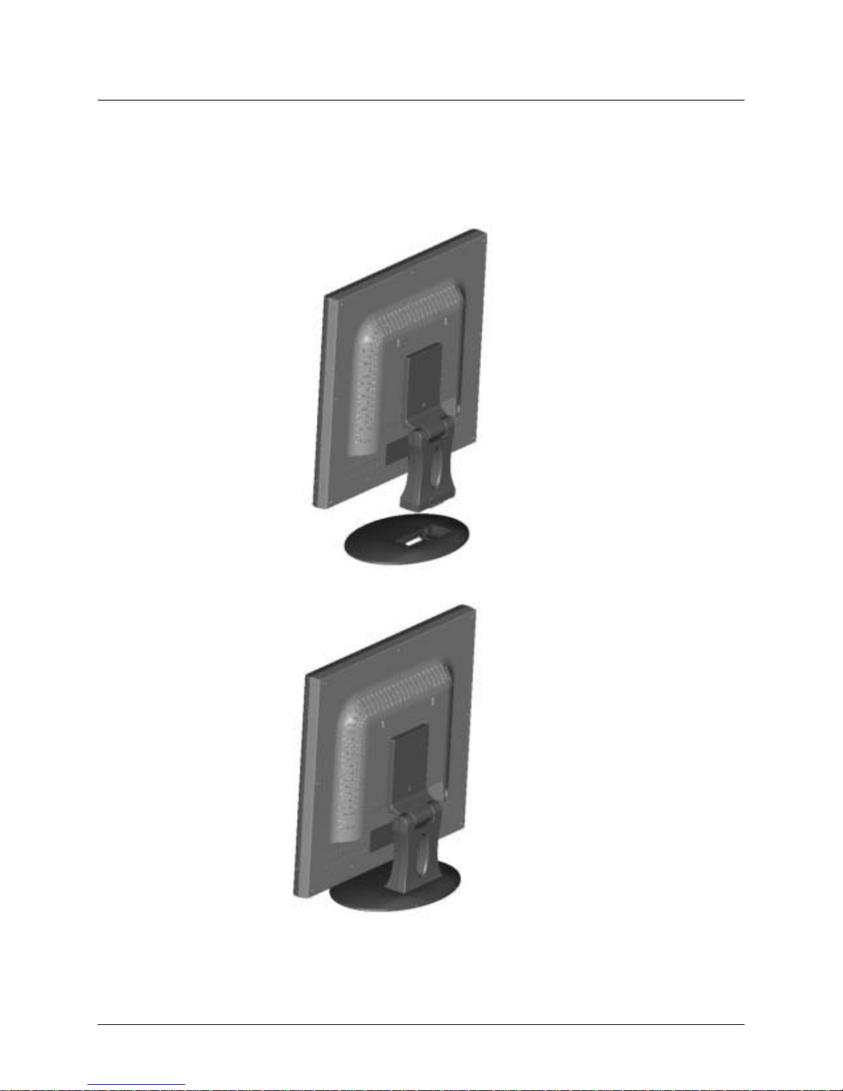
Installing the Base Pedestal
STEP 1
STEP 2
Page 9

5
1. Disconnect all cables.
2. Place the monitor face down on a non-abrasive surface.
3. Remove the screw (A) and lift off VESA cover. (STEP 1)
4. Remove the 4 screws (B.C.D.E), connect the monitor to the
stand, and lift off the stand assembly. The monitor is now
ready for mounting in an alternate manner. (STEP 2)
Note:
• To meet safety requirements, the monitor must be mounted to
an arm that guarantees the monitor's stability.
• The LCD monitor should only be used with an approved arm.
VESA Mount Setup
B
C
D
E
STEP 2
STEP 1
Page 10
6
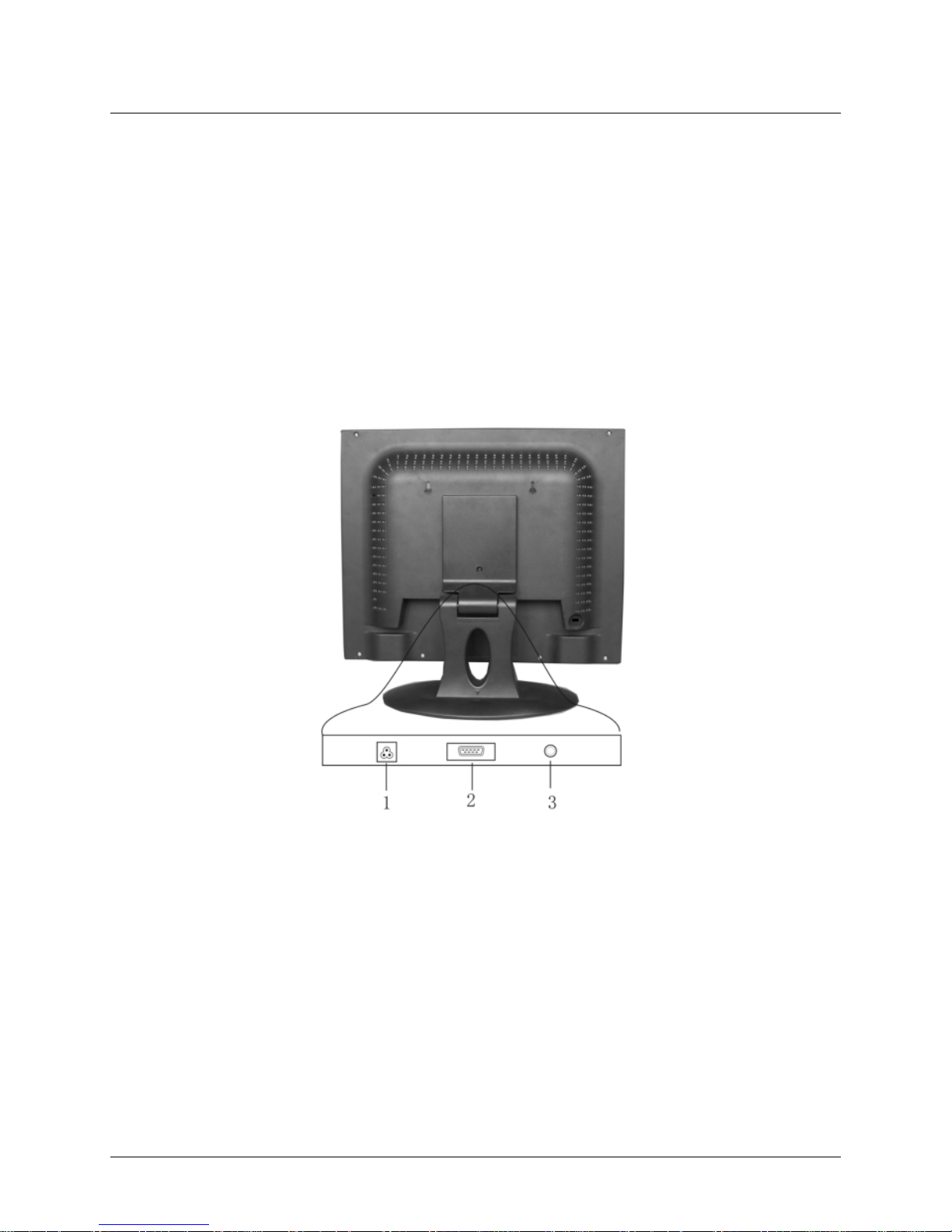
Connecting the Monitor
• Turn off your PC and the LCD monitor before connecting your
LCD monitor to the computer.
• Place the monitor on a flat and level surface.
• Usage of incorrect voltage will cause malfunction and may
cause fire or electric shock.
• Do not pull or bend the power cable or place the monitor or
any heavy objects on the cables. If the cables are damaged,
they may cause fire or electric shock.
1. AC Power: Plugs into the AC power adapter.
2. PC IN: Connects with the 15-pin D-Sub signal cable.
3. Audio jack: Connects with the Audio cable.
Figure-1: The LCD Monitor Rear View
Page 11
7
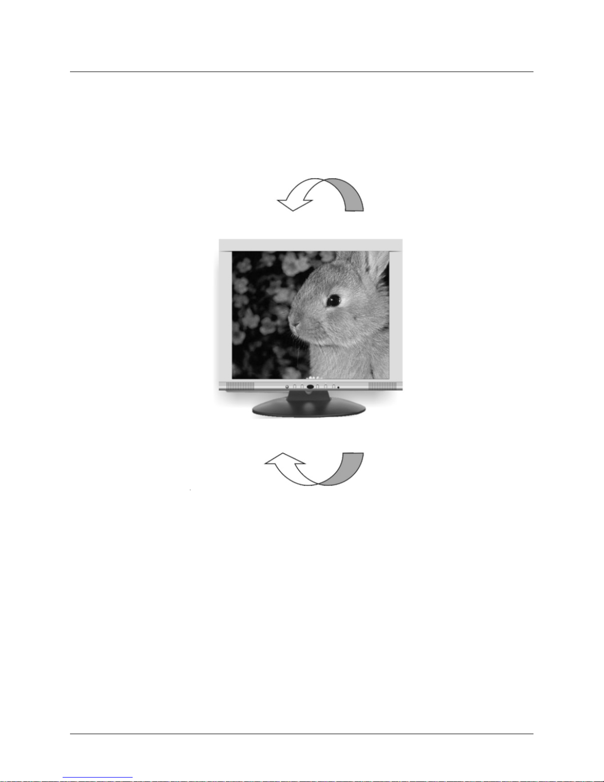
Adjusting the Viewing Angle
For optimal viewing, the viewing angle of the monitor can be
adjusted 35 degrees up and 5 degrees down.
Figure-2: Tilting the LCD Monitor
Down: 3°
Up: 35°
Page 12

8
Operating the Monitor
A. The LCD Monitor’s Control Panel
Figure-3: The Control Panel
1. Auto: Automatically fixes, centers and fine-tunes the video
signal to eliminate noise and distortion.
2. OSD Menu/select: Displays the OSD menu and selects a
submenu item.
3. Adjustment button —: Indicates cursor movement, or
decreases the value of a selected OSD setting.
4. Adjustment button +: Indicates cursor movement, or
increases the value of a selected OSD setting.
5.
Power switch: Turns power for the LCD monitor ON
or OFF.
6. Power LED: Indicates various status levels for the monitor,
such as Green (Normal operation) or Orange (Power
management), depending on the monitor’s operating mode.
Page 13

9
B. Adjusting the Monitor’s Display
1. Pressing the OSD Menu button causes the screen below
(Figure 4) to appear.
2. Press the + or — button to select a menu item.
3. Press the OSD Menu button again to enter the selected
submenu.
4. Press the + or — button to change values.
5. Select EXIT and press the OSD Menu button when finished
adjusting.
Figure-4: The OSD Main Menu
Page 14

10
The Menu Table
Main Menu Submenu Function
BRIGHTNESS Adjusts the level of brightness and darkness.
CONTRAST Adjusts the RGB color pattern set of the contrast.
V-POSITION Moves the screen vertically (up/down).
H-POSITION Moves the screen horizontally (left/right).
PITCH Adjusts image distortion appearing as vertical bars or
noise.
DISPLAY ADJUST PHASE Adjusts image distortion appearing as horizontal bars or
noise.
SHARPNESS Adjusts the LCD monitor display to sharpen the image.
AUTO TUNING Automatically fixes, centers and fine-tunes the video signal
to eleminate noise and distortion.
RECALL Resets all of the DISPLAY ADJUST settings to their default
values.
RETURN Returns to the previous menu.
COLOR TEMPERATURE Adjusts the colors in the LCD monitor to a warmer or
cooler shade, depending on the selected color
temperature.
LANGUAGE Changes the OSD language, including English, Spanish,
German, Italian, French, and Chinese.
OSD V-POSITION Moves the OSD menu vertically (up/down).
OSD H-POSITION Moves the OSD menu horizontally (left/right).
OSD TIMER Sets the length of time an OSD screen is displayed.
OSD ADJUST OSD TRANSPARENCY Adjusts the transparency of the OSD screen.
RECALL Resets all of the OSD ADJUST settings to their default
values.
RETURN Returns to the previous menu.
MUTE Turns the audio on or off.
AUDIO CONTROL VOLUME Adjusts the volume.
RECALL Resets all of the AUDIO CONTROL settings to their default
values.
RETURN Returns to the previous menu.
RESET Resets all of the monitor’s settings to their default values.
EXIT Exits the OSD screen.
Page 15

11
TFT LCD Monitor Specifications
LCD Type 17” SXGA Color TFT
Display Area 13.3” x 10.6” (337.9 x 270.3 mm)
Input Signal Analog (0.7 Vp-p/75 ohm positive)
Dot Pitch 0.264 mm
Scanning Frequency (H) 31.469 ~ 80.000 KHz
(V) 56.250 ~ 75.029 Hz
Resolution 1280 x 1024 pixels
Display Color 16 million colors
Contrast Ratio 500:1 (Typical)
Brightness 300 nit
Response Time 12 ms (Typical)
Viewing Angle (H) 160°/(V) 160°
Plug and Play VESA DDC 1/2B
Audio 2W*2
Dimensions (H x W x D) 16.3” x 18.5" x 6.3"
(415 x 470 x 160 mm)
Gross/Net Weight 10.6/8.3 lbs. (4.83/3.76 Kg)
Tilt +35°/-3°
Swivel No
Height Adjustment No
Wall Mount Yes (75 x 75 mm)
AC Input AC 100 V ~ 240 V, 50/60 Hz
Power Management VESA DPMS
Power Consumption 35 W Max (on)/5 W
(Power Saving off mode)
Regulatory Compliance FCC Class B, UL, Energy Star
Important: Specifications, bundles, and accessories are
subject to change without notice.
Page 16

12
Supported Timing
metInoituloseR
gninnacSlatnoziroH
)zHK(ycneuqerF
gninnacSlacitreV
)zH(ycneuqerF
0053x027964.13780.07
1053x027964.13780.07
2084x046964.13049.95
3084x046000.53766.66
4084x046168.73908.27
5084x046005.73000.57
6004x027964.13780.07
7006x008651.53052.65
8006x008978.73713.06
9006x008770.84881.27
01006x008578.64000.57
11426x238057.94005.47
21867x4201363.84400.06
31867x4201674.65960.07
41867x4201830.85819.17
51867x4201320.06920.57
614201x0821000.46000.06
714201x0821000.08000.57
Page 17

13
Troubleshooting
This LCD monitor comes pre-adjusted with standard VGA
timing. Due to output timing differences among various VGA
cards, you may initially experience an unstable or unclear
display when a new display mode or new VGA card is selected.
Before applying any of the following troubleshooting
procedures, you should first apply the Auto Adjust option in the
OSD menu.
PROBLEM: Display is unclear and unstable
To stabilize and clarify your display, press the OSD menu
button, and adjust the clock and phase to obtain a clear display.
PROBLEM: There is no LCD display
If there is no display on the LCD, refer to the following:
1. Make sure that the power indicator on the LCD monitor is lit,
that all connections are secure, and that the system is
running on the correct timing. Refer to “Supported Timing”
on page 12.
2. Turn off the LCD monitor and then turn it back on again.
Press the OSD Menu button once and then press one of the
Adjustment Control buttons several times. If there is still no
display, press the other Adjustment Control button several
times.
3. If step 2 does not work, connect your PC system to another
external CRT. If your PC system functions properly with a
CRT monitor but it does not function with the LCD monitor,
and the LCD monitor’s power LED is blinking, the output
timing of the PC’s VGA card may be out of the LCD’s
synchronous range. Change to one of the alternate modes
listed in the “Supported Timing” section on page 12, or
replace the VGA card and repeat steps 1 and 2.
4. If the power LED is not lit, check that the AC power connector
is securely connected, and verify that the AC adapter LED is
lit. If the AC adapter LED is not lit, please contact your
dealer for assistance.
 Loading...