

Page 1

710S 17” LCD MONITOR
USER’S MANUAL
Page 2

ii
Table of Contents
FCC Compliance Statement .................................................................... ii
Introduction ..............................................................................................1
Factory-preset Modes .............................................................................2
Specifications .......................................................................................... 3
Installing the Monitor ...............................................................................5
Control Functions .....................................................................................7
Appendix ............................................................................................... 14
Signal connector pin assignment ......................................................... 16
Page 3

iii
FCC Compliance Statement
This device complies with part 15 of the FCC Rules. Operation is subject to the
following two conditions:
1. This device may not cause harmful interference, and
2. This device must accept any interference received, including interference
that may cause undesired operation.
FCC Warning
This equipment has been tested and found to comply with the limits for a Class B
digital device, pursuant to Part 15 of the FCC Rules. These limits are designed to
provide reasonable protection against harmful interference in a residential
installation.
This equipment generates, uses and can radiate radio frequency energy and, if not
installed and used in accordance with the instructions, may cause harmful
interference to radio communications.
However, there is no guarantee that interference will not occur in a particular
installation. If this equipment does cause harmful interference to radio or television
reception, which can be determined by turning the equipment off and on, the user is
encouraged to try to correct the interference by one or more of the following
measures:
• Reorient or relocate the receiving antenna.
• Increase the separation between the equipment and the receiver.
• Connect the equipment into an outlet different from that to which the
receiver is connected.
• Consult the dealer or an experienced radio/TV technician for help.
Caution:
To comply with the limits for an FCC Class B computing device, always use the
shielded signal cord supplied with this unit.
The Federal Communications Commission warns that changes or modifications of
the unit not expressly approved by the party responsible for compliance could void
the user’s authority to operate the equipment.
CE mark for Class B ITE (Following European standard EN55022/1998; EN61000-3-2/
1995; EN61000-3-3/1995, EN55024/1998, EN60950/1992+A1+A2+A3+A4+A11)
Page 4

iv
Radio Frequency Interference Statement
Warning:
This is a Class B product. In a domestic environment, this product may cause radio
interference in which case the user may be required to take adequate measures.
Canadian Doc Notice
For Class B Computing Devices
This digital apparatus does not exceed the Class B limits for radio noise emissions
from digital apparatus as set out in the Radio Interference Regulation of the
Canadian Department of Communications.
“Le présent appareil numérique n’èmet pas de bruits radioélectriques dépassant les
limites applicables aux appareils numériques de la class B prescrites dans le
Règlement sur le brouillage radioélectrique édicté par le ministère des
Communications du Canada”
Page 5

v
8. Use the monitor only with the supplied adapter. In case of loss, contact the
retailer or service center.
9. If you lose the power cord, you must purchase a power cord of the same
type and configuration.
• Japan GVCTF type, 3 wires or with ground-wire; T-mark approval is
required.
• U.S. GVW-1; 18AWG X 3C; SVT with national approval as UL and/or CSA
approval/number(s)
• Europe GVDE/ÖVE and/or KEMA approval; H05VV-F, 3G, 0.75mm2, or
equivalent.
The power cord should bear the name of the manufacturer and state the
type of cord that it is.
Important Safety Instructions
Please read the following instructions carefully. This manual should be retained for
future use.
1. To clean the LCD monitor screen, make sure the monitor is in the power off
mode. Unplug the monitor from its power source before cleaning it. Do not
spray liquid cleaners directly onto the unit. Stand away from the LCD
monitor and spray cleaning solution onto a rag. Without applying excessive
pressure, clean the screen with the slightly dampened rag.
2. Do not place your LCD monitor near a window. Exposing the monitor to
rain, water, moisture or sunlight can severely damage it.
3. Do not place anything on top of the monitor-to-PC signal cord. Make sure
the cord is placed in an area where it will not be stepped on.
4. Do not apply pressure to the LCD screen. Excessive pressure may cause
permanent damage to the display.
5. Do not remove the cover or attempt to service this unit by yourself,as you
may void the warranty. Servicing of any nature should be performed only
by an authorized technician.
6. Safe storage of the LCD monitor is in the range of -4°F to 140°F (–20°C to
+60°C). Storing your LCD monitor outside this range could result in
permanent damage.
7. If any of the following occurs, immediately unplug your monitor and call an
authorized technician.
• The power or monitor-to-PC signal cord is frayed or damaged.
• Liquid has been spilled onto the monitor, or it has been exposed to rain.
• The monitor has been dropped or the case has been damaged.
Page 6

1
Introduction
Before installing your monitor
Read this manual carefully .
P AY ATTENTION to all Warning and Caution messages.
DO NOT use computer components not recommended by the
manufacturer.
Do not attempt to service the monitor yourself. If a problem occurs,
contact the manufacturer’s authorized service center .
About your monitor
This monitor is a microprocessor-controlled color monitor that uses a TFT
LCD panel. The monitor conforms to EP A Energy Star and VESA DPMS
(Display Power Management Signaling) power management standards.
RGB Mode
This monitor is equipped with a microprocessor that identifies your
computer’s video mode and allows you to adjust the setting.
Page 7
2
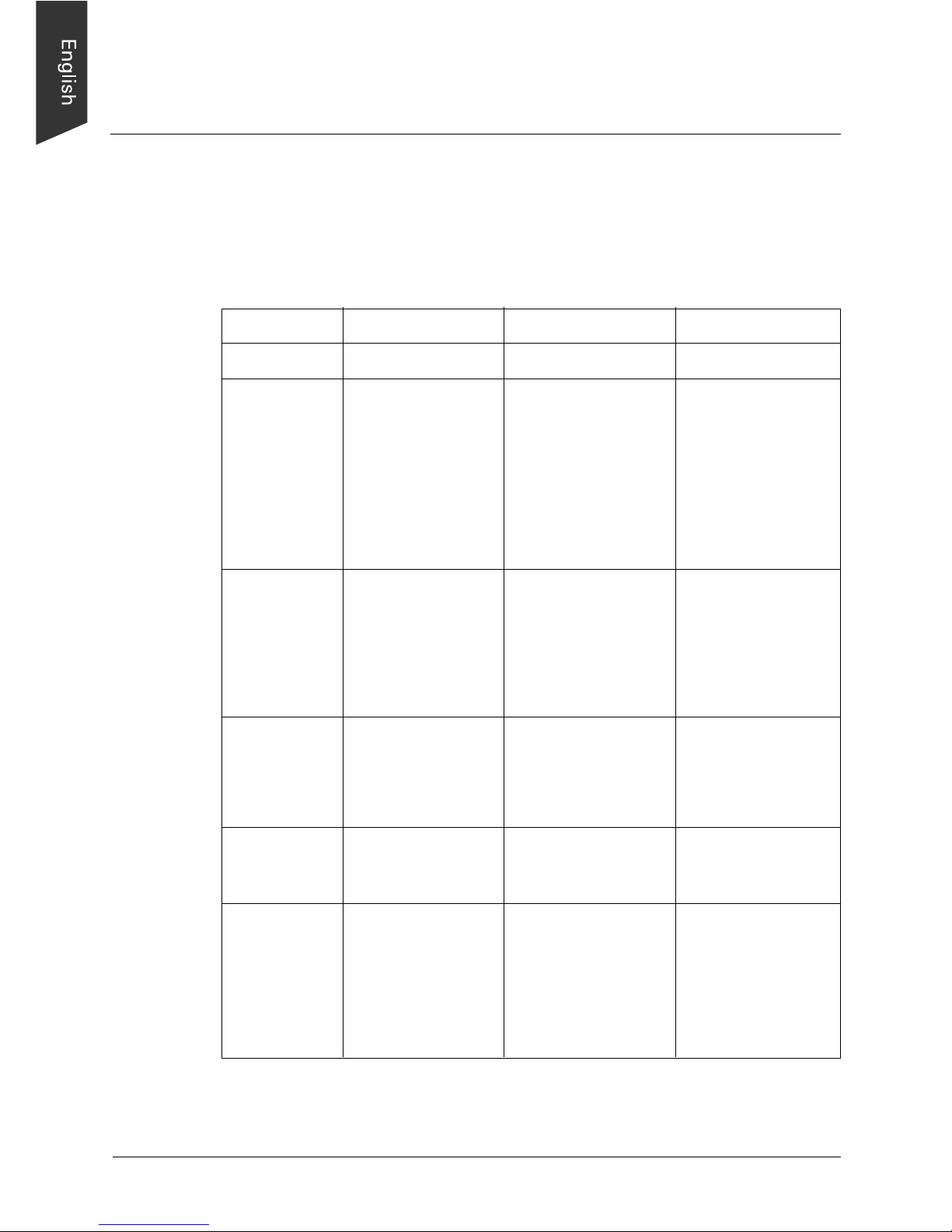
Factory-preset Modes
Table 1 shows standard video mode setting that has been pre-adjusted at
the factory for accurate video display. These settings are stored in the
monitor’s memory .
Table 1. Factory-preset Modes
Mode
NEC
VGA
SVGA
XGA
SXGA
Macintosh
Resolution
640 x 400
640 x 350
720 x 400
640 x 480
640 x 480
640 x 480
800 x 600
800 x 600
800 x 600
800 x 600
1024 x 768
1024 x 768
1024 x 768
1280 x 1024
1280 x 1024
640 x 480
832 x 624
1024 x 768
1024 x 768
H-Freq. (KHz)
24.83
31.47
31.47
31.47
37.86
37.5
35.16
37.88
48.08
46.87
48.36
56.47
60
63.98
80
35
49.7
48.78
60.241
V-Freq (Hz)
56.4
70
70
60
72
75
56.3
60.3
72.2
75
60
70
75
60
75
66.7
74.55
60
74.927
Page 8

3
Specifications
Overall Dimensions (H x W x D): 16.5 x 16.4 x 6.5 in.
(419 x 417 x 166 mm)
Gross / Net Weight 14.4 / 12 lbs
Effective Display area (H/V): 13.3 x 10.6in.
(337.92 x 270.34 mm)
Wall Mount 100 x 100mm (VESA standard)
Display colors: 16 million colors
Scan Frequencies:
Horizontal 31.47K to 80KHz
V ertical 60Hz to 75Hz
Number of Pixels: 1280x1024 pixels
Pixel pitch: 0. 264 mm
Picture Tube: 17" TFT LCD panel
Power:
Input 110~240 V AC (auto-sensing)
Frequency: 48-62Hz
Consumption 45Watts maximum (on)
1 W att (Power saving of f mode)
V ideo Connector 15-pin Mini D-sub (Standard)
Audio connector 1 (stereo input)
Speaker: 2
RGB Signals:
V ideo Analog RGB 0.7Vp-p/75W
Sync Separate
Display Data Channel:
Compatibility VESA DDC 1/2B
Page 9

4
Operations
User Controls On/Off Power Button
Auto-adjustment, Brightness,
Menu/Enter and & button
On Screen Display , Contrast,
Brightness Adjustment,
H-position, V-position,
Color temperature,
Auto Adjustment
Control T ype: Digital OSD (On-Screen-Display)
Compatibility: IBM and compatibles, Apple
Macintosh, NEC
Environmental Limits:
Operating T emp. 32° to 104°F ( 0° to 40°C)
Storage T emp. -4° to 140°F (-20° to 60°C)
Operating Humidity 10 to 85% without Condensation
Storage Humidity 10 to 95% without Condensation
Agency Approval
EMI FCC, CE
Energy Saving EP A ener gy star, VESA DPMS
Safety UL/CUL, CB, TUV , BSMI
Page 10
5
Installing the Monitor
This monitor is equipped with an auto sensing power supply for voltage
ranging from 110~240VAC, 60/50Hz. Confirm the line voltage designation
on the rear panel of the monitor .
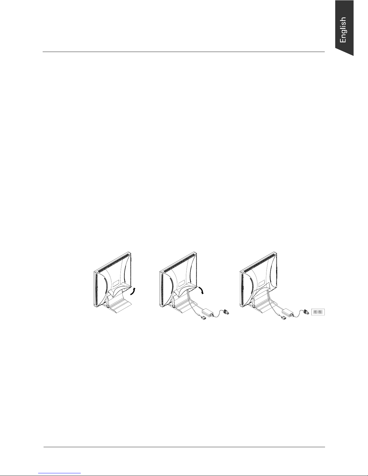
To install the monitor, follow these steps:
1. Before you connect the cables, make sure that the monitor and the
system unit power switches are OFF.
2. Plug one end of the 15-pin signal cable to the monitor and the other
end to the video signal connector at the rear of the system. Tighten
the two screws on the cable connector on both ends. Otherwise, the
screen will be abnormal and the LED light will flash yellow (and not
the normal green color).
3. Connect the power to the monitor through the AC/DC adapter .
4. Connect the power cord on the AC outlet as shown below.
12 3
Page 11

6
How to use the VESA mount
1. Locate the slider on the back side of the stand.
2. Push the slider to the right.
3. While pressing on the slider with one hand, use the other hand to
bring the LCD panel down until it is on an even level with the VESA
mount. Locate the holes for mounting and affix the monitor as desired.
Page 12
7
Control Functions
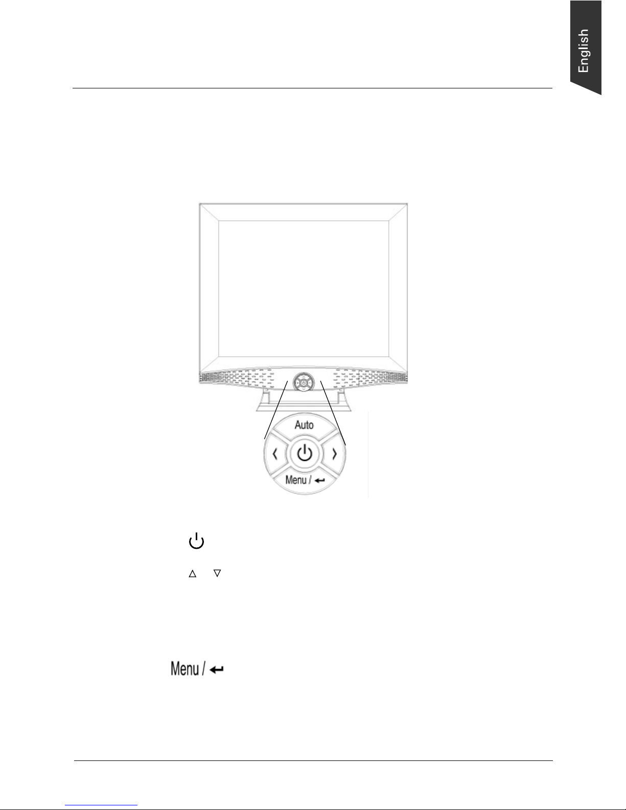
The control functions of the monitor are located on a dial in the lower
center portion of the front panel. They are shown in the figure below and
described in the following paragraphs.
17” LCD Monitor
Description of control keys:
1. : Power Switch
2. & : Cursor up/down or
Decrement /Incremental; or
Brightness Up/Down (hot key)
3. : Menu/ Enter
4. Auto : Auto adjustment (hot key)
Note: A hot key indicates that a particular function will work without
the need to activate the On-screen display (OSD) menu.
Page 13

8
1. : Power switch
Use the power switch to turn power ON or OFF . We recommend
turning your system power on first before turning on the monitor.
2. & : Up and Down
These two keys are used to move the cursor up or down. These two
keys are also used to increase or decrease values for items selected
through the key.
3. Auto: Auto-adjustment
This is a hot key that automatically adjusts the phase and position of
the LCD monitor for the best view setting.
4. :key
Press the Menu key to activate the OSD (on-screen display). When
the OSD screen is in use, this key functions as the Enter key . After 10
seconds of idle time, however, the OSD screen automatically turns off .
Page 14

9
Adjusting the monitor
The LCD monitor is designed to work with a range of compatible video
adapters on the market. Due to the possible deviations between these
video adapters, you may need to make some adjustments to fit the monitor
for the adapter being used.
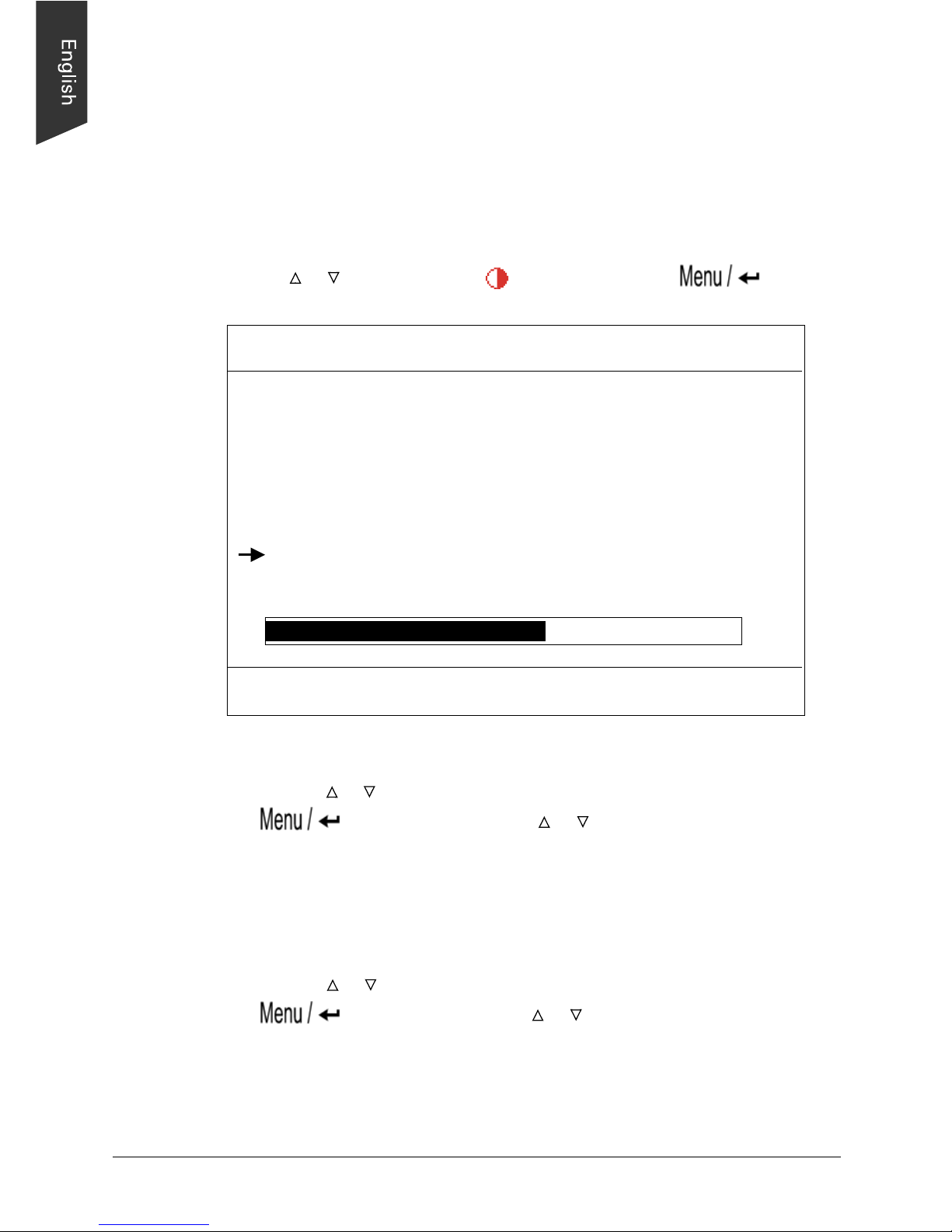
Adjustment Procedure
1. Activate the OSD screen by pressing any OSD key . A screen similar to
the one below will appear; the highlight bar will depend on the OSD
key you are using. If you press the & keys, the bar will be at the
volume item.
OSD SCREEN
2. Use the & key to move to the item to be adjusted, then press the
key to select the item for adjustment.
3. Use the & key to change the value of the item to be adjusted.
MENU
MENU
MENU
1280X1024 75 Hz/80 KHz
AUTO ADJUSTMENT
LANGUAGE
DOS TXT/GFX OFF
USER
50
OFF
100
VERSION SXGAHF581-4500
Page 15
10
Auto
We strongly recommend that you use the Auto hot key to get optimized
visual quality from your monitor . Pressing the Auto key will perform the
adjustment automatically .
RGB Adjustment
Use the & key to select the icon, then the press key. A
screen similar to the one below will appear.
• Contrast Adjustment
Use the & key to select the CONTRAST item, then press the
key to highlight. Press & to get the best contrast
optimization. With this control, you can adjust the Red, Green, and
Blue (R,G,B) channels simultaneously or individually . Y ou can also use
this control to change RGB purity .
• Color Balance Adjustment
Use the & key to select the color balance item, then press the
key to highlight. Press & to get the best color balance
effect or to set the RGB color values individually . You can also use
this control to change RGB intensity .
Note: The easiest way to adjust the contrast and color balance setting is
to use the auto-balance item.
1280X1024 75 Hz/80 KHz
Auto-Balance
CONTRAST
RED 20
GREEN 18
BLUE 19
BALANCE
RED 49
GREEN 50
BLUE 26
EXIT
VERSION SXGAHF581-4500
Page 16

11
Geometry adjustment
Use the & key to select the icon, then press the key . A
screen similar as below will appear .
T o go back to the previous OSD menu screen, move to the exit item, then
press the key.
VERTICAL & HORIZONTAL POSITION ADJUSTMENT
Use the & key to move to the icon for vertical adjustment or to the
icon for horizontal adjustment, then press the key to
highlight, press & to move the entire screen left or right relative to the
center position.
1280X1024 75 Hz/80 KHz
223
24
1056
PHASE 25
EXIT
VERSION SXGAHF581-4500
Page 17

12
Screen size adjustment
Use the & key to move to the icon , then press key to
highlight. Press & to get a larger or smaller viewing size.
PHASE adjustment
Adjust the phase tracking of the display signal to reduce display flicker.
An invalid phase tracking will cause unstable and flickering display .
Use the & key to move to the Phase item, then press the
key to highlight. Press & to obtain better image quality .
Languages
Five OSD languages are supported for this monitor, as shown by the
screen below .
1280X1024 75 Hz/80 KHz
English
German
French
Italian
Spanish
VERSION SXGAHF581-4500
Page 18

13
DOS Txt/GFX
This allows you to select the display mode as 640x400 (graphic mode), or
as 720x400 (text mode).
Color Temperature
Three modes are provided: user mode, 6500, and 9300. Move the cursor
key to the color temperature item through the & key, then press the
to switch among settings. Take note that when the temperature
is set at 6500 or 9300, you will not be able to change the value.
Brightness Adjustment
Use the & key to select the item, then press the key to
highlight. Press & to change the volume value.
Audio Volume Control
Use the & key to select the item, then press the key to
highlight. Press & to change the volume value.
Mute On/Off
Use the & key to select the item, then press the key to
highlight. Press & to turn on or off the audio mute function.
Understanding the display resolution setting
In the OSD screen, you will see the Horizontal frequency (HF), V ertical
frequency (VF), display resolution (MODE) and the monitor Firmware
version (ROM VERSION). These settings are automatically detected by
the monitor, and you will not be able to change them.
Page 19

14
Appendix
Troubleshooting Procedures
This LCD Monitor was pre-adjusted in the factory with standard VGA
timing. Due to output timing differences among various VGA cards, you
may initially experience an unstable or unclear display when a new display
mode or new VGA card is selected.
Note : This LCD Monitor Supports Multiple VGA Modes. Refer to the
timing table for a listing of factory-preset modes supported by this LCD
Monitor.
Problem: There is no LCD Display
If there is no display on the LCD, please perform the following steps:
1 . Make sure that the power indicator on the LCD Monitor is lit, all
connections are secure, and the system is running on the correct
timing. Refer to table 1 on page 6 for information on timing.
2. Turn of f the LCD monitor , then turn it back on. Press the upper
Function Control button once and then press either the upper or lower
Adjustment Control button several times. If there is still no display ,
press the other Adjustment Control button several times.
3. If step 2 does not work, connect your PC system to another external
CR T . If your PC System functions properly with a CR T Monitor but it
does not function with the LCD monitor, and the LCD monitor’s power
LED is blinking, the output timing of the PC’s VGA card may be out of
the LCD’s synchronous range. Please change to an alternate mode
listed in table 1 on page 6, or replace the VGA card and repeat steps 1
and 2.
Page 20

15
4 . If the PC does not function with the CRT monitor, check the BIOS to
see if there is a dual scan setting under the display mode item. Set the
BIOS display mode to Dual Scan or CRT and try again. If there is still
no display, then there may be a problem with your system. Contact
technical support.
5 . If the power LED is not lit, check to see if the AC power connector is
securely connected. Verify that the AC adapter LED is lit. If the AC
adapter LED is not lit, please contact your dealer for assistance.
Page 21
16
Signal connector pin assignment
Power connector
Pin 1
Pin 2
Ground
+12V output
Analog Red Input
Analog Green Input
Analog Blue Input
Ground
Digital Ground
Analog Red Input
Analog Green Input
Analog Blue Input
NC
Sync Ground
Ground
SDA (DDC Data)
H.Sync
V.Sync
SCL (DDC CLK)
Pin 1
Pin 2
Pin 3
Pin 4
Pin 5
Pin 6
Pin 7
Pin 8
Pin 9
Pin 10
Pin 11
Pin 12
Pin 13
Pin 14
Pin 15
RGB signal connector
 Loading...