

Page 1
M
ICRONIX
P
OWER
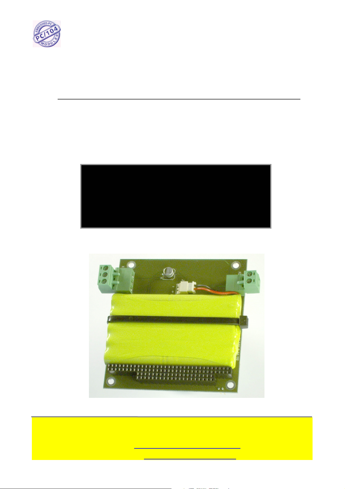
PV-1075 & PV-1075-CAR
NiMH battery pack with charger
for PV-5127
PC/104
S
UPPLY
User Manual
&
Installation Guide
V
ERS.
1.3
DOC: M5247DM.REV1.3
Micro Technic A-S • Denmark •
Tel. +45 6615 3000 • Fax +45 6615 3077
E-mail: support@micro-technic.com
Website: www.micro-technic.com
Page 2

Users Manual & Installation Guide
PV- 1075: NIMH
BATTERY PACK WITH CHARGER
Table of contents
TABLE OF CONTENTS ................................................................................................................................................. 2
GENERAL INFORMATION .......................................................................................................................................... 4
O
RDERING CODES
A
CCESSORIES
DESCRIPTION ................................................................................................................................................................ 5
B
LOCK DIAGRAM
CONNECTORS ................................................................................................................................................................ 6
I
NPUT CONNECTOR
O
UTPUT CONNECTOR
B
ATTERY CONNECTOR
PC/104
BATTERY CHARGER.................................................................................................................................................... 7
C
CONNECTOR
HARGING INDICATORS
........................................................................................................................................................... 4
.................................................................................................................................................................. 4
........................................................................................................................................................... 5
(KL2)............................................................................................................................................... 6
(KL1) ........................................................................................................................................... 6
(J1).............................................................................................................................................7
(CN1) ............................................................................................................................................ 7
.................................................................................................................................................. 7
TECHNICAL DATA........................................................................................................................................................ 8
MECHANICAL LAYOUT ............................................................................................................................................. 9
Page 2 of 9
Page 3

Users Manual & Installation Guide
PV- 1075: NIMH
BATTERY PACK WITH CHARGER
Revision history
Revision number Reason for change Date
1.0 Initial revision 05-Apr-04
1.1 Added PV-1075-car version 06-Dec-05
1.2 Changed front page 07-Apr-18
1.3 Changed “discharge current” 07-Dec-03
Page 3 of 9
Page 4

Users Manual & Installation Guide
PV- 1075: NIMH
BATTERY PACK WITH CHARGER
General information
Ordering codes
PV-1075-S
S=Stack-through PC/104 connector
Available models:
Model Ordering
code
PV-1075-S 016.104.005 NiMH battery pack with charger.
PV-1075-S-CAR 016.104.093 NiMH battery pack with charger for mobile applications.
Accessories
This accessories must be ordered separately if needed.
Model no Ordering code Description
PV-1075-NH12 155.104.000 Battery pack
Description
Page 4 of 9
Page 5

Users Manual & Installation Guide
PV- 1075: NIMH
BATTERY PACK WITH CHARGER
Description
Micronix PV-1075 is a back-up module with Nickel-Metal-Hydride batteries and integrated
charger. PV-1075 is designed to support the Micronix PV-5127, a high power PC/104 UPS power
supply.
Micronix PV-1075 is a high capacity battery pack for your PC/104 system. An integrated timer
controls the charging modes: standard charge and trickle charge. This timer also has the purpose to
avoid overcharging.
PV-1075 will withstand extended temperatures and the shock and vibration of mobile equipment.
PV-1075-CAR is a special version which can be used in mobile application. This version can be
operated from a 12V car battery.
Block Diagram
Micronix PV-1075 is a PC/104 module that contains a NiMH battery pack, a timer controlled
charger and four connectors.
The battery pack is secured to the PCB by a fastener and electrically connected to the PCB by a two
pole connector. The battery is equipped with a polymer fuse that will disconnect the battery in case
the battery temperature becomes too high.
Page 5 of 9
Page 6

Users Manual & Installation Guide
PV- 1075: NIMH
Connectors
The PV-1075 is equipped with four connectors:
BATTERY PACK WITH CHARGER
Input connector (KL2)
Power into PV-1075 is supplied through KL2 that is a two-pole removable screw clamp connector.
The layout of this connector is shown on the connection drawing above. The voltage used must be
in the interval of 18-36V DC (PV-1075-CAR: 10.8V – 13.2V).
Output connector (KL1)
Mains power and battery power can be drawn from connector KL1 that is a three-pole removable
screw clamp connector. If used as a back-up module for Micronix PV-5127, this connector must be
connected to the power input connector (KL2), on PV-5127, as shown on the connection drawing
above.
Page 6 of 9
Page 7

Users Manual & Installation Guide
PV- 1075: NIMH
BATTERY PACK WITH CHARGER
Battery connector (J1)
The NiMH battery is connected to PV-1075 using J1 that is a two-pole MOLEX connector. The
battery connector is disconnected at delivery to prevent deep discharge of the battery when not used
for a longer period.
PC/104 connector (CN1)
PV-1075 is attached the PC/104 stack using CN1. There are no electrical connection to this
connector and serves only to bypass the PC/104-bus in the stack.
Battery charger
The battery charger controls the charging process using two modes:
• standard charge mode with charging current = 50mA and
• trickle charge mode with charging current = 25mA.
The switching between these modes is determined by a counter which is controlled by the
‘presence’ of mains. There are two input frequencies to this counter: one used during the presence
of mains input and one used when there are no mains input. The two frequencies have a mutual
ratio of 32 where the lowest frequency is used during count-up. During the presence of mains, the
counter counts up. When mains disappear, the counter counts down. The charging progress is
illustrated below:
Charging indicators
Two LEDs indicate the actual charging mode: D4 (yellow) indicate Standard Charge and D9
(green) indicate Trickle Charge. These LEDs are located on the component side.
Page 7 of 9
Page 8

Users Manual & Installation Guide
PV- 1075: NIMH
BATTERY PACK WITH CHARGER
Technical data
Mains input:
PV-1075 18 – 36Vdc Input voltage:
PV-1075-CAR
Input current:
PV-1075
PV-1075-CAR
Battery charger:
Charging modes: Standard charge: 50mA
Charging time: Standard charge: 12hrs
Charge counter: Counting 0 -> Max.: approx.12hrs.
Battery:
Battery voltage: 12V typical
Battery type: NiMH
Number of cells: 10pcs.
Battery capacity: 500mAH
Recommended discharge current(max): 750mA
Battery protection: polymer fuse
Environmental:
Temperature range by Standard charge: 0 to 70°C
Temperature range by discharge: -10 to 70°C
Storage temperature: -20 to 30°C
Humidity: 20 to 90% non-condensing
Cyclic humidity: ETS 300 019-2-5 or equal
Vibration: 10-1000 Hz sinus and random @ 1-1.5G RMS
Sustained vibration: EN 60068-2-34 & 60068-2-36
Shock: IEC 60068-2-27 & 60068-2-29
Weight: 185g
Size (WxLxH) 90 x 96 x 15
10.8 – 13.2Vdc
Standard charge: 69mA @ Vin=24Vdc
Trickle charge: 43mA @ Vin=24Vdc
Standard charge: 115mA @ Vin=12Vdc
Trickle charge: 64mA @ Vin=12Vdc
Trickle charge: 25mA
Trickle charge: continuous
Counting Max. -> 0: approx. 23min.
Page 8 of 9
Page 9

Users Manual & Installation Guide
PV- 1075: NIMH
Mechanical layout
The schematic on this page shows the dimensions for PV-1075.
All dimensions are in mm.
BATTERY PACK WITH CHARGER
Page 9 of 9
 Loading...