

Page 1

J-chip mini Operation Manual Rev 1.0
MicroTalkSystems Corp.
Page 2

1
Contents
Feature of J-chip mini.....................................................................................................................................2
Power supply of the J-chip mini......................................................................................................................3
External the power supply...........................................................................................................................3
Power cable in accessories.........................................................................................................................3
LED lamp ....................................................................................................................................................4
Color of LED lamp.......................................................................................................................................5
WRITE/LAN button.........................................................................................................................................6
Write to USB Memory.....................................................................................................................................7
Measured data............................................................................................................................................7
Information of the receiver...........................................................................................................................7
Panel soft........................................................................................................................................................8
Instration.....................................................................................................................................................8
Boot-up and connection ..............................................................................................................................8
Operation(Control) ......................................................................................................................................9
Measurement Start/Stop (Measuring SW) ................................................................................................ 9
Trigger ON/OFF and Turning(Trigger SW & Trigger Settting)....................................................................10
Display of the measuring clock (Measuring clock) .....................................................................................11
Display of received data (Received Data) .................................................................................................11
Display of information of power supply (Power) and the power supply alarm............................................12
The power supply alarm.........................................................................................................................12
Setting of system (System) .......................................................................................................................13
Setting of general (General)...................................................................................................................13
Setting of Network.....................................................................................................................................14
Setting of connections...............................................................................................................................15
Information of system (System).................................................................................................................16
Automatic measurement start (Auto Start).............................................................................................16
Update of the firmware(Firmware Update).............................................................................................16
Re-boot..................................................................................................................................................16
Control of log file –Unit of the file(File each)..............................................................................................17
Display...................................................................................................................................................17
Download...............................................................................................................................................17
Delete....................................................................................................................................................17
Control of log file –Unit of the PC-ID (File PC-ID)......................................................................................18
Display...................................................................................................................................................18
Download...............................................................................................................................................18
Delete....................................................................................................................................................18
Setting of password (Password)................................................................................................................19
Page 3

2
Feature of J-chip mini
The J-chip mini is controlling all operating by the communication command.
(Please refer the additional specification of communication for the communication protocol.)
The J-chip mini is control with Panel-Soft.
The J-chip mini hold the time of measuring clock to internal clock(Resolution :RTC
of 1 second) then it set measuring clock to the internal clock when boot up.
(The internal clock also is setting it at the same time of the measurement clock is set.)
The J-chip mini receiver has unique function that it can do trigger ON + automatic tuning
after boot up then it can start measure automatically.
Page 4
Power supply of the J-chip mini
External the power supply
Connect power supply with value of voltage more than 11.6 V.
Replace external power supply immediately when the voltage value of external power supply below
11.6V leads to LED lamp on with red color.
(CAUTION: This value of voltage 11.6V used with power cable (1.25 sq,2m) in standard accessories)
A back-up battery built in the J-chip mini receiver which allows for replacing the external power supply
while taking measurements.
A full charged backup battery allows for 10 minutes of operation, so replace the power supply within this
time.
When the LED lamp of “INT.BAT” starts blink with red color, it indicates that the capacity of back-up
battery is less than 10.5 V.
In this case, please never operate use with only this back-up battery and connect external power supply
immediately.
When connected to the external power supply with more than 11.7V and turn on the POWER switch,
the back-up battery will charge automatically.
For example, if connect full charged car battery with 28 Ah capacity, operating time is about 6 hou rs.
However please take care such battery for use as external battery even full charged because
performance of each battery is different by previous status of use each battery.
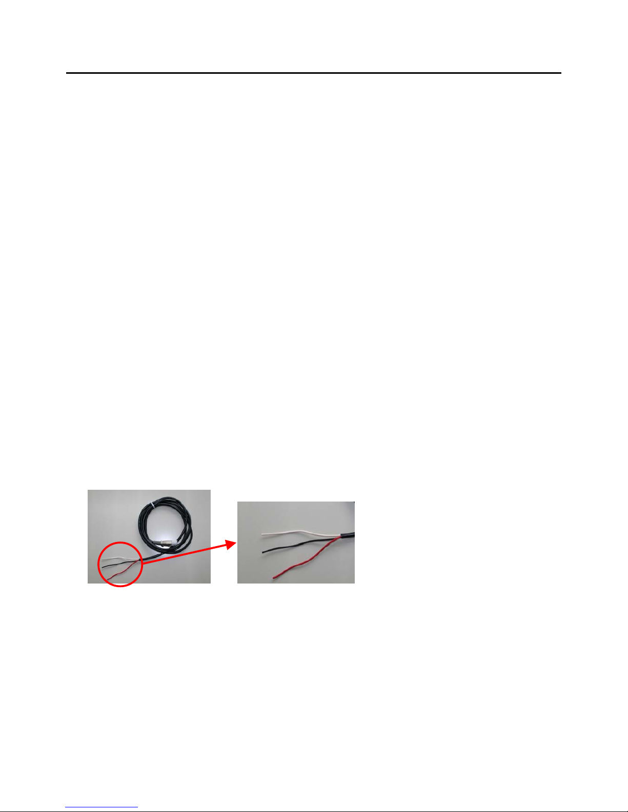
Power cable in accessories
This cable for external power for the receiver.
The cable consist of three kind of color f conductors
i.e. color is red(Plus +) , black(Minus -) and white (Non connection)
3
Page 5

4
LED lamp
<EXT.POWER>
Green The voltage of external power supply more than 11.3V
Red The voltage of external power supply less than 11.3V
When voltage around 11.3V, LED lamp blight alternately about green an d re d color.
NOTE: This value of voltage used with power cable (1.25 sq,2m) in standard accessories)
<INT.BATT>
No lighting The voltage of internal battery more than 10.3V
Blinking with red color The voltage of internal battery less than 10.3V
------------------------------Lighting with red color Defective of internal battery
CAUTION:
The voltage of internal battery decrease Blinking with red color.
In this case, please connect to the external power supply with stable immediately the please charge
the internal battery.
If the internal battery is defective when ramp-up period, the red color lamp lights.
In this case it necessary replace new battery.
Page 6

5
Color of LED lamp
<EXT. POWER >
Green : more than 11.6V of voltage value of external battery.
Red : less than 11.6 V of voltage value of external battery.
When voltage around 11.6V, LED lamp blight alternately about green and red color.
< INT.BAT >
No lighting :
More than 10.5 V of voltage value of back-up battery. (This is normal condition)
Blinking with red color :
less than 10.5 V.
(Connect external power source and re-charge back-up battery immediately.)
Lighting with red color :
Defective of back-up battery. (Replace back-up battery immediately)
The voltage of internal battery decrease Blinking with red color
In this case, please connect to the external power supply with stable immediately
the please charge the internal battery
If the internal battery is defective when ramp-up period, the red color lamp lights.
In this case it necessary replace new battery.
Page 7

6
WRITE/LAN button
The lamp of the "WRITE/LAN" button becomes a slow blinking while the connection to PC by the
communication protocol and also during establishment of connecting with PC.
(Do not blink in the connection with the panel software. )
It is possible to write it in USB memory even insert the USB memory during LAN connection and as usual
though a slow as it is blinking is continued.
The lamp returns to a slow blinking after the end of work of writing.
Page 8

Write to USB Memory
Measured data
The J-chip mini receiver create new file when start of measurement and store the measured data.
It can write these measured data to USB memory by press the “WRITE/LAN” button.
Created File : ‘Dxx.yyy’ xx:PC-ID yyy:Serial no.
Ex: PC-ID is 1 and File No. start from 005
Start of measurement File(’ D01.005’) Open.
(During measurement) WRITE/LAN File(’D01.005’) write to USB memory stick
End of measurement File(’ D01.005’) Close.
WRITE/LAN File(’D01.005’) write to USB memory stick
Start of measurement File(’ D01.006’) Open.
WRITE/LAN File(’D01.006’) write to USB memory stick
.
(During measurement)
WRITE/LAN File(’D01.006’) write to USB memory stick
End of measurement File(’D01.006’) Close.
WRITE/LAN File(’D01.006’) write to USB memory stick
Information of the receiver
Write the information of the receiver with measured data every time.
Created File : ‘Cxx.txt’ xx:PC-ID
Written contents The elapsed date with measuring clock.
The IP address of the receiver.
The name of the receiver.
The version of receiver firmware.
The version of firmware of trigger board.
The version of firmware of power supply board.
NOTE:
The lamp on WRITE/LAN button is blinking when writing in USB fails.
Depend of the USB memory, it might succeed with pushing the WRITE/LAN button again even
writing fails. (It is thought the error of the USB memory itself two or more times when not
succeeding even if it tries.)
7
Page 9
Panel soft
Instration
The panel soft created by JAVA.
Please install JAVA(RunTime) in PC used in advance.
Please copy the “JChipMiniCP.jar” to appropriate directory as the panel soft not necessary other special
installation
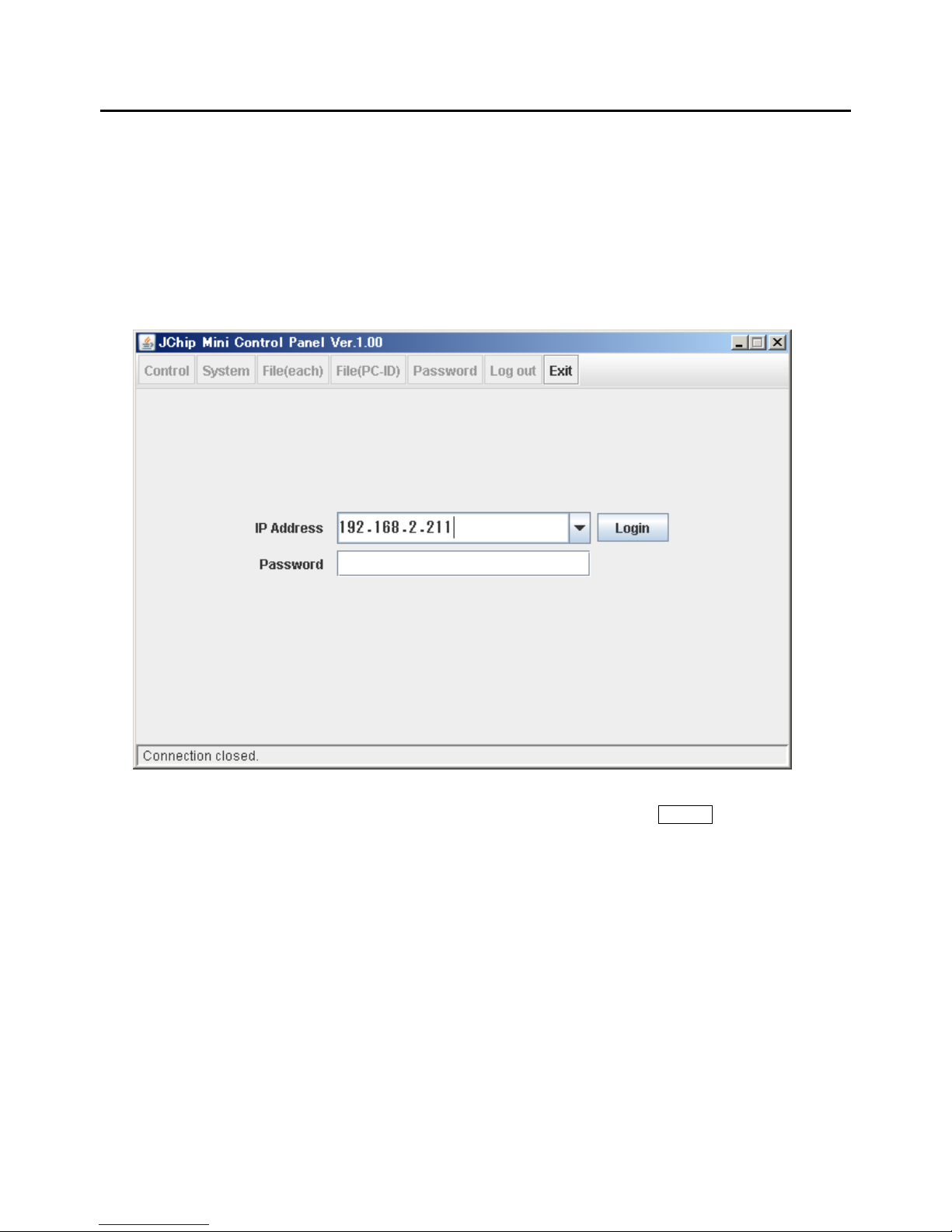
Boot-up and connection
Boot-up the “JChip MiniCP.jar”.
Please specify the IP address of the receiver in “IP Address” then press the Login button.
The default of password is No use.
If password necessary, it can specify in this panel soft.(Please see “Setting of password”)
The initial value of the receiver for network relation.
IP address 192.168.2.211
Net mask 255.255.255.0
Default gateway 192.168.2.254
Please adjust the network address of the PC that connects it to the receiver.
8
Page 10

Operation(Control)
The start/stop of measurement, automatic tuning, setting of the measuring clock
and power supply (external and internal) information is displayed.
Measurement Start/Stop (Measuring SW)
Status: No measurement
Press Start then start the measurement.
Status: Measure
Press Stop then stop the measur em ent.
9
Page 11

Trigger ON/OFF and Turning(Trigger SW & Trigger Settting)
Status: Trigger OFF
Press On then Trigger ON.
When the trigger is turning off, the button fo
r
the tuning is invalid.
Status: Trigger ON
Press Off then Trigger OFF.
When the trigger is turning on, the button fo
r
the tuning is valid.
Press Auto Tuning then start tuning
automatically.
Press Manual Tuning then the menu o
f
manual tuning is displayed.
Manual Tuning
Adjust the value of resistance (Resistance)
and value of capacitance(capacitance) then
press Apply .
Trigger level(Level)
When the display is “0” that the trigger signal is
not transmit. Please tuning again after the
installation situation of the trigger antenna are
confirmed
The output level of trigger signal changes by the
situation of installation of the trigger antenna. Please
test reading that uses J-chip tag in the place used
and confirm the trigger area after the tuning.
10
Page 12

Display of the measuring clock (Measuring clock)
The measuring clock is displayed.
The “x day” displays the elapsed days.
In case of manual setting, set the date, time
and elapsed days then press the Apply .
Press Sync PC then a djust the time at the
time of PC.
In this case, the elapsed days is “0”
Day (elapsed days) :
The number of days increment when becoming the time of 23:59:59 to 00:00:00 while
measurement.
It is days that .."1".. increase when becoming 00:00:00 from 23:59:59 while measuring it.
Please specify it if necessary.
Offset (Value of offset)
Please specify the value of offset when set time of the clock, if it necessary.
Display of received data (Received Data)
Tag ID
The last received data is displayed.
Count
The number of received data from start of measurement are displayed.
(Even if the same tag is read, it is counted.)
11
Page 13

Display of information of power supply (Power) and the power supply alarm
The value of voltage of the external power supply
The value of voltage of the internal battery
NOTE
Both value are through internal circuit
The both above value are not the external power-supply voltage directly nor the value of the voltage
of the terminal of built-in battery because the both value passed internal circuits.
The power supply alarm
When the voltage value of the external source becomes 11.3V or less, it is displayed in red color.
In this case, please replace the external power supply immediately.
12
Page 14

Setting of system (System)
Setting of general (General)
After changing each parameter Apply is pressed and the content is reflected.
The contents of setting are displayed from the receiver again when press the Restore .
PC-ID/Next File Name
To Set of PC-ID of the receiver. “PC-ID” can set in ranges from “00” to “99”
The name of file which file is store of measuring data when start of next measurement display at
“Next File Name”.
Tag Prefix
The specified letter at this menu add to top of tag ID read by the receiver
It can set in ranges of from “A” to “Z”
Example: T AG ID 123456 Tag Prefix A A123456
Holding Time
To set time for ignore the same Tag ID.(From 0 – 60 second)
Even the same Tag ID comes during time appointed in this item, the receiver is not read it.
This function is not available when setting of time is “0”
Measure at
To set of timing of measurement
Both “Beginning Time Time” and “Mid Time” are available.
Beginning Time The time data measure when this was in the trigger area.
Mid Time The time data measure by calculation to middle point from
two kind of data. i.e. J-chip tag is in the trigger area and it is out from this area.
13
Page 15

Setting of Network
After changing each parameter Apply is pressed and the content is reflected.
The contents of setting are displayed from the receiver again when press the Restore .
Device name
Setting of name of the receiver.
The usable letter for the name of reciber that it is ASCII alpha-numerical within 32 characters and
“+(Plus)”, “-(Ninus)“ , “_(Underscore)”.
Set it to unique name when use plural receivers in same network.
IP Address
To set the network parameter of the receiver itself.
Listen Port
To set the port number which the receive wait for connection.
CAUTION
Please boot up the receiver again when change the network
14
Page 16

Setting of connections
The setting for connection to the host. "Server/Client" can be individually selected in 8 locations max..
Please put the check in Use of the place used on screen.
After changing each parameter Apply is pressed and the content is reflected.
The contents of setting are displayed from the receiver again when press the Restore .
When the setting at the access point is changed, the place of the object is chosen and press Edit .
The screen after it changes is displayed.
Type
Choose connection type.
Remote IP address/Remote Port
The set of the IP address of and the port.
When the connected type is "Client", other party's IP address and port are set.
15
Page 17

Information of system (System)
Release Vaersion
The version of firmware of the receiver
Automatic measurement start (Auto Start)
The receiver is trigger ON + automatic tuning when boot up and automatically start measuring when
there is a check in check box.
The measurement doesn't start automatically since next time after boot up, if the check is removed
from check box.
Update of the firmware(Firmware Update)
Please specify the file for the update as menu of selection is displayed when press Select File
(The file for the update provide as needed. )
Re-boot
The receiver reboots when press Reboot Now .
16
Page 18

Control of log file –Unit of the file(File each)
Display
The measurement data file stored by the receiver is displayed.
It can permute the position from sequentially presented data file when click File Name and Time
stamp.
The only file of PC-ID are displayed when specify “Filter by PC-ID” to PC-ID.
If ALL is selected, all files are displayed.
Download
The file that wants to be downloaded to PC is selected and Download is pressed.
The file name selection dialog is displayed and please specify the file.
Delete
The file that wants to be delete is selected and Delete is pressed.
Two or more files can be selected if it selects it while pressing Shift Key or Ctrl key.
17
Page 19

Control of log file –Unit of the PC-ID (File PC-ID)
Display
The measurement data file stored by the receiver is displayed by unit of the PC-ID.
Each PC-ID has been arranged in the file of the ZIP format.
The stored number of files is displayed in File Count.
It can permute the position from sequentially presented file when click PC-ID, Latest Date time.
Download
The file that wants to be downloaded to PC is selected and Download is pressed.
The file name selection dialog is displayed and please specify the file.
(The downloaded file is ZIP format.)
Delete
The file that wants to be delete is selected and Delete is pressed.
Two or more files can be selected if it selects it while pressing Shift Key or Ctrl key.
18
Page 20
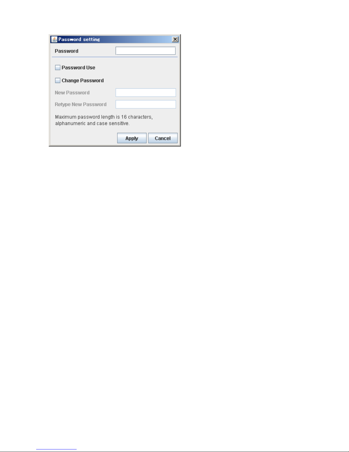
Setting of password (Password)
Please input the password when change the setting.
The initial password is 1234.
If "Password Use" is checked, the input of the password is needed when login.
If put check to Password Use, it necessary input the password when login.
If change of the password, please check to"Change Passwrord" and specify the password newly
changed.
The password is needed in the alphanumeric character by 16 digits.
(The alphabet distinguishes capital letters and small letters. )
* Please manage the password for remembrance' sake.
19
 Loading...