

Page 1

WinCNC Controller
WinCNC Controller 2.6
Revision 1
Copyright © 1999 - 2013
Microsystems World CNC, LLC
14 East Lincoln Street, Buckhannon, WV 26201
(304) 472-7206
Microsystems World CNC, LLC makes no warranties either ex-
pressed or implied, including any implied warranties of tness for a
specic purpose, for this software. This package is provided solely
on an “as is” basis. All risk involved in the use of this software is the
responsibility of the purchaser.
Program errors, improper software conguration, hardware failures,
or other problems can result in damage to the machinery being
controlled. Failure of limit switches, cabling, or port components can
result in machine movement past limits, potentially damaging the
machine and endangering operators. It is imperative that a separate
Emergency Stop system be in place, which bypasses all computer
control. Software features to abort motion from the keyboard and
limit switch inputs are provided as conveniences only, and must not
be relied upon to stop motion in an emergency.
Microsystems World CNC, LLC disclaims all liability for any and all
damages, including incidental and consequential damages in con-
nection with use of this software. The sole and exclusive liability of
Microsystems World CNC, LLC will be limited to the purchase price
of this software package.
If you do not understand and agree with these disclaimers, please do
not use this product. Return all materials to the place of purchase for
a full refund.
WinCNC Users Guide Page 1
Page 2

WinCNC Controller
3 Hardware & Software Installation
9 Program Operation
43 SystemConguration
73 ScreenConguration
81 Command Reference
109 MacroConguration
111 Messages and Error Codes
117 KeypadConguration
123 Appendix
129 Index
Contents
WinCNC Users Guide Page 2
Page 3
WinCNC Controller
Installation
CAUTION: DO NOT USE THIS SOFTWARE ON A COMPUTER
CONNECTED TO A MACHINE UNLESS THERE IS AN EMERGENCY STOP READILY AVAILABLE WHICH WILL INDEPENDENTLY
STOP THE MACHINE.
Software features to abort moves from the keyboard and limit switch
inputs can NOT be relied upon in emergency situations and are provided as conveniences only!
Requirements
WinCNC Controller 2.6 requires a Windows XP/Vista/7/8 (32 or
64 Bit) computer system with Pentium IV or faster processor, 1GB
or more of RAM, a hard drive, and an enabled USB port. Slower
computer systems may result in abnormal acceleration and other
problems. An Internet connection is highly recommended to ensure
proper technical support and access to Windows Updates from
Microsoft.
HardwareInstallationandCongurationofthePCI-7200Card
**It is highly recommended that you use an anti-static wrist strap
before handling any components.
Installation
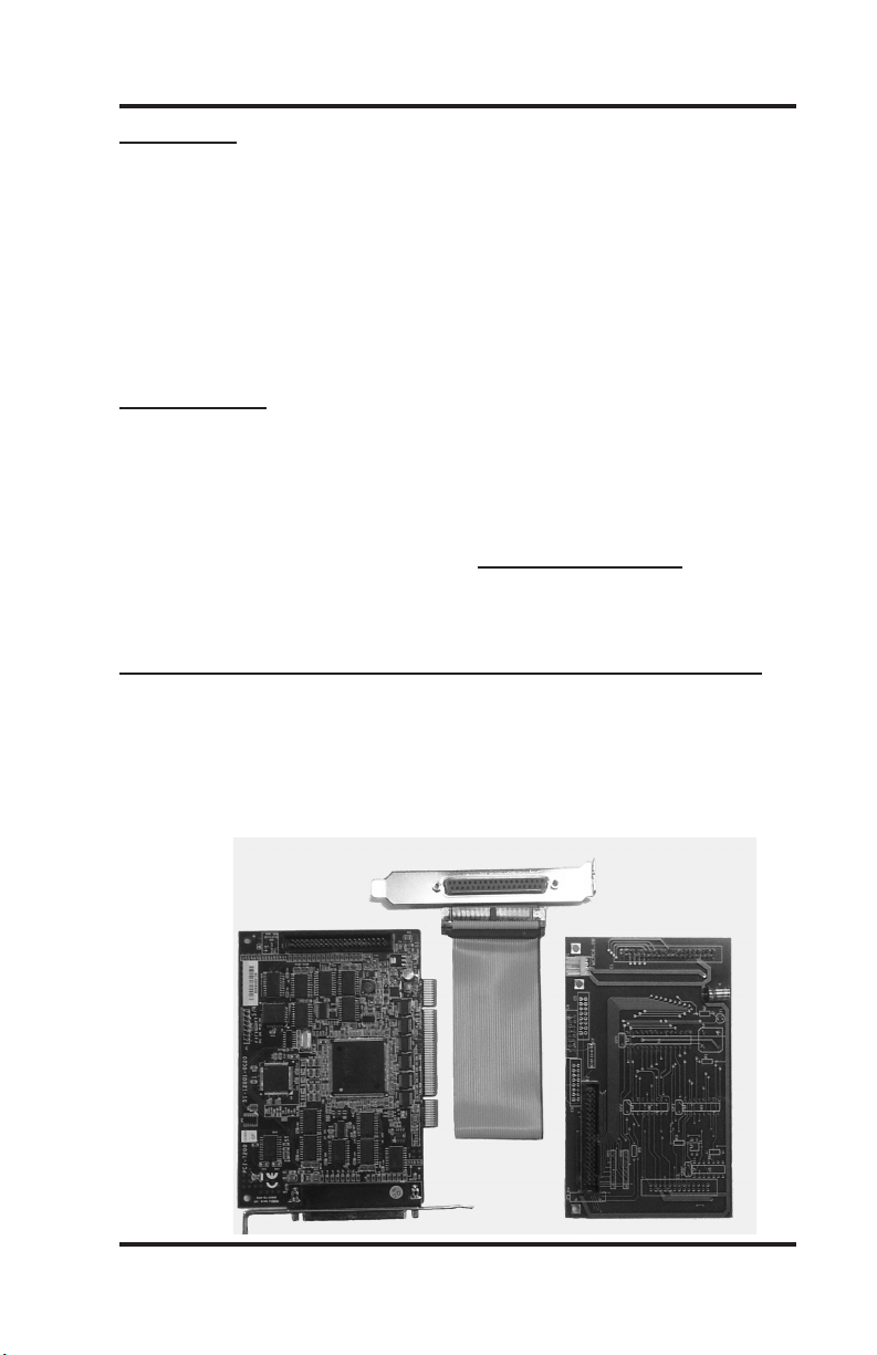
Below are the components for the PCI-7200 installation. These
include a PCI-7200 card, a Daughter Board, and a ribbon cable
connector.
WinCNC Users Guide Page 3
Page 4
WinCNC Controller
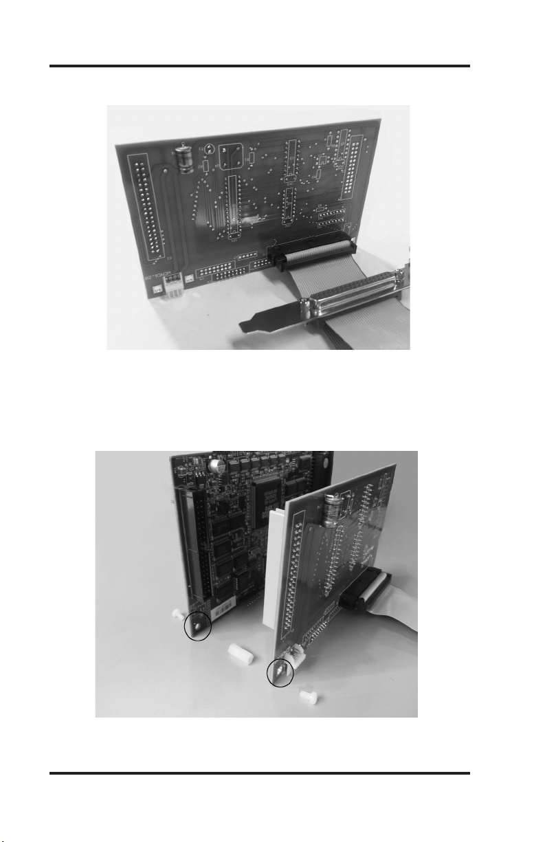
Insert the ribbon cable connector into the Daughter Board.
Below is the PCI-7200 card on the left, the Daughter Board on the
right and the spacer/screw assembly. Note the matching holes in
the corners of the Daughter Board and the PCI-7200 card. This may
already have been done prior to shipping.
Installation
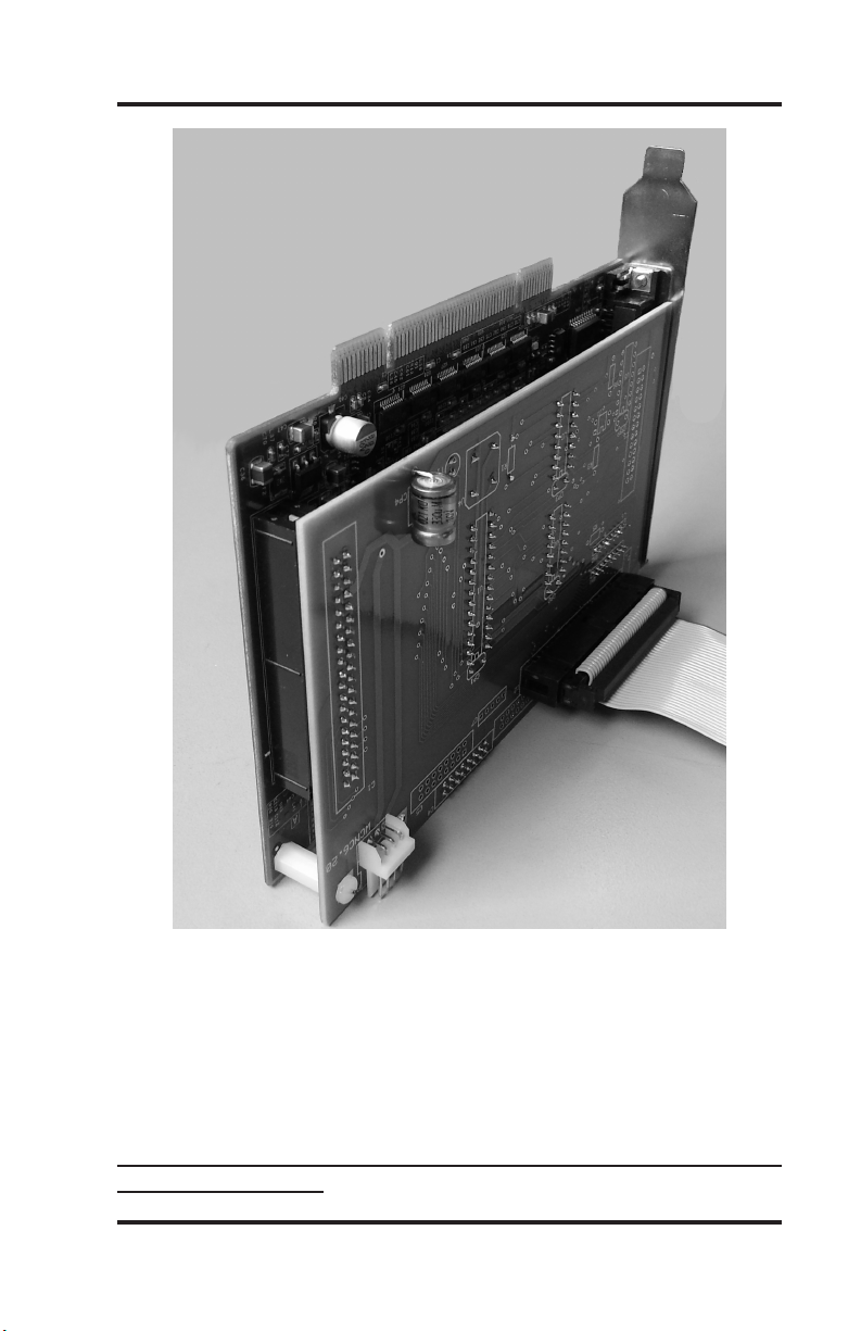
Insert the Daughter Board onto the 40-pin connector of the PCI-7200
card. Attach the two cards with the included spacer and screws. This
will insure constant connection between the two boards.
WinCNC Users Guide Page 4
Page 5
WinCNC Controller
Installation
Power down and unplug the PC from any power.
Insert the PCI-7200 card into an empty PCI slot on the motherboard.
Install the extra 37-pin connector into an empty cover slot. Install the
extra 37-pin connector into an empty cover slot so that when you are
looking at the back of the computer, you have two identical 37-pin
ports, one being blue and the other black.
TheblueDB37connectoristhedaughterboard,andtheblackis
thePCI-7200card.
WinCNC Users Guide Page 5
Page 6

WinCNC Controller
Installation
Very Important! Install the 37 pin cable from the control box into
the daughter card (BLUE) connector, not the PCI (BLACK) connector. The cards have different power and ground pins and the cards
will be damaged if connected incorrectly.
Make sure the PCI-7200 card is using its own IRQ. IRQ settings
must be altered from the BIOS to insure no conicts occur between
the PCI-7200 card and other system resources. Changing these settings from within Windows alone will not insure this.
After installing your PCI-7200 card and the extra connector, boot up
your computer for driver and software installation.
**Note: When your computer boots up, you may get a hardware
installation wizard. Close it. You will be installing the driver after the
software is installed.
Install software
Insert the WinCNC Controller CD-ROM into the CD-ROM drive. If
the installation does not automatically start, you will need to manu-
ally run the “Setup.exe” le on the disk. To do this, click “START”,
then “My Computer”, then right click on the ‘D:, E:, or F:” drive that is
labeled ‘WinCnc.”. You should get a menu that pops up.
On that menu, click “Explore”. Once the les on the CD are visible,
double click the “Setup.exe” le. Follow the prompts of the installation wizard. The install routine will create the specied directory if it
does not exist and copy the necessary les into it. If there is a previ-
WinCNC Users Guide Page 6
Page 7

WinCNC Controller
ous installation of WinCNC controller the les will be overwritten.
DriverInstallationforPCI-7200Card:
**Normally,driverinstallationisdoneautomaticallybythe
installationCD.
Forsoftwareversion2.4.xx:
A driver is required for the PCI-7200 card. The driver is included in
the PCI-7200 folder on the root directory of the WinCNC installation
disk for user convenience. If the installation disk isn’t available, the
driver can be downloaded from the Microsystems World CNC web
site. After connecting to the internet, go to www.wincnc.net and click
on the “Support” link at the top left of the page, then click “Downloads”. Next, nd the “CNC Windows/” link and click that, then click
“Device Manager”, click “2.4”, then click “PCI7200”, and nally click
“PCI7200.exe”. Next click “Save” and browse to your desktop, and
then click “Save” again. Once the download is complete, click “Run”,
and then “Run” again. Make sure at this point, that you “browse” to
the WinCNC folder on your C:\ drive before clicking “Unzip”.
Go into the PCI7200 folder inside of the WinCNC folder and nd
“uninstdrvr.bat”. Run that le, and be careful not to close it before it
is done. Watch for prompts asking you to press a key to continue.
After that is done, run “instdrvr.bat”. Same thing.... either or both of
these may take longer than you think, and may pause and not do
anything long enough for you to think it might not be working correct-
ly. Sometimes those two les run fairly quickly, but there have been
instances when they take a couple of minutes to complete.
Installation
After running both les, reboot your computer and try opening
WinCNC.
Run the program by double clicking on the WinCNC icon on your
Windows desktop.
WinCNC Users Guide Page 7
Page 8
WinCNC Controller
Forsoftwareversion2.5.xxor2.6.xx:
In the WinCNC folder, there is a le named “driverinstaller.exe”. This
should be the only le you need to run in order to install the PCI card
drivers. Double click on this le to run the driver installer program
which will automatically detect the operating system and install the
correct device driver (32 bit or 64 bit). After the program is nished,
reboot your PC, and the driver should be installed correctly.
Toverifythecorrectinstallationofthedevicedriver,forall2.4,
2.5,and2.6versions,dothefollowing:
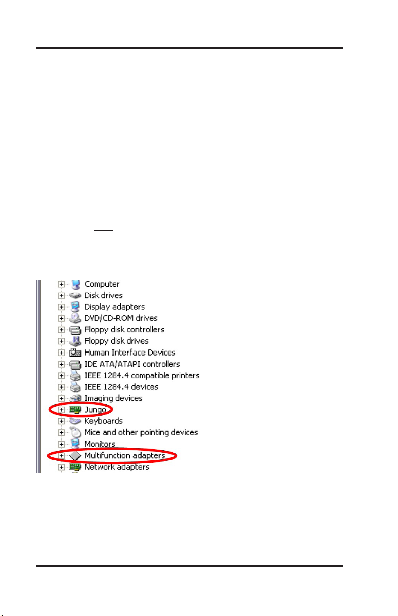
Click “Start”, right-click on “My Computer”, click “Properties”. Then
nd the “Hardware” tab, click it, then click the “Device Manager”
button. In the Device Manager list, there should be two components
as shown and circled below.
Installation
WinCNC Users Guide Page 8
Page 9

WinCNC Controller
Overview
WinCNC Controller has advanced features to provide the smoothest
possible cuts. G-Code input is constantly buffered to ‘vector match’
moves. This means your machine only slows down when it needs
to and then only as much as needed to stay within the acceleration
parameters programmed. WinCNC Controller also does S-Curve
acceleration through arcs and matches arc tangential velocities with
straight moves to provide smooth arc moves. The result of these
features is simply smoother cuts and less need for nishing operations. WinCNC Controller has a highly customizable, user-friendly
interface that lets you take control of your machine, providing fea-
tures previously only found on custom industrial controllers.
Any stepper, micro-stepper, or servo system with step and direction
inputs can be interfaced using the included PCI card and microprocessor daughter board, or one of several available PCI I/O expansion cards. In addition to axis motion, up to 128 auxiliary outputs
and 128 separate inputs may be dened. The intuitive user interface
is easy to learn and convenient to use. All the features you need and
expect are readily accessible via industry standard G-Codes. Simple
keystrokes provide the ability to start, pause, restart, jog, and rapid
transit any axis without navigating multiple screens and windows.
Programs may be run from any line as needed. The programmed
feed rates may be adjusted from 1% to 200% without stopping ma-
chine motion.
Program Operation
Run the program by double clicking the WinCNC icon on your Win-
dows desktop. Program options may be selected from the pull down
menu using the mouse, ALT+ menu key, or function keys while the
machine is stopped. Files can either be typed into the command line
or you can use the File menu’s open option to bring the le name to
the command line. Using the open command does not automatically
run the le, it just brings the name to the command line.
WinCNC Users Guide Page 9
Page 10
WinCNC Controller
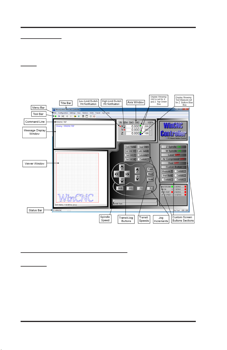
ScreenDisplay
The following section contains a sample of the WinCNC software
display. Common components are labeled to provide clarity.
NOTE : This screen may differ from your screen layout, as it is
highly customizable and may have been altered by the CNC ma-
chine manufacturer.
Program Operation
ScreenDisplayComponentBreakdown
MenuBar
The Menu Bar contains many of the main features of the WinCNC
software. It is broken down into several generalized sections, as
shown below. The menu bar selections are described in the following pages. If a menu option has a shortcut key, the shortcut key
combination is listed in parenthesis () after the name of the menu
option.
WinCNC Users Guide Page 10
Page 11

WinCNC Controller
FileMenu
Open (CTRL+O) - Opens a le.
Edit (CTRL+E) - Opens the editor. If a lename is in the command
line, the editor opens that le.
Simulate (CTRL+S) - Simulates a le running to check for errors and
estimate run time.
View (CTRL+V) - Views a le in the viewer window.
Restart (CTRL+R) - Opens the le restart dialog box to restart a le.
Create Home File (CTRL+H) - Creates a home le at the current
machine position.
Import=>DXF - Allows the user to import DXF (Drawing Exchange
Format) le.
Import => HPGL - Allows the user to import HPGL (Hewlett-Packard
Graphics Language) le.
Program Operation
*Note: The DXF and HPGL import feature is intended for cutting
simple designs. WinCNC does not compensate for tool diameter
when converting these les. For more complicated design, where
intelligent tool pathing is important, please use a compatible CAD/
CAM program.
Digitize=>Manual - Enable/Disable the Manual Digitizing Toolbar.
Digitize=>Automatic - Automatic digitizing (L802, L803).
Digitize=>Frame - Skeletal Digitizing (L810). This scanning
method scans a center line or spine, and horizontal lines or ribs of
the object.
Digitize=>Outline - Creates an outline trace around an object.
WinCNC Users Guide Page 11
Page 12

WinCNC Controller
Digitize=>Laser=>RunScan - Opens the laser digitization dialog
box to set up laser scanning parameters.
Digitize=>Laser=>ReprocessData - Opens a data le from a
previous laser scan used to re-generate a 3D object with different
ltering options to improve the quality of the 3D object.
Exit - Closes WinCNC.
CongurationMenu
D/ACalibration - Calibration Settings for D/A (Digital to Analog)
spindle speed control. This can only be used if D/A has been activated in the WinCNC Program.
SettingsMenu
Positions - Opens the positions dialog box with options to view and
edit stored positions. (Ex: G53 P# to call position in G-Code)
Home Positions - Opens the positions dialog box with options to
view and edit stored home positions. (Ex: G0 H# to call home pos.)
Program Operation
Tool Positions - Opens the tool positions dialog box with options to
view and edit stored tool positions for use with automatic tool chang-
ers. (This requires an additional software feature to be enabled)
ToolLibrary - Edits and views the dened tool library.
Local Coordinates - View XYZ coordinates.
ViewMenu
Resolution - View current resolution settings for each axis.
Acceleration - View current acceleration settings for each axis.
Limits - View current limit settings for each axis.
Inputs- Views real-time input states.
Outputs - Views real-time output states.
WinCNC Users Guide Page 12
Page 13

WinCNC Controller
Toolbars- Enable/Disable the main toolbar.
Toolbars=>Size-Change toolbar from small to large.
RefreshView(F5) - Refreshes the screen.
Clear Screen (CTRL+C) - Clears the message display window.
OptionsMenu
Soft Limits (CTRL+L) - Enable/Disable the software limits.
Keyboard (CTRL+K) - Enable/Disable the keyboard transit/jog control used to move the machine with the keyboard.
Buttons - Used to customize user buttons.
AutoRepeat - Auto populate the command line with the last com-
mand executed.
AutoRun - Enable/Disable the auto run feature.
AutoPreview - Enable/Disable the auto preview feature.
Program Operation
Single Step (CTRL+P) - Enable/Disable single line execution of G-
Code les.
UnitsMenu
Inches - Sets the unit of measure to inches.
Centimeters - Sets the unit of measure to centimeters.
Millimeters - Sets the unit of measure to millimeters.
TransitMenu
Slow (F2) - Sets the transit speed to slow.
Medium (F3) - Sets the transit speed to medium.
Fast (F4) - Sets the transit speed to fast.
WinCNC Users Guide Page 13
Page 14
WinCNC Controller
JogMenu
0.001 (F6) - Sets jog increment to 0.001 units of measure.
0.01 (F7) - Sets the jog increment to 0.01 units of measure.
0.1 (F8) - Sets the jog increment to 0.1 units of measure.
1 (F9) - Sets the jog increment to 1 unit of measure.
Custom (F10) - Allows the user to set a custom jog increment.
HelpMenu
Help Topics (F1) - Activates the in-program help menu.
Update Program - Opens the update utility.
About - Displays the WinCNC “About” box which contains important information about your specic software package. The About
box displays your security key serial number, the software version
number, your user level, the maximum number of axes, the table size
limitation, and which additional features you have enabled. If you
do not have a feature enabled that you would like or need, you can
contact your software vendor for an upgrade.
Program Operation
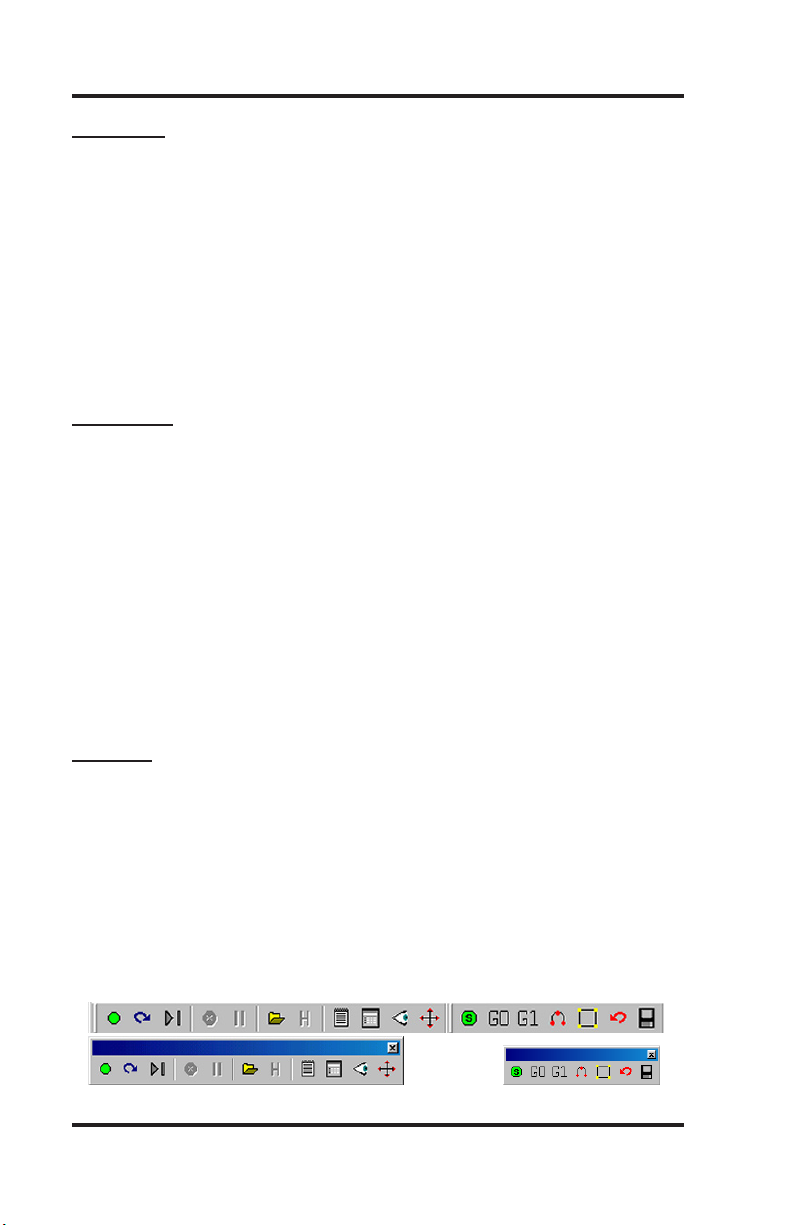
ToolBar
The tool bar is a collection of shortcut buttons that perform specic
actions. The toolbars in WinCNC are oating and can be positioned
or docked to the user’s preference. The image below shows both the
standard and manual digitizing toolbars both docked in the normal
toolbar area. The additional images show each toolbar separately
as a oating toolbar. The explanation of each button on the toolbar
is as follows. The explanations move sequentially from left to right
along the toolbar.
WinCNC Users Guide Page 14
Page 15

WinCNC Controller
Start Motion - This button will begin the command or job listed in the
command line.
Restart - Allows you to pick a job le and the line to start that le on.
This is useful if you want to skip over lines in a job le, or if you have
aborted a job and want to start back at the point you aborted from.
You can also choose to run the le in single step mode.
Single Step - When selected, this allows you to execute one line of
a G-Code le each time you hit ENTER.
AbortMotion - Aborts a command or job that is running.
Pause/ContinueMotion - Pauses/Continues a command or job that
is running.
Open File - Opens a browse box that is used to open a job le.
View History - Opens the command history box, which allows a user
to execute a command used previously. When an error is found in
the WINCNC.INI le, the line containing the syntax error is displayed
here in red when WinCNC starts.
Program Operation
Edit - Opens the default editor specied in the WINCNC.INI le.
WinCNC uses Notepad by default. The editor can be used to open
job les, listed in the command line in the editor.
Simulate - Simulates a le to check for errors and run-time.
View - Opens a le for viewing in the viewer window.
Soft Limits - Enables/Disables Softlimit features.
ManualDigitizeButtons - The seven buttons on the manual digitization toolbar are for use only with the Manual Digitize feature, and
will only be visible after showing the manual digitize toolbar under
the View->Toolbars section of the menu bar.
StartaManualDigitizedFile - Starts a manual digitized le and
enables the manual digitize mode.
WinCNC Users Guide Page 15
Page 16
WinCNC Controller
AddaRapidMove - Adds a rapid move to the manual digitized le.
AddaFeedMove - Adds a feed move to the manual digitized le.
Add an Arc Point - Used to add arcs into a manual digitized le.
CloseShape - Used to close the last move in a shape without mov-
ing the machine.
Undo - Used to undo previous moves.
Save - Allows you to save the manual digitized le in either G-Code
or DXF le format.
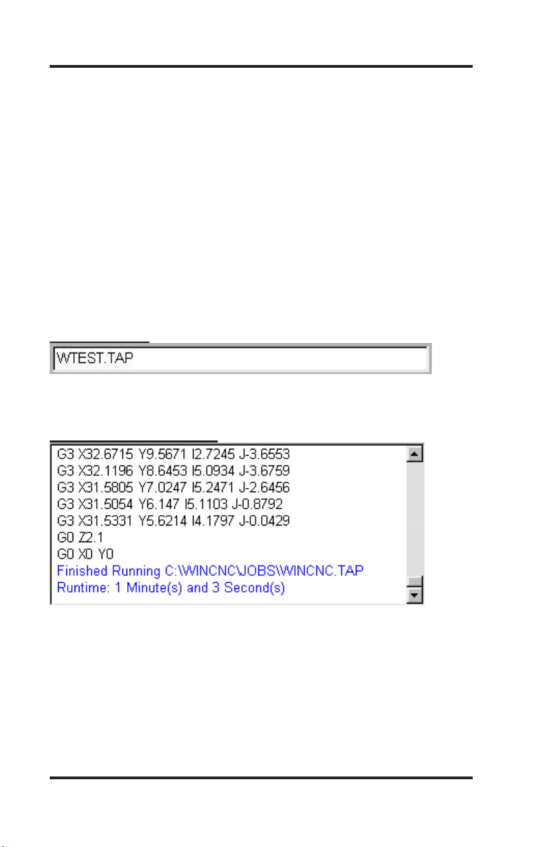
Command Line
The command line is the input line for users to enter commands or
job les to be executed.
MessageDisplayWindow
Program Operation
The message display window is the main output window displaying
the commands that have been executed, messages to the user, or
errors that have occurred during an operation.
WinCNC Users Guide Page 16
Page 17

WinCNC Controller
Axis Window
The axis window is the primary display for current information about
each axis on your machine. The current positions and velocities for
each axis are displayed in the text boxes. Displayed above the posi-
tion and velocity boxes are the current units of measure, any current-
ly active modes, and the current feed rate override percentage. Red
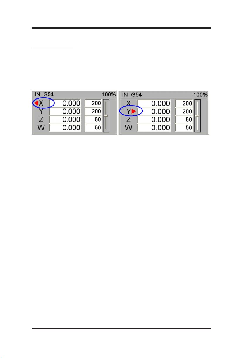
triangles to the left and right of each axis label indicate low or high
limit switch hits. A red triangle to the left of an axis label indicates a
low limit switch hit, and to the right indicates a high limit switch hit.
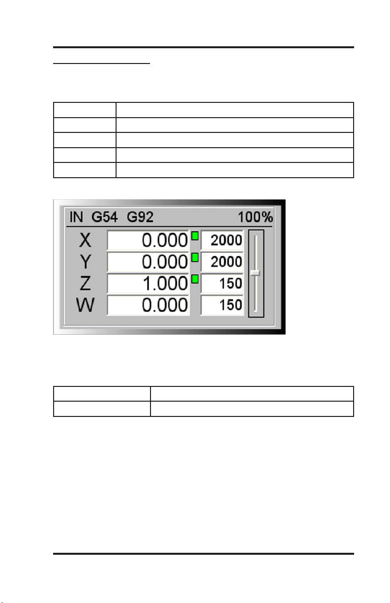
A green box displayed to the right of the position box indicates a
temporary workspace (G92) setting, and a blue box indicates a tool
length measure or workspace setting. To the far right side of the axis
window is the feed rate override control slide bar.
Program Operation
TransitSpeedButtons
These buttons allow you to specify the transit speed of
your machine.
Fast transit is the default.
In the cncscrn.ini le, change the “default speed” eld to
1, for the speed you would like to be default, all others
must stay 0.
Ex: for default medium speed, use the following:
“JogMode”, 0,5,35,25,7,1,”Med”,””,””,-1,-1,”med.bmp”
JogIncrementButtons
These buttons allow you to specify the increment of a jog move.
WinCNC Users Guide Page 17
Page 18
WinCNC Controller
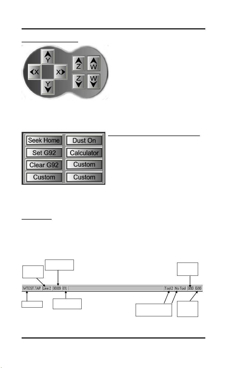
Current File
Percentage of File
Completion
G00/G01
Mode
Indicator
Elapsed Time for
Current File
* Note: There are TWO t ool
changer indicators
Tool Changer ON/OFF
and current tool being
used
G90/G91
Mode
Indicator
Current
Line in Job
File
Program Operation
Transit/JogButtons
These buttons are what allow you
to initiate a manual transit or jog
movement from the console of the
computer that runs the machine.
In transit mode, holding the button
down will continuously move the
machine. In jog mode, each time a
button is pressed the machine will
move according to the jog incre-
ment that has been selected. Holding the button down in jog mode
will move the machine only once.
CustomScreenButtonsSection
This section of controls is a customizable button section that allows
the user to place shortcut buttons to
activate heavily used commands.
Note: See Section 4 Screen Conguration
StatusBar
The status bar is the label along the bottom of the WinCNC window
that looks similar to the one shown below. This bar provides the user
with the status of several features in WinCNC. Each section in the
example below is labeled for clarity.
WinCNC Users Guide Page 18
Page 19
WinCNC Controller
ShortcutKeys
FileMenuShortcuts
Open Enter (with blank command line), CTRL+O
Edit CTRL+E
Simulate CTRL+S
View CTRL+V
Create Home File CTRL+H
ViewMenuShortcuts
Refresh View F5
Clear Messages CTRL+C
OptionsMenuShortcuts
Keyboard CTRL+K
Soft Limit CTRL+L
TransitMenuShortcuts
Slow F2
Medium F3
Fast F4
Program Operation
JogMenuShortcuts
.001 F6
.01 F7
.1 F8
1 F9
Custom F10
HelpMenuShortcuts
Help F1
WinCNC Users Guide Page 19
Page 20
WinCNC Controller
ShortcutKeyscontinued
ToolBarShortcuts
ESC Aborts the current le or command
SPACE Pauses a le or command
ENTER Starts/restarts a le or command
TAB Opens the command history box
CTRL+R Opens the restart le box
FeedRateOverrideShortcuts
INSERT Increases override rate
DELETE Decreases override rate
CTRL+either Resets feed rate to 100%. No over-
ride settings
ManualDigitizeShortcuts
After opening the Manual Digitize toolbar and clicking the green
start button, the following shortcut key combinations become active
for adding moves to the digitized le.
Add Rapid Move CTRL+J
Add Feed Move CTRL+F
Add Arc Midpoint/Endpoint CTRL+A
Undo Last Move CTRL+U
Close Current Shape CTRL+D
Save CTRL+W
Program Operation
SpindleSpeedandLaserPowerShortcuts
Spindle Speed Alone or
Laser Power Alone
Spindle Speed and Laser
Power Together
CTRL+(Function Key) See “ctrlf#=” in conguration settings
WinCNC Users Guide Page 20
+ - (plus and minus)
Laser Power uses + Spindle Speed uses Shift + -
Page 21
WinCNC Controller
LimitSwitches
The default channel settings will normally provide proper interfacing
with the machine’s limit switches. Before attempting to move the
machine, verify that all limit switches are functioning properly. Limit
switch status is displayed in the position window using a red triangu-
lar indicator to the left or right of the axis label.
Program Operation
The indicator to the left of the axis label shows low limit status for
that axis. The indicator to the right of the label shows high limit
status. If the indicator is present then the limit switch is closed,
otherwise it is open. The lim_mode setting is used to control how
WinCNC responds to limit switch triggers.
First toggle your limit switches by hand. Verify that the appropriate
limit display toggles. If it does not toggle then you need to adjust WINCNC.INI. See the WINCNC.INI reference sections of the
manual if the default settings are incorrect for your machine.
It is recommended that you verify limit switch operation at the beginning of each session. Do not attempt movement until the limit switch
displays toggle correctly. Once the limits are working try a small
move. If nothing moves, the wrong axis moves, or movement is in
the wrong direction then adjust WINCNC.INI.
Perhaps the easiest way to do preliminary testing of movement is
with the Jog mode. Select “Jog .1”, and select the KEYBOARD option under the OPTIONS menu. If you are using the default jog key
conguration, use the LEFT and RIGHT arrow keys to move X, the
UP and DOWN arrows to move Y, the PAGEUP and PAGEDOWN
keys to move Z, and the HOME and END keys to move U. Otherwise use the buttons that are dened for your system.
WinCNC Users Guide Page 21
Page 22

WinCNC Controller
HomingtheMachine
When WinCNC Controller is started the display is set to the last
known position. If the machine has been moved manually or has
drifted while powered down, this position will not be accurate. The
G28 command must be used to home the machine. G28 moves the
WZ motors up to the high limits, then moves the XY motors to their
low limits. The heads are then moved away from the limits by the
values specied in WINCNC.INI and each axis is set to zero. This
position is Machine Zero.
It is important to use G28 to set Machine Zero since many WinCNC
features are calculated from this position. Soft Limits and Boundaries cannot be used if Machine Zero is not properly set. G28 will
search for the limits at 50” per minute. The “lim_step=” setting in
WINCNC.INI can help minimize the impact to the machine when
stopping at the limit switches.
G28 can also be used to home only specied axis. (i.e. G28Z homes
only the Z axis).
Normal machine operation using WinCNC Controller would be:
Start the program.
Enter G28. Push ENTER. (Machine Goes Home)
Enter part program to cut. Push ENTER. (Job le runs)
Program Operation
FeedRateOverride
WinCNC accepts feed overrides to increase/decrease the feed rate.
The feed rate can be adjusted from 1% to 200% of the programmed
rate. The override rate cannot be set higher than the max velocity
or G0 rate for a given axis. Use the Insert key to increase and the
Delete key to decrease the programmed feed rate, holding CTRL
and pressing either Insert or Delete will result in the feed rate being
reset to the programmed value. There is also a slider bar to the right
of the feed rate screen display that can be used to initiate a feed rate
override. The override feed rates will be displayed in place of the
programmed feed rates in the display. The feed rate will change colors to depict that an override is in use. If the override rate is higher
than the programmed rate the color of the feed rate display will be
red, if it is lower than the programmed feed rate it will be blue.
WinCNC Users Guide Page 22
Page 23

WinCNC Controller
Coordinate System
The Machine Zero (MZ) set by homing the machine becomes the
anchor point for all positions specied in subsequent G-Code commands. This is also considered absolute zero, not taking into account any temporary homes (G92’s) or tool measures.
Local Zeros (LZ) are set using the G92, G92.1 and G92.2 commands.
The position display box displays the current axis coordinates and
the axis coordinate modes. The axis coordinate mode is displayed to
the right of the axis position.
A green box indicates that the axis has a Local Zero applied. (G92,
or temporary home).
A blue box on a horizontal axis indicates that a workspace other than
G54 is in effect. (G55, G56, G57: ex: using W axis instead of Z).
A blue box on a vertical axis indicates that tool length measure is in
effect.
Program Operation
The coordinate modes show how the axis values in a given G-Code
command will be interpreted.
MZ Coordinates - values are relative to MZ. (Or absolute zero)
G92 Coordinates - values are relative to LZ specied by G92
(Ex: enter the command G1 X10 Y10, then enter. Next type G92,
then enter. X & Y will now show as x0, Y0)
G55, G56, G57 Coordinates for horizontal axes - horizontal axes
values are offset for vertical axes heads.
G43 Coordinates for vertical axes - vertical axes values are offset for
M37 tool measure values.
G92 and G55, G56, G57, G43 - values are offset for both.
WinCNC Users Guide Page 23
Page 24

WinCNC Controller
G91 Mode
G91 mode is called relative or incremental mode. In G91 mode values specify distances. For instance if the X position is currently 20
and G0 X8 is specied the machine would move +8 units of measure
in X to X28.
A G-Code program written in G91 mode may be run from any position. Since the moves are relative, the starting position does not
matter. The program will run properly from any starting position.
However, to get the proper results, the machine must be set to the
proper position in relation to the workpiece before the piece is run.
The axis coordinate status does not have any effect on how the program runs. It does however affect the coordinate display while the
program runs.
G90 Mode
G90 mode is called absolute mode. In G90 mode values specify
positions. If the X position is 20 and G0 X8 is specied the machine
would move -12 units of measure in X to X8.
Program Operation
In G90 mode the situation is different. The initial of the machine
position will not affect where the part runs since the rst move will go
to the absolute position specied on the table. Instead of setting the
machine position properly before running a G90 program.
The G92 commands are used to change the coordinate system so
that any position may be temporarily made to be Local Zero (LZ).
Most G90 programs are written relative to a starting position of X0Y0
with Z0W0 being either the bottom or top of the workpiece. All that is
then necessary to run the program is to insure that the current LZ is
set to match the program before running. There are several ways to
do this.
The machine may be positioned to the proper position and the G92
command used to set the proper coordinates for running.
WinCNC Users Guide Page 24
Page 25
WinCNC Controller
G90Modecontinued
Example: The workpiece is xtured at X20Y20, is 1” thick and Z0 in
the part le refers to the top of the workpiece.
G90 Commands in G90 Mode
G92 Turn off any current G92s
G0Z2 Set Z 2” above the table and 1” above the workpiece
G0X20Y20 Go to corner of workpiece
G92X0Y0Z1 Set this position to be 1” above LZ
The Axis Window shows:
Program Operation
Alternately LZ may be set by shifting MZ the desired amount using
G92.1. Using G92.1 it is not necessary to move to the workpiece
rst.
Example
G90 Commands in G90 mode
G92.1 X20Y20Z1 Move LZ 20” in XY and 1” above the table
The coordinate display shows the current position relative to the
workpiece.
When writing a G-Code program there must always be a starting
point. Typically it would be the lower left corner (in XY) of the piece
to be machined and either the upper or lower surface of the work-
piece or a position a known distance above the workpiece (ZW). In a
G91 mode program this point does not need to be given a coordinate
value.
WinCNC Users Guide Page 25
Page 26

WinCNC Controller
In G90 mode this point is assigned a coordinate value (usually 0,0,0)
and all positions are specied relative to this starting point.
When running the program the machine is positioned to this starting point and G92 is used to set position to the start position for the
program. Alternately G92.1 may be used to shift MZ.
Workspace
The G54/G55/G56/G57 functions are used to allow for easy switching between workspace coordinates. Each G54/G55/G56/G57 line
you wish to use must be specied in the WINCNC.INI le.
WINCNC.INISetup: For descriptions see the Systems Conguration
Section of the manual.
G54=X# Y# T# A# R# O#
After conguring the G54/G55/G56/G57, the G54/G55/G56/G57
commands can be used to switch workspace coordinates, or for
rotating a rotational axis.
If using the type 0 G54/G55/G56/G57 for switching vertical heads
just use the G54/G55/G56/G57 commands alone to switch workspace coordinates.
Program Operation
If using the type 3 G54/G55/G56/G57 for rotational axis command
G54/G55/G56/G57 X# Y#, where X and Y are the positions to rotate
towards.
Head Swap
L12 provides a means of cutting with a head not specied within a
program and of using multiple heads simultaneously.
Example:
L12WZ moves Z whenever W is specied and moves W when Z is
specied.
L12ZZ moves Z and W together whenever Z is specied.
L12 alone or L12ZW sets normal operation.
WinCNC Users Guide Page 26
Page 27

WinCNC Controller
ToolLengthOffset
M37 is used to measure tool length and set ZWUV workspace.
By using M37 it is not necessary to measure tool length for every
workpiece thickness change. Using M37 in combination with Soft
Limits and Boundaries also provides a means of protecting the table
from being routed accidentally. After M37 is set G28 will set the ZW
to the actual position of the tool tip above the table.
Example: (without automatic tool changer)
Move the Z head tool tip to the table.
Command M37 Z0.
M37 turns on G43 mode, indicating that tool length offsets are active.
Tool length offsets can be disabled using G49 and re-enabled with
G43 without re-measuring.
SoftLimit/Boundaries
Soft Limits and Boundaries are used to keep programs and com-
mand from moving into the limit switches. Values must be set in
WINCNC.INI before using.
Program Operation
Soft Limits check absolute position command against the limit
switch positions. If a position is commanded that would result in a
limit switch being hit, a limit error will be displayed and the move will
not be run.
lolim=X# Y# Distance from MZ (machine zero) to XY low
limit switches less .1”
hilim=X# Y# Z# W# Distance from MZ (machine zero) to XYZW
high limit switches less .1”
ZW low limits normally are not specied since desired positions vary
with tool length.
WinCNC Users Guide Page 27
Page 28

WinCNC Controller
Boundaries check workspace positions. In G54 mode the Z head
will not be allowed to leave the table. In G55 mode the Z head might
move off the table but the W head will be kept on the table.
lobound=X# Y# Z# W# Distance from MZ to XY table edge and
top
hibound=X# Y# Distance from MZ to XY table edge
ZW high boundaries normally are not specied since desired positions very with tool length.
ZW low boundary checking is available if M37 is used. Use M37 to
set Z0W0 to the tabletop. The ZW hi limits and low boundaries are
then both set to 0. This allows movement between the limits and the
table.
Limits and Boundaries may be enabled or disabled in the Settings
Menu and in WINCNC.INI using softlim=0 or 1 and boundary=0 or 1.
Repeat Command
The command or le name history may be viewed by pushing the
TAB key. To repeat a command from the history list select the desired command or le name using the mouse, and then click OK.
Program Operation
Simulate
WinCNC supports the simulation of les to check for errors, estimate
runtime, and check min/max positions. To use the simulate function of WinCNC make sure the le name is typed into the command
line and instead of running the le, you will use the simulate call to
simulate the le. This is done by using either the Simulate command
found under the File menu, by pressing CTRL+S, or by pressing the
simulate button on the toolbar. Once you initiate the simulate feature, the software will display a screen showing the specics of the
le simulated which includes the starting (x,y) positions, the ending
(x,y) positions, the min and max (x,y) positions, the number of lines
ran in the le, and the total time it will take to run the le.
NOTICE: The time function in the simulation feature does not take
into account smoothing. If you have smoothing set up on your machine, the time it takes for the le to run should be less than what is
displayed in the simulation data.
WinCNC Users Guide Page 28
Page 29

WinCNC Controller
Viewer
WinCNC contains a built in viewer window that will allow you to
display the output of G-Code les before the job is actually ran.
The viewer can also display a G-Code le line by line as it is run by
WinCNC. When the le is displayed in the viewer you can distinguish G0 moves from G1 moves by the color of the line. By default,
G0 moves are shown as a black dashed line. G1 moves are displayed as a solid blue line. See the Screen Conguration section if a
different color conguration is desired.
You can also re-center and zoom in/out of the display within the
viewer. To view a le before you run it, enter the le name into the
command line and then press CTRL+V, select View from the File
menu, or press the viewer button on the toolbar. The le will be
displayed line by line automatically when you run the le. Once the
object is loaded into the viewer the following controls can be used:
Zoom In Incrementally - click the left mouse button.
Zoom Out Incrementally - click the right mouse button.
Selected Zoom - hold down the left mouse button and drag the box
around the area to zoom in on.
Pan or Re-Center Object - hold CTRL and click either mouse button.
Reset Image - hold shift and click either mouse button.
Program Operation
To set up the viewer window you must include lines in both the
WINCNC.INI and the CNCSCRN.INI les.
WINCNC.INI Setup (for descriptions see the System Conguration
section of the manual)
table=X# Y# W# H# B#
CNCSCRN.INI Setup (for descriptions see the Screen Conguration
section of the manual)
“Display”, “Viewer”, 370, 150, 270, 270
WinCNC Users Guide Page 29
Page 30

WinCNC Controller
PumpControl
WiringfortheDaughterBoard
PulseWidthModulation
-Jumper Pin 1 of connector 4 (C4) on the daughterboard to
Pin 2 of C4.
-Disconnect trace between Pin 2 of C4 and Pin 3 of C4.
-Jumper Pin 3 of C4 to Pin 4 of C4
-Pin 11 of CN2 is the pump control signal.
-Pin 15 of CN2 is the pump reverse signal.
FrequencyMode
-Pin 11 of CN2 is the pump control signal.
-Pin 15 of CN2 is the pump reverse signal.
WINCNC.INISetup (for descriptions see the System Conguration
section of the manual)
pumpcont=T# L# H# A# B# I# R#
Commands (for descriptions see the Commands section of the
manual)
L55, L56, L57, L58, L59
Program Operation
Buttons (see also the State Buttons section in the Screen Congu-
ration section of the manual)
PumpModeOn
“StateBtn”, 280, 5, 50, 25, 4, 0, “Pump On”, “L55”, ““, -1, -1, ““
PumpModeOff
“StateBtn”, 280, 35, 50, 25, 5, 0, “Pump Off”, “L58”, ““, -1, -1, ““
PurgeMode
“StateBtn”, 280, 65, 50, 25, 6, 0, “Purge”, “L56”, “L57”, -1, -1, ““
WinCNC Users Guide Page 30
Page 31

WinCNC Controller
ManualDigitize
WinCNC supports the ability to manually digitize a part and then
output the le as either G-Code or DXF format. The manual digitize
toolbar is started by clicking File->Digitize->Manual. The toolbar
icons are displayed and summarized in the screen display section
of the manual. The Manual Digitize feature supports the addition
of rapid moves, feed moves, and arc moves. It also has support
for undo, close shape, and save. To digitize a part manually, place
the part on the table and transit the machine to the selected starting
point and then enable the manual digitize mode.
Now that manual digitization is enabled, to add a move into your digi-
tal le, transit the machine to the desired point and then press either
the add rapid (G0) or add feed (G1) button on the toolbar depending
on the type of move needed. To add an arc, move to the beginning
of the arc and add either a rapid (G0) or feed (G1) move, then transit
to any point along the arc and press the add arc point button on the
toolbar. The rst time the add arc button is pressed it is setting a
mid-point for the given arc. Once you have the midpoint selected
transit to the end of the arc and press the add arc button again. This
will complete the arc move and add it to your digital le. Continue
transiting along the part adding in the required move types.
Program Operation
Once you have your part completely digitized click the save button
on the toolbar. If you saved the digitized le as a G-Code formatted
le, you can then use that le with WinCNC. If you saved the le as
a DXF le, you can import this le into any CAD/CAM package that
supports DXF le formats and make any needed adjustments.
The Manual Digitize feature of WinCNC also supports the ability to
undo any previous moves during the digitization. If at any point you
wish to go back before moving the machine or adding a move press
the undo button in the toolbar and the machine will lift the vertical
head, move back to a previous location, and lower the vertical head
back to its initial position. The location the undo button moves to
depends on the last type of move you made. If it was simply a transit
move out into the table, undo will move the machine back to the
point you started at. If undo is used after adding in a new move, the
machine will move back to the last point that was added to the le.
WinCNC Users Guide Page 31
Page 32

WinCNC Controller
ManualDigitizecontinued
The manual digitize feature also has support for closing shapes. The
close shape button works by adding a feed style move from the cur-
rent point to the rst point. The close shape feature handles only 1
shape at a time, and any rapid moves that are added repositions the
rst point of the shape to the ending point of the rapid move. If no
rapid moves are added, the starting position for the shape remains at
the initial point.
For example: Two squares that are 10”x10” with a 5” separation
along the X Axis would be digitized as follows. Start by transiting the
machine the desired starting point and enabling the manual digitize
feature. Once it is enabled, transit the machine to X10Y0 and add
a feed move. Next transit the machine to X10Y10 and add a feed
move. Next transit the machine to X0Y10 and add a feed move. At
this point, three of the four needed sides of the square have been
added. We will now use the close shape button to continue with the
example. Once the close shape button is pressed, the vertical head
will lift, the machine will move to the starting point of the shape, and
the vertical head will drop back to its previous position. Once the
machine nishes moving, transit the machine to X15Y0 and then
add a rapid move using the add rapid button in the toolbar. This will
set the current position as the starting point of the next shape. This
example would then output a le with two separate 10”x10” squares
with a 5” separation between them.
Program Operation
WinCNC Users Guide Page 32
Page 33

WinCNC Controller
FrameScanDigitizing
Default Values
XY Increment 0.5
Z Increment 0.1
XY Feedrate 30
Z Feedrate 30
Bottom Offset 0
Top Offset 0
XY tolerance 0.01
Scan Width 0
Scan Length 0
Scan Center Unchecked
Center Scan Direction Negative
Slice Scan Direction Positive
Side to Scan Top
Z Height to Calibrate 0
Distance to Raise Stuck Probe 1
Program Operation
Scan Increment - the distance the probe will attempt to move to
reach new points. The actual amount can be less if the probe hits
something during a move.
Scan Feedrate - the speed the machine will travel between points.
BottomOffset - distance to shift the bottom scan data. This distance can be positive or negative.
Top Offset - distance to shift the top scan data. This distance can
be positive or negative.
XYTolerance - the allowable difference between points on the X or
Y axis when nding an edge. Example: XY Tolerance is 0.01, the
current X point is -0.4370 and the previous point was -0.4467. The
difference is less than the allowable tolerance, so the slice will end.
WinCNC Users Guide Page 33
Page 34

WinCNC Controller
MaximumScanDimensions - these dimensions should be set to
the maximum distance that the user wants the probe to search for
an edge. If the board will be clamped on the ends or sides, input in
the distance between the clamps for that axis. For the other horizon-
tal axis, set the size to the maximum amount that the probe should
travel assuming that it doesn’t nd an edge. Always use positive
values.
CenterScanDirection - the direction that the probe should travel on
the Y axis. If set to negative, the probe will travel from high Machine
Y to low Machine Y.
SliceScanDirection - the direction that the probe will travel on the
X axis. If set to negative, the probe will travel from high Machine X
to low Machine X.
SlicePositionBoxes - the input boxes beside the checkboxes in
the slice scan group. This is the position on the Y axis where the
slice will be measured. Always use positive values, even for negative scans.
Side to Scan - the side of the board to be scanned, Top or Bottom.
Program Operation
NOTE: A complete frame scan will consist of a Top and a Bottom
scan. This means that the Frame Scan utility must be ran once
for each side. The values that you set in the previous scan will be
retained in their appropriate locations, so there is no need to retype
them. The utility will compile all slices after each scan.
WinCNC Users Guide Page 34
Page 35

WinCNC Controller
HowtoUsetheFrameScanDigitizingFeature
Start WinCNC. 1. Important! Make sure to do a G28Z or an L28Z
to set the machine Z zero to a level above the highest point of the
workspace. This is necessary because the machine does a G53
(moves to machine Z zero) between slices. If you do a G53 and machine Z zero is below material height, the probe will hit the surface at
rapid speed and be forced to stop very quickly, which could result in
damage to the probe or the part.
Move the probe to the XY location where you want to start the 2.
scan.
Do a G92XY to set this beginning point to local zero.3.
If you want to do an L82, move the probe to the desired position.4.
Click File->Digitize->Frame to open the Frame Scan dialog box.5.
Click Browse and set the le name and path to use. The le will 6.
always save with a .CSV le extension.
Set up the Scan Increments (positive numbers).7.
If a Top or Bottom offset is to be used, set it. The default is zero.8.
Check the Scan Center box if a center scan is to be performed.9.
Choose the center scan direction.10.
Choose the slice scan direction.11.
Check the box next to a slice, then enter a Y position (positive). 12.
Repeat this for the number of slices desired.
After slices have been chosen and values are entered, choose 13.
the side to scan - Top or Bottom.
If an L82 is to be performed, enter the new Z value for the sur-14.
face and press Calibrate. The probe will descend to the board and,
when it touches, will calibrate the board surface to the height set in
the box. This is very useful if you know the thickness of the board.
Just calibrate to half of the thickness for each side and the nal point
cloud will center around Z zero. Example: The board is measured at
2.5” thickness. If the board is calibrated to 1.25” for each side at the
point where it was measured, the nished scan should center around
Z zero - half above zero, half below.
Set the height for the probe to raise if stuck. If the probe’s Z zero 15.
is below its current position and it sticks, the probe will try to raise the
distance specied here. If the Z zero is above the current position
and the probe sticks, the probe will raise to zero. In either case the
user is asked to “unstick” the probe and hit Enter - after which the
scan will continue starting with the point where the probe stuck.
Program Operation
WinCNC Users Guide Page 35
Page 36

WinCNC Controller
Click Run. 16. Important! This will start the digitizing process and
the machine will begin moving. If Options->AutoPreview is enabled
the user will have to press ENTER again to start digitizing.
After the rst side scan is completed, turn the part over to set up 17.
scanning for the other side.
If the starting point has changed, do a G92XY to reset the local 18.
zero.
If you are using the L82 setting for bringing the top and bottom 19.
together, move the probe the same X,Y point that was used on the
other side of the part.
Click File->Digitize->Frame to open the Frame Scan dialog box.20.
The values for the previous scan will still be set. Leave all val-21.
ues set “as is” except the slice direction and the side to scan.
If the L82 is to be performed, make certain that the correct value 22.
is in the box and click Calibrate.
Click Run.23. Important! This will start the digitizing process and
the machine will begin moving. If Options->AutoPreview is enabled,
the user will have to press ENTER again to start digitizing.
After this side scan is completed, your CSV le will be complete.24.
NOTE: A large XY increment, combined with a large Z increment,
can cause rough edges. Too large of an XY increment, combined
with too small a Z increment might cause the scan to end before the
true edge is found, especially if the XY tolerance is set too large.
Program Operation
WinCNC Users Guide Page 36
Page 37

WinCNC Controller
AutoDigitizing
Program Operation
WinCNC supports 3D digitized scanning. This is a feature and must
be enabled by the machine manufacturer (or Microsystems World
CNC) before it can work.
The procedure for using a digitizer is to position the probe directly
above the Z0 plane and perform an L82 command to set the 0 (Zero)
plane. See L82 reference in this manual.
Once this has been done, position the probe over the beginning of
the scan rectangle, you can perform a G92XY at this point if you
want the corner to be (X0, Y0). If the probe is enabled and it comes
into contact with something while transiting, you must use the transit
keys to move the probe up in order to release it.
WinCNC Users Guide Page 37
Page 38

WinCNC Controller
Now select the File->Digitize->Automatic menu item to show the
Auto Digitize dialog box.
With up/down type scanning, your probe will lift to clearance height
each time, the probe will rapid to the next point location and lower to
touch at feed rate, lift again to clearance height and rapid to the next
point location and lower to touch at feed rate. It is very important to
set the clearance height above the highest point on the surface you
are scanning. This is done with the Retract setting for up/down scanning.
With up/down/side scanning the probe will lower until it touches on
the rst point, raise just enough to clear itself and move sideways
trying to reach its next point. If it encounters anything in its path, it
will raise to clear it. Once it clears the obstacle, it continues moving
sideways until it reaches its next point. It then lowers and takes that
point. It continues in this method until the part is scanned.
You can set a false bottom. An example of this: I have a 3” tall object
with the center hollowed out that I just need the top section. I do
not want the probe to lower into the center. I set a false bottom that
is about .25” below the top surface. The probe tip will lower to this
height and set a point. It will not lower beyond this point.
Program Operation
At the top of the dialog box, choose the type of scan you wish to do.
If up/down/side scanning is not enabled in your software you will only
be able to do up/down style.
Choose the axis for width, length, and the retract axis (usually Z). If
you choose a rotary axis for width or length, you can even scan with
a rotary axis. If you do choose to scan with a rotary axis, which ever
direction you choose for the rotary must be set in degrees. Example:
all the way around an object = 360. Half way around the object =
180.
Set the area you wish to scan, width and length. In the case of an
up/down type scan you also need to set the retract height. Again, in
the case of an up/down style scan, make certain the retract height is
above the highest point on the scan area.
WinCNC Users Guide Page 38
Page 39

WinCNC Controller
Set the scan increment for width and length. As with Area, if you’re
using a rotary axis as one of your axes, set that increment in de-
grees. Setting the increment to 1 means you would get 360 points for
a full circle scan. Setting it to .5 would give you 720 points per circle.
The le generated by the Automatic digitizing dialog will always be
in your WinCNC folder and will be named SCAN.STL. A scan that is
aborted in the middle of the scanning process will generate a partial
le with all points after the abort being set to Z0.
To enable digitizing beyond having the feature enabled, the probe
must be wired to an unused input pin and you need two lines added
to the WINCNC.INI. First, an auxin must be dened for the probe.
Example: the probe is wired to pin 10 of the daughtercard (an input),
it’s a side scanning probe and the vertical axis for the probe is Z. You
need a line such as: “auxin=c1p3b7” (no quotes) See AUXIN= in this
manual. Next you need another line: “scan=c1a2t2” (no quotes) See
SCAN= in this manual.
Program Operation
WinCNC Users Guide Page 39
Page 40

WinCNC Controller
OutlineDigitizing
Program Operation
WinCNC supports simple outline/edge digitizing. This is part of the
Up/Down/Side scan feature and must be enabled by the machine
manufacturer (or Microsystems World CNC) before it can work.
For outline scanning, the initial move will always be along the Y axis
(front to back or back to front). Move the probe tip to within Initial Y
Move Distance from the front edge of the part you are scanning. Go
to File->Digitize->Outline. The dialog box shown above will appear.
WinCNC Users Guide Page 40
Page 41

WinCNC Controller
Choose whether you want a CSV (a point cloud) or a DXF (lines)
type le. Important: You must click Browse each time you want to
create an outline scan, navigate to the folder where you want to cre-
ate your le, type a lename into the lename box and click Save.
Set the scan increment. Start with something like 0.1” and slowly
work your way down after you see how it will work. Set your scan
feedrate. A word of warning here, anything much above 30 will usually result in erratic scans.
Set your Scan Size. If you only need to go half way around something, choose 180 Degree Scan. Otherwise choose 360 Degree
Scan.
Set your X Scan Direction. Positive means the initial X move will be
in the X+ direction. Set your Y Scan Direction. Positive means the
initial Y move will be in the Y+ direction.
Set your Initial Y Move Distance. Try to keep this short. Something
between 0.25 and 1 is ne. Whatever you set it to, make sure your
probe tip is less than that distance from the front edge of the part you
are going to outline scan.
Program Operation
Set your Degrees to Back Off On Stuck Probe. Usually 90 is a good
place to leave it.
Measure your probe stylus diameter and enter it next. This is going
to be the diameter of the tip that will come in contact with the object
being scanned.
Set your Probe Trigger Adjustment. For a startup setting, try 0.005
to 0.007. That isn’t going to be perfect, but it will be close. This is the
distance the probe tip must travel sideways for the probe to trigger.
Click Run.
WinCNC Users Guide Page 41
Page 42

WinCNC Controller
Knownissueswiththeoutlinescan
There are limitations to the outline scan. If the scan passes the starting X position twice, the scan ends. This means if you scan rect-
angles, circles, or shapes that do not drastically deviate from these, it
will probably scan.
Example of an object that will not scan correctly: a part in the shape
of the letter S – the tip will pass the starting X position more than
once before completing, thus it ends. You could probably turn that
shape sideways and scan it though because it will only pass the
starting X position once before coming back to the start/end point.
Another issue: The outline scan works by doing arcs. It arcs from
where it is currently sitting and tries to do a circle that would end up
back where it started. If it hits something while it is moving, it immediately tries to back off until it clears. If it comes in contact with some
other object while backing out, it generates a stuck probe error.
Because the outline scan works in arcs, corners are usually rounded
off. There will usually be some editing to do after the DXF is complete.
Program Operation
Keep these things in mind when setting up to do an outline scan.
WinCNC Users Guide Page 42
Page 43

WinCNC Controller
SystemConguration
WINCNC.INI is read on program startup. The precongured le
is set up to work with minimal change for normal installations. To
change conguration use a text editor to edit WINCNC.INI. If the
WINCNC.INI is changed while WinCNC is running, you must restart
the program to activate your changes.
CAUTION!!
Make sure you have some idea of what you are doing before chang-
ing WINCNC.INI. All input and output is controlled by these settings.
Improper settings will cause limit switches to not work, wrong axis
movement in the wrong directions, and/or other bad and potentially
dangerous or damaging incorrect operation.
Please call for help instead of experimenting if you are not very famil-
iar with motion control concepts and computer conguration.
Double-click the WINCNC.INI le from within Windows to open it
in a text editor. Change values for parameters as specied below.
WINCNC.INI is read every time the program is started. Make sure
the le gets saved as ASCII text (without formatting).
SystemConguration
WINCNC.INI Settings
Unit Settings
The default unit of measure is inches. If you want to use this
WINCNC.INI setting to set the unit of measure, itmustbetherst
lineintheINIle. You can also set units by choosing Units from the
menu bar and selecting the desired unit of measure.
unit=unit
Unit is the unit of measurement you want to use.
IN - sets units to Inches
CM - sets units to Centimeters
MM - sets units to Millimeters
Example: unit=IN would set up your conguration to use Inches as
the unit of measurement.
WinCNC Users Guide Page 43
Page 44

WinCNC Controller
TimerCardSetup
timertype=#
# must be 7200
Axis Settings
Each axis for a machine must be congured in the WINCNC.INI le.
Axis settings MUST be included in the following order:
Note: Values to the right of the equals signs (=) vary by installation.
***Adding a negative value (-) will make the keys work in reverse
direction. Example, K-1 instead of K1.
[Axis Labels]
axischar=XYZ (others may be added here, such as U, B, A W etc)
[X Axis]
axisspec = p0 s0 d0 r818.5111 a400
axisvel = r450 f100 s50 m200 h450
axislo = p2 b6 o1
axishi = p2 b7 o1
[Other axis settings related to the X axis (axismode=, axisadj=, etc.)
would follow]
SystemConguration
[Y Axis]
axisspec = p0 s1 d1 r818.5111 a400
axisvel = r450 f100 s50 m200 h450
axislo = p3 b0 o0
axishi = p3 b1 o0
[Z Axis]
axisspec = p0 s2 d2 r400 a200
axisvel = r250 f50 s50 m100 h200
axislo = p3 b2 o0
axishi = p3 b3 o0
NOTE: Axes must be congured in the order they appear on the
axischar= line. In the example above, the X axis would be set up
rst using the axisspec, Y next, Z next, etc.
WinCNC Users Guide Page 44
Page 45

WinCNC Controller
axischar=### (# is desired alpha axis label. )
Example: axischar=XYZWUAB
(The rst axis MUST be X, and the second MUST be Y)
axisspec=P#S#D#R#A#F#O#E#T#B#K#
Congures basic functions for a motor on a machine.
SEE DIAGRAMS IN APPENDIX
P# is port number. (Should be 0 with PCI 7200 timer card)
S# is the bit for the step signal, can be 0-5.
D# is the bit for the direction signal, 0-5.
R# is the actual resolution in steps per unit.
A# is the actual acceleration in units per minute per second.
F# sets acceleration for feed moves. If no F# is used the A# pa-
rameter is used for both rapid (G0 and G53) and feed (G1, G2 &
G3) moves.
O# changes motor direction, can be 0 or 1. (Default = 1)
E# sets the step signal for negative edge triggered drives, can be 0
or 1. (Default = 0) (For Pos edge triggered drives, use E1)
T# sets the type of axis. 1 is rst horizontal, 2 is second horizontal,
3 is vertical, 4 is rotational.
B# is the amount of backlash to compensate for on the axis.
K# is used for keyboard mapping to this axis. (If no K value is
present, default is K1 for X axis, K2 for Y, K3 for Z, K4 for W)
Ignores Scroll Lock (Normal Default)
1 Left/Right Arrow Keys (K1)
2 Up/Down Arrow Keys (K2)
3 PageUp/PageDown Keys (K3)
4 Home/End Keys (K4)
Works Only with Scroll Lock Off
5 Left/Right Arrow Keys
6 Up/Down Arrow Keys
7 PageUp/PageDown Keys
8 Home/End Keys
Works Only with Scroll Lock On
9 Left/Right Arrow Keys
10 Up/Down Arrow Keys
11 PageUp/PageDown Keys
12 Home/End Keys
SystemConguration
All of the following axis conguration parameters will apply to the
preceding “axisspec=” line.
WinCNC Users Guide Page 45
Page 46

WinCNC Controller
axisvel=R# F# S# M# H# A# C#
Sets up velocities for the specied axis.
R# sets the rapid (G0) velocity for the axis.
F# sets the feed (G1) velocity for the axis.
S# sets the velocity for slow keyboard transit.
M# sets the velocity for medium keyboard transit.
H# sets the velocity for fast keyboard transit.
A# species an acceleration factor for keyboard transit moves
(this value should normally not be more than 1.)
C# sets minimum velocity used in velocity matching. (Using this
setting improves smoothing and reduces cutting times. The veloc-
ity set here will make it so that even while slowing for a change of
direction, the axis will not go any slower than this speed (C#). This
is often used in conjunction with the G09 setting.)
axisadj=T# A# V# U# D# I#
*Can be used as a height control while the le is running. Adjusts
the position of an axis by: transit keys and input switches. This
should not be used when using an automatic height control (see
THC=).
T# set to 1 to enable transit key control of the specied axis.
A# sets the adjust enabled axis. 0=X, 1=Y, 2=Z, etc.
V# sets the maximum velocity of the specied axis during adjust-
ment, in units per minute.
U# sets the input channel number used to trigger a positive adjust-
ment.
D# sets the input channel number used to trigger a negative ad-
justment.
I# is the initial state of axisadj (1=enabled, 0=disabled).
SystemConguration
axismap=S# E# M#
Creates a position map for the axis to straighten the path of motion
for an axis. Add this line under the “axisspec=” line for each axis to
be mapped.
S# sets the starting position for the map.
E# sets the ending position for the map.
M# sets the map increment used for this axis.
WinCNC Users Guide Page 46
Page 47

WinCNC Controller
altaxisspec=P# S# D# O# E#
See axisspec= documentation. This setting is used for an axis that
has two motors, and species the step and direction settings for
the second motor. Uses the same resolution, acceleration, type,
and backlash as axis specied in the previous axisspec= line.
axishi=P# B# O# A# D#
axislo=P# B# O# A# D#
altaxishi=P# B# O# A# D#
altaxislo=P# B# O# A# D#
High and low limits for axis and altaxis.
P# is the input port for limit switch, can be 0-3.
B# is the bit on the port used with the switch, can be 0-7.
O# sets the switch polarity, can be 0 or 1.
A# sets the alternate bit.
D# is the debounce for the limit switch.
Example: axislo=P0 B2 A4 [bit 2, alternate bit 4]
exaltaxislo=C# P# A# B# O#
exaltaxishi=C# P# A# B# O#
Used to congure up to 10 alternate input pins that can be used as
alternate limit switches.
C# is the alternate limit channel number. There are up to 10 low
and 10 high channels available
P# is the switch port number.
A# is the alternate bit.
B# is the switch bit number.
O# sets the polarity for the switch (0 or 1).
SystemConguration
accel=S#
S# sets the max velocity increment during acceleration. Can be 0
to 200. The default value is 50.
This setting pertains to the s curve setting of acceleration and
deceleration. Normally, using the default value of 50 is recommended.
WinCNC Users Guide Page 47
Page 48

WinCNC Controller
ad=L# H# X# Y# A# B#
Reads incoming analog signal used to monitor spindle current.
L# is the low volts for the voltage range.
H# is the high volts for the voltage range.
X# is the low amperage for the voltage range.
Y# is the high amperage for the voltage range.
A# is the low alarm in amps.
B# is the high alarm in amps.
anykey=A# P#
By default, the Spacebar is the Pause key and the Escape key is
the abort key. By including the anykey= line in the WINCNC.INI
le, the user can set WinCNC to read any unassigned key as a
pause key or an abort key.
Example: if “anykey=a1” is in the WINCNC.ini le, then when any
unassigned key on the keyboard is pressed, the le will abort all
operation. If “anykey=p1” is in the WINCNC.ini le, pressing any
key on the keyboard will pause all operation.
A# enables or disables abort on any unassigned key. 0 is disabled, 1 is enabled.
P# enables or disables pause on any unassigned key. 0 is disabled, 1 is enabled.
SystemConguration
If both a1 and p1 are included, any unmapped key will be read as
an abort, overwritting the pause command.
arc_err=#
# is the value (in units of measure) of allowable errors in arc speci-
cations. Default value is .01. If you get radius errors from your
les increase in .002 steps. If errors persist with larger values the
problem is probably in your program. Arc radius errors indicate
that the distance from the start point to the center point is not the
same as the distance from the end point to the center point.
arc_min=#
# is the value (in units of measure) for smallest arc radius to be cut
as an arc. Arcs with radius smaller than this value will be cut as a
G1 move. Default value is .002.
WinCNC Users Guide Page 48
Page 49

WinCNC Controller
arctype=I# M# O#
Allows conguring WinCNC to break up arcs into line segments.
I# - the length of the segment to interpolate.
M# - if set to 1 makes G2/G3 commands modal.
O# - can be used to skip the “no step” arc check during G2/G3
commands.
atc1=H# O# Z# A# M#
atc2=H# O# Z# A# M#
Congures Automatic Tool Changers.
H# is the height at which the tool is unloaded.
O# is the offset to the tool sensor.
Z# is the height of the bottom of the tool changing spindle.
A# is the axis number for the tool changing spindle. X=0, Y=1, etc.
M# can be set to 0 or 1. Mode 0 stores tool measures in an internal
settings le, not accessable from the tool library. Mode 1 species
the tool measures are stored in the tool library.
(see M37 and L110 documentation)
autoarcfeed=F# S# L# M# A#
F# sets the factor for the maximum force that is allowed. Increase
to increase arc velocity. The best value should be found some-
where between 10 and 60, but this is dependent upon the ma-
chine. The default value is 30.
S# sets the minimum arc radius. Arcs with a smaller radius will
use the minimum velocity. The default value is 0.05”.
L# sets the maximum arc radius. Arcs with a larger radius will not
reduce velocity. The default value is 10”.
M# sets the minimum velocity to be used for any arc. The default
value is 20 inches per minute.
A# sets the minimum arc angle for full velocity reduction. If the
angle of an arc is less than the specied angle then the velocity will
be reduced by a smaller amount.
SystemConguration
NOTE:This is useful to prevent unnecessary slowing down for
short arc moves. The default value is 0 degrees, and the suggested values are from 5 to 15 degrees.
WinCNC Users Guide Page 49
Page 50

WinCNC Controller
autoaux=C# I# S# E#
C# is the auxiliary output channel number.
I# is the initial state of the autoaux mode (0=off, 1=on).
S# sets the amount of dwell time in seconds used when the au-
toauxout channel is set to on.
E# sets the amount of dwell time in seconds used when the au-
toauxout channel is set to off.
This feature allows the user to setup an auxiliary output that will
turn on during G1/G2/G3 moves, and will turn off for all other
moves, only if the “autoauxout” mode is set to on. (Meaning, the
inital state must = 1). The “autoauxout” mode can be enabled using the L34 command and disabled using the L35 command.
**NOTE:Whenusingheightcontrol(suchastheTHC),you
cannotusetheautoaux=.
autodir=c:\wincnc\auto
Species the directory where les to be automatically ran are
copied.
SystemConguration
autofdir=c:\wincnc\done
Species the directory where les are copied after autorun.
automode=#
The autorun mode 0 is disabled, mode 1 will copy name and path
to command bar, mode 2 will automatically execute the found le.
WinCNC Users Guide Page 50
Page 51

WinCNC Controller
auxin=C# P# B# O# D# F# L# I# M”<message>” A”<axes>”
Congures auxiliary inputs.
C# is the channel number, 1-32. Numbers should not be skipped.
P# is the port number, refers to a port specied in a portin spec.
B# is the bit number, can be 0-7.
O# changes the input polarity, can be 0 or 1.
D# species debounce. When the input is a switch, debounce
should be used. D10-50 is a typical value.
F# species the function type of the auxin. Can be set to the same
function types as enab, or signal below. When set to 0, no special
function types are enabled. (If the same F command is used for
different channels, there will be a conict.)
F1 - Enable
F100 - Signal Abort
F101 - Signal Pause/Continue
F102 - Signal Pause
F103 - Signal Continue
F110 - Signal Start Cycle
F201 - Signal User Spec 1, use L201 command
F202 - Signal User Spec 2, use L202 command
L# can be 201 or 202. If congured as an enable, this causes the
input channel to be used as an enable when the machine is run-
ning, and as a type 201 or 202 signal when not running.
I# is the initial active/inactive state of an enable or signal. 0=active, 1=inactive.
M”<message>” denotes a custom error message. The message
must be enclosed in double quotes - ““.
A”<axes>” requires homing of the specied axes if this auxiliary
input is used as an enable (F1) and the enable is triggered during
motion.
SystemConguration
WinCNC Users Guide Page 51
Page 52

WinCNC Controller
auxout=C# P# B# O# S# E# T# X# W# R#
Congures auxiliary outputs.
C# is the channel number, 1-32. Numbers should not be skipped.
P# is the port number, refers to a port specied in a portout spec.
B# is the bit number, can be 0-7.
O# changes the output polarity, can be 0 or 1.
S# set output state on WinCNC startup, can be 0 or 1.
E# set output state on WinCNC exit, can be 0 or 1.
X# set output state on abort, can be 0 or 1.
W# set output state on pause, can be 0 or 1.
T# sets the type of auxout. # can be 2 or 3. T2 sets the auxout
channel to be a motion only auxout. This will result in the auxout
only working while the machine is moving and will turn off when
the machine stops. To use this feature you must also have the S#
set to 1 to start up with the software. You can then turn it off and
on using the M11 and M12 commands. You must have it enabled
to work correctly during motion. The T2 auxouts are available on
CN1 and CN2. Auxouts on additional I/O cards cannot use this
setting. T3 sets the auxout to a programmed velocity percentage auxout type. T3 auxouts are on when the machine velocity
is above the specied percentage (based on the auxoutvel=, see
below) and off when the velocity is below the specied percentage.
R# is used to specify whether the output should be turned on or
off during a le restart. 0=off, 1=on. When a R value is used, the
auxout state will be set by simulating the skipped portion of the le
prior to restarting.
SystemConguration
auxoutvel=#
# is the velocity percentage to use (0-100). If the machine velocity,
during motion, drops below the specied percentage of the pro-
grammed velocity then the auxout signal will be on, otherwise, the
auxout signal will be off. (Used with the T3 setting of auxout=)
WinCNC Users Guide Page 52
Page 53

WinCNC Controller
backlash=B# S# F#
B# sets initial backlash compensation to on or off, can be 0 or 1.
S# sets the smoothing factor for backlash compensation moves.
F# sets the “slow down” feed rate setting to eliminate “clicking” dur-
ing arc backlash compensation moves.
Example: backlash=b1 f100 means enable backlash, slowdown
feedrate of 100 units per minute.
bitmapdir=c:\wincnc\bitmaps
Species the directory where bitmaps used with the splash screen,
background, and screen buttons are kept.
bmpeditor=<lename>
Filename is the full path and lename of any editor that will accept
le names as a command line parameter.
Example: bmpeditor=paint.exe
bmpend=<command>
bmpstart=<command>
Commands to be automatically added at the beginning and end of
each bitmap le.
Example: bmpstart=m11c1 AND bmpend=m12c1
or bmpstart=m98 start.tap AND bmpend=m98 end.tap
SystemConguration
WinCNC Users Guide Page 53
Page 54

WinCNC Controller
bmpoffset=L# H# S# F#
When using this method an offset between the low and high value
is selected based on the speed of the raster axis. If a speed below
the low velocity is used, then the low offset is used. If a speed
above the high velocity is used, then the high offset is used.
L# is the low offset
H# is the high offset
S# is the low velocity
F# is the high velocity
btnoptions=#
This setting enables/disables the Options->Buttons menu option.
# can be one of the following:
0 = disabled
1 = enabled (default)
cmdabort=<command>
<command> is the command that will run when a le is aborted.
Example: cmdabort=M12C1
SystemConguration
cmdend=<command>
<command> is the command that will run at the end of every le.
Example: cmdend=M12C1
cmdrestart=<command>
When specied, the cmdrestart line will run at the end of a le
restart, before the remainder of the le is run.
WinCNC Users Guide Page 54
Page 55

WinCNC Controller
cmdrestartfeed=<command>
cmdrestartrapid=<command>
Allows the insertion of commands prior to motion when using the
le restart. These commands are only inserted if the rst move at
the restart point is a feed or rapid move. This allows restart setup
to ensure that all device states are correct for cutting or noncutting
moves.
cmdstart=<command>
<command> is the command that will run at the start of every le.
Example: cmdstart=M11C1
*NOTE:Thesesettingscanalsobeusedtocallasubroutineto
usemultiplecommands.
commatodec=#
Allows GCode les that use a comma ‘,’ instead of a period ’.’ to
denote a numeric decimal value. # can be 1 or 0. default is 0.
comchars=###
### represents characters to use to designate comments in a G-
Code le. When one of the listed characters is found at the beginning of a line, WinCNC skips the entire line. The characters “[(%”
are regarded as comments by WinCNC by default.
SystemConguration
Warning:Anycharacterlistedherewillbeconsideredasa
commentcharacter,thereforeeverythingthatfollowsthat
characteronanylinewillbeignored.
comdll=<path>
<path> is the path including lename of the communications DLL
le “WINCNC.DLL”.
WinCNC Users Guide Page 55
Page 56

WinCNC Controller
contdelay=#
Setting this value causes a # second delay when continuing from a
paused state.
cutcomp=T# D#
Sets up cutter compensation to account for bit sharpening and
wear.
T# is the type (0=does not insert entry move - default,
1=automatically insert entry move).
D# a negative number here will invert G41 and G42 commands left
and right compensation.
ctrlf#=
Used to assign macros, commands, or subprograms to the key-
board using CTRL+Function Key presses. The settings are,
“CTRLF1=”, “CTRLF2=”, etc up to F8.
# can be 1 through 8.
Example: Adding “CTRLF1=G28” to the WINCNC.INI would congure WinCNC to run a G28 home command when the CTRL and
F1 keys are pressed together.
SystemConguration
da=T# A# V# I# C#
T# is the type of D/A port used. Can be 0 (parallel port) or 1 (PCI
daughter board) or 2 (serial port).
C# is the COM port number and is only used when T is set to 2.
A# is the parallel port address and is only used when T is set to 0.
V# is the maximum voltage - generally 5 or 10 volts.
I# is the initial output voltage when WinCNC starts. It can be set
from 0 to the maximum set in V#.
drillbank=C# N#
Congures a multiple drill gang associating auxouts with the as-
sociated drill.
C# is the auxout channel, rst one that lowers a drill.
NOTE:AuxOutchannelsneedtobeinnumericalorder.
N# is the number of channels.
SeeAlsotheM11command.
WinCNC Users Guide Page 56
Page 57

WinCNC Controller
editor=<lename>
Filename is the full path and lename of any editor that will accept
le names as a command line parameter.
Example: editor=write.exe
enab=C# M”message” T# L# I# A”<axes>”
C# species the input channel to be used for the enable.
M”message” denotes a custom error message. The message
must be enclosed in double quotes - ““.
T# auxin enable type. 1 is default and will abort from any command when the enable switch is triggered. 2 will abort only from
commands that would result in machine motion when the enable
switch is triggered.
L# can be 201 or 202. If congured as an enable, this causes
the input channel to be used as an enable when the machine is
running, and as a type 201 or 202 signal when the machine is not
running.
I# is the initial state (1=active, 0=inactive).
A”<axes>” requires homing of the specied axes if this auxiliary
input is used as an enable (F1) and the enable is triggered during
motion.
SystemConguration
Used to setup emergency stops. First setup an auxin line for input.
Then specify the enable to use the input channel as an enable
switch.
esc_step=#
# is the number of steps to move after ESC key is pushed.
letype=*.tap;*.nc
Species le extensions that are recognized by WinCNC as GCode les.
g09=S# A#
Used to set the smoothing factor. When the XY direction of motion
changes, this setting can reduce the “slowdown” to improve the
smoothness of motion. Increasing the S# decreases the slowdown
of the machine when turning corners.
(continued on next page)
WinCNC Users Guide Page 57
Page 58

WinCNC Controller
g09=S#A#(Continued)
S# - smoothing factor to be used. (not a specic unit of measure)
A# - used to change the angle used in the velocity matching algo-
rithm. The A# value represents an angle. If a small angle, such as
say 20, is specied, the G09=# will not apply to any angle smaller
than 20.
**A minimum velocity can be set for each axis by adding a C# to
the Axisvel= line for that axis. Default is 0.
g2modal=#
# can be 0 or 1, if 0 G2 and G3 commands are non-modal, if 1 G2
and G3 commands are modal. The default is non-modal.
g28altmove=X# Y# Z# W#
Used to square a machine with two motors on the gantry. The
character to be used will correspond with the axis having the sec-
ond gantry. The # represents the physical adjustment needed to
square the gantry.
g28check=#
When enabled, if new absolute home positions are set using G28
or L28, they are checked against the previous positions and the
user is prompted to accept or decline the new positions. (0=disabled/default, 1=enabled)
SystemConguration
g28checktol=X# Y# Z#
# sets the tolerance, changes of less than the tolerance are ig-
nored.
g28move=X# Y# Z# W# R# F# T# A# M# L#
XYZW# species the distance to move from each limit switch while
homing.
R# the distance to move off the limit switch after the rst contact.
F# is the approach speed to use for the initial contact.
T# is the approach speed to use for second contact. (Default 10)
A# is used to specify that an alternate limit switch is to be used.
M# species that each axis will home individually.
L# maximum number of units to move.
WinCNC Users Guide Page 58
Page 59

WinCNC Controller
g28coord=X# Y# Z# W#
Species a position after a G28, not used if all positions are zero.
g37=X# Y# I# J# D# F#
Congures tool measure switches.
X# is the X position of the tool measure switch.
Y# is the Y position of the tool measure switch.
I# is the X position of the second tool measure switch.
J# is the Y position of the second tool measure switch.
D# is the rapid descent distance.
F# is the feed rate for the remaining descent distance after rapid
rate.
g54=X# Y# T# R# O# M#
g55=X# Y# T# R# O# M#
g56=X# Y# T# R# O# M#
g57=X# Y# T# R# O# M#
g58=X# Y# T# R# O# M#
g59=X# Y# T# R# O# M#
Precongured workspace values (default is G54).
X# is the workspace shift value for the X axis.
Y# is the workspace shift value for the Y axis.
T# is the type of workspace shift. Use 0 for vertical head swap-
ping, use 3 for rotating spindle, and use 5 for spindle with two
points of rotation.
R# is the radius of rotation used for type 3.
O# is the offset value, which is used for correcting the 0 degrees
position. The 0 degrees position should point toward the positive X
direction.
M# is used to determine if axes will move to new positions in the
new coordinate system when switching between modes. (1=move
to new positions, 0= do not move)
SystemConguration
WinCNC Users Guide Page 59
Page 60

WinCNC Controller
g81set=D# R# L#
Congures parameters used in drill cycles.
D# is the dwell time for the drill in seconds.
R# sets the rapid drill distance from the bottom of the hold for the
peck cycle before switching to feed mode.
L# is the lift distance above the top of the hole for the bit between
each peck.
g81dwell=#
# is the value (in seconds) of the desired dwell at the end of the
plunge move. The default value is 0.
helple=<path>
<path>- directory for the manufacturers help le.
hibound=X# Y# Z# W#
Boundaries for the X, Y, Z, and W axes that take into account workspace offsets.
SystemConguration
hilim=X# Y# Z# W#
Absolute position soft limits for the X, Y, Z, and W axes that do
NOT take into account workspace offsets.
homedir=c:\wincnc\homes
Species the directory where created home les are written.
keyfact=
Allows for manual adjustment of the delay multiplier used in the
security key read on program launch. The default key read time
factor is 4, for support of the 4MHZ clock on the PCI7200 card.
WinCNC Users Guide Page 60
Page 61

WinCNC Controller
keypad=C# B# P# S#
Congures keypads for use with WinCNC.
C# is the number of the com port used with the keypad.
B# is the baud rate used with the specied port. Should be 9600.
P# is the type of keypad used. Type 1 is the standard serial keypad. Type 2 is the Q-Term keypad with LCD display. Type 3 is the
2Tech keypad with LCD display and optional emergency stop.
S# is the sorting type and can be one of the following values:
1 = sort alphabetically, ascending
2 = sort by le size, ascending
3 = sort by modication date, ascending
4 = sort by creation date, ascending
-1 = sort alphabetically, descending
-2 = sort by le size, descending
-3 = sort by modication date, descending
-4 = sort by creation date, descending
keypaddir=c:\wincnc\keypad
Species the directory where les that can be selected from a sup-
ported LCD keypad are stored.
knifemode=T# A# L# Z# N# C# D# M# (Tangential knife)
T# type of knife. T0 = normal knife function. T1= target mode. (Be-
ginning of XY move, a target position is set internally. During the
XY move, the knife axis will move into position as quickly as possible based on step velocity of XY. This allows the rotating knife
to be used without affecting speed and quality of XY axis motion.)
A# is the lift angle. If the angle of change is greater than this value
then the head will lift before rotating.
L# is the XYdistance where the knife rotation is blended at the beginning and ending of each line segment. This setting can be used
to smooth corners.
Z# the lift position used to raise the knife above the material.
P# is the lower position used to lower knife into material for cutting.
N# is the rotational axis number, 0 is X, 1 is Y, etc.
C# species auxout channel used to raise and lower knife. If not
used, then Z axis is used to raise and lower knife.
D# is the dwell time (in seconds). This is used with C#. Denotes
the specic amount of time needed to raise or lower the knife.
M# can be 1 for automatic up/down positioning, or 0 (default) for
manual up/down positioning.
WinCNC Users Guide Page 61
SystemConguration
Page 62

WinCNC Controller
laser=P# D# S# M# O# A# B# R#
P# is the initial power scale.
D# is the laser power duty cycle.
S# sets smart engraving off/on (0/1).
M# is the margin for acceleration on either side.
O# is the step offset used to align the bitmap rows.
A# sets the primary (raster) axis number. 0=X, 1=Y, etc.
B# sets the secondary (row) axis number. 0=X, 1=Y, etc.
R# sets the default radius of the engraving surface when a rotary
axis is used.
laserscan=S# M# U# W# A# T# (for scanning 3-D objects)
S# sets the step pin/bit used to trigger laser scanning (0-5).
M# sets the margin in units. The margin is used at the start and
end of each pass to allow room for machine acceleration. A value
of 0 enables the auto-margin feature.
U# set to 1 or greater to increase the auto-calculate margin size.
W# sets the number of “warm-up” readings used at the beginning
and end of each pass to allow the Optimet system to collect more
accurate data. Recommended 3-5.
A# is used to specify the axis 0=X axis, 1=Y axis.
T# is the type. 1 is ethernet, 0 is LPT.
SystemConguration
lim_cnt=#
# sets the debounce for limit switches. (MAXIMUM is 30. If set
higher, it will default back to 30)
lim_mode=#
0 = same debounce for on/off, any limit switch aborts.
1 = same debounce for on/off, only limit switch in the direction of
motion causes an abort.
2 = less debounce for change to off, any limit switch aborts.
3 = less debounce for change to off, only limit switch in the direc-
tion of motion causes an abort.
WinCNC Users Guide Page 62
Page 63

WinCNC Controller
lim_step=#
# is the number of steps to compress limits after switch hit.
Some machines may be damaged if stopped suddenly at higher
speeds. Abort cushions provide a method of decelerating quickly
but not instantly when a limit is hit or the escape button is pushed.
lim_step species the number of steps to continue after a limit
is hit. This number must be calculated from the distance your
switches may be compressed without damage and the lowest axis
resolution of your machine. For instance if your X and Y resolution
are 1018.592, your Z and W resolutions are 2000 and your limit
switches may be compressed .1” then you would set lim_step as
follows:
lim_step=1018.592*.1=100 steps
esc_step may be set to any value that results in a quick stop without moving too far. A 200 setting is suggested.
lobound=X# Y# Z# W#
Boundaries for the X, Y, Z, W axes that take into account work-
space offsets. Recommend using Z0 & W0 only so that the vertical
head will not go below the tool measure of Z0.
SystemConguration
logdir=c:\wincnc\log
Species the directory where the log le is written.
logle=c:\wcnc.csv
Species the name of the log le.
lolim=X# Y# Z# W#
Absolute position soft limits for the X, Y, Z, W axes that do NOT
take into account workspace offsets.
mapping=I#
I# is the interpolation increment used for all axes.
WinCNC Users Guide Page 63
Page 64

WinCNC Controller
maxstepv=#
# is the maximum number of pulses per second per axis. The
default value is 30000, and can safely be increased to 50000 using
the 7200 timer type.
maxtrans=#
# is the distance, in units, of the largest possible transit move.
Setting this value to a distance equal to or slightly larger than the
largest table dimension on a machine will make the transit moves
respond more quickly.
nmode=#
Sets the initial G90/G91 mode. By default the initial mode is saved
when WinCNC exits and restored when WinCNC starts.
# can be 90 or 91
override=E# L# H#
Gives the user the options of enabling or disabling the feed rate
override, and setting the low and high limitations for the feed rate.
SystemConguration
E# enables or disables the feed rate override. Can be set to 0 or
1. 0 is disabled, 1 is enabled. The default is enabled.
L# sets the low limitation of the override percentage. Can be 1 to
200, but must be lower than the high value.
H# sets the high limitation for the override percentage. Can be 1
to 200, but must be higher than the low value.
portin=#, *
portout=#, *
# is the number of the port, can be 0-7.
* is the hexadecimal memory address to the port.
WinCNC Users Guide Page 64
Page 65

WinCNC Controller
PCI48H=A# B#
PCI24H=A#
A# - Sets IO for ports A1, B1, and C1. (PCI48H and PCI24H)
B# - Sets IO for ports A2, B2, and C2. (PCI48H only)
WinCNC IO port numbers are automatically assigned to ports 8-12.
A# or B# can be set to 0-15 from the following table.
0 - A=out/B=out/CU=out/CL=out
1 - A=out/B=out/CU=out/CL=in
2 - A=out/B=in/CU=out/CL=out
3 - A=out/B=in/CU=out/CL=in
4 - A=out/B=out/CU=in/CL=out
5 - A=out/B=out/CU=in/CL=in
6 - A=out/B=in/CU=in/CL=out
7 - A=out/B=in/CU=in/CL=in
8 - A=in/B=out/CU=out/CL=out
9 - A=in/B=out/CU=out/CL=in
10 - A=in/B=in/CU=out/CL=out
11 - A=in/B=in/CU=out/CL=in
12 - A=in/B=out/CU=in/CL=out
13 - A=in/B=out/CU=in/CL=in
14 - A=in/B=in/CU=in/CL=out
15 - A=in/B=in/CU=in/CL=in
SystemConguration
positions=P# H# T#
P# - maximum number of stored positions.
H# - maximum number of stored home positions.
T# - maximum number of stored tool positions.
pumpcont=T# L# H# A# B# I# R# (Congures pump control.)
T# sets the pump control type. The available types are:
T0 pulse width 200hz
T1 pulse width with auto reverse 200hz
T2 pulse width without auto reverse, double scaled 2hz
T3 frequency mode
L# sets the low value of the output range in units per minute.
H# sets the high value of the output range in units per minute.
A# sets the low value of the frequency range in pulses per second.
B# sets the high value of the frequency range in pulses per sec.
I# is the initial value of the pump control output (0-99).
R# is the initial value of the pump reverse output (0-15).
WinCNC Users Guide Page 65
Page 66

WinCNC Controller
quadmode=1
Sets WinCNC to generate an A/B quadrature output instead of the
traditional step/direction signals used by most motor drives. This
applies to all step and direction pins.
rapid_lock=#
# can be: 0 - Unlocked status and can change G00 feedrates, or
1 - Locked status and can not change G00 feedrates.
The default setting for this feature if not specied in the INI le is 1,
the locked status.
rapidjog=#
# can be 0 or 1. If 0, jog moves us G1 speed (this is default). If
set to 1, jog moves us G0 speed.
restart=V#
V0 skips vertical axis position restore
V1 restores vertical axis positions (default)
sawmode=T# A# R# O# Z#
T# - type of saw. This setting must be 1. It is reserved for future
use.
A# - is the rotational axis number, 0 is X, 1 is Y, etc.
R# - is the radius of the saw blade.
O# - is the offset, in degrees, from the home position to the 0 de-
gree cutting direction.
Z# - is the lift amount used when the auto-lift is used for saw blade
rotation.
SystemConguration
WinCNC Users Guide Page 66
Page 67

WinCNC Controller
scan=T# A# C# S# H# F# P# D# (T, A & C are required)
Congures touch-probe scanning to digitize 3D objects.
T# is the probe type. 1 is an up/down probe. 2 is an up/down/side
to side. This setting is required.
A# is the axis # the probe is on. 2 for Z. Optional setting. Defaults to 2.
C# is the auxin channel the probe is connected to. This setting
is required. An Auxin line must be added to the WinCNC.ini le.
This channel # cannot be the same as any other used channel.
S# is the # steps to decelerate the probe. Optional setting that
defaults to 50 if not specied.
H# is the height to lift when the probe comes into contact with
something. Optional setting that defaults to .005 if not specied.
F# is the feed rate to scan with. Optional setting that defaults to 30
if not specied.
P# is the plunge for the A#. Optional setting that defaults to 30 if
not specied.
D# is the debounce or number of times that the input status is read
to determine a state change. Default is 0.
Example: scan=T2 A2 C8 S50 H.005 F30 P30
SystemConguration
scanle=T# F# O# A#
T# is the threshold that is to be used. The accuracy that is used for
the STL le. The higher the number the smaller the STL le will be,
the smaller the number the larger the STL le will be. Using 0 for
this value will result in points. Defaults to .003.
F# sets the le type. 0 is ASCII, 1 is binary. 0 is default.
O# sets the output le format. 0 is STL, 1 is DXF. 0 is default.
A# sets the algorithm used to generate the output le. 0 uses the
original algorithm, which includes all scan data. 1 uses the new
algorithm, which eliminates unneeded data points to reduce the
size of the output le. 0 is the default. This setting is used only with
STL les.
WinCNC Users Guide Page 67
Page 68

WinCNC Controller
signal=C# M”message” T# I#
Signal is used to setup control push buttons. First setup an auxin
line for the input. Then specify signal as follows to use the input
channel as a control signal.
C# species the input channel to be used for the signal.
M”message” denotes a custom error message. The message
must be enclosed in double quotes - ““.
I# is the initial state (1=active, 0=inactive).
T# species the signal type.
*100 Abort
*101 Pause/Continue
*102 Pause
*103 Continue
*104 This signal will prevent all commands or attempts to run a
le but will allow jog/transit moves if the signal is in an “on”
state. If the signal turns “on” during a move or while running
a le, WinCNC will pause, and will not allow a continue until
the signal has turned back to an “off” state.
*110 Start Cycle
*201 Run command stored with L201 command
*202 Run command stored with L202 command
SystemConguration
skipchars=C”#” N#
A character or group of characters that indicate a block of G-Code
that should be skipped or ignored.
C”#” - # represents the character or characters that mark the
beginning of the code block to be skipped. Characters must be
placed within quotes.
N# - # represents the number of lines to skip.
Example: skipchars=C”#%” N10
Sets WinCNC to skip 10 lines of G-Code each time that it reads a
‘#’ or a ‘%’ character at the beginning of a line in a G-Code le.
WinCNC Users Guide Page 68
Page 69

WinCNC Controller
softlim=T# M# B# V#
Congures software limits for motion control.
T# can be one of the following:
0 = disabled
1 = enabled and active
2 = enabled but inactive
M# is to tell whether or not to show the softlim’s toolbar icon. 1 will
result in the toolbar icon being shown, 0 for not shown. Boundar-
ies and Soft Limits are linked, so the state of one represents the
state of the other.
B# can be one of the following:
0 = exceeding boundaries will cause an abort.
1 = exceeding boundaries will adjust the target position to the
boundary location.
V# prevents soft-limit and boundary aborts from occurring on verti-
cal axes. When this mode is active any command that exceeds
the soft-limit or boundary of a vertical axis will be adjusted so that
the axis move to the limit position and no error message is gener-
ated. Can be 0 or 1, 1 meaning activated and 0 is deactivated.
Default is 0.
spinchar=#
# - character used for spindle speed control.
SystemConguration
spindle=T# R# I#
Support for D/A card for spindle speed control.
T# is the type of spindle speed control.
1=D/A (CN2/Pins 12-14).
2=Auxout (Spin.mac).
3= Frequency (CN2/Pin 11).
R# is the maximum revolutions per minute for the spindle.
I# species the initial output voltage when WinCNC starts.
Once this line is in the INI le the spindle speed can be set by using S# command where # is the desired rpm of the spindle.
WinCNC Users Guide Page 69
Page 70

WinCNC Controller
steppulse=P# D#
P# is the length of each step pulse in microseconds.
D# is the amount of time before each step that the direction signal
is set.
NOTE: These settings default to 5, and are generally unused.
table=X# Y# W# H# B# Z#
Congures table dimensions for the G-Code/BMP Viewer.
X# is the low X coordinate to start viewer area.
Y# is the low Y coordinate to start viewer area.
W# is the width of the table area to view in viewer.
H# is the height of the table area to view in viewer.
B# is the border size in units (keeps table outline viewable).
Z# is the auto-zoom for the G-Code Viewer. 1 (default) - auto
zoom out only. 2 - auto zoom in and out. 3 - no auto zoom.
thc=A# F# V# S# E# P# O# I# D# L# T# C# D# (Torch Height
Control)
A# is the axis number (x=0, y=1, z=2, etc.) to adjust for THC.
F# is the feed rate or velocity, used to adjust the specied axis up/
down for THC. (Default = 100)
V# is the target voltage for the THC, must be between 20 and 250.
S# is the start, or pierce delay, in seconds, used for THC when
turning the torch on.
E# is the end delay, in seconds, used for THC when turning the
torch off.
P# is the percentage (1-100) of the programmed velocity that when
reached will activate the THC.
O# is the auxiliary output channel number used to turn the torch on
and off for THC.
I# is the input channel used to detect the “arc good” signal for THC.
D# species the compression distance of the switch used for the
material touch-off.
L# sets the distance to raise the torch when it is turned off prior to
moving to the next pierce location.
T# is the tolerance. Voltage changes of less than T# are ignored.
C# is the “Cold Time” in seconds.
D# is the “Cold Delay” in seconds.
SystemConguration
WinCNC Users Guide Page 70
Page 71

WinCNC Controller
thcauto=#
allows the user to show or hide the “Auto” THC mode screen push
button and material conguration box radio button.
# can be 0 or 1, 0 hides the “Auto” buttons and 1 shows them.
Default is 1.
thcdisab=V# T#
V# is the amount of instant voltage change that will trigger a
disable.
T# is how long in seconds to disable.
thcvel=F# V#
F# is the velocity
V# is the voltage
If the change in arc voltage is equal to or greater than V# the
adjusting axis will move at the velocity specied F#.
vgroup=<F>###
F is only used for the feedrate command group. It normally locks
the X and Y axes together. It isn’t used on any other vgroup line.
#s are the desired alpha axis labels to group velocity.
SystemConguration
Examples:
vgroup=FXY is the special feedrate command group; If the command F300 is given on the command line, it forces the X and Y
axes to use 300 as their feedrate.
vgroup=XY would lock the X and Y axes, so that if the command
G1 X15 F50 is entered, both axes would be set to 50. Otherwise,
Y would remain at whatever feedrate it had previously been set to.
Other than the X and Y axes, each axis should have its own
vgroup; i.e. vgroup=Z.
WinCNC Users Guide Page 71
Page 72

WinCNC Controller
watch=T# D# C#
The “watch” feature in WinCNC generates a square wave using an
Auxout channel, timer chip out 0, or timer chip out 1.
T# is type (1-7).
D# is delay.
C# is auxout channel number.
T# can be 1 for pin 11, 2 for pin 15, or 3 for both.
The feature can only be enabled if the “pumpcont” feature is not
used. Output pins 11 and 15 will go high when the PC is powered
up. When the “watch” feature is enabled, one or both of these
outputs will go low while WinCNC is running and high again when
WinCNC exits.
Examples:
watch=T1 Pin 11 on CN2 (Startup=Low, Exit=High)
watch=T2 Pin 15 on CN2 (Startup=Low, Exit=High)
watch=T3 Pin 11 and pin 15 on CN2 (Startup=Low, Exit=High)
watch=T4 D50 - Pin 11 on CN2 (50ms Square Wave)
watch=T5 D50 - Pin 15 on CN2 (50ms Square Wave)
watch=T6 D20 - Pin 11 and pin 15 on CN2 (20ms Square Wave)
watch =T7 C# D20 - Auxout Channel (C#) (20ms Square Wave)
watch=T8 Not Connected
watch=T9 Pin 15
watch=T10 Pin 11
SystemConguration
WinCNC Users Guide Page 72
Page 73

WinCNC Controller
ScreenConguration
CNCSCRN.INI Settings
Program Icon
“Icon”, “c:\wincnc\icons\msicons.ico”
DisplaySections
“Display”, “Viewer“, 370, 145, 265, 180
“Display”, “ButtonSet“, 0, 200, 680, 520
“Display”, “Command“, 0, 0, 425, 195
“Display”, “Position“, 430, 0, 235, 150
“Display”, “StoredPosition“, 5, 330
“Display”, “Main Window“, 0, 0, 680, 435, 1 (the 1 idicates the “topmost”
value, 1 indicates enabled and 0 is disabled - default is disabled)
“Display”, “Main Color“, 180, 180, 180 (R, G, B)
“Display”, “Title“, “MicroSystems WinCNC Controller”
“Display”, “FileStatWindow“, XStart, Ystart
“Display”, “JobWindow“, 5, 350
“Display”, “THCWindow”, 822,505
“Display”, “Position“, 527, 0, 260, 140, 1 (the 1 displays new absolute
(ABS) and local (LCL) display - 0 will display standard G92)
“Display”, “Position“, 527, 0, 260, 140, 0, 2 (the 2 denotes the number of
decimal places in the position window. This can be changed to 2, 3 or 4.
Any other value will default back to 3.)
Viewer Sections
All sections except the Background and PosIndicator sections have
the same syntax.
Syntax “Viewer”, “<TYPE>”, Red (0-255), Green (0-255),
0=Solid/1=Dash, Width (Pixels)
Defaults “Viewer”, “Table”, 255, 0, 0, 0, 2
“Viewer”, “Feedline”, 0, 0, 255, 0, 1
“Viewer”, “RapidLine”, 0, 0, 0, 1, 1
“Viewer”, “PreFeedLine”, 180, 180, 180, 0, 1
“Viewer”, “PreRapidLine”, 180, 180, 180, 1, 1
“Viewer”, “Grid”, 210, 210, 210, 0, 1
“Viewer”, “Local”, 0, 0, 0, 0, 1
Syntax “Viewer”, “Background”, Red (0-255), Green
(0-255), Blue (0-255)
Default “Viewer”, “Background”, 255, 255, 255
Syntax “Viewer”, “PosIndicator”, Red (0-255), Green
(0-255), Blue (0-255), 1 [Indicator Enabled]
Default “Viewer”, “PosIndicator”, 255, 0, 0, 1
WinCNC Users Guide Page 73
Page 74

WinCNC Controller
Slider Controls
Syntax: “SlideControl”, Left, Top, Width, Height, Output, Unused,
Unused, Unused, Unused, ScanOn, ScanOff
The Output value can be 0 for Spindle Speed, 1 for D/A, 2 for
Laser Power, 3 for Maximum Pump Output percentage, and 4 for
Pump Reverse Time percentage. If using Spindle Speed alone, or
Laser Power alone, the +- (plus and minus) keys are used to adjust values up or down. If using Spindle Speed and Laser Power
together, Laser Power uses the +- (plus and minus) keys and the
Spindle Speed uses the Shift +- (Shift, plus and minus) key combinations.
“SlideControl”, 425, 5, 235, 50, 0, 0, ““, ““, ““, -1, -1
JogModeButtons
Syntax: “JogMode”, Left, Top, Width, Height, Mode, Default Speed,
Label, Unused, Unused, ScanOn, ScanOff, Bitmap
These buttons allow you to switch jog mode and transit speeds.
The mode number can be one of the following:
8 = Custom (Uses the label value)
7 = Fast Transit
6 = Medium Transit
5 = Slow Transit
4 = Jog 1”
3 = Jog 0.1”
2 = Jog 0.01”
1 = Jog 0.001”
ScreenConguration
Default Speed must all be 0 except for the one chosen to be default. The default must be 1. (see pg 16 for example)
Label sets the text you will actually see on the button when it is
drawn on the screen.
“JogMode”, 0, 5, 35, 25, 7, 0, “Fast”, ““, ““, -1, -1, “fast.bmp”
“JogMode”, 0, 35, 35, 25, 6, 0, “Med”, ““, ““, -1, -1, “med.bmp”
“JogMode”, 0, 65, 35, 25, 5, 0, “Slow”, ““, ““, -1, -1, “slow.bmp”
“JogMode”, 50, 95, 35, 25, 4, 0, “1”, ““, ““, -1, -1, “1.bmp”
“JogMode”, 90, 95, 35, 25, 3, 0, “.1”, ““, ““, -1, -1, “p1.bmp”
“JogMode”, 130, 95, 35, 25, 2, 0, “.01”, ““, ““, -1, -1, “p01.bmp”
“JogMode”, 170, 95, 35, 25, 8, 0, “10”, ““, ““, -1, -1, “10.bmp”
WinCNC Users Guide Page 74
Page 75

WinCNC Controller
ScreenConguration
Frames
Syntax: “Frame”, Left, Top, Width, Height, FrameType, Unused,
Unused, Unused, Unused, ScanOn, ScanOff, Unused, Group #
Using group frames allows the user to position buttons, labels, and
indicators inside of a frame using the upper left corner of the frame
as the (0, 0) location. When the frame is moved all buttons in the
same group move with it. Groups can be assigned by adding a
group number to the end of a “Frame” line, and then adding the
group “AuxIn” line. Allows user to draw boxes around screen elements to organize them. The appearance of the frame is determined by FrameType: 1 = Etched Frame.
Following are some examples of how to use the group frames.
“Frame”, 210, 0, 115, 125, 1, 0, ““, ““, ““, -1, -1, ““, 1 [Group 1 Frame]
“UserBtn”, 5, 5, 50, 25, 0, 0, “G90”, “G90”, ““, -1, -1, ““, 1 [Group 1]
“UserBtn”, 5, 35, 50, 25, 1, 0, “G91”, “G91”, ““, -1, -1, ““, 1 [Group 1]
“UserBtn”, 5, 65, 50, 25, 2, 0, “Home”, “G28”, ““, -1, -1, ““, 1 [Group 1]
“Frame”, 325, 0, 45, 170, 1, 0, ““, ““, ““, -1, -1, ““, 2 [Group 2 Frame]
“AuxIn”, 0, 5, 5, 20, 18, 1, 1, “C1”, 2 [Group 2]
“AuxIn”, 0, 5, 25, 20, 18, 2, 1, “C2”, 2 [Group 2]
AuxInIndicators
Syntax: “AuxIn”, Type(0), Left, Top, Height, Width, Channel(1-32),
Color(1-6), Label
Auxin Indicators represent auxiliary inputs for which you want
a status display. Channel corresponds to channel number in
WINCNC.INI.
The following are the color schemes for the color section of the
AuxIn screen line:
1 - On=Green, Off=Red
2 - On=Green, Off=Gray
3 - On=Red, Off=Gray
4 - On=Red, Off=Green
5 - On=Gray, Off=Green
6 - On=Gray, Off=Red
“AuxIn”, 0, 340, 60, 18, 20, 1, 1, “Aux-In 1”
WinCNC Users Guide Page 75
Page 76

WinCNC Controller
VirtualAuxInIndicators
Syntax: “Virtualin”, Type(0), Left, Top, Height, Width, Channel(1-
32), Color(1-6), “Label”,””
Virtual inputs work in similar fashion to standard aux-inputs, except
that virtual input states (on/off) can only be changed by command.
Virtual input states are stored and re-loaded when WinCNC closes
and re-opens. There are 64 virtual input channels available for
use. The following explains conguring and using virtual inputs.
L60 C# - Turn specic virtual input off, # can be 1-64
L61 C# - Turn specic virtual input on, # can be 1-64
M17.3 C# - Run next line if the specied input is on, # can be 1-64
AuxOutButtons-buttons used to control auxiliary outputs.
Syntax: “AuxOut”, Left, Top, Width, Height, Channel, (*see below),
Label, AuxOn, AuxOff, ScanOn, ScanOff, Bitmap
Channel should be set to the auxiliary channel you want to control.
Label determines the text that is displayed on the button. AuxOn
is a G-Code command that turns on your auxiliary output and may
utilize macros. AuxOff is the G-Code command that turns off the
auxiliary output.
ScreenConguration
NOTE: The 0 channel is reserved for laser enable control only!
Standard auxout do not use 0.
“AuxOut”, 280, 35, 50, 25, 0, 0, “Laser”, “L251”, “L250”, -1, -1,
“Laser.bmp”
“AuxOut”, 280, 65, 50, 25, 1, 0, “AuxOut 1”, “M11C1”, “M12C1”, -1,
-1, “Auxout.bmp”
* - This is normally set to 0. By changing it to 1, it will allow use of
the AuxOut when a le is running.
The AuxOutEx button is identical to the old AuxOut button, except for the addition of a second bitmap name parameter. When
using the AuxOutEx button type the rst specied bitmap will be
displayed on the button surface when the button is on, the second
bitmap is displayed when the button is off.
”AuxOutEx”, 5, 5, 50, 50, 1, 0, “”, “M11C1”, “M12C1”, -1, -1, “C1ON.BMP”,
“C1OFF.BMP”, 1
WinCNC Users Guide Page 76
Page 77

WinCNC Controller
JobCommandButtons
“JobCmd”, Left, Top, Width, Height, Command, Unused, Label,
Unused, Unused, ScanOn, ScanOff
JobCmd buttons represent non G-Code commands you want to
send to WinCNC. The Command parameter can be one of the
following:
1 = Abort motion 7 = Manual Digitizing Rapid
2 = Run current command 8 = Manual Digitizing Feed
3 = Pause motion 9 = Manual Digitizing Arc
4 = Refresh keypad le list 10 = Digitizing Close shape
5 = Restart 11 = Digitizing Undo
6 = Single Step
“JobCmd”, 0, 0, 0, 0, 1, 0, “Abort”, ““, ““, 17,0, ““
“JobCmd”, 0, 0, 0, 0, 3, 0, “Pause”, ““, ““, 13, 0, ““
ShellCommandButtons
Syntax: “ShellCmdBtn”, Left, Top, Width, Height, ButtonNum, Unused, Label, Command, Directory, ScanOn, ScanOff, Bitmap
Shell command buttons allow you to create buttons inside the
WinCNC window, which execute outside commands or programs.
Any command that can be executed from the Windows START>RUN line can also be run from a shell command button. The
following example shows how to create a shell command button for
the calculator application that is included in all versions of Win-
dows.
ScreenConguration
“ShellCmdBtn”, 215, 95, 50, 25, 0, 0, “Calc.”, “calc.exe”, ““, -1, -1, ““
UserButtons
Syntax: “Userbtn”, Left, Top, Width, Height, ButtonNum, Unused,
Label, Command, Unused, ScanOn, ScanOff, Bitmap
Userbtn is used to create customized push buttons that send
G-Code whenever they are pressed. The ButtonNum is used
internally to identify the button. It is recommended that you use
sequential integers starting with 0. The Label parameter determines the text that is actually printed on the button. The Command
parameter is G-Code that is executed when the button is pressed.
Userbtn”, 225, 5, 50, 25, 0, 0, “G90”, “G90”, ““, -1, -1, “g90.bmp”
WinCNC Users Guide Page 77
Page 78

WinCNC Controller
RepeatCommandButtons
Syntax: “RptCmd”, Left, Top, Width, Height, Command, Unused,
Label, Unused, Unused, ScanOn, ScanOff
RptCmd buttons represent non G-Code commands you want to
send to WinCNC, using the serial keypad. These buttons are not
shown on the main window. RptCmd commands should be used
for JobCmds that need repeating key message. The Command
parameter can be one of the following:
1 = Increase override
2 = Decrease override
3 = Increase laser power
4 = Decrease laser power
5 = Increase spindle speed
6 = Decrease spindle speed
“RptCmd”, 0, 0, 0, 0, 1, 0, “Inc Override”, ““, ““, 7, 0, ““
“RptCmd”, 0, 0, 0, 0, 2, 0, “Dec Override”, ““, ““, 8, 0, ““
“RptCmd”, 0, 0, 0, 0, 3, 0, “Inc Laserp”, ““, ““, 6, 0, ““
“RptCmd”, 0, 0, 0, 0, 4, 0, “Dec Laserp”, ““, ““, 5, 0, ““
“RptCmd”, 0, 0, 0, 0, 5, 0, “Inc Spindle”, ““, ““, -1, -1, ““
“RptCmd”, 0, 0, 0, 0, 6, 0, “Dec Spindle”, ““, ““, -1, -1, ““
ScreenConguration
KeyPadOutButtons
Syntax: “KeyPadOut”, Left, Top, Width, Height, Command, Unused, Label, Unused, Unused, ScanOn, ScanOff
KeyPadOut buttons represent commands you want to send to the
keypad. The command parameter can be one of the following:
1 = Scroll keypad le list up
2 = Scroll keypad le list down
3 = Run current keypad le
4 = Refresh keypad le list
5 = Repeats last command
6 = Shifts the keypad axis display up
7 = Shifts the keypad axis display down
“KeyPadOut”, 0, 0, 0, 0, 1, 0, “Up”, ““, ““, 2, 0, ““
“KeyPadOut”, 0, 0, 0, 0, 2, 0, “Down”, ““, ““, 3, 0, ““
WinCNC Users Guide Page 78
Page 79

WinCNC Controller
MenuButtons
Syntax: “MenuBtn”, Left, Top, Width, Height, Function#, Unused,
Label, Unused, Unused, ScanOn, ScanOff, Bitmap, Group
The menu button can be used to add buttons to the main screen
and serve as shortcuts to menu options. The Function# can only
be set to 1 for the Settings->Local Coordinates menu option.
Function numbers for other menu options will be added in future
WinCNC versions.
“MenuBtn”, 5, 95, 50, 25, 1, 0, “Set Local”, ““, ““, -1, -1, ““, 1
Axis Controls
Syntax: “AxisControl”, Left, Top, Width, Height, Axis, Direction,
Unused, Unused, Unused, ScanOn, ScanOff, Bitmap
Axis numbers are zero-based. The letter displayed is determined
by the axis given. You can change these letters in WINCNC.INI.
“AxisLabel”, 50, 37, 35, 13, 0, 0, ““, ““, ““, -1, -1, “x.bmp”
“AxisLabel”, 90, 37, 35, 13, 1, 0, ““, ““, ““, -1, -1, “y.bmp”
ScreenConguration
Rapid Mode
Syntax: “RapidMode”, X, Y, W, H, Mode, Unused, Label, Unused,
Unused, ScanOn, ScanOff, Bitmap, Group
The RapidMode button allows the user to select a velocity percentage to use for rapid G0/G53 moves. Modes can be set to the
following:
1 = 5%
2 = 25%
3 = 50%
4 = 75%
5 = 100%
“RapidMode”, 0, 0, 0, 0, 2, ““, “25%”, ““, ““, -1,-1, ““, 1
WinCNC Users Guide Page 79
Page 80

WinCNC Controller
StateButtons
Syntax: “StateBtn”, Left, Top, Width, Height, Type, Unused, Label,
Command, Unused, ScanOn, ScanOff
State buttons represent the state of a feature on or off. The but-
tons will stay down when clicked until clicked again to disable
the feature. The type sets the class of the feature. The example
below displays type 8 which is for the scanner feature. If an L800
or L801 command is typed into the command line, the button will
change states to represent the command. The commands are represented left to right, with the left command, “L801” in the example
to represent what happens when the feature is disabled, the state
button is out in a normal state and can be clicked to turn on the
feature. The second command “L800” is the command that is issued when the button is up and is clicked to the down state. State
button types are as follows:
0 - Reserved
1 - Reserved
2 - Reserved
3 - Reserved
4 - Velocity mode for pump On/Off
5 - Reverse mode for pump indicator. Indicates if in reverse mode.
6 - Purge mode for pump
7 - Tangential Knife mode On/Off
8 - 3D Probe Scanning On/Off
9 - Smart Bitmap engraving
10 - AutoAuxOut
ScreenConguration
“StateBtn”, 335, 25, 50, 20, 8, 0, “Scan”, “L801”, “L800”, -1, -1, ““
StateBtnEx is identical to the old StateBtn button, except for the
addition of a second bitmap name parameter. When using this
button type the rst specied bitmap will be displayed on the button
surface when it is on, the second bitmap is used when the button
is off.
”StateBtnEx”, 5, 5, 50, 50, 10, 0, “”, “L34”, “L35”, -1, -1, “TON.
BMP”, “TOFF.BMP”, 1
WinCNC Users Guide Page 80
Page 81

WinCNC Controller
Command Reference
Parameters in [Brackets] are optional.
XYZWIJ . . . Axis Specication X# Y# Z#
Axis values are specied with a decimal point. A value with no
decimal is read as an integer value. No value is equivalent to
specifying 0.
Example: XYZ is equivalent to X0Y0Z0
F Feed Velocity - F#
Velocity is stored separately for Linear XY, Linear ZW. Arc’s Rapid
and Feed Velocity is stored separately for Linear Moves. Independent velocities are stored based on the XYZW specied in the
line containing the F# command. Velocity is specied in units of
measure per minute.
Example: F60 sets all axes in the feed rate override command
group to a Feed Velocity of 60 (see “vgroup=”).
G1 X F60 sets the X axis and all other axes grouped with X to a
Feed Velocity of 60.
F100 X Y sets the X and Y axes to a Feed Velocity of 100. It also
sets any other axes that are grouped with either axis to a Feed Velocity of 100. For information about axis grouping, see “vgroup=”.
Feed Velocity changes affect all axes in that vgroup.
Command Reference
P Stored Positions - P#
Move to the selected stored position.
H Stored Home Positions - H#
Move to the selected stored Home position.
S Spindle Speed - S#
Sets the spindle speed to the given value.
[ ] Comment
Used to add comments to programs. A closing bracket is optional.
WinCNC Users Guide Page 81
Page 82

WinCNC Controller
{ } Braces
Used to substitute axis or parameter values in a line of G-Code.
Internally dened variables as well as constant numbers can be
used within the braces. Following is a list of internally dened
variables and what they represent.
InternallyDenedVariables
TP1 Tool number, tool changer 1.
TP2 Tool number, tool changer 2.
TN1 Tool number 1 + 10.
TN2 Tool number 2 + 20.
TS1 Tool number 1 + tool changer 1 offset.
TS2 Tool number 2 + tool changer 2 offset.
TH1 Tool height for tool changer 1.
TH2 Tool height for tool changer 2.
TM1 Height of a tool length measure switch. Set using M37.1.
TM2 Height of a second tool length measure switch.
TMX X position of a tool length measure switch.
TMI X position of a second tool length measure switch. (In
rare cases, all heads cannot reach the same tool measure
switch.)
TMY Y position of a tool length measure switch.
TMJ Y position of a second tool length measure switch.
TMD Rapid move distance for auto tool measure.
TMF Feed rate for auto tool measure.
LZ0 Current G92 value for axis 0.
LZ1 Current G92 value for axis 1.
LZ2 Current G92 value for axis 2.
LZ3 Current G92 value for axis 3.
LZ4 Current G92 value for axis 4.
LZ5 Current G92 value for axis 5.
Command Reference
WinCNC Users Guide Page 82
Page 83

WinCNC Controller
InternallyDenedVariablescontinued
THM 1 if THC Manual Voltage Mode is enabled, 0 if disabled.
THA 1 if THC Auto Voltage Mode is enabled, 0 if disabled.
THO The specied output channel used to turn the torch on/off
for THC.
THI The specied input channel used to monitor the “arc good”
signal for THC.
THP 1 if pierce height for THC is enabled, 0 if disabled.
THC 1 if cut height for THC is enabled, 0 if disabled.
THZ The specied pierce height for THC.
THR The specied cut height for THC.
THS The specied pierce delay for THC.
THE The specied end delay for THC.
THD The specied switch compensation amount.
THL The specied torch lift amount.
THF The feed rate specied for THC.
Additional variables can be dened in the CNC.MAC le. Dened
variables and constants can be used together with simple math
operators. ( * ) multiplication, ( / ) division, ( + ) addition, ( - ) subtraction.
Command Reference
Example: G0Z{TH1+2} moves Z to tool height 1, plus 2 units.
NOTE: ANY use of braces requires a value or axis spec and a number. The second parameter inside the braces must be a number.
WinCNC Users Guide Page 83
Page 84

WinCNC Controller
G Codes
G0 Rapid Move - G0 X# Y# Z# W#
Moves to the position specied at Rapid velocity. G0 is modal. Af-
ter a G0 is executed lines with no G-Code command are executed
as a G0.
Example: X1Y1 is equivalent to G0 X1Y1 if mode is G0.
G0.1 Rapid Move with Vertical Lift - G0.1 [X#] [Y#]
First lifts all vertical heads then moves the position specied at
Rapid velocity then drops the vertical heads back to their previous
positions.
G1 Feed Move - G1 L# X# Y# Z# W#
Moves to the position specied at Feed velocity. G1 is modal. Af-
ter a G1 is executed lines with no G-Code command are executed
as a G1.
Example: X1Y1 is equivalent to G1 X1Y1 if the mode is G1.
L# is used to allow setting laser power in vector cutting (1-100.)
G2 Clockwise Arc - G2 L# X# Y# I# J# Z# W# K# R#
Moves to the position specied at Feed velocity. I is the X distance
to the center point. J is the Y distance to the center point. If no XY
move is specied, a full circle is cut. If no I or J is specied, previous I J values are kept. Any additional axis spec that is not part of
the arc itself will move that axis simultaneously throughout the arc.
L# is used to allow setting laser power in vector cutting (1-100). R#
is the radius, if R# is used IJK can not be used.
Command Reference
G3 Counter Clockwise Arc - G3 L# X# Y# I# J# Z# W# K#
R#
Moves to the position specied at Feed velocity. I is the X distance
to the center point. J is the Y distance to the center point. If no XY
move is specied, a full circle is cut. If no I or J is specied, previous I J values are kept. Any additional axis spec that is not part of
the arc itself will move that axis simultaniusly throughout the arc.
L# is used to allow setting laser power in vector cutting (1-100). R#
is the radius, if R# is used IJK can not be used.
WinCNC Users Guide Page 84
Page 85

WinCNC Controller
G4 Dwell - G4 X#
Stops movement for the time specied by the X value in seconds.
There is no limit to delay time. If no time is specied, then the
machine will be stopped until the operator pushes ENTER. Place
a comment after the dwell to prompt the operator.
Example: G4 [Ready To Start Section 2]
WARNING:NeveruseDwelltostopthemachinewhilechang-
ing parts! Instead program a single part and use the TAB key at
the Program prompt. This will repeat the last part cut.
G9 Smoothing - G9 S# A#
Used to set the smoothing factor. When the XY direction of motion
changes, this setting can reduce the “slowdown” to improve the
smoothness of motion. Increasing the S# decreases the slowdown
of the machine when turning corners. Too high a factor can result
in missed steps or motor stalls. Smoothing can also be set in the
WINCNC.INI le using G09=S#.
S# - smoothing factor to be used. (not a specic unit of measure)
A# - used to change the angle used in the velocity matching algorithm. The A# value represents an angle. If a small angle, such as
say 20, is specied, the G9=# will not apply to any angle smaller
than 20.
Command Reference
G20 Converts unit of measure to inches.
G21 Converts unit of measure to centimeters.
G22 Converts unit of measure to millimeters.
G23 Returns to the last used unit of measure.
G28 Return to machine zero - G28 XYZW
Moves specied axes to Lo Limit for XY - Hi Limit for ZW (these
are default, they can be reversed). Moves specied axes to
WINCNC.INI specs from limits. Sets all axis positions to 0. All
axes are moved if none are specied.
G31 Stop le parsing
Must be used with the M28 command to measure machine position
after touching a limit switch.
Example: L91 G1 Z-10 F20 M28 G31 M37 Z1.
WinCNC Users Guide Page 85
Page 86

WinCNC Controller
G40 Cutter Compensation Off
Turns off cutter compensation.
G41 Cutter Compensation Left - G41 O#
Compensates for differences in nominal and actual tool diameters.
Starts to the left on the rst move.
O# is the compensation amount on machines without a tool
changer.
G42 Cutter Compensation Right - G42 O#
Compensates for differences in nominal and actual tool diameters.
Starts to the right on the rst move.
O# is the compensation amount on machines without a tool
changer.
G43 Tool Length Offset On - G43 ZWUV
Sets tool length offsets to the values set by the last M37 command.
G43 alone turns all offsets on.
G49 Tool Length Offset Off - G49 ZWUV
Cancels tool length offsets for axis specied. G49 alone turns all
offsets off.
Command Reference
G50 Scaling/Rotation Mode Off
Cancels the scaling or rotation mode.
G51 Scaling Mode On - G51 X# Y# Z# I# J# K# C# W#
Enables the scaling factor. Scale each axis type based on the
values specied by X# Y# Z#. The object will be centered based
on the I# (X center) J# (Y) K# (Z). You can center all axes using
the C# line.
G52 Rotation Mode On - G52 I# J# A#
Enables G-Code rotation. G-Code commands or les will be
rotated by the specied number of degrees around the specied
center point. I# is the X center point of rotation. J# is the Y center
point of rotation. A# is the degrees to rotate.
WinCNC Users Guide Page 86
Page 87

WinCNC Controller
G53 Rapid Move - G53 X# Y# Z# W#
Moves to the position specied at rapid velocity, ignoring tool mea-
sures and local coordinates. G53 alone will lift all vertical or type 3
axes.
G54 G54 Workspace - Rotational: G54 X# Y#
Select the Z head. If G54 is commanded from G55, G56, or G57
mode, the Z head will be moved to the current XY position.
G55 G55 Workspace - Rotational: G55 X# Y#
Select the W head. If G55 is commanded from G54, G56, or G57
mode, the W head will be moved to the current XY position.
G56 G56 Workspace - Rotational: G56 X# Y#
Select the U head. If G56 is commanded from G54, G55, or G57
mode, the U head will be moved to the current XY position.
G57 G57 Workspace
Select the V head. If G57 is commanded from G54, G55, or G56
mode, the V head will be moved to the current XY position.
Command Reference
G73 Chip Break Cycle - G73 X# Y# Z# R# Q# F#
Moves to XY specied at Rapid velocity. On the rst peck, moves
to R retract height at Rapid velocity, moves to Q peck depth at F
feed velocity, lifts 0.05” at Rapid velocity to break the chip, moves
to next peck depth at Feed velocity. The cycle repeats until Z
depth is reached. Then moves back to retract height R at Rapid
velocity. Without this cycle, some materials can produce a long
“stringer” which can become a safety issue to the operator.
G80 End Drill Cycle
Used to disable the G81 Drill Cycle mode. Note: Switching to G0
or G1 will also break out of the drill cycle mode.
WinCNC Users Guide Page 87
Page 88

WinCNC Controller
G81 Drill Cycle - G81 X# Y# Z# R# F#
Moves to XY specied at Rapid velocity. Moves to R (clearing
height) at Rapid velocity. Moves to Z specied at Feed velocity.
Moves back to R at Rapid velocity. F allows you to set the feed
rate.
G82 Dwell Cycle - G82 X# Y# Z# R# P# F#
Moves to XY specied at Rapid velocity. Moves to R (clearing
height) specied at Rapid velocity. Moves to Z specied at Feed
velocity. If P is specied, bit pauses that amount of time at the
bottom of the hole, then moves back to R at Rapid velocity. P is
measured in milliseconds (thousandths of one second). F allows
you to set the feed rate.
G83 Peck Drill Cycle - G83 X# Y# Z# R# Q# F#
Moves to the XY specied at Rapid velocity. On the rst peck,
moves to R retract height at Rapid velocity, moves to peck depth Q
at Feed velocity, then moves back to retract height at Rapid velocity. On each subsequent peck, moves at Rapid velocity to within
0.05” of previous peck depth, then moves at Feed velocity to next
peck depth. Cycle repeats until Z depth is reached. Then moves
back at Rapid velocity to retract height R. The F allows user to set
the feed rate.
Command Reference
WinCNC Users Guide Page 88
Page 89

WinCNC Controller
G90 Absolute Mode
Can be specied with other G-Codes on any line. XYZW values
from the current line forward are read as absolute coordinates. IJ
values are always relative to the current XY position, not absolute
positions regardless of G90/G91 mode.
G91 Relative Mode
Can be specied with other G-Codes on any line. XYZW values
from the current line forward are read as relative movements from
the current position.
G92 Set Local Coordinates - G92 X# Y# Z# W#
Used to specify a new coordinate system for running absolute
mode programs. Use G92 alone to restore the Machine Coordinates. G92 X0 Y0 Z0 W0 sets the current position to zero. G92
then restores the Machine Coordinates values.
**If running a .tap, .mac, .nc etc le, and there is a G92 in the le,
and the user wishes to maintain that G92 after the le is done and
closed, then a L92 must be added at the end of the le.
Command Reference
G92.1 Shift MZ Coordinates - G92.1 X# Y# Z# W#
Similar to G92 except that the coordinate system produced shifts
Machine Zero by the amount specied. This is useful since a given
local coordinate system can be set without positioning the head
to a certain position rst. G92 X10 Y10 sets the absolute position
X10 Y10 to X0 Y0 in local coordinates. G92.1 may also be used
to restore a single axis to absolute coordinates. G92.1 X0 leaves
YZW local coordinates but sets X back to absolute coordinates.
WinCNC Users Guide Page 89
Page 90

WinCNC Controller
G92.2 Shift LZ Coordinates - G92.2 X# Y# Z# W#
Similar to G92.1 except that the coordinate system shift is added
to the current local coordinates instead of replacing them. This is
useful for ‘jogging’ a local position. If the Z head has been set for
running a G90 mode le but then needs to set to cut .010” deeper,
G92.2 Z-.01 will accomplish this with a single command. Can be
useful as a macro.
G92.3 Stores and Restores G92 values
Allows the user to switch back and forth between local and abso-
lute coordinates. Use the G92.3 command without any parameters
or axis characters. If G92 positions are set on any axis then they
will be stored and cleared. The next G92.3 call will restore the
previous G92 values even if they have been cleared by using G92.
G93 Inverse Time Feed Mode
In inverse time feed rate mode, an F word means the move should
be completed in [one divided by F number] minutes. For example,
if the F number is 2.0, the move should be completed in half a
minute. When the inverse time feed rate mode is active, an F word
must appear on every line which has a G1 motion, and an F word
on a line that does not have G1 is ignored. Being in inverse time
feed rate mode does not affect G0 motions. It is an error if: inverse
time feed rate mode is active and a line with G1 does not have
an F word.
Command Reference
G94 Cancels the Inverse Time Feed Mode
Turns off the Inverse Time Feed Mode.
WinCNC Users Guide Page 90
Page 91

WinCNC Controller
L Codes
L1 Save Positions - L1 N# V#
Store values is the saved positions le. Can store a value in one of
the 30 existing ‘H’ registers.
N# is the desired ‘H’ register number, can be 0 to 29.
V# is the desired value. Can be the result of a math operation or a
constant.
L1.1 Save ‘H’ Register
Save the ‘H’ register value to a le.
L1.2 Load ‘H’ Register
Load the ‘H’ register value from a le.
L3 Set Home Position - L3 XYZW
Stores current position of each axis specied. Values specied are
ignored.
L4 Return to Home
Moves each axis specied to the last L3 position stored. Values
specied are ignored.
Command Reference
L5 Set Contouring Velocity - L5 XYZ
Sets the contouring velocity in units per minute.
L6 Set Acceleration - L6 XYZ
Sets the acceleration in units per minute per second. L6 alone
restores the original values.
L7 Set Acceleration Percentage L7 P#
Sets the acceleration to a percentage of the current acceleration.
P# is the percentage (1-100) to set. L7 alone restores the original.
WinCNC Users Guide Page 91
Page 92

WinCNC Controller
L8 Turns Backlash Compensation On, Restore INI values
for all axes.
Examples:
L8XY - Turn Backlash Compensation On, Restore INI values
for specied axes.
L8X.001 - Turns Backlash Compensation On, Set new value
for specied axis.
L9 Turns Backlash Compensation Off.
L10 Cut Array - L10 R# C# X# Y# E#
Sets up array cutting. Repeats all code following until the end of
the le or another L10 is reached. Program pointer is moved back
to initial L10. The head is moved to the next column or row specied by XY at rapid velocity. Cycle repeats until all array points
have been cut. L10 specied without RCXY values can be used
to end an array cut. Lines that follow will not be repeated. If an ‘E’
is found on the L10 command line then WinCNC will skip the nal
move back to the starting position at the end of the array. If no ‘E’
is found then WinCNC will move back to the starting position at the
end of the array.
Command Reference
**A G92XY is required after the L10 Line for the cut array to work.
X# is the units to move the x axis before starting the next cut.
Y# is the units to move the x axis before starting the next cut.
R# is the number of rows.
C# is the number of columns.
Example: L10 r5 c5 x4 y4 e1 or L10 r1 c4 x6 y0
G92xy G92xy
G90 G90
G01 x3 m98 Texas.tap
G01 y3
G01 x0 **End with L10 if using more
G01 y0 than one L10 array.
WinCNC Users Guide Page 92
Page 93

WinCNC Controller
L11 Set Axis Mapping - L11 XYZW
Allows re-mapping of axis inputs. Specify the axes that should
receive the input from XYZW in that order. Specify L11 alone to
return to normal parsing.
Example: L11 XYWZ swaps the W and Z axes, L11 XYZZ moves Z
and W together.
L12 Set Axis Mapping - L12 ZW
Allows re-mapping of axis inputs. Specify the axes that should
receive the input from ZW in that order. This command works like
L11 except that the XY inputs are not used. Specify L12 alone to
return to normal parsing.
Example: L12 WZ swaps the W and Z axis, L12 ZZ moves Z and
W together.
L13 Set Axis Mapping - L13 XYZW
Allows re-mapping of axis on a pulse basis. This means when the
controlling axis takes a step, the slave will follow in that direction
Specify L13 alone to return to normal mapping.
Examples:
L13 ZW (Z is controlling axis, W follows Z.)
L13 WZ (W is controlling axis, Z follows W.)
L13 XY (X is controlling axis, Y follows X.)
Command Reference
WinCNC Users Guide Page 93
Page 94

WinCNC Controller
L20 Enable Soft Limits - L20 [X1, X2]
Enable Soft Limit and Boundary Checking: L20 X1 enables Bound-
aries only. L20 X2 enables Soft Limits only. L20 alone enables
both.
L21 Disable Soft Limits
Disable Soft Limit and Boundary Checking Soft Limits and Bound-
aries are used to dene a cutting area which is checked during
parsing of a le or command. This effectively keeps the machine
from moving out of a dened area. L21 disables Soft Limit and
Boundary checking.
L22 Set Low Boundaries - L22 X# Y# Z# W#
Set Low Boundaries to values specied. If no values are given
then all Low Boundaries are set to WINCNC.INI defaults.
L22.1 Restore Low Boundaries - L22.1 XYZW
Restores default Low Boundaries to the specied axes.
L23 Set High Boundaries - L23 X# Y# Z# W#
Set High Boundaries to values specied. If no values are given
then all High Boundaries are set to WINCNC.INI defaults.
Command Reference
L23.1 Restore High Boundaries - L23.1 XYZW
Restores default High boundaries to the specied axes.
L28 Set Position - L28 X# Y# Z# W#
Sets Machine Coordinates. Machine Coordinates specify the xed
machine zero point for your machine. L28 is normally used only to
write a custom homing program. L28 does not move the machine,
but sets the current position to the values specied. Use G92 to
set a local coordinate system for running absolute mode programs
from any table position.
WinCNC Users Guide Page 94
Page 95

WinCNC Controller
L29 Clear Home Flags - L29 XYZ
Clears all require home ags. Axes can be used with the com-
mand to clear require home ags only on the specied axes.
L29.1 Ignore Home Flags
Ignores require home ags for all axes during execution of the cur-
rently running le.
L30 Knife Mode On
Enables support for the Knife Mode.
L30.1 Knife Parameters L30.1 A# Z# P#
Set Lift Angle, Lift Position, and Plunge depth for knife. When
amount of change in the angle of the knife exceeds A# the knife
will lift to make the turn. A# is also used for angle correction in Target Mode: see Knifemode=. Z# is the position to lift to. P# is the
position that the knife will plunge to.
L31 Knife Mode Off
Disables support for the Knife Mode.
Command Reference
L32 Saw Mode On
Enables support for the Saw Mode.
L33 Saw Mode Off
Disables support for the Saw Mode.
L34 AutoAuxOut Enable - L34 D#
Enables an auxiliary output that will turn on during G1/G2/G3
moves, and will turn off for all other moves. L34 D# sets the dwell
time in seconds used when the channel is set to on and L35 D#
sets the dwell time in seconds when the channel is set to off.
When the ‘D’ parameter is used with the L34 command the “AutoAuxOut” mode does not change. L34 parameters are set in the
WINCNC.INI le by the “autoaux=” line.
WinCNC Users Guide Page 95
Page 96

WinCNC Controller
L35 AutoAuxOut Disable - L35 D#
Disables the auxiliary output that is turned on by the L34 com-
mand. L35 D# sets the dwell time in seconds when the channel is
set to off. When the ‘D’ parameter is used with the L35 command
the “AutoAuxOut” mode does not change.
L36 Torch Height Control On.
L36.1 Auto Voltage Set Mode On.
L36.2 Reset Auto Voltage Set Status.
L37 Torch Height Control Off.
L37.1 Auto Voltage Set Mode Off.
L38 Torch On.
L39 Torch Off.
L40 Feed Rate Override - L40 P#
Allows user to set the feed rate override by command. P must be
within the bounds specied in the INI le. If not, the command is
ignored. The L40 command without a P# resets the feed rate to
the default.
L41 Shell Command - L41 C:\Path\Program.exe
Allows the user to run an executable program from within WinCNC.
NOTE: There is no error reporting for this command. If the path or
lename are incorrect the command will fail without aborting.
Command Reference
L48 Laser Height Control
Sets the target voltage to the current input voltage.
L51 Set D/A - L51 V# P# S#
Sets the output voltage for DA. The V parameter is used to set the
DA by voltage, the P to set the DA by a Percentage, and the S is
used to set the DA by spindle speed. ONLY 1 PARAMETER CAN
BE USED.
L53 Set Vertical Head Height
Raises all vertical heads as high as possible while keeping the bits
at equal height.
WinCNC Users Guide Page 96
Page 97

WinCNC Controller
L55 Pump Velocity Mode On
Enables velocity matched pump control.
L56 Pump Purge Mode On
Sets pump to purge mode.
L57 Pump Off
Stops the pump.
L58 Pump Off with Auto Reverse
Stops the pump, using auto reverse.
L59 Set Up Pump Max - L59 M#
Sets the pump max to the specied M parameter.
L60 Turn Virtual Input Off - L60 C#
Turn specied virtual input off, # can be 1-64.
L61 Turn Virtual Input On - L61 C#
Turn specied virtual input on, # can be 1-64.
Command Reference
L70 Re-Enter Last Command
When L70 is used in a le, the last used command will automatically be re-entered on the command line after le completion.
L82 Measures the Surface - L82 Z#
L82 Z# measures the surface with the probe and sets the mea-
sured point to the Z value given.
L82 alone will set the measured point to Z0.
L82.1 Sets the Surface for Probe Digitization
Sets a G92 for vertical axis based on the L82.3 calibration.
L82.2 Moves the Surface for Probe Digitization
Adjusts G92 positions set by the last L82.1 based on a new mea-
surement.
WinCNC Users Guide Page 97
Page 98

WinCNC Controller
L82.3 Calibrate Digitizing Probe
Calibrates, or stores, the distance from the probe contact point to
the table surface.
L83 Measures Z Depth - L83 X# Y#
L83 command will do a one-shot Z probe at the specied location,
and record the XYZ position values in a comma delimited text le
named SCAN.CSV. Where X# and Y# specify the (X,Y) coordinates to move to before doing the depth probe.
L90 One Time Absolute
L90 is used in a command to specify G90 coordinates on one line
without changing program mode to G90.
L91 One Time Relative
L91 is used in a command to specify G91 coordinates on one line
without changing program to G91.
L92 Cancel G92 Restore
The current G92 Local Coordinate system is saved every time a
program is started or a subprogram is called using M98. When
the program is nished, the original G92 system is restored. This
is not desirable if the program is being used to preset a system
conguration for other programs. L92 causes the normal G92
coordinate restore to be skipped after the program containing the
L92 is nished.
Command Reference
L110 Tool Change - L110 T#
Sets current tool number for machines with an automatic tool
changer. The tool number is available as {TP1} in subsequent
commands, or {TN1} and {TN2} for dual tool changer machines.
The stored tool measure is reloaded for the new tool.
(See M37 command for storing tool measures)
L111 Test Tool Number - L111 T#
Run next line if tool number is equal to T#.
L111.1 Test Tool Number with Dual Tool Changers - L111.1 T#
Run next line if both tool numbers are equal to T#.
WinCNC Users Guide Page 98
Page 99

WinCNC Controller
L112 Test Tool Number - L112 T#.
Skip next line if tool number is equal to T#.
L113 Spindle Speed Conditions - L113 L# H# V#
Skip the next line if the V# is not greater than the L# and less than
the H#.
L120 Tool Change - L120 T#
Sets current tool number for machines with an automatic tool
changer. The tool number is available as {TP2} in subsequent
commands.
L201 Set 201 Signal Command - L201 FileName T# C# S#
Sets the command used with the 201 signal type.
L202 Set 202 Signal Command - L202 [Command]
Sets the command used with the 202 signal type.
L204 Activate Signals
L204 C# activates signals and enables the specied channel.
L204 activates all signals and enables.
Command Reference
L205 Deactivate signals
L205 C# deactivates signals and enables the specied channel.
L205 deactivates all signals and enables.
L210 Select Alternate Low Limits - L210 XYZW
Selects axis to use alternate low limits.
L210.1 Select Alternate Low Limit Pin - L210.1 XYC#
Selects alternate low limit pin from the specied C# channel. If no
channel is specied, the original settings are restored.
WinCNC Users Guide Page 99
Page 100

WinCNC Controller
L211 Select Alternate High Limits - L211 XYZW
Selects axis to use alternate high limits.
L211.1 Select Alternate High Limit Pin - L211.1 XYC#
Selects alternate high limit pin from the specied C# channel. If no
channel is specied, the original settings are restored.
L212 Select Primary Limits
Selects the primary limits for all axes.
L213 Dual Axis, Select Main - L213 XYZW
Selects the main motor on a dual motor axis.
L214 Dual Axis, Select Secondary - L214 XYZW
Selects the secondary motor on a dual motor axis.
L215 Dual Axis, Select Both Axes - L215 XYZW
Selects both motors on a dual motor axis.
Command Reference
L249 Laser Power Setting - L249 S# P# D# O# M# I#
Using the L249 command allows you to specify the laser power.
Example: L249 P50 (sets laser power to 50).
S# - 0 or 1 sets smart engrave off/on.
P# - sets the laser pulse width in percentage (1-100).
D# - sets the laser pulse duty cycle (1-100).
O# - sets the bitmap engraving offset.
M# - sets the bitmap engraving margin.
I# - reverses color polarity.
L250 Vector Laser Off
Disables vector laser cutting.
WinCNC Users Guide Page 100
 Loading...