

Page 1

WinCNC Controller 2.2
Revision 1
Copyright © 1999 – 2005
Microsystems of Buckhannon Inc.
14 East Lincoln Street, Buckhannon, WV 26201
(304) 472-7206
Microsystems of Buckhannon, Inc. makes no warranties, either expressed or implied, including any implied
warranties of fitness for a specific purpose, for this software. This package is provided solely on an “as is” basis.
All risk involved in the use of this software is the responsibility of the purchaser.
Program errors, improper software configuration, hardware failures, or other problems can result in damage to the
machinery being controlled. Failure of limit switches, cabling, or port components can result in machine
movement past limits, potentially damaging the machine and endangering operators. It is imperative that a
separate Emergency Stop system be in place, which bypasses all computer control. Software features to abort
motion from the keyboard and limit switch inputs are provided as conveniences only, and must not be relied upon
to stop motion in an emergency.
Microsystems of Buckhannon, Inc. disclaims all liability for any and all damages, including incidental and
consequential damages in connection with use of this software. The sole and exclusive liability of Microsystems of
Buckhannon, Inc. will be limited to the purchase price of this software package.
If you do not understand and agree with these disclaimers, please do not use this product. Return all materials to
the place of purchase for a full refund.
Page 2

WinCNC Controller Contents
Installation 1 – 1
Screen Display 2 – 1
System Configuration 3 – 1
Screen Configuration 4 – 1
Program Operation 5 – 1
Command Reference 6 – 1
Macro Configuration 7 – 1
Messages and Error Codes 8 – 1
Appendix 9 – 1
Index 10 – 1
WinCNC Users Guide
Page 3
WinCNC Controller Installation
Installation:
CAUTION: DO NOT USE THIS SOFTWARE ON A COMPUTER CONNECTED TO A MACHINE UNLESS
THERE IS AN EMERGENCY STOP READILY AVAILABLE WHICH WILL INDEPENDENTLY STOP THE
MACHINE.
Software features to abort moves from the keyboard and limit switch inputs can NOT be relied upon in emergency
situations and are provided as conveniences only!
Requirements:
WinCNC Controller 2.2 requires a Windows NT/2000/XP computer system with Pentium 4 1GHz or faster
processor, 128 or more megabytes of RAM, and a hard drive. Slower computer systems may result in abnormal
acceleration and other problems.
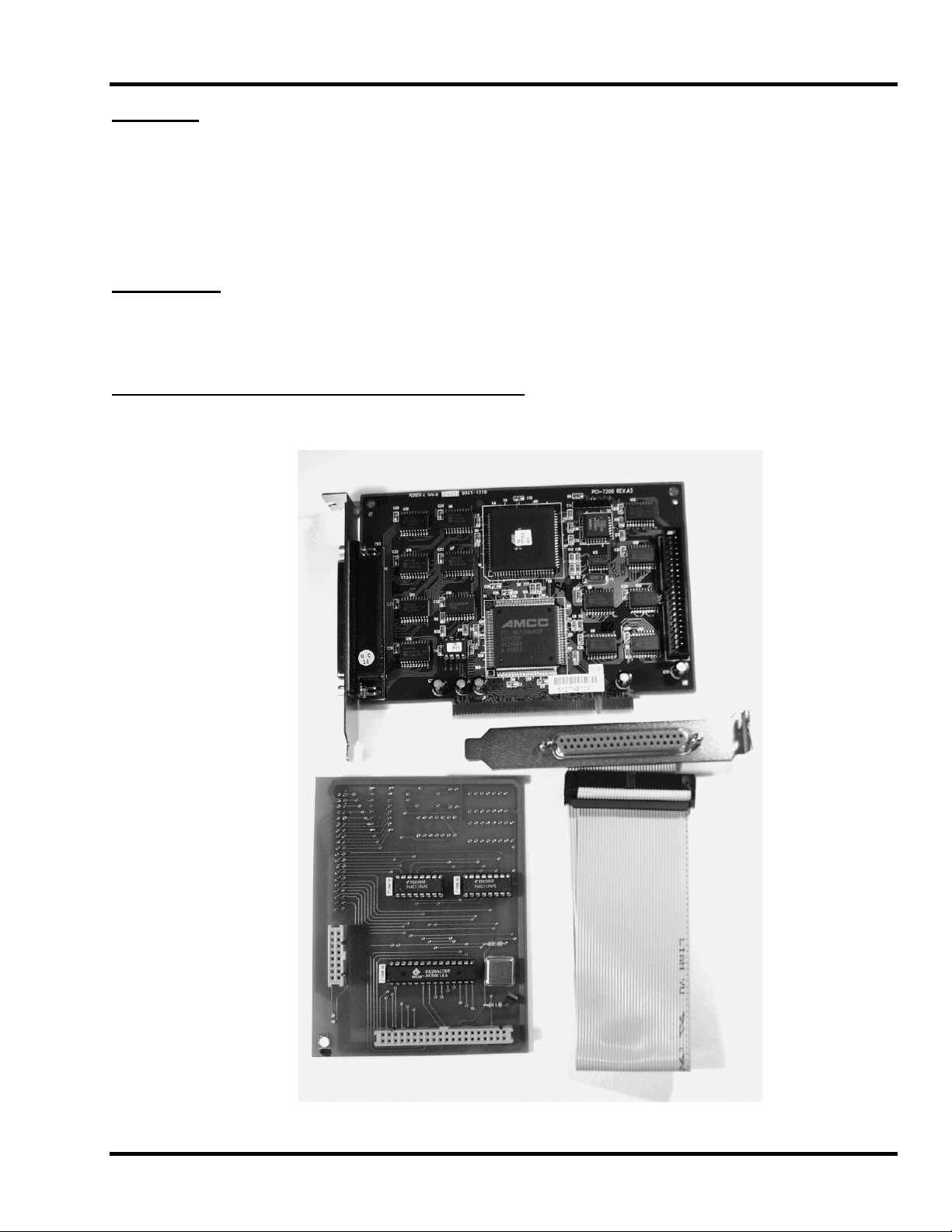
Installation and configuration of PCI-7200 card
Below are the components for the PCI-7200 installation. These include a PCI-7200 card, a Daughter Board, and
a ribbon cable connector.
WinCNC Users Guide 1 - 1
Page 4

WinCNC Controller Installation
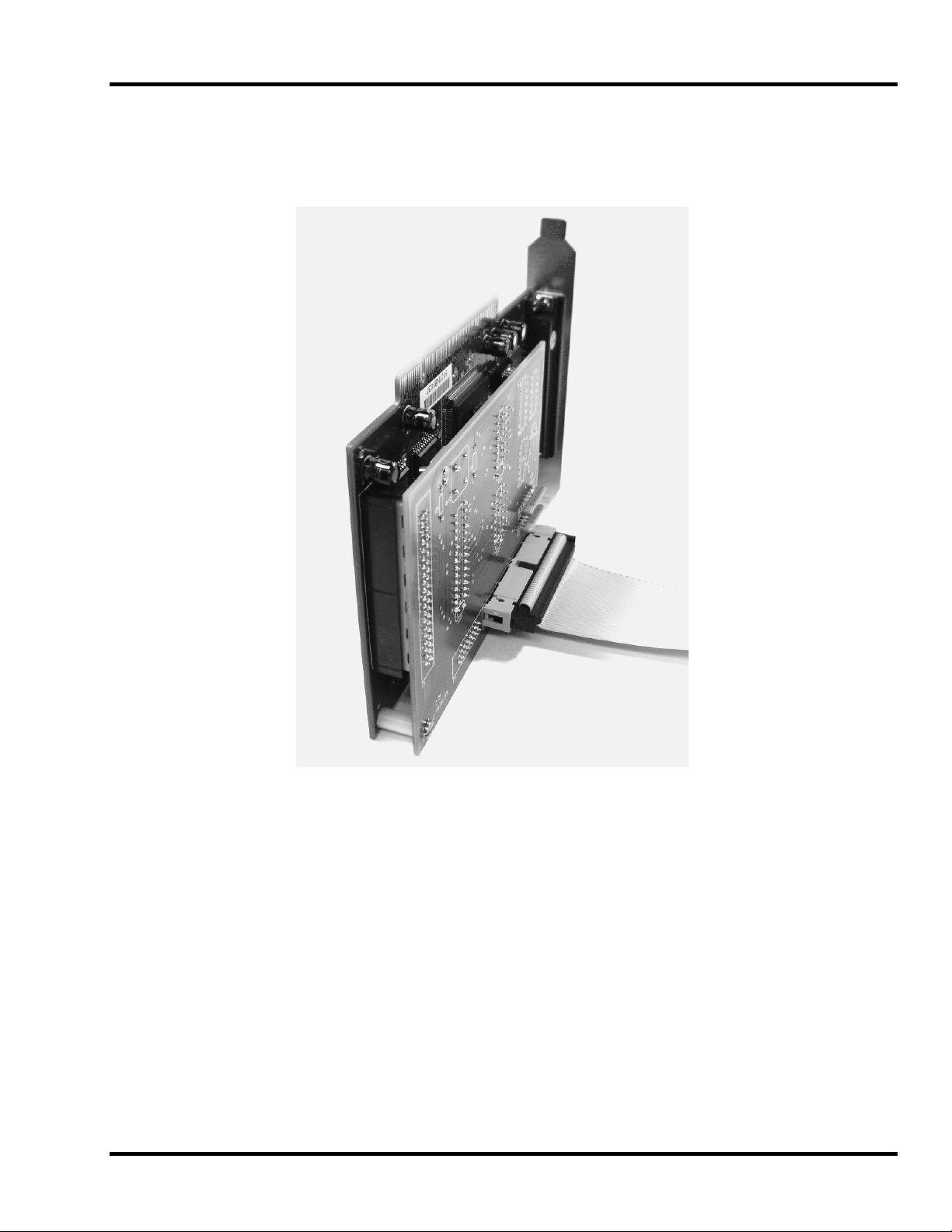
Insert the ribbon cable connector into the Daughter Board.
Below is the PCI-7200 card on the left, the Daughter Board on the right and the spacer/screw assembly.
Note the matching holes in the Daughter Board and the PCI-7200 card. The small washer is included for a
precise fit and must be installed between the boards, at one end of the spacer or the other.
WinCNC Users Guide 1 - 2
Page 5
WinCNC Controller Installation
Insert the Daughter Board on to the 40-pin connector of the PCI-7200 card. Attach the two cards with the
included spacer, washer and screws. This will insure constant connection between the two boards.
WinCNC Users Guide 1 - 3
Page 6

WinCNC Controller Installation
Power Down the PC.
Insert PCI-7200 card into an empty PCI slot on the motherboard. Install the extra 37-pin or 25-pin connector into
an empty cover slot.
Make sure the PCI-7200 card is using its own IRQ.
IRQ settings must be altered from the BIOS to insure no conflicts occur between the PCI-7200 card and other
system resources. Changing these settings from within Windows alone will not insure this.
A driver is required for the PCI-7200 card. The driver is included in a PCI-7200 folder on the root directory of the
CNC installation disk for user convenience, if the installation disk isn’t available, the driver can be downloaded
from the MicroSystems website. From the web, go to
bottom of the page. From there, open the “CNC Windows” folder, the “Device Manager” folder, and the
“PCI7200” folder. Download and unzip the driver file to a folder on your computer (we suggest that the folder be
placed on your Desktop).
To install the PCI-7200 driver go into the device manager (Start->Settings->Control Panel->System->Hardware>Device Manager) and select the unknown PCI device, click properties, click driver tab then click update driver.
Next specify location. If you are using the installation CD, browse to the CD, and then PCI-7200 folder. If you are
using the file from the FTP site, browse to the folder that you created.
www.cnccontroller.com, and click on the FTP link at the
Software Installation:
Insert the WinCNC Controller CD-ROM into the CD-ROM drive and run the Setup. The install routine will create
the specified directory if it does not exist and copy the necessary files into it. If there is a previous installation of
WinCNC controller the files will be overwritten. Run the program by double clicking the WinCNC icon on your
Windows desktop.
WinCNC Users Guide 1 - 4
Page 7
WinCNC Controller Screen Display
g
SCREEN DISPLAY:
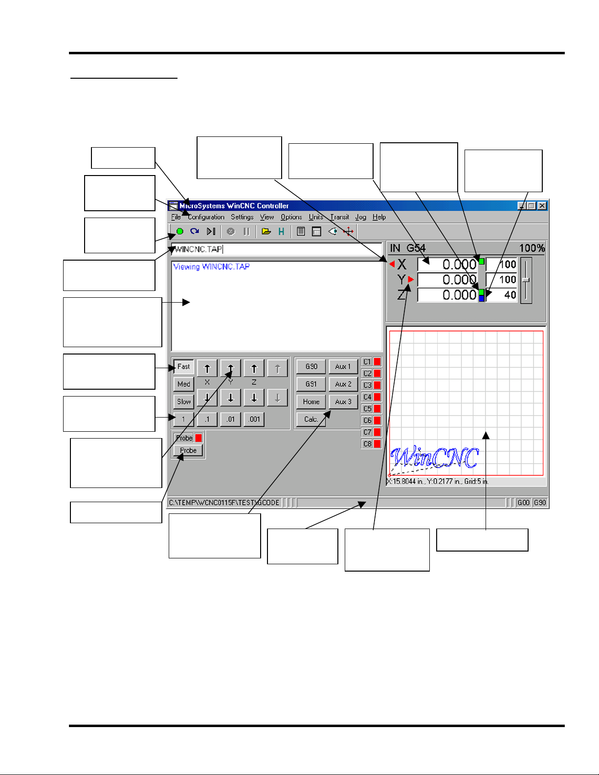
The following section contains a sample of the WinCnc software display. Common components are labeled to
provide clarity. Under the title of selected components is a reference to a page containing the detailed
explanation of the given component.
Title Bar
Menu Bar
See Page 2-2
Tool Bar
See Page 2-7
Command Line
See page 2-8
Message Display
Window
See Page 2-8
Transit Speeds
See Page 2-8
Jog Increments
See Page 2-9
Transit/Jog
Buttons
See Page 2-9
Probe Enable
Low Limit Switch
Hit Notification.
Red Triangle to Left
of Axis Label
Custom Screen
Buttons Section
See Page 2-9
Axis Window
See Page 2-8
Status Bar
See Page 2-9
Display to show
G92 is set for X
and Z.
Green Box
High Limit Switch
Hit Notification.
Red Triangle to
ht of Axis Label
Ri
Top
Display to show
Tool Measure set
for Z. Bottom
Blue Box
Viewer Window
WinCNC Users Guide 2 - 1
Page 8
WinCNC Controller Screen Display
SCREEN DISPLAY COMPONENT BREAKDOWN:
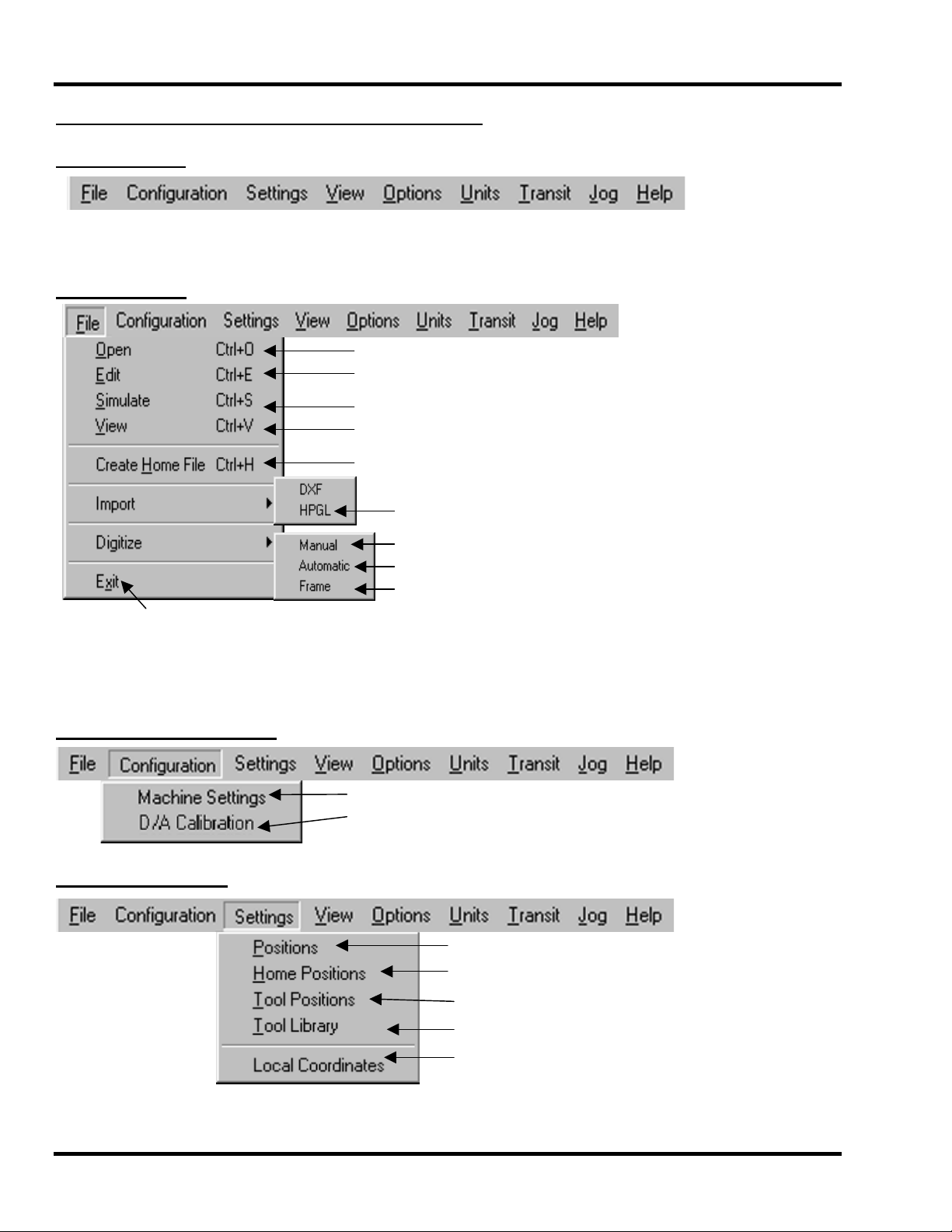
The Menu Bar:
The Menu Bar contains many of the main features of the WinCnc Software. It is broken down into several
generalized sections, as shown above. The following graphics display their options and uses under each section.
The File Menu:
*Note: You should only use the DXF and HPGL import feature of WinCNC for simple design. WinCNC does not
compensate for tool diameter when converting these files. For more complicated design, where intellegent tool
pathing is important, please use a compatible CAD/CAM program.
Quits
The Configuration Menu:
The Settings Menu:
WinCNC Users Guide 2 - 2
Opens a file
Opens the editor (if a filename is in the command line, editor opens that
file)
Simulates a file running to check for errors and time
Views a file in the viewer window
Creates a home file at the current machine position.
Allows the user to import DXF and HPGL files (* see Note)
Enable/Disable Manual Digitizing Toolbar
Automatic Digitizing (L802, L803)
Skeletal Digitizing (Uses L810)
Starts the WinCnc Ini File Editor
Calibration Settings for D/A
Views Positions
iews Home Positions
V
Views Tool Positions
Views Defined Tool Library
View XYZ Coordinates
Page 9
WinCNC Controller Screen Display
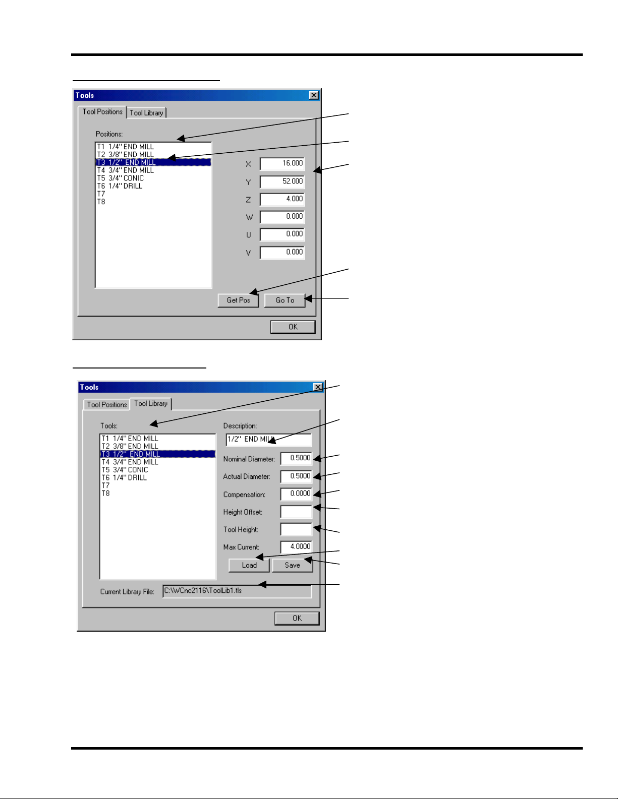
The Tool Positions Menu:
The Tool Library Menu:
Stored Tool Position list.
Currently selected Tool.
Machine Position of currently selected Tool
in Tool Holder.
Stores the current machine position. Should
be clicked when Tool is squarely in Tool
Holder.
Moves to the position of selected tool.
Current Tool Library.
Currently selected Tool.
Diameter this bit should be.
Actual diameter of this bit.
Amount toolpath must be shifted to
compensate for difference.
Distance, positive or negative, to
compensate for specialized Tool.
Distance head must travel from absolute
zero in order for Tool to touch the table.
Load a Tool Library.
Save a Tool Library
Current Library file and path.
WinCNC Users Guide 2 - 3
Page 10

WinCNC Controller Screen Display
The Home Positions Menu:
The Positions Menu:
Programmable Home Positions List
Selected Home Position (name optional)
Clearance after Z height adjustment
Axis positions for this Home Position.
WinCNC sets a G92.1 for these positions.
Stores these axis coordinates as a new
Home Position.
Moves to selected Home Position and sets
local zeros.
Programmable Positions List
Selected Position (name optional)
If G92 is set, “Local” moves machine relative
to G92 setting. Absolute moves machine to
coordinates specified regardless of G92
settings.
Axis coordinates for this stored Position.
Stores these coordinates as a Position.
Moves to selected Position.
WinCNC Users Guide 2 - 4
Page 11

WinCNC Controller Screen Display
The View Menu:
The Options Menu:
The Units Menu:
Sets units of measurement to Inches
Sets units of measurement to Centimeters
Sets units of measurement to Millimeters
The Transit Menu:
Sets Transit speed to Slow
Sets Transit speed to Medium
Sets Transit speed to Fast
View current Resolution settings for each axis
View current Acceleration settings for each axis
View current Limit settings for each axis
Views current input states (will also change in state)
Enable/Disable the Main Toolbar.
Refreshes the screen
Clears the message display window
Enable/Disable the Soft Limits Option
Enable/Disable the Keyboard Transit/Jog
Control
Used to Customize User Buttons
Auto populate the command line with last
command
Enables/Disables the Auto run feature
Enables/Disables the Auto preview feature
Enables/Disables single line execution of
G-Code files.
WinCNC Users Guide 2 - 5
Page 12

WinCNC Controller Screen Display
The Jog Menu:
The Help Menu:
The About box in the WinCnc Controller software contains important information about your specific software
package. The About Box displays your security key serial number, the software version number, your user level,
the maximum number of axis, the table size limitation, and which additional features you have enabled. If you do
not have a feature enable that you would like or need, you can contact your software vendor for an upgrade.
Sets Jog Increment to 0.001
Sets Jog Increment to 0.01
Sets Jog Increment to 0.1
Sets Jog Increment to 1
Sets Jog Increment to Custom
Activates the in Program help menu
Opens the Updating Utility
Opens the WinCnc About window
WinCNC Users Guide 2 - 6
Page 13
WinCNC Controller Screen Display
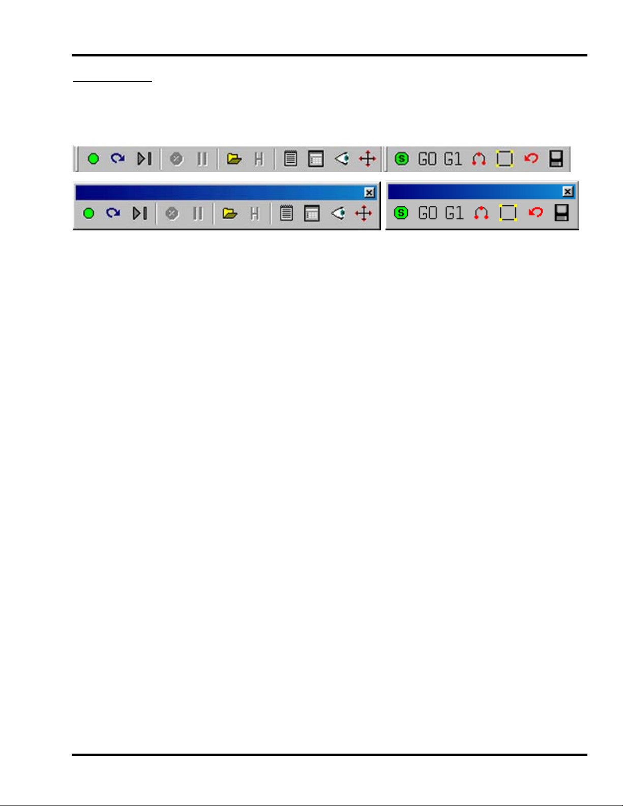
The Tool Bar:
The tool bar is a collection of shortcut buttons that perform specific actions. The Toolbars in WinCnc are floating
and can be positioned or docked to the user’s preference. The image below shows both the standard and manual
digitizing toolbars both docked in the normal toolbar area. The additional images show each toolbar separately as
a floating toolbar. The explanation of each button on the toolbar is as follows. The explanations move
sequentially from left to right along the toolbar.
Start Motion: This button will begin the command or job listed in the command line.
Restart: Allows you to pick a job file and the line to start that file on. This is useful if you want to skip over lines in
a job file, or if you have aborted a job and want to start back at the point you aborted from. You can also choose
to run the file in single step mode.
Single Step: When selected, this allows you to execute one line of a G-Code file each time you hit ENTER.
Abort Motion: Aborts a command or job that is running.
Pause/Continue Motion: Pauses/Continues a command or job that is running.
Open File: Opens a browse box that is used to open a job file.
View Hi story: Opens the command history box, which allows a user to execute a command used previously.
When an error is found in the WinCnc.ini file, the line containing the syntax error is displayed here in red when
WinCnc starts.
Edit: Opens the default editor specified in the WinCnc.ini file. WinCnc uses notepad by default. The editor can be
used to open job files, listed in the command line, in the editor.
Simulate: Simulates a file to check for errors and run-time
View: Opens a file for viewing in the viewer window
Soft Limits: Enables/Disables Softlimit features
Manual Digitize Buttons: The seven buttons on the manual digitization toolbar are for use only with the Manual
Digitize feature, and will only be visible after showing the manual digitize toolbar under the View->toolbars section
of the menu bar.
Start a Manual Digitized File: Starts a manual digitized file and enables the manual digitize mode.
Add a Rapid Move: Adds a rapid move to the manual digitized file.
Add a Feed Move: Adds a feed move to the manual digitized file.
Add an Arc Point: Used to add arcs into a manual digitized file.
Close Shape: Used to close the last move in a shape without moving the machine.
Undo: Used to undo previous moves.
Save: Allows you save the manual digitized file in either G-Code or DXF file format.
WinCNC Users Guide 2 - 7
Page 14
WinCNC Controller Screen Display
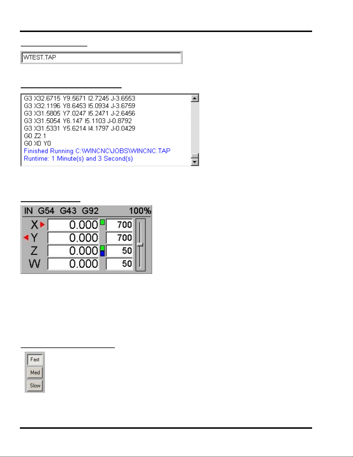
The Command Line:
Is the Input line for users to enter commands or job files to be executed.
The Message Display Window:
The message display window is the main output window displaying the commands that have been executed,
messages to the user, or errors that have occurred during an operation.
The Axis Window:
The axis window is the primary display for current information about each axis on your machine. The current
positions and velocities for each axis are displayed in the text boxes. Displayed above the position and velocity
boxes are the current units of measure, any currently active modes, and the current feed rate override
percentage. Red triangles to the left and right of each axis label indicate low or high limit switch hits. A red
triangle to the left of an axis label indicates a low limit switch hit, and to the right indicates a high limit switch hit. A
green box displayed to the right of the position box indicates a temporary workspace setting, and a blue box
indicates a tool length measure setting. To the far right side of the axis window is the feed rate override control
slide bar.
The Transit Speeds Buttons:
These buttons allow you to specify the transit speed of your machine.
WinCNC Users Guide 2 - 8
Page 15

WinCNC Controller Screen Display
The Jog Increment Buttons:
These buttons allow you to spe
cify the increment of a jog move.
he Transit/Jog Buttons:
T
what allow you to initiate a manual transit or jog movement from the console of the computer These buttons are
that runs the machine. In transit mode, holding the button down will continuously move the machine. In jog
mode, each time a button is pressed the machine will move according to the jog increment that has been
selected. Holding the button down in jog mode will move the machine only once.
The Custom Screen Buttons Section:
This section of controls is a customizable button section that allows the user to place shortcut buttons to activate
heavily used commands.
ote: See Section 4 Screen Configuration
N
he Status Bar:
T
label along the bottom of the WinCnc window that looks similar to the one shown below. The status bar is the
This bar provides the user with the status of several features in WinCnc. Each section in the example below is
labeled for clarity.
Curre
nt
Line in Job
F
ile
Elapsed Time for
Current File
G00/G01
Mode
Indicator
Current File
Percentage of
File Completion
Tool Changer ON/OFF
and current tool being
used
* Note: There are TWO
tool changer indicators
G90/G91
Mode
Indicator
WinCNC Users Guide 2 - 9
Page 16
WinCNC Controller Screen Display
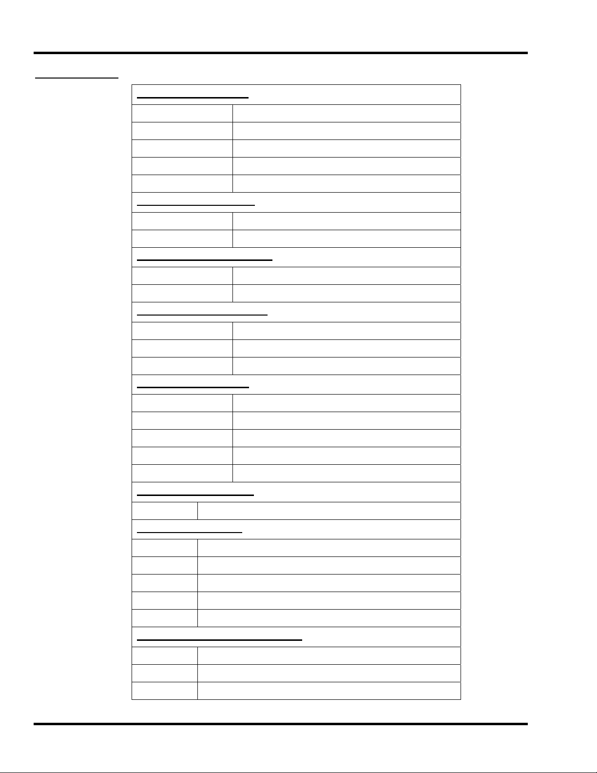
Shortcut Keys:
File Menu Shortcuts
Ente
Open
r(only when command line is blank), (Ctrl+0)
Edit
Simulate
View
Create Home File
(Ctrl+E)
(Ctrl+S)
(Ctrl+V)
(Ctrl+H).
View Menu Shortcuts
Refresh View
Clear Messages
(F5)
(Ctrl+
C)
Options Menu Shortcuts
Keyboard
Soft Limit
(Ctrl+K).
(Ctrl+L)
Transit Menu Shortcuts
Slow
Medium
Fast
(F2).
(F3)
(F4)
Jog Menu Shortcuts
(F6)
.001
.01
.1
1
Custom
(F7)
(F8)
(F9)
(F10)
Help Menu Shortcuts
Help
(F1)
Tool Bar Shortcuts
ESC
SPACE
ENTER
TAB
Ctrl+R
Aborts the
Pauses a file or command.
Starts/restarts a file or command.
Opens the command history box.
Opens the restart file box.
current file or command.
Feed Rate Override Shortcuts
Insert
Delete
Ctrl+either
Increases override rate
Decreases override rate
Resets feed rate to 100%.
No override settings
WinCNC Users Guide 2 - 10
Page 17

WinCNC Controller Screen Display
Shortcut Keys cont.:
Manual Digitize Shortcuts
olbar and clicking the green start button the following shortcut key After opening the Manual Digitize to
combinations become active for adding moves to the digitized file.
Add Rapid Move
CTRL+J
Add Feed Move
Add Arc Midpoint/Endpoint
Undo Last Move
Close Current Shape
Save
CTRL+F
CTRL+A
CTRL+U
CTRL+D
CTRL+W
Spindle Speed and Laser Power Shortcuts:
Spindle Speed Alone or
Laser Power Alone
Spindle Speed and
Laser Power Together
+ – (plus and minus)
Laser Power uses + - (plus and minus)
Spindle Speed uses Shift + - (shift, plus
and minus)
WinCNC Users Guide 2 - 11
Page 18

WinCNC Controller System Configuration
System Configuration:
WINCNC.INI is read on program startup. The preconfigured file is setup to work with minimal change for normal
installations. To change configuration use a text editor to edit WINCNC.INI. If the WINCNC.INI is changed while
WinCNC is running you must restart the program to activate your changes.
CAUTION!!
Make sure you have some idea of what you are doing before changing WINCNC.INI. All input and output is
controlled by these settings. Improper settings will cause limit switches to not work, wrong axis movement in the
wrong directions, and/or other bad and potentially dangerous or damaging incorrect operation.
Please call for help instead of experimenting if you are not very familiar with motion control concepts and
computer configuration.
Use a text editor (such as EDIT.COM or NOTEPAD.EXE) to edit WINCNC.INI. Change values for parameters as
specified below. WINCNC.INI is read every time the program is started. Make sure the file gets saved as ASCII
text (without formatting).
WINCNC.INI Settings:
Unit Settings:
The default unit of measure is inches. If you want to use this WINCNC.INI setting to set the unit of measure, it
must be the first line in the ini file. No other line matters in placement except the Unit= line. You can also set
units by choosing Units from the menu bar and selecting the desired unit of measure.
Unit= (unit) (Unit) is the unit of measurement you want to use.
IN – sets unit= to Inches
CM – sets unit= to Centimeters
MM – sets unit= to Millimeters
Example: unit=IN would set up your configuration to use Inches as
the unit of measurement.
Many WINCNC.INI settings are similar except for the axis specifier, the port number, etc. In this case the
reference below will specify the parameter to be changed in <>. For example:
Timer Card Setup:
Timertype=<#> # Must be 7200.
Maxstepv=<#> # is the maximum number of pulses per second per axis. The default
value is 30000, and can safely be increased to 50000 when using the
2801 or 7200 timer type.
Accel=S<#> S<#>sets the max velocity increment during acceleration. Can be 0
to 50000. The default value is 50.
WinCNC Users Guide 3 - 1
Page 19

WinCNC Controller System Configuration
Port Settings:
NOTE: See the Appendix for the default port settings.
Portin=<#, *> # is the number of the port, can be 0-7. * is the hexadecimal memory
address to the port.
Portout=<#, *> # is the number of the port, can be 0-7. * is the hexadecimal memory
address to the port.
Comment characters:
Comchars=<###> ### represents characters to use to designate comments in a GCode
file. When one of the listed characters is found at the beginning of a
line, WinCnc skips the entire line. The characters “[(%” are regarded
as comments by WinCnc by default. Warning: Any character listed
here will be considered as a comment character, therefore
everything that follows that character on any line will be ignored.
Override Settings:
Gives the user the options of enabling of disabling the feed rate override, and setting the low and high limitations
for the feed rate.
Override=E# L# H#
Pause/Abort from any unassigned keyboard key:
By default, the Spacebar is the Pause key and the Escape key is the abort key. By including the anykey= line in
the WinCNC.INI file, the user can set WinCNC to read any unassigned key as a pause key or an abort key.
Anykey=A#P# A# enables or disables abort on any unassigned key. 0 is disabled, 1
E# enables or disables the feed rate override. Can be set to 0 or 1. 0
is disabled, 1 is enabled. The default is enabled. L# sets the lower
limitation of the override percentage. Can be 1 to 200, but must be
lower than the high value. H# sets the high limitation for the override
percentage. Can be 1 to 200, but must be higher than the low value.
is enabled.
P# enables or disables pause on any unassigned key. 0 is disabled, 1
is enabled.
If both a1 and p1 are included, any unmapped key will be read as an
abort.
WinCNC Users Guide 3 - 2
Page 20
WinCNC Controller System Configuration
Axis Settings:
Axischar=<###> # is desired alpha axis label. Example: axischar=XYZ
Axisspec=P<#>S<#>D<#>R<#>
A<#>O<#>E<#>T<#>B<#>K<#>
Altaxisspec=P<#>S<#>D<#>O<#>
E<#>
Axisvel=R<#>F<#>S<#>M<#>H<#>
A<#>C<#>
Backlash=B<#>S<#>F<#> B# sets initial backlash compensation to on or off, can be 0 or 1.
[SEE DIAGRAMS IN APPENDIX]
P# is port number.
S# is the bit for the step signal, can be 0-7.
D# is the bit for the direction signal, can be 0-7.
R# is the actual resolution in steps per unit.
A# is the actual acceleration in units per minute per second.
O# changes motor direction, can be 0 or 1.
E# sets the step signal for negative edge triggered drives, can be 0 or 1.
E0 is default, a negative going pulse, E1 is positive going.
T# sets the type of axis. 1 is first horizontal. 2 is second horizontal. 3 is
vertical. 4 is rotational.
B# is the amount of backlash to compensate for on this axis.
K# is used for keyboard mapping to this axis.
Ignores Scroll Lock
1 Left/Right Arrow Keys
2 Up/Down Arrow Keys
3 PageUp/PageDown Keys
4 Home/End Keys
Works Only with Scroll Lock Off
5 Left/Right Arrow Keys
6 Up/Down Arrow Keys
7 PageUp/PageDown Keys
8 Home/End Keys
Works Only with Scroll Lock On
9 Left/Right Arrow Keys
10 Up/Down Arrow Keys
11 PageUp/PageDown Keys
12 Home/End Keys
See Axisspec= documentation on the previous page. This setting is
used for an axis that has two motors, and specifies the step and
direction settings for the second motor. Uses the same resolution,
acceleration, type, and backlash as axis specified in the previous
Axisspec= line
NOTE: axisvel is associated with the preceding axisspec line.
R# sets the rapid or G0 velocity for the axis.
F# sets the feed or G1 velocity for the axis.
S# sets the velocity for slow transit.
M# sets the velocity for medium transit.
H# sets the velocity for fast transit.
A# specifies an acceleration factor for transit moves.
C# sets minimum velocity used in velocity matching. Using this setting
improves smoothing and reduces cutting times.
S# sets the smoothing factor for backlash compensation moves.
F# sets the “slow down” feed rate setting to eliminate “clicking” during
arc backlash compensation moves. Example: backlash=b1 f100 means
enable backlash, slowdown feedrate of 100 units per minute.
WinCNC Users Guide 3 - 3
Page 21

WinCNC Controller System Configuration
Vgroup=<F><###> F is only used for the feedrate command group. It normally locks the X
and Y axes together. It isn’t used on any other vgroup line.
#’s are the desired alpha axis labels to group velocity.
Examples:
Vgroup=FXY is the special feedrate command group; If the command
F300 is given on the command line, it forces the X and Y axes to use
300 as their feedrate.
Vgroup=XY would lock the X and Y axes, so that if the command G1
X15 F50 is entered, both axes would be set to 50. Otherwise, Y would
remain at whatever feedrate it had previously been set to.
Other than the X and Y axes, each axis should have its own vgroup; i.e.
Vgroup=Z.
Axismode=A<#>V<#> NOTE: axismode is associated with the preceding axisspec line.
A# is the acceleration factor to use for smoothing on this axis.
V# is the increment used during acceleration in steps/second.
Steppulse=P<#>D<#> P# is the length of each step pulse in microseconds.
D# is the amount of time before each step that the direction signal is set.
NOTE: These settings default to 5, and are generally unused.
Axislo and Axishi:
Are used if the channel specs are not used in the preceding Axisspec or if the limit switch is non-standard for
channel specs.
Axislo=P<#>B<#>O<#>A<#> P# is the input port for limit switch, can be 0-3.
B# is the bit on the port used with the switch, can be 0-7.
O# sets the switch polarity, can be 0 or 1.
A# sets the alternate bit.
Axislo=P0 B2 A4 [bit 2, alternate bit 4]
Altaxislo=P<#>B<#>O<#>A<#> Low limit for Altaxis. See Axislo= documentation above.
Axishi=P<#>B<#>O<#>A<#> P# is the input port for limit switch, can be 0-3.
B# is the bit on the port used with the switch, can be 0-7.
O# sets the switch polarity, can be 0 or 1.
A# sets the alternate bit.
Axishi=P0 B0 A1 [bit 0, alternate bit 1]
Altaxishi=P<#>B<#>O<#>A<#> High limit for Altaxis. See Axishi= documentation above.
Limit Switches:
The default channel settings will normally provide proper interfacing with the machine’s limit switches. Before
attempting to move the machine verify that all limit switches are functioning properly. Limit switch status is
displayed in the position window using a red triangular indicator to the left or right of the axis label. The indicator
to the left of the axis label shows low limit status for that axis, the indicator to the right of the label shows high limit
status. If the indicator is present then the limit switch is closed otherwise it is open.
The lim_mode setting is used to control how WinCnc responds to limit switch triggers.
WinCNC Users Guide 3 - 4
Page 22

WinCNC Controller System Configuration
Lim_mode=<#> # can be one of the following:
0 = same debounce for on and off, any limit switch causes an abort.
1 = same debounce for on and off, only limit switch in the direction of
motion causes an abort.
2 = less debounce for change to off, any limit switch causes an abort.
3 = less debounce for change to off, only limit switch in the direction of
motion causes an abort.
Lim_cnt=<#> # sets the debounce for limit switches.
First toggle your limit switches by hand. Verify that the appropriate limit display toggles. If it does not toggle then
you need to adjust WINCNC.INI. See the WINCNC.INI reference sections of the manual if the default settings are
incorrect for your machine.
It is recommended that you verify limit switch operation at the beginning of each session. Do not attempt
movement until the limit switch displays toggle correctly. Once the limits are working try a small move. If nothing
moves, the wrong axis moves, or movement is in the wrong direction then adjust WINCNC.INI.
Perhaps the easiest way to do preliminary testing of movement is with the Jog mode. Select Jog .1”, and select
the KEYBOARD option under the OPTIONS menu. If you are using the default jog key configuration, use the
LEFT and RIGHT arrow keys to move X, the UP and DOWN arrows to move Y, the PAGEUP and PAGEDOWN
keys to move Z and U, and the HOME and END keys. Otherwise use the buttons that are defined for your
system.
Auxout, Autoaux, and Auxin:
Auxout=C<#>P<#>B<#>O<#>S<#>
E<#>T<#>X<#>W<#> T<#>
[SEE DIAGRAMS IN APPENDIX]
AuxOutVel=# # is the velocity percentage to use (0-100). If the machine velocity,
C# is the channel number, 1-32. Numbers should not be skipped.
P# is the port number, refers to a port specified in a portout spec.
B# is the bit number, can be 0-7.
O# changes the output polarity, can be 0 or 1.
S# set output state on WinCnc startup, can be 0 or 1.
e# set output state on WinCnc exit, can be 0 or 1.
X# set output state on abort, can be 0 or 1.
W# set output state on pause, can be 0 or 1.
T# sets the type of auxout. # can be 2 or 3. T2 sets the auxout
channel to be a motion only auxout. This will result in the auxout only
working while the machine is moving and will turn off when the
machine stops. To use this feature you must also have the S# set to
1 to start up with the software. You can then change it off and on
using the M11 and M12 commands. You must have it enabled to
work correctly during motion. The T2 setting only works with a PCI
card, it does not work with an ISA card or a parallel port connection.
T3 sets the auxout to a programmed velocity percentage auxout type.
during motion, drops below the specified percentage of the
programmed velocity then the auxout signal will be on, otherwise the
auxout signal will be off.
WinCNC Users Guide 3 - 5
Page 23

WinCNC Controller System Configuration
Autoaux=C<#>I<#>S<#>E<#>
Auxin=C<#>P<#>B<#>O<#>D<#>
F<#> M<”error message”>
[SEE DIAGRAMS IN APPENDIX]
C# is the auxiliary output channel number
I# is the initial state of the AutoAuxOut mode (0=off, 1=on).
S# sets the amount of dwell time in seconds used when the
AutoAuxOut channel is set to on.
E# sets the amount of dwell time in seconds used when the
AutoAuxOut channel is set to off.
This feature allows the user to setup an auxiliary output that will turn
on during G1/G2/G3 moves, and will turn off for all other moves, only
if the “AutoAuxOut” mode is set to on. The “AutoAuxOut” mode can
be enabled using the L34 command and disabled using the L35
command.
C# is the channel number, 1-32. Numbers should not be skipped.
P# is the port number, refers to a port specified in a portin spec.
B# is the bit number, can be 0-7.
O# changes the input polarity, can be 0 or 1.
D# specifies debounce. When the input is a switch, debounce should
be used. D100 is a typical value.
F# specifies the function type of the auxin. Can be set to the same
function types as enab, or signal below. When sets to 0, no special
function types are enabled.
M<error message> denotes a custom error message. The me ssage
must be enclosed in double quotes – “”.
Watchdog:
The “watch” feature in WinCnc generates a square wave using an Aux-Out channel, timer chip out 0, or timer chip
out 1.
Watch=T# D# C#
Examples:
Watch=T1 Timer Out 0 (Startup=Low, Exit=High)
Watch=T2 Timer Out 1 (Startup=Low, Exit=High)
Watch=T3 Timer Out 0 and Timer Out 1 (Startup=Low, Exit=High)
Watch=T4 D50 Timer Out 0 (50 ms Square Wave)
Watch=T5 D50 Timer Out 1 (50 ms Square Wave)
Watch=T6 D20 Timer Out 0 and Timer Out 1 (20 ms Square Wave)
Watch=T7 C1 D20 Aux-Out Channel 1 (20 ms Square Wave)
T# is type (1-7)
D# is delay
C# is aux-out channel number
T# can be 0 for pin 11, 1 for pin 15, or 3 for both
The feature can only be enabled if the “pumpcont” feature is not
used. Output pins 11 and 15 will go high when the PC is powered up.
When the “watch” feature is enabled, one or both of these outputs will
go low while WinCnc is running and high again when WinCnc exits.
WinCNC Users Guide 3 - 6
Page 24

WinCNC Controller System Configuration
Signal:
Is used to setup control pushbuttons. First setup an auxin line for the input. Then specify signal as follows to use the input channel as a control signal.
Signal=C<#>M<”error message”> T<#> C# specifies the input channel to be used for the signal.
C<error message> denotes a custom error message. The
message must be enclosed in double quotes – “”.
T# specifies the signal type.
*100 Abort
*101 Pause/Continue
*102 Pause
*103 Continue
*110 Start Cycle
*201 Run command stored with L201 command
*202 Run command stored with L202 command
Enable:
Is used to setup emergency stops. First setup an auxin line for input. Then specify the enable as follows to use
the input channel as an enable switch.
Enab=C<#>C<”error message”>T<#> C# specifies the input channel to be used for the enable.
M<error message> denotes a custom error message. The
message must be enclosed in double quotes – “ “.
T# auxin enable type. 1 is default and will abort from any
command when the enable switch is triggered. 2 will abort only
from commands that would result in machine motion when the
enable switch is triggered.
Abort Cushions:
Lim_step=<#> # is the number of steps to compress limits after switch hit.
Esc_step=<#> # is the number of steps to move after ESC key pushed.
Some machines may be damaged if stopped suddenly at higher speeds. Abort cushions provide a method of
decelerating quickly but not instantly when a limit is hit or the escape button is pushed.
Lim_step specifies the number of steps to continue after a limit is hit. This number must be calculated from the
distance your switches may be compressed without damage and the lowest axis resolution of your machin e.
For instance if your X and Y resolution are 1018.592, your Z and W resolution are 2000 and your limit switches
may be compressed .1” then you would set lim_step as follows:
Lim_step=1018.592*.1=100 steps
Esc_step may be set to any value that results in a quick stop without moving too far. A 200 setting is suggested.
G28 Settings:
G28move=X<#>Y<#>Z<#>E<#>R<#>
T<#> A<#>M<#>F<#>
G28altmove=X<#>Y<#>Z<#>W<#> Used to square a machine with two motors on the gantry.
G28coord=X<#>Y<#>Z<#>W<#> Specifies a position after a G28, not used if all positions are zero.
G37 Settings:
G37=X<#>Y<#>D<#>F<#> X# is the X position of the tool measure switch.
Y# is the Y position of the tool measure switch.
D# is the rapid decent distance.
F# is the feed rate for the remaining decent distance after rapid rate.
WinCNC Users Guide 3 - 7
XYZW specifies the distance to move from each limit switch while
homing. The R specifies the distance to move off the limit switch
after the first contact. F is the approach speed to use for the initial
contact. T is the approach speed to use to for second contact. A is
used to specify that an alternate limit switch is to be used. M
specifies that each axis will home individually.
Page 25

WinCNC Controller System Configuration
Soft Limits:
Lolim=X<#>Y<#>Z<#>W<#> X# is the low soft limit value for X.
Y# is the low soft limit value for Y.
Z# is the low soft limit value for Z.
W# is the low soft limit value for W.
Hilim=X<#>Y<#>Z<#>W<#> X# is the high soft limit value for X.
Y# is the high soft limit value for Y.
Z# is the high soft limit value for Z.
W# is the high soft limit value for W.
Lobound=X<#>Y<#>Z<#>W<#> X# is the low boundary value for X.
Y# is the low boundary value for Y.
Z# is the low boundary value for Z.
W# is the low boundary value for W.
Hibound=X<#>Y<#>Z<#>W<#> X# is the high boundary value for X.
Y# is the high boundary value for Y.
Z# is the high boundary value for Z.
W# is the high boundary value for W.
Softlim=T<#>M<#> T# can be one of the following. 0=disable 1=enabled and active
2=enabled but inactive.
M# is to tell whether or not to show the softlim’s toolbar icon. 1 will result
in the toolbar icon being shown, 0 for not shown. Boundaries and Soft
limits are linked, so the state of 1 represents the state of the other. So the
boundary= line is not needed.
Arc Settings:
Arc_err=<#> # Is the value (in units of measure) of allowable errors in arc
specifications.
Default value is .01. If you get radius errors from your files increase in .002 steps. If errors persist with larger
values the problem is probably in your program.
Arc Radius errors indicate that the distance from the start point to the center point is not the same as the distance
from the end point to the center point.
Arc_min=<#> # is the value (in units of measure) for smallest arc radius to be cut as an
arc. Arcs with radius smaller than this value will be cut as a G1 move.
Default value is .002.
Arc_tol=<#> # is the value (in steps) for full circle. If the distance from the start point to
the end point (in steps) is less than arc_tol then a full circle will be cut.
Default value is 3 steps.
Arcfeed=<#> # can be 0 for Auto Mode or the velocity desired.
Arc_feed_lock=<#> # can be one of the following values. 0, 1, or 2 as above.
G2modal=<#> # can be 0 or 1, if 0 G2 and G3 commands are non-modal, if 1 G2 and
G3 commands are modal. The default is non-modal.
Arc Feed rates may be set to Automatic Mode or set to an initial rate. In Automatic Mode arcs are run at the
current XY feed velocity unless the radius is too small to support that velocity, in which case the maximum arc
velocity is calculated based on the acceleration settings for the X and Y axis’s. Arc Feed rate may also be locked
as above. Smoothest motion is usually obtained using Auto Mode.
Rapidjog Settings:
Rapidjog=<#> # can be 0 or 1. If 0, jog moves use G1 speed (this is the default). If set
to 1, jog moves use G0 speed.
WinCNC Users Guide 3 - 8
Page 26

WinCNC Controller System Configuration
Workspace:
G54=X<#>Y<#>T<#>A<#>R<#>
O<#>
G55=X<#>Y<#>T<#>A<#>R<#>
O<#>
G56=X<#>Y<#>T<#>A<#>R<#>
O<#>
G57=X<#>Y<#>T<#>A<#>R<#>
O<#>
G81 Settings:
G81dwell=<#> # is the value (in seconds) of the desired dwell at the end of the plunge
Laser Settings:
Laser=P<#>D<#> P# is the initial power scale.
D/A Settings:
Da=T<#>A<#>V<#>I<#> T# is the type of D/A port used. Can be 0 (parallel port) or 1 (PCI
Tool Changer Settings:
X# is the workspace shift value for the X axis.
Y# is the workspace shift value for the Y axis
T# is the type of workspace shift. Use 0 for vertical head swapping and
use 1 for rotational axis
A# is the axis number. This setting is used only for type 1.
R# is the radius, which is used for type 1’s which have an off center bit
O# is the offset value, which is used for correcting the 0 degrees
position. The 0 degrees position should point toward the positive X
direction
move. The default value is 0.
D# is the laser power duty cycle.
daughter board).
A# is the parallel port address and is only used when t is set to 0.
V# is the maximum voltage - generally 5 or 10 volts.
I# is the value to which you wish the port to be initialized when WinCNC
starts. It can be set from 0 to the maximum set in V#.
Atc1=H<#>O<#>Z<#>A<#>L<#>
N<#>M1
Atc2=H<#>O<#>Z<#>A<#>L<#>
N<#>M1
SST Servo Drive:
Sst= C# R# V# C# is the COM port number being used.
Sstnode=A#D# A# sets the axis number for this node (servo drive). 0=X, 1=Y, 2=Z, ….
Add a “SSTNODE=” line for each servo drive on the serial loop. If there is a drive connected for which you DO
NOT wish to change resolution specify “D0”
H# is the height at which the tool is unloaded.
O# is the offset to the tool sensor.
Z# is height of the bottom of the tool changing spindle.
A# is the axis number for the tool changing spindle. X=0, Y=1, etc.
L# is the lowest tool number.
N# is the total number of tools in the spindle
M1 allows the use of the new library option.
R# sets the division for resolution when switched to rapid mode. Can
be 2,4,6, or 8.
V# sets if each command sent to a servo drive is validated. 0=not
validated, 1=validated (default).
D# sets the division for this node (servo drive). Can be 0, 2, 4, 6, or 8.
WinCNC Users Guide 3 - 9
Page 27

WinCNC Controller System Configuration
Pump Control Settings:
Pumpcont=T<#>L<#>H<#>A<#>
B<#>I<#>R<#>
KeyPad Settings:
Keypad=C<#>B<#>P<#> C# is the number of the com port used with the keypad.
Keypaddir=c:\wincnc\keypad Specifies the directory where file that can be ran from the keypad type
AutoRun Settings:
T# sets the pump control type. The available types are:
T0 pulse width
T1 pulse width with auto reverse.
T2 pulse width without auto reverse, double scaled.
T3 frequency mode.
L# sets the low value of the output range in units per minute.
H# sets the high value of the output range in units per minute.
A# sets the low value of the frequency range in pulses per second.
B# sets the high value of the frequency range in pulses per second.
I# is the initial value of the pump control output. (0-99)
R# is the initial value of the pump reverse output. (0-15)
B# is the baud rate used with the specified port. Should be 9600.
P# is the type of keypad used. Type 1 is the standard serial keypad,
type 2 is the Q-Term brand keypad with LCD display, and type 3 is the
2Tech brand keypad with LCD display and optional emergency stop.
2 will be stored.
Autodir=c:\wincnc\auto Specifies the directory where files to be automatically ran are copied.
Autofdir=c:\wincnc\done Specifies the directory where files are copied after auto run.
Automode=<#> The autorun mode 0 is disabled, mode 1 will copy name and path to
command bar, mode 2 will automatically execute the found file.
Log File Settings:
Logdir=c:\wincnc\log Specifies the directory where the log file is written.
Logfile=c:\wcnc.csv Specifies the name of the log file.
Home File Settings:
Homedir=c:\wincnc\homes Specifies the directory where created home files are written.
Bitmap Button File Settings:
Bitmapdir=c:\wincnc\bitmaps Specifies the directory where bitmaps used with the splash screen and
screen buttons are kept.
Editor Settings:
Editor=<filename> Filename is the full path and filename of any text editor that will accept
files names as a command line parameter.
Example: Editor=write.exe
WinCNC Users Guide 3 - 10
Page 28

WinCNC Controller System Configuration
File Types:
Filetype=.tap;*.nc Specifies file extensions that are recognized by WinCNC as job files.
Command Settings: *
CmdStart=<command> <command> is the command that will run at the start of every file.
Example: CmdStart=M11C1
CmdEnd=<command> <command> is the command that will run at the end of every file.
Example: CmdEnd=M12C1
CmdAbort=<command> <command> is the command that will run when a file is aborted.
Example: CmdAbort=M12C1
*NOTE: These settings can also be used to call a subroutine to use multiple commands
G-Code Viewer Settings:
Table=X<#>Y<#>W<#>H<#>B<#>
Z<#>
Rapid_Lock for G00 Speed:
Rapid_lock=<#> # can be either:
Spindle Speed Control:
Spindle=T<#>A<”#”>R<#>V<#>
O<#>D<#>
Drillbank:
X# low X coordinate to start viewer area
Y# low Y coordinate to start viewer area
W# width of the table area to view in viewer
H# height of the table area to view in viewer
B# border size in units (Keeps table outline viewable)
Z# auto-zoom for the G-Code Viewer. 1 (default) - auto-zoom out only.
2 - auto zoom in and out. 3 - no auto zoom.
0 – Unlocked status and can change G00 feedrates.
1 – Locked status and can not change G00 feedrates.
The default setting for this feature if not specified in the ini file is 1, the
locked status.
Support for D/A card for spindle speed control.
T<#> is the type of spindle. 1=D/A type 2=auxout type
A<”#”> is the base address of the D/A card
R<#> is the max revs per second of the spindle
V<#> is the value to express the max voltage for the card type.
O<#> is the offset if using a D/A type to shift the low point.
D<#> is the initial default rpm value
Example: Spindle=t1 a”0x2a0” r18000 v4095
*Note this example is based on a 12 bit D/A card. The values will vary
depending on the card type used. I.e. 12 bit, 16 bit, 32 bit card, etc.
Once this line is in the ini file the spindle speed can be set by using S#
where # is the desired revs per second of the spindle.
Drillbank=C<#>N<#> C# - aux out channel, first one that lowers a drill.
Note: Aux Out channels need to be in numerical order
N# - number of channels.
See also the M11 command.
WinCNC Users Guide 3 - 11
Page 29

WinCNC Controller System Configuration
3D Digitizing:
Scan=T<#>A<#>C<#>S<#>H<#>
F<#>P<#>R<#>
Scanfile=T<#>F<#>O<#>A<#> T# is the threshold that is to be used. The accuracy that is used for the
ComDll:
T# is the probe type. 1 is an up/down probe. 2 is an up/down/side to side.
This setting is required.
A# is the axis # the probe is on. 2 for Z. Optional setting. Defaults to 2.
C# is the auxin channel the probe is connected to. This setting is
required.
S# is the # steps to decelerate the probe. Optional setting that defaults to
50 if not specified.
H# is the height to lift when the probe comes into contact with something.
Optional setting that defaults to .005 if not specified.
F# is the feed rate to scan with. Optional setting that defaults to 30 if not
specified.
P# is the plunge for the a#. Optional setting that defaults to 30 if not
specified.
R# is the tolerance.
Example: scan=t2 a2 c8 s50 h.005 f30 p30 r#
STL file. The higher the number the smaller the STL file will be, the
smaller the number the larger the STL file will be. Using 0 for this value
will result in points. Defaults to .003
F# sets the file type. 0 is ASCII, 1 is binary. 0 is the default.
O# sets the output file format. 0 is STL, 1 is DXF. 0 is the default.
A# sets the algorithm used to generate the output file. 0 uses the original
algorithm, which includes all scan data. 1 uses the new algorithm, which
eliminates unneeded data points to reduce the size of the output file. 0 is
the default. This setting is used only with STL files.
Comdll= (path) (path) is the directory to where the comdll file is located.
Positions:
Positions=P<#>H<#>T<#> P# - maximum number of stored positions.
H# - maximum number of stored home positions.
T# - maximum number of stored tool positions.
Knife Mode:
Knifemode=T<#>A<#>L<#>I<#>
Z<#>
Saw Mode:
Sawmode=T<#>A<#>R<#>
O<#>Z<#>
T# – type of knife. This setting must be 1. It is reserved for future use.
A# - is the lift angle. If the angle of change is greater than this value then
the head will lift before rotating.
L# - is the XYW rotation length. At the start of each move XYW will rotate
this distance simultaneously, if there is no Z lift. This setting can be used
to smooth corners.
I# - Arc interpolation chord accuracy.
Z# - is the lift amount used when the auto-lift is used for knife rotation.
T# - type of saw. This setting must be 1. It is reserved for future use.
A# - is the rotational axis number, 0 is X, 1 is Y, etc.
R# - is the radius of the saw blade.
O# - is the offset, in degrees, from the home position to the 0 degree cutting
direction.
Z# - is the lift amount used when the auto-lift is used for saw blade rotation.
WinCNC Users Guide 3 - 12
Page 30

WinCNC Controller System Configuration
G09:
G09=S<#> S# - smoothing factor to be used.
Arctype:
Arctype=T<#>I<#>M<#> T# use 1 for normal arc an d 2 for interpolated arcs.
I# is the length of the segment to interpolate.
M# if set to 1 makes G2/G3 commands modal.
HelpFile:
Helpfile=(path) Path= directory for the manufacturers help file.
Spindle Character:
Spinchar=<#> # - Character used for spindle speed control.
Skip Line Characters: Specifies a character or group of characters that indicate a block of GCode that should be skipped or ignored.
Skipchars=C<”#”>N<#>
Example: Skipchars=c”#%” n10 Sets WinCnc to skip 10 lines of GCode each time that it reads a ‘#’or a ‘%’
character at the beginning of a line in a GCode file.
PCI48H and PCI24H: These are optional PCI cards that support additional IO. Please call Microsystems for
pricing, availability and compatibility.
PCI48H=A<#>B<#>
PCI24H=A<#>
WinCNC Users Guide 3 - 13
C”# “ - # represents the character or characters that mark the beginning of the
code block to be skipped. Characters must be placed within quotes.
N# - # represents the number of lines to skip.
A# - Sets IO for ports A1, B1, and C1. (PCI48H and PCI24H)
B# - Sets IO for ports A2, B2, and C2. (PCI48H only)
WinCnc IO port numbers are automatically assigned to ports 8-12.
A# or B# can be set to 0-15 from the following table.
0 - A=out/B=out/CU=out/CL=out
1 - A=out/B=out/CU=out/CL=in
2 - A=out/B=in/CU=out/CL=out
3 - A=out/B=in/CU=out/CL=in
4 - A=out/B=out/CU=in/CL=out
5 - A=out/B=out/CU=in/CL=in
6 - A=out/B=in/CU=in/CL=out
7 - A=out/B=in/CU=in/CL=in
8 - A=in/B=out/CU=out/CL=out
9 - A=in/B=out/CU=out/CL=in
10 - A=in/B=in/CU=out/CL=out
11 - A=in/B=in/CU=out/CL=in
12 - A=in/B=out/CU=in/CL=out
13 - A=in/B=out/CU=in/CL=in
14 - A=in/B=in/CU=in/CL=out
15 - A=in/B=in/CU=in/CL=in
Page 31

WinCNC Controller Screen Configuration
CNCSCRN.INI Settings:
Program Icon:
“Icon”,”c:\wincnc\icons\msicons.ico”
Display Sections:
"Display", "Viewer", 370, 145, 265, 180
“Display”, ”ButtonSet”, 0, 200, 680, 520
“Display”, “Command”, 0, 0, 425, 195
“Display”, “Position”, 430, 0, 235, 150
"Display", "StoredPosition", 5, 330
“Display”, “Main Window”, 0, 0, 680, 435
“Display”, “Main Color”, 180, 180, 180
“Display”, “Title”, “MicroSystems WinCNC Controller”
"Display", "FileStatWindow", XStart, Ystart
"Display", "JobWindow", 5, 350
"Display", "Position", 527, 0, 260, 140 Uses the standard G92 display
"Display", "Position", 527, 0, 260, 140, 1 Uses the new “ABS” and “LCL” display.
Viewer Sections:
Syntax: "Viewer", "Table", Red (0-255), Green (0-255), Blue (0-255), 0=Solid/1=Dash, Width (Pixels)
Default Settings: "Viewer", "Table", 255, 0, 0, 0, 2
Syntax: "Viewer", "FeedLine", Red (0-255), Green (0-255), Blue (0-255), 0=Solid/1=Dash, Width (Pixels)
Default Settings: "Viewer", "FeedLine", 0, 0, 255, 0, 1
Syntax: "Viewer", "RapidLine", Red (0-255), Green (0-255), Blue (0-255), 0=Solid/1=Dash, Width (Pixels)
Default Settings: "Viewer", "RapidLine", 0, 0, 0, 1, 1
Syntax: "Viewer", "PreFeedLine", Red (0-255), Green (0-255), Blue (0-255), 0=Solid/1=Dash, Width
(Pixels)
Default Settings: "Viewer", "PreFeedLine", 180, 180, 180, 0, 1
Syntax: "Viewer", "PreRapidLine", Red (0-255), Green (0-255), Blue (0-255), 0=Solid/1=Dash, Width
(Pixels)
Default Settings: "Viewer", "PreRapidLine", 180, 180, 180, 1, 1
Syntax: "Viewer", "BackGround", Red (0-255), Green (0-255), Blue (0-255)
Default Settings: "Viewer", "BackGround", 255, 255, 255
Syntax: "Viewer", "Grid", Red (0-255), Green (0-255), Blue (0-255), 0=Solid/1=Dash, Width (Pixels)
Default Settings: "Viewer", "Grid", 210, 210, 210, 0, 1
Syntax: "Viewer", "PosIndicator", Red (0-255), Green (0-255), Blue (0-255), 1 [Indicator Enabled]
Default Settings: "Viewer", "PosIndicator", 255, 0, 0, 1
Syntax: "Viewer", "Local", Red (0-255), Green (0-255), Blue (0-255), 0=Solid/1=Dash, Width (Pixels)
Default Settings: "Viewer", "Local", 0, 0, 0, 0, 1
WinCNC Users Guide 4 - 1
Page 32

WinCNC Controller Screen Configuration
Slider Controls:
“SlideControl”, Left, Top, Width, Height, Output, Unused, Unused, Unused, Unused, ScanOn, ScanOff
The Output value can be 0 for D/A, 1 for Spindle Speed, 2 for Laser Power, 3 for Maximum Pump Output
percentagte, and 4 for Pump Reverse Time percentage. If using Spindle Speed alone, or Laser Power alone, the
+- (plus and minus) keys are used to adjust values up or down. If using Spindle Speed and Laser Power
together, Laser Power uses the +- (plus and minus) keys and the Spindle Speed uses the Shift +- (Shift, plus and
minus) key combination.
“SlideControl”,425,5,235,50,0,0,’’’’,’’’’,’’’’,-1,-1
Axis Controls:
“AxisControl”, Left, Top, Width, Height, Axis, Direction, Unused, Unused, Unused, ScanOn, ScanOff, Bitmap
Axis numbers are zero-based. The letter displayed is determined by the axis given. You can change these letters
in WINCNC.INI.
“AxisLabel”,50,37,35,13,0,0,’’’’,’’’’,’’’’,-1,-1,”x.bmp”
“AxisLabel”,90,37,35,13,1,0,’’’’,’’’’,’’’’,-1,-1,”y.bmp
Jog Mode Buttons:
“JogMode”, Left, Top, Width, Height, Mode, Unused, Label, Unused, Unused, ScanOn, ScanOff, Bitmap
These buttons allow you to switch jog mode and transit speeds. The mode number can be one of the following:
8 = Custom (Uses the label value)
7 = Fast Transit
6 = Medium Transit
5 = Slow Transit
4 = Jog 1”
3 = Jog 0.1”
2 = Jog 0.01”
1 = Jog 0.001”
Label sets the text you will actually see on the button when it is drawn on the screen.
“JogMode”,0,5,35,25,7,0,”Fast”,’’’’,’’’’,-1,-1,”fast.bmp”
“JogMode”,0,35,35,25,6,0,”Med”,””,””,-1,-1,”med.bmp”
“JogMode”,0,65,35,25,5,0,”Slow”,””,””,-1,-1,”slow.bmp”
“JogMode”,50,95,35,25,4,0,”1”,””,””,-1,-1,”1.bmp”
“JogMode”,90,95,35,25,3,0,”.1”,””,’’”,-1,-1,”p1.bmp”
“JogMode”,130,95,35,25,2,0,”.01”,””,””,-1,-1,”p01.bmp”
“JogMode”,170,95,35,25,8,0,”10”,””,””,-1,-1,”10.bmp”
Frames:
“Frame”, Left, Top, Width, Height, FrameType, Unused, Unused, Unused, Unused, ScanOn, ScanOff, Unused,
Group #
Using group frames allows the user to position buttons, labels, and indicators inside of a frame using the upper
left corner of the frame as the (0,0) location. When the frame is moved all buttons in the same group move with it.
Groups can be assigned by adding a group number to the end of a “Frame” line, and then adding the group
number to the end of any "AxisControl", "AxisLabel", “JogMode”, “UserBtn”, “StateBtn”, "AuxOut", “ShellCmd”, or
"AuxIn" line. Allows user to draw boxes around screen elements to organize them. The appearance of the frame
is determined by FrameType: 1 = Etched Frame.
WinCNC Users Guide 4 - 2
Page 33

WinCNC Controller Screen Configuration
Following are some examples of how to use the group frames.
"Frame",210,0,115,125,1,0,"","","",-1,-1,"",1 [Group 1 Frame]
"UserBtn",5,5,50,25,0,0,"G90","G90","",-1,-1,"",1 [Group 1]
"UserBtn",5,35,50,25,1,0,"G91","G91","",-1,-1,"",1 [Group 1]
"UserBtn",5,65,50,25,2,0,"Home","G28","",-1,-1,"",1 [Group 1]
"Frame",325,0,45,170,1,0,"","","",-1,-1,"",2 [Group 2 Frame]
“AuxIn", 0, 5, 5, 20, 18, 1, 1, "C1",2 [Group 2]
"AuxIn", 0, 5, 25, 20, 18, 2, 1, "C2",2 [Group 2]
User Buttons:
“Userbtn”, Left, Top, Width, Height, ButtonNum, Unused, Label, Command, Unused, ScanOn, ScanOff, Bitmap
Userbtn is used to create customized push buttons that send G-Code whenever they are pressed The ButtonNum
is used internally to identify the button. It is recommended that you use sequential integers starting with 0. The
Label parameter determines the text that is actually printed on the button. The Command parameter is G-Code
that is executed whenever the button is pressed.
“Userbtn”,225,5,50,25,0,0,”G90”,”G90”,””,-1,-1,”g90.bmp”
Aux Out Buttons:
“AuxOut”, Left, Top, Width, Height, Channel, Unused, Label, AuxOn, AuxOff, ScanOn, ScanOff, Bitmap
AuxOut creates buttons used to control auxiliary outputs. Channel should be set to the auxiliary channel you want
to control. Label determines the text that is displayed on the button. AuxOn is a G-Code command that turns on
your auxiliary output and may utilize macros. AuxOff is the G-Code command that turns off the auxiliary output.
Note: The 0 channel is reserved for laser enable control only! Standard auxout do not use 0.
“AuxOut”,280,35,50,25,0,0,”Laser”,”L251”,”L250”,-1,-1,”Laser.bmp”
“AuxOut”,280,65,50,25,1,0,”AuxOut 1”,”M11C1”,”M12C1”,-1,-1,”Auxout.bmp”
Job Command Buttons:
“JobCmd”, Left, Top, Width, Height, Command, Unused, Label, Unused, Unused, ScanOn, ScanOff
JobCmd buttons represent non G-code commands you want to send to CNC Controller. The Command
parameter can be one of the following:
1 = Abort motion
2 = Run current command
3 = Pause motion
4 = Refresh keypad file list
“JobCmd”,0,0,0,0,1,0,”Abort”,””,””,17,0,””
“JobCmd”,0,0,0,0,3,0,”Pause”,””,””,13,0,””
Shell Command Buttons:
Shell command buttons allow you to create buttons inside the WinCnc window, which execute outside commands
or programs. Any command that can be executed from the Windows START->RUN line can also be ran from a
shell command button. The following example shows how to create a shell command button for the calculator
application that is included in all versions of Windows.
["ShellCmdBtn", Left, Top, Width, Height, ButtonNum, Unused, Label, Command, Directory, ScanOn,
[ ScanOff, Bitmap
"ShellCmdBtn",215,95,50,25,0,0,"Calc.","calc.exe","",-1,-1,""
WinCNC Users Guide 4 - 3
Page 34

WinCNC Controller Screen Configuration
Repeat Command Buttons:
"RptCmd", Left, Top, Width, Height, Command, Unused, Label, Unused, Unused, ScanOn, ScanOff
RptCmd buttons represent non G-code commands you want to send to CNC Controller, using the serial keypad.
These buttons are not shown on the main window.
The Command parameter can be one of the following:
RptCmd commands should be used for JobCmds that need repeating key messages
1 = Increase override
2 = Decrease override
3 = Increase laser power
4 = Decrease laser power
"RptCmd",0,0,0,0,1,0,"Inc Override","","",7,0,""
"RptCmd",0,0,0,0,2,0,"Dec Override","","",8,0,""
"RptCmd",0,0,0,0,3,0,"Inc Laserp","","",6,0,""
"RptCmd",0,0,0,0,4,0,"Dec Laserp","","",5,0,""
Key Pad Out Buttons:
“KeyPadOut”,Left, Top, Width, Height, Command, Unused, Label, Unused, Unused, ScanOn, ScanOff
KeyPadOut buttons represent commands you want to send to the Qterm II Console. The command parameter
can be one of the following.
1 = Scroll keypad file list up
2 = Scroll keypad file list down
3 = Run current keypad file
4 = Refresh keypad file list
“KeyPadOut”,0,0,0,0,1,0,”Up”,””,””,2,0,””
“KeyPadOut”,0,0,0,0,2,0,”Down”,””,””,3,0,””
AuxIn Indicators:
“AuxIn”, Type(0), Left, Top, Height, Width, Channel(1-32), Color(1-6), Label
Auxin Indicators represent auxiliary inputs for which you want a status display. Channel corresponds to channel
number in wincnc.ini.
AuxIn color settings: The following is the color schemes for the color section of the AuxIn screen line 1 - On=Green, Off=Red
2 - On=Green, Off=Gray
3 - On=Red, Off=Gray
4 - On=Red, Off=Green
5 - On=Gray, Off=Green
6 - On=Gray, Off=Red
Example:
“AuxIn”,0, 340, 60, 18, 1, 1, “Aux-In 1”,””
State Buttons:
State buttons represent the state of a feature on or off. The buttons will stay down when clicked until clicked
again to disable the feature. The type sets the class of the feature. The example below displays type 8 which is
for the scanner feature. If an L800 or L801 command it typed into the command line, the button will change
states to represent the command. The commands are represented left to right, with the left command, L801 in
the example, to represent what happens when the feature is disable, the state button is out in a normal state and
can be clicked to turn on the feature. The second command “L800” is the command that is issued when the
button is up and is clicked to the down state.
["StateBtn",Left,Top,Width,Height,Type,Unused,Label,Command,Unused,ScanOn,ScanOff
"StateBtn",335,25,50,20,8,0,"Scanner","L801","L800",-1,-1,""
WinCNC Users Guide 4 - 4
Page 35

WinCNC Controller Screen Configuration
State button types are as follows:
0 – Reserved
1 – Reserved
2 – Reserved
3 – Reserved
4 – Velocity mode for pump On/Off
5 – Reverse Mode for pump indicator. Indicates if running in reverse mode.
6 – Purge Mode for pump
7 – Tangential Knife mode On/Off
8 – 3D Probe Scanning On/Off
9 – Smart Bitmap engraving
10 – AutoAuxOut
Menu Buttons:
The Menu button can be used to add buttons to the main screen and serve as shortcuts to menu options. The
syntax for the Menu button is as follows:
["MenuBtn",Left,Top,Width,Height,Function#,Unused,Label,Unused,Unused,ScanOn,ScanOff, [Bitmap,Group
"MenuBtn",5,95,50,25,1,0,"Set Local","","",-1,-1,"",1
The Function # can only be set to 1 for the Settings->Local Coordinates menu option. Function numbers for other
menu options will be added in future WinCnc versions.
WinCNC Users Guide 4 - 5
Page 36

WinCNC Controller Program Operation
Program Operation:
WinCNC Controller has advanced features to provide the smoothest possible cuts. G-Code input is constantly
buffered to ‘vector match’ moves. This means your machine only slows down when it needs to and then only as
much as needed to stay within the acceleration parameters programmed. WinCNC Controller also does S-Curve
acceleration through arcs and matches arc tangential velocities with straight moves to provide smooth arc moves.
The result of these features is simply smoother cuts and less need for finishing operations. WinCNC Controller
has a user-friendly interface that lets you take control of your machine providing features previously only found on
custom industrial controllers.
Run the program by double clicking the WinCNC icon on your Windows desktop. Program options may be
selected from the pull down menu using the mouse, alt + menukey, or function keys while the machine is stopped.
Files can either be typed into the command line or you can use the File menu’s open option to bring the file name
to the command line. Using the open command does not automatically run the file, it just brings the name to the
command line.
Homing the Machine:
When WinCNC Controller is started the display is set to the last known position. If the machine has been moved
manually or has drifted while powered down this position will not be accurate. The G28 command must be used to
home the machine. G28 moves the WZ motors up to the hi limits, then moves the XY motors to their low limits.
The heads are then moved away from the limits by the values specified in WINCNC.INI and each axis is set to
zero. This position is Machine Zero.
It is important to use G28 to set Machine Zero since many CNC Controller features are calculated from this
position. Soft Limits and Boundaries cannot be used if Machine Zero is not properly set. G28 will search for the
limits at 50” per minute. The lim_step setting in WINCNC.INI can help minimize the impact to the machine when
stopping at the limit switches.
G28 can also be used to home only specified axis. (i.e. G28Z homes only the Z axis)
Normal machine operation using WinCNC Controller would to be:
Start the program.
Enter G28. Push ENTER. (Machine Goes Home)
Enter Name of Part Program To Be Cut. Push ENTER. (Job File Runs)
Coordinate System:
The Machine Zero (MZ) set by homing the machine becomes the anchor point for all positions specified in
subsequent G Code commands.
Local Zeros (LZ) are set using the G92, G92.1 and G92.2 commands
The position display box displays the current axis coordinates and the axis coordinate modes. The axis coordinate
mode is displayed to the right of the axis position.
A green box indicates that the axis has a Local Zero applied.
A blue box on a horizontal axis indicates that a workspace other than G54 is in effect.
A blue box on a vertical axis indicates that tool length measure is in effect.
The coordinate modes show how the axis values in a given G code command will be interpreted.
MZ Coordinates Values are relative to MZ
G92 Coordinates Values are relative to LZ specified by G92
G55,G56,G57 Coords for horizontal
axes.
Horizontal axes values are offset for vertical axes heads
G43 Coords for vertical axes Vertical axes values are offset for M37 tool measure values
G92 and G55,G56,G57,G43 Values are offset for both
WinCNC Users Guide 5 - 1
Page 37

WinCNC Controller Program Operation
G91 Mode:
G91 mode is called relative or incremental mode. In G91 mode values specify distances. For instance if the X
position is currently 20 and G0 X8 is specified the machine would move +8 units of measure in X to X28.
A G Code program written in G91 mode may be run from any position. Since the moves are relative, the starting
position does not matter, the program will run properly from any starting position. However to get the proper
results the machine must be set to the proper position in relation to the workpiece before the piece is run.
The axis coordinate status does not have any effect on how the program runs. It does however affect the
coordinate display while the program runs.
G90 Mode:
G90 mode is called absolute mode. In G90 mode values specify positions. If the X position is 20 and G0 X8 is
specified the machine would move –12 units of measure in X to X8.
In G90 mode the situation is different. The initial of the machine position will not affect where the part runs since
the first move will go to the absolute position specified on the table. Instead of setting the machine position
properly before running a G90 program.
The G92 commands are used to change the coordinate system so that any position may be temporarily made to
be Local Zero (LZ).
Most G90 programs are written relative to a starting position of X0Y0 with Z0W0 being either the bottom or top of
the workpiece. All that is then necessary to run the program is to insure that the current LZ is set to match the
program before running. There are several ways to do this.
The machine maybe positioned to the proper position and the G92 command used to set the proper coordinates
for running.
Example:
The workpiece is fixtured at X20Y20, is 1” thick and Z0 in the part file refers to the top of the workpiece:
G90 Commands in G90 Mode
G92 Turn off any current G92’s
G0Z2 Set Z 2” above the table 1” above the workpiece
G0X20Y20 Go to corner of workpiece
G92X0Y0Z1 Set this position to be 1” above LZ
The Axis Window shows:
Alternately LZ may be set by shifting MZ the desired amount using G92.1 Using G92.1 it is not necessary to move
to the workpiece first.
Example:
G90 Commands in G90 mode
G92.1 X20Y20Z1 Move LZ 20” in XY and 1” above the table
WinCNC Users Guide 5 - 2
Page 38

WinCNC Controller Program Operation
The coordinate display shows the current position relative to the work piece.
When writing a G Code program there must always be a starting point. Typically it would be the lower left corner
(in XY) of the piece to be machined and either the upper or lower surface of the workpiece or a position a known
distance above the workpiece (ZW). In a G91 mode program this point does not need to be given a coordinate
value.
In G90 mode this point is assigned a coordinate value (usually 0,0,0) and all positions are specified relative to this
starting point.
When running the program the machine is positioned to this starting point and G92 is used to set position to the
start position for the program. Alternately G92.1 may be used to shift MZ.
Workspace:
The G54/G55/G56/G57 functions are used to allow for easy switching between workspace coordinates. Each
G54/G55/G56/G57 line you wish to use must be specified in the wincnc.ini file.
WinCnc.ini Setup: For descriptions see the Systems Configuration Section of the manual
G54=X# Y# T# A# R# O#
After configuring the G54/G55/G56/G57, the G54/G55/G56/G57 commands can be used to switch workspace
coordinates, or for rotating a rotational axis.
If using the type 0 G54/G55/G56/G57 for switching vertical heads just use the G54/G55/G56/G57 command alone
to switch workspace coordinates.
If using the type 1 G54/G55/G56/G57 for a rotational axis command G54/G55/G56/G57 X# Y#, where X and Y
are the positions to rotate towards.
Head Swap:
L12 provide a means of cutting with a head not specified within a program and of using multiple heads
simultaneously.
Example:
L12WZ moves Z whenever W is specified and moves W when Z is specified.
L12ZZ moves Z and W together whenever Z is specified.
L12 alone or L12ZW sets normal operation.
Tool Length Offset:
M37 is used to measure tool length and set ZWUV workspace.
By using M37 it is not necessary to measure tool length for every workpiece thickness change. Using M37 in
combination with Soft Limits and Boundaries also provides a means of protecting the table from being routed
accidentally. After M37 is set G28 will set the ZW to the actual position of the tool tip above the table.
Example:
Move the Z head tool tip to the table.
Command M37 Z0.
M37 turns on G43 mode, indicating that tool length offsets are active. Tool length offsets can be disabled using
G49 and re-enabled with G43 without re-measuring.
Soft Limit / Boundaries:
Soft Limits are used to keep programs and command from moving into the limit switches. Values must be set in
WINCNC.INI before using.
WinCNC Users Guide 5 - 3
Page 39

WinCNC Controller Program Operation
Lolim=X#Y# Distance from MZ to XY low limit switches less .1”
Hilim=X#Y#Z#W# Distance from MZ to XYZW high limit switches less .1”
ZW low limits should not be specified since desired positions vary with tool length.
Lobound=X#Y#Z#W# Distance from MZ to XY table edge and top
Hibound=X#Y# Distance from MZ to XY table edge
ZW high boundaries should not be specified since desired positions vary with tool length.
Soft Limits check absolute position command against the limit switch positions. If a position is commanded that
would result in a limit switch being hit a limit error will be displayed and the move will not be run.
Boundaries check workspace positions. In G54 mode the Z head will not be allowed to leave the table. In G55
mode the Z head might move off the table but the W head will be kept on the table.
ZW low boundary checking is available if M37 is used. Use M37 to set Z0W0 to the tabletop. The ZW hi limits
and low boundaries are then both set to 0. This allows movement between the limits and the table.
Limits and Boundaries may be enabled or disabled in the Settings Menu and in WINCNC.INI using softlim=0 or 1
and boundary=0 or 1.
Repeat Command:
The command or file name history may be viewed by pushing the TAB key.
To repeat a command from the history list select the desired command or file name using the mouse, and then
click OK.
Keypad:
WinCNC Controller Level 4 and above includes a keypad to allow transit and jog of the machine from up to 20
feet from the computer. Plug the keypad into the COM2: port on your computer or change settings in WINCNC.INI
to select another available COM port.
There are three types of keypads that can be used with the WinCNC Controller. Type one is an input only keypad,
which is a serial number pad, just like the one found on the far right of a standard keyboard. Each key can be
configured individually in the CNCSCRN.INI file, using the ScanOn and ScanOff parameters. The type two
keypad is an input/output keypad with a 20x4 LCD screen display. When this type of keypad is defined X,Y, and Z
axis information is displayed on the keypad screen. This keypad can also be configured to browse and select files
from the directory last used by the WinCNC Controller. Configuration for this keypad is done in the CNCSCRN.INI
file, just as for keypad type one. To use the file browsing capabilities of keypad type two you will need to setup
three “KeyPadOut” buttons, as shown in the previous CNCSCRN.INI Settings section. The type 3 is the 2Tech
brand keypad with LCD display and optional emergency stop. This keypad would be configured the same way as
the type 2 keypads.
NOTE: When defining keypad buttons it is important to set the ScanOff code to zero, only for buttons that you
wish to use with the keypad. If this is not done properly a button can be pressed, but will not be released. When
configuring the keypad for use with jog or transit keys this is particularly important because the motion will not
stop when the key is released. It is recommended that the keypad setup is done after you have verified that all
limit switches are working properly.
Below is a list of scan codes for both types of compatible keypads.
WinCNC Users Guide 5 - 4
Page 40

WinCNC Controller Program Operation
Keypad Type 1 : w/out LCD
WINCNC.INI Setting: keypad=c [com port #] b1200 p1
Key: OnCode: OffCode:
1 96 64
2 97 65
3 98 66
4 99 67
5 100 68
6 101 69
7 102 70
8 103 71
9 104 72
ESC 105 73
/ 106 74
* 107 75
- 108 76
+ 109 77
. 110 78
0 111 79
ENTER 116 84
NUMLOCK 121 89
Keypad Type 2: w/ LCD
WINCNC.INI Setting: keypad=c [COM port #] b9600 p2
Key: OnCode: OffCode: Key: OnCode: OffCode
T1 1 0 SHIFT+T1 51 0
T2 2 0 SHIFT+T2 52 0
T3 3 0 SHIFT+T3 53 0
T4 4 0 SHIFT+T4 54 0
Left Arrow 5 0 SHIFT+Left Arrow 55 0
Right Arrow 6 0 SHIFT+Right Arrow 56 0
Up Arrow 7 0 SHIFT+Up Arrow 57 0
Down Arrow 8 0 SHIFT+Down Arrow 58 0
ESC 9 0 SHIFT+ESC 59 0
1 10 0 SHIFT+1 60 0
2 11 0 SHIFT+2 61 0
3 12 0 SHIFT+3 62 0
SPACE 13 0 SHIFT+SPACE 63 0
4 14 0 SHIFT+4 64 0
5 15 0 SHIFT+5 65 0
6 16 0 SHIFT+6 66 0
. 17 0 SHIFT+. 67 0
7 18 0 SHIFT+7 68 0
8 19 0 SHIFT+8 69 0
9 20 0 SHIFT+9 70 0
DEL 21 0 SHIFT+DEL 71 0
0 22 0 SHIFT+0 72 0
ENTER 23 0 SHIFT+ENTER 73 0
WinCNC Users Guide 5 - 5
Page 41

WinCNC Controller Program Operation
Keypad Type 3: w/LCD
WinCnc.ini setting: keypad=c[COM port #] b9600 p3
Key: OnCode: OffCode: Key: OnCode: OffCode
CTRL 1 0 0 CTRL W 23 0
CTRL A 1 0 CTRL X 24 0
CTRL B 2 0 CTRL Y 25 0
CTRL C 3 0 CTRL Z 26 0
CTRL D 4 0 ESC 27 0
CTRL E 5 0 CTRL< 28 0
CTRL F 6 0 CTRL 29 0
CTRL G 7 0 CTRL= 30 0
CTRL H 8 0 CTRL - 31 0
CTRL I 9 0 SPACE 32 0
CTRl J 10 0 ! 33 0
CTRL K 11 0 “ 34 0
CTRL L 12 0 # 35 0
CTRL M 13 0 $ 36 0
CTRL N 14 0 % 37 0
CTRL O 15 0 & 38 0
CTRL P 16 0 ‘ 39 0
CTRL Q 17 0 ( 40 0
CTRL R 18 0 ) 41 0
CTRL S 19 0 * 42 0
CTRL T 20 0 + 43 0
CTRL U 21 0 , 44 0
CTRL V 22 0 - 45 0
WinCNC Users Guide 5 - 6
Page 42

WinCNC Controller Program Operation
Keypad Type 3: w/LCD cont’
Key: OnCode: OffCode: Key: OnCode: OffCode
. 46 0 W 87 0
/ 47 0 X 88 0
0 48 0 Y 89 0
1 49 0 Z 90
2 50 0 [ 91
3 51 0 \ 92
4 52 0 ] 93
5 53 0 ^ 94
6 54 0 _ 95
7 55 0 ` 96 0
8 56 0 A 97 0
9 57 0 B 98 0
: 58 0 C 99 0
; 59 0 D 100 0
< 60 0 E 101 0
= 61 0 F 102 0
> 62 0 G 103 0
? 63 0 H 104 0
@ 64 0 I 105 0
A 65 0 J 106 0
B 66 0 K 107 0
C 67 0 L 108 0
D 68 0 M 109 0
E 69 0 N 110 0
F 70 0 O 111 0
G 71 0 P 112 0
H 72 0 Q 113 0
I 73 0 R 114 0
J 74 0 S 115 0
K 75 0 T 116 0
L 76 0 U 117 0
M 77 0 V 118 0
N 78 0 W 119 0
O 79 0 X 120 0
P 80 0 Y 121 0
Q 81 0 Z 122 0
R 82 0 { 123 0
S 83 0 | 124 0
T 84 0 } 125 0
U 85 0 ~ 126 0
V 86 0 DEL 127 0
Simulate:
WinCnc supports the simulation of files to check for errors, to estimate runtime, and to check min/max positions.
To use the simulate function of WinCnc make sure the file name is typed into the command line and instead of
running the file, you will use the simulate call to simulate the file. This is done by using either the Simulate
command found under the File menu, by pressing Ctrl+S, or by pressing the simulate button on the toolbar. Once
you initiate the simulate feature, the software will display a screen showing the specifics of the file simulated
which includes the starting (x,y) positions, the ending (x,y) positions, the min and max (x,y) positions, the number
of lines ran in the file, and the total time it will take to run the file. NOTICE: The time function in the simulation
feature does not take into account smoothing. If you have smoothing setup on your machine the time it takes for
the file to run should be less than what is displayed in the simulation data.
WinCNC Users Guide 5 - 7
Page 43

WinCNC Controller Program Operation
Viewer:
WinCnc contains a built in viewer window that will allow you to display the output of Gcode files before the job is
actually ran. The viewer can also display a Gcode file line by line as it is ran by WinCnc. When the file is
displayed in the viewer you can distinguish G0 moves from G1 moves by the color of the line. By default, G0
moves are shown as a black dashed line, G1 moves are displayed as a solid blue line. See the Screen
Configurations section if a different color configuration is desired.
You can also re-center and zoom in\out of the display within the viewer. The commands\controls that are used
with the viewer are as follows: To view a file before you run it, enter the file name into the command line and then
press Ctrl+V, select View from the File menu, or press the viewer button on the toolbar. The file will be displayed
line by line automatically when you run the file. Once the object is loaded into the viewer the following controls
can be used:
Zoom in Incrementally – click left mouse button.
Zoom out Incrementally – click right mouse button.
Selected Zoom – hold down the left mouse button and drag box around area to zoom in on.
Pan or re-center object – hold control and click either mouse button.
Reset Image – hold shift and click either mouse button.
To setup the viewer window you must include lines in both the wincnc.ini and the cncscrn.ini file.
WinCnc.ini Setup:
Table=X# Y# W# H# B#
CncScrn.ini:
Example: “Display", "Viewer", 370, 150, 270, 270
Pump Control:
Wiring for the PCI 7200 Card and SX Daughter Board:
Pulse Width Modulation:
• Connect JP1 Pin 1 (Gate 0) to JP1 Pin 6 (Out 2).
• JP1 Pin 2 (Out 0) is the pump cont rol signal.
• JP1 Pin 4 (Out 1) is the pump reverse signal.
Frequency Mode:
• JP1 Pin 2 (Out 0) is the pump cont rol signal.
• JP1 Pin 4 (Out 1) is the pump reverse signal.
WinCnc.ini Setup:
Pumpcont=T# L# H# A# B# I# R#
Commands:
L55, L56, L57, L58, L59 M(0-99)
Buttons:
Pump Mode On: "StateBtn",280,5,50,25,4,0,"Pump On","L55","",-1,-1,""
Pump Mode Off: "StateBtn",280,35,50,25,5,0,"Pump Off","L58","",-1,-1,""
Purge Mode: "StateBtn",280,65,50,25,6,0,"Purge","L56","L57",-1,-1,""
For descriptions see the Systems Configuration Section of the manual.
For details see the Screen Configuration Section of the manual.
For descriptions see the Systems Configuration Section of the manual/
For descriptions see the Commands Section of the manual
See also the State Buttons section in the Screen Configuration Section of the manual
Feed Rate Override:
WinCnc accepts feed overri des to increase/decrease the feed rate. T he feed rate can be adjusted from 1% to
200% of the programmed rate. The override rate cannot be set higher than the max velocity or G0 rate for a
given axis. Use the insert key to increase and the delete key to decrease the programmed feed rate, holding
control and pressing either insert or delete will result in the feed rate being reset to the programmed value. There
is also a slider bar to the right of the feed rate screen display that can be use to initiate a feed rate override. The
override feed rates will be displayed in place of the programmed feed rates in the display. The feed rate will
change colors to depict that an override is in use. If the override rate is higher than the programmed rate the
color of the feed rate display with be red, if it is lower than the programmed feed rate it will be blue.
WinCNC Users Guide 5 - 8
Page 44

WinCNC Controller Program Operation
Manual Digitize:
WinCnc supports the ability to manually digitize a part and then output the file as either G-code or DXF format.
The manual digitize toolbar is started by clicking File->Digitize->Manual. The toolbar icons are displayed and
summarized in the screen display section of the manual. The Manual Digitize feature supports the addition of
rapid moves, feed moves, and arc moves. It also has support for undo, close shape, and save. To digitize a part
manually, place the part on the table and transit the machine to the selected starting point and then enable the
manual digitize mode.
Now that manual digitization is enabled, to add a move into your digital file, transit the machine to the desired
point and then press either the add rapid (G0) or add feed (G1) button on the toolbar depending on the type of
move needed. To add an arc, move to the beginning of the arc and add either a rapid (G0) or feed (G1) move,
then transit to any point along the arc and press the add arc point button on the toolbar. The first time the add arc
button is pressed it is setting a mid-point for the given arc. Once you have the mid-point selected transit to the
end of the arc and press the add arc button again. This will complete the arc move and add it to your digital file.
Continue transiting along the part adding in the required move types.
Once you have your part completely digitized. Click the save button on the toolbar. If you saved the digitized file
as a G-Code formatted file, you can then use that file with WinCnc. If you saved the file as a DXF file, you can
import this file into any CAD/CAM package that supports DXF file formats and make any needed adjustments.
The Manual Digitize feature of WinCnc also supports the ability to undo any previous moves during the
digitization. If at any point you wish to go back before moving the machine or adding a move press the undo
button in the toolbar and the machine will lift the vertical head, move back to a previous location, and lower the
vertical head back to it’s initial position. The location the undo button moves to depends on the last type of move
you made. If it was simply a transit move out into the table, undo will move the machine back to the point you
started at. If undo is used after adding in a new move, the machine will move back to the last point that was
added to the file.
The manual digitize feature also has support for closing shapes. The close shape button works by adding a feed
style move from the current point to the first point. The close shape feature handles only 1 shape at a time, and
any rapid moves that are added repositions the first point of the shape to the ending point of the rapid move. If no
rapid moves are added, the starting position for the shape remains at the initial point.
For example, two squares that are 10”x10” with a 5” separation along the X-Axis would be digitized as follows.
Start by transiting the machine the desired starting point and enabling the manual digitize feature. Once it is
enabled transit the machine to X10Y0 and add a feed move. Next transit the machine to X10Y10 and add a feed
move. Next transit the machine to X0Y10 and add a feed move. At this point three of the four needed sides of
the square have been added. We will now use the close shape button to continue with the example. Once the
close shape button is pressed, the vertical head will lift, the machine will move to the starting point of the shape,
and the vertical head will drop back to its previous position. Once the machine finishes moving, transit the
machine to X15Y0 and then add a rapid move using the add rapid button in the toolbar. This will set the current
position as the starting point of the next shape. This example would then output a file with two separate 10”x10”
squares with a 5” separation between them.
WinCNC Users Guide 5 - 9
Page 45

WinCNC Controller Program Operation
Auto Digitizing:
WinCnc supports 3D digitized scanning. The procedure for using a digitizer is to position the probe over the Z0
plane and perform an L82 command to measure the 0 plane. Once this has been done, position the probe over
the beginning of the scan rectangle, you can perform a G92XY at this point if you want the corner to be (0,0). If
the probe is enabled and it comes into contact with something while transiting, you must use the transit
move the probe up in order to release it. Now select the File->Digitize->Automatic menu item to show the Auto
Digitize dialog box. Enter the area to scan, the desired scan increments, and the type of probe you are using.
Then click the Start button. A successfully completed scan will create a file named scan.stl, a scan that is
aborted in the middle of the scanning process will generate a partial file with all points after the abort set to Z0.
The specifics of setting up the WinCnc ini file and each of the scanning commands are explained in detail in their
respective sections of the manual. The ini settings needed are an auxin connected to the probe that is on when
the probe is touched and a scan line. Specifications for the ini file settings are listed under the 3D Digitizing
section of the System Configuration portion of the manual. The commands to reference for the digitizer are L82,
L83, L800, L801 L802, and L803. These commands are explained in detail in the Command Reference.
Type of scan to perform. The type of probe that you are using could
also determine this, i.e. a side-scanning probe can do up/down
scans, but an up/down probe cannot do a side scan.
*Up/Down corresponds to the L803 command
*Side to Side corresponds to the L802 command
Length of area to be digitized.
Width of area to be digitized.
Distance between digitized points on the Y axis.
Distance between digitized points on the X axis.
keys to
WinCNC Users Guide 5 - 10
Page 46

WinCNC Controller Program Operation
Frame Scan Digitizing:
Default values:
XY increment 0.5
Z increment 0.1
XY feedrate 30
Z feedrate 30
Bottom Offset 0
Top Offset 0
XY tolerance 0.01
Scan Width 0
Scan Length 0
Scan Center Unchecked
Center Scan Direction Negative
Slice Scan Direction Positive
Side to Scan Top
Z Height to Calibrate 0
Distance to Raise Stuck Probe 1
Scan Increment: The distance the probe will attempt to move to reach new points. The actual amount can be less
if the probe hits something during a move.
Scan Feedrate:
Bottom Offset:
Top Offset: Distance to shift the top scan data. This distance can be positive or negative.
XY Tolerance: The allowable difference between points on the X or Y-axis when finding an edge. Example: XY
Tolerance is 0.01, the current X point is -0.4370 and the previous X point was -0.4467. The difference is less than
the allowable tolerance, so the slice will end.
Maximum Scan Dimensions:
probe to search for an edge. If the board will be clamped on the ends or sides, input in the distance between the
clamps for that axis. For the other horizontal axis, set the size to the maximum amount that the probe should
travel assuming that it doesn’t find an edge. Always use positive values.
Center Scan Direction:
travel from high Machine Y to low Machine Y.
Slice Scan Direction: The direction that the probe will travel on the X-axis. If set to negative, the probe will travel
from high Machine X to low Machine X.
Slice Position Boxes: The input boxes beside the checkboxes in the slice scan group. This is the position on the
Y-axis where the slice will be measured. Always use positive values, even for negative scans.
Side to Scan:
NOTE: A complete frame scan will consist of a Top and a Bottom scan. This means that the Frame Scan utility
must be ran once for each side. The values that you set in the previous scan will be retained in their appropriate
locations, so there is no need to retype them. The utility will compile all slices after each scan.
The speed that machine will travel between points.
Distance to shift the bottom scan data. This distance can be positive or negative.
These dimensions should be set to the maximum distance that the user wants the
The direction that the probe should travel on the Y-axis. If set to negative, the probe will
The side of the board to be scanned, Top or Bottom.
How to Use the Frame Scan Digitizing Feature:
1. Start WinCNC.
Important! Make sure to do a G28Z or an L28Z to set the machine Z zero to a level above the highest point
of the workspace. This is necessary because the machine does a G53 (moves to machine Z zero) between
slices. If you do a G53 and machine Z zero is below material height, the probe will hit the surface at rapid
speed and be forced to stop very quickly, which could result in damage to the probe or the part.
2. Move the probe to the XY location where you want to start the scan.
3. Do a G92XY to set this beginning point to local zero.
4. If you want to do an L82, move the probe to the desired position.
5. Click File->Digitize->Frame to open the Frame Scan dialog box.
6. Click Browse and set the file name and path to use. The file will always save with a .CSV file extension.
7. Setup the Scan Increments (positive numbers).
WinCNC Users Guide 5 - 11
Page 47

WinCNC Controller Program Operation
8. If a Top or Bottom offset is to be used, set it. The default is zero.
9. Check the Scan Center box if a center scan is to be perform ed.
10. Choose the center scan direction.
11. Choose the slice scan direction.
12. Check the box next to a slice, then enter a Y position (positive). Repeat this for the number of slices desired.
13. After slices have been chosen and values are entered, choose the side to scan - Top or Bottom.
14. If an L82 is to be performed, enter the new Z value for the surface and press Calibrate. The probe will
descend to the board and, when it touches, will calibrate the board surface to the height set in the box. This
is very useful if you know the thickness of the board. Just calibrate to half of the thickness for each side and
the final point cloud will center around Z zero. Example: The board is measured at 2.5” thickness. If the
board is calibrated to 1.25” for each side at the point where it was measured, the finished scan should center
around Z zero - half above zero, half below.
15. Set the height for the probe to raise if stuck. If the probe’s Z zero is below its current position and it sticks, the
probe will try to raise the distance specified here. If the Z zero is above the current position and the probe
sticks, the probe will raise to zero. In either case the user is asked to “unstick” the probe and hit Enter - after
which the scan will continue, starting with the point where the probe stuck.
16. Click Run. Important! This will start the digitizing process and the machine will begin moving. If Options-
>AutoPreview is enabled the user will have to press ENTER again to start digitizing.
17. After the first side scan is completed, turn the part over to setup scanning for the other side.
18. If the starting point has changed, do a G92XY to reset the local zero.
19. If you are using the L82 setting for bringing the top and bottom together, move the probe the same X,Y point
that was used on the other side of the part.
20. Click File->Digitize->Frame to open the Frame Scan dialog box.
21. The values for the previous scan will still be set. Leave all values set “as is” except the slice direction and the
side to scan.
22. If the L82 is to be performed, make certain that the correct value is in the box and click Calibrate.
23. Click Run. Important! This will start the digitizing process and the machine will begin moving. If Options-
>AutoPreview is enabled the user will have to press ENTER again to start digitizing.
24. After this side scan is completed, your CSV file will be complete.
NOTE:
A large XY increment, combined with a large Z increment, can cause rough edges.
Too large of an XY increment, combined with too small a Z increment might cause the scan to end before the true
edge is found, especially if the XY tolerance is set too large.
WinCNC Users Guide 5 - 12
Page 48

WinCNC Controller Command Reference
Command Reference:
Parameters in [Brackets] are optional.
Values:
XYZWIJ . . .
Example: XYZ is equivalent to X0Y0Z0.
F Feed Velocity
Example: F60 sets all axes in the federate override command group to a Feed Velocity of 60 (see “Vgroup=”).
G1 X F60 sets the X axis and all other axes grouped with X to a Feed Velocity of 60.
F100 X Y sets the X and Y axes to a Feed Velocity of 100. It also sets any other axes that are
grouped with either axis to a Feed Velocity of 100. For information about axis grouping, see
“Vgroup=”.
Feed Velocity changes affect all axis in that Vgroup.
P Stored Positions
H Stored Home Positions
Axis Specification
[X#] [Y#] [Z#] etc.
F#
P#
Axis values are specified with a decimal point.
A value with no decimal is read as an integer
value. No value is equivalent to specifying 0.
Velocity is stored separately for Linear XY,
Linear ZW. Arc’s Rapid and Feed Velocity is
stored separately for Linear Moves.
Independent velocities are stored based on the
XYZW specified in the line containing the F#
command. Velocity is specified in units of
measure per minute.
Move to the selected stored position.
Move to the selected stored Home position.
H#
S Spindle Speed
S#
[ ] Comment
Example: [This is a comment]
{ } Braces
Sets the spindle speed to the given value.
Used to add comments to programs. A closing
bracket is optional.
Used to substitute axis or parameter values in
a line of G-Code. Internally defined variables
as well as constant numbers can be used
within the braces. Following is a list of
internally defined variables and what they
represent.
WinCNC Users Guide 6 - 1
Page 49

WinCNC Controller Command Reference
TP1= Tool number, tool changer 1.
TP2= Tool number, tool changer 2.
TN1= Tool number 1 + 10.
TN2= Tool number 2 + 20.
TS1= Tool number 1 + tool changer 1 offset.
TS2= Tool number 2 + tool changer 2 offset.
TH1= Tool height for tool changer 1.
TH2= Tool height for tool changer 2.
TM1= Height of a tool length measure switch. Set using M37.1.
TMX= X position of a tool length measure switch.
TMY= Y position of a tool length measure switch.
TMI= X position of a second tool length measure switch. (In rare cases, all heads
cannot reach the same tool measure switch.)
TMJ= Y position of a second tool length measure switch. (See TMI.)
TMD= Rapid move distance for auto tool measure.
TMF= Feed rate for auto tool measure.
Addition variables can be defined in the CNC.MAC file. Defined variables and constants can be used together
with simple math operators. ( * ) multiplication, ( / ) division, ( + ) addition, ( - ) subtraction.
Example: G0Z{TH1+2} Moves Z to tool height 1, plus 2 units.
NOTE: ANY use of braces requires a value or axis spec and a number. The second
parameter inside the braces must be a number.
WinCNC Users Guide 6 - 2
Page 50

WinCNC Controller Command Reference
G Codes:
G0 Rapid Move
G0 [X#] [Y#] [Z#] [W#]
G0.1 Rapid Move with Vertical Lift
G0.1 [X#] [Y#]
Example: X1Y1 is equivalent to G0 X1Y1 if mode is G0
G1 Feed Move
G1 [X#] [Y#] [Z#] [W#]
Example: X1Y1 is equivalent to G1 X1Y1 if mode is G1
G2 Clockwise Arc
G2 [X#] [Y#] [I#] [J#] [Z#] [W#]
G3 Counter Clockwise Arc
G3 [X#] [Y#] [I#] [J#] [Z#] [W#]
G4 Dwell
G4 X[#]
Example: G4 [Ready To Start Section 2]
Moves to the position specified at Rapid
velocity. G0 is modal. After a G0 is executed
lines with no gcode command are executed as
a G0.
First lifts all vertical heads then moves the
position specified at Rapid velocity then drops
the vertical heads back to their previous
positions.
Moves to the position specified at Feed
velocity. G1 is modal. After a G1 is executed
lines with no gcode command are executed as
a G1.
Moves to the position specified at Feed
velocity. I is the X distance to the center point.
J is the Y distance to the center point. If no XY
move is specified a full circle is cut. If no I or J
is specified previous I J values are kept.
Moves to the position specified at Feed
velocity. I is the X distance to the center point.
J is the Y distance to the center point. If no XY
move is specified a full circle is cut. If no I or J
is specified previous I J values are kept.
Stops movement for the time specified by the X
value in seconds. There is no limit to delay
time. If no time is specified then the machine
will be stopped until the operator pushes
ENTER. Place a comment after the dwell to
prompt the operator.
Never use Dwell to stop the machine while changing parts!
Instead program a single part and use the TAB key at the Program prompt.
This will repeat the last part cut.
WinCNC Users Guide 6 - 3
Page 51

WinCNC Controller Command Reference
G9 Smoothing
G9 S[#]
G20 Set Unit to Inches
G21 Set Unit to Centimeters
G22 Set Unit to Millimeters
G23 Return to last used unit
G28 Return to machine zero
G28 [X] [Y] [Z] [W]
G31 Stop file parsing
G31
Example: L91 G1 Z-10 F20 M28 G31 M37 Z1
Enables vector smoothing. S is smoothing
factor, 1 being no smoothing. Highest
smoothing factor is machine dependent,
stepper machines typically use S5, and servo
machines typically use S1. Too high a factor
can result in missed steps or motor stalls.
Smoothing can also be set in the WINCNC.INI
file using G09 = S#
Converts unit of measure to inches.
Converts unit of measure to centimeters.
Converts unit of measure to millimeters.
Returns to the last used unit of measure.
Moves specified Axis’s to Lo Limit for XY – Hi
Limit for ZW. Moves specified Axis’s to
WINCNC.INI specs from limits. Sets all Axis
positions to 0. All Axis’ are moved if none are
specified.
Must be used with the M28 command to
measure machine position after touching a limit
switch.
G40 Cutter Diameter Compensation
Off
G40
G41 Cutter Diameter Compensation
Left
G41
G42 Cutter Diameter Compensation
Right
G42
G43 Tool Length Offset On
G43 [Z] [W] [U] [V]
G49 Tool Length Offset Off
G49 [Z] [W] [U] [V]
G50
G51 Scaling Mode On
G53 Rapid Move
Scaling Mode Off G50 Cancels the scaling mode.
G51 [X#] [Y#] [Z#] [I#] [J#] [K#]
[C#]
G53 [X#] [Y#] [Z#] [W#]
Turns off Cutter Diameter Compensation.
Compensates for differences in nominal and
actual tool diameters. Starts to the left on the
first move.
Compensates for differences in nominal and
actual tool diameters. Starts to the right on the
first move.
Sets tool length offsets to the values set by the
last M37 command. G43 alone turns all offsets
on.
Cancels tool length offsets. G49 alone turns all
offsets off.
Enables the scaling factor. Scale each axis
type based on the values specified by X# Y#
Z#. The object will be centered based on the I#
(X center) J# (Y) K#(Z). You can center all
axis using the C# line.
Moves to the position specified at rapid
velocity, ignoring tool measures and local
coordinates. G53 alone will lift all vertical or
type 3 axis.
G54 G54 Workspace
Rotational: G54 [X#] [Y#]
G55 G55 Workspace
Rotational: G55 [X#] [Y#]
WinCNC Users Guide 6 - 4
Select the Z head. If G54 is commanded from
G55, G56, or G57 mode, the Z head will be
moved to the current XY position.
Select the W head. If G55 is commanded from
G54, G56, or G57 mode, the W head will be
moved to the current XY position.
Page 52

WinCNC Controller Command Reference
G56 G56 Workspace
Rotational: G56 [X#] [Y#]
Select the U head. If G56 is commanded from G54,
G55, or G57 mode, the U head will be moved to the
current XY position.
G57 G57 Workspace
Rotational: G57 [X#] [Y#]
G73 Chip Break Cycle
G73 [X#] [Y#] [Z#] [R#] [Q#] F#]
G80 End Drill Cycle
G80
G81 Drill Cycle
G81 [X#] [Y#] [Z#] [R#] [F#]
G82 Dwell Cycle
G82 [X#] [Y#] [Z#] [R#] [P#] F#]
G83 Peck Drill Cycle
G83 [X#] [Y#] [Z#] [R#] [Q#] F#]
Select the V head. If G57 is commanded from G54,
G55, or G56 mode, the V head will be moved to the
current XY position.
Moves to XY specified at Rapid velocity.
On the first peck, moves to R retract height at Rapid
velocity, moves to Q peck depth at F Feed velocity,
lifts 0.05” at Rapid velocity to break the chip, moves
to next peck depth at Feed velocity. The cycle
repeats until Z depth is reached. Then moves back
to retract height R at Rapid velocity. Without this
cycle, some materials can produce a long “stringer”
which can become a safety issue to the operator.
Used to disable the G81 Drill Cycle mode. Note:
Switching to G0 or G1 will also break out of the drill
cycle mode.
Moves to XY specified at Rapid velocity.
Moves to R (clearing height) at Rapid velocity.
Moves to Z specified at Feed velocity. Moves back to
R at Rapid velocity. F allows you to set the feed rate.
Moves to XY specified at Rapid velocity.
Moves to R (clearing height) specified at Rapid
velocity. Moves to Z specified at Feed velocity. If P
is specified, bit pauses that amount of time at the
bottom of the hole, then moves back to R at Rapid
velocity. P is measured in milliseconds (thousandths
of one second). F allows you to set the feed rate.
Moves to XY specified at Rapid velocity.
On the first peck, moves to R retract height at Rapid
velocity, moves to peck depth Q at Feed velocity,
then moves back to retract height at Rapid velocity.
On each subsequent peck, moves at Rapid velocity
to within 0.05” of previous peck depth, then moves at
Feed velocity to next peck depth. Cycle repeats until
Z depth is reached. Then moves back at Rapid
velocity to retract height R. The F allows user to set
the feed rate.
G90 Absolute Mode
G90
G91 Relative Mode
G91
G92 Set Local Coordinates
G92 [X#] [Y#] [Z#] [W#]
WinCNC Users Guide 6 - 5
Can be specified with other G Codes on any line.
XYZW values from the current line forward are read
as absolute coordinates. IJ values are always relative
to the current XY position, not absolute positions,
regardless of G90/G91 mode.
Can be specified with other G Codes on any line.
XYZW values from the current line forward are read
as relative movements from the current position.
Used to specify a new coordinate system for running
absolute mode programs. Use G92 alone to restore
the Machine Coordinates. G92 X0 Y0 Z0 W0 sets the
current position to zero. G92 then restores the
Machine Coordinates values.
Page 53

WinCNC Controller Command Reference
G92.1 Shift MZ Coordinates
G92.1 [X#] [Y#] [Z#] [W#]
Similar to G92 except that the coordinate system
produced shifts Machine Zero by the amount
specified. This is useful since a given local
coordinate system can be set without positioning the
head to a certain position first. G92 X10 Y10 sets the
absolute position X10 Y10 to X0 Y0 in local
coordinates. G92.1 may also be used to restore a
single axis to absolute coordinates. G92.1 X0 leaves
YZW local coordinates but sets X back to absolute
coordinates.
G92.2 Shift LZ Coordinates
G92.2 [X#] [Y#] [Z#] [W#]
G92.3 Stores and Restores G92
values
G92.3
Similar to G92.1 except that the coordinate system
shift is added to the current local coordinates instead
of replacing them. This is useful for ‘jogging’ a local
position. If the Z head has been set for running a
G90 mode file but then needs to set to cut .010”
deeper G92.2Z-.01 will accomplish this with a single
command. Can be useful as a macro.
Allows the user to switch back and forth between
local and absolute coordinates. Use the G92.3
command without any parameters or axis characters.
If G92 positions are set on any axis then they will be
stored and cleared. The next G92.3 call will restore
the previous G92 values even if they have been
cleared by using G92.
WinCNC Users Guide 6 - 6
Page 54

WinCNC Controller Command Reference
L Codes:
L0, L2 Ignored
L1 Spindle Speed Control using
the spin.mac macro
L3 Set Home Position
L3 [X] [Y] [Z] [W]
L4 Return To Home
L4 [X] [Y] [Z] [W]
L10 Cut Array
L10 [R#] [C#] [X#] [Y#] [E#]
Ignored commands are not executed but not
flagged as errors.
Calls the spin.mac macro for spindle speed
control. Spin.mac must be a file in the WinCnc
directory.
Stores current position of each axis specified.
Values specified are ignored.
Moves each axis specified to the last L3
position stored. Values specified are ignored.
Sets up array cutting. Repeats all code
following until the end of the file or another L10
is reached. Code following L10 is run until the
end of file or another L10. Program pointer is
moved back to initial L10. The head is moved
to the next column or row specified by XY at
rapid velocity. Cycle repeats until all array
points have been cut. L10 specified without
RCXY values can be used to end an array cut.
Lines that follow will not be repeated.
If an ‘E’ is found on the L10 command line then
WinCnc will skip the final move back to the
starting position at the end of the array. If no
‘E’ is found then WinCnc will move back to the
starting position at the end of the array
L11 Set Axis Ma pping
L11 [X] [Y] [Z] [W]
Example: L11 XYWZ swaps the W and Z axis, L11 XYZW moves Z and W together.
L12 Set Axis Ma pping
L12 [X] [Y] [Z] [W]
Example: L12 WZ swaps the W and Z axis, L12 ZZ moves Z and W together.
L13 Set Axis Ma pping
L13 [X] [Y] [Z] [W]
L20 Enable Soft Limits
L20 [X1, X2]
L21 Disable Soft Limits
L21
Allows re-mapping of axis inputs. Specify the
axis’s that should receive the input from XYZW
in that order. Specify L11 alone to return to
normal parsing.
Allows re-mapping of axis inputs. Specify the
axis’s that should receive the input from ZW in
that order. This command works like L11
except that the XY inputs are skipped. Specify
L12 alone to return to normal parsing.
Allows re-mapping of axis on a pulse basis.
This command works like L11. Specify L13
alone to return to normal mapping.
Enable Soft Limit and Boundary Checking:
L20 X1 enables Boundaries only. L20 X2
enables Soft Limits only. L20 alone enables
both.
Disable Soft Limit and Boundary Checking Soft
Limits and Boundaries are used to define a
cutting area which is checked during parsing of
a file or command. This effectively keeps the
machine from moving out of a defined area.
L21 disables Soft Limit and Boundary
checking.
WinCNC Users Guide 6 - 7
Page 55

WinCNC Controller Command Reference
L22 Set Lo Boundaries
L22 [X#] [Y#] [Z#] [W#]
Set Lo Boundaries to values specified. If no
values are given then all Lo Boundaries are set
to Wincnc.INI defaults.
L23 Set Hi Boundaries
L23 [X#] [Y#] [Z#] [W#]
L28 Set Position
L28 [X#] [Y#] [Z#] [W#]
L30 Knife Mode On
L30
L31 Knife Mode Off
L31
L32 Saw Mode On
L32
L33 Saw Mode Off
L33
L34 AutoAuxOut Enable
L34 [D#]
L35 AutoAuxOut Disable
L35[D#]
L40 Feed Rate Override
L40 [P#]
L41 Shell Command
L41 C:\Path\Program.exe
L50 Generate a Set Frequency
L50
L50 [F#]
Set Hi Boundaries to values specified. If no
values are given then all Hi Boundaries are set
to Wincnc.INI defaults.
Sets Machine Coordinates. Machine
Coordinates specify the fixed machine zero
point for your machine. L28 is normally used
only to write a custom homing program. L28
does not move the machine, but sets the current
position to the values specified. Use G92 to set
a local coordinate system for running absolute
mode programs from any table position.
Enables support for the Knife Mode.
Disables support for the Knife Mode.
Enables support for the Saw Mode.
Disables support for the Saw Mode.
Enables an auxiliary output that will turn on
during G1/G2/G3 moves, and will turn off for all
other moves. L34D# sets the dwell time in
seconds used when the channel is set to on and
L35D# sets the dwell time in seconds when the
channel is set to off. When the ‘D’ parameter is
used with the L34 command the “AutoAuxOut”
mode does not change. L34 parameters are set
in the WINCNC.INI file by the “Autoaux=” line.
Disables the auxiliary output that is turned on by
the L34 command. L35D# sets the dwell time in
seconds when the channel is set to off. When
the ‘D’ parameter is used with the L35
command the “AutoAuxOut” mode does not
change.
Allows user to set the feed rate override by
command. P must be within the bounds
specified in the ini file. If not, the command is
ignored. The L40 command without a P# resets
the feed rate to the default.
Allows the user to run an executable program
from within WinCNC.
NOTE: There is no error reporting for this
command. If the path or filename are incorrect
the command will fail without aborting.
Generates a set frequency using the ISA 7120
card where F# is the number of desired pulses
per second. L50 alone will stop the output
signal.
WinCNC Users Guide 6 - 8
Page 56

WinCNC Controller Command Reference
L51 Set D/A
L51 [V#] [P#] [S#]
L53 Set Vertical Head Height
L55 Pump Velocity Mode On
L56 Pump Purge Mode On
L57 Pump Off
L58 Pump Off with Auto Reverse
L59 Set Up Pump Max
L59 [M#]
L70 Re-Enter Last Command
L80 Set SST Servo Drive Mode
L80R
L80F
L82 Measures the Surface
L82
L82 [Z#]
L83 Measures Z Depth
L83 X[#] Y[#]
Sets the output voltage for DA. The V parameter
is used to set the DA by voltage, the P to set the
DA by a Percentage, and the S is used to set the
DA by spindle speed. ONLY 1 PARAMETER
CAN BE USED.
Raises all vertical heads as high as possible
while keeping the bits at equal height.
Enables velocity matched pump control.
Sets pump to purge mode.
Stops the pump.
Stops the pump, using auto reverse.
Sets the pump max to the specified M parameter.
When L70 is used in a file the last used
command will automatically be re-entered on the
command line after file completion.
L80R sets SST drives to rapid mode, low
resolution.
L80F set SST drives to feed mode, high
resolution.
L82Z# measures the surface with the probe and
sets the measured point to the Z value given.
L82 alone will set the measured point to Z0.
L83 command will do a one-shot Z probe at the
specified location, and record the XYZ position
values in a comma delimited text file named
scan.csv. Where X# and Y# specify the (X,Y)
coordinates to move to before doing the depth
probe.
L90 One Time Absolute
L91 One Time Relative
L92 Cancel G92 Restore
L92
L110 Tool Change
L110 [T#]
L111 Test Tool Number
L111 [T#]
L90 is used in a command to specify G90
coordinates on one line without changing
program mode to G90.
L91 is used in a command to specify G91
coordinates on one line without changing
program to G91.
The current G92 Local Coordinate system is
saved every time a program is started or a subprogram is called using M98. When the program
is finished the original G92 system is restored.
This is not desirable if the program is being used
to preset a system configuration for other
programs. L92 causes the normal G92
Coordinate restore to be skipped after the
program containing the L92 is finished.
Sets current tool number for machines with an
automatic tool changer. The tool number is
available as {TP1} in subsequent commands.
Run next line if tool number is equal to T#
WinCNC Users Guide 6 - 9
Page 57

WinCNC Controller Command Reference
L111.1 Test Tool Number with Dual Tool
Changers
L111.1 [T#]
L112 Test Tool Number
L112 [T#]
L113 Spindle Speed Conditions
L113[L#][H#][V#]
Run next line if both tool numbers are equal to
T#
Skip next line if tool number is equal to T#
Skip the next line if the V# is not greater than the L#
and less than the H#.
L120 Tool Change
L120 [T#]
L201 Set 201 Signal Command
L201 FileName T# C# S#
L202 Set 202 Signal Command
L202 [Command]
L210 Selects Alternate Low Limits
L210 [X] [Y] [Z] [W]
L211 Selects Alternate High Limits
L211 [X] [Y] [Z] [W]
L212 Selects Primary Limits
L212
L213 Dual Axis, Select Main
L213 [X] [Y] [Z] [W]
L214 Dual Axis, Select Secondary
L214 [X] [Y] [Z] [W]
L215 Dual Axis, Select Both Axis
L215 [X] [Y] [Z] [W]
L249 Laser Power Setting
L249 [P#]
L250 Vector Laser Off
L251 Vector Laser On
L251.1 Laser Dwell
Sets current tool number for machines with an
automatic tool changer. The tool number is available
as {TP2} in subsequent commands.
Sets the command used with the 201 signal
type.
Sets the command used with the 202 signal
type.
Selects axis to use alternate low limits
Selects axis to use alternate high limits
Selects the Primary Limits for all axis.
Selects the main motor on a dual motor axis.
Selects the secondary motor on a dual motor
axis.
Selects both motors on a dual motor axis.
Using the L249 command allows you specify the
laser power.
Example: L249P50 (sets laser power to 50)
Disables vector laser cutting.
Enables vector laser cutting.
Turns laser on for specified period of time.
L251.1 [D#]
L300 Lock Axis
L300 [XYZW]
L301 Unlock Axis
Locks specified axis motion. Any motion
commanded to a locked axis will be ignored
.
Unlocks specified axis motion.
L301 [XYZW]
L400 Create Home File
L400
L401 Recall Positions
L401
Creates a home file at the machines current
position.
Moves all axis to the positions where they were
at previous to the last file ran.
WinCNC Users Guide 6 - 10
Page 58

WinCNC Controller Command Reference
L500 Store Absolute Positions
L500 [X, Y, Z..] [P H T] L# C# N”Pos
Name”
L501 Store Local Positions
L501 [X, Y, Z..] [P H T] L# C# N”Pos
Name”
L800 Disable Probe
L800
L801 Enable Probe
L801
L802 Scan Given Rectangle
Uses an up/down, side-to-side probe
type
L802 [X# Y# I#]
L803 Scan Given Rectangle
Uses an up – down probe type
[X, Y, Z..] – axes to set positions for if none specified
then all axis positions are stored.
[P H T] – Type of Position (P)osition, (H)ome
Position, (T)ool Position. Can only use one.
L# - 0 no vertical head life, 1 include head lift.
C# - Clearance for vertical heads if L1.
N”Name” – Name for specified position. Must be less
than 16 characters long.
[X, Y, Z..] – axes to set positions for if none specified
then all axis positions are stored.
[P H T] – Type of Position (P)osition, (H)ome
Position, (T)ool Position. Can only use one.
L# - 0 no vertical head life, 1 include head lift. Default
is L1.
C# - Clearance for vertical heads if L1.
N”Name” – Name for specified position. Must be less
than 16 characters long.
Disables the probe while transiting.
Enables the probe while transiting.
Scans a given rectangle XY with an increment of I in
an up/down, and side-to-side style scan.
Scan a given rectangle XY with an increment of I in
an up/down style scan.
L803 [X# Y# I#]
L810 Scan Slice (Drop-off Detection)
Uses up, down, side-to-side probe type.
L810 FILENAME.EXT [X#] [Y#] I# K#
Only one Axis can be scanned at a
time: X, or Y.
Digitizes a slice (a line), either in X direction, or Y
direction and saves the points to a text file. If a dropoff is encountered, or distance stated in X or Y is
reached, the slice is saved and the scan is ended.
Filename.ext – replace with your filename. Do not
surround with quotation marks.
X# - the actual X axis distance that you want the
probe to travel, looking for an edge. If it finds one, the
file is saved and the scan ends.
Y# - works like X#, except on the Y axis.
I# - the maximum increment for the horizontal axis.
K# - the vertical increment (how high the probe
raises).
WinCNC Users Guide 6 - 11
Page 59

WinCNC Controller Command Reference
M11 Auxiliary Output On
M11 [C#]
M12 Auxiliary Output Off
M12 [C#]
M13 Auxiliary Output On
M13 [C#]
M14 Auxiliary Output Off
M14 [C#]
M17 Pause Until Input On
M17 [C#]
M18 Pause Until Input Off
M18 [C#]
Controls auxiliary outputs. Channel specified
by # is turned on. Port and bit addresses are
setup in WINCNC.INI.
Note: For use with a Drill Bank
A d# can be added to the M11 command for
use with a drillbank. The d# is the binary
number of channels up to the n# specified in
the drillbank line to turn on.
Example:
M11D7 would turn on the first 3 channels of a
ten channel drill bank.
Controls auxiliary outputs. Channel specified
by # is turned off. Port and bit addresses are
setup in WINCNC.INI.
Same as M11, except the output is turned off
without pausing motion.
Same as M12, except the output is turned off
without pausing motion.
Wait for channel specified by # to come on.
Port and bit addresses are setup in
WINCNC.INI.
Wait for channel specified by # to go off. Port
and bit addresses are setup in WINCNC.INI.
M17.1 Run Next If Input On
M17.1 [C#]
M17.2 Run Next if Aux Out is On
M17.2 [C#]
M18.1 Run Next If Input Off
M18.1 [C#]
M28 Disable Limit Abort
M29 Disable Limit Abort
Run next command only if channel specified by
# is on. Port and bit addresses are setup in
WINCNC.INI.
Run the next command only if channel
specified by the # is on. Port and bit addresses
are setup in WINCNC.INI.
Run next command only if channel specified by
# is off. Port and bit addresses are setup in
WINCNC.INI.
M28 is used to write your own home program
instead of using G28 to home the machine.
CNC Controller normally aborts a program
when a limit switch is encountered. Adding
M28 to a G0 or G1 command disables the
program abort and instead stops the limited
axis while allowing other axis’s to continue.
Limit Cushions are disabled while using M28
so any move done with M28 should be done
slowly to avoid machine damage. M28 must be
specified on each line separately.
M29 is used to write your own home program
instead of using G28 to home the machine.
Adding M29 to a G0 or G1 command disables
the program abort and instead stops the
current G Code line but continues on the
following line. M29 must be specified on each
line separately.
WinCNC Users Guide 6 - 12
Page 60

WinCNC Controller Command Reference
M37 Measure Tool
M37 [Z#] [W#] [U#] [V#]
M37.1 Measure Tool for Calibrating
G37
M37.1 [Z#] [W#] [U#] [V#]
Example: Jog the Z head to the spoilboard. Enter M37Z0 to the Z work coordinate
to 0.
Once Tool Length Offsets are set, Boundaries may be used to insure that the
table is not routed by accident. Normally zero values are set to the top of the
spoilboard. Use G92 to set material thickness if programs reference zero from
the top of material. This eliminates re-measuring tool for different thickness
materials. G43 and G49 are used to enable and disable offsets.
M37 is used to set Tool Length Offsets. The
end of the tool is first set to a known position.
M37 is then specified to set the tool length
offset.
M37.1 is used to store a tool measure in the
TM1 variable. This command is used primarily
with calibrating G37 for automatic tool
measuring.
M98 Subprogram Call
M98 <filename>
M98.1 Subprogram Call
M98.1 <filename>
M99 End Subprogram
Run a subprogram. A subprogram may be any
G Code file. Control is passed back to the
calling program when finished. To run a G90
mode subprogram from any position on the
table use G92X#Y#Z#W# to set the local
coordinates at the beginning of the file.
Same as M98, except line numbers in the
subprogram are not counted. This is most
useful for macros that call subprograms.
Ends a subprogram.
WinCNC Users Guide 6 - 13
Page 61

WinCNC Controller Macro Configuration
Macro File Configuration:
The CNC.MAC file allows the user to create his or her own commands, using commands already built into CNC
Controller. If macros are not used, a blank text file should be created in the installation directory, and named
CNC.MAC.
If the user wanted to create shortcut commands to turn auxiliary output channel 2, which controls the spindle
power, on and off the entries to the CNC.MAC file might be as follows:
M1 = M11C2 [SPINDLE ON]
M2 = M12C2 [SPINDLE OFF]
Macro commands defined in the CNC.MAC file can only contain a single command. If multiple commands are
needed within a macro, you can define a macro that calls a subroutine. Using a subroutine, you can call multiple
commands. The following example shows how to set a macro to call a subroutine and an example of what that
subroutine would contain. This example demonstrates a macro that calls a subroutine that will turn on a spindle
and wait for it to get up to speed before moving.
The Macro Define:
M3= M98 SPON.MAC [SPINDLE ON]
The Subroutine:
M11C1 [SPINDLE ON}
M17C10 [WAIT FOR SPEED UP]
Another useful feature of the CNC.MAC file is to disable unwanted M-Codes output by some CAD/CAM
packages. CNC Controller will ignore disabled codes. Following is an example of how to disable an unwanted M2
code.
M2 = [
Also the CNC.MAC file allows the user to override command names which have already been built into CNC
Controller. Once you override a built in command you will have to use a tilde (~) anytime you want to use the built
in function. One example of this would be if a user wanted to use the command G28 to return to 0 on axis XYZ
axis in that order. The CNC.MAC file entry to accomplish this would be:
The Macro Define:
G28= M98 HOME.MAC
In the HOME.MAC file the tilde (~) tells the controller that the built in command has been renamed, and must
override the renamed assignment and run it’s built in function. Keep in mind that by declaring this macro the built
in G28 command will be disabled and cannot use its built in function without calling it with a tilde (~). The
HOME.MAC file would look similar to this.
The Subroutine
~G28X Return to 0 on X axis
~G28Y Return to 0 on Y axis
~G28Z Return to 0 on Z axis
Note: The .MAC extension of the subroutine file names is NOT required. That extension can be used if desired,
but was used here only as an example.
Sets the CNC G28 command to call the macro instead of it’s built in function.
WinCNC Users Guide 7 - 1
Page 62

WinCNC Controller Message and Error Codes
Messages and Error Codes:
Error – Line Too Long Input line more than 80 characters.
Error – Unsupported G Code G Code in input line which is not supported.
Error – Unsupported L Code L Code in input line that is not supported or ignored.
Error – Unsupported M Code M Code in input line which is not supported.
Error – Multiple Commands Input Line contains more than 1 command.
Error – Syntax - Command or File
Not Found
Error – Arc Radius Distance from start point to center is not equal to distance from
Error – Soft Limit Exceeded Move specified would result in the head being moved outside the soft
Error – Boundary Exceeded Move specified would result in the head being moved outside the
Error – Acceleration Out of Bounds Acceleration Rate Too High For Resolution. Maximum (acc*res) in
Error – Illegal Value The value specified is invalid.
Error – Unknown Position Specified The position specified is invalid.
Error – Subprogram Nesting Too
Deep
Error – L10 in Subprogram L10 command found in subprogram.
Error – File Not Found The specified file name cannot be found.
Error – Parameter Not Specified A required parameter is not specified.
Error – Unknown An unknown error has occurred.
Non-supported code or invalid file name entered.
endpoint to center. Arc Radius errors can occur from running a G2 or
G3 intended for G91 mode in G90 mode and visa versa.
limits.
workspace boundaries.
steps is 65535.
Too many nested subprogram calls.
Error – Memory Error Insufficient or bad memory.
Error – User Level 5 Required A Level 5 user license is required.
Error – Invalid L10 Command L10 command has invalid parameters.
Error – Invalid P1 Command P1 command has invalid parameters.
Error – Command Not Implemented This command has not yet been fully implemented.
Error – Tool Changer Not Enabled Tool changer is not setup in the WINCNC.INI.
Error – Parameter Out Of Range Specified parameter is out of range.
Error – D/A Not Enabled D/A channel is not setup in the WINCNC.INI.
Error - Arc Too Small Specified arc move is too small.
Error - Device Not Enabled The requested device is not enabled.
Error - Could Not Open File Requested file could be opened. May be in used by another program.
Error - Pump Control Not Enabled The pump control feature has not been enabled.
Error - Soft Limits Not Enabled Softlimits are set as disabled.
Error - Tangential Knife Not Enabled The tangential knife feature is not enabled.
WinCNC Users Guide 8 - 1
Page 63

WinCNC Controller Message and Error Codes
Error - Forced Limit Exceeded Move specified would result in the head being moved outside the forced
limits.
Error - Digitizer Probe Not Enabled The digitizer probe feature has not been enabled.
Error - Arcs Disabled When X or Y
Scaled
Error - Rotating Saw Not Enabled The rotating saw feature is not enabled.
Error - Macro Expansion Error Occurs when macro commands exceed 80 characters.
Aborted – Limit Switch Limit switch encountered while running.
Aborted – Aborted By User Escape button pushed while running.
Key Not Found The software key cannot be found.
Wrong Key Found The software key found is incorrect.
Key Error # A software key read error has occurred.
Errors Reading WINCNC.INI The WINCNC.INI file contains errors or is not found.
Errors Reading CNCSCRN.INI The CNCSCRN.INI file contains errors or is not found.
CNC.MAC Not Found The CNC.MAC file is not found.
Upgrade Needed For Version 2 A version upgrade is required.
Pausing….. Motion is pausing.
Continuing….. Motion is continuing.
Finished Running “Filename” The file “Filename” is complete or has been aborted.
Runtime: #d Minute(s) and #f
Second(s)
When Scaling is enabled, arcs are not supported.
Run time for the last file in minutes and seconds.
File Not Found A specified file cannot be found.
Error - Demo Count Exceeded Demo mode only. 25 commands have been compl eted.
Error - Helical Interpolation Not
Supported
Escape Button Pushed While
Running
Error - Not a BMP File Tried to open a non-bmp file for bitmap engraving.
Error - BMP File Invalid Header Tried to open an incompatible bmp file.
Error - 2-Bit Bitmap Engrave Not
Enabled
Error - 8-Bit Bitmap Engrave Not
Enabled
Error - Vector Laser Not Enabled Vector laser feature not enabled in the software.
Error - Auto-AuxOut Not Enabled User has tried to use an Auto-AuxOut without the “Autoaux=” line being
No Z or W moves during an arc.
User has aborted motion with the ESC key.
Tried to open a 2-Bit bitmap without the feature being enabled in the
software.
Tried to open an 8-bit bitmap without the feature being enabled in the
software.
set in the WinCNC.ini file.
WinCNC Users Guide 8 - 2
Page 64

WinCNC Controller Message and Error Codes
Error - Depth Must Be Lower Than
Retract
Tried to retract a tool to a height that was below current depth.
Error - SST Drive Control Not
Enabled
Error - SST Drive Communications
Failed
Error - Unknown An error has occurred that is undefined in WinCNC.
User tried to use the SST Drive and the drive had not been initialized.
See “Sst=” and “Sstnode=”.
Drives resolution (feed or rapid) could not be set.
WinCNC Users Guide 8 - 3
Page 65

WinCNC Controller Appendix
PCI 7200 37 Pin Connector CN1:
WinCNC Users Guide 9 - 1
Page 66

WinCNC Controller Appendix
6-Axis 37-Pin Daughter Board Connector CN2:
6-Axis 25-Pin Daughter Board Connector CN2:
WinCNC Users Guide 9 - 2
Page 67

WinCNC Controller Appendix
Legacy Connectors
(Supported by the software, but no longer produced.)
4-Axis 37-pin Daughter Board Connector CN2:
WinCNC Users Guide 9 - 3
Page 68

WinCNC Controller Appendix
4-Axis Dual 25-Pin Daughter Board Connector CN2:
Default Port and Bit Settings for PCI 7200 Dual 25-pin 4-Axis Daughter Board:
4-Axis Dual 25-Pin Daughter Board Connector CN3:
WinCNC Users Guide 9 - 4
Page 69

WinCNC Controller Index
Words in bold are group headings
A
Abort Cushions, 3-7
About Box, 2-6
Absolute Mode, 5-2, 6-5
Accel=, 3-1
Altaxishi=, 3-4
Altaxislo=, 3-4
Altaxisspec=, 3-3
Anykey=3-2
Arc Settings, 3-8
Arc_err=, 3-8
Arc_feed_lock=, 3-8
Arc_min=, 3-8
Arc_tol=, 3-8
Arcfeed=, 3-8
Arctype, 3-13
Arctype=, 3-13
Atc1=, 3-9
Atc2=, 3-9
Auto Digitizing, 5-10
Autoaux=, 3-6
AutoAuxOut Disable, 6-8
AutoAuxOut Enable, 6-8
Autodir=, 3-10
Autofdir=, 3-10
Automode=, 3-10
AutoRun Settings, 3-10
Aux Out Buttons, 4-3
AuxIn Color Settings, 4-4
AuxIn Indicators, 4-4
Auxin=, 3-6
Auxout, Autoaux, and Auxin, 3-5
Auxout=, 3-5
Auxoutvel=, 3-5
Axis Controls, 4-2
Axis Settings, 3-3
Axis Window, 2-8, 5-2
Axischar=, 3-3
Axishi=, 3-4
Axislo and Axishi, 3-4
Axislo=, 3-4
Axismode=, 3-4
Axisspec=, 3-3
Axisvel=, 3-3
B
Backlash=, 3-3
WinCNC Users Guide 10 - 1
Bitmap Button File Settings, 3-10
Bitmapdir=, 3-10
C
Cancel G92 Restore, 6-9
Chip Break Cycle, 6-5
Clockwise Arc, 6-3
CmdAbort=, 3-11
CmdEnd=, 3-11
CmdStart=, 3-11
CNCSCRN.INI Settings, 4-1
Comchars=, 3-2
ComDll, 3-12
Comdll=, 3-12
Command Line, 2-8
Command Reference, 6-1
Command Settings, 3-11
Comment Characters, 3-2
Configuration Menu, 2-2
Coordinate System, 5-1
Counter Clockwise Arc, 6-3
Custom Screen Buttons, 2-9
Cut Array, 6-7
D
D/A Settings, 3-9
Da=, 3-9
Disable Probe, 6-11
Disable Soft Limits, 6-7
Display Sections, 4-1
Drill Cycle, 6-5
Drillbank, 3-11
Drillbank=, 3-11
Dwell Cycle, 6-5
Dwell, 6-3
E
Edit, 2-7
Editor Settings, 3-10
Editor=, 3-10
Enable Probe, 6-11
Enable Soft Limits, 6-7
Enable, 3-7
Enab=, 3-7
End Drill Cycle, 6-5
End Subprogram, 6-13
Esc_step=, 3-7
F
Feed Move, 6-3
Page 70

WinCNC Controller Index
Feed Rate Override, 5-8
Feed Rate Override, 6-8
File Menu, 2-2
File Types, 3-11
Filetype=, 3-11
4-Axis 37-pin Daughter Board Connector CN2, 9-3
4-Axis Dual 25-Pin Daughter Board Connector CN2, 9-4
4-Axis Dual 25-Pin Daughter Board Connector CN3, 9-4
Frames, 4-2
Frame Scan Digitizing, 5-11
G
G Codes, 6-3
G0, 6-3
G0.1, 6-3
G09, 3-13
G09=, 3-13
G1, 6-3
G2, 6-3
G2modal=, 3-8
G20,6-4
G21, 6-4
G22, 6-4
G23, 6-4
G28 Settings, 3-7
G28, 6-4
G28altmove=, 3-7
G28coord=, 3-7
G28move=, 3-7
G3, 6-3
G31, 6-4
G37 Settings, 3-7
G37=, 3-7
G4, 6-3
G40, 6-4
G41, 6-4
G42, 6-4
G43, 6-4
G49, 6-4
G50, 6-4
G51, 6-4
G53, 6-4
G54 Workspace, 6-4
G54, 6-4
G54=, 3-9
G55 Workspace, 6-4
G55, 6-4
G55=, 3-9
G56 Workspace, 6-5
G56, 6-5
G56=, 3-9
G57 Workspace, 6-5
G57, 6-5
G57=, 3-9
G73, 6-5
G80, 6-5
G81 Settings, 3-9
G81, 6-5
G81dwell=, 3-9
G82, 6-5
G83, 6-5
G9, 6-4
G90 Mode, 5-2
G90, 6-5
G91 Mode, 5-2
G91, 6-5
G92, 6-5
G92.1, 6-6
G92.2, 6-6
G92.3, 6-6
G-Code Viewer Settings, 3-11
H
Head Swap, 5-3
Help Menu, 2-6
HelpFile, 3-13
Helpfile=, 3-13
Hibound=, 3-8, 5-4
Hilim=, 3-8, 5-4
Home File Settings, 3-10
Home Positions Menu, 2-4
Homedir=, 3-10
Homing the Machine, 5-1
How to Use the Frame Scan Digitizing Feature, 5-11
I
Installation, 1-1
J
Job Command Buttons, 4-3
Jog Increment Buttons, 2-9
Jog Menu, 2-6
Jog Mode Buttons, 4-2
K
Key Pad Out Buttons, 4-4
Keypad Settings, 3-10
Keypad Type 1: w/out LCD, 5-5
Keypad Type 2: w/LCD, 5-5
Keypad Type 3: w/LCD, 5-6
WinCNC Users Guide 10 - 2
Page 71

WinCNC Controller Index
Keypad, 5-4
Keypad=, 3-10
Keypaddir=, 3-10
Knife Mode Off, 6-8
Knife Mode On, 6-8
Knife Mode, 3-12
Knifemode=, 3-12
L
L Codes, 6-7
L0, L2, 6-7
L1, 6-7
L3, 6-7
L4, 6-7
L10, 6-7
L11, 6-7
L12, 6-7
L13, 6-7
L20, 6-7
L21, 6-7
L22, 6-8
L23, 6-8
L28, 6-8
L30, 6-8
L31, 6-8
L32, 6-8
L33, 6-8
L34, 6-8
L35, 6-8
L40, 6-8
L41, 6-8
L50, 6-8
L51, 6-9
L53, 6-9
L55, 6-9
L56, 6-9
L57, 6-9
L58, 6-9
L59, 6-9
L70, 6-9
L80, 6-9
L82, 6-9
L83, 6-9
L90, 6-9
L91, 6-9
L92, 6-9
L110, 6-9
L111, 6-9
L111.1, 6-10
L112, 6-10
WinCNC Users Guide 10 - 3
L113, 6-10
L120, 6-10
L201, 6-10
L202, 6-10
L210, 6-10
L211, 6-10
L212, 6-10
L213, 6-10
L214, 6-10
L215, 6-10
L249, 6-10
L250, 6-10
L251, 6-10
L251.1, 6-10
L300, 6-10
L301, 6-10
L400, 6-10
L401, 6-10
L500, 6-11
L501, 6-11
L800, 6-11
L801, 6-11
L802, 6-11
L803, 6-11
L810, 6-11
Laser Dwell,6-10
Laser Power Setting, 6-10
Laser Settings, 3-9
Laser=, 3-9
Legacy Connectors, 9-3
Lim_cnt=, 3-5
Lim_mode=, 3-5
Lim_step=, 3-7
Limit Switches, 3-4
Lobound=, 3-8, 5-4
Local Zero (LZ), 5-1
Lock Axis, 6-11
Log File Settings, 3-10
Logdir=, 3-10
Logfile=, 3-10
Lolim=, 3-8, 5-4
M
Machine Zero (MZ), 5-1
Macro File Configuration, 7-1
Manual Digitize Toolbar, 2-7
Manual Digitize, 5-9
Maxstepv=, 3-1
M Codes, 6-12
M11, 6-12
Page 72

WinCNC Controller Index
M12, 6-12
M13, 6-12
M14, 6-12
M17, 6-12
M17.1, 6-12
M17.2, 6-12
M18, 6-12
M18.1, 6-12
M28, 6-12
M29, 6-12
M37, 6-13
M37.1, 6-13
M98, 6-13
M98.1, 6-13
M99, 6-13
Measure the Surface, 6-9
Measure Tool for Calibrating G37, 6-13
Measure Tool, 6-13
Measure Z Depth, 6-9
Menu Bar, 2-2
Menu Buttons, 4-5
Message Display Window, 2-8
Messages and Error Codes, 8-1
O
One Time Absolute, 6-9
One Time Relative, 6-9
Open File, 2-7
Options Menu, 2-5
Override Settings, 3-2
Override=, 3-2
P
Pause/Abort from any unassigned keyboard key, 3-2
Pause/Continue Motion, 2-7
PCI48H and PCI24H, 3-13
PCI24H=, 3-13
PCI48H=, 3-13
PCI 7200 37 Pin Connector CN1, 9-1
Peck Drill Cycle, 6-5
Port Settings, 3-2
Portin=, 3-2
Portout=, 3-2
Positions, 3-12
Positions=, 3-12
Positions Menu, 2-4
Program icon, 4-1
Program Operation, 5-1
WinCNC Users Guide 10 - 4
Pump Control Settings, 3-10
Pump Control Setup, 5-8
Pump Off With Auto Reverse, 6-9
Pump Off, 6-9
Pump Purge Mode On, 6-9
Pump Velocity Mode On, 6-9
Pumpcont=, 3-10
R
Rapid Lock for G00 Speed, 3-11
Rapid Move with Vertical Lift, 6-3
Rapid Move, 6-3, 6-4
Rapid_lock=, 3-11
Rapidjog Settings, 3-8
Rapidjog=, 3-8
Recall Positions, 6-10
Re-Enter Last Command, 6-9
Relative Mode, 5-2, 6-5
Repeat Command Buttons, 4-4
Repeat Command, 5-4
Requirements, 1-1
Restart, 2-7
Return to Home, 6-7
Return to Last Used Unit, 6-4
Return to Machine Zero, 6-4
S
Saw Mode Off, 6-8
Saw Mode On, 6-8
Saw Mode, 3-12
Sawmode=, 3-12
Scaling Mode Off, 6-4
Scaling Mode On, 6-4
Scan Given Rectangle, 6-11
Scan=, 3-12
Scanfile=, 3-12
Screen Display, 2-1
Set Axis Mapping, 6-7
Set D/A, 6-8
Set Hi Boundaries, 6-8
Set Home Position, 6-7
Set Laser Controller Power, 6-9
Set Lo Boundaries, 6-8
Set Local Coordinates, 6-5
Set Position, 6-8
Set Unit to Centimeters, 6-4
Set Unit to Inches, 6-4
Set Unit to Millimeters, 6-4
Set Up Pump Max, 6-9
Set Vertical Head Height, 6-9
Page 73

WinCNC Controller Index
Settings Menu, 2-2
Shell Command Buttons, 4-3
Shift LZ Coordinates, 6-6
Shift MZ Coordinates, 6-6
Shortcut Keys, 2-10
Signal, 3-7
Signal=, 3-7
Simulate, 5-7
Simulate, 2-7
Single Step, 2-7
6-Axis37-Pin Daughter Board Connector CN2, 9-2
6-Axis 25-Pin Daughter Board Connector CN2, 9-2
Skip Line Characters, 3-13
Skipchars=, 3-13
Slider Controls, 4-2
Smoothing, 6-4
Soft Limit/Boundaries, 5-3
Soft Limits, 2-7, 3-8
Softlim=, 3-8
Software Installation, 1-3
Spin.mac, 6-7
Spinchar=, 3-13
Spindle Character, 3-13
Spindle Speed Conditions, 6-10
Spindle Speed Control, 6-7
Spindle Speed Control, 3-11
Spindle=, 3-11
SST=, 3-9
SST Servo Drive, 3-9
Sstnode=, 3-9
Start Motion, 2-7
State Buttons, 4-4
Status Bar, 2-9
Steppusle=, 3-4
Stop File Parsing, 6-4
Store Local Positions, 6-11
SubProgram Call, 6-13
System Configuration, 3-1
System Requirements, 1-1
T
Table=, 3-11
Test Tool Number /Dual Tool Changers, 6-10
Test Tool Number, 6-10
3D Digitizing, 3-12, 5-10
Timer Card Setup, 3-1
Timertype=, 3-1
TH1=, 6-2
TH2=, 6-2
TM1=, 6-2
TMD=, 6-2
TMF=, 6-2
TMX=, 6-2
TMY=, 6-2
TN1=, 6-2
TN2=, 6-2
TP1=, 6-2
TP2=, 6-2
TS1=, 6-2
TS2=, 6-2
Tool Bar, 2-7
Tool Change, 6-10
Tool Changer Settings, 3-9
Tool Length Offset Off, 6-4
Tool Length Offset On, 6-4
Tool Length Offset, 5-3
Tool Library Menu, 2-3
Tool Positions Menu, 2-3
Transit/Jog Buttons, 2-9
Transit Menu, 2-5
Transit Speeds Buttons, 2-8
U
Unit Settings, 3-1
Unit=, 3-1
Units Menu, 2-5
Unlock Axis, 6-11
User Buttons, 4-3
V
Vector Laser Off, 6-10
Vector Laser On, 6-10
Vgroup=, 3-4
View, 2-7
View History, 2-7
View Menu, 2-5
Viewer, 5-8
Viewer Sections, 4-1
W
Watchdog, 3-6
Watch=, 3-6
WINCNC.INI Settings, 3-1
Workspace, 3-9, 5-3
WinCNC Users Guide 10 - 5
 Loading...