

Page 1
mipick MP
Pick-to-Light System
User Manual
microSYST Systemelectronic GmbH, Am Gewerbepark 11, 92670 Windischeschenbach
Tel. +49 9681 91960-0, Fax +49 9681 91960-10, www.microsyst.de, info@microsyst.de
Page 2

mipick MP
User Manual
Index
1 GENERAL 4
2 SYSTEM OVERVIEW 5
3 COMPONENTS 6
3.1 Distribution unit 6
3.1.1 Distribution unit for Ethernet TCP/IP 6
3.1.2 Distribution unit for Profibus DP 6
3.2 Pick displays
4 WIRING 16
4.1 Distribution unit 17
4.2 Display shaft 18
4.3 mipick 18
4.4 Bus termination 18
5 ETHERNET 19
5.1 Configuration of the Ethernet Interface 19
5.2 Ethernet Communication 21
5.2.1 Sending commands 22
5.2.2 Receiving status messages 23
Page 2
microSYST Systemelectronic GmbH, Am Gewerbepark 11, 92670 Windischeschenbach
Tel. +49 9681 91960-0, Fax +49 9681 91960-10, www.microsyst.de, info@microsyst.de
Page 3

mipick MP
User Manual
6 PROFIBUS DP 24
6.1 Configuration of the Profibus Interface 24
6.1.1 GSD file 24
6.1.2 Configuration data 24
6.1.3 User parameter data 25
6.1.4 Diagnostic data 25
6.2 DP communication 26
6.2.1 Transmitting commands 27
6.2.2 Receiving status messages 28
7 TELEGRAM STRUCTURE 30
7.1 Structure of commands 30
7.2 Structure of status messages 30
7.2.1 Command confirmation 30
7.2.2 Event message 30
7.2.3 Bus participant message 31
7.3 Control command mipick MP20 32
7.4 Control command mipick MP80 34
7.5 Additional commands 37
8 DISPLAYABLE CHARACTERS 40
9 DECLARATION OF CONFORMITY 42
10 VERSION OVERVIEW 43
Page 3
microSYST Systemelectronic GmbH, Am Gewerbepark 11, 92670 Windischeschenbach
Tel. +49 9681 91960-0, Fax +49 9681 91960-10, www.microsyst.de, info@microsyst.de
Page 4

mipick MP
User Manual
1 General
Regarding small parts warehouses as well as manual assembly workstations, the
light-controlled picking and assembly reduces the error rate and the searching for
parts and facilitates the training of new employees. However, the limited space is
an unsolvable task for many pick-to-light systems. But with the development of
the “mipick MP”, microSYST has found a solution for exactly this problem.
"mipick MP" stands for easy installation thanks to simplified wiring and a newly
developed software-controlled programming.
The channel height of this display is only 30 mm and the width 80 mm - space
saving and efficient! When mounting “display to display” shelf widths of only 80
mm can be realized with Pick-to-Light!
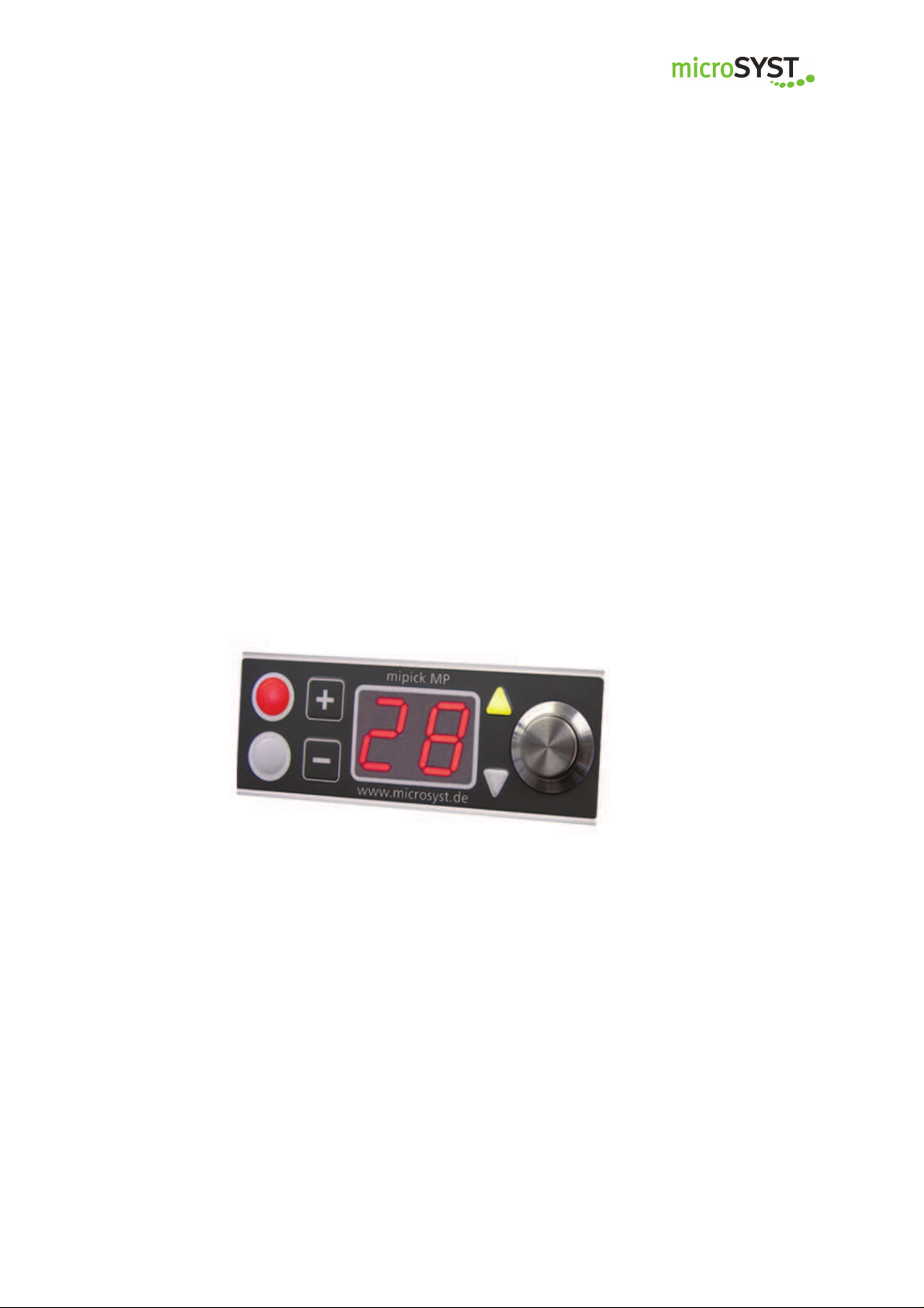
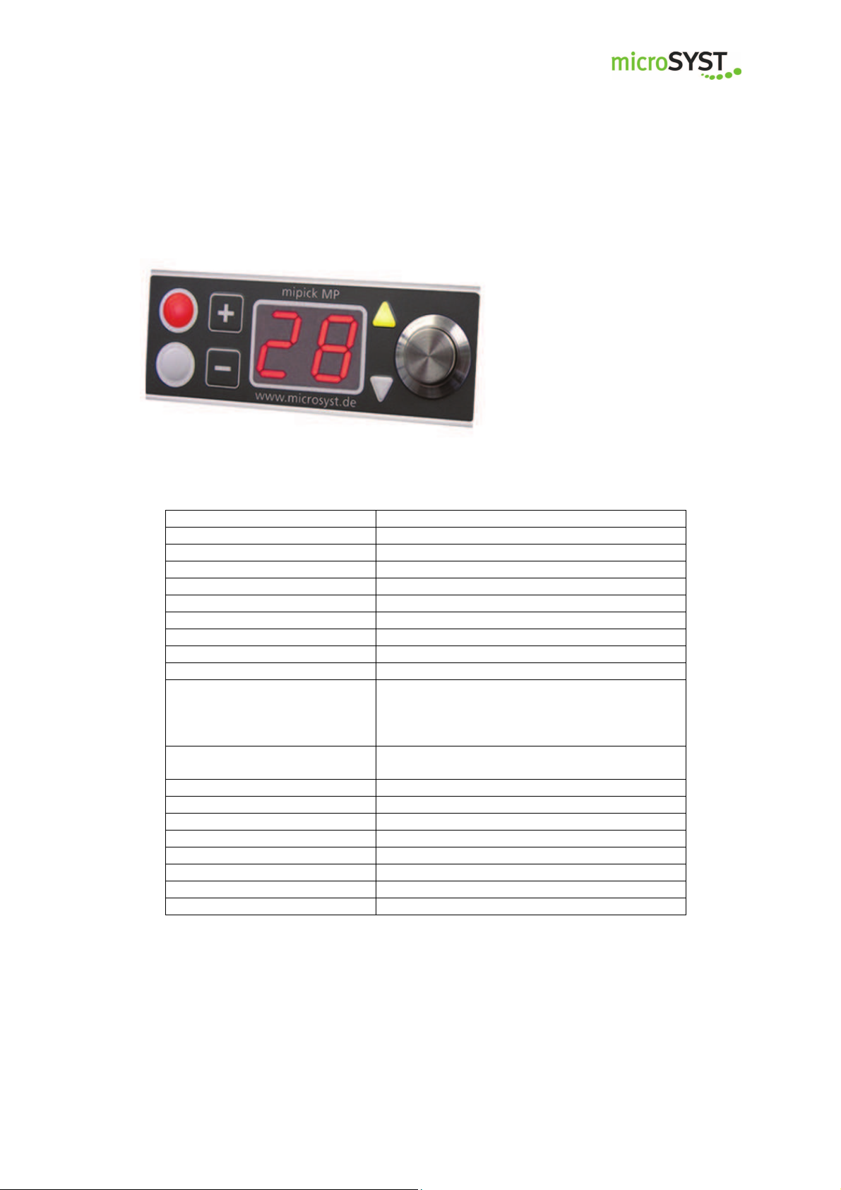
The display is equipped with two LED indicators (red + multi-colored), a metal
confirmation push button and LED directional arrows. A double-digit 7 segment
LED display with a digit height of 14 mm ensures an excellent readability of the
displayed values. Furthermore, a membrane keypad for possible value corrections is available.
The displays communicate via a RS485 interface, the main control system will be
activated via Ethernet and ensures a fast and reliable data transfer.
We are pleased to be able to supply this display also as a complete system with
an individual assembly workplace and a software perfectly tailored to your application.
Page 4
microSYST Systemelectronic GmbH, Am Gewerbepark 11, 92670 Windischeschenbach
Tel. +49 9681 91960-0, Fax +49 9681 91960-10, www.microsyst.de, info@microsyst.de
Page 5
mipick MP
User Manual
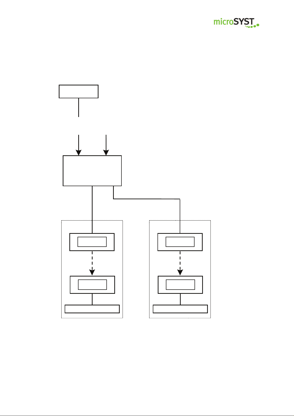
2 System Overview
Controller
Ethernet /
Profibus-DP
Profibus DP
Distribution Unit
230 VAC
The main components of the system are the distribution unit and the pick displays.
The distribution unit is the converter between the
system interface (Ethernet TCP/IP or Profibus DP)
and RS485 and provides the 24 VDC supply power
for the displays.
Two internal connections are available for up to 100
displays.
RS485,
24 VDC
Line 1
Pick Display
Pick Display
Bus Termination
Line 2
Pick Display
Pick Display
Bus Termination
Page 5
microSYST Systemelectronic GmbH, Am Gewerbepark 11, 92670 Windischeschenbach
Tel. +49 9681 91960-0, Fax +49 9681 91960-10, www.microsyst.de, info@microsyst.de
Page 6
Interface
mipick d
isplays
mipick d
isplays
mipick MP
User Manual
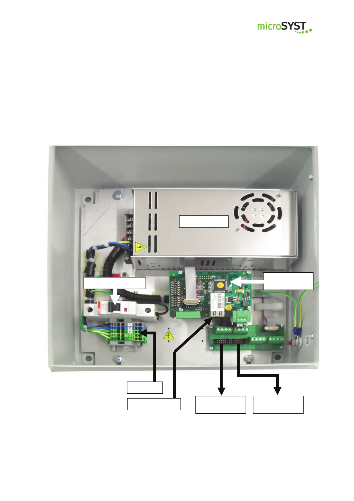
3 Components
3.1 Distribution unit
3.1.1 Distribution unit for Ethernet TCP/IP
Power Supply
Circuit Breaker
Ethernet/mipick
230 VAC
Ethernet TCP/IP
Line 2
Line 1
Page 6
microSYST Systemelectronic GmbH, Am Gewerbepark 11, 92670 Windischeschenbach
Tel. +49 9681 91960-0, Fax +49 9681 91960-10, www.microsyst.de, info@microsyst.de
Page 7
LED Status
Meaning
mipick MP
User Manual
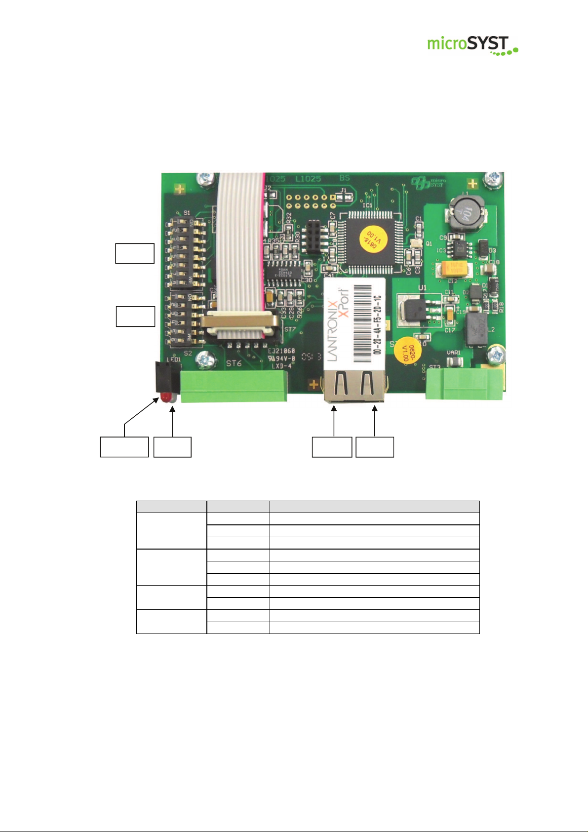
Interface Ethernet / mipick
S1
S2
FAULT
RUN LINK ACT
Green Full-Duplex
ACT
LINK
FAULT
RUN
Yellow Half-Duplex
Off No network activity
Green Physical network connection with 100 MBaud
Yellow Physical network connection with 10 MBaud
Off No physical network connection
Red No active TCP/IP connection
Off Active TCP/IP connection
Green No data traffic at the serial interface
Blinking Data traffic at the serial interface
Page 7
microSYST Systemelectronic GmbH, Am Gewerbepark 11, 92670 Windischeschenbach
Tel. +49 9681 91960-0, Fax +49 9681 91960-10, www.microsyst.de, info@microsyst.de
Page 8
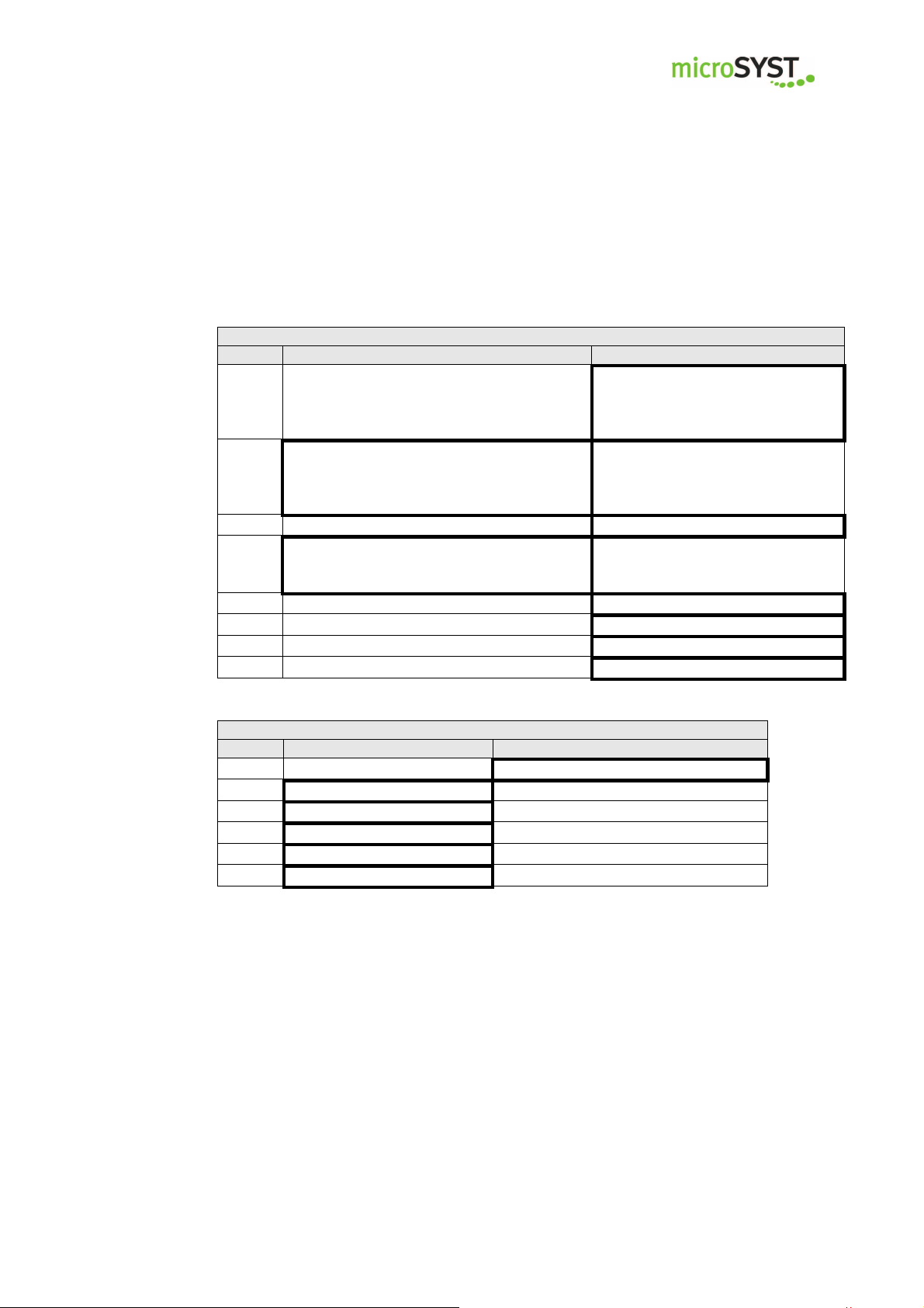
Switch S1: Options
DIP ON OFF
Switch S2: RS485 bus termination
DIP ON OFF
mipick MP
Positions marked with “
Bold-framed positions are the default.
Test mode:
Every display shows its own RS485 ad-
1
dress. There should be no Ethernet communication at the same time!
Use 128 RS485 addresses (0...127) for
the RS485 cycle, bus participant message
2
C2 allowed
3 ■
Send bus participant messages (C1, C2)
4
automatically when changing (and after
the Ethernet connection)
5 ■
6 ■
7 ■
8 ■
User Manual
■
” are fixed and may not be changed!
Standard mode
Use 64 RS485 addresses (0...63)
for the RS485 cycle,
bus participant message C2 not
allowed
Send bus participant messages
(C1, C2) on request only (C0, C1
or C2)
1 ■
2 ■
3 ■
4 ■
5 Bus termination is set no bus termination
6 Bus termination is set no bus termination
The bus termination must be set if the interface comes first in the RS485
bus.
Page 8
microSYST Systemelectronic GmbH, Am Gewerbepark 11, 92670 Windischeschenbach
Tel. +49 9681 91960-0, Fax +49 9681 91960-10, www.microsyst.de, info@microsyst.de
Page 9

Power
Interface
Circuit Breaker
mipick displays
mipick
displays
mipick MP
User Manual
3.1.2 Distribution unit for Profibus-DP
supply
230 VAC
Profibus IN
line 2
Profibus OUT
Profibus/mipick
line 1
Page 9
microSYST Systemelectronic GmbH, Am Gewerbepark 11, 92670 Windischeschenbach
Tel. +49 9681 91960-0, Fax +49 9681 91960-10, www.microsyst.de, info@microsyst.de
Page 10
LED Status
Meaning
mipick MP
User Manual
Interface Profibus / mipick
S2
S1 S3
off Profibus DP connection established
no cyclical Profibus DP communication
or RAM error (if green LED is off)
no RS485 response (within the last 500 ms) or RS485
communication stopped because a new status message is
available and the former status message has not yet been
confirmed (DP-OUT-QBS must be set to DP-IN-TBS)
Profibus DP toggle byte has been changed
(command or status message transmitted)
red (FAULT)
green (RUN)
on
flashing
off Controller is not working (hardware error)
on Controller is working
short off
(flickering)
Page 10
microSYST Systemelectronic GmbH, Am Gewerbepark 11, 92670 Windischeschenbach
Tel. +49 9681 91960-0, Fax +49 9681 91960-10, www.microsyst.de, info@microsyst.de
Page 11
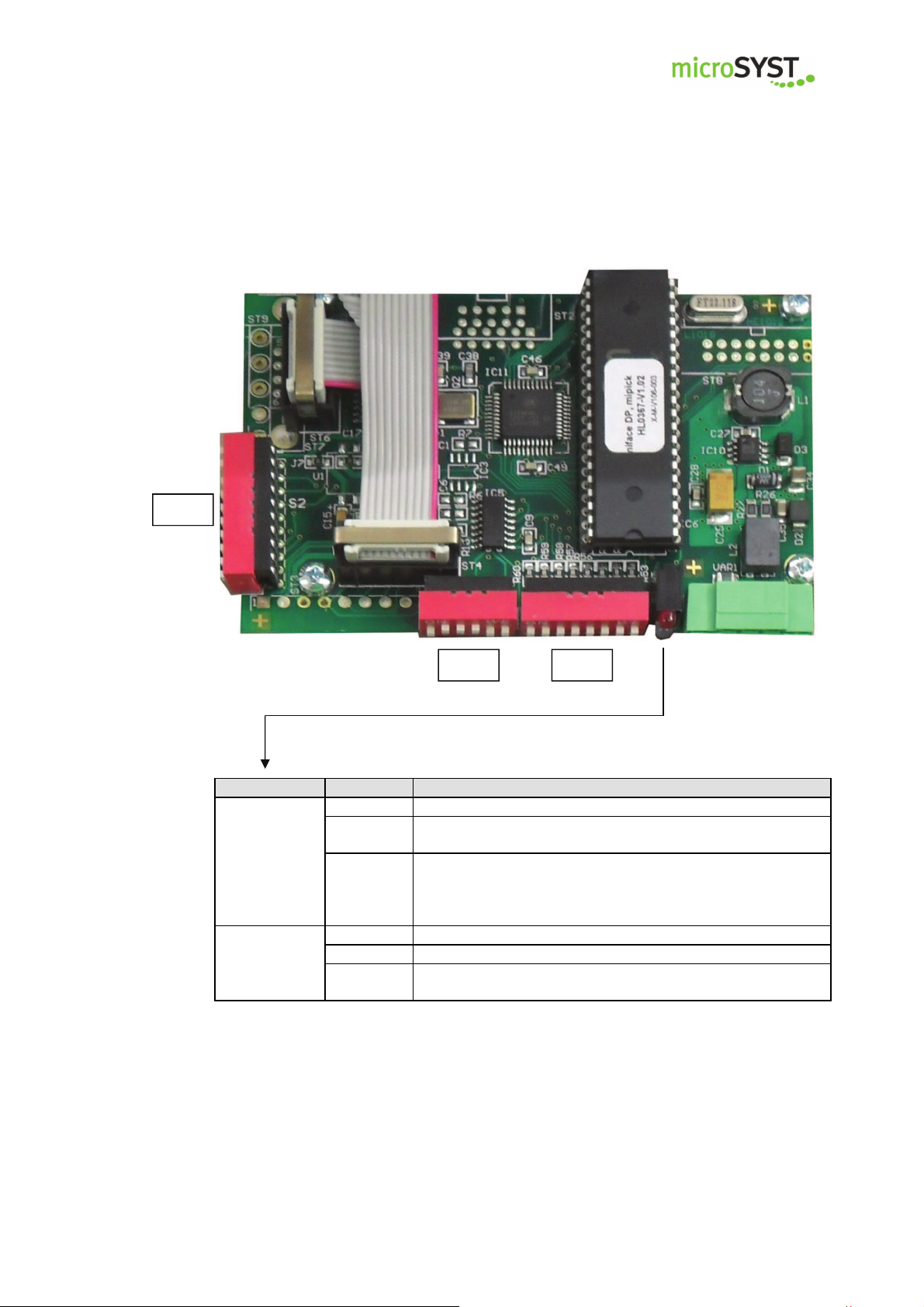
Switch S1: RS485 Bus Termination
DIP ON OFF
Switch S2: DP address, DP bus t
ermination
DIP Function
Switch S3: Options
DIP ON OFF
mipick MP
Positions marked with “
Bold-framed positions are the default.
1 ■
2 ■
3 ■
4 ■
5
6
1
2
3 DP address Bit 22 (ON = 4)
4 DP address Bit 23 (ON = 8)
5 DP address Bit 24 (ON = 16)
6 DP address Bit 25 (ON = 32)
7 DP address Bit 26 (ON = 64)
8 reserved (= OFF ■)
9 both ON: Profibus bus termination set
10
Bus termination is set no bus termination
both OFF: no Profibus bus termination set
User Manual
■
DP address Bit 20 (ON = 1)
DP address Bit 21 (ON = 2)
” are fixed and may not be changed!
Bus termination must
be set if the interface
comes first in the
RS485 bus.
Only DP addresses 0
to 126 are allowed.
Test mode:
Every display shows its own RS485 ad1
dress. There should be no Profibus commu-
nication at the same time!
Use 128 RS485 addresses (0...127) for the
RS485 cycle, bus participant message C2
2
allowed
Transmit every status message immediately
3
(separately) to the DP master
(-> easier handling but slower)
Send bus participant messages (C1, C2) au-
tomatically when changing (and after power4
up and every restart of the DP communica-
tion
5 ■
6 ■
7 ■
8 ■
Standard mode
Use 64 RS485 addresses (0...63)
for the RS485 cycle,
bus participant message C2 not allowed
Collect status messages until DP-IN
buffer is full or the current polling
cycle has been finished.
Send bus participant messages
(C1, C2) on request only (C0, C1 or
C2)
Page 11
microSYST Systemelectronic GmbH, Am Gewerbepark 11, 92670 Windischeschenbach
Tel. +49 9681 91960-0, Fax +49 9681 91960-10, www.microsyst.de, info@microsyst.de
Page 12
mipick MP
User Manual
3.2 Pick displays
3.2.1 Pick display mipick MP20
Technical data
Display type:
Character height:
Digits:
Display colour:
Operating voltage:
Current consumption:
Data input:
Display:
Addresses:
Keypad:
Safety push button:
Signal lamp:
Housing:
Dimensions:
Shaft depth incl. display:
Housing colour:
Mounting:
Protection:
Operating temperature:
Storage temperature:
7 segment LED
14 mm
2 (numeric)
rot
24 VDC +/-20 %
32 mA at 24 V (0,77 W)
RS485 with 115 kBaud
see chapter “Displayable Characters”
0…99
membrane keypad with 2 buttons
metal design,
mechanical service life: > 1.000.000 cycles,
diameter 12 mm,
separately replaceable
1 x LED red, 1 x LED multicoloured,
LED diameter: 8 mm
aluminium, anodised
80 x 30 mm (w x h)
30 mm
natural with grey foil
snap-on mounting
front panel IP40
0...+50°C
-25...+70°C
Page 12
microSYST Systemelectronic GmbH, Am Gewerbepark 11, 92670 Windischeschenbach
Tel. +49 9681 91960-0, Fax +49 9681 91960-10, www.microsyst.de, info@microsyst.de
Page 13
mipick MP
User Manual
3.2.2 Pick display mipick MP80
Technical data
Display type:
Character height:
Digits:
Display colour:
Operating voltage:
Current consumption:
Data input:
Display:
Addresses:
Keypad:
Safety push button:
Signal lamp:
Housing:
Dimensions:
Shaft depth incl. display: 30 mm
Housing colour:
Mounting:
Protection:
Operating temperature:
Storage temperature:
SMD-LED-Dot-Matrix
14 mm
8 (alphanumerisch)
red
24 VDC +/-20 %
90 mA bei 24 V (2,16 W)
RS485 with 115 kBaud
see chapter “Displayable characters”
0…99
Membrane keypad with 2 buttons
Metal design,
mechanical service life: > 1.000.000 cycles,
diameter 12 mm,
separately replacable
1 x LED rot,
1 x LED mulitcoloured (red, green, blue, yellow, cyan, magenta,
white),
LED diameter: 8 mm
aluminium, anodised
170 x 30 mm (w x h)
natural with grey foil
snap-on mounting
front panel IP40
0...+50°C
-25...+70°C
Page 13
microSYST Systemelectronic GmbH, Am Gewerbepark 11, 92670 Windischeschenbach
Tel. +49 9681 91960-0, Fax +49 9681 91960-10, www.microsyst.de, info@microsyst.de
Page 14

mipick MP
3.2.3 Addressing
The address settings can be made either manually via buttons or automatically
with the help of the software “miprog”.
Addressing via buttons
In case that only individual displays have to be programmed (e.g. when replacing
a display) the addressing via buttons is the easiest way. No data connection has
to be available, the pick display has only to be supplied with voltage.
• Please press the enter button and „+“ at the same time.
• Plug in the power supply.
• Please set the required address with the buttons „+“ and „-“.
• Press the enter button.
Addressing via software
This is used for the programming of complete picking systems. All displays on the
RS485 sub bus can be programmed easily.
Regarding systems with Ethernet the addressing will be done via the Ethernet interface.
Regarding systems with Profibus the addressing is done via RS485. For this, disconnect the RS485 bus between distribution unit and the displays and connect it
again with the configuration PC via an USB/RS485 converter.
• Please select the interface and press the button “Verbindung herstellen/create connection”
User Manual
Page 14
microSYST Systemelectronic GmbH, Am Gewerbepark 11, 92670 Windischeschenbach
Tel. +49 9681 91960-0, Fax +49 9681 91960-10, www.microsyst.de, info@microsyst.de
Page 15

mipick MP
• Select the start address of the first pick display and (if you have more displays) the option “automatisch weiter Adressieren” (= continue automatically with addressing).
• By pressing the button “Adressierung starten” (= start addressing), the
currently assigned RS485 address will be indicated.
User Manual
• Now, the LEDs of all displays are flashing and the currently assigned address will be indicated everywhere. Please press this confirmation button
of the display, which shall receive this current address.
• The current address will now be indicated in the software.
Continue until all displays of the bus have been assigned.
You can stop the programming with the button “Adressierung beenden” (= stop
addressing).
Page 15
microSYST Systemelectronic GmbH, Am Gewerbepark 11, 92670 Windischeschenbach
Tel. +49 9681 91960-0, Fax +49 9681 91960-10, www.microsyst.de, info@microsyst.de
Page 16

microSYST Systemelectronic GmbH, Am Gewerbepark 11, 92670 Windischeschenbach
Tel. +49 9681 91960-0, Fax +49 9681 91960-10, www.microsyst.de, info@microsyst.de
mipick MP User Manual
4 Wiring
Page 16
Page 17

mipick MP
4.1 Distribution Unit
Power supply (230 VAC)
System Interface
Ethernet: Profibus DP
User Manual
Display Interface
RS485 bus and power supply are provided for each display line.
line 2 line 1
to the display shaft
IN OUT
Page 17
microSYST Systemelectronic GmbH, Am Gewerbepark 11, 92670 Windischeschenbach
Tel. +49 9681 91960-0, Fax +49 9681 91960-10, www.microsyst.de, info@microsyst.de
Page 18

mipick MP
4.2 Display shaft
In the side shaft cover a screw joint is mounted. Through a slotted protective hose
the flat ribbon cable will be inserted into the shaft.
4.3 mipick
User Manual
from distribution unit
4.4 Bus termination
After the last display of the line the bus termination board will be connected:
Page 18
microSYST Systemelectronic GmbH, Am Gewerbepark 11, 92670 Windischeschenbach
Tel. +49 9681 91960-0, Fax +49 9681 91960-10, www.microsyst.de, info@microsyst.de
Page 19

mipick MP
User Manual
5 Ethernet
5.1 Configuration of the Ethernet Interface
The distribution unit is preset with the following network settings:
IP address: 192.168.4.200
Net mask: 255.255.255.0
Port: 10001
In order to change these parameters please proceed as follows:
Information for Windows 7 users:
The Telnet client must be activated:
Start Control Panel Programs Activate or deactivate Windows features
Telnet Client
• Switch the supply power on and connect the distribution unit to a network
hub by using a RJ45 cable (1:1 cable) or directly to a PC (crosslink cable).
• Start the “MS DOS entry prompt” at your Windows PC.
Please note that with Windows 7 you must have extended rights:
Start All Programs Accessories right mouse click on Command
Prompt Run as Administrator
•
Enter the desired IP address of the interface into the ARP table:
ARP -S XXX.XXX.XXX.XXX xx-xx-xx-xx-xx-xx <CR>
XXX.XXX.XXX.XXX : required IP address
xx-xx-xx-xx-xx-xx : Ethernet MAC address of the interface
(see label on the RJ45 socket)
Page 19
microSYST Systemelectronic GmbH, Am Gewerbepark 11, 92670 Windischeschenbach
Tel. +49 9681 91960-0, Fax +49 9681 91960-10, www.microsyst.de, info@microsyst.de
Page 20

mipick MP
• Create a Telnet connection to port 1:
TELNET XXX.XXX.XXX.XXX 1 <CR>
This connection will fail (disconnection within 3 seconds). However, the IP
address of the interface has been temporarily changed.
Close the Telnet window after acknowledging the error message.
• Create a Telnet connection to port 9999:
TELNET XXX.XXX.XXX.XXX 9999 <CR>
After the connection, press immediately the enter key (within 5 seconds) in
order to enter the setup mode.
• Please do never select “7” (Defaults).
These settings do not fit the system.
• Enter “0” (Server).
• Enter the required IP address and press the enter key.
• Please press the enter key until
”Netmask: Number of Bits for Host Part (…)“ is selected.
Enter here the number of free bits for the IP address,
e.g. “8“ for a netmask of 255.255.255.0
(=11111111.11111111.11111111.00000000) or
“11“ for the netmask of 255.255.248.0
(=11111111.11111111.11111000.00000000) and press the enter key.
• Please press the enter key until “Your choice?” is selected.
• Press “9” to save all settings ( the Telnet connection will be interrupted).
The configuration of the Ethernet interface is now completed.
The telegram for controlling can now be transmitted via the selected IP address
(TCP/IP connection via port 10001).
User Manual
Page 20
microSYST Systemelectronic GmbH, Am Gewerbepark 11, 92670 Windischeschenbach
Tel. +49 9681 91960-0, Fax +49 9681 91960-10, www.microsyst.de, info@microsyst.de
Page 21

A L D
A
L
D
mipick MP
5.2 Ethernet Communication
The Ethernet interface of the distribution unit allows communication between a controller (for example PC or PLC) and the mipick devices.
“Commands” will be sent from the controller to the interface via Ethernet and will
then be transmitted to the respective mipick devices.
“Status messages” will be sent from the mipick devices to the interface via RS485
and will then be transmitted to the controller via Ethernet.
The Ethernet interface represents the “bus master” at the RS485 level.
Should there be no “commands”, the bus-sharing units (mipick devices) will cycli-
cally be polled (address order 0 to 63, 0 to 63, … or 0 to 127, 0 to 127,…). If an
event occurs (e.g. “button has been pressed”), the bus-sharing unit (mipick devices)
replies accordingly and a related “status message” will be sent via Ethernet.
Should there be a “command” for a certain RS485 address, it will be sent to the bussharing unit (mipick devices) instead of the polling telegram. The reply of the mipick
device will be reported via the Ethernet.
Should there be a new added bus-sharing unit or a former existing bus sharing unit
which does not respond (correctly), a special telegram via Ethernet will be sent. The
controller can explicitly request this “bus participant telegram” in order to receive the
current bus status.
For further information on commands and “status messages” please see chapter
“Telegram Structure”.
Their structure is as follows:
User Manual
ddress of the pick display
1 byte 1 byte n bytes
Page 21
microSYST Systemelectronic GmbH, Am Gewerbepark 11, 92670 Windischeschenbach
Tel. +49 9681 91960-0, Fax +49 9681 91960-10, www.microsyst.de, info@microsyst.de
ength of the data
ata
Page 22

mipick MP
5.2.1 Sending commands
The commands are transmitted from the control computer to the Ethernet interface
and from there via an RS485 bus to the respective mipick device.
With each TCP/IP telegram, one or more commands (completely) can be transmitted to the Ethernet interface. Every command has the following structure “address”,
“length” and “data”.
Please note that it is not possible to send a new command to a certain address before the last command has been answered or at least approximately 1 second has
passed (in this case, the bus participant has not answered or has not answered correctly.
After a “broadcast command” please wait for the command confirmations (one per
existing bus participant) before sending a new command. A waiting period of 1 second will be enough.
Note: If more than one command confirmations are pending, they do not necessarily
have to arrive in the same order as the commands have been sent. It can also be
possible to receive an “event message” or “bus participant message”!
Example:
The value “12“ shall appear on display 4:
Send the command via TCP/IP (in HEX format):
04 08 80 20 20 31 32 00 00 00
(address = 4, length = 8 bytes, data = 80 20 20 31 32 00 00 00)
User Manual
Page 22
microSYST Systemelectronic GmbH, Am Gewerbepark 11, 92670 Windischeschenbach
Tel. +49 9681 91960-0, Fax +49 9681 91960-10, www.microsyst.de, info@microsyst.de
Page 23

mipick MP
5.2.2 Receiving Status Messages
There are three types of status messages:
1. Command confirmations (= command responses)
2. Event messages (e.g. “button was pressed“)
3. Bus participant messages (“device was removed/added”)
Status messages are sent to the control computer with a TCP/IP telegram. Every
TCP/IP telegram can contain one or more status messages (completely). Every status message has the following structure “address”, “length” and “data”.
Examples:
a) Command confirmation concerning above mentioned command:
Receiving the command confirmation via TCP/IP (in HEX format):
04 01 80
(address = 4, length = 1, data = 80)
b) Press the button of display 4:
04 03 00 81 0C
c) Release the button of display 4:
04 03 00 80 0C
Important: With regard to above mentioned example only one status message is transferred but should there be more than one status messages they will be transmitted at
the same time.
User Manual
Page 23
microSYST Systemelectronic GmbH, Am Gewerbepark 11, 92670 Windischeschenbach
Tel. +49 9681 91960-0, Fax +49 9681 91960-10, www.microsyst.de, info@microsyst.de
Page 24

Byte no.
Data identifier
Number of bytes
Function / Description
mipick MP
User Manual
6 Profibus DP
6.1 Configuration of the Profibus Interface
6.1.1 GSD file
The device database file „micr05D0“, which is part of the delivery is used for the
integration of the Profibus DP interface (DP slave) into the Profibus. This file
contains the necessary identifiers for the configuration of the input/output data
widths (please see next chapter).
6.1.2 Configuration data
Via the configuration the data width of the cyclic data exchange can be set individually. Therefore, the following identifiers (max. 30) must be selected in any
order.
The DP master transmits the identifier to the DP slave before it starts the cyclic
data exchange.
x 0x10 1 Input Data
x 0x11 2 Input Data
: :
x 0x1F 16 Input Data
x 0x20 1 Output Data
x 0x21 2 Output Data
: :
x 0x2F 16 Output Data
x 0x30 1/1 Input/Output Data (1 byte each)
x 0x31 2/2 Input/Output Data (2 bytes each)
: :
x 0x3F 16/16 Input/Output Data (16 bytes each)
The minimum number of input or output bytes is 6 bytes each.
The maximum number of input or output bytes is 200 bytes each, but the length
of 300 bytes (input + output) may not be exceeded.
Standard configuration: 0x3F, 16 input / output bytes.
Page 24
microSYST Systemelectronic GmbH, Am Gewerbepark 11, 92670 Windischeschenbach
Tel. +49 9681 91960-0, Fax +49 9681 91960-10, www.microsyst.de, info@microsyst.de
Page 25

mipick MP
6.1.3 User parameter data
The „User_Prm_Data“ is not used by the interface. But nevertheless it will be
checked if the Profibus master transfers any User_Prm_Data. If
User_Prm_Data is transferred, the Profibus initialization will be rejected and the
slave’s parameters must be reconfigured.
Note:
Standard parameters configuration is necessary and is normally added by the
used DP configurators.
6.1.4 Diagnostic data
The interface does not support any extended diagnostic data. Default diagnosis
is used.
User Manual
Page 25
microSYST Systemelectronic GmbH, Am Gewerbepark 11, 92670 Windischeschenbach
Tel. +49 9681 91960-0, Fax +49 9681 91960-10, www.microsyst.de, info@microsyst.de
Page 26

DP-OUT:
DP-IN:
mipick MP
6.2 DP Communication
For the DP master the Profibus interface (DP slave) is a standard I/O device. This
means, there are DP output data which are cyclically transmitted to the slave and
DP input data which are cyclically received from the slave.
The structure of the I/O data is as follows:
TBK: Toggle byte for the commands
QBK: Confirmation byte for the commands (= TBK after data transfer)
LBK: Length byte for the commands
TBS: Toggle byte for the status messages
QBS: Confirmation byte for the status messages (= TBS after data transfer)
LBS: Length byte for the status messages
A: Address of the pick displays
L: Length of the data
D: Data (max. 20 bytes)
For more information on commands and status messages please see chapter “Telegram structure”.
Information:
After the (re)start of the Profibus DP communication all DP-OUT bytes and all DP-IN
bytes have the value 0.
With the help of the configuration, the number of DP IN bytes and DP OUT bytes
has to be defined in such a way that the longest possible command or the longest
possible status message has enough space. The maximum I/O width may not be
exceeded (please see chapter „configuration data“).
User Manual
TBK QBS LBK A L D A L D … A L D
QBK TBS LBS A L D A L D … A L D
Commands
Status messages
Page 26
microSYST Systemelectronic GmbH, Am Gewerbepark 11, 92670 Windischeschenbach
Tel. +49 9681 91960-0, Fax +49 9681 91960-10, www.microsyst.de, info@microsyst.de
Page 27

mipick MP
6.2.1 Transmitting commands
Commands are used to define what the displays should indicate or what they should
do. The commands will be transmitted from the DP master to the Profibus interface
(DP slave) and from here via the RS485 bus to the respective displays.
Instructions:
1. Enter the command or also more commands (completely) in the DP OUT “commands. Every command consists of “address“, “length“ and “data“.
2. Enter the length of all command bytes into “LBK“.
3. Then, “TBK“ will be increased by one.
4. Now, the DP slave starts to evaluate the commands and transmit them to the
corresponding displays. Once this process is completed, the “QBK“ is set to the
value of the previous changed “TBK“.
5. If there are further commands available please continue with item 1.
Example:
The value “12“shall appear on display 4:
1. Enter the command:
DP OUT(hex) = 00 XX 00 04 08 80 20 20 31 32 00 00 00
2. Set “LBK“: ▼
DP OUT(hex) = 00 XX 0A 04 08 80 20 20 31 32 00 00 00
3. Increase “TBK“: ▼
DP OUT(hex) = 01 XX 0A 04 08 80 20 20 31 32 00 00 00
4. Wait for “QBK“:
DP IN(hex) = 00 XX XX XX ...
DP IN(hex) = 01 XX XX XX ...
User Manual
▼
Page 27
microSYST Systemelectronic GmbH, Am Gewerbepark 11, 92670 Windischeschenbach
Tel. +49 9681 91960-0, Fax +49 9681 91960-10, www.microsyst.de, info@microsyst.de
Page 28

mipick MP
6.2.2 Receiving status messages
There are three types of status messages:
1. Command confirmations (= command responses)
2. Event messages (e.g. “button has been pressed“)
3. Bus participants messages (“device has been removed/added“)
This status messages has to be retrieved from the DP master in the shortest possible time, otherwise the RS485 communication with the displays can slow down or
even stop (until the status messages are retrieved)!
Instructions:
1. If the “TBS“changes, there are status messages which must be retrieved.
2. The status messages which must be retrieved are available in the DP IN “status
messages“(completely, in total “LBS“ bytes). Every status message consists of
“address“, “length“and “data“.
3. After the status messages have been retrieved out the DP master must set the
“QBS“to the same value of “TBS“. This should made made as quick as possible
(not to slow down the RS485 communication).
4. Continue with item 1.
Examples:
a) Command confirmations concerning the above mentioned command:
1. “TBS“ has been changed:
DP IN(hex) = XX 00 XX XX XX ...
▼
DP IN(hex) = XX 01 03 04 01 80
2. Read out the status message:
“LBS” = 3
“Address“ = 4
“Length“ = 1
“Data“ = 80H (command confirmation)
3. Set “QBS” to the value of “TBS”:
DP OUT(hex) = XX 01 XX XX XX ...
User Manual
▼
Page 28
microSYST Systemelectronic GmbH, Am Gewerbepark 11, 92670 Windischeschenbach
Tel. +49 9681 91960-0, Fax +49 9681 91960-10, www.microsyst.de, info@microsyst.de
Page 29

mipick MP
b) Press the button of display 4:
1. “TBS“ has been changed:
DP IN(hex) = XX 01 XX XX XX ...
DP IN(hex) = XX 02 05 04 03 00 81 0C
2. Read out the status message:
“LBS” = 5
“Address“ = 4
“Length“ = 3
“Data“ = 00H 81H 0CH (event message: button pressed, display value = “12“)
3. Set “QBS” to the value of “TBS”:
DP OUT(hex) = XX 02 XX XX XX ...
Note:
In the above mentioned examples only one status message has been transmitted.
If there are more than one status messages available they are transmitted at the
same time in order to use the available DP IN bytes in the best possible way and to
speed up the communication.
If the DIP switch S3-3 is set to ON every status message will be reported separately
(in order to simplify the evaluation of the DP master).
User Manual
▼
▼
Page 29
microSYST Systemelectronic GmbH, Am Gewerbepark 11, 92670 Windischeschenbach
Tel. +49 9681 91960-0, Fax +49 9681 91960-10, www.microsyst.de, info@microsyst.de
Page 30

Address
Length
Command
1.
Parameter
... n. Parameter
s
Address
Length
Command confirmation
Possible reply data
Event
n th
Parame-
mipick MP
User Manual
7 Telegram structure
7.1 Structure of commands
Data
0…127,
255*
Number of bytes
to be transferred
*Address = 255: broadcast command:
This command will be sent to all possible bus addresses (0...63 or 0...127). Only
the really existing MIPICKS of the bus which support the command will evaluate it
and respond with a “command confirmation”.
7.2 Structure of status messages
z.B. 80H
= “controlling the
display”
7.2.1 Command confirmation
Data
0…127 >= 1 z.B. 80H
Every command will be acknowledged by sending a command confirmation. This
ensures the complete communication cycle, from the control computer to the
MIPICKS and back. If necessary, reply data from the MIPICK will be transmitted.
7.2.2 Event message
Data
Address Length
Number of
0…127
bytes to be
transferred
message
00H
Status byte 1 th Parameter ...
Contains (bit-coded) in-
formation to the event
Additional event information
if the space of status byte is not
enough
All existing MIPICKs on the RS485 bus (addresses 0 to 63 or 0 to 127) will always
be polled. If a status byte will be unequal 0 OR at least one additional “parameter
byte” will be received an event occurs. It will then be transmitted from the interface
to the control computer.
ter
Page 30
microSYST Systemelectronic GmbH, Am Gewerbepark 11, 92670 Windischeschenbach
Tel. +49 9681 91960-0, Fax +49 9681 91960-10, www.microsyst.de, info@microsyst.de
Page 31

Bus participant
Adresse
Länge
“Interface Command“
mipick MP
User Manual
7.2.3 Bus participant message
If the related DIP switch is set to “ON“ the bus participants messages will be sent
automatically ...
• after every change (new bus participant identified or not available anymore)
• after every communication restart = start of the cyclic DP data exchange or the
TCP/IP connection (after completion of the currently running polling cycle).
Data
Adress Length
255 9
message
C1H
(bus addresses
0…63)
C2H
(bus addresses
64…127,
only if 128 ad-
dresses are set
via DIP switch)
Bus participant status of
the addresses 0…7 or
64… 71:
(bit 0…7)
1 = device available,
0 = device not available
BTN0 ... BTN7
... Bus participants status of
the addresses 56…63 or
120…127:
Bit 0…7:
1 = device available,
0 = device not available
The bus participant messages can be requested by transmitting the following command:
Data
C1H : Request a bus participant message C1H
255 1
C2H : Request a bus participant message C2H (if 128 addresses)
C0H : Request a bus participant messages C1H and C2H (if 128 addresses)
Page 31
microSYST Systemelectronic GmbH, Am Gewerbepark 11, 92670 Windischeschenbach
Tel. +49 9681 91960-0, Fax +49 9681 91960-10, www.microsyst.de, info@microsyst.de
Page 32

1 2 3
Address
Length
Command
4 5 6 7
Text of digit 1
Text of digit 2
Value of digit 1
Value of digit 2
8 9
Options 1
Options 2
10
Optionen 3
mipick MP
User Manual
7.3 Control command mipick MP20
Command (10 bytes):
0…127, 255 = Broadcast 8 80H
ASCII code (20...7FH) ASCII code (30...39H, 20H = empty)
+ Bit 7 = 1, if decimal point is required
Bit 0=0: LED 1 (on the top) off
=1: LED 1 (on the top) on*
Bit 1=1: LED 1 slowly flashing
Bit 2=1: LED 1 fast flashing
Bit 5-3: 000 = LED 2 (below) off
001 = blue*
010 = green*
100 = red*
110 = yellow*
011 = cyan*
101 = magenta*
111 = white*
Bit 6=1: LED 2 slowly flashing
Bit 7=1: LED 2 fast flashing
*Bit must be set for flashing
Bit 0=1: Arrow “up“ on
Bit 1=1: Arrow “down“ on
Bit 2=1: Display slowly flashing
Bit 3=1: Display fast flashing
Bit 4=1: LEDs will be deleted automatically,
if one of the two inputs will be closed
Bit 5=1: LEDs will be deleted automatically,
if one of the two inputs will be closed
Bit 7, 6: Brightness:
00 = bright
01 = :
10 = :
11 = dark
Bit 0=0: Suppress leading zeros
=1: Display leading zeros
Bit 1=1: +/- keys locked
Bit 2=1: +/- counts endlessly (0 to 99)
=0: +/- counts from 0 to preset value
Bit 4, 3: cycle duration until change
value – text
00 = 2 s
01 = 1.5 s
10 = 1.1 s
11 = 0.8 s
Bit 5=0 do not report keystrokes +/ 5=1: report keystrokes +/-
Bit 7, 6: reserved (=0)
Page 32
microSYST Systemelectronic GmbH, Am Gewerbepark 11, 92670 Windischeschenbach
Tel. +49 9681 91960-0, Fax +49 9681 91960-10, www.microsyst.de, info@microsyst.de
Page 33

1 2 3
Address
Length
Command confirmations
1 2 3 4 5
Event
mipick MP
User Manual
Command confirmation (3 bytes):
0…127 1 80H
Event message (5 bytes):
Address Length
0…127 3 00 H
Message
Bit 0 : Input 1 (ST3)
0: Contact OPEN
1: Contact CLOSED
Bit 1 : Input 2 (ST5)
0: Contact OPEN
1: Contact CLOSED
Bit 2: Status arrow UP
Bit 3: Status arrow DOWN
Bit 4 : Input button “–“
0: Contact OPEN
1: Contact CLOSED
Bit 5 : Input button “+“
0: Contact OPEN
1: Contact CLOSED
Bit 6=1: Display error reported
Bit 7=1: Change flag for bit 0,1,4 and 5
Status Byte Value
0…99
Notes:
Bytes 6 and 7 (value) of the command determine the real display value of the pick
display. After pressing the confirmation button this value will be reported to the event
message telegram. Also the correction keys “+” and “-“run solely with this value.
Only numbers (30H .. 39H) or space characters (20H) can be used as “value”.
With the bytes 4 and 5 (text) it is possible to display two characters as an additional
text or labeling. The fields “value” and “text” are then displayed alternatively. The cycle time can be adjusted with byte 10 (options 3).
If one of the fields “text” or “value” will not be used two space characters (20H) must
be set in the corresponding position in the telegram. Then, there will be no change
between the two fields on the display.
Page 33
microSYST Systemelectronic GmbH, Am Gewerbepark 11, 92670 Windischeschenbach
Tel. +49 9681 91960-0, Fax +49 9681 91960-10, www.microsyst.de, info@microsyst.de
Page 34

1 2 3
Address
Length
Command
4 5 6 7 8 9
Text of digit
1
Text of digit
2
Text of digit
3
Text of digit
4
Text of digit
5
Text of digit
6
10 11 12 13 14 15
Value of
digit
1 Value of
digit
2 Value of
digit
3 Value of
digit
16 17
Options
1
Options
2
mipick MP
User Manual
7.4 Control command mipick MP80
Command (18 bytes)
0…127
255 = Broadcast
16 88H
ASCII code
20…7FH
ASCII code
20…7FH
ASCII code
20…7FH
ASCII code
20…7FH
ASCII code
20…7FH
ASCII code
20…7FH
Text of digit 7 Text of digit 8
ASCII code
20…7FH
ASCII code
20…7FH
Bit 0=0: LED 1 (on the top) off
=1: LED 1 (on the top) on*
Bit 1=1: LED 1 slowly flashing
Bit 2=1: LED 1 fast flashing
Bit 5-3: 000 = LED 2 (below) off
001 = blue*
010 = green*
100 = red*
110 = yellow*
011 = cyan*
101 = magenta*
111 = white*
Bit 6=1: LED 2 slowly flashing
Bit 7=1: LED 2 fast flashing
*Bit must be set for flashing
Only the following bits will be evaluated:
Option 1 (byte 16): all bits
Option 2 (byte 17): bit 0,1,4,5,6,7
Option 3 (byte 18): bit 5
Text and vaue (bytes 4-15) will be ignored
4
0…9 0…9 0…9 0…9
Bit 0=1: Arrow “up“ on
Bit 1=1: Arrow “down“ on
Bit 2=1: Display slowly flashing
Bit 3=1: Display fast flashing
Bit 4=1: LEDs will be deleted automatically,
if one of the two inputs will be closed
Bit 5=1: LEDs will be deleted automatically,
if one of the two inputs will be closed
Bit 7, 6: Brightness:
00 = bright
01 = :
10 = :
11 = dark
Page 34
microSYST Systemelectronic GmbH, Am Gewerbepark 11, 92670 Windischeschenbach
Tel. +49 9681 91960-0, Fax +49 9681 91960-10, www.microsyst.de, info@microsyst.de
Page 35

18
Options
3
1 2 3
Address
Length
Command
confirmation
mipick MP
User Manual
Bit 0=0: Suppress leading zeros
=1: Display leading zeros
Bit 1=1: +/- keys locked
Bit 2=1: +/- counts endlessly (0 to 9999)
=0: +/- counts from 0 to preset value
Bit 4, 3: cycle duration until change
value – text
00 = 2 s
01 = 1.5 s
10 = 1.1 s
11 = 0.8 s
Bit 5=0 do not report keystrokes +/ 5=1: report keystrokes +/-
Bit 6: reserved (=0)
Bit 7=1 only evaluate options
Command Confirmation:
0…127 1 88H
Page 35
microSYST Systemelectronic GmbH, Am Gewerbepark 11, 92670 Windischeschenbach
Tel. +49 9681 91960-0, Fax +49 9681 91960-10, www.microsyst.de, info@microsyst.de
Page 36
1 2 3 4 5 6
Event
1 2 3 5 6
Address
Length
Command
Value
1 2 3 4
Address
Length
Command
Status of the inputs
1 2 3 4
Address
Length
Command
Start checking
mipick MP
User Manual
Event message:
Address Length
0…127 4 00 H
message
Bit 0 : Input 1 (ST3)
0 : Contact OPEN
1 : Contact CLOSED
Bit 1 : Input 2 (ST5)
0 : Contact OPEN
1 : Contact CLOSED
Bit 2: Arrow up status
Bit 3: Arrow down status
Bit 4 : Input key „–“
0 : Contact OPEN
1 : Contact CLOSED
Bit 5 : Input key „+“
0 : Contact OPEN
1 : Contact CLOSED
Bit 6=1: Display error has been detected
Bit 7=1: Change flag for bit 0,1,4 and 5
Status byte Value
Reply to the query regarding the display content (command 05 H):
0…9999
0…127 3 05H 0…9999
Reply to the query regarding the status of the inputs (Kommando 07 H):
Bit 0 = 1: input 1 closed (ST3)
Bit 1 = 1: input 2 closed (ST5)
0…127 2 07H
Bit 2 = 1: „+“ key is pressed
Bit 3 = 1: „-“ key is pressed
Bit 4...7 : reserved (= 0)
Starting the LED error checking:
0…127 2 08H 01
Page 36
microSYST Systemelectronic GmbH, Am Gewerbepark 11, 92670 Windischeschenbach
Tel. +49 9681 91960-0, Fax +49 9681 91960-10, www.microsyst.de, info@microsyst.de
Page 37

1 2 3
Address
Length
Command
1 2 3 4
Address
Length
Command
Reading error
1 2 3 4 5
Address
Length
Command
Total number of LED errors
6 7 8 9 10 11 12 13 14 15
Position
error
1
Position
error
2
Position
error
3
Position
error
4
Position
error
5
Address
Length
Command
mipick MP
User Manual
Starting reply to LED error checking:
0…127 2 08H
Reading an LED error
Before reading an LED error a checking must be started.
The review process takes approximately up to 500 ms.
After that the errors can be read.
0…127 2 08H 00
Reply to reading LED errors:
0…127 13 08H
0 = No error
> 0 = Error
Position Position Position Position Position
A maximum of 5 errror positions will be reported, but the total number of LED errors
can be higher. The error positions are only valid if there are a corresponding numbers
of errors. Otherwise, the reported value will not be valid (=0)
The meaning of the positions is as follows:
0 RGB green
1 RGB red
2 RGB blue
3 LED red
4 LED arrow down
5 LED arrow up
6-334 LED Matrix (47x7 LEDs, line-by-line from top left to the bottom right)
7.5 Additional commands
Displaying addresses
Data
0…127, 255 = Broadcast 1 01H
Page 37
microSYST Systemelectronic GmbH, Am Gewerbepark 11, 92670 Windischeschenbach
Tel. +49 9681 91960-0, Fax +49 9681 91960-10, www.microsyst.de, info@microsyst.de
Page 38

Address
Length
Command
Address
Length
Command
Address
Length
Command
Address
Length
Command
Lamp test
Address
Length
Command
Address
Length
Command
Address
Length
Command
Value
Address
Length
Command
mipick MP
User Manual
Command confirmation:
0...127 1 01H
Deleting a display
0…127, 255 = Broadcast 1 02H
Command confirmation:
0...127 1 02H
Lamp test
Data
Data
Data
Data
0…127, 255 = Broadcast 2 04H
Command confirmation:
Daten
0…127 1 04H
Querying display content
0…127, 255 = Broadcast 1 05H
Command confirmation:
0…127 2 05H 0…99
Querying software version
01H = start
00H = stop
Data
Data
Data
0…127, 255 = Broadcast 1 06H
Command confirmation:
Page 38
microSYST Systemelectronic GmbH, Am Gewerbepark 11, 92670 Windischeschenbach
Tel. +49 9681 91960-0, Fax +49 9681 91960-10, www.microsyst.de, info@microsyst.de
Page 39

Address
Length
Command
SW version (12 bytes)
Address
Length
Command
Address
Length
Command
Input status
mipick MP
User Manual
0…127 13 06H HLxxxx-Vx.xx
Querying input status
0…127, 255 = Broadcast 1 07H
Command confirmation:
0…127 2 07H
Data
Data
Data
Bit 0 = 1: input 1 closed (ST3)
Bit 1 = 1: input 2 closed (ST5)
Bit 2 = 1: „+“ key pressed
Bit 3 = 1: „-“ kex pressed
Bit 4...7: reserved (= 0)
Page 39
microSYST Systemelectronic GmbH, Am Gewerbepark 11, 92670 Windischeschenbach
Tel. +49 9681 91960-0, Fax +49 9681 91960-10, www.microsyst.de, info@microsyst.de
Page 40

Lower
Higher
mipick MP
User Manual
8 Displayable characters
8.1 Pick display MP20
0
1
2
3
4
5
6
7
8
9
A
B
0 1 2 3 4 5 6 7
Segment a* Space
Segment b*
Segment c*
Segment d*
Segment e*
Segment f*
Segment g*
Punkt dp*
C
D
E
F
*Assignment of segments
Page 40
microSYST Systemelectronic GmbH, Am Gewerbepark 11, 92670 Windischeschenbach
Tel. +49 9681 91960-0, Fax +49 9681 91960-10, www.microsyst.de, info@microsyst.de
Page 41

mipick MP
8.2 Pick display MP80
With regard to the pick display MP80 a large part of the ASCII character set (bytes 32
until 127) can be displayed (letters, numbers, special characters).
User Manual
Page 41
microSYST Systemelectronic GmbH, Am Gewerbepark 11, 92670 Windischeschenbach
Tel. +49 9681 91960-0, Fax +49 9681 91960-10, www.microsyst.de, info@microsyst.de
Page 42

Das bezeichnete Produkt stimmt mit
Die Übereinstimmung des bezeichneten Produk-
Richtlinien /
Europäische Norm /
mipick MP
User Manual
9 Declaration of Conformity
EU-Konformitätserklärung
EU Declaration of Conformity
Produktbezeichnung: mipick MP
Product name:
Typenreihe: Controller Box
Type code: mipick MP20
mipick MP80
mipick MP80T
Hersteller: microSYST Systemelectronic GmbH
Manufacturer: Am Gewerbepark 11
92670 Windischeschenbach
der folgenden Europäischen Richtlinie
überein:
We herewith confirm that the above mentioned product meets the requirements of
the following standard:
Directives
EMV Richtlinie
EMC Directive
NiederspannungsRichtlinie
Low Voltage Directive
RoHS Richtlinie
RoHS Directive
Windischeschenbach, 16.11.2016
Manuel Raß
Geschäftsführer / General Manager
2014/30/EU
2014/35/EU
2011/65/EU
tes mit den Vorschriften der angewandten
Richtlinie(n) wird nachgewiesen durch die Einhaltung folgender Normen / Vorschriften:
The conformity of the product described above with
the provisions of the applied Directive(s) is demonstrated by compliance with the following standards /
regulations:
Standard
EN61000-6-2:2005
EN61000-6-3:2007 +A1:2011
EN60950-1:2006 +A11:2009 +A1:2010 +A12:2011
+A2:2013
EN50581:2012
Page 42
microSYST Systemelectronic GmbH, Am Gewerbepark 11, 92670 Windischeschenbach
Tel. +49 9681 91960-0, Fax +49 9681 91960-10, www.microsyst.de, info@microsyst.de
Page 43

mipick MP
User Manual
10 Version overview
Version Date Remarks, Descriptions
1.00
1.10
1.20
Certified per DIN EN ISO 9001.
29.04.14
03.05.16
13.09.17
Document created
Declaration of conformity
Display MP80 has been added
Page 43
microSYST Systemelectronic GmbH, Am Gewerbepark 11, 92670 Windischeschenbach
Tel. +49 9681 91960-0, Fax +49 9681 91960-10, www.microsyst.de, info@microsyst.de
 Loading...