

Page 1
miline S1X4
Line-oriented LED display
User manual
Page 1
Page 2

Contents
1 General information 4
1.1 Legal information . . . . . . . . . . . . . . . . . . . . . . . . . . . . . . . . . . . . 4
1.2 Exclusion of liability . . . . . . . . . . . . . . . . . . . . . . . . . . . . . . . . . . . 4
1.3 Safety instructions . . . . . . . . . . . . . . . . . . . . . . . . . . . . . . . . . . . 4
1.4 Intended use . . . . . . . . . . . . . . . . . . . . . . . . . . . . . . . . . . . . . . 5
1.5 Warranty and liability . . . . . . . . . . . . . . . . . . . . . . . . . . . . . . . . . . 5
1.6 Installation . . . . . . . . . . . . . . . . . . . . . . . . . . . . . . . . . . . . . . . 6
1.7 Disposal . . . . . . . . . . . . . . . . . . . . . . . . . . . . . . . . . . . . . . . . . 6
2 Initial operation 7
2.1 Connection cable . . . . . . . . . . . . . . . . . . . . . . . . . . . . . . . . . . . . 7
2.1.1 Grounding . . . . . . . . . . . . . . . . . . . . . . . . . . . . . . . . . . . . 7
2.1.2 Data / supply cable . . . . . . . . . . . . . . . . . . . . . . . . . . . . . . . 7
2.2 Pin assignment . . . . . . . . . . . . . . . . . . . . . . . . . . . . . . . . . . . . . 8
2.2.1 AD converter . . . . . . . . . . . . . . . . . . . . . . . . . . . . . . . . . . 8
2.2.2 Clock . . . . . . . . . . . . . . . . . . . . . . . . . . . . . . . . . . . . . . 9
2.2.3 Ethernet . . . . . . . . . . . . . . . . . . . . . . . . . . . . . . . . . . . . . 10
2.2.4 Digital inputs . . . . . . . . . . . . . . . . . . . . . . . . . . . . . . . . . . 11
2.2.5 Pulse counter . . . . . . . . . . . . . . . . . . . . . . . . . . . . . . . . . . 12
2.2.6 Profibus . . . . . . . . . . . . . . . . . . . . . . . . . . . . . . . . . . . . . 13
2.2.7 Profinet . . . . . . . . . . . . . . . . . . . . . . . . . . . . . . . . . . . . . 14
2.2.8 RS485 . . . . . . . . . . . . . . . . . . . . . . . . . . . . . . . . . . . . . . 15
2.2.9 Timer . . . . . . . . . . . . . . . . . . . . . . . . . . . . . . . . . . . . . . 16
2.3 Switching on / Switching off the device . . . . . . . . . . . . . . . . . . . . . . . . 17
3 Configuration 18
3.1 Language settings . . . . . . . . . . . . . . . . . . . . . . . . . . . . . . . . . . . 18
3.2 Backup of the factory settings . . . . . . . . . . . . . . . . . . . . . . . . . . . . . 18
3.3 General information . . . . . . . . . . . . . . . . . . . . . . . . . . . . . . . . . . 18
3.3.1 Project structure and layer view . . . . . . . . . . . . . . . . . . . . . . . . 19
3.3.2 Settings and properties . . . . . . . . . . . . . . . . . . . . . . . . . . . . 19
3.3.3 Editor . . . . . . . . . . . . . . . . . . . . . . . . . . . . . . . . . . . . . . 19
3.4 Reading-out / transmitting / saving the configuration . . . . . . . . . . . . . . . . 19
3.4.1 Reading-out / transmitting . . . . . . . . . . . . . . . . . . . . . . . . . . . 19
3.4.2 Saving a project . . . . . . . . . . . . . . . . . . . . . . . . . . . . . . . . 20
3.5 Configuration of the IP address . . . . . . . . . . . . . . . . . . . . . . . . . . . . 20
3.6 Configuration of the hardware components . . . . . . . . . . . . . . . . . . . . . 21
3.6.1 Control board S1X4 . . . . . . . . . . . . . . . . . . . . . . . . . . . . . . 22
3.6.2 AD converter . . . . . . . . . . . . . . . . . . . . . . . . . . . . . . . . . . 24
3.6.3 BCD / IO . . . . . . . . . . . . . . . . . . . . . . . . . . . . . . . . . . . . 25
3.6.4 Pulse counter . . . . . . . . . . . . . . . . . . . . . . . . . . . . . . . . . . 27
3.6.5 RS / RTC . . . . . . . . . . . . . . . . . . . . . . . . . . . . . . . . . . . . 36
3.6.6 Deleting a telegram part . . . . . . . . . . . . . . . . . . . . . . . . . . . . 41
3.6.7 Moving a telegram part . . . . . . . . . . . . . . . . . . . . . . . . . . . . 41
3.6.8 Sound board . . . . . . . . . . . . . . . . . . . . . . . . . . . . . . . . . . 45
Page 2
Page 3

3.6.9 Profibus . . . . . . . . . . . . . . . . . . . . . . . . . . . . . . . . . . . . . 45
3.6.10 Profinet . . . . . . . . . . . . . . . . . . . . . . . . . . . . . . . . . . . . . 49
3.7 Configuration of the visualisation . . . . . . . . . . . . . . . . . . . . . . . . . . . 58
3.7.1 Visualisation objects . . . . . . . . . . . . . . . . . . . . . . . . . . . . . . 58
3.7.2 Layer . . . . . . . . . . . . . . . . . . . . . . . . . . . . . . . . . . . . . . 59
3.7.3 Creating imgages . . . . . . . . . . . . . . . . . . . . . . . . . . . . . . . 60
3.7.4 Table of variables . . . . . . . . . . . . . . . . . . . . . . . . . . . . . . . . 61
4 Telegrams 63
4.1 General information regarding telegrams . . . . . . . . . . . . . . . . . . . . . . . 63
4.2 Integer telegrams . . . . . . . . . . . . . . . . . . . . . . . . . . . . . . . . . . . . 64
4.2.1 Reading integer values . . . . . . . . . . . . . . . . . . . . . . . . . . . . 64
4.2.2 Writing integer values . . . . . . . . . . . . . . . . . . . . . . . . . . . . . 65
4.2.3 Incrementing / decrementing integer values . . . . . . . . . . . . . . . . . 66
4.3 String telegrams . . . . . . . . . . . . . . . . . . . . . . . . . . . . . . . . . . . . 67
4.3.1 Reading strings . . . . . . . . . . . . . . . . . . . . . . . . . . . . . . . . . 67
4.3.2 Writing strings . . . . . . . . . . . . . . . . . . . . . . . . . . . . . . . . . 68
4.4 Display mode . . . . . . . . . . . . . . . . . . . . . . . . . . . . . . . . . . . . . . 69
4.4.1 Standard . . . . . . . . . . . . . . . . . . . . . . . . . . . . . . . . . . . . 69
4.4.2 Display test . . . . . . . . . . . . . . . . . . . . . . . . . . . . . . . . . . . 69
5 Technical data 70
5.1 miline with 64 x 16 (Pixel) . . . . . . . . . . . . . . . . . . . . . . . . . . . . . . . 70
5.2 miline with 128 x 16 (Pixel) . . . . . . . . . . . . . . . . . . . . . . . . . . . . . . 71
5.3 Wall mounting . . . . . . . . . . . . . . . . . . . . . . . . . . . . . . . . . . . . . . 72
5.4 Chain mounting . . . . . . . . . . . . . . . . . . . . . . . . . . . . . . . . . . . . . 73
6 Problems and solutions 74
7 EU declaration of conformity 76
8 Version history 77
Page 3
Page 4

1 General information
The graphics-capable large format LED display (hereinafter called “device”) is universally applicable e.g. as production display or information board.
The modular structure enables cost-effective designs in different sizes.
Before operating the device, please read this user manual carefully. You will receive important
information concerning the operation, safety and maintenance of the device. This will prevent
the damage to the device and to yourself.
Important information whose inadequate observance or non-observance may result in personal
injury or property damage is specially marked in the text.
This user manual is written for qualified electricians and those who are familiar with industrial
electronics.
Please keep this user manual carefully.
The manufacturer shall not be liable for any damage caused by the failure to observe the
standards mentioned in this user manual.
1.1 Legal information
© microSYST Systemelectronic GmbH
Technical specifications and availability are subject to change without notice. All rights reserved.
All texts, images and graphics are protected by copyright. The contents of this user manual may
not be copied, distributed, changed or disclosed to third parties.
Each product and company name mentioned in this user manual and, where appropriate,
protected by third parties is subject in full to the terms of the relevant copyright law and the right
of ownership as applied to the registered owner in each case even if those brand names and
trademarks are not expressly marked as protected in the text.
Should the content or the presentation of this documentation violate legal provisions or the rights
of third parties, please contact us by mail (info@microsyst.de) without any additional costs.
1.2 Exclusion of liability
Despite careful control we do not assume any liability or guarantee for the accuracy, completeness
or topicality of the provided information.
Errors and omissions excepted. Should you notice any mistake or wrong information, please
inform us by mail (info@microsyst.de).
1.3 Safety instructions
For safety reasons, the repair and the exchange of components and assemblies may only be
carried out by the manufacturer and the device may only be opened by an authorised electrician.
Page 4
Page 5

Applications which have not been included (special applications) have to be discussed with our
“Service and Support” (support@microsyst.de).
As the devices have no power switch, they are immediately ready for operation after the operating
voltage has been connected.
When installing and operating the device, please ensure the compliance with all applicable
national and international installation, accident prevention and safety regulations. Failure to
observe these standards may result in personal injury and property damage.
Before mounting or dismantling the device please make sure that it is voltage-free. Any work on
the 230V mains supply may only be carried out by qualified electricians.
Please protect the LED display from excessive humidity, from strong vibrations, from direct
sunlight and from extreme temperatures. Do not use the device if there is a possible danger of
gas or dust explosions as it does not have any spark protection. Please observe the information
concerning the supply system which can be find on the label of the relevant device.
Please note that direct radiation by bright light or direct sunlight may reduce the reading quality.
The device may not be used if there is any damage to the device and / or to the power cable.
1.4 Intended use
The intended use of the LED display is the industrial environment. A safe operation is only possible
within the specified technical limits. With regard to project planning, installation, maintenance
and testing of the device, the safety and accident prevention regulations which are required for
the relevant application must abolutely be observed. Proper transport and appropriate storage,
installation and mounting as well as careful operation and maintencance are assumed for a safe
operation of the devices.
1.5 Warranty and liability
According to our General Terms and Conditions liability will be assumed for any other defects
already existing upon delivery.
The customer is not entitled to claim the supply of a new product. The customer shall inspect
the goods immediately upon receipt and inform the seller without any delay, at the latest within
24 hours about any errors occured. In the event that the obligation to inspect and give notice of
defects is violated, the devices shall be deemed to have been approved. Defects which are not
immeditately visible must also be reported immediately after their discovery.
Any defects and their symptoms have to be described in the best possible way so that their
reproducibility - and their elimination - can be achieved. In addition to this, the purchaser shall
provide all necessary and/or relevant information free of charge to remedy the defect, shall
provide access to the devices and data in question and shall make all necessary data and
machine times available free of charge.
Our warranty does not include any damage caused by failure to comply with the required
conditions or by improper handling.
Page 5
Page 6

If the product has been provided for testing purposes and will then be purchased, the parties
agree that the product has been delivered as “used” and has been taken over “as tested” within
the legal sense. Any warranty claims are then excluded.
In addition to this, the current version of microSYST Systemelectronic’s general terms and
conditions shall apply (https://www.microsyst.de/en/company/terms-and-conditions/terms-andconditions.html).
We reserve the right of errors and technical changes.
1.6 Installation
The mounting options are made for a safe and reliable installation.
The user must ensure that the used mounting material, the device support and the fixing
on the device support is made for a safe installation under the given local conditions.
1.7 Disposal
Please dispose the devices and parts of devices which are no longer required according to local
provisions.
Page 6
Page 7

2 Initial operation
2.1 Connection cable
2.1.1 Grounding
The metal housing complies with the protection class I, therefore the devices need a protective
conductor terminal. The connection cable for the operating voltage must contain a protective
conductor with sufficient cross-section.
2.1.2 Data / supply cable
The devices comply with the current EU directive and are therefore interference-free. When
connecting the operating voltage cables as well as the data cables, please observe the following
instructions:
• Please use an appropriate data cable for the data connection.
• Please ensure that the cable cross-sections are sufficiently dimensioned.
Page 7
Page 8
2.2 Pin assignment
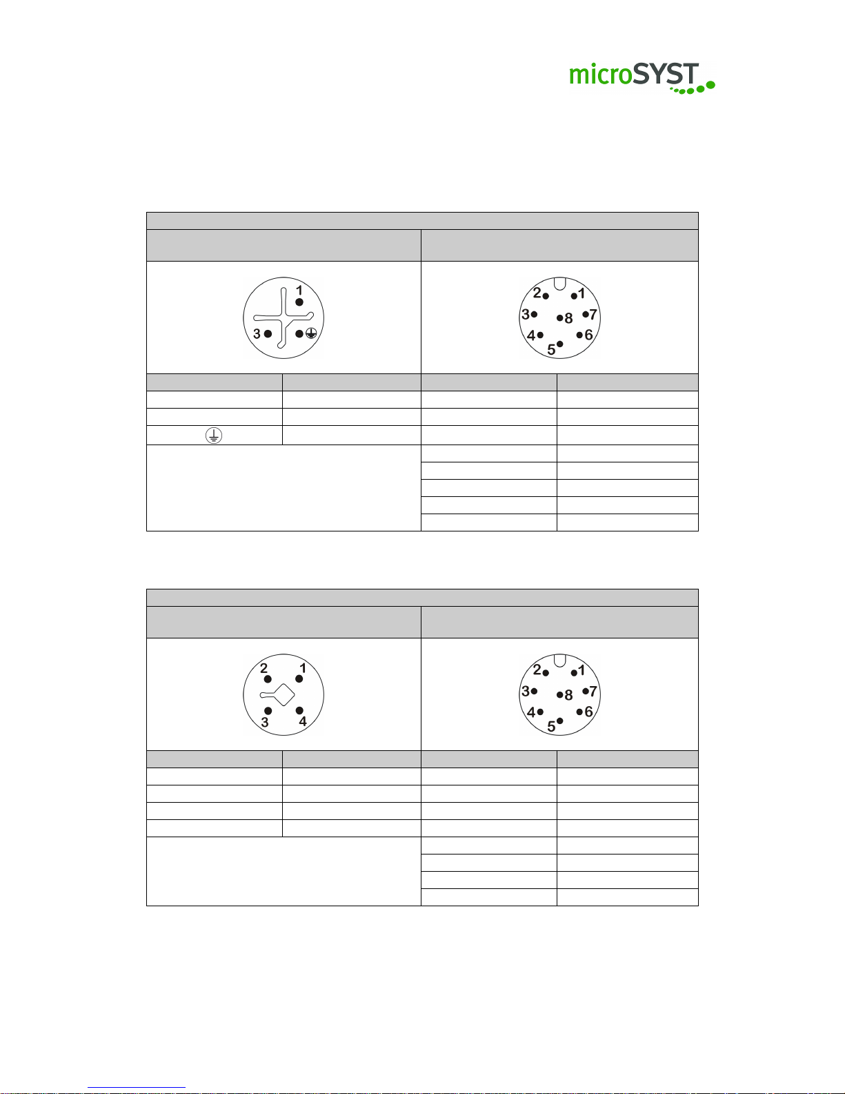
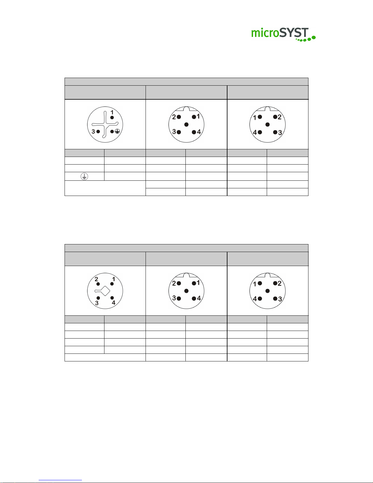
2.2.1 AD converter
AD Converter 230V AC
Power plug 230V AC
M12 / S-Coding
Analog inputs
M12 / A-Coding
PIN Signal PIN Signal
1 L 1 Channel 1 + (voltage)
3 N 2 Channel 1 - (voltage)
PE 3 Channel 2 + (voltage)
4 Channel 2 - (voltage)
5 Channel 3 + (current)
6 Channel 3 - (current)
7 Channel 4 + (current)
8 Channel 4 - (current)
AD Converter 24V DC
Power plug 24V DC
M12 / T-Coding
Analog inputs
M12 / A-Coding
PIN Signal PIN Signal
1 n.c. 1 Channel 1 + (voltage)
2 +24 VDC 2 Channel 1 - (voltage)
3 PE 3 Channel 2 + (voltage)
4 GND 4 Channel 2 - (voltage)
5 Channel 3 + (current)
6 Channel 3 - (current)
7 Channel 4 + (current)
8 Channel 4 - (current)
Page 8
Page 9

2.2.2 Clock
Clock 230V AC
Power plug 230V AC
M12 / S-Coding
Digital IO
M12 / A-Coding
PIN Signal PIN Signal
1 L 1 IN 1
3 N 2 IN 2
PE 3 IN 3
4 IN 4
5 OUT 1
6 OUT 2
7 UDF
8 GND
Clock 24V DC
Power plug 24V DC
M12 / T-Coding
Digital IO
M12 / A-Coding
PIN Signal PIN Signal
1 n.c. 1 IN 1
2 +24 VDC 2 IN 2
3 PE 3 IN 3
4 GND 4 IN 4
5 OUT 1
6 OUT 2
7 UDF
8 GND
Page 9
Page 10
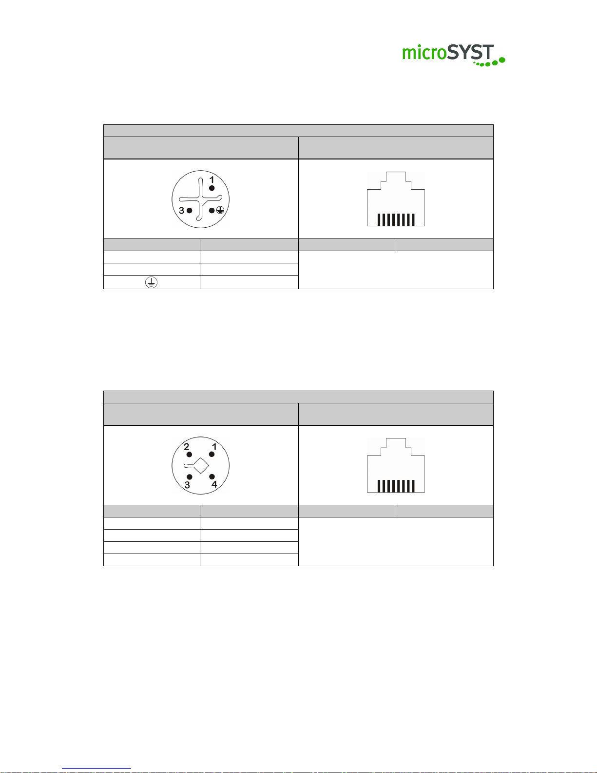
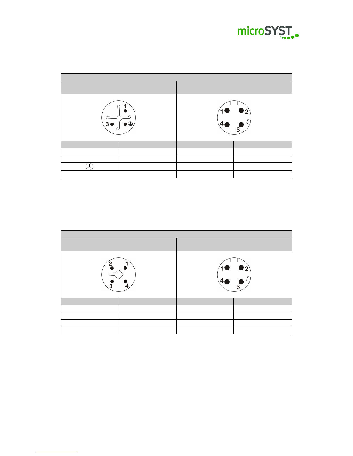
2.2.3 Ethernet
Ethernet 230V AC
Power plug 230V AC
M12 / S-Coding
Ethernet
RJ45
PIN Signal PIN Signal
1 L
3 N
PE
Ethernet 24V DC
Power plug 24V DC
M12 / T-Coding
Ethernet
RJ45
PIN Signal PIN Signal
1 n.c.
2 +24 VDC
3 PE
4 GND
Page 10
Page 11
2.2.4 Digital inputs
Digital Inputs 230V AC
Power plug 230V AC
M12 / S-Coding
Digital inputs
M12 / A-Coding
PIN Signal PIN Signal
1 L 1 Input 1 / Input 8
3 N 2 Input 2 / Input 9
PE 3 Input 3 / Input 10
4 Input 4 / Input 11
5 Input 5 / Input 12
6 Input 6 / Input 13
7 Input 7 / Input 14
8 GND
Digital Inputs 24V DC
Power plug 24V DC
M12 / T-Coding
Digital inputs
M12 / A-Coding
PIN Signal PIN Signal
1 n.c. 1 Input 1 / Input 8
2 +24 VDC 2 Input 2 / Input 9
3 PE 3 Input 3 / Input 10
4 GND 4 Input 4 / Input 11
5 Input 5 / Input 12
6 Input 6 / Input 13
7 Input 7 / Input 14
8 GND
Page 11
Page 12

2.2.5 Pulse counter
Impuls counter 230V AC
Power plug 230V AC
M12 / S-Coding
Impulse inputs
M12 / A-Coding
PIN Signal PIN Signal
1 L 1 Input 1
3 N 2 Input 2
PE 3 n.c.
4 GND
5 n.c.
6 n.c.
7 n.c.
8 Preset / Reset
Impuls counter 24V DC
Power plug 24V DC
M12 / T-Coding
Impulse input
M12 / A-Coding
PIN Signal PIN Signal
1 n.c. 1 Input 1
2 +24 VDC 2 Input 2
3 PE 3 n.c.
4 GND 4 GND
5 n.c.
6 n.c.
7 n.c.
8 Preset / Reset
Page 12
Page 13
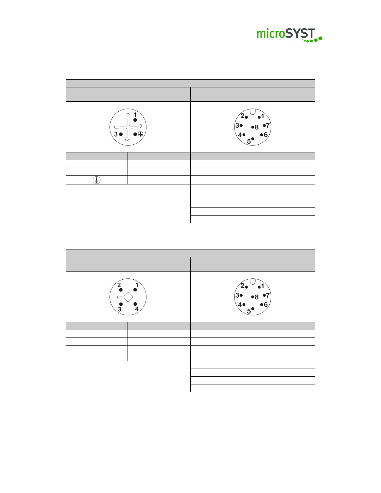
2.2.6 Profibus
Profibus 230V AC
Power plug 230V AC
M12 / S-Coding
Profibus IN
M12 Plug / B-Coding
Profibus OUT
M12 Socket / B-Coding
PIN Signal PIN Signal PIN Signal
1 L 1 +5 VDC 1 +5 VDC
3 N 2 Rx/Tx- (A) 2 Rx/Tx- (A)
PE 3 GND 3 GND
4 Rx/Tx+ (B) 4 Rx/Tx+ (B)
5 Shield 5 Shield
Profibus 24V DC
Power plug 24V DC
M12 / T-Coding
Profibus IN
M12 Plug / B-Coding
Profibus OUT
M12 Socket / B-Coding
PIN Signal PIN Signal PIN Signal
1 n.c. 1 +5 VDC 1 +5 VDC
2 +24 VDC 2 Rx/Tx- (A) 2 Rx/Tx- (A)
3 PE 3 GND 3 GND
4 GND 4 Rx/Tx+ (B) 4 Rx/Tx+ (B)
5 Shield 5 Shield
Page 13
Page 14
2.2.7 Profinet
Profinet 230V AC
Power plug 230V AC
M12 / S-Coding
Profinet IN / OUT
M12 Socket / D-Coding
PIN Signal PIN Signal
1 L 1 TD+
3 N 2 RD+
PE 3 TD-
4 RD-
Profinet 24V DC
Power plug 24V DC
M12 / T-Coding
Profinet IN / OUT
M12 Socket / D-Coding
PIN Signal PIN Signal
1 n.c. 1 TD+
2 +24 VDC 2 RD+
3 PE 3 TD4 GND 4 RD-
Page 14
Page 15

2.2.8 RS485
RS485 230V AC
Power plug 230V AC
M12 / S-Coding
RS485 IN
M12 Plug / B-Coding
RS485 OUT
M12 Socket / B-Coding
PIN Signal PIN Signal PIN Signal
1 L 1 +5 VDC 1 +5 VDC
3 N 2 Rx/Tx- (A) 2 Rx/Tx- (A)
PE 3 GND 3 GND
4 Rx/Tx+ (B) 4 Rx/Tx+ (B)
5 Shield 5 Shield
RS485 24V DC
Power plug 24V DC
M12 / T-Coding
RS485 IN
M12 Plug / B-Coding
RS485 OUT
M12 Socket / B-Coding
PIN Signal PIN Signal PIN Signal
1 n.c. 1 +5 VDC 1 +5 VDC
2 +24 VDC 2 Rx/Tx- (A) 2 Rx/Tx- (A)
3 PE 3 GND 3 GND
4 GND 4 Rx/Tx+ (B) 4 Rx/Tx+ (B)
5 Shield 5 Shield
Page 15
Page 16

2.2.9 Timer
Timer 230V AC
Power plug 230V AC
M12 / S-Coding
Digital IO
M12 / A-Coding
PIN Signal PIN Signal
1 L 1 IN 1
3 N 2 IN 2
PE 3 IN 3
4 IN 4
5 OUT 1
6 OUT 2
7 UDF
8 GND
Timer 24V DC
Power plug 24V DC
M12 / T-Coding
Digital IO
M12 / A-Coding
PIN Signal PIN Signal
1 n.c. 1 IN 1
2 +24 VDC 2 IN 2
3 PE 3 IN 3
4 GND 4 IN 4
5 OUT 1
6 OUT 2
7 UDF
8 GND
Page 16
Page 17

2.3 Switching on / Switching off the device
•
The device is switched on after the supply voltage has been supplied. When starting the
device the switch-on screen depends on the configuration of the device.
• You can switch off the device if you disconnect it from the power supply.
Page 17
Page 18

3 Configuration
Please bear in mind that the devices may not work properly due to an incorrect configuration.
We therefore recommend a backup using the microSYST configuration software 2.x (hereinafter
called “MKS 2.x”) as described below.
3.1 Language settings
To adjust the current language settings, please click on
Extras | language
in the menu bar and
choose the required language.
3.2 Backup of the factory settings
Should you want to change anything please save the current status as backup. Please proceed
as follows:
1.
Please connect the device and read-out the current project from the device. Click on the
button read-out in the MKS 2.x.
2. Then please save the loaded project with File | Save as. . .
3.3 General information
The configuration of the visualisation as well as the used hardware components will solely be
made via the MKS 2.x. The user interface of the microSYST configuration software consists of
three parts:
Project structure, Editor as well as Settings and properties. (Picture 1).
Page 18
Page 19
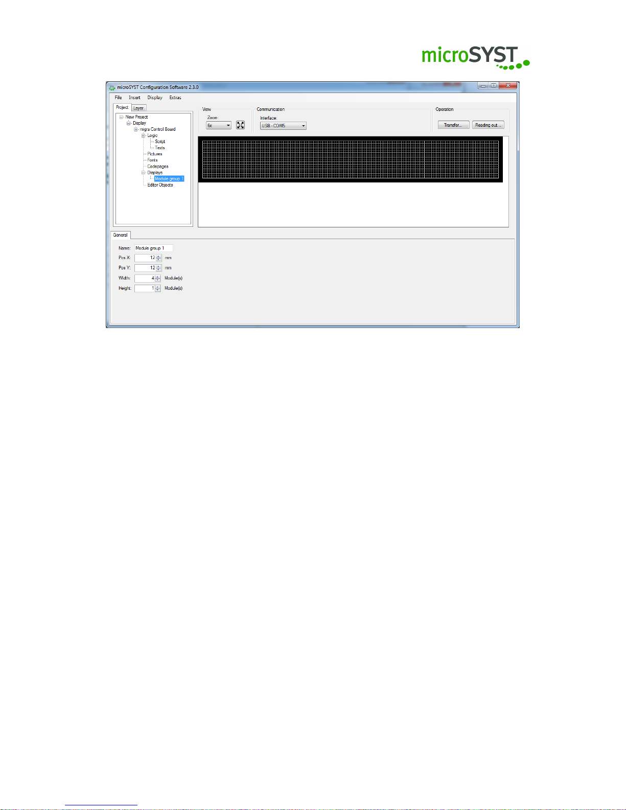
Figure 1: MKS 2.x interface
3.3.1 Project structure and layer view
The project structure can be seen in the upper left window of the user interface. There, the
control board, additional boards, visualisation objects, elements of the editor as well as scripts
and texts are accessible. With the tab layer you can switch to the layer view, there layers can be
shown and hidden or renamed.
3.3.2 Settings and properties
In the lower part, the Settings and properties for the different elements of the project structure
can be found. Each element has various properties. Therefore, click on one of the elements of
the tree structure in order to see the possible settings and properties and to configure it.
3.3.3 Editor
On the right side of the user interface, in the editor, already selected editor elements and
visualisation objects are displayed realistically.
3.4 Reading-out / transmitting / saving the configuration
3.4.1 Reading-out / transmitting
Under Communication you can select from the following interfaces for the performed action:
Page 19
Page 20
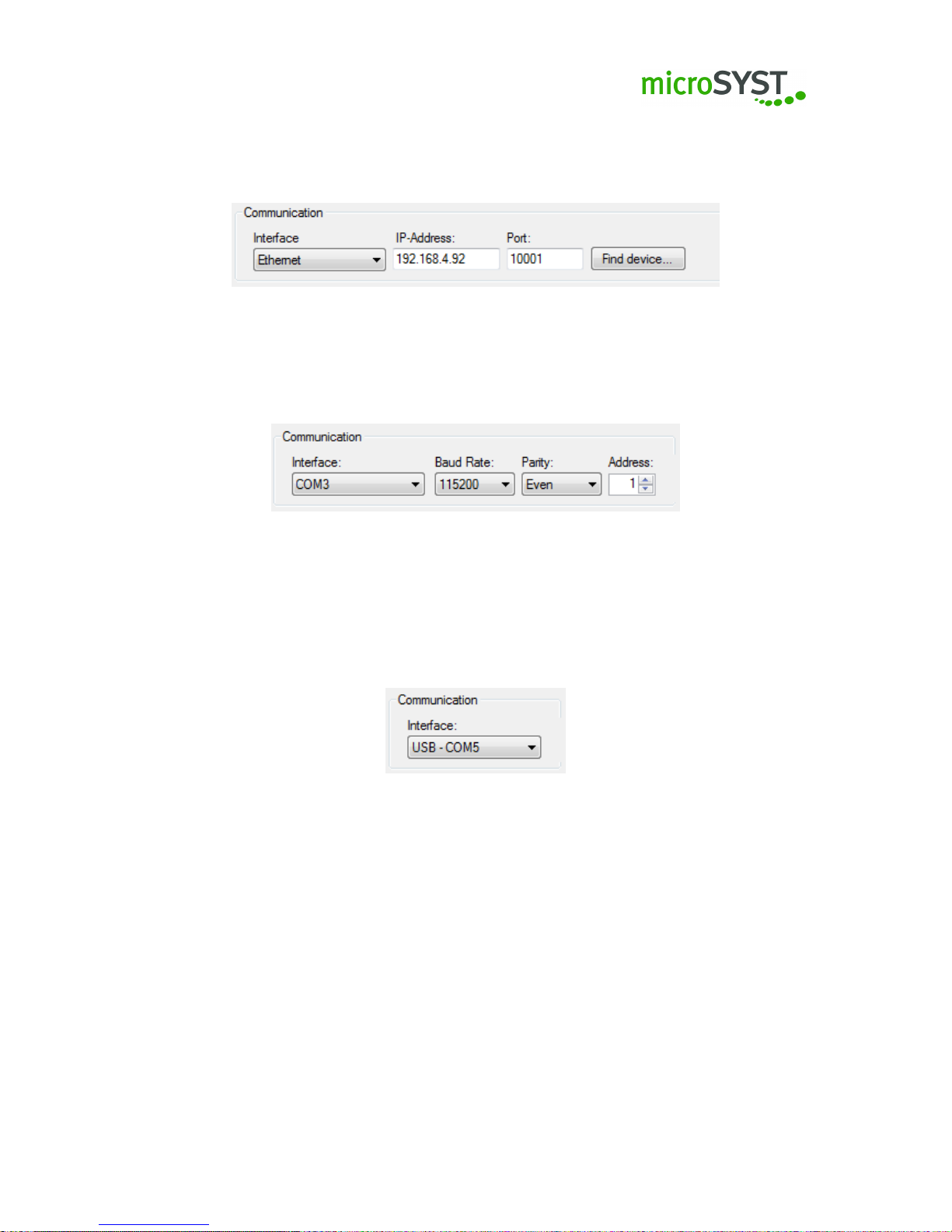
•
Ethernet: Enter the IP address and the port (picture 2). Should you not know the IP
address, please click on searching device and a new dialogue will appear, which shows all
accessible Ethernet participants.
Figure 2: TCP/IP
•
Serial interface (e.g. RS485): Choose the COM port, baud rate and parity for the device
(picture 3). Please also specify the bus address (=address of the control board).
Figure 3: Serial interface
•
USB: Please note that this interface only can be used if the device is connected with the
PC via USB. The device will be logged on with a virtual COM port, then the COM port
will be preselected. Should there be more devices connected , it is possible to choose
between the virtual COM ports. (picture 4)
Figure 4: USB
3.4.2 Saving a project
To save a current project, click on
File | Save as
in the menu bar. Now, you can choose the path
where you want to save the project. If the path is already preselected, you can also just click on
Save in the menu bar.
3.5 Configuration of the IP address
In order to change the IP address of the display, the device has to be available via Ethernet.
Please click on
Display|Configure interface. . .
in the menu bar in order to open the configure
Page 20
Page 21
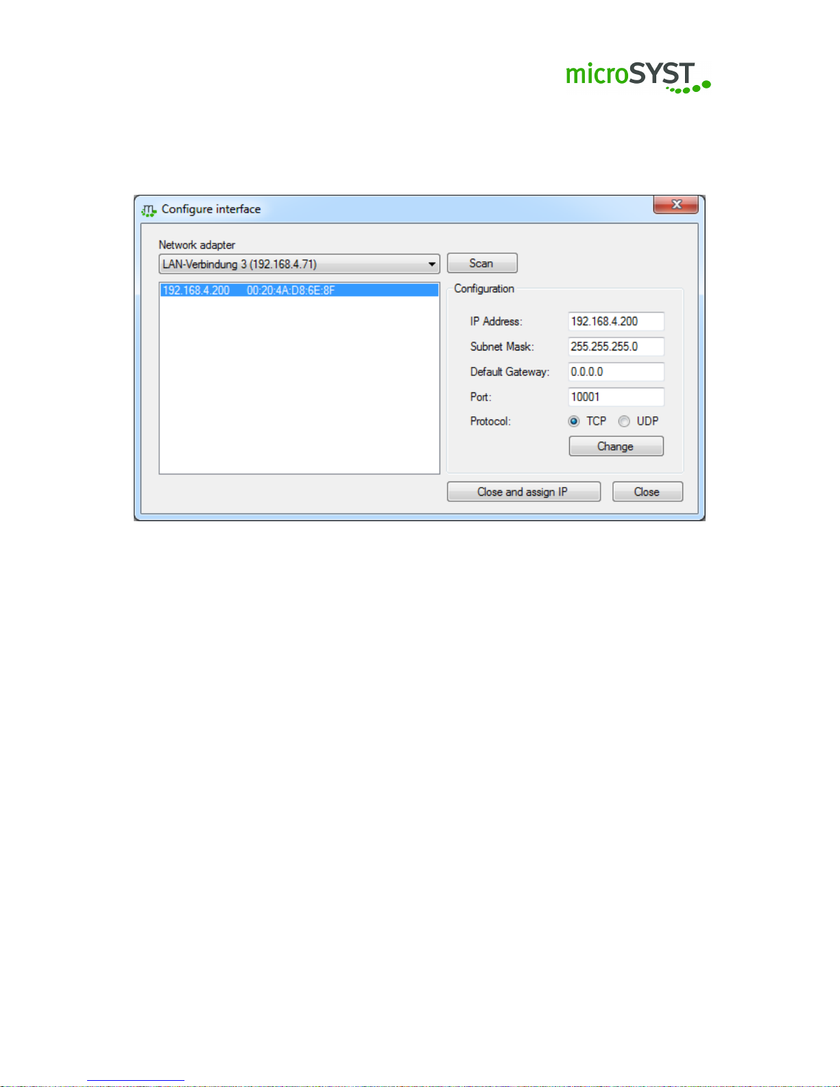
interface dialogue (picture 5) and select the IP address to be changed from the list. Adjust the IP
address under configuration | IP address accordingly and click on Change for the acceptation of
the IP address. If you close the dialogue box with Close and assign IP the new IP address will
be entered automatically under communication.
Figure 5: Configure interface
3.6 Configuration of the hardware components
Please note that each device has a basic configuration. Do you want to change it afterwards,
please use the MKS 2.x. For more information please follow the instructions of each component.
Note: Please note that only the components used by microSYST can be configured.
Components / additional boards
The components / additional boards are forming the microSYST Peripheral Bus System (MPB)
and can be combined or modified depending on cutomer’s requirements. With the MKS 2.x, the
Control Board and the individual components can be configured for displaying the desired data.
In the following, the features, options and possible settings of the control board and the components will be described in detail.
Note:
For each of the components / additional boards you can find the Name, the Address and
the Poll cycle under Settings and Properties and General.
Page 21
Page 22
3.6.1 Control board S1X4
The control board will be inserted automatically when creating a new project. By clicking on
the control board in the project structure the Settings and Properties of this component will be
displayed.
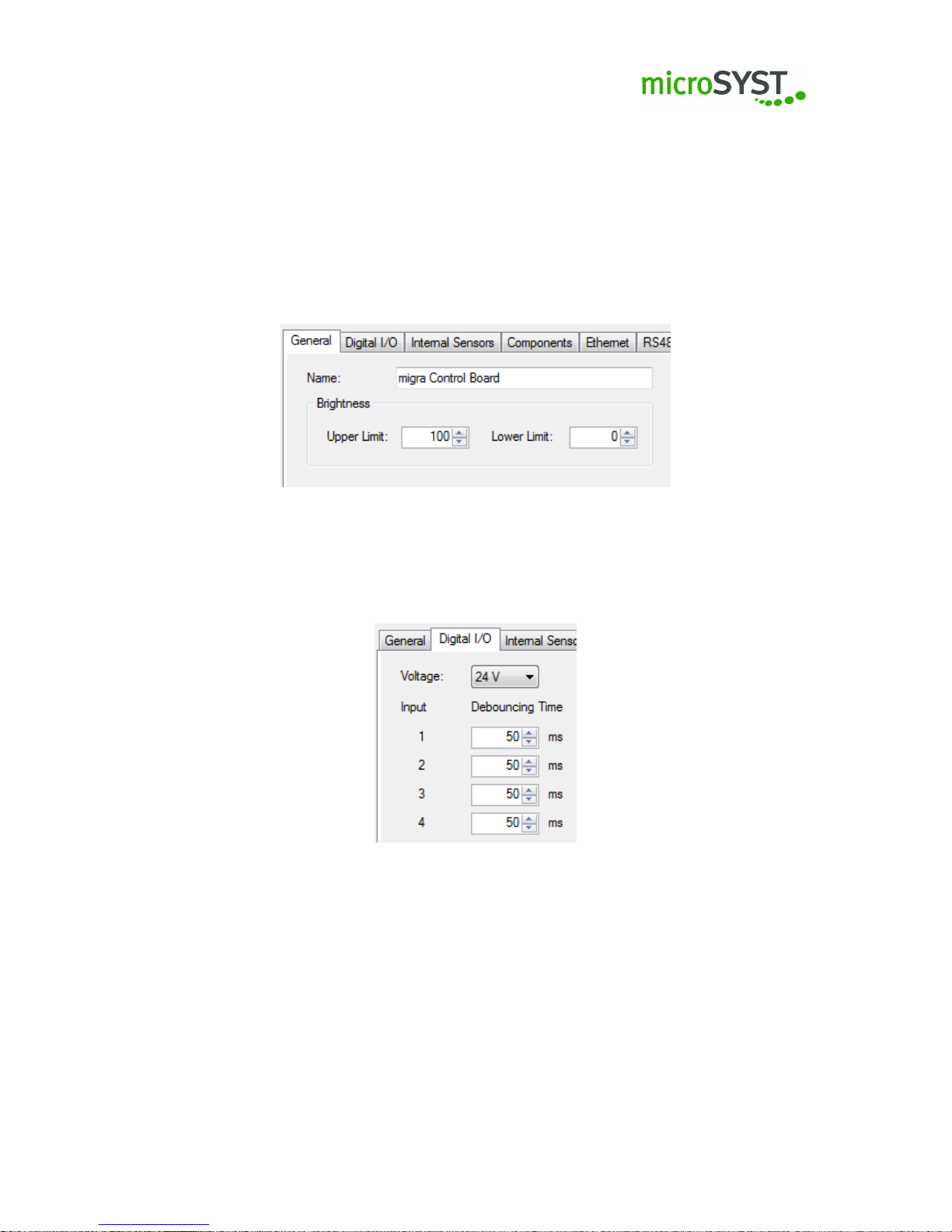
Under Settings and Properties and General (picture 6) you can change a component’s name
in the project. Please confirm it with the enter key. The new name will appear in the upper left
corner of the project structure. You can adjust the maximum brightness of the display here as
well.
Figure 6: Tab General
The control board has four inputs in total (e.g. for using switch inputs). The tab Digital I/O (picture
7) is for adjusting the debouncing time for each input as well as the input level of all inputs.
Figure 7: Tab Digital I/O
You can operate the control board in a Master or Slave mode under the tab Internal Sensors
(picture 8) . This setting is important if multiple control boards are sharing one sensor (e.g. brightness, humidity sensor etc.). The tab Internal Sensors is preconfigured by default and must not
be changed.
Page 22
Page 23
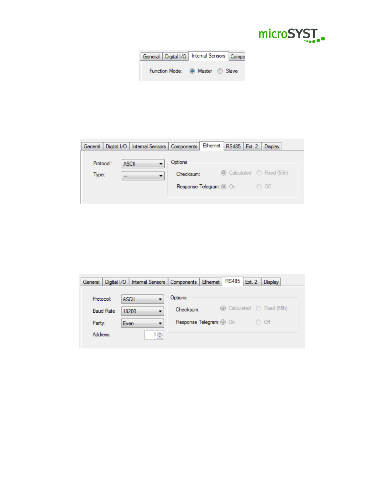
Figure 8: Tab internal sensor
You can configure the Ethernet interface under Ethernet (picture 9). The default protocol is ASCII
and will be described in this manual.
Figure 9: Tab Ethernet
The settings for the RS485 interface can be found under the tab RS485 (picture 10). The default
protocol is ASCII and will be described in this manual.
In addition to this you can set baud rate, parity and the RS485 bus address of the control board.
Figure 10: Tab RS485
Under the tab Ext.2 (picture 11) you can configure the external interface 2. The default protocol
is ASCII and will be described in this manual.
This interface can be configured and used under Extern 2 as RS232 or RS485. If set to RS485,
the RS485 bus address refers to the address in tab RS485. In both settings you can configure
the baud rate and parity of the interface.
Page 23
Page 24
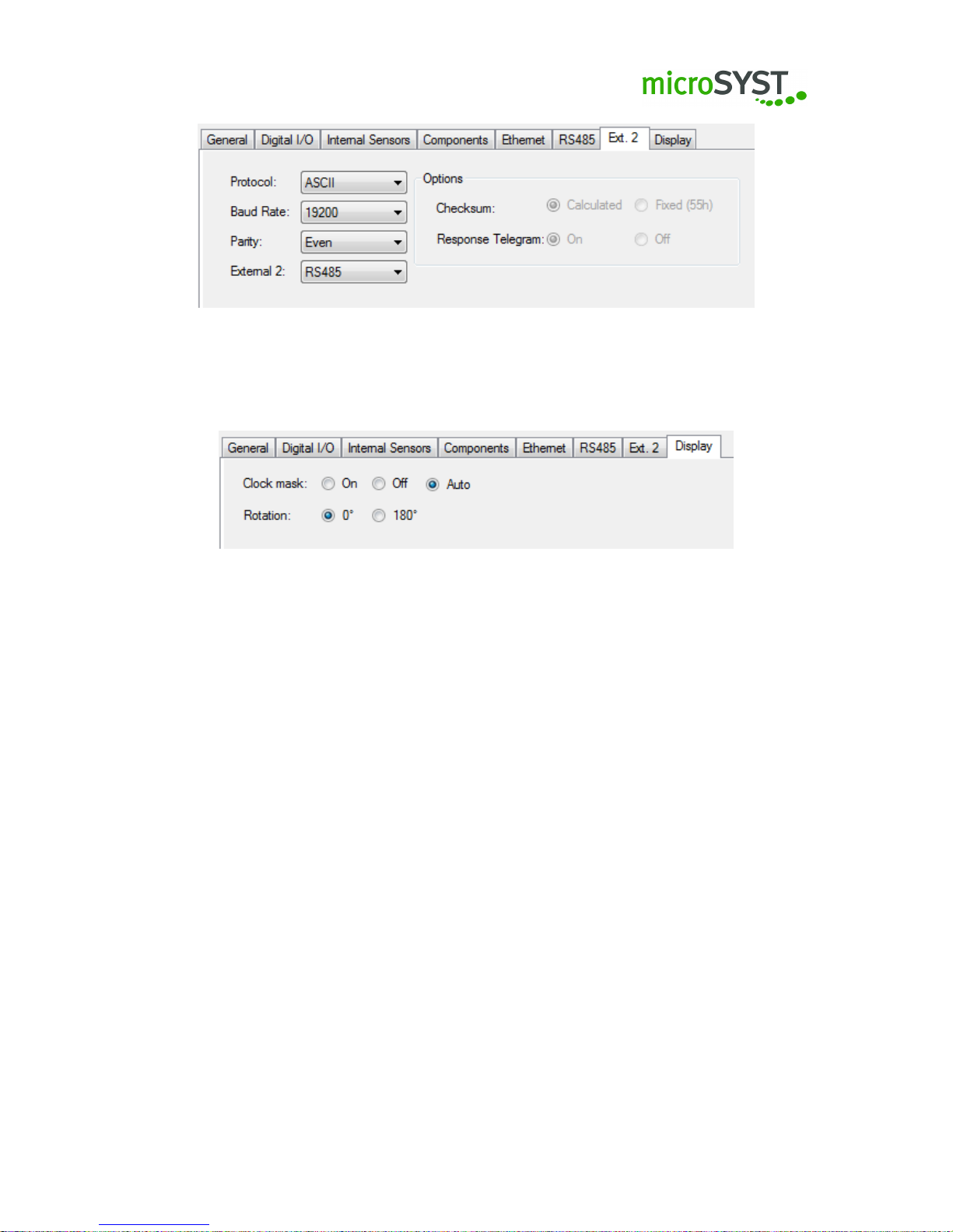
Figure 11: Tab Ext.2
The tab Display (picture 12) can be used to adjust the display specifications.
Figure 12: tab display
3.6.2 AD converter
The AD converter enables you to convert physical measuring units (length, mass, time) into
digits. It has two channels for power and two channels for voltage.
Important:
Please note that each of the four channels has to be activated before usage, so it
can supply a value.
3.6.2.1 Channel 1 / Channel 2 - Voltage
Enable / disable the channel under Use (picture 13).
The accuracy of the AD converter can be determined with specifying the resolution and the
average value under Accuracy. The resolution specifies the number of areas that are divided in
sectors with a voltage ranging from -10 bis +10 V. With regard to the average value information
on the last measured voltage level is gathered and thus the average value, which shall be used
for stabilising the display values, is calculated.
The upper and the lower limit, which the display value refers to, can be specified with the threshold
value. If then the device value has exceeded / fallen below the upper or lower limit, it is possible
to react individually.
The measuring straight is defined by two points. The measuring straight determines which value
is represented when a voltage is applied.
Page 24
Page 25

Figure 13: tab Channel 1/Channel 2
3.6.2.2 Channel 3 / Channel 4 - power
Enable / disable the channel under Use (picture 14).
The accuracy of the AD converter can be determined with specifying the resolution and the
average value under Accuracy. The resolution specifies the number of areas that are divided
in sectors with a current ranging from -20 mA bis +20 mA. With regard to the average value
information on the last measured current is gathered and thus the average value, which shall be
used for stabilising the display values, is calculated.
The upper and the lower limit, which the display value refers to, can be specified with the threshold
value. If then the device value has exceeded / fallen below the upper or lower limit, it is possible
to react individually.
The measuring straight is defined by two points.The measuring straight determines which value
is represented when a current is applied.
Figure 14: tab Channel 3/Channel 4
3.6.3 BCD / IO
The operating mode of this component can be adjusted under Function (picture 15). You can
choose between different options:
•
Digital input: delivers the current input level (depending on high/low mode). Additionally, high edge results will be reported once. In order to be able to evaluate the results
meaningfully, the poll cycle time should be set to at least 100 ms.
• BCD Parallel, BCD Multiplex: the inputs are run in BCD mode(=method)
Page 25
Page 26

Figure 15: tab Function
When enabled, the special characters extend the numerics by the following alphabectical char-
acters (picture 16): H, E, L, P, (space), -.
BCD parallel: You can select the number of decimal places from 1 to 4.
BCD Multiplex: You can select the number of decimal places from 1 to 6.
Figure 16: Special Characters
The inputs can be adjusted under Inputs (picture 17).
Name: shows the name of each input.
Logic: If invert is activated you can invert the high / low level at the input.
Pull up: Pull up is a resistor which will be applied to the internal supply voltage in order to read in
a high signal at an open input.
Pull down: Pull down is a resistor which will be applied to the internal ground in order to read in
a low signal at an open input.
Debouncing cycles: adjustable time for debouncing the inputs for precisely identifying (=bouncefree) any change of state.
Figure 17: tab Inputs
Page 26
Page 27

3.6.4 Pulse counter
Under operating mode you can select from the following options:
• Pulse counter
• Pulse interval
• Impulses per time
• Interval counter
• Incremental Decoder
• Incremental Decoder IDX Reset
• Incremental Decoder Velocity
In the following, the above mentioned operating modes will be explained in detail.
Important:
Please note that there are different inputs depending on the operating mode (4
inputs in total). Input 1, 2, Reset and Incremental Decoder Input (Inc.Dec.Input). You can adjust
these inputs under the tab Inputs as soon as you have chosen the operating mode (please see
operating modes-mode).
Note:
The operating modes pulse counter, pulse interval, impulses per time and interval counter
generate two values:
Pulse counter value 1: counter value Pulse counter value 2: Status value
The operating modes Incremental Decoder, Incremental Decoder IDX Reset, Incremental Decoder Velocity generate two values:
Pulse counter value 1 – Incremental counter value
Pulse counter value 2 – IDX counter value (rotations)
Page 27
Page 28

3.6.4.1 Operating mode - Pulse counter
The pulse counter counts pulses up and down at both inputs. Thereby the settings of input 2 can
determine the counting direction of input 1 (picture 18).
Under Options - min. / max. you can find several options concerning the settings of your counter
when reaching the minimum / maximum value:
• Ignore: Counter continues to count (32 bit)
• Stop counter: The counter stops counting after reaching the minimum / maximum value
•
Counter overflow through zero: The counter restarts to count from zero after exceeding the
min. / max. value
•
Overflow through minimum / maximum value: The counter restarts to count from the max
value after the min value has been reached. After exceeding the maximum value, the
counter restarts from the minimum value.
As soon as you have chosen the required function you can specify the upper and lower limit, if
needed. After reaching the upper / lower limit a bit in the status value will be set (please see list
above).
Furthermore, you can determine the maximum value and the minimum value of the counter
regarding the overflow and stopping options.
A bit will be set in the status value after the expiry of the adjusted signal timeout period. With
each pulse the timeout counter will be set to 0.
Figure 18: Pulse counter
Under Inputs (picture 19) you can adjust the inputs 1 and 2 and under Reset you can adjust the
level, cut-off frequency (= filter for bouncing signals) and counting direction as well as activation,
debouncing filter and preset value (= start value of the counter after reset) via selection fields.
Note:
If the level has been adjusted to Pull up a pull-up resistor will be switched to 5 V, the
maximum pulse repetition frequency is 100 Hz (minimal pulse duration 5 ms).
Page 28
Page 29

Figure 19: tab Inputs
3.6.4.2 Operating mode - Pulse interval
In that mode the time between two edges is measured.
Under Options - min. / max. (Abbildung 20) you can find several options concerning the settings
of your counter when reaching the min. / max. value:
• Ignore: Counter continues to count (32 bit)
• Stop counter: The counter stops counting after reaching the min. / max. value.
As soon as you have chosen the required function, you can specify the upper and lower limit.
After reaching the upper / lower limit a bit in the status value will be set (please see list above).
Furthermore, you determine the maximum value and the minimum value of the counter regarding
the stopping options.
The average of up to 30 measured values can be calculated with the average value.
A bit will be set in the status value after expiry of the adjusted signal timeout period. With each
pulse the timeout counter will be set to 0. The result will be multiplied with the resolution (unit
per digit).
Under inputs you can adjust the input 1 via selection fields:
Level, cut-off frequency (picture 21).
Note:
If the level has been adjusted to Pull up a pull-up resistor will be switched to 5 V, the
maximum pulse repetition frequency is 100 Hz (minimal pulse duration 5 ms).
Page 29
Page 30

Figure 20: Pulse interval
Figure 21: tab Inputs
3.6.4.3 Operating mode - Pulses per time
It is possible to display the number of pulses per selected time unit (picture 22).
Under Options - min. / max. you can find several options concerning the settings of your counter
when reaching the min./max value:
• Ignore: Counter continues to count (32 bit)
• Stop counter: The counter stops counting after reaching the min. / max. value
As soon as you have chosen the required function, you can specify the upper and lower limit.
After reaching the upper / lower limit a bit in the status value will be set (please see list above).
Furthermore, you determine the maximum value and the minimum value of the counter regarding
the overflow and the stopping options.
The average of up to 30 measured values can be calculated with the average value.
Page 30
Page 31

A bit will be set in the status value after expiry of the adjusted signal timeout period. With each
pulse the timeout counter will be set to 0.
Under time unit you can determine the time frame in ms in which the incoming pulses will be
counted.
Figure 22: Impulses per time
Under Inputs you can adjust the input 1 via selection fields: Level, cut-Off Frequency (picture
23).
Figure 23: tab Inputs
Note:
If the level has been adjusted to Pull up a pull-up resistor will be switched to 5 V, the
maximum pulse repetition frequency is 100 Hz (minimal pulse duration 5 ms).
3.6.4.4 Operating mode - Interval counter
In that mode it is counted upwards and downwards in the interval of the time unit.
Under Options - min. / max. (picture 24) you can find several options concerning the settings of
your counter when reaching the min. / max. value:
Page 31
Page 32

• Ignore: Counter continues to count (32 bit)
• Stop counter: The counter stops counting after reaching the min. / max. value
•
Counter overflow through zero: The counter restarts to count from zero after exceeding the
min. / max. value
•
Overflow through min. / max. value: The counter restarts to count from the max value after
the min value has been reached. After exceeding the max. value, the counter restarts from
the min. value.
As soon as you have chosen the required function, you can specify the upper and lower limit.
After reaching the upper / lower limit a bit in the status value will be set (please see list above).
Furthermore, you determine the maximum value and the minimum value of the counter regarding
the overflow and the stopping options.
Under time unit you can adjust the interval in ms. Furthermore, please select the counting
direction up or down.
Figure 24: Interval counter
Under inputs you can adjust Reset via selection fields:
Level, control, debouncing filter and preset value (= start value of the counter after reset) (picture
25).
Note:
If the level has been adjusted to Pull up a pull-up resistor will be switched to 5 V, the
maximum pulse repetition frequency is 100 Hz (minimal pulse duration 5 ms).
Page 32
Page 33

Figure 25: tab Inputs
3.6.4.5 Operating mode - Incremental Decoder
Incremental (quadrature) decoder, 32 Bit quadrature register. Additionally, 32 bit counter register
of the Dx signal (complete rotation) both upwards and downwards (picture 26).
Figure 26: Incremental decoder
Under inputs and Inc.Dec.input you can adjust the filter (picture 27). For each incremental input
Dx, phA, phB you have the possibility to choose between 1 to 63 (6 bit). The minimum pulse
width is
value+1
48
M H z.
All incremental inputs can be inverted by marking:
• Invert Dx
• Invert phB
• Invert phA
Under Reset you can adjust level, control, debouncing filter and preset value (= start value of the
counter after reset) via selection fields.
Note:
If the level has been adjusted to Pull up a pull-up resistor will be switched to 5 V, the
maximum pulse repetition frequency is 100 Hz (minimal pulse duration 5 ms).
Page 33
Page 34

Figure 27: Inputs incremental decoder
3.6.4.6 Operating mode - Incremental Decoder IDX Reset
Incremental (quadrature) decoder, 16 Bit quadrature register. Additionally, 16 bit counter register
of the Dx signal (complete rotation) both upwards and downwards (picture 28). The quadrature
register will be deleted after each Dx pulse. So the quadrature register shows the position of the
encoder in relation to Dx.
Figure 28: Incremental decoder IDX Reset
Under inputs and Inc.Dec.input you can adjust the filter (picture 29). For all Incremental inputs
Dx, phA, phB you have the possibility to choose between 1 to 63 (6 bit). The minimum pulse
width is
value+1
48
M H z.
All incremental inputs can be inverted by marking:
• Invert Dx
• Invert phB
• Invert phA
Under Reset you can adjust level, control, debouncing filter and preset value (= start value of the
counter after reset) via selection fields.
Note:
If the level has been adjusted to Pull up a pull-up resistor will be switched to 5 V, the
maximum pulse repetition frequency is 100 Hz (minimal pulse duration 5 ms).
Page 34
Page 35

Figure 29: Inputs incremental decoder IDX Reset
3.6.4.7 Operating mode - Incremental Decoder velocity
In that operating mode you can see the number of increments per selected time unit (picture 30).
Depending on the direction of rotation they can be positive or negative.
The average of up to 30 measured values can be calculated under Options. Under Time unit
you can determine the timeframe in ms in which the incoming pulses will be counted.
Figure 30: Incremental decoder velocity
Under Inputs and Inc.Dec.input you can adjust the filter (picture 31). For all Incremental inputs
Dx, phA, phB you have the possibility to choose from 1 to 63 (6 bit). The minimum pulse width is
value+1
48
M H z.
All incremental inputs can be inverted by marking:
• Invert Dx
• Invert phB
• Invert phA
Page 35
Page 36

Figure 31: Inputs incremental decoder velocity
3.6.5 RS / RTC
With the RS/RTC component you can receive telegrams and adjust it to deliver and to display
the required values.
Additionally, the exact time via Real Time Clock (RTC) can be displayed.
Time out, baud rate and parity can be adjusted under the tab RS232 Settings respectively RS485
Settings (picture 32).
Figure 32: tab RS232 settings
Additionally, you can find stop bits, data bits and mode under RS485 Settings (picture 33). You
can choose between RS485, RS422 and RS232. The bus termination can be en- or disabled.
You can configure the telegram parts you received from a connected device (e.g. from scales) and
the telegram parts that need to be processed with the RS/RTC component under RS485-Telegram
respectively RS232-Telegram (picture 34).
Page 36
Page 37

Figure 33: tab RS485 settings
Figure 34: tab RS485 - Telegram
3.6.5.1 Inserting a telegram part
To insert a new telegram part, click on New. . . under the tab RS485 / RS232 Telegram (picture
34). A new dialogue appears (picture 35) where you can create a new telegram part. Now, you
can define the name and the data type to be created.
Note:
• Integer: a whole-numbered value between 1 - 4 bytes which can be unsigned or signed.
•
String: a string of characters which consists of a byte sequence which will be used in a
different coding (e.g. UTF8, CP1252, etc. . . . ) It has a defined length.
•
Dynamic: a string of characters which consists of a byte sequence which will be used in a
different coding (e.g. UTF8, CP1252, etc. . . . )
It has an undefined length.
Please confirm your selection with the button Create. The different options regarding the individual
Page 37
Page 38

Figure 35: New Telegram Part
data types can be changed and adjusted in the detail view of each data type. By one click on the
data type in the list the detail view appears on the right side (please see the following chapters
detail view integer, detail view string, detail view dynamic).
3.6.5.2 Detail view integer
Figure 36: Integer settings
• Name:
The telegram part’s name.
• Usage:
Length specifications: The stated length specifications bytes are used for specifying the
length of the following bytes.
Delta: The entered delta value will be added to the length specification.
Conformity: A hexadecimal value can be specified here. This value has to be conform with
the value in the data type position in the telegram. The hexadecimal value has to contain
as many bytes as configured by the type.
Undefined: The numeric value has no defined significance for the evaluation.
• Data type:
Page 38
Page 39

Type You can choose between different types. The data type determines the number of
the following bytes. Unsigned data types are marked with uintX and signed data types are
marked with intX, the X shows the number of bits.
Byte order As soon as the selection is bigger than 8 bits, the byte order option will be
activated. This option is important for a correct interpretation of the decimal value. MSB –
Higher-value byte first LSB – Lower-value byte first
3.6.5.3 Detail view string
Figure 37: String settings
• Name:
The telegram part’s name.
• Usage:
Length specifications: The following ASCII characters are used for the length specification
of following telegram entries (bytes). Additionally, the string option has to be marked with
“process as value”. With this option, all existing decimal numbers will be converted into an
integer value.
Delta: The entered delta value will be added to the converted integer value which acts as
a length specification.
Undefined: The ASCII characters have no specific meaning for the evaluation.
• String length:
Fixed: You can enter the number of following ASCII characters.
Conformity: Here, you can enter an ASCII character string (10 characters max.) that has
to be conform with the character string in the telegram.
Preceding length specification: A preceding telegram entry has to be marked with “length
specifications”. Then the ASCII character string’s length will be defined.
Page 39
Page 40

• String options
Decimal: The ASCII character string may only contain the following characters: 0 1 2 3 4 5
6 7 8 9
Hexadecimal: The ASCII character string may only contain the following characters: 0 1 2
3 4 5 6 7 8 9 a b c d e f A B C D E F
Alphabetical: The ASCII character string may only contain the following characters: A – Z,
a - z
Alphanumeric: The ASCII character string may only contain the following characters: A –
Z, a – z, 0 – 9
Displayable characters: The ASCII character string may only contain the following characters: space, ! " # $ % & ’ ( ) * + , - . / : ; < = > ? @ [ ] ˆ _ ‘ { | } ~ A – Z, a – z, 0 –
9
Process as value See Application - Length specifications
3.6.5.4 Dynamic detail view
Figure 38: Dynamic settings
• Name:
The telegram part’s name.
• Synchronisation
The dynamic data type requires a preceding and a following telegram entry with the
application “Conformity” as a fixed point. The option last hit can be set if the preceding
fixed point should occur multiple times in the dynamic part. If the preceding fixed point is
clearly defined and does not occur in the dynamic part, the option first hit is used.
• String options
Decimal: The ASCII character string may only contain the following characters: 0 1 2 3 4 5
6 7 8 9
Page 40
Page 41

Hexadecimal: The ASCII character string may only contain the following characters: 0 1 2
3 4 5 6 7 8 9 a b c d e f A B C D E F
Alphabetical: The ASCII character string may only contain the following characters: A – Z,
a - z
Alphanumeric: The ASCII character string may only contain the following characters: A –
Z, a – z, 0 – 9
Displayable characters: The ASCII character string may only contain the following characters: space, ! " # $ % & ’ ( ) * + , - . / : ; < = > ? @ [ ] ˆ _ ‘ { | } ~ A – Z, a – z, 0 –
9
Process as value See Detail View for String - Application - Length specifications
3.6.6 Deleting a telegram part
If you want to delete an existing telegram part in the telegram chart, select the relevant telegram
part and click on Delete.
3.6.7 Moving a telegram part
If you want to move an existing telegram part in the telegram chart up or down, select it and click
on Up or Down.
Important: Special features of the telegram structure:
1.
The telegram structure may never contain a dynamic data type and a telegram entry with
application length specification at the same time!
2. Two dynamic data types may never be inserted successively.
After having set up the telegram parts correctly, you can activate the corresponding line under
Process data in order to use the data (picture 39).
Figure 39: Telegrams
3.6.7.1 Real Time Clock
You can also use the Real Time Clock. This feature must be activated (picture 40).
Page 41
Page 42

Figure 40: RTC tab
Under settings you can select your preferred time zone as well as the display format from already
pre-selected format strings or you can also enter formats which you require.
Important: Please use the placeholders available in the formatting string under settings :
Page 42
Page 43

Placeholder Description
%a Short name of the weekday. Depending on the location
%A Full name of the weekday. Depending on the location.
%b Short name of the month. Depending on the location.
%B Full name of the month. Depending on the location.
%c The structure of date and time depends on the location.
%C Indication of the century. Integer values from 00 to 99.
%d Day of the month written with two digits from 01 to 31.
%D as %m/%d/%y
%e
Day of the month written as decimal value. Single-digit values have a space character put
in front. Values from ' 1' to '31'.
%g as %G, but without century.
%G
The four-digit year complies with the ISO specification. (see %V). The same format and the
same value as %Y. Specification: if the ISO week is the previous or the following year the
current year will be used.
%h as %b
%H 24-hour format from 00 to 23.
%I 12-hour format from 00 to 12.
%j Day of the year as value from 001 to 366.
%K If the current date is a special day the name of the special day will be displayed.
%m The month as value from 01 to 12.
%M Minute as decimal value.
%n New line.
%p Either 'am' or 'pm' depending on the location.
%r Time in a.m. or p.m. format.
%R Time in 24-hour format.
%S Seconds as decimal value.
%t Tabulator
%T Current time as %H:%M:%S
%u Day of the week as decimal value from 1 to 7. Monday starts with one.
%U
Number of the week of the current year as decimal value. Starting with the first sunday as
first day of the first week.
%V
Calendar week according to ISO 8601:1988 of the current year. Written with the decimal
value from 01 bis 53. The first week has at least four days in the current year. The week
starts with monday. Use %G or %g for the year.
%w Weekday as decimal value. Sunday is 0.
%W
Number of the week of the current year starting with the first monday as the first day of the
first week.
%x The diplayed date depends on the location.
%X The displayed time depends on the location.
%y The year as two-digit value from 00 to 99.
%Y The year as four-digit value incl. century.
%Z Name or short name of the time zone.
%% % character.
Page 43
Page 44

With special days (picture 41) you can determine specific days which are not standard (e.g. com-
pany holidays, month-end, public holidays etc.) You can either indicate individual days or a
specific period (from date_x to date_y) and enter an individual name. Please click on add in
order to see this day or period in your list. With a click on delete you can remove the previously
selected entry.
Figure 41: Special days
Public holidays can be displayed from year X - year Y (picture 42). To do so, please select
the requested public holidays and add them with OK to the special day list. You have also
the possibility to select a number of days. Click on one day and select the requested days by
dragging with the mouse or press the Strg-key and select the requested days by a click on the
required days.
Figure 42: Selecting public holidays
Page 44
Page 45

3.6.8 Sound board
Under the tab MP3’s you can add your required songs with the button Add (picture 43).
Figure 43: tab MP3’s
Important:
Please note that the memory of the sound board ist limited to 15,9 MB. It is useful to
use only small MP3 files as the transfer will probably takes some time.
You can also delete the selected music tracks at any time or move them up or down by one
position.
Under the tab playlists (picture 44) you can add a playlist or delete it.
Figure 44: tab playlists
Important: Please note that the name of the playlist cannot be changed.
You can find all your uploaded music tracks under MP3 files. Every title may only exist once.
You can add the tracks with >> to the previously selected playlist or you can remove them with
<<. On the playlist you can move up or down the requested tracks.
3.6.9 Profibus
Under Options (picture 45) you can adjust the Profibus DP slave address in the range from 1 to
126. Please select empty data if you want all values to be set to 0 and the strings to be set to
empty after a break in the Profibus DP communication.
Page 45
Page 46

Figure 45: tab Option
Under the tab Data (picture 46) you can configure the received data and the data to be processed
with the Profibus component. Under Length you can see the number of bytes of the added data
part. The number of output bytes shows you how many bytes you have already assigned.
Figure 46: tab data
3.6.9.1 Inserting a data part
To insert a new data part, click on New. . . under the tab data (picture 46). A new dialogue
appears (picture 47) where you can create a data part. You can select the name and the required
data type.
Figure 47: Inserting a data part
Note:
Page 46
Page 47

• Integer: an integer value between 1 - 4 byte, can be unsigned or signed.
•
String: a string of characters which consists of a byte sequence which will be used in a
different coding (e.g. UTF8, CP1252, etc. . . . ) It has a defined length.
Confirm the selected data type with the button Create.
The different options regarding the individual data types can be changed and adjusted in the
detail view of each data type. By one click on the data type in the list the detail view appears on
the right side (please see the following chapters settings integer, settings string).
3.6.9.2 Integer settings
Figure 48: Integer settings
• Name:
Name for the telegram part.
• Data type:
Type You can choose different types. The data type defines the number of bytes. Unsigned
data types are marked with uintX and signed data types with intX whereby the X describes
the number of bits.
Byte order As soon as the selection is higher than 8 bit the option for the byte order will be
activated. This is important in order to correctly interpret the decimal value.
MSB – Higher-value byte first LSB – Lower byte first
3.6.9.3 String settings
Figure 49: String settings
Page 47
Page 48

• Name:
Name for the telegram part.
• Number of characters:
Number of characters in the string.
3.6.9.4 Deleting a data part
If you want to delete an already existing data part in the data sheet, select the required data part
and click on delete.
3.6.9.5 Moving a data part
If you want to move an already existing data part in the data sheet up or down, select the required
data part and click on Up or Down.
By activating Process data (picture 50) you select the data wich shall be used. If you do not want
to use several fields in the Profibus data, you can ignore them by creating the data part but by
not activating Process data.
Figure 50: Data
Page 48
Page 49

3.6.10 Profinet
With regard to the Profinet component, the configuration of the received data and the data to be
processed can be found in the previous chapter Profibus|Inserting a data part.
3.6.10.1 PROFIenergy
Under the tab PROFIenergy (picture 51) you can define several pause modes. Both the minimum
pause time and the corresponding maximum electrical power consumption of the device have to
be specified. (“OW” means that the power consumption is unkown)
Figure 51: tab PROFIenergy
In the line Ready to operate the maximum power consumption for the normal operating mode
Ready-To-Operate will be entered.
Important:
These settings are device-specific and will normally be made by microSYST. The
Profinet component provides the current PE mode. The reaction of the display to the different
PE modes is made with scripting (e.g. darkening or switching-off the display).
3.6.10.2 Project engineering of the microSYST MPB Profinet interface in Siemens TIA
portal (V14)
1.
Create or open a TIA project which contains a PLC / controller with Profinet interface
(PN-Controller).
Note:
Please check if the current GSD file for the device (GSDML-V2.xx-MICROSYST-
MIFACEPNMPB-xxxxxxxx.XML) has been installed. You can find the file on
www.microsyst.de and install it under the menu item Options / Manage general
station description files (GSD) in the TIA portal.
2.
Please double-click in the project tree on Devices & networks to open the Network view (picture 52)and select the entry Other field devices/PROFINET IO/I/O/microSYST/Miface/PNIO-
MPB/MifacePnMpb-DAP3 in the hardware catalog.
Page 49
Page 50

Figure 52: Network view and hardware catalog
3. Drag MifacePnMpb-DAP3 into the network view (picture 53).
Figure 53: Inserting MifacePnMpb-DAP3
4.
Connect MifacePnMpb-DAP3 via PROFINET IO-System with the PLC (picture 54). First,
please click on the green square of the MifacePnMpb-DAP3, drag with a pressed mouse
Page 50
Page 51

button a connection line to the green square of the PLC and release the mouse button
there.
Figure 54: Connecting CPU with MifacePnMpb-DAP3
You can choose a different device name (picture 55) by clicking on the standard name miface
and enter the new name (e.g. miface1).
Figure 55: Assigning device name
5.
Please set the desired update time (picture 56). Click on the microSYST symbol of the
MifacePnMpb-DAP3 and select under the tab Properties the item General/PROFINET
interface [X1]/Advanced options/Real time settings/IO cycle.
Page 51
Page 52

The update time should be at least 8 ms, typically it is 32 ms. Depending on the
application also higher values may be set (=> leading to a lower network load).
Figure 56: Setting update time
6.
Please click on the microSYST symbol of the MifacePnMpb-DAP3 and check the Ethernet
settings (picture 57). Under the tab properties please select General/PROFINET interface
[X1]/Ethernet addresses. Please ensure that the settings correspond to the picture.
Page 52
Page 53

Figure 57: Checking Ethernet settings
Selecting and configuring IO module(s)
Click on the tab Device view (picture 58) and extend the folder Module of the hardware catalog.
Figure 58: Device view
The type and number of the required IO modules depends on the data amount to be transferred
cyclically. By any combination of different IO modules, at the moment data widths of up to 250
bytes in each direction are possible. The data of all IO modules are stringed together.
Note:
The Profinet interface always includes only the first 250 bytes of all consecutive modules!
Page 53
Page 54

The data order depends on the slot index starting from the lowest up to the highest index. Within
an IO module the data is transferred consistently.
Example:
A maximum of 64 output bytes and a maximum of 64 input bytes have to be transferred
cyclically between the PN controller (PLC) and the PN device (Miface PN MPB / display):
1. Select the module 64 Byte Out (picture 59).
Figure 59: Selecting IO Module
2.
Drag it into the marked line of the Device view (picture 60) and set the Q-address as
required (first output-byte-address from which the data can be set by the PLC).
Figure 60: Setting "64 Byte Out" Q-address
Page 54
Page 55

3.
Repeat this for the module 64 Byte In (picture 61) and set the I-address as required (first
input-byte-address from which the data can be read by the PLC).
Figure 61: Setting "64 Byte In" I-address
Page 55
Page 56

Example:
A maximum of 240 output bytes and a maximum of 240 input bytes have to be
transferred cyclically between the PN controller (PLC) and the PN device (Miface PN MPB /
display):
1.
Select sequentially all output modules except the module 250 Byte Out and drag them into
the marked line of the device view (picture 62).
2.
Set the Q-address as required (PLC-output-byte-address from which the data can be set).
3.
Select sequentially all input modules except the module 250 Byte In and drag them into
the marked line of the device view.
4. Set the I-address as required (PLC-input-byte-address from which the data can be read).
Figure 62: Device view - all modules used (except 250 Byte In/Out)
3.6.10.3 Assign a Profinet device name (using TIA V14)
To be able to find the configured PN device in the PN network by the PN controller it is necessary
that the real PN device identifies itself with the appropriate device name (same as in the TIA
project).
The real PN device has to be “named” once:
1. Connect the device to be named with the profinet network and set up the power supply.
2.
By a click with the right mouse button on the microSYST symbol (picture 63) you can open
the context menu and select Assign device name.
Page 56
Page 57

Figure 63: Assigning device name
3.
A new dialog window appears (picture 64). Please check the settings under Online access
and device filter.
Figure 64: Assigning dialog for device name
Page 57
Page 58

4.
Please click on Update list and select the device to be assigned which appears after a few
seconds in the list and which can be clearly identified with the MAC address.
5. Pleasec click on Assign name and close the dialog window.
3.6.10.4 Technical Data
Name Profinet IO Device (2 x RJ45 with integrated switch, 100 Mbit/s)
Standards
IEC 61158 / 61784
PNIO-Version V2.35
Conformance Class C (PNIO Device RT + IRT)
Application Class "HighPerformance"
Netload (Sec Level 1) Class III
RT-Class 1+3
PROFIenergy-Profile V1.1 (class 3 = energy saving + measurement device)
FSU, Legacy
MRP, MRPD (media redundancy)
Attributes
RT : Sendclock = 0.250...4 ms, clock divider = 1...512
IRT : Sendclock = 0.125...4 ms, clock divider = 1...16
Output data width = 0...250 bytes
Input data width = 0...250 bytes
Vendor-/Device-ID = 0x01CF/0x0002
Hardware base: Siemens ERTEC200P-2
Software base: Siemens-PN-Stack (EK45)
Profinet certificate "Device": Z12313 (PNO-Test-Report PN522-1, Siemens-COMDEC)
Profinet certificate "PROFIenergy": Z40253 (PNO-Test-Report PE059-1,
Siemens-COMDEC)
GSDML-V2.35-microSYST-MifacePnMpb-20180816.xml
3.7 Configuration of the visualisation
3.7.1 Visualisation objects
3.7.1.1 General information
You can display any information with different visualisation objects (e.g.texts, numbers, scrolling
texts or simple basic forms such as rectangles, triangles, lines and circles etc.
In the editor all added objects can be easily moved / positioned by using the drag-and-drop
function, changed in size with active points and changed in order using the context menu
(right-click on the object).
Page 58
Page 59

In the editor you can group objects with the help of containers (folders and subfolders). With a
right-click on editor objects in the project tree a context menu will be opened. In the menu under
new container a new container will be created which can be moved / positioned by using the
drag-and-drop function.
Every object has the tab General (Picture 65) and the tab formatting (picture 66) under settings
and properties.
Figure 65: General information
Figure 66: Formatting
Here you can find all relevant features for the object. Every modification which will be made here,
can be seen live in the editor.
3.7.2 Layer
You can choose between 32 layers, which are assigned to the visualisation objects under Settings
and properties under the tab General. If there are different visualistion objects on the same layer
it is possible to put the different objects to the foreground or to the background by a right-click on
the object. If objects are on different layers, the layer number determines the drawing order. For
example, layer2-objects will be drawn after layer1-objects and will probably cover them.
Different layers can be shown or hidden with the tab layer.
Page 59
Page 60

3.7.3 Creating imgages
Please click on images (picture 67) under migra control board in the project structure in order
to go to the image editor for the creation of simple drawings. With the button Add.. . you can
upload externally created / existing images and change them according to your requirements.
By clicking on New a new image with the name New image will be created. You can change the
name of the image by clicking on the name new image.
Figure 67: editor
Regarding images, you can choose between different modes, which influence the memory sizes
in the control board. The default is RAW for a black background and RAW_TRANSPARENT for a
transparent background. For editing, different tools, forms and colours are available. Furthermore,
you can use rotate in order to bring the image in the desired direction.
Page 60
Page 61

Tool tips:
•
You can select the colour 1 by a left-click and colour 2 by a right-click under the tab colour
selection.
•
With a left-click the colour under colour 1 and with a right-click the colour under colour 2
will be used when selecting the tools pencil and fill with colour.
•
The eraser uses black in the RAW mode and transparent in the RAW_TRANSPARENT
mode.
•
If forms shall be filled, please activate the check box drawing a filling and add afterwards
an rectangle or a circle.
3.7.4 Table of variables
In the project structure under migra control board by clicking on logic|script you will find the table
of variables. Every component and every visualisation objects have values, which can be seen
here. (picture 68).
Figure 68: Table of variables
Please see the following chapter Telegrams for information on reading and changing values.
From the table of variables you can receive following information:
Component: Source of the variable
Page 61
Page 62

Value: Description of the variable
Variable: Number in the table of variable Integer and string, each have their own numbering
Type: Data type of the variable
Note
• Integer: a whole-numbered value between 1 - 4 bytes which can be unsigned or signed.
•
String: a string of characters which consists of a byte sequence which will be used in a
different coding (e.g. UTF8, CP1252, etc. . . . ) It has a maximum length of 200 bytes incl.
a string end.
Page 62
Page 63

4 Telegrams
4.1 General information regarding telegrams
Telegrams are used for the activation of the displays. The structure of these telegram is based
on ASCII characters. The content to be displayed is a byte sequence, which can have another
coding regarding the data type String (e.g. UTF8, CP1252, usw. .. . ). A distinction is made
between a reading and writing access as well as between the type of data, integer or string.
The following syntax diagram (picture 69) describes the general telegram structure. You will find
specific examples below.
Figure 69: General structure of telegrams
Please find the explanation described below:
Field Description
busaddr RS485 bus address. Only necessary if the display is connectetd to a RS485 bus.
iaddr The memory cell is located in the integer area of the display.
ilen Number of the digits ival. The inidication is optionally.
ival The integer value to be written to the iaddr.
delta The current value in the memory cell will be increased or decreased by this value.
saddr The memory cell is located in the string area of the display.
slen Number of the digits str.
str The string to be written to the saddr.
Page 63
Page 64

4.2 Integer telegrams
4.2.1 Reading integer values
In order to read-out an integer value, please use following telegram (picture 70):
Figure 70: Reading integer values
The structure of the response telegram follows the general telegram structure (see chapter
General information regarding telegrams) but always without any length information and without
any bus address (picture 71):
Figure 71: Response telegram
Example:
If we assume that the value 516 is in the integer variable 8. The following table shows
telegram examples for reading the variable 8:
Telegram Description Response
@8I, This example reads the integer value 8
@8I:516,
@6R8I, Example as before but the RS485-address 6 will be used
Page 64
Page 65

4.2.2 Writing integer values
In order to write an integer value into the display, please use following telegram (picture 72):
Figure 72: Writing integer values
Examples
Telegram Description
Write with length specification.
@12I4:1234,
On the integer value 12 these telegrams write the value 1234 or -1234.
@12I5:-1234,
@6R12I4:1234,
Example as befor but the RS485-address 6 will be used.
@6R12I5:-1234,
Write without length specification.
@12I:1234,
Example as before.
@12I:-1234,
@6R12I:1234,
@6R12I:-1234,
Page 65
Page 66

4.2.3 Incrementing / decrementing integer values
In order to increase (increment) or decrease (decrement) an integer value by one, please use
following telegram (picture 73):
Figure 73: Incrementing / decrementing integer values
The integer value can also be modified by higher values (picture 74):
Figure 74: Incrementing / decrementing integer values 2
Examples
Telegram Description
@42I:++,
This telegram increases (++) oder decreases (--) the integer value 42 by one
@42I:--,
@6R42I:++,
Example as befor but the RS485-address 6 will be used.
@6R42I:--,
Telegram with delta
@42I:+=8,
This telegram increases (+=) oder decreases (-=) the integer value 42 by eight
@42I:-=8,
@6R42I:+=8,
Example as befor but the RS485-address 6 will be used.
@6R42I:-=8,
@42I:+=+8,
The value may have a negative or positive sign. The calculation of the memory
content will be made mathematically correct.
@42I:-=+8,
@42I:+=-8,
@42I:-=-8,
@6R42I:+=+8,
Example as befor but the RS485-address 6 will be used.
@6R42I:-=+8,
@6R42I:+=-8,
@6R42I:-=-8,
Page 66
Page 67

4.3 String telegrams
4.3.1 Reading strings
In order to be able to read-out a string, please use following telegram (picture 75):
Figure 75: Reading strings
The structure of the response telegram follows the general telegram structure (see chapter
General information regarding telegrams). The length of the string will always be returned in the
response (picture 76):
Figure 76: Response telegram strings
Example:
If we assume that the string “Hello world” is in the string variable 4. The following
table shows telegram examples for reading-out the variable 4:
Telegram Description Response
@4S, This example reads the string on address 4 @4S11:Hello
world,
@11R4S, Example as before but the RS485-address 11 will be used
Page 67
Page 68

4.3.2 Writing strings
In order to write a string, please use following telegram (picture 77):
Figure 77: Writing strings
Examples
Telegram Description
@4S11:Hello world, This telegram writes on the string address 4 "Hello world"
@6R4S11:Hello world, Example as before but the RS485-address 6 will be used
Page 68
Page 69

4.4 Display mode
In general, the display will be operated in standard mode. In order to check the display it has a
display test. In that mode every basic colour and one pixel pattern will be displayed.
Telegrams for changing the modes are described below.
4.4.1 Standard
Please use following telegram in order to operate the display in standard mode (picture 78):
Figure 78: Standard mode
Example
Telegram Description
@17I:0, This telegram starts the standard operation of the display.
@1R17I:0, Example as before but the RS485-address 1 will be used
4.4.2 Display test
Please use following telegram in order to activate the display test (picture 79):
Figure 79: Display test
Example
Telegram Description
@17I:-1159983635, This telegram starts the display test
@1R17I:-1159983635, Example as before but the RS485-address 1 will be used
Page 69
Page 70

5 Technical data
5.1 miline with 64 x 16 (Pixel)
DisplayIDResolution in
Pixel
Dimension (width x
height x depth) in mm
Weight inkgSupply
Voltage
Power typical
in Watt
Power
maximum
in Watt
I8RGB 64 x 16 515 x 160 x 56 ca. 3,6
230V AC 10 18
24V 10 18
Page 70
Page 71

5.2 miline with 128 x 16 (Pixel)
DisplayIDResolution in
Pixel
Dimensions (widht x
height x depth) in mm
Weight
in kg
Supply
Voltage
Power
typical in
Watt
Power
maximum in
Watt
I8RGB 128 x 16 1000 x 160 x 56 ca. 6,8
230V AC 19 34
24V 19 34
Page 71
Page 72

5.3 Wall mounting
The dimensions of the wall mounting are as follows (picture ??):
Figure 80: Dimension
Page 72
Page 73

5.4 Chain mounting
The dimensions of the chain mounting are as follows (picture ??):
Figure 81: Dimension
Page 73
Page 74

6 Problems and solutions
Problem Solutions
No display content Please check the power supply•
Configure the device•
The display shows the following picture
Configure the device using the
MK-Software via USB
•
There is no connection to the device / no data can be
sent
Use the correct interface parameters
IP address, RS485 (baud rate, parity,
address),...
•
Configure the device using the
MK-Software via USB
•
The device cannot be connected via USB / configured
Reinstalli the USB driver•
Starten Sie das Gerät neu•
Restart the device•
Should you have any other problem which is not mentioned here, please do not hesitate to contact
our Service & Support by mail support@microsyst.de or by phone +49 9681/91960-0. Please
keep the article number and the serial number of the relevant device ready for any queries.
Page 74
Page 75

Page 75
Page 76

7 EU declaration of conformity
microSYST Systemelectronic GmbH, Am Gewerbepark 11, 92670 Windischeschenbach
+49 9681 91960-0, +49 9681 91960-10, info@microsyst.de, www.microsyst.de
EU-Konformitätserklärung
EU Declaration of Conformity
Produktbezeichnung: miline
Product name:
Modelle: S1X4
Types:
Hersteller: microSYST Systemelectronic GmbH
Manufacturer: Am Gewerbepark 11
92670 Windischeschenbach
Das bezeichnete Produkt stimmt mit
der folgenden Europäischen Richtlinie
überein:
We herewith confirm that the above men-
tioned product meets the requirements of
the following standard:
Die Übereinstimmung des bezeichneten
Produktes mit den Vorschriften der ange-
wandten Richtlinie(n) wird nachgewiesen
durch die Einhaltung folgender Normen /
Vorschriften:
The conformity of the product described above
with the provisions of the applied Directive(s) is
demonstrated by compliance with the following
standards / regulations:
Richtlinien / Directives
Europäische Norm / Standard
EMV Richtlinie
EMC Directive
2014/30/EU
EN61000-6-2:2005
EN61000-6-4:2007 +A1:2011
Niederspannungs-
Richtlinie
Low Voltage Directive
2014/35/EU
EN60950-1:2006 +A11:2009 +A1:2010
+A12:2011 +A2:2013
RoHS Richtlinie
RoHS Directive
2011/65/EU
EN50581:2012
Weiden, 19.03.2018
Manuel Raß
Geschäftsführer / General Manager
Page 76
Page 77

8 Version history
Date Creator Discription
13 Dec 2018 hc Document created, miline S1X4
Page 77
 Loading...