

Page 1

migan/migra MPB IZ
Large Format LED Display with Pulse Counter
User’s Manual
microSYST Systemelectronic GmbH, Am Gewerbepark 11, 92670 Windischeschenbach
+49 9681 91960-0, +49 9681 91960-10, info@microsyst.de, www.microsyst.de
Page 2

migan/migra MPB IZ
Large Format LED Display with Pulse Counter
Table of Contents
1 GENERAL 3
2 SYSTEM OVERVIEW 4
3 TECHNICAL DATA 5
3.1 Tips for the Start-up 6
3.2 Description of the Signals 7
3.3 Pulse Diagrams 8
3.3.1 Pulse Input 8
3.3.2 Incremental Input 9
3.3.3 Control Inputs 10
3.4 Device Configuration migan 11
3.5 Device Configuration migra 12
4 CONNECTOR PIN ASSIGNMENTS 13
5 APPENDIX 18
5.1 Declaration of Conformity 18
5.2 Maintenance and Care 19
5.3 Warranty / Liability 20
5.4 Versions Overview 21
microSYST Systemelectronic GmbH, Am Gewerbepark 11, 92670 Windischeschenbach
+49 9681 91960-0, +49 9681 91960-10, info@microsyst.de, www.microsyst.de
Page 2
Page 3

migan/migra MPB IZ
Large Format LED Display with Pulse Counter
1 General
This manual describes the „migan“ and „migra“ LED large format display
with pulse counter. The following inputs are integrated:
2 counting inputs or counting input and counting direction (pulse
counter) or input for incremental position encoder (2 phase-delayed
signals)
Reset- and preset input
The configuration of the counter happens with the help of a PC software
(communication with the PC via USB interface).
With the help of BCD coded inputs, settings like the preset value of the
counter or overflow and underflow values can be changed within running operation.
It is possible to control external peripherals like LEDs, horns etc. with the two
available relay outputs (optional).
Display options:
Counting value
Frequency
Number of revolutions
Cycle duration
Time
microSYST Systemelectronic GmbH, Am Gewerbepark 11, 92670 Windischeschenbach
+49 9681 91960-0, +49 9681 91960-10, info@microsyst.de, www.microsyst.de
Page 3
Page 4
migan/migra MPB IZ
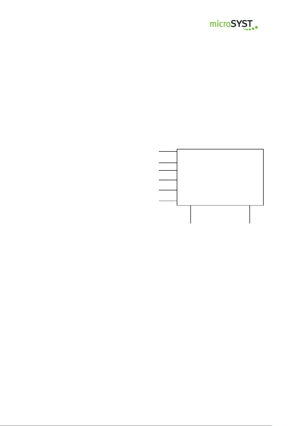
migan/migra IZ
Pulse input
Incremental input
Reset/Preset
Counting input / counting direction
Reset inputs for outputs (optional)
2 relay outputs
(optional)
BCD preselection inputs (optional)
Voltage outputs
(optional)
Large Format LED Display with Pulse Counter
2 System Overview
microSYST Systemelectronic GmbH, Am Gewerbepark 11, 92670 Windischeschenbach
+49 9681 91960-0, +49 9681 91960-10, info@microsyst.de, www.microsyst.de
Page 4
Page 5

migan/migra MPB IZ
Large Format LED Display with Pulse Counter
3 Technical Data
Display type: 7 segment LED (migan), LED dot matrix (migra)
Digits: 1 to 100
Decimal point: configurable position
View: single or double sided
Inputs: 2 pulse inputs,
Second pulse input can be configured as input with
counting direction,
inputs for phase-delayed signals pulses (input for
incremental encoder (TTL))
Reset/preset input,
4 inputs (migan controller),
Optional preset inputs BCD
Outputs: 4 outputs (migan controller)
Cut-off frequencies: can be configured with MKS software
10 Hz, 100 Hz, 1 kHz, 10 kHz, 100 kHz, >1 MHz –
max. 2 MHz
Input level: adjustable with MKS software
(pulse input) 5 V, 10 V, 12 V, 15 V, 24 V, 36 V, Pull-up to 5 V
Input level: adjustable with MKS software
(Reset/preset) 5 V, 10 V, 12 V, 15 V, 24 V, 36 V, Pull-up to 5 V
Input level: U
(incremental input) U
Display options: counting value,
frequency (counting pulses per time unit),
number of revolutions,
cycle duration,
speed (incremental input),
customer-specific
Dimensional display: upon request
Operation voltage: 230 V / 50 Hz, 110 V / 60 Hz or 24 VDC +/-20 %
Housing: industrial version, powder coated aluminium
Mounting: articulated arm, hanging with chain, angle brackets
Protection: IP54 or IP65
Operating temperature: 0 to +50 C (optional -20 to +50 °C)
Storage temperature: -25 to +70 C
0 VDC
low
5 VDC
high
microSYST Systemelectronic GmbH, Am Gewerbepark 11, 92670 Windischeschenbach
+49 9681 91960-0, +49 9681 91960-10, info@microsyst.de, www.microsyst.de
Page 5
Page 6

migan/migra MPB IZ
Large Format LED Display with Pulse Counter
3.1 Tips for the Start-up
When putting on the power supply, the following sequence has to be ob-
served:
o Connect the power supply cable to the display.
o Connect the power supply cable to the power supply.
When disconnecting the power supply, the following sequence has to be
observed:
o Disconnect the power supply cable from the power supply.
o Disconnect the power supply cable from the display.
microSYST Systemelectronic GmbH, Am Gewerbepark 11, 92670 Windischeschenbach
+49 9681 91960-0, +49 9681 91960-10, info@microsyst.de, www.microsyst.de
Page 6
Page 7

migan/migra MPB IZ
Large Format LED Display with Pulse Counter
3.2 Description of the Signals
Pulse input, UP / DOWN Switching
Status of the second pulse input specifies the counting direction of the
first pulse input. Status HIGH -> upwards, status LOW -> downwards
Incremental Input
Differential inputs (5 V level) for two phase-delayed signals. The upwards or
downwards counting happens according to the phase shift of the both signals.
IDx, phase a and phase B can be inverted with MKS software.
Reset / Preset
The reset/preset input can be configured with MKS software for edge
detection or status of input. The counter is always set to the preset val-
ue. The input acts as reset input, if preset value = 0. The preset value
can be set vial BCD preset values, MKS software, frame or script.
microSYST Systemelectronic GmbH, Am Gewerbepark 11, 92670 Windischeschenbach
+49 9681 91960-0, +49 9681 91960-10, info@microsyst.de, www.microsyst.de
Page 7
Page 8
migan/migra MPB IZ
U
high
= 5 - 36 VDC
U
low
= 0 VDC
f = 0 Hz to 2 MHz
Large Format LED Display with Pulse Counter
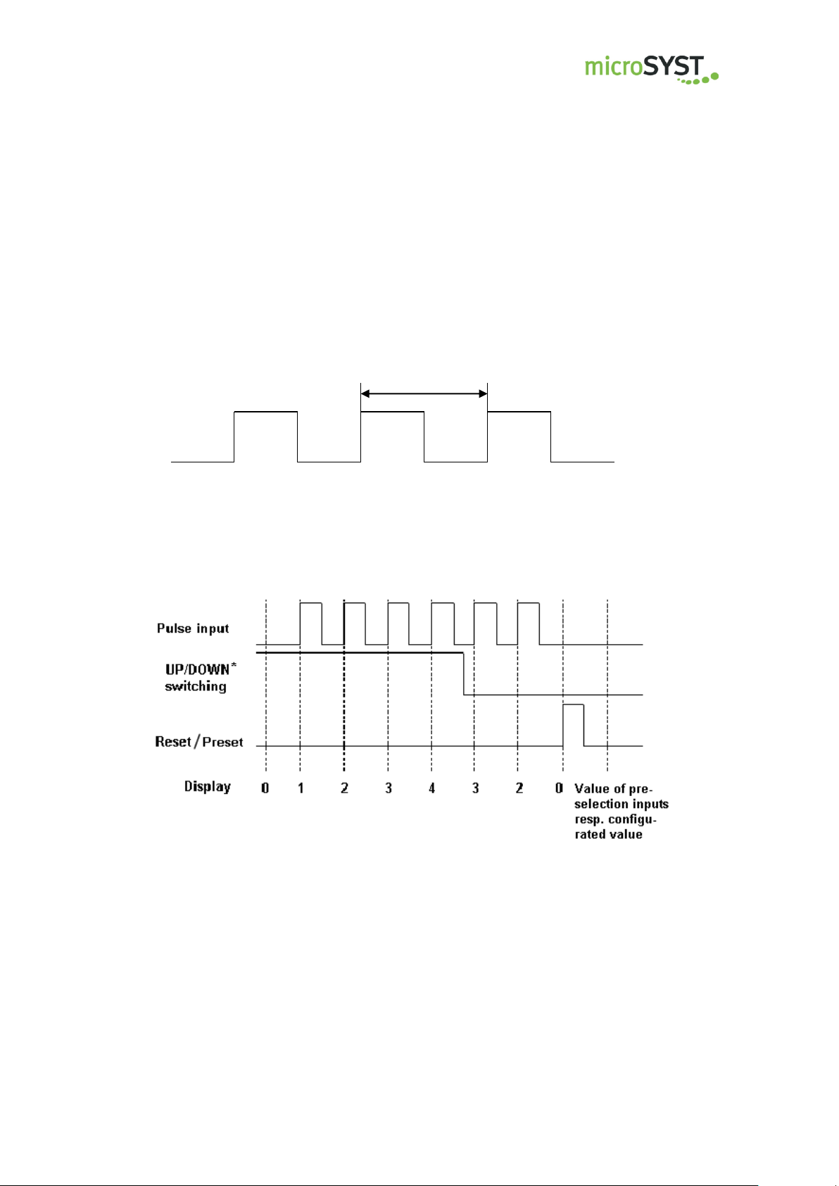
3.3 Pulse Diagrams
3.3.1 Pulse Input
Signal level and signal frequency:
Counting behaviour:
*: The direction switching could possibly be executed a few milliseconds
after changing the level.
microSYST Systemelectronic GmbH, Am Gewerbepark 11, 92670 Windischeschenbach
+49 9681 91960-0, +49 9681 91960-10, info@microsyst.de, www.microsyst.de
Page 8
Page 9

migan/migra MPB IZ
Pulse input A
Pulse input B
Display
0 1 2 3 4
f
= 0 Hz to 1 MHz
1
0
Large Format LED Display with Pulse Counter
3.3.2 Incremental Input
At the incremental inputp, the counting direction depends on the phase shift
of the two signals. The maximum frequency of a single input is 1 MHz.
If pulse channel A hurries ahead the channel B by 90 degrees (like in the
picture above), an UP-counting happens. If channel B hurries ahead the
channel A by 90 degrees, a DOWN-counting happens. This can be inverted
with MKS software.
microSYST Systemelectronic GmbH, Am Gewerbepark 11, 92670 Windischeschenbach
+49 9681 91960-0, +49 9681 91960-10, info@microsyst.de, www.microsyst.de
Page 9
Page 10
migan/migra MPB IZ
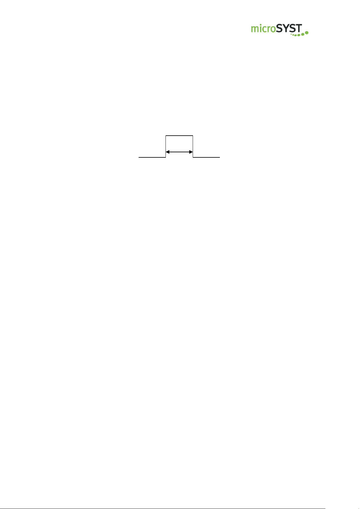
t
i
= pulse duration
U
high
= 5 - 36 VDC
U
low
= 0 VDC
Large Format LED Display with Pulse Counter
3.3.3 Control Inputs
Reset / Preset Input
The pulse duration ti is adjustable from 0 to 255 ms. Pulse duration > 10 if
value is 0.
microSYST Systemelectronic GmbH, Am Gewerbepark 11, 92670 Windischeschenbach
+49 9681 91960-0, +49 9681 91960-10, info@microsyst.de, www.microsyst.de
Page 10
Page 11
migan/migra MPB IZ
Large Format LED Display with Pulse Counter
3.4 Device Configuration migan
Itemnumber :_________________________
Character height:
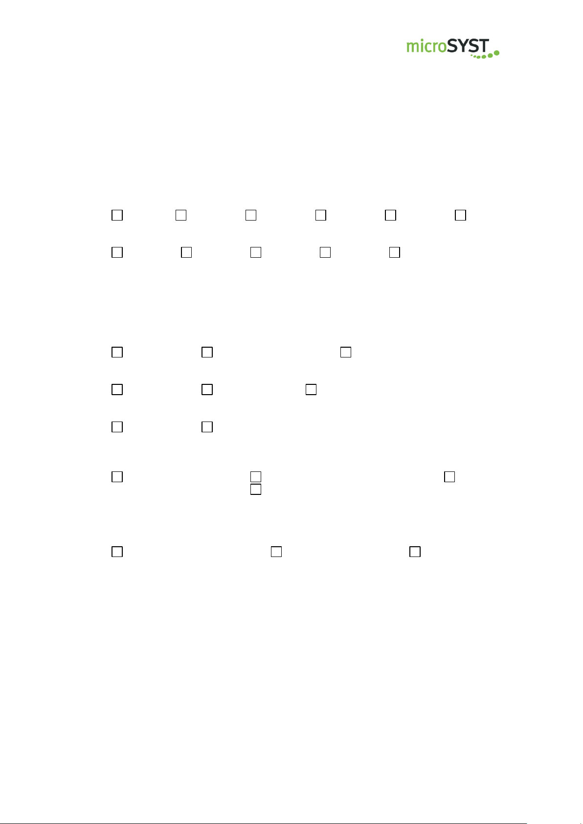
60 mm 100 mm 150 mm 200 mm 250 mm 300 mm
Display colour:
red green yellow white blue
Number of lines: ________ Number of digits per line: ________
Dimensional display:
_________________
View:
single sided double sided ____ sided
Operating voltage:
230 V / 50 Hz 110 V / 60 Hz 24 V DC
Protection:
IP54 IP65
Operating temperature:
with type for inside use: with type for outside use: special version:
0...+50 °C (standard) -20...+50 °C (standard) ___________ °C
-25...+50 °C (optional with heating)
Housing dimension: _________x_________x_________mm
Housing Material:
Aluminum profile Stainless steel Sheet metal
microSYST Systemelectronic GmbH, Am Gewerbepark 11, 92670 Windischeschenbach
+49 9681 91960-0, +49 9681 91960-10, info@microsyst.de, www.microsyst.de
Page 11
Page 12

migan/migra MPB IZ
Large Format LED Display with Pulse Counter
3.5 Device Configuration migra
Itemnumber :_________________________
Pixel resolution (horizontal x vertical): ________x________
Display colour:
red green yellow white blue
View:
single sided double sided ____ sided
Operating voltage:
230 V / 50 Hz 110 V / 60 Hz 24 VDC
Protection:
IP54 IP65
Operating temperature:
with type for inside use: with type for outside use: special version:
0...+50 °C (standard) -20...+50 °C (standard) ___________ °C
-25...+50 °C (optional with heating)
Housing dimension: _______x_______x_______mm
Housing Material:
Aluminum profile Stainless steel Sheet metal
microSYST Systemelectronic GmbH, Am Gewerbepark 11, 92670 Windischeschenbach
+49 9681 91960-0, +49 9681 91960-10, info@microsyst.de, www.microsyst.de
Page 12
Page 13

migan/migra MPB IZ
Pin
Assignment
1
GND
2
+24 VDC
3
PE
Pin
Assignment
1
L1 2 N
(PE)
PE
Large Format LED Display with Pulse Counter
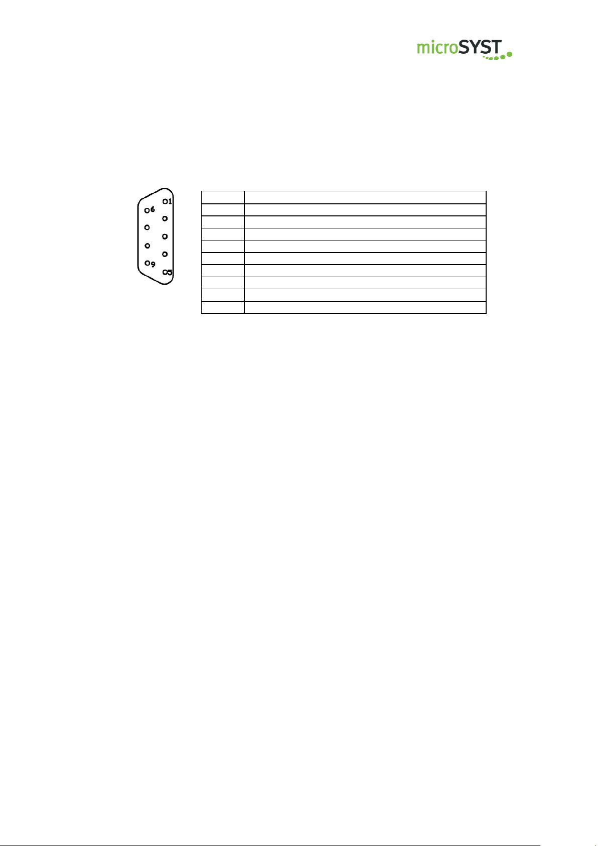
4 Connector Pin Assignments
The power supply happens with the 3-pin circular connector (+24 VDC).
Optionally it’s possible to supply with the 7-Pole mains plug (230 VAC).
Power Connector 24 VDC
Power Connector 230 VAC (optional)
microSYST Systemelectronic GmbH, Am Gewerbepark 11, 92670 Windischeschenbach
+49 9681 91960-0, +49 9681 91960-10, info@microsyst.de, www.microsyst.de
Page 13
Page 14

migan/migra MPB IZ
Pin
Assignment
1*
A+ (incremental input, 5 V)
2*
B+ (incremental input, 5 V)
3***
Output +15 VDC
4*
A- (incremental input, 5 V)
5**
Pulse input 1 (5 - 36 V)
resp. B- (incremental input, 5 V)
6
Pulse input 2 (5 – 36 V)
Resp. B- (incremental input, 5 V)
7
GND
8
n.c. 9 Reset input (+5 - 36 V = 1, 0 V = 0)
* = optional
** = at version with incremental inputs, this pin is used
for the signal B- !
*** = This pin is only optionally connected!
Depending on the display’s version, the voltage at this output
can also be +24 VDC!
Large Format LED Display with Pulse Counter
Pulse and Control Inputs (9-Pin Sub-D Plug Connector)
Input Impedances
Standard inputs: > 38 kΩ
Incremental inputs: > 5 kΩ
microSYST Systemelectronic GmbH, Am Gewerbepark 11, 92670 Windischeschenbach
+49 9681 91960-0, +49 9681 91960-10, info@microsyst.de, www.microsyst.de
Page 14
Page 15
migan/migra MPB IZ
Pin
Assignment
1**
Output +15 VDC
2
GND
3*
Relay 1, make resp. break contact
4*
Relay 1, common contact
5*
Relay 2, make resp. break contact
6*
Relay 2, common contact
7
Relay 1 reset input (+24 V = 1, 0 V = 0)
8
Relay 2 reset input (+24 V = 1, 0 V = 0)
9
n. c.
n. c. = not connected
* = potential-free outputs, depending on mounting variation: make or
break contact: maximum switching voltage/current 24 VDC / 1 A
** = This pin is only optionally connected!
Depending on the display’s version, the voltage at this output
can also be +24 VDC!
together with Pin 3, pulse inputs (previous page),
max. current 0,5 A
Large Format LED Display with Pulse Counter
Relay Outputs (9-Pin Sub-D Plug Connector, optionally mounted)
microSYST Systemelectronic GmbH, Am Gewerbepark 11, 92670 Windischeschenbach
+49 9681 91960-0, +49 9681 91960-10, info@microsyst.de, www.microsyst.de
Page 15
Page 16
migan/migra MPB IZ
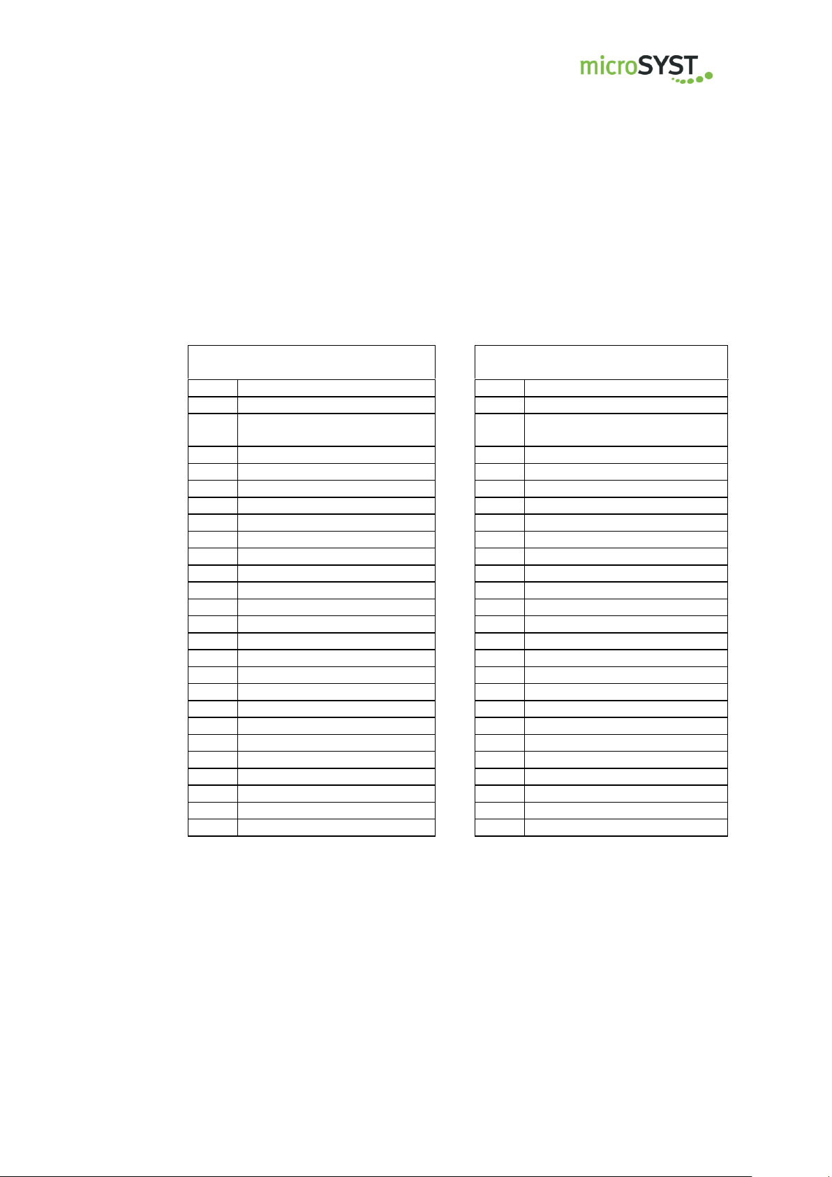
BCD parallel
BCD multiplex
Pin
Assignment
Pin
Assignment
1
GND
1
GND
2
Output for preselection inputs
(+15 or +24 VDC)
2 Output for preselection inputs
(+15 or +24 VDC)
3
Data 20/103
3
LE 105
4
Data 21/103
4 5
Data 22/103
5 6
Data 23/103
6
LE 104 7
7 8
Data 20/102
8 9
Data 21/102
9
LE 103
10
Data 22/102
10 11
Data 23/102
11 12
12
LE 102
13
Data 20/101
13 14
Data 21/101
14 15
Data 22/101
15
LE 101
16
Data 23/101
16 17
17 18
Data 20/100
18
LE 100
19
Data 21/100
19 20
Data 22/100
20 21
Data 23/100
21
Data 20
22
LE (latch enable)
22
Data 21
23
23
Data 22
24
24
Data 23
25
25
Large Format LED Display with Pulse Counter
Preselection Inputs (25-Pin Sub-D Plug Connector, optionally mounted)
Depending on device type, the preselection inputs are operated in mode
BCD parallel or BCD multiplex:
microSYST Systemelectronic GmbH, Am Gewerbepark 11, 92670 Windischeschenbach
+49 9681 91960-0, +49 9681 91960-10, info@microsyst.de, www.microsyst.de
The LE connections (latch enable) are LOW-active.
The ouput voltage of Pin 2 can be used for wiring the preselection inputs.
If the wiring shall happen with an external voltage, its GND must be connected
to Pin 1.
Page 16
Page 17
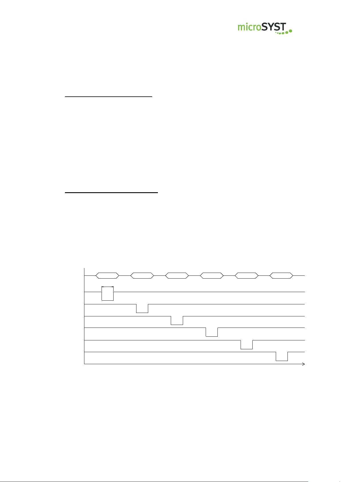
migan/migra MPB IZ
A...D
LE 100
2 ms
LE 101
LE 102
LE 103
LE 104
LE 105
100
101
102
103
104
105
t
Large Format LED Display with Pulse Counter
Procedure with BCD parallel:
Switch data signals to the display digits (HIGH-active).
Set preset input (HIGH-active).
The LE input must not be operated because it is automatically supplied with a LOW
signal if it’s not connected. In this case it is active.
Procedure with BCD multiplex:
Set an HIGH-signal to the display digits you want to use.
Set data signals for digit 100.
Activate LE 100 (= interrupt HIGH-signal or connect LOW-signal).
Repeat the last two steps for all display digits:
Set preset input (HIGH-active).
microSYST Systemelectronic GmbH, Am Gewerbepark 11, 92670 Windischeschenbach
+49 9681 91960-0, +49 9681 91960-10, info@microsyst.de, www.microsyst.de
Page 17
Page 18
migan/migra MPB IZ
Das bezeichnete Produkt stimmt mit
der folgenden Europäischen Richtlinie
überein:
We herewith confirm that the above mentioned product meets the requirements of
the following standard:
Die Übereinstimmung des bezeichneten Produktes mit den Vorschriften der angewandten Richtlinie(n) wird nachgewiesen durch die Einhaltung
folgender Normen / Vorschriften:
The conformity of the product described above with
the provisions of the applied Directive(s) is demonstrated by compliance with the following standards /
regulations:
Richtlinien / Directives
Europäische Norm / Standard
EMV Richtlinie
EMC Directive
2014/30/EU
EN61000-6-2:2005
EN61000-6-4:2007 +A1:2011
NiederspannungsRichtlinie
Low Voltage Directive
2014/35/EU
EN60950-1:2006 +A11:2009 +A1:2010 +A12:2011
+A2:2013
RoHS Richtlinie
RoHS Directive
2011/65/EU
EN50581:2012
Large Format LED Display with Pulse Counter
5 Appendix
5.1 Declaration of Conformity
EU-Konformitätserklärung
EU Declaration of Conformity
Produktbezeichnung: migan/migra
Product name:
Typenreihe: migan/migra IZ
Type code:
Hersteller: microSYST Systemelectronic GmbH
Manufacturer: Am Gewerbepark 11
92670 Windischeschenbach
Windischeschenbach, 16.11.2017
Manuel Raß
Geschäftsführer / General Manager
microSYST Systemelectronic GmbH, Am Gewerbepark 11, 92670 Windischeschenbach
+49 9681 91960-0, +49 9681 91960-10, info@microsyst.de, www.microsyst.de
Page 18
Page 19

migan/migra MPB IZ
Large Format LED Display with Pulse Counter
5.2 Maintenance and Care
Please observe the following instructions:
Make sure that the housing can be opened for adjustment and
maintenance even after the display has been installed. Allow for adequate clearance at the back, front and top of the display unit in order to allow for sufficient ventilation (if vent slots are included).
Display quality is impaired by direct illumination with bright light
sources and/or direct sunlight.
The display must be switched off before cleaning.
Protect the display from excessive humidity, extreme vibration, di-
rect sunlight and extreme temperatures. Non-observance may lead
to malfunctioning or destruction of the device. Under certain circumstances electrical shock, fire and explosion may occur as well.
Information concerning allowable ambient conditions, including recommended temperature ranges, can be found in the chapter entitled “Technical Data”.
The display may not be placed into service if the device and/or the
power cable are known to be damaged.
Do not attempt to repair the device yourself. The guarantee is ren-
dered null and void if the device is tampered with by unauthorised
persons.
Observe all notes and instructions included in this user’s manual.
microSYST Systemelectronic GmbH, Am Gewerbepark 11, 92670 Windischeschenbach
+49 9681 91960-0, +49 9681 91960-10, info@microsyst.de, www.microsyst.de
Page 19
Page 20

migan/migra MPB IZ
Large Format LED Display with Pulse Counter
5.3 Warranty / Liability
For the product, liability is assumed for defects, which existed at the de-
livery date according to our General Terms and Conditions.
Technically changes as well as errors are excepted. A claim for delivery
of a new product does not exist. The buyer has to check the received
product immediately and indicate evident defects at the latest 24 hours
after detection. Non-observance of notification requirements is equated
with acceptance of the defect. Not immediately visible defects have to
be indicated immediately after their perception too.
Generally, defects and their symptoms must be described as accurately
as possible in order to allow for reproducibility and elimination. The buy-
er must provide for access to the relevant device and all required and/or
useful information at no charge and must make all of the required data
and machine time available free of charge.
The guarantee does not cover defects, which result from non-
observance of the prescribed conditions of use, or from improper han-
dling.
If the device has been placed at the disposal of the buyer for test pur-
poses and has been purchased subsequent to such testing, both parties
agree that the product is to be considered “used” and that it has been
purchased “as is”. No guarantee claims may be made in such cases.
The General Terms and Conditions of microSYST Systemelectronic
GmbH in current version apply as well.
microSYST Systemelectronic GmbH, Am Gewerbepark 11, 92670 Windischeschenbach
+49 9681 91960-0, +49 9681 91960-10, info@microsyst.de, www.microsyst.de
Page 20
Page 21
migan/migra MPB IZ
Version
Date
Remark, Description
1.00
1.01
1.10
1.20
1.30
1.40
1.50
1.60
1.70
1.80
1.90
2.00
2.10
2.20
3.00
3.10
03.11.03
08.12.03
28.10.04
22.11.04
13.03.06
15.12.00
02.09.08
24.09.09
16.08.10
31.01.11
15.01.13
21.03.13
17.10.13
27.04.16
16.11.16
13.11.17
Gold S.: Document created
Gold S.: Default voltage for voltage outputs changed
Kreuzer: Housing dimensions changed
Kreuzer: Complete revised
Kreuzer: Second counting input instead of counting direction
is possible
Kreuzer: Optionally 5 Hz impulse input
Kreuzer: Max. output current limited to 0.5 A
Kreuzer: Impedances of the inputs
Technical Data updated
migan AW added
Description for preselection inputs changed
Company address, declaration of conformity, warranty changed
Logo
Declaration of conformity
migan2 migan MPB; migra migra MPB
Change of address and title MPB
Large Format LED Display with Pulse Counter
5.4 Versions Overview
Certified per DIN EN ISO 9001.
microSYST Systemelectronic GmbH, Am Gewerbepark 11, 92670 Windischeschenbach
+49 9681 91960-0, +49 9681 91960-10, info@microsyst.de, www.microsyst.de
Page 21
 Loading...