

Page 1
microSYST Systemelectronic GmbH, Am Gewerbepark 11, 92670 Windischeschenbach
+49 9681 91960-0, +49 9681 91960-10, info@microsyst.de, www.microsyst.de
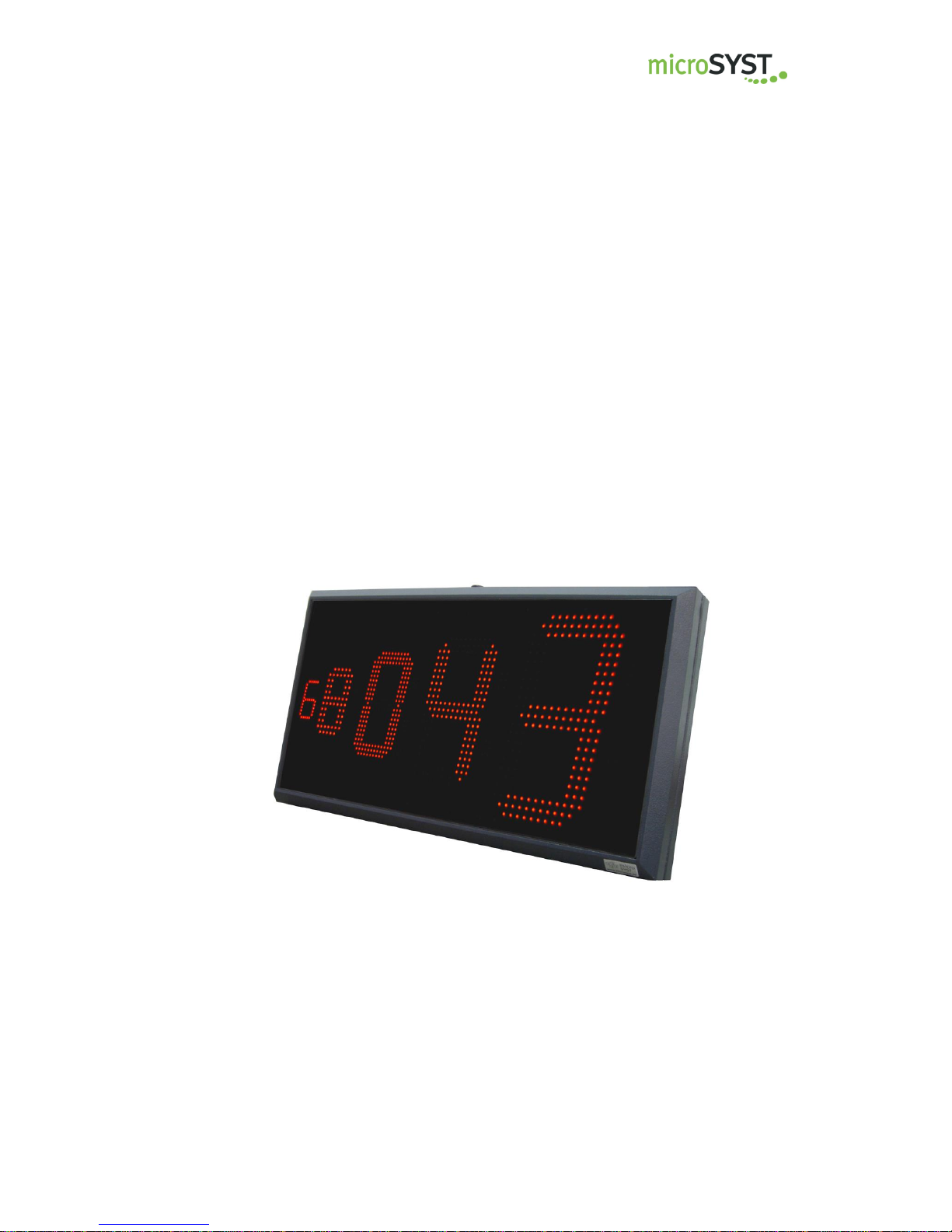
migan Ethernet IP
Large Format Numeric LED Display with Ethernet IP Interface
User manual
Page 2

migan Ethernet IP
Large Format Numeric LED Display with Ethernet IP Interface
Page 2
microSYST Systemelectronic GmbH, Am Gewerbepark 11, 92670 Windischeschenbach
+49 9681 91960-0, +49 9681 91960-10, info@microsyst.de, www.microsyst.de
Index
1 GENERAL 3
2 TECHNICAL INFORMATION 3
2.1 Device Configuration 4
2.2 Connector Pin Assignments 5
2.3 Device Start 6
2.4 Ethernet IP Configuration 7
3 CONTROL DATA 8
3.1 Control Frame (Display Output) 8
3.2 Response Frame (from Display) 11
4 APPENDIX 12
4.1 Displayable Characters 12
4.2 Ethernet IP Diagnostics 13
4.3 Factory Settings 15
4.4 General Notes 16
4.5 Declaration of Conformity 17
4.6 Warranty / Liability 18
4.7 Versions Overview 19
Page 3

migan Ethernet IP
Large Format Numeric LED Display with Ethernet IP Interface
Page 3
microSYST Systemelectronic GmbH, Am Gewerbepark 11, 92670 Windischeschenbach
+49 9681 91960-0, +49 9681 91960-10, info@microsyst.de, www.microsyst.de
1 General
This 7 segment displays are designed for professional use. Depending on the
type of device, they are suitable for indoor or outdoor use.
The modular design allows for cost-effective models of various interfaces with different character heights and numbers of digits.
2 Technical Information
Display type:
7 segment LED
Character heights:
Indoor use: 60 / 100 / 150 / 200 / 250 mm
Outdoor use: 100 / 200 / 300 mm
Number of digits:
1...40
Number of lines:
Standard 1 line, multiple lines on request
Display colour:
Standard red, other colours on request
Operating voltage:
230 VAC / 50 Hz, 110 VAC / 60 Hz or 24 VDC ±20%
Interface:
Ethernet/IP
Connection
RJ45, 10/100 MBit/s,
configuration via RS232 interface
View:
Single sided to four sided
Displayable characters:
see corresponding chapter
Labelling:
on request
Housing:
Industrial version, powder coated aluminum
Housing colour:
RAL 7016 (anthracite)
Mounting:
Articulated arm, angle bracket, hanging on chain or
mounting frame
Protection:
see chapter “Device Configuration“
Operating temp.:
see chapter “Device Configuration“
Storage temp.:
-25 ... +70 °C
Page 4
migan Ethernet IP
Large Format Numeric LED Display with Ethernet IP Interface
Page 4
microSYST Systemelectronic GmbH, Am Gewerbepark 11, 92670 Windischeschenbach
+49 9681 91960-0, +49 9681 91960-10, info@microsyst.de, www.microsyst.de
2.1 Device Configuration
Type:
for inside use for outside use
Character height:
60 mm 100 mm 150 mm 200 mm 250 mm 300 mm
Number of lines: ________ Number of digits per line: ________
Display colour:
red green yellow white blue
View:
single sided double sided ____ sided
Operating voltage:
230 VAC / 50 Hz 110 VAC / 60 Hz 24 VDC
Protection:
IP40 IP54 IP65 IP _____
Operating temperature:
with type for inside use: with type for outside use: special version:
0...+50 °C (standard) -20...+50 °C (standard)
-25...+50 °C (optional with heating) ____________ °C
Housing dimensions: _________x_________x_________mm
Housing Material:
Aluminum profile Stainless steel Sheet metal
Page 5
migan Ethernet IP
Large Format Numeric LED Display with Ethernet IP Interface
Page 5
microSYST Systemelectronic GmbH, Am Gewerbepark 11, 92670 Windischeschenbach
+49 9681 91960-0, +49 9681 91960-10, info@microsyst.de, www.microsyst.de
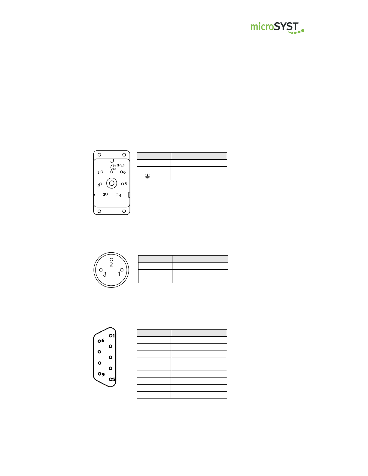
2.2 Connector Pin Assignments
Please see inside labelling of the mating plugs for pin assignment.
Power Connector 230 VAC
Power Connector 24 VDC (optional)
Connector RS232-HMS
Pin
Assignment
1
L1 2 N
(PE)
PE
Pin
Assignment
1
GND
2
+24 VDC
3
PE
Pin
Assignment
1 2
RxD
3
TxD 4 5 GND 6 7 8 9
Page 6
migan Ethernet IP
Large Format Numeric LED Display with Ethernet IP Interface
Page 6
microSYST Systemelectronic GmbH, Am Gewerbepark 11, 92670 Windischeschenbach
+49 9681 91960-0, +49 9681 91960-10, info@microsyst.de, www.microsyst.de
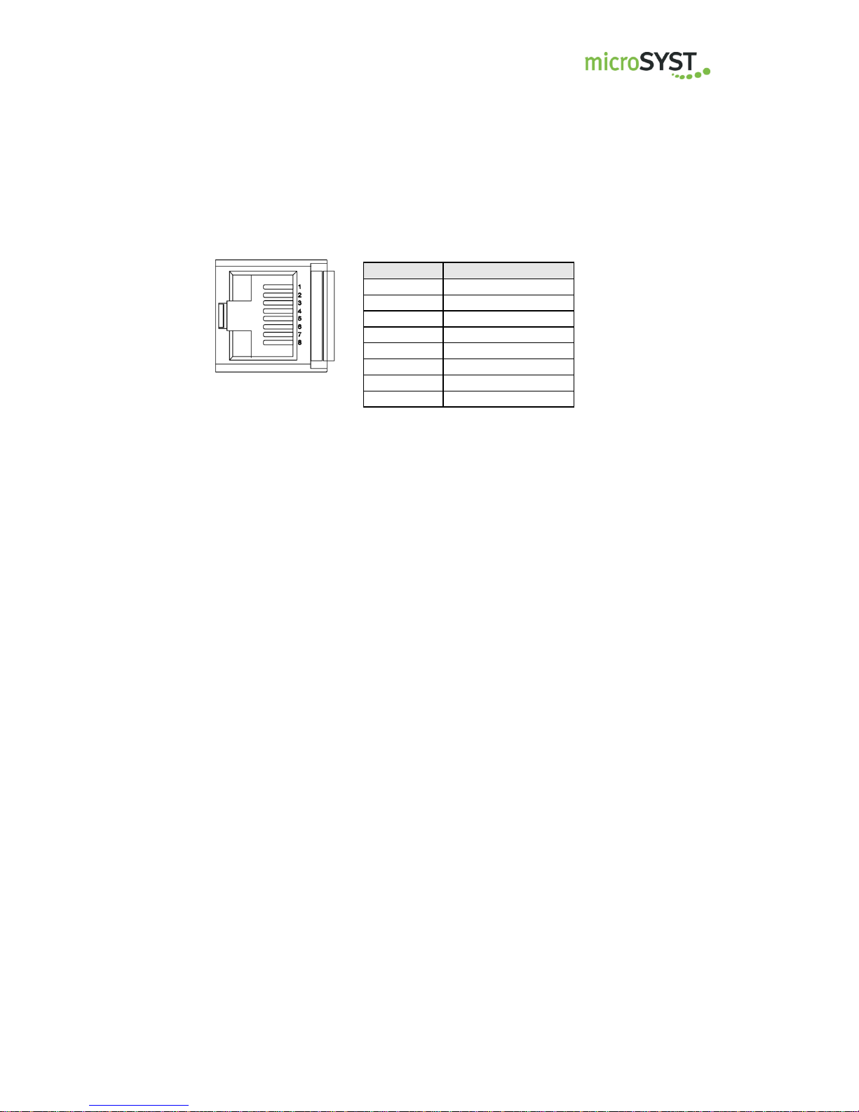
Ethernet Socket
2.3 Device Start
Following things are displayed after power up:
Segment test
<first 2 digits of the baud rate > <parity> <data bits>
A<display address>
Shown parameters refer to the internal interface and are not significant
for Ethernet/IP operation.
Pin
Assignment
1
Tx +
2
Tx -
3
Rx + 4 5 6 Rx - 7 8
Page 7

migan Ethernet IP
Large Format Numeric LED Display with Ethernet IP Interface
Page 7
microSYST Systemelectronic GmbH, Am Gewerbepark 11, 92670 Windischeschenbach
+49 9681 91960-0, +49 9681 91960-10, info@microsyst.de, www.microsyst.de
2.4 Ethernet IP Configuration
The software “Anybus Configuration Manager” of the company HMS serves for the
configuration of the interface. You can find this tool at the web page of the interface manufacturer www.anybus.com in the area SUPPORT -> Anybus Communicator -> Ethernet Serial Gateway.
Connect the display with a RS232 null modem cable (pins 2<->3, 3<->2,
5<->5) to a PC / Laptop.
Start the software.
Close the window “Konfiguration auswählen” with the button “Cancel”.
Press button “Verbinden” and after that button “Upload”.
Change only the marked fields according to your requirements
Click button “Download” to transmit the configuration to the interface.
Now the interface configuration is completed.
You can find the original configuration at our home page www.microsyst.de in the
area “Downloads & Support” -> “migan” -> “Ethernet IP” -> “Configuration File for
HMS Interface”.
Upload
Verbinden
Download
Page 8

migan Ethernet IP
Large Format Numeric LED Display with Ethernet IP Interface
Page 8
microSYST Systemelectronic GmbH, Am Gewerbepark 11, 92670 Windischeschenbach
+49 9681 91960-0, +49 9681 91960-10, info@microsyst.de, www.microsyst.de
3 Control Data
3.1 Control Frame (Display Output)
The transmission bytes are written as of the address 0x202 into the display interface.
The corresponding Ethernet IP output addresses result from chapter “Memory Layout”
of the “Anybus Communicator EtherNet/IP / Modbus-TCP User Manual“
(www.anybus.com). Please pay attention to sufficient size of the output area.
TB
LEN1
ADR
LEN2
O1
►
Toggle
Byte*
Number of
following bytes
(from ADR to CHK)
Device
address
Number of
following bytes
(from O1 to CHK)
Options
00H…FFH 08H ... n
01H 06H ... n
Bit 7: report software version**
Bit 6: 0 = Statically display the
last received data
(standard)
1 = Display “----“, if no new
data are received within 5 s.
Bits 5...4: Brightness
00 = 100%
01 = 80%
10 = 60%
11 = 40%
Bit 3 = Digital output 4
Bit 2 = Digital output 3
Bit 1 = Digital output 2
Bit 0 = Digital output 1
Output will be set,
if corresponding bit = 1
** only at communication with response frame
*Toggle byte:
The toggle byte must be increased by 1, if the frame shall be processed
Page 9

migan Ethernet IP
Large Format Numeric LED Display with Ethernet IP Interface
Page 9
microSYST Systemelectronic GmbH, Am Gewerbepark 11, 92670 Windischeschenbach
+49 9681 91960-0, +49 9681 91960-10, info@microsyst.de, www.microsyst.de
O2
►
Output format
Bits 7...4: Physical number of digits (bit coded)
0001...1111 = 1...15 digits
0000 = ASCII representation with up to 40 digits
Bit 3: Mode
0 = LSB first: data byte D1 = lo
1 = MSB first
Bits 2...0: Data type* max. number of digits
000 = unsigned CHAR (0...255) 3
001 = unsigned INT (0...65535) 5
010 = unsigned LONG (0...4294967296) 10
011 = signed CHAR (-128...127) 4
100 = signed INT (-32768...32767) 6
101 = signed LONG (-2147483648... 2147483647) 11
110 = ASCII representation 40
111 = reserved
* at value representation: right-aligned display
at ASCII representation: left-aligned display
O3
O4
►
Decimal points / colons
Decimal points / colons, blinking
Bit 7 = Point for digit 1
Bit 6 = Point for digit 2
Bit 5 = Point for digit 3
Bit 4 = Point for digit 4
Bit 3 = Point for digit 5
Bit 2 = Point for digit 6
Bit 1 = Point for digit 7
Bit 0 = Point for digit 8
Bit 7 = Point for digit 9
Bit 6 = Point for digit 10
Bit 5 = Point for digit 11
Bit 4 = Point for digit 12
Bit 3 = Point for digit 13
Bit 2 = Point for digit 14
Bit 1 = Point for digit 15
Bit 0 = Display blinks
A point is set, if corresponding bit = 1
Either a decimal point or a colon can be displays (depending on ordering option).
Page 10

migan Ethernet IP
Large Format Numeric LED Display with Ethernet IP Interface
Page 10
microSYST Systemelectronic GmbH, Am Gewerbepark 11, 92670 Windischeschenbach
+49 9681 91960-0, +49 9681 91960-10, info@microsyst.de, www.microsyst.de
D1…Dn
CHK
Data bytes (value- or ASCII representation)
Checksum
Value representation:
CHAR value: 1 byte
INT value: 2 bytes
LONG value: 4 bytes
ASCII representation (max. 80 bytes):
1 byte per character, max. 40 digits,
Bit 7 = 1: digit blinks
The decimal point has character code 2CH or
2EH and is always set at the previous digit.
depending on S4-DIP5:
standard: 55H (fixed value)
or
LOW byte of the sum of
bytes ADR...Dn
Controlling devices with multiple display areas (e.g. 2 lines):
The partition from O2…Dn is used repeatedly according to the number of
display areas (see example 3).
Please attend to the maximum total frame length of 152 bytes.
Example 1:
Display with 4 digits, unsigned INT (LSB first), brightness = 60%, display value = 1.23
TB 09 01 07 20 41 40 00 7B 00 55
Example 2:
Display with 4 digits, ASCII representation, brightness = 60%, display value = 12.34
TB 0C 01 0A 20 46 00 00 31 32 2E 33 34 55
Example 3:
Display with 2 lines and 4 digits per line, unsigned INT (LSB first),
display value for line 1 = 1.23,
display value for line 2 = 5.67
TB 0E 01 0C 00 41 40 00 7B 00 41 40 00 37 02 55
\______________/\______________/
Line 1 Line 2
(O2...D2) (O2...D2)
Page 11

migan Ethernet IP
Large Format Numeric LED Display with Ethernet IP Interface
Page 11
microSYST Systemelectronic GmbH, Am Gewerbepark 11, 92670 Windischeschenbach
+49 9681 91960-0, +49 9681 91960-10, info@microsyst.de, www.microsyst.de
3.2 Response Frame (from Display)
The display writes the response frame as of the address 0x160.
The corresponding Ethernet IP input addresses result from chapter “Memory Layout”
of the “Anybus Communicator EtherNet/IP / Modbus-TCP User Manual“
(www.anybus.com). Please pay attention to sufficient size of the input area.
Digital inputs are optionally available (depending on display type).
TB
LEN1
ADR
LEN2
I1
CHK
Toggle
byte*
Length
Device
address
Length
Digital Inputs
Checksum
00H…FFH
04H 01H
02H
Bit 7 = Event digital input 4
Bit 6 = Event digital input 3
Bit 5 = Event digital input 2
Bit 4 = Event digital input 1
Bit 3 = Status digital input 4
Bit 2 = Status digital input 3
Bit 1 = Status digital input 2
Bit 0 = Status digital input 1
depending on S4-DIP5:
standard: 55H (fixed value)
or
LOW byte of the sum of
the bytes ADR + LEN + I1
*Toggle byte:
The toggle byte is increased by 1, if there comes a response from the display.
Event of a digital input = 1, if it has been set at least once since the last query.
The event is deleted after every query.
Status of a digital input = 1, if it’s set at the moment.
Example
Response frame, if digital input 3 is set
TB 04 01 02 04 55
Page 12

migan Ethernet IP
Large Format Numeric LED Display with Ethernet IP Interface
Page 12
microSYST Systemelectronic GmbH, Am Gewerbepark 11, 92670 Windischeschenbach
+49 9681 91960-0, +49 9681 91960-10, info@microsyst.de, www.microsyst.de
4 Appendix
4.1 Displayable Characters
The data bytes are ASCII coded:
Lower
Higher
0 1 2 3 4 5 6
7
0
“Blank”
1
2
3
4
5
6
7
8
9
A
B
C
. / : *
D
E
. / : *
F
*Either decimal point or colon can be displays. This depends on ordering option.
Page 13

migan Ethernet IP
Large Format Numeric LED Display with Ethernet IP Interface
Page 13
microSYST Systemelectronic GmbH, Am Gewerbepark 11, 92670 Windischeschenbach
+49 9681 91960-0, +49 9681 91960-10, info@microsyst.de, www.microsyst.de
4.2 Ethernet IP Diagnostics
Please open the housing for diagnostics.
LED 1 - Module Status
State
Description
steady off
no supply power
steady green
device operational
flashing green
No Ethernet IP configuration
flashing red
recoverable fault
steady red
internal error
flashing green/red
self-test
LED 2 - Network Status
State
Description
steady off
no power or no IP address
steady green
Ethernet IP connection
flashing green
no Ethernet IP connection
flashing red
connection timeout
steady red
duplicate IP address
flashing green/red
self-test
LED 3 - Link
State
Description
steady green
module has a link
steady off
module does not sense a link
LEDs
DIP Switch (inside the housing)
Page 14

migan Ethernet IP
Large Format Numeric LED Display with Ethernet IP Interface
Page 14
microSYST Systemelectronic GmbH, Am Gewerbepark 11, 92670 Windischeschenbach
+49 9681 91960-0, +49 9681 91960-10, info@microsyst.de, www.microsyst.de
LED 4 - Activity
State
Description
flashing green
frame is received or transmitted
LED 5 - Subnet Status (RS485)
State
Description
steady off
power off
flashing green
initializing and not running
steady green
running
steady red
stopped, error or timeout
LED 6 - Device Status
State
Description
steady off
power off
flashing red/green
invalid or missing configuration
steady green
initializing
flashing green
normal operation
flashing red
error code
DIP Switch (inside the housing of the module)
All DIP switches must be switched off.
Page 15

migan Ethernet IP
Large Format Numeric LED Display with Ethernet IP Interface
Page 15
microSYST Systemelectronic GmbH, Am Gewerbepark 11, 92670 Windischeschenbach
+49 9681 91960-0, +49 9681 91960-10, info@microsyst.de, www.microsyst.de
4.3 Factory Settings
Please do not change the settings.
S4-DIP
OFF
ON
1
Baud rates 1200...9600
Baud rates 19200...115200
2
Data format: 7 bits
Data format: 8 bits
3
without response frame
with response frame
4
Protocol: Classic
Protokoll: Universal
DIP2 is ignored (8 bits, fixed)
5
fixed value (55H) instead of checksum
(only with protocol “Universal“)
use checksum
(only with protocol “Universal“)
6
Brightness control for inside displays
Brightness control for outside displays
7
Temperature/brightness sensor: Master
Temperature/brightness sensor: Slave
8
Standard
Evaluation of migra frames
(AD, IZ, BCD)
* Marked positions are set per default.
Factory settings (remaining switches)
S2 = „0“, S1 = „1“, S3 = „D“, S5-DIP1 = ON, S5-DIP2 = ON
LED
Green LED blinks with 2 Hz, if processor is running.
Page 16

migan Ethernet IP
Large Format Numeric LED Display with Ethernet IP Interface
Page 16
microSYST Systemelectronic GmbH, Am Gewerbepark 11, 92670 Windischeschenbach
+49 9681 91960-0, +49 9681 91960-10, info@microsyst.de, www.microsyst.de
4.4 General Notes
Please observe the following instructions:
When installing the device, always make sure that the installed
housing can be opened for adjustment or maintenance work. When
attaching the device, leave an appropriate space on the back / front
/ top to ensure adequate ventilation (if available).
Direct exposure to light sources or direct sun rays reduces the
reading quality.
Turn the device off for cleaning.
Protect the device from excessive moisture, strong vibrations, direct
sun exposure and extreme temperatures. If this is not observed, it
can cause function problems or device destruction. In addition,
there is the danger of electric shock, fire or explosion. Please refer
to "Technical Information" chapter for detailed information regarding
proper ambient conditions, especially recommended temperature
ranges.
The device may not be used if there is any damage on the device
and / or power line.
Do not attempt to repair the device yourself. Any interference by
unauthorized personnel will void the warranty.
Page 17

migan Ethernet IP
Large Format Numeric LED Display with Ethernet IP Interface
Page 17
microSYST Systemelectronic GmbH, Am Gewerbepark 11, 92670 Windischeschenbach
+49 9681 91960-0, +49 9681 91960-10, info@microsyst.de, www.microsyst.de
4.5 Declaration of Conformity
EU-Konformitätserklärung
EU Declaration of Conformity
Produktbezeichnung: migan
Product name:
Typenreihe: migan Ethernet IP
Type code:
Hersteller: microSYST Systemelectronic GmbH
Manufacturer: Am Gewerbepark 11
92670 Windischeschenbach
Das bezeichnete Produkt stimmt mit
der folgenden Europäischen Richtlinie
überein:
We herewith confirm that the above mentioned product meets the requirements of
the following standard:
Die Übereinstimmung des bezeichneten Produktes mit den Vorschriften der angewandten Richtlinie(n) wird nachgewiesen durch die Einhaltung
folgender Normen / Vorschriften:
The conformity of the product described above with
the provisions of the applied Directive(s) is demonstrated by compliance with the following standards /
regulations:
Richtlinien / Directives
Europäische Norm / Standard
EMV Richtlinie
EMC Directive
2014/30/EU
EN61000-6-2:2005
EN61000-6-4:2007 +A1:2011
NiederspannungsRichtlinie
Low Voltage Directive
2014/35/EU
EN60950-1:2006 +A11:2009 +A1:2010 +A12:2011
+A2:2013
RoHS Richtlinie
RoHS Directive
2011/65/EU
EN50581:2012
Windischeschenbach, 20.11.2017
Manuel Raß
Geschäftsführer / General Manager
Page 18

migan Ethernet IP
Large Format Numeric LED Display with Ethernet IP Interface
Page 18
microSYST Systemelectronic GmbH, Am Gewerbepark 11, 92670 Windischeschenbach
+49 9681 91960-0, +49 9681 91960-10, info@microsyst.de, www.microsyst.de
4.6 Warranty / Liability
For the product, liability is assumed for defects, which existed at the delivery date according to our General Terms and Conditions.
Technically changes as well as errors are accepted. A claim for delivery
of a new product does not exist. The buyer has to check the received
product immediately and indicate evident defects at the latest 24 hours
after detection. Non-observance of notification requirements is equated
with acceptance of the defect. Not immediately visible defects have to
be indicated immediately after their perception too.
Generally, defects and their symptoms must be described as accurately
as possible in order to allow for reproducibility and elimination. The buyer must provide for access to the relevant device and all required and/or
useful information at no charge and must make all of the required data
and machine time available free of charge.
The guarantee does not cover defects, which result from nonobservance of the prescribed conditions of use, or from improper handling.
If the device has been placed at the disposal of the buyer for test purposes and has been purchased subsequent to such testing, both parties
agree that the product is to be considered “used” and that it has been
purchased “as is”. No guarantee claims may be made in such cases.
The General Terms and Conditions of microSYST Systemelectronic
GmbH in current version apply as well.
Page 19

migan Ethernet IP
Large Format Numeric LED Display with Ethernet IP Interface
Page 19
microSYST Systemelectronic GmbH, Am Gewerbepark 11, 92670 Windischeschenbach
+49 9681 91960-0, +49 9681 91960-10, info@microsyst.de, www.microsyst.de
4.7 Versions Overview
Version
Date
Remarks, Description
1.00
1.10
18.07.16
20.11.17
Document created
Change of address
Certified per DIN EN ISO 9001.
 Loading...