

Micro Star Computer MS- 9130 User Manual
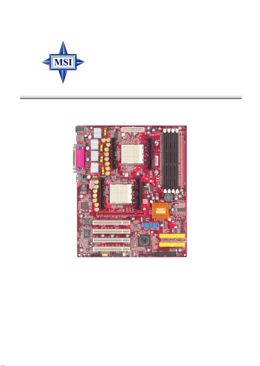
K8T Master2-FAR Series
MS-9130 (v1.X) Mainboard
Version 1.0
G52-S9130X1
i
Manual Rev: 1.0
Release Date: July 2003
FCC-A Radio Frequency Interference Statement
This equipment has been tested and found to comply with the limits for a class
A digital device, pursuant to part 15 of the FCC rules. These limits are designed
to provide reasonable protection against harmful interference when the equipment is operated in a commercial environment. This equipment generates, uses
and can radiate radio frequency energy and, if not installed and used in accordance with the instruction manual, may cause harmful interference to radio
communications. Operation of this equipment in a residential area is likely to
cause harmful interference, in which case the user will be required to correct
the interference at his own expense.
Notice 1
The changes or modifications not expressly approved by the party responsible for compliance could void the user’s authority to operate the equipment.
Notice 2
Shielded interface cables and A.C. power cord, if any, must be used in order to
comply with the emission limits.
VOIR LA NOTICE D’INSTALLATION AVANT DE RACCORDER AU
RESEAU.
Micro-Star International MS-9130
T ested to comply
with FCC Standard
For Home or Office Use
ii

Copyright Notice
The material in this document is the intellectual property of MICRO-STAR
INTERNATIONAL. We take every care in the preparation of this document,
but no guarantee is given as to the correctness of its contents. Our products
are under continual improvement and we reserve the right to make changes
without notice.
Trademarks
All trademarks are the properties of their respective owners.
AMD, Athlon™, Athlon™ XP, Thoroughbred™, and Duron™ are registered
trademarks of AMD Corporation.
Intel® and Pentium® are registered trademarks of Intel Corporation.
PS/2 and OS®/2 are registered trademarks of International Business Machines
Corporation.
Microsoft is a registered trademark of Microsoft Corporation. Windows® 98/
2000/NT/XP are registered trademarks of Microsoft Corporation.
NVIDIA, the NVIDIA logo, DualNet, and nForce are registered trademarks or
trademarks of NVIDIA Corporation in the United States and/or other countries.
Netware® is a registered trademark of Novell, Inc.
Award® is a registered trademark of Phoenix T echnologies Ltd.
AMI® is a registered trademark of American Megatrends Inc.
Kensington and MicroSaver are registered trademarks of the Kensington T echnology Group.
PCMCIA and CardBus are registered trademarks of the Personal Computer
Memory Card International Association.
Revision History
Revision Revision History Date
V1.0 First release July 2003
iii

Safety Instructions
1. Always read the safety instructions carefully.
2. Keep this User’s Manual for future reference.
3. Keep this equipment away from humidity.
4. Lay this equipment on a reliable flat surface before setting it up.
5. The openings on the enclosure are for air convection hence protects the
equipment from overheating. Do not cover the openings.
6. Make sure the voltage of the power source and adjust properly 110/220V
before connecting the equipment to the power inlet.
7. Place the power cord such a way that people can not step on it. Do not
place anything over the power cord.
8. Always Unplug the Power Cord before inserting any add-on card or module.
9. All cautions and warnings on the equipment should be noted.
10 . Never pour any liquid into the opening that could damage or cause electrical
shock.
11. If any of the following situations arises, get the equipment checked by a
service personnel:
z The power cord or plug is damaged.
z Liquid has penetrated into the equipment.
z The equipment has been exposed to moisture.
z The equipment has not work well or you can not get it work according
to User’s Manual.
z The equipment has dropped and damaged.
z The equipment has obvious sign of breakage.
12. Do not leave this equipment in an environment unconditioned, storage
temperature above 600 C (1400F), it may damage the equipment.
CAUTION: Danger of explosion if battery is incorrectly replaced.
Replace only with the same or equivalent type recommended by the
manufacturer.
警告使用者:
這是甲類的資訊產品,在居住的環境中使用時,可能會造成無線電干
擾,在這種情況下,使用者會被要求採取某些適當的對策。
iv

CONTENTS
FCC-A Radio Frequency Interference Statement ..........................................iii
Copyright Notice ..........................................................................................iii
Revision History ........................................................................................... iii
Safety Instructions ....................................................................................... v
Chapter 1. Getting Started ........................................................................ 1-1
Mainboard Specifications .................................................................... 1-2
Mainboard Layout ...............................................................................1-4
MSI Special Features ...........................................................................1-5
Core Center.................................................................................... 1-5
Chapter 2. Hardware Setup ....................................................................... 2-1
Quick Components Guide ....................................................................2-2
Central Processing Unit: CPU ..............................................................2-3
CPU Installation Procedures for Socket 940 .................................. 2-4
Installing the CPU heatsink/cooler ................................................2-5
Memory................................................................................................2-6
Installing DDR Modules ...............................................................2-6
Memory Population Rules.............................................................2-7
Power Supply ....................................................................................... 2-8
SSI 12V Power Connector: JPWR2 ................................................2-8
SSI 24-Pin Power Connector: JPR1 ................................................2-8
ATX 20-Pin Power Connector: ATX1 ............................................2- 9
SSI 8-Pin Power Connector: JPWR1 ............................................ 2-10
A TX 12V Power Connector: JPW1 .............................................. 2-10
Back Panel .......................................................................................... 2-11
View of the Back Panel ................................................................ 2-11
Mouse Connector ....................................................................... 2-11
Keyboard Connector ................................................................... 2-12
Serial Ports: COM1 & COM2 ....................................................... 2-12
USB Ports .................................................................................... 2-13
v

RJ-45 LAN Jack: Giga-bit LAN .................................................... 2-13
Parallel Port.................................................................................. 2-14
Connectors......................................................................................... 2-15
Floppy Disk Drive Connector: FDD1........................................... 2-15
Hard Disk Connectors: IDE1 & IDE2 ........................................... 2-15
Fan Power Connectors: CF AN1/2, SF AN1/2, NBF AN1 ............... 2-16
LCD Panel Connector: JLCD1...................................................... 2-16
Serial AT A/Serial ATA RAID Connectors controlled
by VT8237: SAT A1 & SAT A2 ............................................. 2-17
Front Panel Connectors: JFP1 & JFP2 ......................................... 2-18
Front Panel Audio Connector: JAUD1 ........................................ 2-19
Front USB Connectors: JUSB1 & JUSB2..................................... 2-20
IrDA Infrared Module Header: JIR1 ............................................ 2-20
Chassis Intrusion Switch Connector: JCI1 .................................. 2-20
SCSI LED Connector: J7 .............................................................. 2-21
CD-In Connector: JCD1 ............................................................... 2-21
Aux Line-In Connector: JAUX1 .................................................. 2-21
Jumpers .............................................................................................. 2-22
Clear CMOS Jumper: JBA T1........................................................ 2-22
Slots ................................................................................................... 2-23
AGP (Accelerated Graphics Port) Slot.........................................2-23
PCI (Peripheral Component Interconnect) Slots..........................2-23
PCI Interrupt Request Routing .................................................... 2-23
Chapter 3. BIOS Setup.............................................................................. 3-1
Entering Setup...................................................................................... 3-3
Control Keys ................................................................................. 3-3
Getting Help ..................................................................................3-3
The Main Menu ................................................................................... 3-4
Standard CMOS Features .................................................................... 3-6
Advanced BIOS Features .................................................................... 3-8
vi

Advanced Chipset Features............................................................... 3-11
Integrated Peripherals ........................................................................ 3-14
Power Management Setup ................................................................. 3-18
PNP/PCI Configuration ...................................................................... 3-21
PC Health ........................................................................................... 3-22
Frequency/Voltage Control ................................................................ 3-24
Load Fail-Safe/Optimized Defaults ..................................................... 3-25
Set Supervisor/User Password........................................................... 3-26
Appendix A. VIA VT8237 Serial AT A RAID Intr oduction .......................A-1
Introduction ........................................................................................A-2
BIOS Configuration .............................................................................A-4
Installating RAID Software & Drivers............................................... A-14
Using VIA RAID T ool.......................................................................A-17
vii

Getting Started
Chapter 1. Getting
Started
Getting Started
Thank you for purchasing the K8T Master2-FAR (MS-
9130 v1.x), an excellent ATX serverboard from MSI. Based on
the innovative VIA K8T 800 and VIA VT8237 chipsets for
optimal system efficiency, the K8T Master2-FAR mainboard
accommodates dual latest AMD Opteron DPTM processors in
the 940-pin lidded ceramic micro PGA package, and supports
up to four 144-bit DDR registered ECC DIMMs (at 200, 266 and
333 MHz) to provide the maximum of 8 GB memory capacity.
This mainboard provides a cost-effective and professional
solution for high-end workstation and server markets.
1-1

MS-9130 Workstation Mainboard
Mainboard Specifications
T arget Market Segment
h Target in the workstation/high-end desktop user.
CPU
h Supports dual Socket 940 for AMD Opteron DPTM (SledgeHammer DP)
processors.
h Supports Opteron DPTM 244 and higher.
h AMD x86-64 Technology .
- AMD’s 64-bit, x86 instruction set extensions.
- 64-bit integer registers, 48-bit virtual address, 40-bit physical address.
- Eight new 64-bit integer registers (16 total).
- Eight new 128-bit SSE/SSE2 registers (16 total).
Chipset
h VIA K8T 800 Chipset (578-pin BGA)
- HyperTransportTM technology tunnel with side A (16 bits)
- Each side support transfer rates of 1600, 1200, 800, and 400 megatransfer per second.
h VIA VT8237 Chipset (539-pin BGA)
- A 33 MHz/32-bit PCI 2.2 compliant bus interface supports up to 6
external devices.
- 16-bit 66MHz V-Link client Interface with total bandwidth of 1066MB/
sec.
- 2 SAT A ports (RAID 0 or 1 function).
- LPC bus to connect peripherals such as super I/O and BIOS.
- Extensive ACPI-compliant power management.
- IOAPCI controller.
- AC’97 2.2 soft audio controller.
- USB hosts supporting 8 ports (USB 1.1 and USB 2.0 optional)
Main Memory
h 144-bit DDR Register DIMM at 200/266/333 MHz.
h Supports DIMM sizes from 64 MB (128 Mb x 16 DRAMs) to 2 GB (1 Gb x 4
DRAMs), up to 8GB of memory in total.
h Supports interleaving memory within DIMMs.
h Chip Kill ECC allows continuous correction of 4-bit errors in a failed x 4
memory device.
1-2

Slots
h One AGP Pro 8x/4x slot.
h Four 32-bit/33 MHz PCI slots.
Networking
h Broadcom BCM5705 LAN controller.
h Provides 1000/100/10 MB per second data rates
Power Management Features
h Wake-on-LAN (WOL), USB, PCI, mouse.
h RTC alarm.
h Supports ACPI S1/S4/S5 functions.
System Management
h SMBus (I2C).
h Temperature, voltage, and fan monitors.
h Chassis intrusion.
BIOS
h 4 Mb flash EEPROM.
h PCI 2.2 compliant, VPD, and DMI.
h PnP 1.0A, SMBIOS 2.3, ACPI 1.0A/2.0.
h Supports PXE boot protocol.
h APM 1.2, WOL.
h PC2001 system design compliant.
Getting Started
Onboard Peripherals
h 2 x IDE ports.
h 1 x PS/2 keyboard port and 1 x PS/2 mouse port.
h 2 x serial ports.
h 1 x parallel port supports SPP/EPP/ECP mode.
h 1 x RJ-45 port (with LEDs).
h 6 x USB ports (front*4 and rear*2).
h 2 x SATA ports.
Dimension
h ATA Form Factor: 12.0 x 10.0 inch (H x W).
Mounting
h 9 mounting holes (ATX Form standard).
1-3
MS-9130 Workstation Mainboard
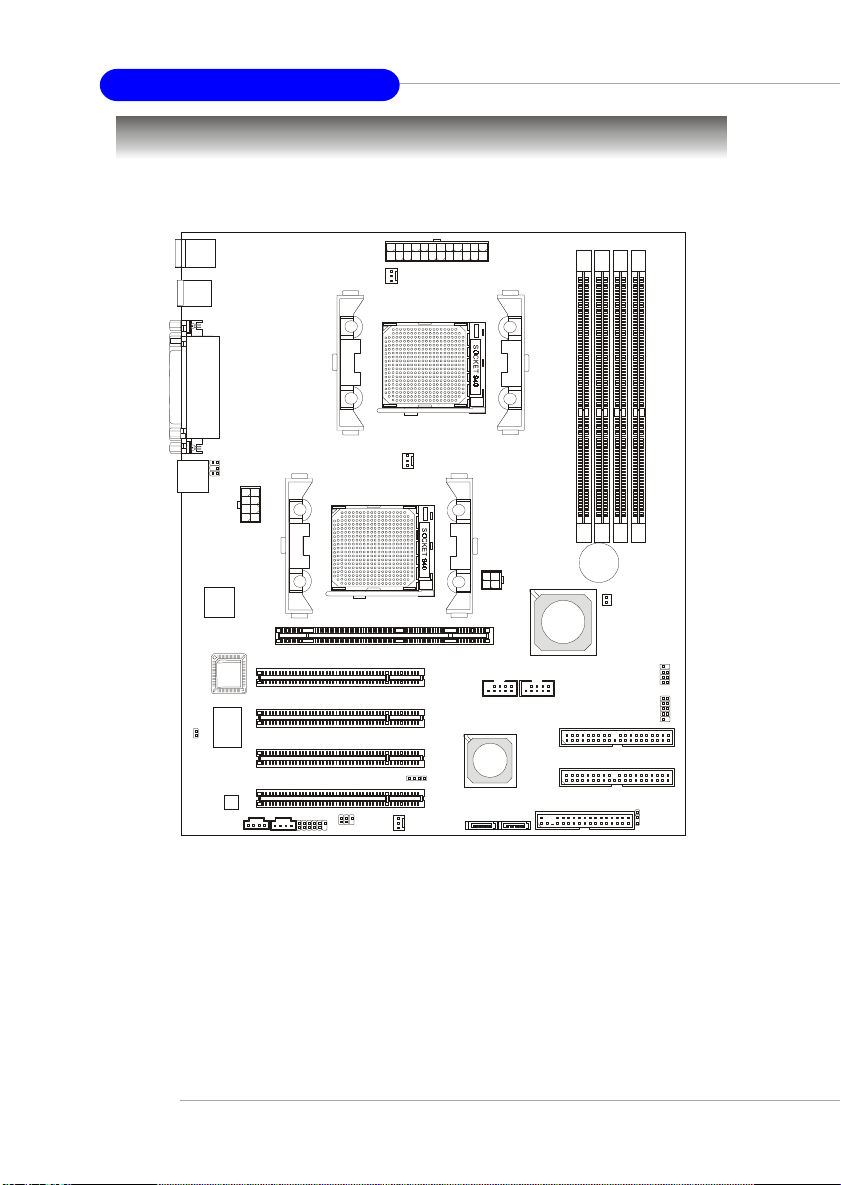
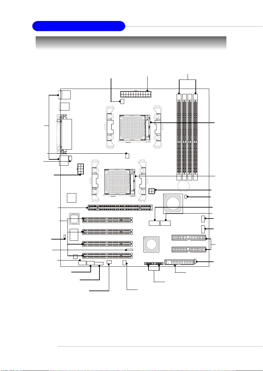
Mainboard Layout
Top : mouse
Bottom: keyboard
USB
ports
Top : Parall el Port
Bottom:
COM A
COM B
CFAN1
JPR1
4
3
2
1
R
R
R
R
D
D
D
D
D
D
D
D
LAN Jack
JCI1
JLCD1
Broadcom
5705
BIOS
Winbond
W83627THF
Codec
JPWR1
JCD1
JAUX1
PCI Slot 1
PCI Slot 2
PCI Slot 3
PCI Slot 4
JAUD1
AGP Pro Slot
JIR1
CFAN2
SFAN1
JPWR2
JUSB1 JUSB2
VIA
VT8237
J7
SATA2
SATA1
K8T Master2-FAR (MS-9130 v1.X) Mainboard
VIA
K8T 800
FDD 1
BATT
+
NBFAN1
JFP2
JFP1
IDE 1
IDE 2
JBAT1
1-4
Getting Started
MSI Special Features
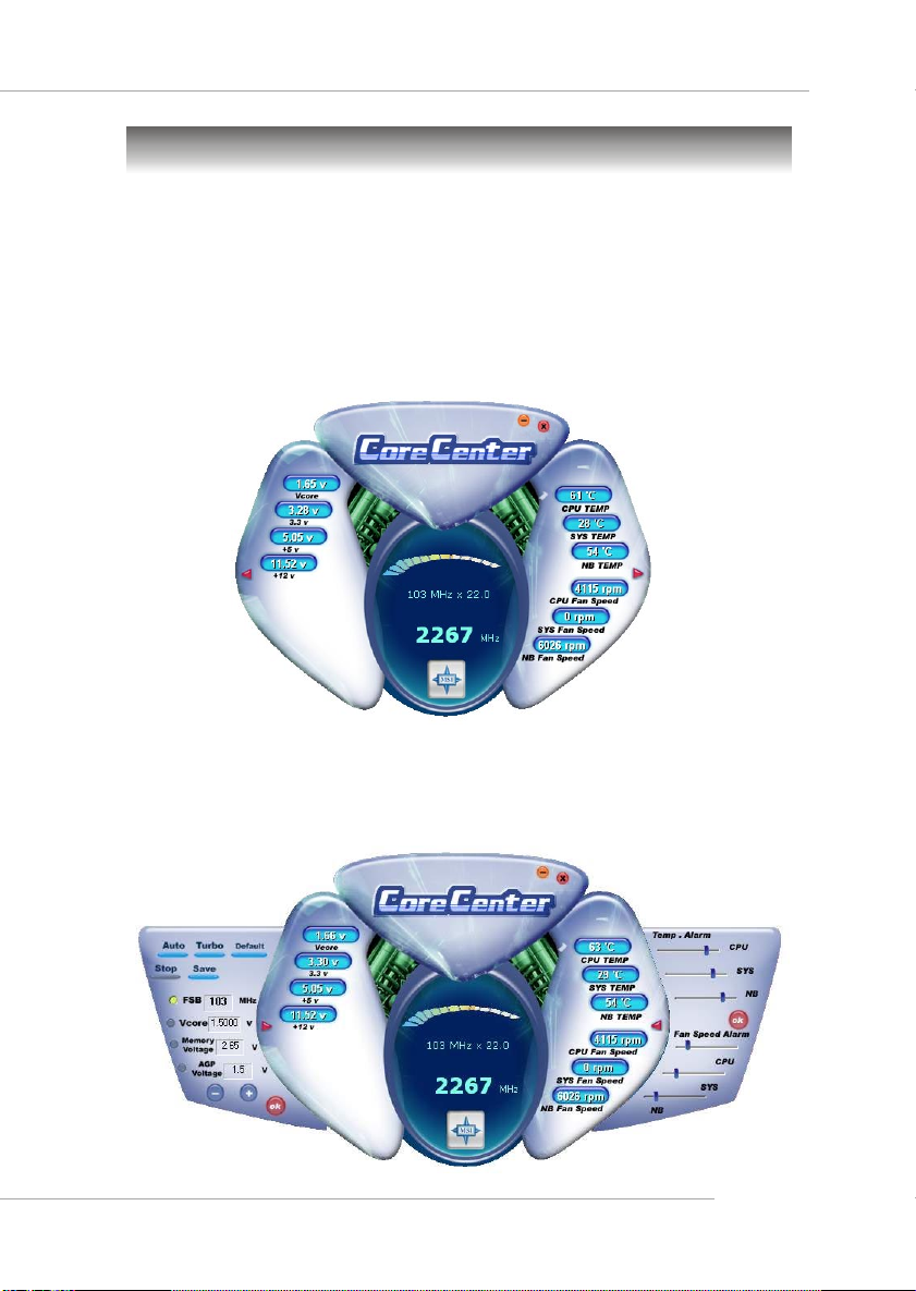
Core Center
The Core Center is a new utility you can find in the CD-ROM disk. The
utility is just like your PC doctor that can detect, view and adjust the PC
hardware and system status during real time operation. In the left side it shows
the current system status, including the Vcore, 3.3V, +5V and 12V. In the right
side it shows the current PC hardware status such as the CPU & system
temperatures and all fans speeds.
When you click the red triangles in the left and right sides, two submenus will open for users to overclock, overspec or to adjust the thresholds of
system to send out the warning messages. If you click the Core Center button
on the top, a screen pops up for you to choose the “Auto mode” or “User
mode” of CPU fan.
1-5

MS-9130 Workstation Mainboard
Left-side: Current system status
In the left sub-menu, you can configure the settings of FSB, Vcore,
Memory Voltage and AGP Voltage by clicking the radio button in front of each
item and make it available (the radio button will be lit as yellow when selected),
use the “+” and “-” buttons to adjust, then click “ok” to apply the changes.
Then you can click Save to save the desired FSB you just configured.
Also you may click Auto to start testing the maximal CPU overclocking
value, The CPU FSB will automatically increase the testing value until the PC
reboots. Or you may click Default to restore the default values.
Right-side: PC hardware status during real time operation
In the right sub-menu, here you can configure the PC hardware status
such as CPU & system temperatures and fan speeds. You may use the scroll
bars to adjust each item, then click “ok” to apply the changes. The values you
set for the temperatures are the maximum thresholds for the system for warnings,
and the value for fan speeds are the minimum thresholds.
T op-side: User mode/Auto mode
Here you may adjust the CPU fan speed. If you choose User mode, you
may adjust the CPU fan speed in 8 different modes, from Stop to Full speed.
1-6
MSI Reminds Y ou...
Items shown on Core Center vary depending on your system status.

Hardware Setup
Chapter 2. Hardware
Setup
Hardware Setup
This chapter provides you with the information about hardware setup procedures. While doing the installation, be careful
in holding the components and follow the installation
procedures. For some components, if you install in the wrong
orientation, the components will not work properly.
Use a grounded wrist strap before handling computer
components. Static electricity may damage the components.
2-1
MS-9130 Workstation Mainboard
Quick Components Guide
I/O Ports,
p.2-10
CFAN2, p.2-15
JLCD1,
p.2-15
JPWR1,
p.2-10
AGP1, p.2-22
PCI Slots, p.2-22
JCI1, p.2-20
J7, p.2-21
JCD1, p.2-21
JAUX1, p.2-21
JAUD1, p.2-19
JIR1, p.2-20
CFAN1, p.2-15
JPR1, p.2-9
SFAN1, p.2-15
DDR1~4, p.2-6
BATT
+
FDD1, p.2-14
SATA1/2, p.2-16
CPU1, p.2-3
CPU2, p.2-3
JPWR2, p.2-8
NBFAN1, p.2-15
JUSB1, p.2-20
JUSB2, p.2-20
JFP2, p.2-17
JFP1, p.2-17
IDE1/2,
p.2-14
JBAT1, p.2-21
2-2
Hardware Setup
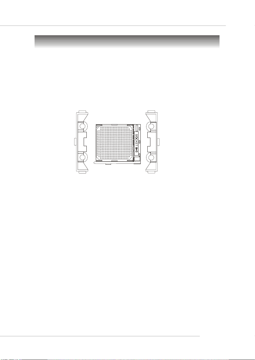
Central Processing Unit: CPU
The mainboard supports Single/Dual AMD® Opteron DP™ processor
(s). The mainboard uses two CPU sockets called Socket 940 for easy CPU
installation. Y ou can install SINGLE or DUAL CPUs on the mainboard to meet
your own needs. Keep the following points in mind before installing CPU(s):
1. If SINGLE CPU is intended, always install the CPU on the CPU1
socket.
CPU1 & CPU2
2. T o install DUAL CPUs on the board, you must use the same type of
CPUs running at the same frequency.
2-3
MS-9130 Workstation Mainboard
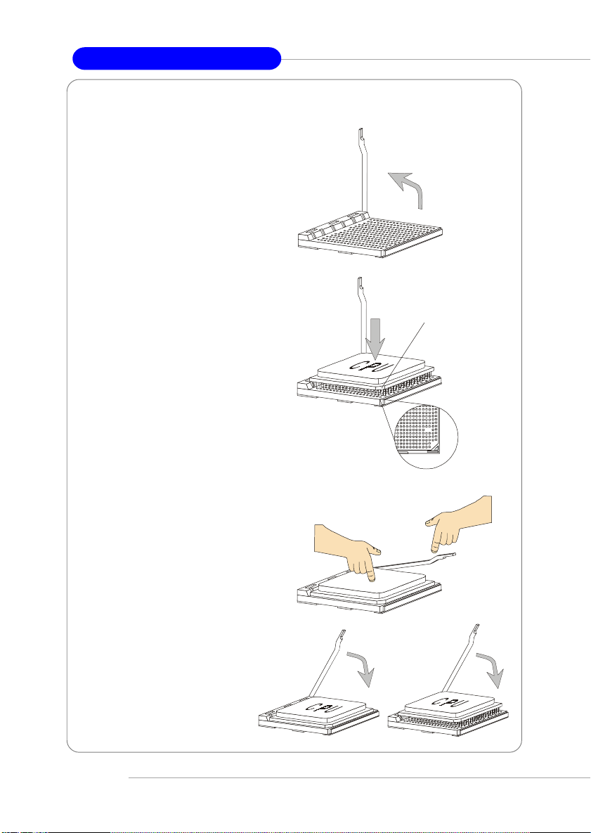
CPU Installation Procedures for Socket 940
1. Make sure that the computer
is turned off, and the power
cord disconnected before installing the CPU.
2. Pull the lever sideways away
from the socket, and raise it up
to a 90-degree angle.
3. Locate the cut edge of the
CPU. When the CPU is installed into the socket, this cut
edge should be aligned with
the corner marking an arrow on
the Socket 940.
Please note that the CPU can
only fit in a correct orientation,
DO NOT use force to install
the CPU into the socket.
4. Place the CPU onto the socket
and press it down firmly into
the socket. The pins of the
CPU should be embedded into
the socket completely.
g
n
i
d
i
l
S
Open Lever
e
t
a
l
P
Corner marking
an arrow
Press down
the CPU
Cut edge
Close
Lever
5. Close the lever to secure the
CPU. Do not close the level
until the CPU’s pins are fully
inserted; otherwise, the pins
may be damaged.
2-4
XO
Hardware Setup
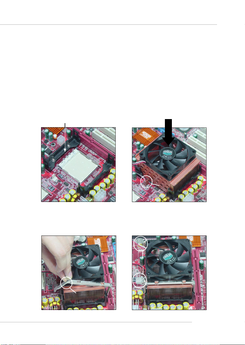
Installing the CPU heatsink/cooler
As processor technology pushes to faster speeds and higher
performance, thermal management becomes increasingly important. T o dissipate heat, you need to attach the CPU heatsink/cooler on top of the CPU.
Follow the instructions below to install the heatsink/cooler:
1. Locate the CPU and its retention mod-
ules on the motherboard.
retention modules
3. Hook one end of the clip into the hole
of the retention module, then push
down the handle to hook the other
end to the retention module.
2. Position the heatsink/cooler onto the
retention modules. Connect the wires
to the fan powers (CFAN1/CFAN2),
then press down the fan until its four
clips get wedged in the holes of the
retention modules.
fan power
4. Repeat step 3 on the other clip. Please
note the orientation of the handle of
heatsink/cooler for CFAN2 should be
the same as shown below to prevent
the intervention with AGP card.
handle
handle
2-5

MS-9130 Workstation Mainboard
Memory
The mainboard provides four slots for 184-pin DDR SDRAM DIMM
(Double In-Line Memory Module) modules and supports up to 4GB memory
size. Y ou can install PC2700/DDR333, PC2100/DDR266, or PC1600/DDR200
modules on the DDR DIMM slots (DDR 1~4).
DDR DIMM Slots
(DDR1~4)
Installing DDR Modules
1. The DDR DIMM has only one
notch on the center of module. The
module will only fit in the right
orientation.
2. Insert the DIMM memory module
vertically into the DIMM slot. Then
push it in until the golden finger
on the memory module is deeply
inserted in the socket.
3. The plastic clip at each side of the
DIMM slot will automatically
close.
2-6
Volt
Notch
Hardware Setup
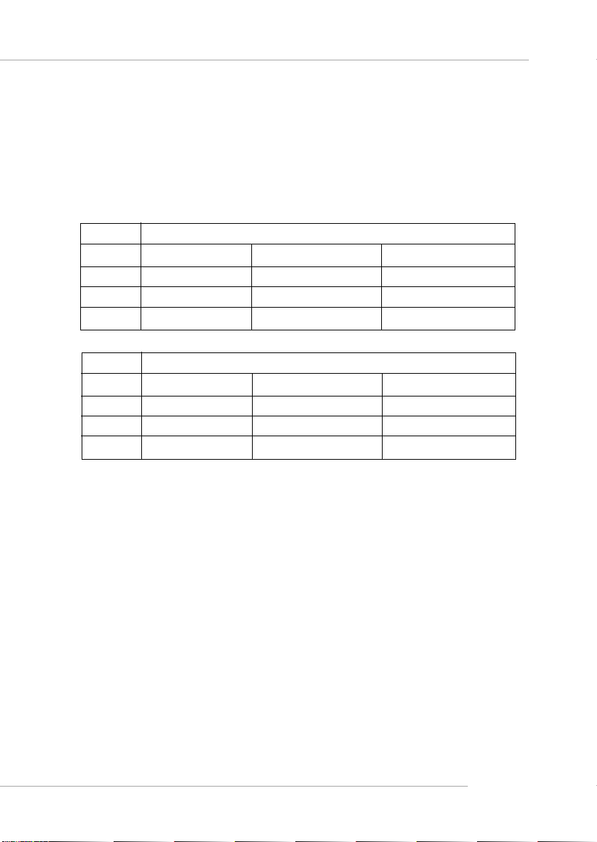
Memory Population Rules
The mainboard supports DDR333/266/200 memory interface.
Each DIMM slot supports up to a maximum size of 2GB. Users can install
either single- or double-sided modules depending on their needs.
Memory modules can be installed in any combination as follows:
Slot Memory Module Population Rules (Dual channel - 128 bits)
DIMM 1
DIMM 2
DIMM 3
DIMM 4
Slot Memory Module Population Rules (Single channel - 64 bits)
DIMM 1
DIMM 2
DIMM 3
DIMM 4
Install
Install
Install
Install
Install
Install
Install
Install
Install
Install
Install
Install
2-7
MS-9130 Workstation Mainboard
Power Supply
The mainboard supports SSI power supply for the power system, while
ATX power supply is also available for this mainboard. Before inserting the
power supply connector, always make sure that all components are installed
properly to ensure that no damage will be caused.
SSI 12V Power Connector: JPWR2
This connector is used to provide +12V power output to AGP Pro add-on
card.
3
1
2
4
JPWR2
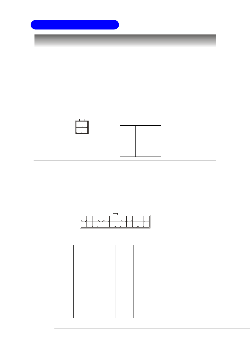
SSI 24-Pin Power Connector: JPR1
This connector allows you to connect an SSI power supply. To connect
the SSI power supply, make sure the plug of the power supply is inserted in the
proper orientation and the pins are aligned. Then push down the power supply firmly into the connector.
JPWR2 Pin Definition
PIN SIGNAL
1 GND
2 GND
3 12V
4 12V
2-8
JPR1
24 13
12
JPR1 Pin Definition
PIN SIGNAL
1 +3.3V
2 +3.3V
3 GND
4 +5V
5 GND
6 +5V
7 GND
8 PWR OK
9 5VSB
10 +12V
11 +12V
12 +3.3V
PIN SIGNAL
13 +3.3V
14 -12V
15 GND
16 PS-ON#
17 GND
18 GND
19 GND
20 Res
21 +5V
22 +5V
23 +5V
24 GND
1
Hardware Setup
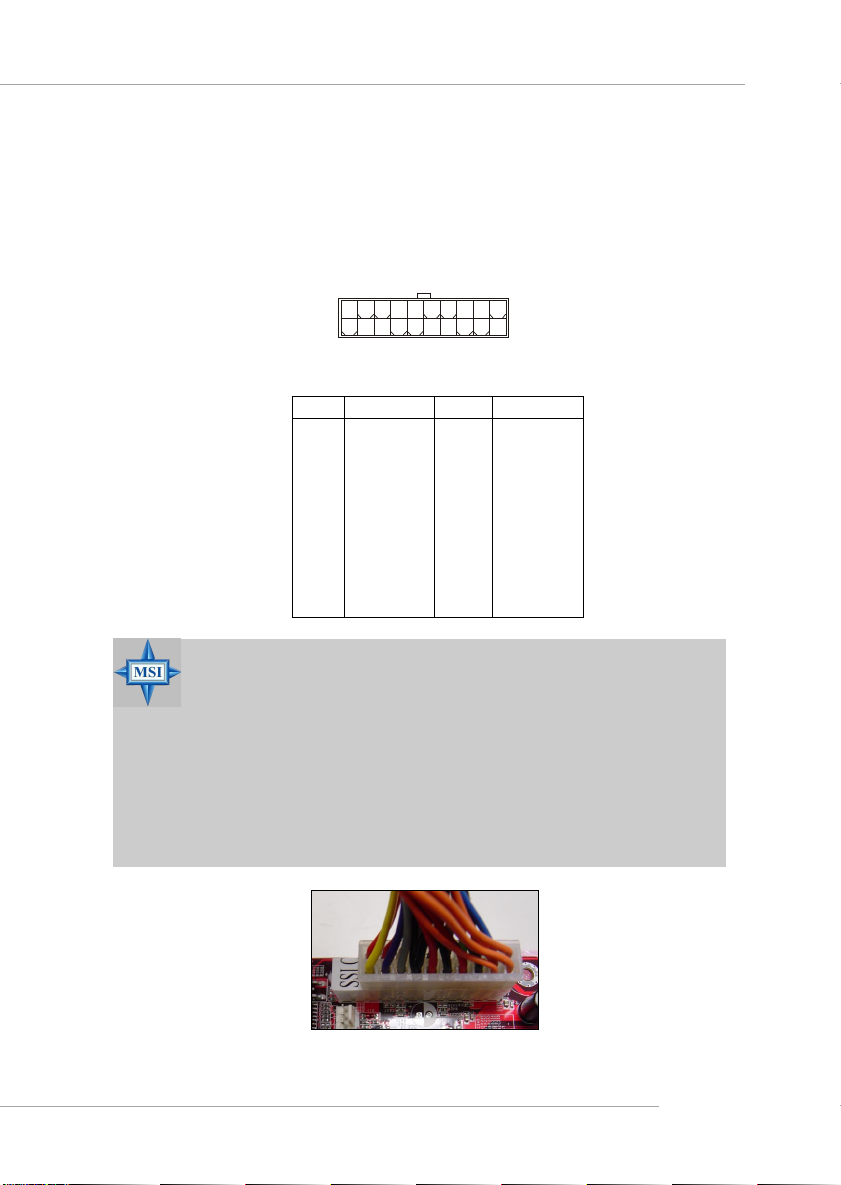
A TX 20-Pin Power Connector: A TX1
You may also choose to use ATX power supply. To connect to the ATX
power supply, make sure the plug of the power supply is inserted in the proper
orientation and the pins are aligned. Then push down the power supply firmly
into the connector.
20 11
10
ATX1 Pin Definition
PIN SIGNAL
1 3.3V
2 3.3V
3 GND
45V
5 GND
65V
7 GND
8 PW_OK
9 5V_SB
10 12V
ATX1
1
PIN SIGNAL
1 1 3.3V
12 -12V
13 GND
14 PS_ON
15 GND
16 GND
17 GND
18 -5V
19 5V
20 5V
MSI Reminds Y ou...
For this JPR1 power connector, you may use the 20-pin ATX power
supply or 24-pin SSI power supply as you like. If you’d like to use
the SSI power supply, please remove the sticker (covered the 11,
12, 23 and 24 pins, shown as the photo below) marked “SSI ONLY”
on the JPR1 power connector to insert the SSI power supply in the
proper orientation for correct alignment. If you’d like to use the
ATX power supply, please just insert your power supply in the rest
pins without removing the sticker.
2-9
MS-9130 Workstation Mainboard
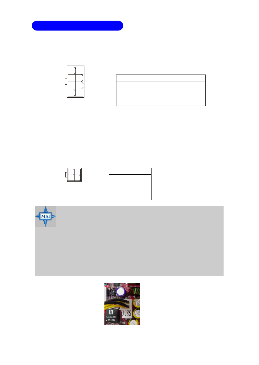
SSI 8-Pin Power Connector: JPWR1
This connector is used to provide the power output to the CPU.
8
5
JPWR1
4
1
JPWR1 Pin Definition
PIN SIGNAL
1 GND
2 GND
3 GND
4 GND
PIN SIGNAL
5 +12V
6 +12V
7 +12V
8 +12V
A TX 12V Power Connector: JPW1
You may also choose to use ATX 12V power supply. This 12V power
connector is used to provide power to the CPU.
42
13
JPW1
MSI Reminds Y ou...
For this JPWR1 power connector, you may use the 4-pin ATX
power supply or 8-pin SSI power supply as you like. If you’d like
to use the SSI power supply, please remove the sticker (covered
the 1, 2, 5 and 6 pins, shown as the photo below) marked “SSI
ONLY” on the JPWR1 power connector to insert the SSI power
supply in the proper orientation for correct alignment. If you’d
like to use the ATX power supply, please just insert your power
supply in the rest pins without removing the sticker.
JPW1 Pin Definition
PIN SIGNAL
1 GND
2 GND
3 12V
4 12V
2-10

Back Panel
View of the Back Panel
The back panel provides the following connectors:
Parallel
Hardware Setup
Mouse
USB
COM1 LAN
COM2
Keyboard
Mouse Connector
The mainboard provides a standard PS/2® mouse mini DIN connector
for attaching a PS/2® mouse. You can plug a PS/2® mouse directly into this
connector. The connector location and pin assignments are as follows.
Pin Definition
6
4
1
2
PS/2 Mouse
(6-pin Female)
5
3
PIN SIGNAL DESCRIPTION
1 Mouse Data Mouse data
2 NC No connection
3 GND Ground
4 VCC +5V
5 Mouse Clock Mouse clock
6 NC No connection
2-11
MS-9130 Workstation Mainboard
Keyboard Connector
The mainboard provides a standard PS/2® keyboard mini DIN connector
for attaching a PS/2® keyboard. You can plug a PS/2® keyboard directly into
this connecto. The connector location and pin assignments are as follows.
Pin Definition
6
4
1
2
PS/2 Keyboard
(6-pin Female)
5
3
PIN SIGNAL DESCRIPTION
1 Keyboard Data Keyboard data
2 NC No connection
3 GND Ground
4 VCC +5V
5 Keyboard Clock Keyboard clock
6 NC No connection
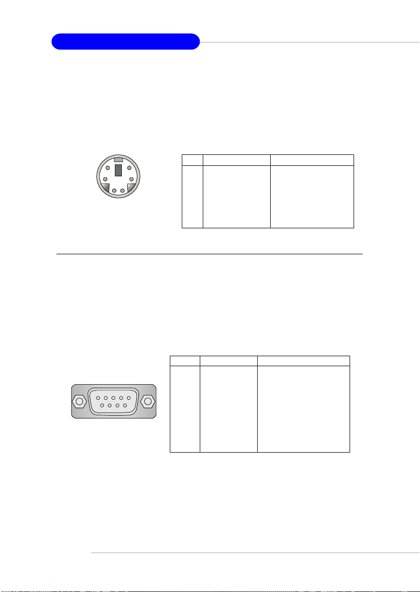
Serial Ports: COM1 & COM2
The mainboard provides two 9-pin mail DIN connectors as serial port
COM1 & COM2. The serial port is a 16550A high speed communication port
that sends/receives 16 bytes FIFOs. You can attach a serial mouse or other
serial device directly to it.
1 2 3 4 5
6 7 8 9
COM1 & COM2
2-12
Pin Definition
PIN SIGNAL DESCRIPTION
1 DCD Data Carry Detect
2 SIN Serial In or Receive Data
3 SOUT Serial Out or Transmit Data
4 DTR Data Terminal Ready
5 GND Ground
6 DSR Data Set Ready
7 RTS Request To Send
8 CTS Clear To Send
9 RI Ring Indicate
 Loading...