

Page 1

MP54GBT3 (MS-6855C)
Wireless 11g + Bluetooth
Combo MiniPCI Card
User’s Guide
i
Page 2

FCC Caution
1. The device complies with Part 15 of the FCC rules. Operation is subject to
the following two conditions:
(1) This device may not cause harmful interference, and
(2) This device must accept any interference received, including interference
that may cause undesired operation.
2. FCC RF Radiation Exposure Statement: The equipment complies with FCC
RF radiation exposure limits set forth for an uncontrolled environment.
This equipment should be installed and operated with a minimum
distance of 20 centimeters between the radiator and your body.
3. This Transmitter must not be co-located or operating in conjunction with
any other antenna or transmitter.
4. Changes or modifications to this unit not expressly approved by the
party responsible for compliance could void the user authority to operate
the equipment.
FCC Statement
This device is intended only for OEM integrators under the following
1) The antenna must be installed such that 20 cm is maintained between antenna
and users, and
2) The transmitter module may not be co-located with any other transmitter or
antenna.
As long as 2 conditions above are met, further transmitter test will not required. However,
the OEM integrator is still responsible for testing end-product for any additional compliance requirements required with module installed (for example, digital device emissions,
PC peripheral requirements, etc.).
Important Note
In the event that these conditions can not be example certain laptop configurations or colocation with another transmitter), then the FCC authorization is no longer considered
valid the FCC ID can not be used on the final product. In these circumstances, OEM
integrator will be responsible for re-evaluating the end product (including the transmitter)
and obtaining a separate FCC authorization.
ii
Page 3

End Product Labeling
This transmitter module is authorized only for use in device where antenna may be
installed such that 20 cm may be maintained between antenna and users (for example
access points, routers, wireless ADSL and similar equipment). The final end product
must be labeled in a area with the following: “ Contains TX FCC ID: I4L-MS6855C”.
Manual Information for End Users
The end user must not have manual instructions to remove or install device. The user
manual for end users must include the following information in a prominent location:
“IMPORTANT NOTE: To comply with FCC RF exposure compliance requirements,
the antenna used for this transmitter must be installed to provide a separation distance of
at least 20 cm from all persons and must not be co-located operating in conjunction with
any other antenna or transmitter.” as a result of e-mail transmission.”
Important Safety Precautions
Always read and follow these basic safety precautions carefully when handling any
piece of electronic component.
1. Keep this User’s Guide for future reference.
2. Keep this equipment away from humidity.
3. Lay this equipment on a reliable flat surface before setting it up.
4. The openings on the enclosure are for air convection hence protects the
equipment from overheating.
5. All cautions and warnings on the equipment should be noted.
6. Never pour any liquid into the opening that could damage or cause electrical
shock.
7. If any of the following situations arises, get the equipment checked by a
service personnel:
Liquid has penetrated into the equipment
The equipment has been exposed to moisture
The equipment has not work well or you can not get it work
according to User’s Manual
The equipment has dropped and damaged
If the equipment has obvious sign of breakage
8. DO NOT LEAVE THIS EQUIPMENT IN AN ENVIRONMENT
UNCONDITIONED, STORAGE TEMPERATURE ABOVE 60O C OR
BELOW -20OC, IT MAY DAMAGE THE EQUIPMENT.
iii
Page 4

Introduction
>>> 1.1 MP54GBT3 (MS-6855C) - Wireless 11g +
Bluetooth Combo MiniPCI Card
MSI MP54GBT3, the Wireless 11g + Bluetooth Combo miniPCI
Card, is a Type IIIB card, which can be used to integrate with
such systems as notebook, mini-barebone, PDA, portable PC.
With MSI MP54GBT3 embedded inside, a system could provide users with the ability and flexibility to connect up to Internet
wirelessly via 802.11g with speed up to 54Mbps, and to link
with peripherals wirelessly through BluetoothTM v2.0 and advanced EDR (Enhanced Data Rate) technology. Bluetooth
v2.0 technology increases the data rate of BluetoothTM v1.1/1.2
from 1.0Mbps to 2.1Mbps.
MSI MP54GBT3 is taking advantage of leading technologies
from Ralink and CSR. It addresses the co-existence issues in
PAN (Personal Area Network) and WLAN (Wireless Local Area
Network) markets by providing true simultaneous connectivity
while deploying IEEE 802.11g and Bluetooth v2.0 Along with
this combo solution, a system installed with a single card is able
to offer dual mode capability of WiFi and BluetoothTM. It will
benefit system vendors in miniaturization of system dimension
and BOM cost reduction, as well as also make users happy with
the all-in-one functionality.
TM
1
Page 5
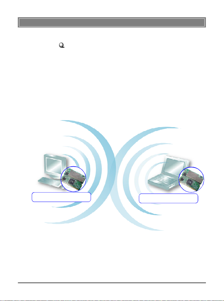
>>> 1.2 How MP54GBT3 Works
In WLAN Environment1.2.1
Ad-hoc Mode : An Ad-hoc network is a local area network or
other small network, especially one with wireless or temporary
plug-in connections, in which some of the network devices are
part of the network only for the duration of a communications
session. Users in the network can share files, print to a shared
printer, and access the Internet with a shared modem. In this
kind of network, new devices can be quickly added; however,
users can only communicate with other wireless LAN computers that are in this wireless LAN workgroup, and are within
range.
MP54GBT3
WLAN+Bluetooth Combo MiniPCI Card
MP54GBT3
WLAN+Bluetooth Combo MiniPCI Card
2
Page 6
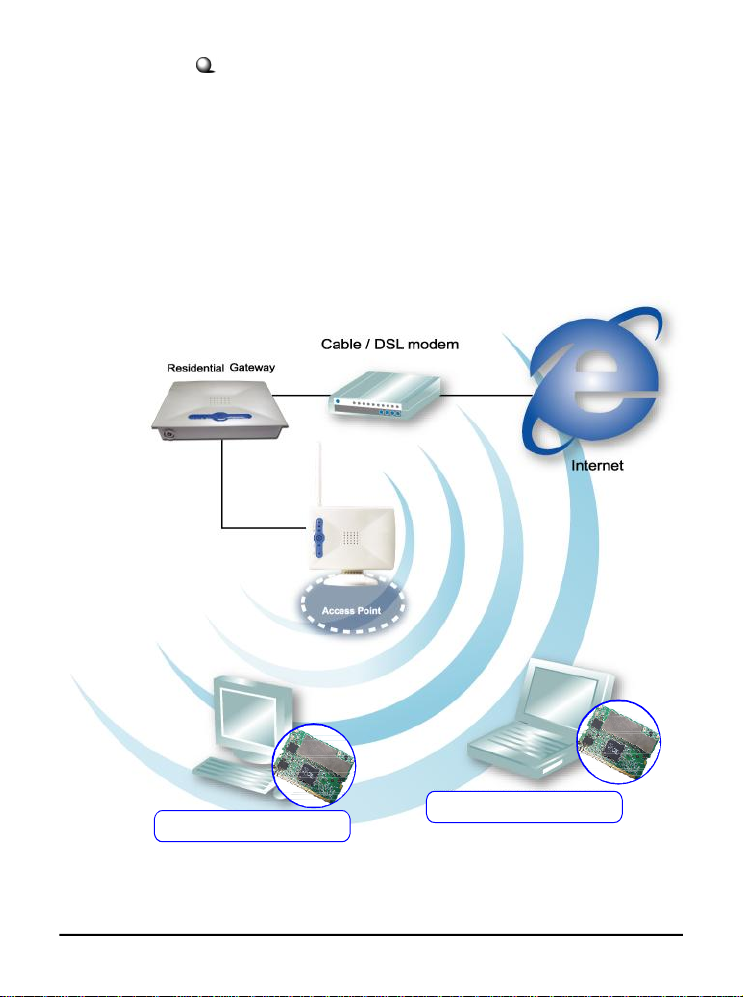
Infrastructure Mode : The difference between Infrastructure
network and Ad-hoc network is that the former one includes an
Access Point. In an Infrastructure network, the Access Point can
manage the bandwidth to maximize bandwidth utilization. Additionally, the Access Point enables users on a wireless LAN to
access an existing wired network, allowing wireless users to take
advantage of the wired networks resources, such as Internet,
email, file transfer, and printer sharing. The scale and range of the
Infrastructure networking are larger and wider than that of the
Ad-hoc networking.
MP54GBT3
WLAN+Bluetooth Combo MiniPCI Card
MP54GBT3
WLAN+Bluetooth Combo MiniPCI Card
3
Page 7
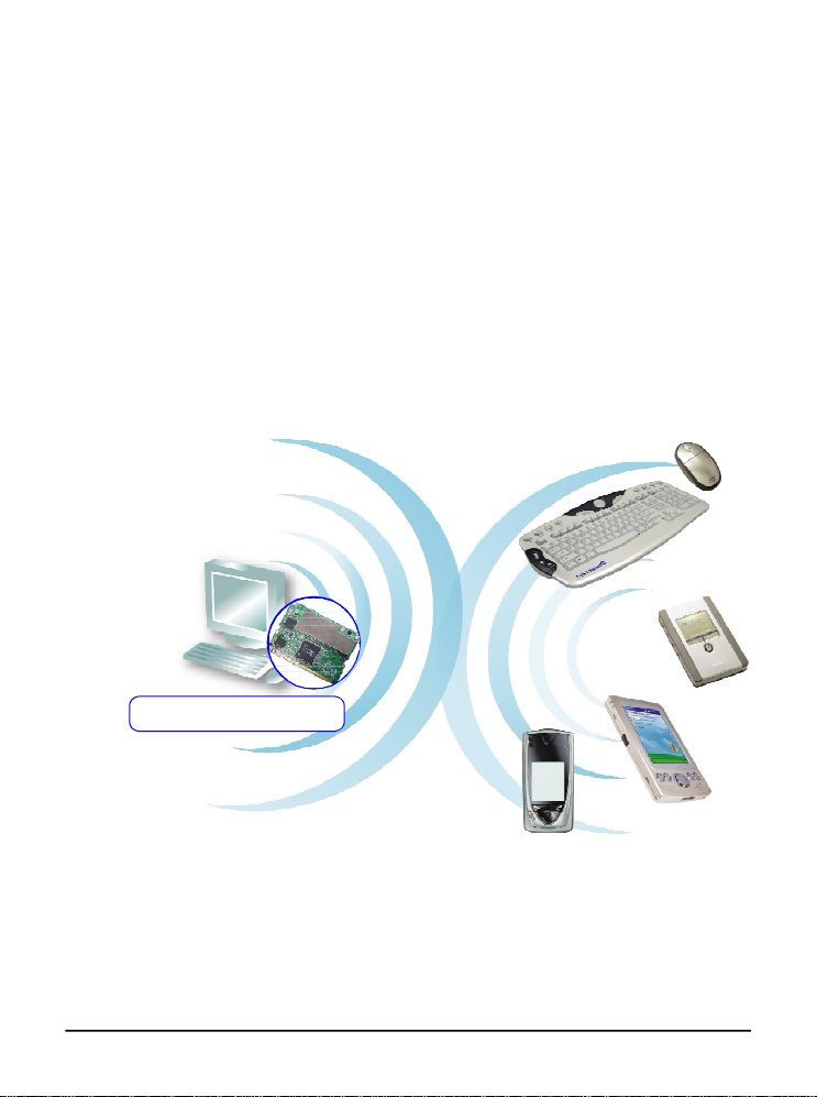
In Bluetooth Connection
1.2.2
The term “Bluetooth” refers to a worldwide standard for the
wireless exchange of data between two devices. In order to exchange data, two Bluetooth devices must establish a connection.
Before a connection is established, one device must request a
connection with another. The second device accepts (or rejects)
the connection. The originator of the request is known as the
client. The device that accepts (or rejects) the request is known
as the server. Many Bluetooth devices can act as both client and
server. Every Bluetooth device that provides a service must be
prepared to respond to a connection request. Bluetooth software is always running in the background on the server, ready to
respond to connection requests.
MP54GBT3
WLAN+Bluetooth Combo MiniPCI Card
Bluetooth-enabled Devices
4
Page 8

>>> 1.3 Specifications
Hardware
Specification
WLAN
Specification
Form Factor 32-bit Type IIIB
Operation voltage 3.3V
Antenna Connector Two antenna connectors
Operating System Microsoft® Windows® 98SE/ME/2000
/XP/XP-64bit
Environmental - Operating Temperature:
0 ~ 55OC
- Operating Humidity:
10 ~ 90%, non-condensing
Dimensions (WxDxH)59.75 x 44.6 x 3.5mm
Network Standard IEEE 802.11; IEEE 802.11b/g
Frequency Band 2.412-2.484 GHz
Data Rate IEEE 802.11g (auto-fallback):
- OFDM: 54, 48, 36, 24, 18, 12, 9 and
6Mbps
IEEE 802.11b (auto-fallback):
- CCK: 11, 5.5 Mbps
- DQPSK: 2 Mbps
- DBPSK: 1 Mbps
Media Access ControlCSMA/CA with ACK
Transmission DSSS (direct sequential spread
spectrum)
Network ArchitectureAd-Hoc Mode (Peer-to-Peer);
Infrastructure Mode
Antenna Type Two antenna connectors support
Power Consumption TX peak: 310mA RX peak: 250mA
Standby mode: 150mA
5
Page 9

Channel IEEE 802.11g:Ch. 1-11 – N. America
Ch. 1-13 – Japan
Ch. 1-13– Europe ETSI
Ch. 10-11 – Spain
Ch. 10-13 – France
IEEE 802.11b:Ch. 1-11 – N. America
Ch. 1-13 – Japan
Ch. 1-13– Europe ETSI
Ch. 10-11 – Spain
Ch. 10-13 – France
Output Power Output Power(Before Antenna)
11b: 17dBm+/-2 Max
11g: 14.5dBm+/-1 Max
Receiver Sensitivity 54 Mbps OFDM @ 10% PER = -65 dBm
(Average Value) 48 Mbps OFDM @ 10% PER = -66 dBm
36 Mbps OFDM @ 10% PER = -70 dBm
24 Mbps OFDM @ 10% PER = -74 dBm
18 Mbps OFDM @ 10% PER = -77 dBm
12 Mbps OFDM @ 10% PER = -79 dBm
11 Mbps CCK @ 8% PER = -80 dBm
9 Mbps OFDM @ 10% PER = -81 dBm
6 Mbps OFDM @ 10% PER = -82 dBm
5.5 Mbps CCK @ 8% PER = -82 dBm
2 Mbps QPSK @ 8% PER = -83 dBm
1 Mbps BPSK @ 8% PER = -83 dBm
6
Page 10

Bluetooth
Specification
Network Standard Bluetooth v2.0 (Class II) +EDR
Frequency Band 2.4-2.483 GHz
Data Rate Up to 2.1Mbps
Channel 79 sub-channels
Transmission FHSS (Frequency Hopping Spread
Spectrum)
Modulation GFSK
Antenna Type One antenna connector support
Power Consumption 66 mA (maximum, continuous TX)
Max. Output Power Up to 2dBm
Max. Input Level 0dBm
Receiver Sensitivity -70dBm @ BER<0.1%
Range Up to 10 m
Physical Links Support ACL link
Network Capabilities Support piconet point-to-point and
point-to multipoint connections
Link Manager 3-slot Packets: Yes
5-slot Packets: Yes
Slot Offset: Yes
Timing Accuracy: Yes
Switch: Yes
Hold Mode: Yes
Sniff Mode: Yes
Test Mode: Yes
Park Mode: Yes
RSSI: Yes
Power Control: Yes
Authentication: Yes
Encryption: Yes
7
Page 11
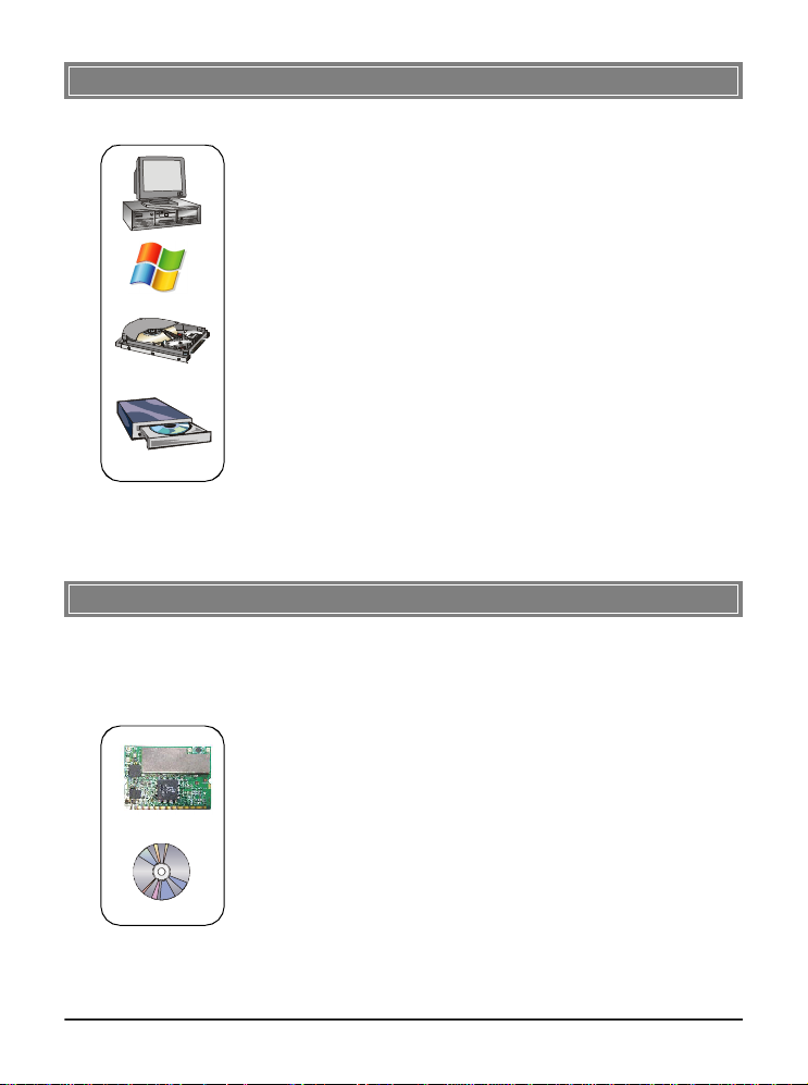
>>> 1.4 System Requirements
Before installing MP54GBT3, your PC should meet the following items:
- One desktop/notebook PC with an available MiniPCI slot.
- Windows® 98SE/ME/2000/XP/XP 64bit operating system.
- Minimum 5MB free disk space for installing the driver and
utilities.
- One CD-ROM drive, double speed or higher.
>>> 1.5 Package Contents
Unpack the package and check all the items carefully. If any item
contained is damaged or missing, please contact your local dealer
as soon as possible. Also, keep the box and packing materials in
case you need to ship the unit in the future. The package should
contain the following items:
- One Wireless 11g + Bluetooth Combo MiniPCI Card.
- One Installation CD-ROM including drivers, utilities, and the
manual files.
8
Page 12
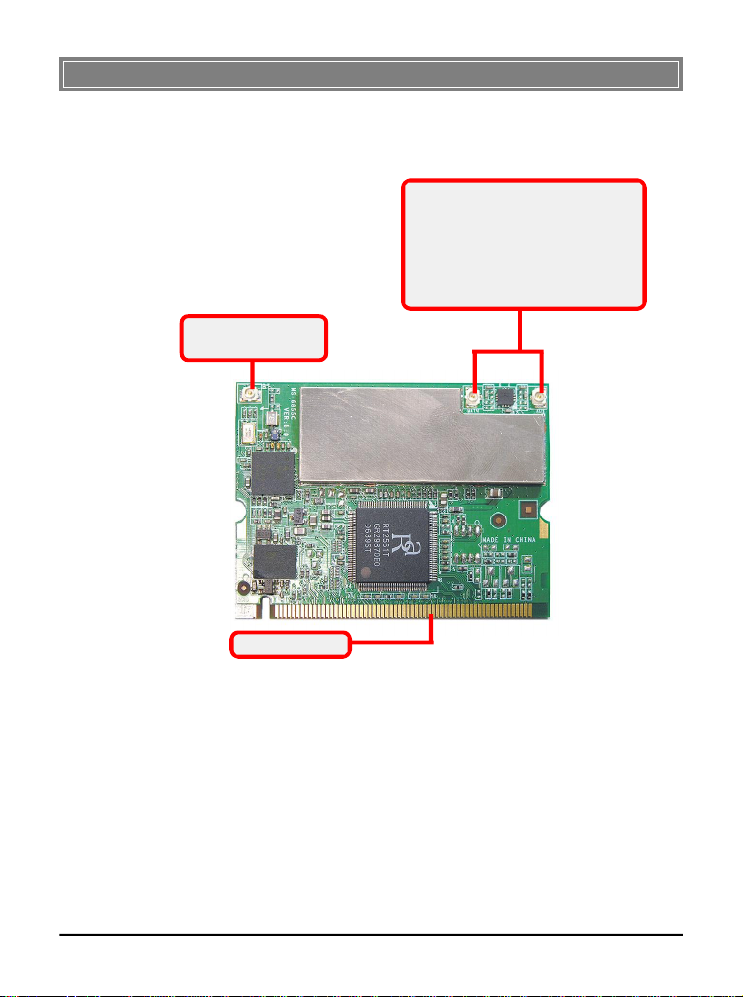
>>> 1.6 Product View
Bluetooth antenna
Connector
Golden Finger
WLAN 11g antenna connectors
Connect to external antennas for
enhanced data transmission and
reception. The external antennas are
well designed on the desktop or notebook computers.
9
Page 13
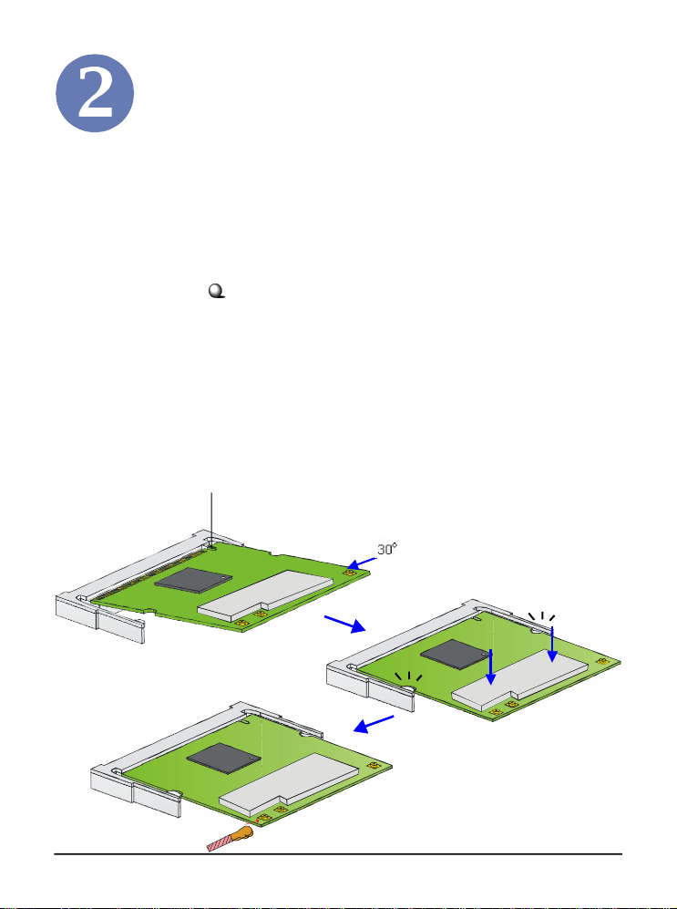
Hardware Installation
The following diagrams provide you a basic installation for your
MP54GBT3. The instruction below is suitable for most computers with MiniPCI slot. For more information about the
MiniPCI module, please refer to your computer’s manual.
Installing MP54GBT3:
1. Locate the MiniPCI slot on the mainboard.Place your
MP54GBT3 over the MiniPCI slot (at an angle of 30
degrees). Then, gently insert it into the slot until the
golden finger of the card gets fully inserted.
2. Press down the card, and the retaining clips (on two
sides of the slot) will lock onto the notches of the card.
3. Connect the attenna’s cable to the connector on the card.
Foolproof notch
10
Page 14
Software Installation
This chapter describes the procedures of installing the driver
and utility. Follow the instruction step by step to finish the
installation. If you use Windows® 98SE/ME, please prepare
the Windows® Setup CD at hand before installing the driver;
because the system will ask you to insert the Setup CD to copy
files during the installation.
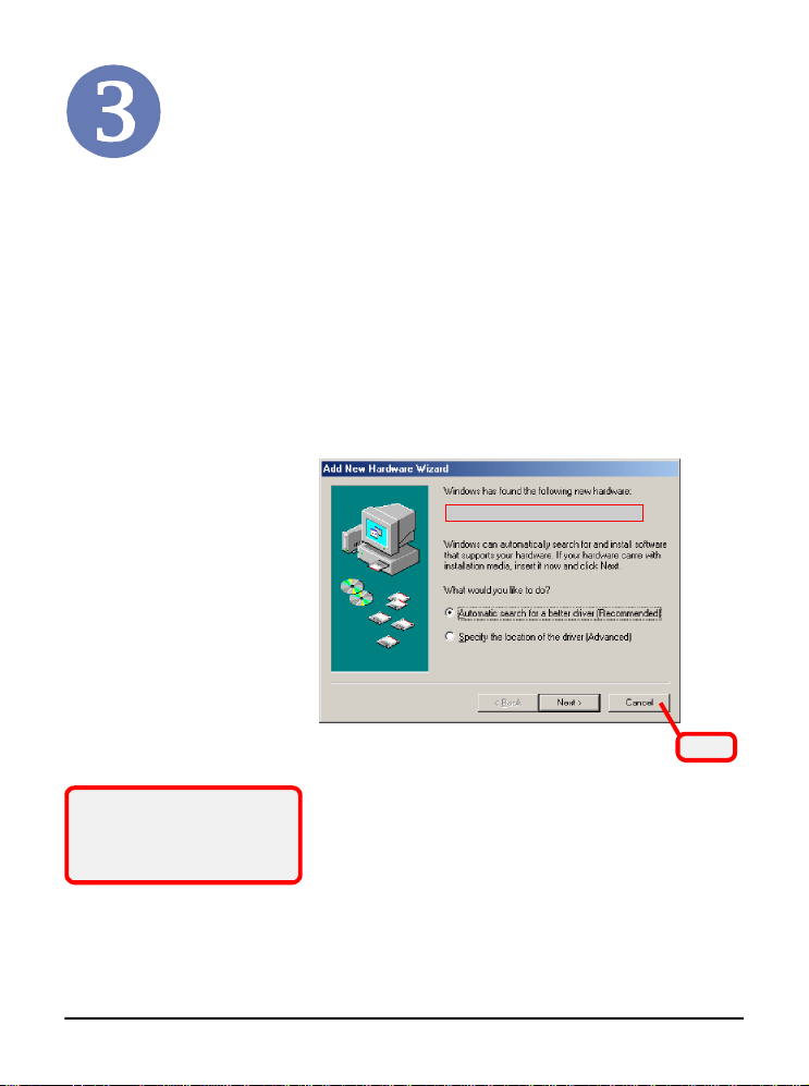
Please NOTE that the MP54GBT3 should be installed into
your computer before installing the driver and utility. Then,
the operating system will detect a new device and start to configure the new device. Click Cancel here to start installation
from the InstallShield Wizard.
The adapter model you installed
Click
Tip: The MP54GBT3 adapter
should be installed into your PC
before installing the driver and
utility.
11
Page 15
STEP
1
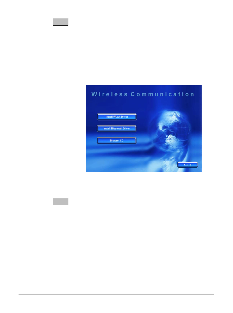
Insert the software CD into your CD-ROM drive, and the Setup
program should launch automatically.
If the Autorun program doesn’t launch automatically, click Start
at the taskbar and select Run.... Type E:\setup.exe (where E is
your CD-drive) in the Open box and click OK to launch the
Setup program manually.
The main screen of Setup program will appear as below.
STEP
2
1. Click the Install WLAN Driver button.
2. The welcome screen of InstallShield Wizard appears.
Click Next.
3. Read and accept the License Agreement; then, click Next.
4. Click Install and the program will copy the necessary
files to the system. The progress indicator shows the
installing status.
5. Click Finish when the WLAN driver installation is
completed.
12
Page 16
STEP
3
1. Click the Install Bluetooth Driver button.
2. The welcome screen of InstallShield Wizard appears.
Click Next.
3. Read and accept the License Agreement; then, click Next.
4. Click Next to install the driver in the default destination
folder.
5. Click Install and the program will copy the necessary
files to the system. The progress indicator shows the
installing status.
6. Click Finish when the bluetooth driver installation is
completed.
STEP
4
Click the Exit button.
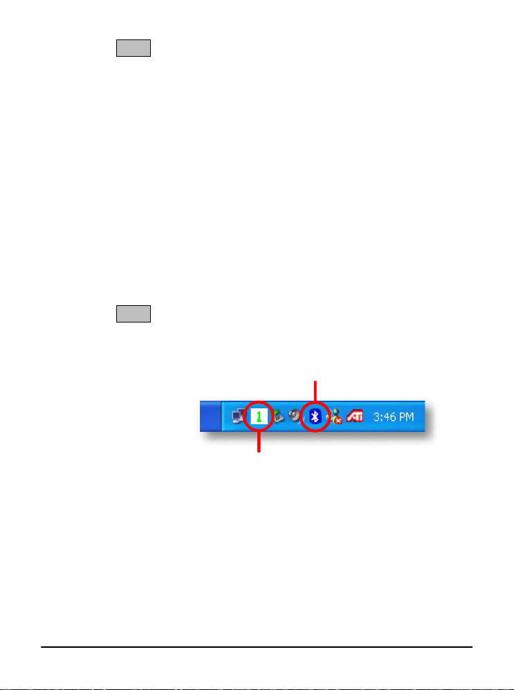
The Wireless LAN icon and Bluetooth icon will appear in the
status bar.
Bluetooth icon
Wireless LAN icon
13
Page 17

Preface
General Introductions Chapter 1
Chapter 2
Getting Started
Chapter 3
Customizing this Notebook
Chapter 4
BIOS setup
Page 18

Regulations Information
FCC-B Radio Frequency Interference Statement
This equipment has been tested and found to comply with the limits for a Class B
digital device, pursuant to part 15 of the FCC rules. These limits are designed
to provide reasonable protection against harmful interference in a residential
installation. This equipment generates uses and can radiate radio frequency
energy and, if not installed and used in accordance with the instructions, may
cause harmful interference to radio communications. However, there is no
guarantee that interference will not occur in a particular installation. If this
equipment does cause harmful interference to radio or television reception,
which can be determined by turning the equipment off and on, the user is
encouraged to try to correct the interference by one or more of the following
measures:
w Reorient or relocate the receiving antenna.
Preface
w Increase the separation between the equipment and receiver.
w Connect the equipment into an outlet on a circuit different from that to
which the receiver is connected.
w Consult the dealer or an experienced radio TV technician for help.
NOTE
1. The changes or modifications not expressly approved by the party
responsible for compliance could void the user’s authority to operate the
equipment.
2. Shield interface cables and AC power cord, if any must be used in order
to comply with the emission limits.
II
Page 19

FCC Conditions
This device complies with part 15 of the FCC Rules. Operation is subject to the
following two conditions:
1. This device may not cause harmful interference.
2. This device must accept any interference received, including
interference that may cause undesired operation.
Preface
III
Page 20
fabrikat og type.
(English) CAUTION: Danger of explosion if battery is incorrectly replaced.
, jos se on virheellisesti asennettu.
abrikanten.
batterityp eller en ekvivalent typ som rekommenderas av apparattillverkaren.
Safety Guideline for Using Lithium Battery
(Danish) ADVARSEL! Lithiumbatteri --- Eksplosionsfare ved fejlagtig
håndtering. Udskiftning må kun ske med batteri af same
Levé det brugte batteri tilbage til leverandøren.
(Deutsch) VORSICHT: Explosionsgefahr bei unsachgemäßem Austausch der
Batterie. Ersatz nur durch denselben oder einen vom Hersteller empfohlenen
gleich-wertigen Typ. Entsorgung gebrauchter Batterien nach Angaben des
Herstellers.
Replace only with the same or equivalent type recommended by the equipment
manufacturer. Discard used batteries according to manufacturer’s instructions.
(Finnish) VAROITUS: Paristo voi räjähtää
Vaihda paristo ainoastaan valmistajan suosittelemaan tyyppiin. Hävitä käytetty
paristo valmistajan ohjeiden mukaisesti.
Preface
(French) ATTENTION: II y a danger d’ex;losion s’il y a remplacement incorrect
de la batterie. Remplacer uniquement avec une batterie du meme type ou d’un
type équivalent recommandé par le constructeur. Mettre au rebut les batteries
usages conformément aux instructions du fabricant.
(Norwegian) ADVARSEL: Eksplosjonsfare ved feilaktig skifte av batteri. Benytt
same batteritype eller en tilsvarende type anbefalt av apparatf
Brukte batterier kasseres I henhold til fabrikantens instruksjoner.
(Swedish) VARNING: Explosionsfara vid felaktigt batteribyte. Använd samma
Kassera använt batteri enligt fabrikantens instruction.
IV
Page 21

Caution on Using Modem
1. Never install telephone wiring during a lightning storm.
2. Never install telephone jacks in wet locations unless the jack is specifically
designed for wet locations.
3. Never touch uninsulated telephone wires or terminals unless the telephone
line has been disconnected at the network interface.
4. Use caution when installing or modifying telephone lines.
5. Avoid using the telephone function (other than a cordless type) during an
electrical storm. There may be a remote risk of electric shock from
lightning.
6. Do not use the telephone function to report a gas leak in the vicinity of the
leak.
Preface
CD-ROM Drive Notice
CAUTION: This appliance contains a laser system and is classified as a
“CLASS 1 LASER PRODUCT.” To use this model properly, read the
instruction manual carefully and keep this manual for your future reference.
In case of any trouble with this model, please contact your nearest
“AUTHORIZED service station.” To prevent direct exposure to the laser
beam, do not try to open the enclosure.
V
Page 22

Macrovision Notice
This product incorporates copyright protection technology that is protected
by U.S. patents and other intellectual property rights. Use of this copyright
protection technology must be authorized by Macrovision, and is intended
for home and other limited viewing uses only unless otherwise authorized
by Macrovision. Reverse engineering or disassembly is prohibited.
Safety Instructions
1. Read the safety instructions carefully and thoroughly.
2. Save this User Guide for possible use later.
3. Keep this equipment away from humidity and high temperature.
4. Lay this equipment on a stable surface before setting it up.
Preface
5. The openings on the enclosure are used for air convection and to prevent
the equipment from overheating. Do not cover the openings.
6. Make sure that the power voltage is within its safety range and has been
adjusted properly to the value of 100~240V before connecting the
equipment to the power inlet.
7. Place the power cord in a way that people are unlikely to step on it. Do
not place anything on the power cord.
8. Always unplug the power cord before inserting any add-on card or module.
9. All cautions and warnings on the equipment should be noted.
10. If any of the following situations arises, get the equipment checked by a
service personnel:
VI
Page 23

w The power cord or plug is damaged.
w Liquid has penetrated into the equipment.
w The equipment has been exposed to moisture.
w The equipment has not worked well or you can not get it work
according to User’s Manual.
w The equipment was dropped and damaged.
w The equipment has obvious signs of breakage.
11. Never pour any liquid into the opening that could damage the equipment or
cause an electrical shock.
12. Do not leave the equipment in an unconditioned environment with a
storage temperature of 35OC (95OF) or above, which may damage the
equipment.
13. To prevent explosion caused by improper battery replacement, use the
same or equivalent type of battery recommended by the manufacturer only.
Preface
VII
Page 24

WEEE Statement
(English) Under the European Union ("EU") Directive on Waste Electrical and
Electronic Equipment, Directive 2002/96/EC, which takes effect on August 13,
2005, products of "electrical and electronic equipment" cannot be discarded as
municipal waste anymore and manufacturers of covered electronic equipment
will be obligated to take back such products at the end of their useful life.
(Deutsch) Gemäß der Richtlinie 2002/96/EG über Elektro- und
Elektronik-Altgeräte dürfen Elektro- und Elektronik-Altgeräte nicht mehr als
kommunale Abfälle entsorgt werden, die sich auf 13.August, 2005 wirken. Und
der Hersteller von bedeckt Elektronik-Altgeräte gesetzlich zur gebrachten
Produkte am Ende seines Baruchbarkeitsdauer zurückzunehmen.
(Français) Au sujet de la directive européenne (EU) relative aux déchets des
Preface
équipement électriques et électroniques, directive 2002/96/EC, prenant effet le
13 août 2005, que les produits électriques et électroniques ne peuvent être
déposés dans les décharges ou tout simplement mis à la poubelle. Les
fabricants de ces équipements seront obligés de récupérer certains produits en
fin de vie.
(Русский) В соответствии с директивой Европейского Союза (ЕС) по
предотвращению загрязнения окружающей среды использованным
электрическим и электронным оборудованием (директива WEEE
2002/96/EC), вступающей в силу 13 августа 2005 года, изделия,
относящиеся к электрическому и электронному оборудованию, не могут
VIII
Page 25

рассматриваться как бытовой мусор, поэтому производители
вышеперечисленного электронного оборудования обязаны принимать его
для переработки по окончании срока службы.
(Español) Bajo la directiva 2002/96/EC de la Unión Europea en materia de
desechos y/o equipos electrónicos, con fecha de rigor desde el 13 de agosto
de 2005, los productos clasificados como "eléctricos y equipos electrónicos"
no pueden ser depositados en los contenedores habituales de su municipio,
los fabricantes de equipos electrónicos, están obligados a hacerse cargo de
dichos productos al termino de su período de vida.
(Nederlands) De richtlijn van de Europese Unie (EU) met betrekking tot
Vervuiling van Electrische en Electronische producten (2002/96/EC), die op 13
Augustus 2005 in zal gaan kunnen niet meer beschouwd worden als vervuiling.
Fabrikanten van dit soort producten worden verplicht om producten retour te
nemen aan het eind van hun levenscyclus..
Preface
(Srpski) Po Direktivi Evropske unije ("EU") o odbačenoj ekektronskoj i
električnoj opremi, Direktiva 2002/96/EC, koja stupa na snagu od 13. Avgusta
2005, proizvodi koji spadaju pod "elektronsku i električnu opremu" ne mogu
više biti odbačeni kao običan otpad i proizvođači ove opreme biće prinuđeni da
uzmu natrag ove proizvode na kraju njihovog uobičajenog veka trajanja.
(Polski) Zgodnie z Dyrektywą Unii Europejskiej ("UE") dotyczącą odpadów
produktów elektrycznych i elektronicznych (Dyrektywa 2002/96/EC), która
wchodzi w życie 13 sierpnia 2005, tzw. “produkty oraz wyposażenie
elektryczne i elektroniczne " nie mogą być traktowane jako śmieci komunalne,
tak więc producenci tych produktów będą zobowiązani do odbierania ich w
IX
Page 26

momencie gdy produkt jest wycofywany z użycia.
(TÜRKÇE) Avrupa Birliği (AB) Kararnamesi Elektrik ve Elektronik Malzeme
Atığı, 2002/96/EC Kararnamesi altında 13 Ağustos 2005 tarihinden itibaren
geçerli olmak üzere, elektrikli ve elektronik malzemeler diğer atıklar gibi çöpe
atılamayacak ve bu elektonik cihazların üreticileri, cihazların kullanım süreleri
bittikten sonra ürünleri geri toplamakla yükümlü olacaktır.
(ČESKY) Podle směrnice Evropské unie ("EU") o likvidaci elektrických a
elektronických výrobků 2002/96/EC platné od 13. srpna 2005 je zakázáno
likvidovat "elektrické a elektronické výrobky" v běžném komunálním odpadu a
výrobci elektronických výrobků, na které se tato směrnice vztahuje, budou
povinni odebírat takové výrobky zpět po skončení jejich životnosti.
(MAGYAR) Az Európai Unió („EU") 2005. augusztus 13-án hatályba lépő, az
elektromos és elektronikus berendezések hulladékairól szóló 2002/96/EK
irányelve szerint az elektromos és elektronikus berendezések többé nem
Preface
kezelhetőek lakossági hulladékként, és az ilyen elektronikus berendezések
gyártói kötelessé válnak az ilyen termékek visszavételére azok hasznos
élettartama végén.
(Italiano) In base alla Direttiva dell’Unione Europea (EU) sullo Smaltimento dei
Materiali Elettrici ed Elettronici, Direttiva 2002/96/EC in vigore dal 13 Agosto
2005, prodotti appartenenti alla categoria dei Materiali Elettrici ed Elettronici
non possono più essere eliminati come rifiuti municipali: i produttori di detti
materiali saranno obbligati a ritirare ogni prodotto alla fine del suo ciclo di vita..
X
Page 27

Trademarks
All trademarks are the properties of their respective owners.
w Microsoft is a registered trademark of Microsoft Corporation.
Windows®98/ME, 2000/XP are registered trademarks of Microsoft
Corporation.
w AMI® is a registered trademark of American Megatrends Inc.
w PCMCIA and CardBus are registered trademarks of the Personal
Notebook Memory Card International Association.
Release History
Version Revision Note Date
1.0 First Release 03, 2006
Preface
XI
Page 28

Table of Content
Preface
Regulations Information.....................................................................................II
FCC-B Radio Frequency Interference Statement........................................II
FCC Conditions............................................................................................III
Safety Guideline for Using Lithium Battery....................................................IV
Caution on Using Modem...................................................................................V
CD-ROM Drive Notice..........................................................................................V
Macrovision Notice.............................................................................................VI
Safety Instructions.............................................................................................VI
WEEE Statement...............................................................................................VIII
Trademarks..........................................................................................................XI
Preface
Release History...................................................................................................XI
Introductions
How to Use This Manual..................................................................................1-2
Unpacking..........................................................................................................1-4
Getting Started
Specification......................................................................................................2-2
Product Overview.............................................................................................2-5
XII
Page 29

Top-open View............................................................................................2-5
Front View...................................................................................................2-7
Left-side View...........................................................................................2-10
Right-side View.........................................................................................2-12
Rear View.................................................................................................2-14
Bottom View..............................................................................................2-15
Power Management........................................................................................2-17
AC Adapter................................................................................................2-17
Battery Pack.............................................................................................2-18
Using the Battery Pack.............................................................................2-21
Basic Operations............................................................................................2-23
Safety and Comfort Tips...........................................................................2-23
Have a Good Work Habit.........................................................................2-24
Knowing the Keyboard.............................................................................2-25
Preface
Knowing the Touchpad.............................................................................2-31
About Hard Disk Drive..............................................................................2-35
Using the Optical Device Drive................................................................2-36
Customizing this Notebook
Connecting the External Devices...................................................................3-2
Connecting the Peripheral Devices...........................................................3-3
Connecting the Communication Devices...................................................3-6
PC Card Installation..........................................................................................3-7
Installing the PC card.................................................................................3-7
XIII
Page 30

Removing the PC card...............................................................................3-8
Express Card Installation (Optional)..............................................................3-9
Installing the Express card.........................................................................3-9
Removing the Express card.......................................................................3-9
Safely Remove Hardware...............................................................................3-10
BIOS Setup
About BIOS Setup.............................................................................................4-2
When to Use BIOS Setup..........................................................................4-2
How to Run BIOS Setup.............................................................................4-2
Control Keys...............................................................................................4-3
BIOS Setup Menu..............................................................................................4-4
Main menu..................................................................................................4-5
Preface
Advanced menu..........................................................................................4-7
Security menu.............................................................................................4-9
Boot menu.................................................................................................4-11
Exit menu..................................................................................................4-12
XIV
Page 31

Chapter 2
Chapter 3
Chapter 4
General Introductions Chapter 1
Getting Started
Customizing this Notebook
Preface
BIOS setup
Page 32

General Introductions
Congratulations on becoming a new user of this notebook, the finely designed
notebook. This brand-new exquisite notebook will give you a delightful and
professional experience in using notebook. We are proud to tell our users that
this notebook is thoroughly tested and certified by our reputation for
unsurpassed dependability and customer satisfaction.
How to Use This Manual
This User’s Manual provides instructions and illustrations on how to operate this
notebook. It is recommended to read this manual carefully before using this
notebook.
Chapter 1, General Introductions, includes the descriptions of all the
accessories of this notebook. It is recommended to check out that if you have
all the accessories included when you open the packing box. If any item is
damaged or missing, please contact the vendor where you purchased this
notebook.
Chapter 2, Getting Started, provides the specification of this notebook, and
introduces the function buttons, quick launch buttons, connectors, LEDs and
externals of this notebook. Also, this chapter instructs the correct procedure of
installing or uninstalling the battery pack, and the brief ideas on how to use this
notebook.
1-2
Page 33

General Introductions
Chapter 3, Customizing this Notebook, gives instructions not only in
connecting the mouse, keyboard, webcam, printer, external monitor, IEEE 1394
devices, and communication devices, but also in installing and removing the PC
card.
Chapter 4, BIOS setup, provides information on BIOS Setup program and
allows you to configure the system for optimum use.
1-3
Page 34

General Introductions
Unpacking
First, unpack the shipping carton and check all items carefully. If any item
contained is damaged or missing, please contact your local dealer immediately.
Also, keep the box and packing materials in case you need to ship the unit in the
future.
The package should contain the following items:
w Notebook PC
w User’s Manual or Quick Start Guide
w All-in-one application disk, containing the drivers, utilities, and optional
recovery function.
w High-capacity Li-ion battery pack
w AC adapter and power cord
w Phone cable/Phone jack (optional)
w Notebook carry bag (optional)
These accessories listed above may change without notice.
1-4
Page 35

Chapter 2
Chapter 3
Chapter 4
General Introductions Chapter 1
Getting Started
Customizing this Notebook
Preface
BIOS setup
Page 36

Specification
Physical Characteristic
Dimension 332mm(L) x 229.5mm(D) x 32.4mm(H)
Weight 1.9 kg (3-cell Li-battery included)
CPU
Getting Started
Support Processor
Core Chips
North Bridge ATI RC410ME
South Bridge ATI SB450
Memory
Technology DDR2 533/667
Memory DDR II SO-DIMM X 2 slots
Maximum 2GB (1G DDR II SO-DIMM X 2)
Power
AC Adapter 65W, 19 Volt
Battery Type I 3 cells (Li-lon)(2400mAh) (Optional)
Storage
Intel® CoreTM Duo Processor
Intel® CoreTM 2 Duo Processor
256MB/512MB/1GB DDR II SDRAM
6 cells (Li-lon)(4400mAh) (Optional)
9 cells (Li-lon)(7200mAh) (Optional)
HDD form factor 2.5” 9.5mm(High), 40/60/80/100/120GB
Optical Device DVD Combo / DVD dual / Super Multi /
Lightscribe
2-2
Page 37

(Devices listed here may vary without notice)
I/O Port
Monitor(VGA) 15 pin Mini D-Sub x 1
USB x 3 (USB version 2.0)
Getting Started
Headphone Out
(SPDIF Out supported)
Mic-in x 1
Line-in x 1
TV-Out S-Video x 1
RJ11 x 1
RJ45 x 1
IEEE1394 x 1
Card Reader x 1 (MMC/SD/MS/MS Pro)
Communication Port
56K Fax/MODEM
MDC (Azaliza)
LAN Ethernet 10/100M
Wireless LAN MS-6855B (Optional)
Bluetooth MS-6855B (Optional)
x 1
56k SW/Modem, V90/92 supported
MS-6833B (Optional)
Support Analog 5.1 function
See Product Overview for more
information.
PCMCIA (Optional)
Slot Type II x 1
CardBus Support
Express Card (Optional)
2-3
Page 38

1152 x 768, max 32bit color
Slot Express Card Slot x 1
Display
LCD Type 14” / 14.1” WXGA
Brightness Brightness controlled by K/B hot-keys
Video
Controller RC 410 ME (Ati Radeon® XPRESS 200M)
VRAM Share System Memory
LCD 1280 x 768 WXGA
(Glare or Anti-glare)
CRT Support 640x480, max. 32bit color
800x600, max. 32bit color
1024x768, max. 32bit color
1400x1050, max. 32bit color
Getting Started
Audio
Sound Controller Embedded in South Bridge
HD Audio Codec ALC883 (Azaliza Interface)
Internal Speaker 2 Speakers with housing, 1.5W x 2
SoundBlaster SoundBlaster compatible (Not support DOS)
BIOS
BIOS Fast Boot Support --- Yes
Others
Kensington Lock Hole x 1
2-4
Page 39

w
yzvu{
x
Getting Started
Product Overview
This section provides you the description of basic aspects of your Notebook. It
will help you to know more about the appearance of this Notebook before using
it.
Top-open View
Press the Cover Latch to open the top cover (LCD Panel). The figure of top-open
view and description showing below will lead you to browse the main operating
area of your NOTEBOOK.
2-5
Page 40

1. Cover Latch (Internal View)
It is a bounce-back device to lock the cover with the deck when closing
your Notebook.
2. Rubber Pads
Protect your Notebook from random closing.
3. Display Panel
The 14-inch WXGA color LCD screen displays the output of the computer.
4. Quick Launch Button
Quick Launch Buttons:
w Simply click the quick launch buttons to speed up the
P1
starting of the programs in common use. It helps you
to do works more efficiently.
w From the top to the bottom, the quick launch buttons
are E-mail, Internet, WLAN & BT, and P1 as Search
Getting Started
Key or Camera function (optional).
5. Power Button
Turn Notebook power ON and OFF.
6. Keyboard
The built-in keyboard provides all the functions of a full-sized (US-defined)
keyboard.
7. Touchpad
It is the pointing device of the Notebook.
2-6
Page 41

uvwxy
Front View
1. 4 in 1 Card Reader
The built-in card reader supports MMC (multi-media card), SD (secure
digital), MS (memory stick), and MS Pro cards.
2. Cover Latch (External View)
Press Cover Latch rightward and lift the cover. The Cover Latch will
Getting Started
bounce back when loosing it.
2-7
Page 42

3. Audio Port Connectors
Make high quality sound blaster with stereo system and Hi-Fi function
supported. These connectors support Analog 5.1 function. Connect your
speakers to the proper connectors as shown below.
Headphones: Used for speakers or headphones.
Connect the Front Right and Left speakers here.
Line In: Used for an external audio device.
Connect the Surround Right and Left speakers here.
Getting Started
Microphone: Used for an external microphone.
Connect the Center and Subwoofer speakers here
4. Status LED
Battery Status
w Glowing green when the battery is being charged.
w Glowing orange when the battery is in low battery
status.
w Blinking orange if the battery fails and it is
recommended to replace a new battery.
2-8
Page 43

Getting Started
w Battery LED goes out when recharging is done or
when the AC adapter is disconnected.
Wireless LAN and Bluetooth
w Glowing green when wireless LAN function is
enabled.
w Glowing blue when Bluetooth function of is
enabled.
w Glowing green and blue at the same time when
Wireless LAN and Bluetooth function are both
enabled.
Power On / OFF / Standby
w Blinking blue when the system is in suspend
mode.
w Glowing blue when the system is activated.
w LED goes out when the system is turned off.
Hard Disk In-use: Blinking blue when the notebook is
accessing the hard disk drive.
Caps Lock: Glowing blue when the Caps Lock function
is activated.
Num Lock: Glowing blue when the Num Lock function
is activated.
5. Internal Microphone
There is built-in microphone and its function is the same with microphone.
2-9
Page 44

uvwxyz{
|
Left-side View
1. Power Connector
To connect the AC adapter and supply power for the Notebook.
2. VGA D-Sub Port
The 15-pin-D-sub VGA port allows you to connect an external monitor or
Getting Started
other standard VGA-compatible device (such as a projector) for a great
view of the Notebook display.
3. Ventilator
The ventilator is designed to cool the system. DO NOT block the ventilator
for air circulation.
4. S-Video Connector
By using a Super VHS (S-Video) cable, this connector allows you to
connect a television (NTSC/PAL system) to use as a computer display.
5. RJ-45 Connector
The 100/10 Ethernet connector is used to connect a LAN cable for network
connection.
2-10
Page 45

6. USB Port
The USB 2.0 port allows you to connect USB-interface peripheral devices,
such as the mouse, keyboard, modem, portable hard disk module, printer
and more. The USB-standard interface supports “plug-and-play”
technology, so that you can connect and remove the USB devices without
turning off the computer.
7. IEEE 1394
The IEEE 1394 port is a high-speed bus that allows you to connect
high-end digital devices such as the DV (digital video camera).
8. PC Card Slot (Optional)
The computer provides a PC card slot to support one Type-II PC card for
expansion functions, such as LAN/WLAN card, modem card, memory card,
etc.
Getting Started
2-11
Page 46

u
vwu
x
Right-side View
1. USB Ports
The USB 2.0 port allows you to connect USB-interface peripheral devices,
such as the mouse, keyboard, modem, portable hard disk module, printer
and more. The USB-standard interface supports “plug-and-play”
Getting Started
technology, so that you can connect and remove the USB devices without
turning off the computer.
2. Express Card Slot (Optional)
The computer provides an Express PC card slot. The new Express Card
interface is smaller and faster than PC Card interface. The Express Card
technology takes advantage of the scalable, high-bandwidth serial PCI
Express and USB2.0 interfaces.
2-12
Page 47

3. Optical Storage Device
A slim DVD Combo or DVD Dual or Super Multi (DVD Dual and DVD RAM)
or Lightscribe drive is available in the computer, depending on the model
you purchased. The optical device allows you to use the CD/DVD disc for
installing software, accessing data and playing music/movie on the
computer. Lightscribe function allows users to have brief texts curved on
the disks.
4. Kensington Lock Hole
This is used to lock the Notebook to location for security
Getting Started
2-13
Page 48

u
v
Rear View
1. Battery Pack (Rear View)
To supply power to your Notebook when the AC adapter is not connected
2. RJ-11 Connector
The computer provides a built-in modem that allows you to connect an
FJ-11 telephone line through this connector. With the 56K V.90 modem,
you can make a dial-up connection.
Getting Started
2-14
Page 49

uwxxv
Bottom View
Getting Started
1. Battery Pack
Supply power to your computer when the AC adapter is not
connected.
2. Battery Release Button
It is a bounce-back device as a preparation for releasing the battery
pack. Press it with one hand and pull the battery pack carefully with
the other.
2-15
Page 50

3. Battery Lock/Unlock Button
Battery cannot be moved when the button is positioned on lock status.
Once the button is pushed to unlock position, the battery is removable.
4. Ventilator
The ventilator is designed to cool the system. DO NOT block the
ventilator for air circulation.
Getting Started
2-16
Page 51

wvw
Getting Started
Power Management
AC Adapter
Please be noted that it is strongly recommended to connect the AC adapter and
use the AC power while using this Notebook for the first time. When the AC
adapter is connected, the battery is being charged immediately.
NOTE that the AC adapter included in the package is approved for your
Notebook; using other adapter model may damage the Notebook or other
devices on the Notebook.
Connecting the AC Power
1. Unpack the package to find the AC adapter and power cord.
2. Attach the power cord to the connector of the AC adapter.
3. Plug the DC end of the adapter to the Notebook, and the male end of the
power cord to the electrical outlet.
2-17
Page 52

Getting Started
Disconnecting the AC Power
When you disconnect the AC adapter, you should:
1. Unplug the power cord from the electrical outlet first.
2. Unplug the connector from the Notebook.
3. Disconnect the power cord and the connector of AC adapter.
4. When unplugging the power cord, always hold the connector part of
the cord. Never pull the cord directly!
Battery Pack
This Notebook is equipped with a high-capacity 6-cell Li-ion Battery pack. The
rechargeable Li-ion battery pack is an internal power source of the Notebook.
Releasing the Battery Pack
It’s a better way to have extra battery for enough power supply, so you don’t
have to worry about the lack of battery power. It’s recommend to buy a battery
pack from your local dealer.
To remove the battery pack:
1. Make sure the Notebook is turned off.
2. Check the Lock/Unlock button is in unlocked status.
3. Locate the Battery Release Button on the bottom side.
4. Push the Release Button to the direction of arrow showing below the
button.
5. Slide the left side of the battery pack first out of the compartment and
then pull the right side of the battery pack.
2-18
Page 53

v
x
y
y
Getting Started
2-19
Page 54

u
x
Replacing the Battery Pack
1. Insert the right side of battery pack into the compartment.
2. Slightly slide and press the battery pack into the right place.
3. After the right side of the battery pack fitting the right track, then
slightly press the left side of battery pack into the battery chamber.
4. Make sure the Lock/Unlock Button is in lock position.
u
Getting Started
2-20
Page 55

Getting Started
Using the Battery Pack
Battery Safety Tips
Replacing or handling the battery incorrectly may present a risk of fire or
explosion, which could cause serious injury.
w Only replace the main battery pack with the same or equivalent type of
battery.
w Do not disassemble, short-circuit or incinerate batteries or expose them
to temperatures above +60° C (+140° F).
w Do not temper with batteries. Keep them away from children.
w Do not use rusty or damaged batteries.
w Dispose of batteries according to local regulations. Check with your
local solid waste officials for details about recycling options or for proper
disposal in your area.
Conserving Battery Power
Efficient battery power is critical to maintain a normal operation. If the battery
power is not managed well, the saved data and customized settings may be lost.
Follow these tips to help optimizing battery life and avoid a sudden power loss.
w Suspend system operation if the system will be idle for a while or
shorten the Suspend Timer’s time period.
w Turn off the system if you won’t be using it for a period of time.
w Disable unneeded settings or remove idle peripherals to conserve
power.
w Connect an AC adapter to the system whenever possible.
2-21
Page 56

Getting Started
Charging the Battery Pack
The battery pack can be recharged while it is installed in the Notebook. Please
pay attention to the following tips before recharging the battery:
w If a charged battery pack is not available, save your work and close all
running programs and shut down the system or Save-to-Disk.
w Plug in an external AC/DC power source.
w You can use the system, suspend system operation or shut down and
turn off the system without interrupting the charging process.
w The battery pack uses Lithium-ion battery cells that have no “memory
effect.” You do not need to discharge the battery pack before you
begin charging. However, to optimize the life of battery, we suggest
that consuming the battery power completely once a month is
necessary.
w If you do not use the Notebook for a long time, it is suggested to remove
the battery pack from your Notebook. This may be helpful to extend
your battery life.
w The actual charging time will be determined by the applications in use.
1. Do not try to disassemble THE BATTERY PACK.
2. Please follow your local laws and regulations to recycle the
unused battery pack.
2-22
Page 57

Getting Started
Basic Operations
If you are a beginner to the Notebook, please read the following tips to make
yourself safe and comfortable during the operations.
Safety and Comfort Tips
The Notebook is a portable platform that allows you to work anywhere.
However, choosing a good workspace is important if you have to work with your
Notebook for long periods of time.
w Your work area should have enough illumination.
w Choose the proper desk and chair and adjust their height to fit your
posture when operating.
w When sitting on the chair and adjust the chair’s back (if available) to
support your back comfortably.
w Place you feet flat and naturally on the floor, so that your knees and
elbows have the proper position (about 90-degree) when operating.
w Put your hands on the desk naturally to support your wrists.
w Adjust the angle/position of the LCD panel, so that you can have the
optimal view.
w Avoid using your Notebook in the space where may cause your
discomfort (such as on the bed).
w The Notebook is an electrical device, please treat it with great care to
avoid personal injury.
2-23
Page 58

Sit straight and
posture.
Getting Started
Adjust the
angle and
position of
LCD panel.
Keep your hands
and feet with
optimal comfort.
keep a good
Adjust the
desk’s height.
Adjust the
chair’s height.
Have a Good Work Habit
Have a good work habit is important if you have to work with your Notebook for
long periods of time; otherwise, it may cause discomfort or injury to you. Please
keep the following tips in mind when operating.
w Change your posture frequently.
w Stretch and exercise you body regularly.
w Remember to take breaks after working for a period of time.
2-24
Page 59

Getting Started
Knowing the Keyboard
The Notebook’s keyboard provides all the functions of a full-sized keyboard and
an additional [Fn] key for specific functions on the Notebook. The keyboard
can be divided into four categories: Typewriter keys, Cursor keys, Numeric
keys and Function keys.
2-25
Page 60

Getting Started
Typewriter Keys
The function of these Typewriter keys is the major function of the keyboard,
which is similar to the keys on a typewriter. It also provides several keys for
special purposes, such as the [Ctrl], [Alt] and [Esc] key.
When the lock keys are pressed, the corresponding LEDs will light up to indicate
their status:
n Num Lock: Press and hold the [Fn] key and press this key to toggle
the Num Lock on and off. When this function is activated, you can
use the numeric keys that are embedded in the typewriter keys.
n Caps Lock: Press this key to toggle the Caps Lock on and off.
When this function is activated, the letters you type are kept in
uppercase.
n Scroll Lock: Press and hold the [Fn] key and press this key to toggle
the Scroll Lock on and off. This function is defined by individual
programs, and it is usually used under DOS.
2-26
Page 61

Cursor Keys
The keyboard provides four cursor
(arrow) keys and [Home], [PgUp], [PgDn],
[End] keys at the lower right corner,
which are used to control the cursor
movement.
Getting Started
Move the cursor left for one space.
Move the cursor right for one space.
Move the cursor up for one line.
Move the cursor down for one line.
2-27
Page 62

Getting Started
Move to the previous page.
Move to the next page.
Move to the beginning of the line (or document).
Move to the end of the line (or document).
The Backspace key, [Ins] and [Del] keys at upper right corner are use for editing
purpose.
This key is used to switch the typing mode between
“insert” and “overtype” modes.
Press this key to delete one character to the right of the
cursor and move the following text left for one space.
Press this key to delete one character to the left of the
cursor and move the following text left for one space.
2-28
Page 63

Numeric Keys
The keyboard provides a set of numeric
keypad, which is embedded in the
typewriter keys. When the Num Lock
is activated, you can use these numeric
keys to enter numbers and calculations.
Function Keys
n Windows Keys
You can find the Windows Logo key ( ) and one Application Logo key
( ) on the keyboard, which are used to perform Windows-specific
functions, such as opening the Start menu and launching the shortcut
Getting Started
menu. For more information of the two keys, please refer to your
Windows manual or online help.
n [Fn] Key
Switch the display output mode between the
+
+
+
LCD, external monitor and Both.
Disable/enable Touchpad.
Decrease the LCD brightness.
2-29
Page 64

Getting Started
+
+
+
+
+
Increase the LCD brightness.
Decrease the built-in speaker’s volume.
Increase the built-in speaker’s volume.
Disable the Notebook’s audio function.
Force the Notebook into suspend mode
(depending on the system configuration).
2-30
 Loading...