


All rights are reserved by USI. No part of this technical document can be reproduced in any form
without permission of USI
1
Datasheet
of
WM-BAC-BM-25 Module
with U.FL
USI P/N
8501-601225-01
8501-601220-01
802.11a/b/g/n/ac + BT 4.2 Module
Data Sheet May 3, 2018 Rev 1.6
www.usi.com.tw

802.11a/b/g/n/ac + BT Wireless LAN Module V1.6
All# rights# are# reserved# by# USI.# No# part# of# this# technical# document# can# be# reproduced# in# any# form#
without#permission#of#USI#
2#
The 802.11a/b/g/n/ac + BT 4.2 Wireless Sip module
WM-BAC-BM-25 which is a small size module based on
mental shielding package that provides full function of
802.11a/b/g/n/ac with Bluetooth 4.2 in a tiny module via
65 pins LGA Footprint.
This multi-functionality and board to board physical
interface provides SDIO v3.0 interfaces for Wi-Fi,
UART/PCM for Bluetooth.
The small size & low profile physical design make it
easier for system design to enable high performance
wireless connectivity without space constrain. The low
power consum ption and excellent radio performance
make it the best solution for OEM customers who
require embedded 802.11a/b/g/n/ac dual-band Wi-Fi +
Bluetooth features , such as, Wireless PDA, Smart
phone, MP3, PMP, slim ty p e N o te b o o k, VoIP phone etc.
The module is based on Cypress 43455 chipset. The
Radio architecture & high integration MAC/BB chip
provide excellent sensitivity. The module is designed as
a single dual-band antenna sh a re d be tween Wi-Fi and
Bluetooth for the application of small size hand held
device.
In addition to WPA, WP A2 and TKIP, AES, CC X, WPS
is suppo r ted to provide the lates t security requireme n t
on your network.
For the software and driver development, USI provides
extensive technical document and reference software
code for the system integration under the agreem ent of
Cypress International Ltd.
Hardware evaluation kit and development utilities will be
released base on listed OS and processors to OEM
customers.
! Support explicit IEEE 802.11ac transmit
beamforming.
! Supports 20, 40, and 80 MH z channels
with optional SGI (256QAM modulation).
! Full IEEE 802.11a/b/g/n legacy
compatibility with enhanced performance.
! Lead Free design w hich supporting G reen
design requirement, RoHS C o m p lian ce ,
and halogen-free.
! Small size suitable for low volume system
integration with Low power consumption
and excellent power managem ent
performance to extend battery life.
! Easy for integration into mobile and
handheld device with flexible system
configuration and antenna design.
802.11a/b/g/n/ac + BT Wireless LAN Module V1.6
All# rights# are# reserved# by# USI.# No# part# of# this# technical# document# can# be# reproduced# in# any# form#
without#permission#of#USI#
3#
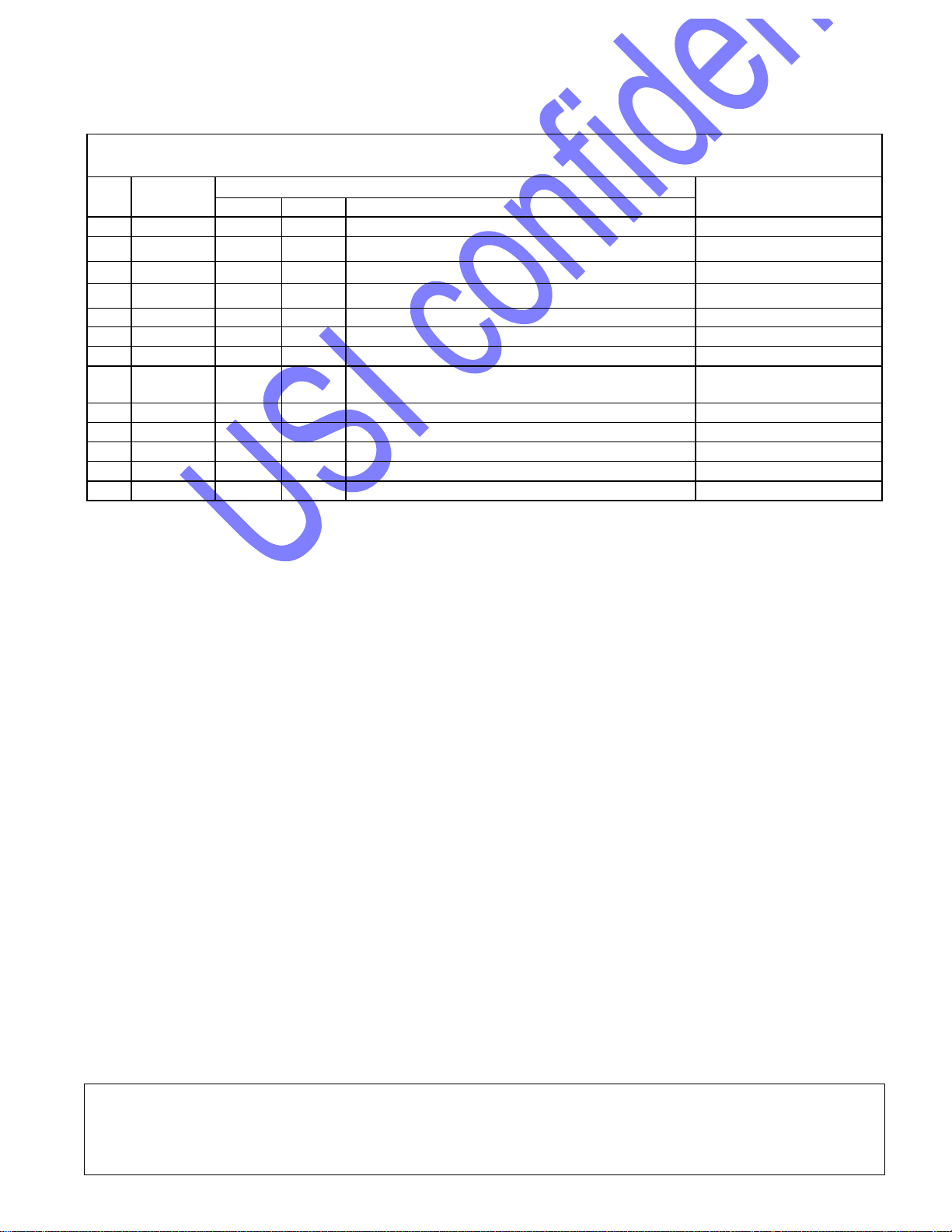
Change Sheet
Rev.
Date
Description of change
Prepared by
Page
Par
Change(s)
1.0
2017.01.13
All
All
Preliminary version for Review
Jacal Tseng/rk
1.1
2017.03.27
10
10
Update power consumption of BT
Jacal Tseng
1.2
2017.05.8
10
10
Update power consumption
Jacal Tseng/Jason
1.3
2017.08.18
35
35
Update dimension of footprint
Jacal Tseng
1.4
2017.08.21
9
9
Update Technical Specification
Jacal Tseng
1.4
2017.08.21
1
1
Add USI P/N
Jacal Tseng
1.5
2018.01.18
9
9
Update operation temperature range
Jacal Tseng
1.6
2018.05.03
Front
Page
Front
Page
New P/N to add in
Jason Tsai

802.11a/b/g/n/ac + BT Wireless LAN Module V1.6
All# rights# are# reserved# by# USI.# No# part# of# this# technical# document# can# be# reproduced# in# any# form#
without#permission#of#USI#
4#
TABLE OF CONTENTS
1! BLOCK DIAGRAM .................................................................................. 7!
2! DELIVERABLES ..................................................................................... 8!
3! REFERENCE DOCUMENTS .................................................................. 8!
4! TECHNICAL SPECIFICATION ............................................................... 9!
4.1! ABSOLUTE MAXIMUM RATING .............................................................................................. 9!
4.2! RECOMMENDABLE OPERATION CONDITION .................................................................................... 9!
4.2.1! TEMPERATURE, HUMIDITY ............................................................................................. 9!
4.2.2! VOLTAGE .............................................................................................................................. 9!
4.2.3! CURRENT CONSUMPTION ............................................................................................ 10!
4.3! WIRELESS SPECIFICATIONS ......................................................................................................... 12!
4.4! RADIO SPECIFICATIONS 802.11A/B/G/N/AC ................................................................................ 12!
4.4.1! 802.11B TRANSMIT .......................................................................................................... 12!
4.4.2! 802.11G TRANSMIT ......................................................................................................... 13!
4.4.3! 802.11A TRANSMIT .......................................................................................................... 13!
4.4.4! 2.4GHz 802.11N TRANSMIT – HT20 ............................................................................. 14!
4.4.5! 5GHz 802.11N TRANSMIT – HT20 ................................................................................ 14!
4.4.6! 802.11AC TRANSMIT – HT80 ......................................................................................... 15!
4.4.7! 802.11B RECEIVER .......................................................................................................... 15!
4.4.8! 802.11G RECEIVER ......................................................................................................... 15!
4.4.9! 802.11A RECEIVER .......................................................................................................... 16!
4.4.10! 802.11N RECEIVER ........................................................................................................ 16!
4.4.11! 802.11AC RECEIVER ..................................................................................................... 16!
4.5! RADIO SPECIFICATIONS 802.15 BLUETOOTH ........................................................................... 17!
4.6! BLUETOOTH RADIO CHARACTERISTICS ....................................................................................... 17!
4.7! REFERENCE CIRCUIT ................................................................................................................... 18!
4.8! TIMING DIAGRAM OF IN T ERFACE .................................................................................................. 19!
4.8.1! CONTROL SIGNAL TIMING DIAGRAMS ..................................................................... 19!
4.8.2! UART TIMING .................................................................................................................... 21!
4.8.3! SDIO TIMING ..................................................................................................................... 21!
4.8.4! PCM TIMING ...................................................................................................................... 24!
4.9! FREQUENCY REFERENCES ........................................................................................................... 30!
4.9.1! EXTERNAL 32.768kHz LOW-POWER OSCILLATOR ................................................ 30!
4.10! DIMENSIONS, WEIGHT AND MOUNTING ....................................................................................... 31!
4.10.1! DIMENSION & MODEL CODE ...................................................................................... 31!
5! LEGAL, REGULATORY & OTHER TECHNICAL CONSTRAINTS ..... 32!
6! PIN OUT AND PIN DESCRIPTION ....................................................... 32!

802.11a/b/g/n/ac + BT Wireless LAN Module V1.6
All# rights# are# reserved# by# USI.# No# part# of# this# technical# document# can# be# reproduced# in# any# form#
without#permission#of#USI#
5#
7! GUIDELINE TO PERFORM SMT WITH MODULE ............................... 35!
7.1! PCB FOOTPRINT RECOMMENDATION .......................................................................................... 35!
7.2! REFLOW PROFILE GUIDELINE ...................................................................................................... 36!
7.3! RECOMMENDED REFLOW PROFILE .............................................................................................. 37!
8! PACKAGE AND STORAGE CONDITION ............................................ 38!
8.1! PACKAGE ...................................................................................................................................... 38!
8.2! EMC/ESD LEVEL ........................................................................................................................ 38!
8.3! MSL LEVEL/STORAGE CONDITION (REFERENCE#ONLY) ............................................................... 39!

802.11a/b/g/n/ac + BT Wireless LAN Module V1.6
All# rights# are# reserved# by# USI.# No# part# of# this# technical# document# can# be# reproduced# in# any# form#
without#permission#of#USI#
6#
EXECUTIVE SUMMARY
The WM-BAC-BM-25 module is one of the product families in USI’s product offering, targeting for
system integration requiring the module with antenna together for verification.
The purpose of this document is defined the product specification for 802.11a/b/g/n/ac Wi-Fi with
BT4.2 SIP module WM-BAC-BM-25. All the data in this document is based on CYW43455
datasheet and other documents. The data will be updated after implementing the measurement of
the module.
This product is designated for using in embedded ap p lic ations, whic h required high integration and
high data rate wir e less conn e c t iv ity. The application such as DSC, IPCAM, Media Adapter,
Barcode scanner, mini-Printer, VoIP phone, Data storage device could be the potential application
for wireless application.
802.11a/b/g/n/ac + BT Wireless LAN Module V1.6
All# rights# are# reserved# by# USI.# No# part# of# this# technical# document# can# be# reproduced# in# any# form#
without#permission#of#USI#
7#
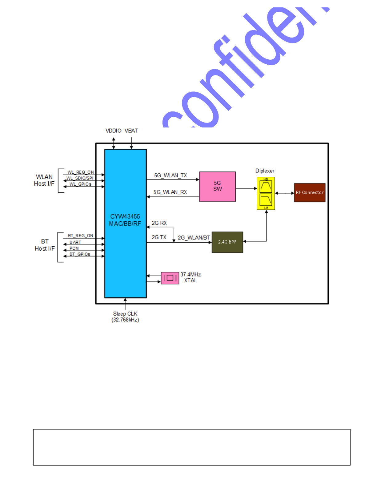
1 BLOCK DIAGRAM
The module is designed based on CYW43455 chipset solution. For the WLAN section, the host
interface is in c luded: a SDI O v3.0 interface, which can operate in 4b, or 1b mode. An independent,
high-speed UART is provided for the Bluetooth host interface.
A brief block diagram of the WM-BAC-BM-25 module is depicted as below figure.

802.11a/b/g/n/ac + BT Wireless LAN Module V1.6
All# rights# are# reserved# by# USI.# No# part# of# this# technical# document# can# be# reproduced# in# any# form#
without#permission#of#USI#
8#
2 DELIVERABLES
The following products and software will be part of the product.
WM-BAC-BM-25 Module with packaging
Evaluation kits (with SDIO/SPI/UART interface)
Software utility which supporting customer for in tegration, performance test and homologat io n.
Capable of testing, loading (firmware) and configuring (MAC, CIS) for the WM-BAC-BM-25 module.
Unit Test / Qualification report
Product Specifications.
Agency certification pre-test report base on adapter boards
3 REFERENCE DOCUMENTS
C.I.S.P.R.
Pub. 22
"Limits and methods of measurement of radio interference characteristics of
information technology equipment." International Specia l Committee on Radio
Interference (C.I.S.P.R.), T h ird E d ition, 1 99 7 .
CB Bulletin
No. 96A
"Adherence to IEC Standards: “Re qu irem e nts for IEC 950, 2nd Edition and
Amendments 1 (1991), 2(1993), 3 (1995) and 4(1996). Product Categories: Meas,
Med, Off, Tron." IEC System for Conformity Testing to Standards for Safety of
Electrical Equipment (IECEE), April 2000.
CFR 47,
Part 15-B
"Unintentional Radiators". Title 47 of th e Code of Federal Regulations, Part 15, F C C
Rules, Radio Frequency Devices, Subpart B.
CFR 47,
Part 15-C
"Intentional Radiators". Title 47 of the Code of Federal Regulations, Part 15, FC C
Rules, Subpart C. URL:
http://www.access.gpo.gov/nara/cfr/waisidx_98/47cfr15_98.html
CSA C22.2
No. 950-95
"Safety of Information Technology Equipment including Electrical Business Equipment,
Third Edition." Canadian Standards Association, 1995, including revised pages
through July 1997.
EN 60 950
"Safety of Information Tech no logy Equipment Including Electrical B us ines s
Equipment." European Committee for Electrotechnical Standardization (CENELEC),
1996, (IEC 950, Second Edition, including Amendment 1, 2, 3 and 4).
IEC 950
"Safety of Information Tech no logy Equipment Including Electrical B us ines s
Equipment." European Committee for Electrotechnical Standardization, Intentional
Electrotechnical Commission. 1991, Second Edition, including Amendments 1, 2, 3,
and 4.
IEEE 802.11
“Wireless LAN Medium Access Control (MAC) And Physical La ye r (PHY)
Specifications.” Institute of Electrical and Electronics Engineers. 2012.
802.11a/b/g/n/ac + BT Wireless LAN Module V1.6
All# rights# are# reserved# by# USI.# No# part# of# this# technical# document# can# be# reproduced# in# any# form#
without#permission#of#USI#
9#
4 TECHNICAL SPECIFICATION
4.1 ABSOLUTE MAXIMUM RATING
Symbol
Parameter
Conditions
Min
Max
Unit
VBAT
Main input supply from battery to switcher
-0.5
6.0a
V
VDDIO
DC supply voltage for digital I/O
-0.5
3.9
V
ESD
Electro-static discharge voltage
HBM
2 KV
Ts
Storage temperature
-40
85
℃
VBAT
Operating temperature
-40
85
℃
VBAT
Voltage rippleb
-2 2 %
Notes: a. The maximum continuous voltage is 5.25V. Voltages up to 6.0V for up to 10 seconds, cumulative
duration, over the lifetime of the device are allowed.
b. To achieve optimal RF performance, please keep ripple value under 20 mV as possible.
4.2 RECOMMENDABLE OPERATION CONDITION
4.2.1 TEMPERATURE, HUMIDITY
The WM-BAC-BM-25 module has to withstand the operational requirements as listed in the table
below.
Operating Temperature
-40° to 85° Celsius
Specification Temperature Range
-10° to 65° Celsius
Relative Humidity range
Max 95%
Non condensing , relative humidity
Notes: All RF characteristic in this datasheet are defined by Specification Temperature Range.
RF performance may derating under over-temperature and over-voltage range condition.
4.2.2 VOLTAGE
Power supply for the WM-BAC-BM-25 module will be provided by the host via the power pins
Symbol
Parameter
Min
Typ.
Max
Unit
VBAT
Operation Voltage
3.0 3.6
5.25
*
b
V
Specification Voltage
*
a
3.2
3.6
4.8
V
VDDIO
DC supply voltage for digital I/O
1.62
1.8
3.63
V
3.3
Notes: a. All RF characteristics in this datasheet are defined by Specification Voltage.
b. The maximum continuous voltage is 5.25V.

802.11a/b/g/n/ac + BT Wireless LAN Module V1.6
All# rights# are# reserved# by# USI.# No# part# of# this# technical# document# can# be# reproduced# in# any# form#
without#permission#of#USI#
10#
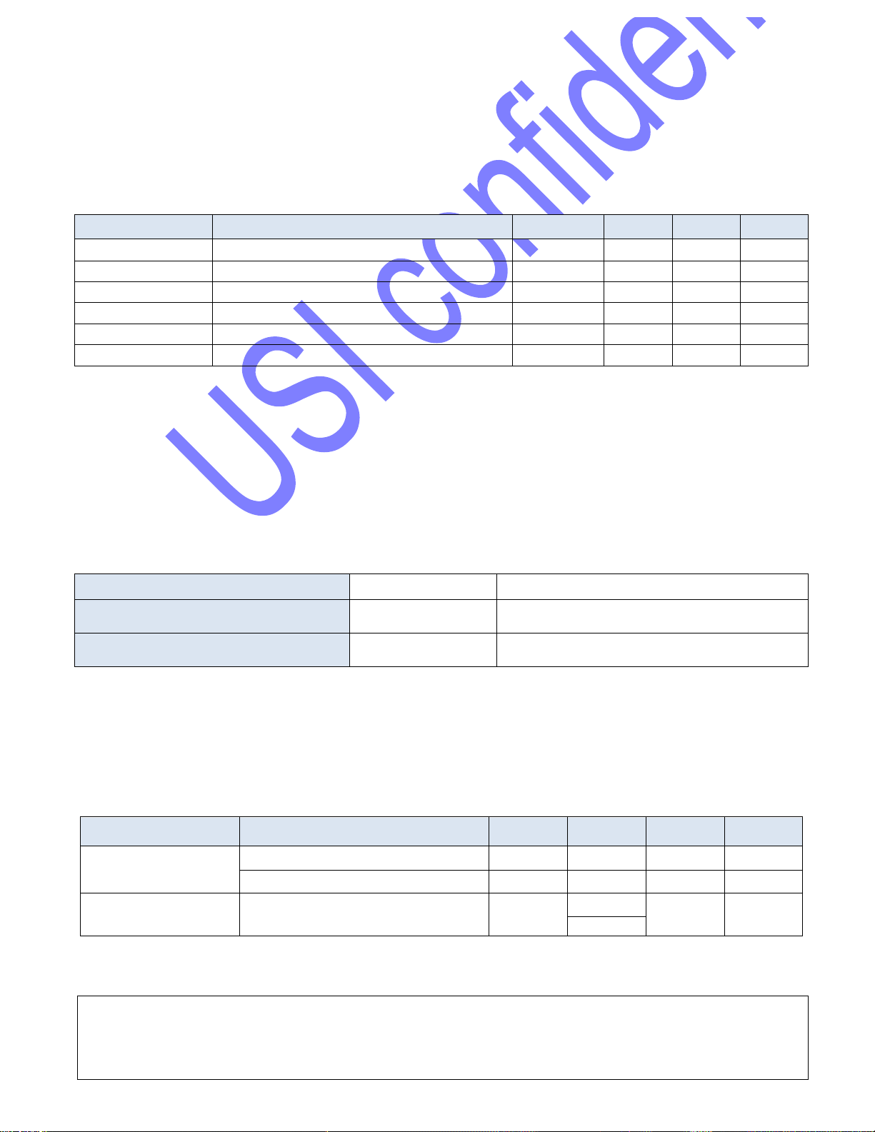
4.2.3 CURRENT CONSUMPTION
(VBAT = +3.0V to +5.25V, VDDIO = +3.3V, TA = -10C to +65°C, 50Ω nominal system impedance.
Typical values of VBAT+VDDIO shown below are at VBATT = +3.6V and TA = +25°C)
2.4GHz
Item
Condition
Typ.
Max
Unit
Tx
1Mbps
Continuous Tx @ 17 dBm
389
401
mA
11Mbps
Continuous Tx @ 17 dBm
353
378
mA
6Mbps
Continuous Tx @ 15 dBm
336
355
mA
54Mbps
Continuous Tx @ 15 dBm
273
290
mA
MCS0
(HT20)
Continuous Tx @ 15 dBm
340
353
mA
MCS7
(HT20)
Continuous Tx @ 15 dBm
272
294
mA
BT Class1
Continuous Tx @ 8 dBm
45
55
mA
BT Class2
Continuous Tx @ 0 dBm
28
33
mA
Rx
1Mbps
Rx sensitivity @ -95 dBm
76.4
84
mA
11Mbps
Rx sensitivity @ -88 dBm
77
88
mA
6Mbps
Rx sensitivity @ -89 dBm
76
85
mA
54Mbps
Rx sensitivity @ -74 dBm
77
86
mA
MCS0
(HT20)
Rx sensitivity @ -89 dBm
76.1
88
mA
MCS7
(HT20)
Rx sensitivity @-71 dBm
77
87
mA
BT
Rx sensitivity @ -85 dbm
22
30
mA
802.11a/b/g/n/ac + BT Wireless LAN Module V1.6
All# rights# are# reserved# by# USI.# No# part# of# this# technical# document# can# be# reproduced# in# any# form#
without#permission#of#USI#
11#
Operating Mode/Condition
Typ.
Max
Unit
BT Sleep Mode
6
-
uA
WIFI Sleep Mode
25
-
uA
Power off Mode
6
10
uA
Note: The Current Consumption will be updated after samples reliability test
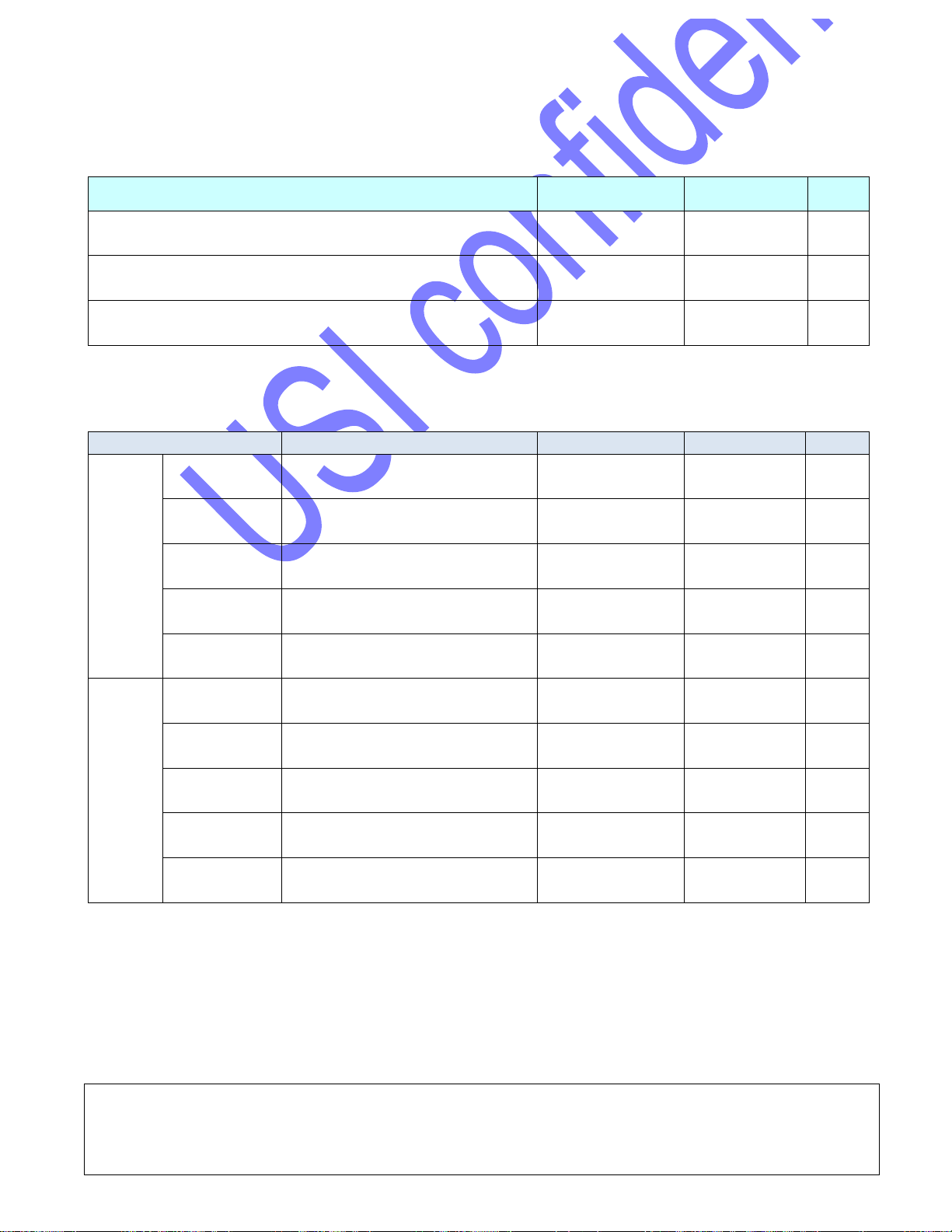
5GHz
Item
Condition
Typ.
Max
Unit
Tx
6Mbps
Continuous Tx @ 15 dBm
338
366
mA
54Mbps
Continuous Tx @ 15 dBm
274
289
mA
MCS0
(HT20)
Continuous Tx @ 15 dBm
334
357
mA
MCS7
(HT20)
Continuous Tx @ 15 dBm
267
291
mA
MCS9
(VHT80)
Continuous Tx @ 12 dBm
224
244
mA
Rx
6Mbps
Rx sensitivity @ -89 dBm
91.1
101
mA
54Mbps
Rx sensitivity @ -74 dBm
92.1
102
mA
MCS0
(HT20)
Rx sensitivity @ -89 dBm
91.1
100
mA
MCS7
(HT20)
Rx sensitivity @ -71 dBm
92.2
102
mA
MCS9
(VHT80)
Rx sensitivity @ -63 dBm
122
141
mA
Note: The Current Consumption will be updated after samples reliability test
802.11a/b/g/n/ac + BT Wireless LAN Module V1.6
All# rights# are# reserved# by# USI.# No# part# of# this# technical# document# can# be# reproduced# in# any# form#
without#permission#of#USI#
12#
4.3 WIRELESS SPECIFICATIONS
The WM-BAC-BM-25 module complies with the following features and standards;
Features
Description
WLAN Standards
IEEE 802 Part 11a/b/g/n/ac (8 0 2.1 1a/b/g/n/ac)
Bluetooth
Bluetooth
TM
4.2 compliance
Frequency Band
2.4 to 2.497GHz (1 to 14 channels )
4.9 to 5.845GHz
4.4 RADIO SPECIFICATIONS 802.11A/B/G/N/AC
The RF performance of WM-BAC-BM-25 is given as follows.
Condition: VBAT= 3.6V 、 VDDIO=3.3V at room Temperature
4.4.1 802.11B TRANSMIT
Item
Condition
Min.
Typ.*c
Max.
*d
Unit
Target Output Power Level*b
11Mbps
-
17
17.5
dBm
Target Output Power Level*b
1Mbps - 17
17.5
dBm
Transmit center frequency tolerance*a
-25 - 25
ppm
Transmit spectral mask
@+/-11MHz
- - -30*a
dBr
@+/-22MHz
- - -50*a
dBr
Notes: a. Refer to IEEE802.11 specification.
b. Output power tolerance is +/- 2dB.
c. Typical TX power
d. Max. allowed TX power
Notes: The Output Power Level will be updated after samples reliability test.
 Loading...