

Page 1
micros
®
Systems, Inc.
Workstation 4 LX
Field Service Guide
Workstation 4
and
Copyright 2004 - 2008
By MICROS Systems, Inc.
Columbia, Mary land USA
All Rights Reserved
Part Number 100016-118 (4th Edition)
Page 2

Declarations
Warranties
Trademarks
Although the best efforts are made to ensure that the information
contained in this manual is comple te and cor re ct, MICROS Systems, Inc.
makes no warranty of any kind with regard to this material, including but
not limited to the implied warranties of marketability and fitness for a
particular purpose. Information in this manual is subject to change
without notice. MICROS Systems, Inc. shall not be liable for errors
contained herein or for i ncidental or conse quential dama ges in connectio n
with the furnishing, performance, or use of this material.
MICROS is a registered trademark of MICROS Systems, Inc.
Microsoft, MS-DOS, Windows, Windows 95, and Windows CE are registered
trademarks of Microsoft Corporation in the U.S. and other countries.
AMD, the AMD logo, and combinations there of are trademarks of Advanced
Micro Devices, Inc.
General Software, the GS Logo, Embedded BIOS, CE Ready, the CE Ready
logo, and Firmbase are trademarks or registered trademarks of General
Software, Inc.
Printing History
New editions of this manual incorporate new and changed material since
the previous edition. Minor corrections and updates may be incorporated
into reprints of the current edition without changing the date or edition
number.
1st Edition: March 2004
2nd Edition: March 2005
3rd Edition: January 2007
4th Edition: January 2008
ii
Page 3

Table Of Contents
Table Of Contents
Preface
Purpose . . . . . . . . . . . . . . . . . . . . . . . . . . . . . . . . . . . . . . . . . . . . . . . . . . . . . . . .
Who Should Use This Manual?. . . . . . . . . . . . . . . . . . . . . . . . . . . . . . . . . vi
Symbols . . . . . . . . . . . . . . . . . . . . . . . . . . . . . . . . . . . . . . . . . . . . . . . . . .vii
Document Design and Production. . . . . . . . . . . . . . . . . . . . . . . . . . . . . . . iv
Daughter
Introduction to the WS4/WS4 LX FRUs
Introduction . . . . . . . . . . . . . . . . . . . . . . . . . . . . . . . . . . . . . . . . . . . . . . . . . 1-2
Base Casework - WS4 and WS4 LX. . . . . . . . . . . . . . . . . . . . . . . . . . . . . . . 1-3
System Boards and Components. . . . . . . . . . . . . . . . . . . . . . . . . . . . . . . . . . 1-5
WS4 System Boards - A Short History. . . . . . . . . . . . . . . . . . . . . . . . . . 1-5
The Workstation 4 LX System Board . . . . . . . . . . . . . . . . . . . . . . . . . . . 1-7
Workstation 4 System Board and Components. . . . . . . . . . . . . . . . . . . . . . . 1-8
Workstation 4 LX System Board and Components . . . . . . . . . . . . . . . . . . 1-10
Cables and Toroids . . . . . . . . . . . . . . . . . . . . . . . . . . . . . . . . . . . . . . . . . . . 1-12
Cable, Samsung LCD Display, REV F/G . . . . . . . . . . . . . . . . . . . . . . . 1-12
Cable, Samsung LCD Display, REV I . . . . . . . . . . . . . . . . . . . . . . . . . 1-13
Cable, Sharp LCD Display, REV F/G. . . . . . . . . . . . . . . . . . . . . . . . . . 1-13
Cable, Sharp LCD Display, REV I . . . . . . . . . . . . . . . . . . . . . . . . . . . . 1-14
Cable Inverter, F/G BD, WS4 . . . . . . . . . . . . . . . . . . . . . . . . . . . . . . . . 1-14
Cable, Inverter to REV I BD, WS4 or WS4 LX . . . . . . . . . . . . . . . . . . 1-15
Touchscreen Extension Cable . . . . . . . . . . . . . . . . . . . . . . . . . . . . . . . . 1-15
Cable Kit, Power In - Power Out, AC Conn . . . . . . . . . . . . . . . . . . . . 1-16
Toroid Kit, Display, MSR and AC Power . . . . . . . . . . . . . . . . . . . . . . 1-16
AC Power Input Cable . . . . . . . . . . . . . . . . . . . . . . . . . . . . . . . . . . . . . 1-17
Workstation 4 and 4 LX - LCD/Touchscreen/Mag Stripe Reader . . . . . . . 1-18
Samsung LCD Related . . . . . . . . . . . . . . . . . . . . . . . . . . . . . . . . . . . . . 1-18
Sharp LCD Related . . . . . . . . . . . . . . . . . . . . . . . . . . . . . . . . . . . . . . . . 1-20
Touchscreen and Front Cover Plastic . . . . . . . . . . . . . . . . . . . . . . . . . . 1-21
Top Cover - Mag Stripe Reader Assembly and Cover . . . . . . . . . . . . . 1-22
LCD Customer Display . . . . . . . . . . . . . . . . . . . . . . . . . . . . . . . . . . . . . . . 1-23
LCD Interface Board . . . . . . . . . . . . . . . . . . . . . . . . . . . . . . . . . . . . . . . . . 1-23
LCD Module, Optrex . . . . . . . . . . . . . . . . . . . . . . . . . . . . . . . . . . . . . . 1-23
Cable, LCD Pole and Rear Display Head . . . . . . . . . . . . . . . . . . . . . . 1-24
Cable Extension, LCD Pole Display . . . . . . . . . . . . . . . . . . . . . . . . . . 1-24
Kit, Front/Rear Cover, /w Lens, Screws, Pole Mount Hinge . . . . . . . . 1-25
Kit, Front/Rear Cover, /w Lens, Screws, Rear Mount Hinge . . . . . . . . 1-25
iii
Page 4

Table of Contents
Workstation 4 Technical Overview
Workstation 4 System Block Diagrams . . . . . . . . . . . . . . . . . . . . . . . . . . . . 2-2
SC3200 GX1 Processor, Video Processor, Core Logic and Super IO . . . . 2-5
GX1 Processor . . . . . . . . . . . . . . . . . . . . . . . . . . . . . . . . . . . . . . . . . . . . 2-6
Video Processor . . . . . . . . . . . . . . . . . . . . . . . . . . . . . . . . . . . . . . . . . . . 2-6
Core Logic . . . . . . . . . . . . . . . . . . . . . . . . . . . . . . . . . . . . . . . . . . . . . . . 2-7
PCI and Sub-ISA Bus Interface . . . . . . . . . . . . . . . . . . . . . . . . . . . . . . . . . . 2-8
Sub-ISA Bus Interface . . . . . . . . . . . . . . . . . . . . . . . . . . . . . . . . . . . . . . 2-9
Boot Loader . . . . . . . . . . . . . . . . . . . . . . . . . . . . . . . . . . . . . . . . . . . . . . 2-9
Disk On Chip (DOC) . . . . . . . . . . . . . . . . . . . . . . . . . . . . . . . . . . . . . . . 2-9
SC3200 Super I/O. . . . . . . . . . . . . . . . . . . . . . . . . . . . . . . . . . . . . . . . . . . . 2-11
PC87360 Super IO . . . . . . . . . . . . . . . . . . . . . . . . . . . . . . . . . . . . . . . . . . . 2-12
General Purpose IO . . . . . . . . . . . . . . . . . . . . . . . . . . . . . . . . . . . . . . . 2-13
Parallel Port. . . . . . . . . . . . . . . . . . . . . . . . . . . . . . . . . . . . . . . . . . . . . . 2-13
Operator LED Control . . . . . . . . . . . . . . . . . . . . . . . . . . . . . . . . . . . . . 2-14
Serial Interface . . . . . . . . . . . . . . . . . . . . . . . . . . . . . . . . . . . . . . . . . . . 2-15
Keyboard and Mouse Controller . . . . . . . . . . . . . . . . . . . . . . . . . . . . . 2-15
ACCESS.bus Interface . . . . . . . . . . . . . . . . . . . . . . . . . . . . . . . . . . . . . 2-16
Low Pin Count (LPC) Interface . . . . . . . . . . . . . . . . . . . . . . . . . . . . . . 2-16
TFT LCD Interface. . . . . . . . . . . . . . . . . . . . . . . . . . . . . . . . . . . . . . . . . . . 2-17
Touchscreen Interface . . . . . . . . . . . . . . . . . . . . . . . . . . . . . . . . . . . . . . . . 2-20
Optional PCMCIA Daughter Card . . . . . . . . . . . . . . . . . . . . . . . . . . . . . . 2-21
Optional Mini-PCI Daughter Card . . . . . . . . . . . . . . . . . . . . . . . . . . . . . . 2-22
Complex Programmable Logic Device (CPLD). . . . . . . . . . . . . . . . . . . . . 2-23
CPU Interface and Register Control . . . . . . . . . . . . . . . . . . . . . . . . . . 2-23
Power Button (AB28 System Boards . . . . . . . . . . . . . . . . . . . . . . . . . . 2-25
Power Button (ABRD36 System Board) . . . . . . . . . . . . . . . . . . . . . . . 2-26
Reset Circuit . . . . . . . . . . . . . . . . . . . . . . . . . . . . . . . . . . . . . . . . . . . . 2-28
Wake On LAN Power Management Event . . . . . . . . . . . . . . . . . . . . . 2-29
LCD Backlight Control. . . . . . . . . . . . . . . . . . . . . . . . . . . . . . . . . . . . . 2-30
Cash Drawer Interface . . . . . . . . . . . . . . . . . . . . . . . . . . . . . . . . . . . . . 2-31
System Board Hardware Revision . . . . . . . . . . . . . . . . . . . . . . . . . . . . 2-32
DP83815 10/100 Mbps PCI Ethernet Controller . . . . . . . . . . . . . . . . . . . . 2-33
EEPROM . . . . . . . . . . . . . . . . . . . . . . . . . . . . . . . . . . . . . . . . . . . . . . . . . . 2-34
RS422 Port A and RS422 B . . . . . . . . . . . . . . . . . . . . . . . . . . . . . . . . . . . . 2-35
RS422 Port A . . . . . . . . . . . . . . . . . . . . . . . . . . . . . . . . . . . . . . . . . . . . 2-35
RS422 Port B . . . . . . . . . . . . . . . . . . . . . . . . . . . . . . . . . . . . . . . . . . . . 2-36
Customer Display/Mag Card Reader Port (COM3) . . . . . . . . . . . . . . . . . . 2-38
COM3 Configuration - AB28-F and AB28-G . . . . . . . . . . . . . . . . . . . 2-38
COM3 Configuration - AB28-I or ABRD36-B . . . . . . . . . . . . . . . . . . 2-40
Multiplexer Operation . . . . . . . . . . . . . . . . . . . . . . . . . . . . . . . . . . . . . 2-42
Optional LCD Customer Display . . . . . . . . . . . . . . . . . . . . . . . . . . . . . . . 2-44
Casework . . . . . . . . . . . . . . . . . . . . . . . . . . . . . . . . . . . . . . . . . . . . . . . 2-45
Interface Board and LCD . . . . . . . . . . . . . . . . . . . . . . . . . . . . . . . . . . . 2-45
iv
Page 5

Table Of Contents
Interface Board Description . . . . . . . . . . . . . . . . . . . . . . . . . . . . . . . . . 2-46
Cables . . . . . . . . . . . . . . . . . . . . . . . . . . . . . . . . . . . . . . . . . . . . . . . . . . 2-47
Hardware Compatibility - System Board Hardware Revision . . . . . . . 2-47
Enabling the LCD Customer Display - WS4 . . . . . . . . . . . . . . . . . . . . 2-47
Enabling the LCD Customer Display - WS4 LX . . . . . . . . . . . . . . . . . 2-47
Workstation 4 Troubleshooting
Introduction . . . . . . . . . . . . . . . . . . . . . . . . . . . . . . . . . . . . . . . . . . . . . . . . . . 3-2
Software Utilities . . . . . . . . . . . . . . . . . . . . . . . . . . . . . . . . . . . . . . . . . . 3-2
Operational Troubleshooting . . . . . . . . . . . . . . . . . . . . . . . . . . . . . . . . . . . . 3-4
Original Workstation 4 Boot Sequence . . . . . . . . . . . . . . . . . . . . . . . . . 3-4
Testing the Power Supply and System Board Voltage Regulators . . . . . . . 3-8
POST Errors . . . . . . . . . . . . . . . . . . . . . . . . . . . . . . . . . . . . . . . . . . . . . . . . 3-11
LCD Display Related . . . . . . . . . . . . . . . . . . . . . . . . . . . . . . . . . . . . . . . . . 3-14
Touchscreen Related . . . . . . . . . . . . . . . . . . . . . . . . . . . . . . . . . . . . . . . . . . 3-16
Local Area Network (LAN) Related . . . . . . . . . . . . . . . . . . . . . . . . . . . . . . 3-18
Mechanical Related . . . . . . . . . . . . . . . . . . . . . . . . . . . . . . . . . . . . . . . . . . . 3-21
Peripheral Related . . . . . . . . . . . . . . . . . . . . . . . . . . . . . . . . . . . . . . . . . . . . 3-22
IDN Port Problems . . . . . . . . . . . . . . . . . . . . . . . . . . . . . . . . . . . . . . . . 3-22
RS232 Peripheral Device Does Not Function. . . . . . . . . . . . . . . . . . . . 3-22
USB Peripherals Do Not Function . . . . . . . . . . . . . . . . . . . . . . . . . . . . 3-23
VFD Pole Display . . . . . . . . . . . . . . . . . . . . . . . . . . . . . . . . . . . . . . . . . 3-23
LCD Customer Display. . . . . . . . . . . . . . . . . . . . . . . . . . . . . . . . . . . . . 3-24
Workstation Recovery Procedures . . . . . . . . . . . . . . . . . . . . . . . . . . . . . . . 3-26
Formatting the CF Card. . . . . . . . . . . . . . . . . . . . . . . . . . . . . . . . . . . . . 3-26
Using the CAL. . . . . . . . . . . . . . . . . . . . . . . . . . . . . . . . . . . . . . . . . . . . 3-27
Workstation 4 Diagnostics Utility. . . . . . . . . . . . . . . . . . . . . . . . . . . . . . . . 3-28
System Information Screen - Hardware Components. . . . . . . . . . . . . . 3-29
System Information Screen - Platform Software Components . . . . . . . 3-31
Other Platform Files and Folders . . . . . . . . . . . . . . . . . . . . . . . . . . . . . 3-34
v
Page 6

Table of Contents
Workstation 4 LX Technical Overview
Workstation 4 LX System Board Block Diagram . . . . . . . . . . . . . . . . . . . . 4-2
LX800 Processor and TFT Controller . . . . . . . . . . . . . . . . . . . . . . . . . . . . . 4-3
Processor Core . . . . . . . . . . . . . . . . . . . . . . . . . . . . . . . . . . . . . . . . . . . . 4-4
GeodeLink Interface Units . . . . . . . . . . . . . . . . . . . . . . . . . . . . . . . . . . . 4-4
GeodeLink Memory Controller . . . . . . . . . . . . . . . . . . . . . . . . . . . . . . . 4-4
GeodeLink Control Processor. . . . . . . . . . . . . . . . . . . . . . . . . . . . . . . . . 4-5
GeodeLink PCI Bridge . . . . . . . . . . . . . . . . . . . . . . . . . . . . . . . . . . . . . . 4-5
GeodeLink General Description. . . . . . . . . . . . . . . . . . . . . . . . . . . . . . . 4-6
CS5536 Companion Device . . . . . . . . . . . . . . . . . . . . . . . . . . . . . . . . . . . . . 4-7
System Management Bus (SMB) Controller . . . . . . . . . . . . . . . . . . . . . 4-7
Serial Interface . . . . . . . . . . . . . . . . . . . . . . . . . . . . . . . . . . . . . . . . . . . . 4-7
Real Time Clock (RTC) and CMOS RAM . . . . . . . . . . . . . . . . . . . . . . 4-7
ATA Interface. . . . . . . . . . . . . . . . . . . . . . . . . . . . . . . . . . . . . . . . . . . . . 4-7
USB Interface . . . . . . . . . . . . . . . . . . . . . . . . . . . . . . . . . . . . . . . . . . . . . 4-8
LPC Interface . . . . . . . . . . . . . . . . . . . . . . . . . . . . . . . . . . . . . . . . . . . . . 4-8
Audio Codec 97 Controller. . . . . . . . . . . . . . . . . . . . . . . . . . . . . . . . . . . 4-8
Power Management . . . . . . . . . . . . . . . . . . . . . . . . . . . . . . . . . . . . . . . . 4-8
IDE Interface (ABRD86 - Sheet 18). . . . . . . . . . . . . . . . . . . . . . . . . . . . 4-9
W83627HF Super IO . . . . . . . . . . . . . . . . . . . . . . . . . . . . . . . . . . . . . . . . . 4-10
Low Pin Count Interface. . . . . . . . . . . . . . . . . . . . . . . . . . . . . . . . . . . . 4-10
Serial Interface . . . . . . . . . . . . . . . . . . . . . . . . . . . . . . . . . . . . . . . . . . . 4-10
RS422 Port A and B Control Signals . . . . . . . . . . . . . . . . . . . . . . . . . . 4-11
COM3 Mux Control Signals. . . . . . . . . . . . . . . . . . . . . . . . . . . . . . . . . 4-11
Hardware Monitor. . . . . . . . . . . . . . . . . . . . . . . . . . . . . . . . . . . . . . . . . 4-11
Cash Drawer Control . . . . . . . . . . . . . . . . . . . . . . . . . . . . . . . . . . . . . . 4-11
System Board Hardware Revision . . . . . . . . . . . . . . . . . . . . . . . . . . . . 4-11
TFT LCD and Backlight Interface . . . . . . . . . . . . . . . . . . . . . . . . . . . . . . . 4-12
The Graphics Processor (GP) . . . . . . . . . . . . . . . . . . . . . . . . . . . . . . . 4-12
The Display Controller (DC) . . . . . . . . . . . . . . . . . . . . . . . . . . . . . . . . 4-13
Video Processor (VP) . . . . . . . . . . . . . . . . . . . . . . . . . . . . . . . . . . . . . 4-13
LCD Interface . . . . . . . . . . . . . . . . . . . . . . . . . . . . . . . . . . . . . . . . . . . 4-14
Backlight Interface . . . . . . . . . . . . . . . . . . . . . . . . . . . . . . . . . . . . . . . . 4-15
USB Interface . . . . . . . . . . . . . . . . . . . . . . . . . . . . . . . . . . . . . . . . . . . . . . 4-15
Companion Device . . . . . . . . . . . . . . . . . . . . . . . . . . . . . . . . . . . . . . . 4-16
USB Flash Drive Power Controller . . . . . . . . . . . . . . . . . . . . . . . . . . . 4-16
USB Hub . . . . . . . . . . . . . . . . . . . . . . . . . . . . . . . . . . . . . . . . . . . . . . . 4-16
Touchscreen Interface . . . . . . . . . . . . . . . . . . . . . . . . . . . . . . . . . . . . . . . . 4-17
Point Of Sale Interfaces . . . . . . . . . . . . . . . . . . . . . . . . . . . . . . . . . . . . . . . 4-18
Customer Display/Mag Card Reader Port . . . . . . . . . . . . . . . . . . . . . . 4-18
Pole/Rear Customer Display . . . . . . . . . . . . . . . . . . . . . . . . . . . . . . . . 4-20
Rear LCD Customer Display Firmware Programming . . . . . . . . . . . . 4-20
RS422-A and RS422-B . . . . . . . . . . . . . . . . . . . . . . . . . . . . . . . . . . . . 4-21
Cash Drawer Interface . . . . . . . . . . . . . . . . . . . . . . . . . . . . . . . . . . . . . 4-23
vi
Page 7

Table Of Contents
Cash Drawer Closed Logic . . . . . . . . . . . . . . . . . . . . . . . . . . . . . . . . . . 4-23
System Board Hardware Revision . . . . . . . . . . . . . . . . . . . . . . . . . . . . 4-24
RTL8110SC 10/100/1000Mbps PCI Ethernet Controller . . . . . . . . . . . . . 4-25
PCI Bus Interface . . . . . . . . . . . . . . . . . . . . . . . . . . . . . . . . . . . . . . . . . 4-25
Link, Speed and Activity LED Control. . . . . . . . . . . . . . . . . . . . . . . . . 4-25
EEPROM Interface . . . . . . . . . . . . . . . . . . . . . . . . . . . . . . . . . . . . . . . . 4-25
System Board Power Distribution . . . . . . . . . . . . . . . . . . . . . . . . . . . . . . . 4-26
Standby Power Domain . . . . . . . . . . . . . . . . . . . . . . . . . . . . . . . . . . . . 4-27
Working Power Domain . . . . . . . . . . . . . . . . . . . . . . . . . . . . . . . . . . . . 4-27
Workstation 4 LX Troubleshooting
Introduction . . . . . . . . . . . . . . . . . . . . . . . . . . . . . . . . . . . . . . . . . . . . . . . . . 5-2
Operational Troubleshooting . . . . . . . . . . . . . . . . . . . . . . . . . . . . . . . . . . . . 5-4
Workstation 4 LX Boot Sequence . . . . . . . . . . . . . . . . . . . . . . . . . . . . . 5-4
Pre-boot Firmware Applications - Background . . . . . . . . . . . . . . . . . . . 5-7
Platform Updates - Background . . . . . . . . . . . . . . . . . . . . . . . . . . . . . . . 5-8
Testing the WS4 LX Power Supply and System Board Voltages . . . . . . . . 5-9
Standby Voltage Checks . . . . . . . . . . . . . . . . . . . . . . . . . . . . . . . . . . . . . . . . 5-9
Working Voltage Checks . . . . . . . . . . . . . . . . . . . . . . . . . . . . . . . . . . . . . . 5-10
Power On Self Test (POST) Errors . . . . . . . . . . . . . . . . . . . . . . . . . . . . . . 5-11
LCD Display Related . . . . . . . . . . . . . . . . . . . . . . . . . . . . . . . . . . . . . . . . . 5-13
Touchscreen Related . . . . . . . . . . . . . . . . . . . . . . . . . . . . . . . . . . . . . . . . . . 5-15
Local Area Network Related . . . . . . . . . . . . . . . . . . . . . . . . . . . . . . . . . . . 5-16
Mechanical Related . . . . . . . . . . . . . . . . . . . . . . . . . . . . . . . . . . . . . . . . . . 5-18
Peripheral Related . . . . . . . . . . . . . . . . . . . . . . . . . . . . . . . . . . . . . . . . . . . 5-19
Workstation 4 LX Diagnostics Utility . . . . . . . . . . . . . . . . . . . . . . . . . . . . 5-22
System Information Screen - Hardware Components . . . . . . . . . . . . . . . . 5-23
System Information Screen - Platform Files . . . . . . . . . . . . . . . . . . . . . . . 5-25
Workstation Recovery and Platform Update Procedures . . . . . . . . . . . . . . 5-29
Wiping the Compact Flash Card . . . . . . . . . . . . . . . . . . . . . . . . . . . . . 5-29
Platform Update . . . . . . . . . . . . . . . . . . . . . . . . . . . . . . . . . . . . . . . . . . 5-30
Using Windows CE Factory Restore . . . . . . . . . . . . . . . . . . . . . . . . . . 5-30
Factory Restore Procedure . . . . . . . . . . . . . . . . . . . . . . . . . . . . . . . . . . 5-32
vii
Page 8

Table of Contents
Remove and Replace the WS4 and WS4 LX FRUs
Introduction . . . . . . . . . . . . . . . . . . . . . . . . . . . . . . . . . . . . . . . . . . . . . . . . . 6-2
Tools Required . . . . . . . . . . . . . . . . . . . . . . . . . . . . . . . . . . . . . . . . . . . . 6-2
General Precautions for Working Inside the Workstation . . . . . . . . . . . 6-2
ESD Precautions . . . . . . . . . . . . . . . . . . . . . . . . . . . . . . . . . . . . . . . . . . 6-2
Environmental Notices . . . . . . . . . . . . . . . . . . . . . . . . . . . . . . . . . . . . . 6-3
Removing the Top Cover . . . . . . . . . . . . . . . . . . . . . . . . . . . . . . . . . . . . . . . 6-4
Removing the RF Shield . . . . . . . . . . . . . . . . . . . . . . . . . . . . . . . . . . . . . . . 6-8
Remove and Replace the Power Supply . . . . . . . . . . . . . . . . . . . . . . . . . . . 6-9
Remove and Replace the Workstation 4 System Board . . . . . . . . . . . . . . 6-11
Remove and Replace the Workstation 4 LX System Board. . . . . . . . . . . . 6-15
Remove and Replace the LCD panel . . . . . . . . . . . . . . . . . . . . . . . . . . . . . 6-19
Remove and Replace the Touchscreen . . . . . . . . . . . . . . . . . . . . . . . . . . . . 6-23
Remove and Replace the Magnetic Stripe Reader . . . . . . . . . . . . . . . . . . . 6-25
Reassembling the RF Shield. . . . . . . . . . . . . . . . . . . . . . . . . . . . . . . . . . . . 6-26
LCD Customer Display . . . . . . . . . . . . . . . . . . . . . . . . . . . . . . . . . . . . . . . 6-30
Connector and Cable Diagrams
IO Panel Connectors . . . . . . . . . . . . . . . . . . . . . . . . . . . . . . . . . . . . . . . . . . A-2
RS422-A (COM4) and RS422-B (COM5). . . . . . . . . . . . . . . . . . . . . . . A-2
10/100 Ethernet Connector. . . . . . . . . . . . . . . . . . . . . . . . . . . . . . . . . . . A-4
RS232 Connector . . . . . . . . . . . . . . . . . . . . . . . . . . . . . . . . . . . . . . . . . . A-4
Cash Drawer 1 and 2 Connectors . . . . . . . . . . . . . . . . . . . . . . . . . . . . . . A-5
PS2 Mouse/Keyboard Connectors (WS4 Only) . . . . . . . . . . . . . . . . . . . A-5
Pole Customer Display Connector . . . . . . . . . . . . . . . . . . . . . . . . . . . . . A-6
System Board Connectors . . . . . . . . . . . . . . . . . . . . . . . . . . . . . . . . . . . . . . A-7
Magnetic Stripe Interface . . . . . . . . . . . . . . . . . . . . . . . . . . . . . . . . . . . . A-7
USB Flash Drive Connector . . . . . . . . . . . . . . . . . . . . . . . . . . . . . . . . . A-7
LCD Customer Display Cables . . . . . . . . . . . . . . . . . . . . . . . . . . . . . . . . . . A-8
System Board Integrated Cable . . . . . . . . . . . . . . . . . . . . . . . . . . . . . . . A-8
LCD Customer Display Assembly Interface Cable . . . . . . . . . . . . . . . . A-8
Pole LCD Customer Display Cable . . . . . . . . . . . . . . . . . . . . . . . . . . . . A-9
Hook-up Cables . . . . . . . . . . . . . . . . . . . . . . . . . . . . . . . . . . . . . . . . . . . . . . A-8
RS232 from the RS422-A and RS422-B Ports . . . . . . . . . . . . . . . . . . . A-8
Ethernet. . . . . . . . . . . . . . . . . . . . . . . . . . . . . . . . . . . . . . . . . . . . . . . . . A-9
8-Pin to 6-Pin Hook-up RS422 Cable (300319-001) . . . . . . . . . . . . . . A-11
Cash Drawer Extension Cable . . . . . . . . . . . . . . . . . . . . . . . . . . . . . . . A-12
IDN(+) . . . . . . . . . . . . . . . . . . . . . . . . . . . . . . . . . . . . . . . . . . . . . . . A-2
LCC(-). . . . . . . . . . . . . . . . . . . . . . . . . . . . . . . . . . . . . . . . . . . . . . . . A-3
RS232 . . . . . . . . . . . . . . . . . . . . . . . . . . . . . . . . . . . . . . . . . . . . . . . . A-3
viii
Page 9

Preface
In this preface, you’ll find information about this manual. Refer to the preface if
you have questions about the organization, conventions, or contents of this
manual.
In this section
Why Read This Manual?..........................................................................ix
How This Manual Is Organized...............................................................xi
Notation Conventions..............................................................................xii
Workstation 4 and 4 LX Field Service Guide ix
Page 10

Preface
Why Read This Manual?
Why Read This Manual?
Purpose
This hardware-only guide is intended for those who will be troubleshooting and
repairing the MICROS Workstation 4 and 4 LX.
Who Should Use This Manual?
This manual is intende d for qua lifi ed serv ice per son nel who hav e experi ence wit h
the configuration and troubleshooting of MICROS point of sale terminals. The
ability to read schematics and a working knowledge of microprocessor based
systems and related test equipment is required.
The circuit and detailed start-up descriptions contained in this manual are
intended to give the techn ician a working knowl edge of the hardwa re to be used as
an aid in the troubleshooting and repair of the equipment.
Bibliography
Workstation 4:
AMD Geode
AMD Geode
DiskOnChip Millennium Plus Data Sheet Rev. 1.7
National Semiconductor Corporation PC87360 Super IO Datasheet
National Semiconductor Corporation DP83815 Ethernet Controller Datasheet
Workstation 4 LX:
AMD Geode
AMD Geode
Realtec RTL8110SC Integrated Gigabit Ethernet Controller Data Sheet
SMSC Integrated USB 2.0 Compatible Hub Datasheet Revision 1.8
Winbond W83627HF/F Super IO Datasheet Version 2.0
™
SC3200 Processor Data Book - November 2004
™
SC3200 Processor Specification Update
™
LX Processor Databook - October 2005
™
CS5536 Companion Device Databook
x Workstation 4 and 4 LX Field Service Guide
Page 11

How This Manual is Organized
The fourth edition of this field service guide incorporates the Workstation 4 LX
System Board Field Replacement Units (FRUs), technical descriptions, and test
procedures.
Chapter 1 combines the Workstation 4 and Workstation 4 LX spare Field
Replacement Units (FRUs). The FRUs are grouped into individual listings for
each system board. FRUs available for the optional LCD Customer Display are
included as well.
Chapter 2 provides technical descriptions of the original Workstation 4 System
Boards AB28 and ABRD36 with emphasis on the IDN and Customer Display/
Mag Stripe Reader interfaces, along with info on the TFT LCD interface, Super
IO, and voltage control.
Chapter 3 covers WS4 troubles hooting. The Cha pter star ts of f with a deta iled star t
up description, provides voltage test points for the internal power supply and
system board voltage regulators. Much of the troubleshooting information
contained in thi s chap ter is compiled from the experi enc e of the technicians at the
MICROS Board Repair Center.
Preface
How This Manual is Organized
Chapter 4 provides technical descriptions of the Workstation 4 LX System Board
ABRD86, with emphasis on the IDN and Customer Display/Mag Stripe Reader
interfaces, along with info on the TFT LCD interface, Super IO, and on-board
voltage regulators.
Chapter 5 covers WS4 LX Troubleshooting. The Workstation 4 LX is a new
system board that requires a new start up description and test procedure. Voltage
test points for the i ntern al power supp ly and sy stem boar d volt age regu lator s have
been updated to accommodate this update system board.
Chapter 6 includes the FRU remove/replace procedures with separate sections for
for each System Board.
Appendix A includes pin-out diagrams for all WS4 and WS5 LX connectors and
related hook-up cables.
Workstation 4 and 4 LX Field Service Guide xi
Page 12

Preface
Notation Conventions
Notation Conventions
Symbols
NOTE
This symbol brings special attention to a related item.
WARNING
This symbol indicates that specific handling instructions or
procedures are required to prevent damage to the hardware or
loss of data.
SHOCK HAZARD
This symbol calls attention to a potential hazard that requires
correct procedures in order to avoid personal injury.
STATIC SENSITIVE DEVICES
This symbol indicates that specific ESD handling procedures
are required.
Document Design and Production
Desktop Publishing: Adobe FrameMaker 6.0.
Images: Nikon CoolPix 990 or Canon PowerShot A80
Line Drawings: Corel Draw! 7.0.
Image Processing: Paint Shop Pro 8.0 - Corel Draw! 7.0.
xii Workstation 4 and 4 LX Field Service Guide
Page 13

Chapter 1
Introduction to the WS4/WS4 LX
FRUs
This section introduces the Workstation 4, Workstation 4 LX, and LCD
Customer Display FRUs. With the addition of the Workstation 4 LX, a new
section on how to distinguish each system board has been added.
In this chapter
Introduction...................................................................................................1-2
Base Casework - WS4 and WS4LX............................................................ 1-3
System Boards and Components................................................................. 1-5
Workstation 4 System Board and Components ........................................... 1-8
Workstation 4 LX System Board and Components................................... 1-10
Cables and Toroids..................................................................................... 1-12
Workstation 4 and 4 LX - LCD/Touchscreen/Mag Stripe Reader............. 1-18
LCD Customer Display ............................................................................. 1-23
Workstation 4 and 4 LX Field Service Guide 1-1
Page 14

Introduction to the WS4/WS4 LX FRUs
Introduction
Introduction
The Workstation 4 has been a very successful MICROS POS terminal - in fact, the
greatest selling unit in company history. It is now over four years old with over
172,000 units in the field. PMA 07-892 announces the WS4 end-of-life in July 2007,
with hardware support available through 2012.
This edition of th e Fiel d S ervic e Guide intr oduc es th e Workstation 4 LX system board
and related FRUs. All other components including casework, LCD, power supply,
touchscreen, and mag stripe reader are common to both workstations.
• Base Casework and Sheet Metal Components - WS4 and WS4 LX
This section contains base plastics, rear door and hinge, sheet metal components,
rubber feet, hardware and miscellaneous plastic. There are two bases available,
with usage is determined by the System Board Revision.
• System Boards, Components and Power Supply
This section begins wit h a brief hi story of t he Workstati on 4 system boar d through
the WS4 LX. To keep confusion to a minimum, each system board is referred to
by a model number designation.
• Workstation 4 System Board and Components
This section includes the original Workstation 4 System Board and major
components including a bare sys tem board, Power Supply, CF Daughter Card,
Boot Loader, Disk On Chip, DIMM, and CF card.
• WS4 LX System Board and Components
This section includes the WS4 LX System Board System Board, Power
Supply and major components including the bare system board, CF Daughter
Card, BIOS Chip, USB Flash Drive, and CF card.
• Cables and Toroids
This section include s all WS4 and WS4 LX repla cement cables and t oroid kit. The
WS4 LX system board retains compatibility with all cables used on the most
recent WS4 units.
• Top Cover - LCD, Touchscreen, and Mag Stripe Reader
This section includes top cover components such as the LCD panel, touchscreen,
and mag stripe reader. The Sharp LCD Panel recently changed from the
LQ121S1LG41 to the LQ121S1LG61, requiring an update to the INF file that
controls backlight bri ght ne ss levels. Units with the LG61 LCD ship wit h GR 2.3a
platform software.
• LCD Customer Display - WS4, WS4 LX, and WS5
Includes all replacement components for the Rear or Pole LCD based customer
display. This display may be found on the WS4, WS4 LX and the WS5.
1-2 Workstation 4 and 4 LX Field Service Guide
Page 15
Base Casework - WS4 and WS4LX
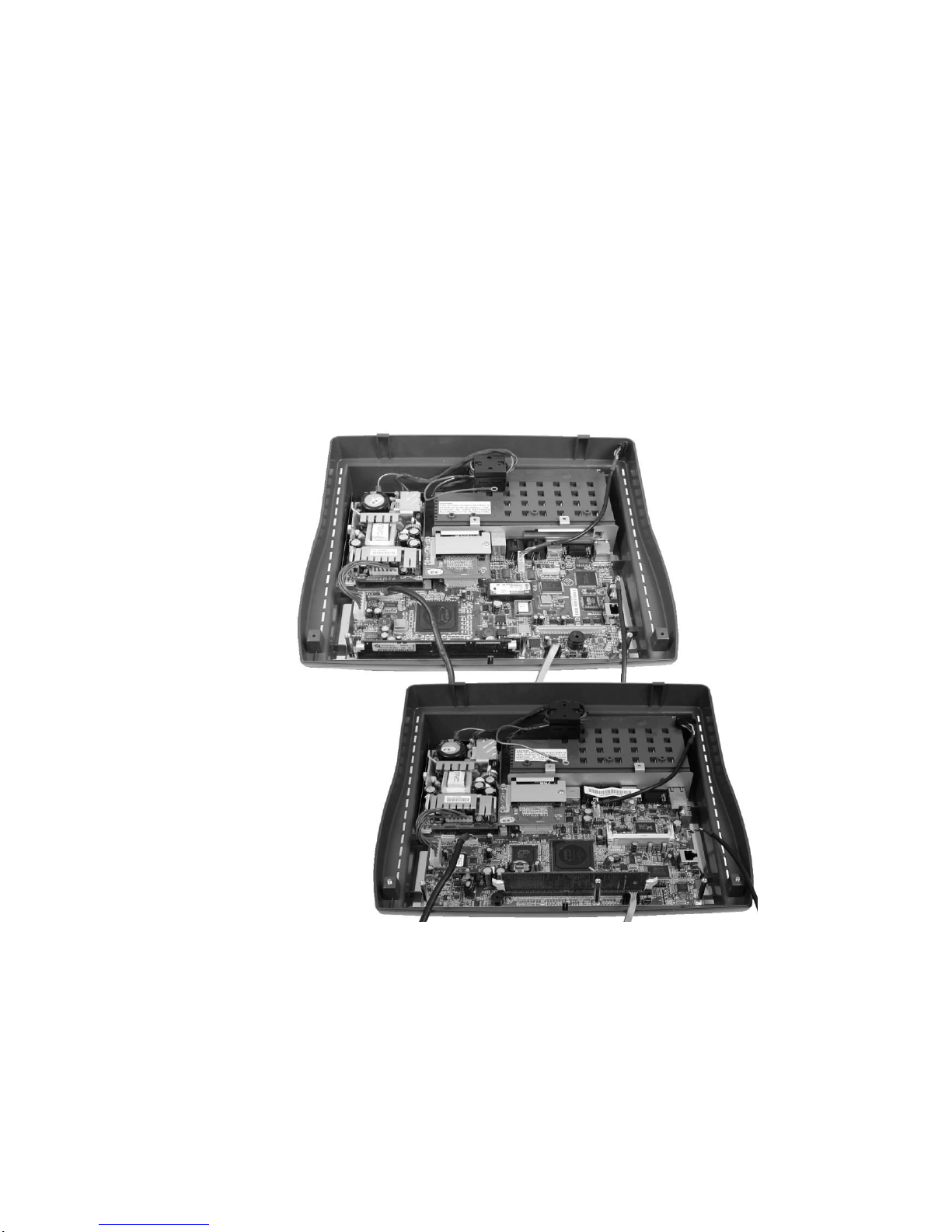
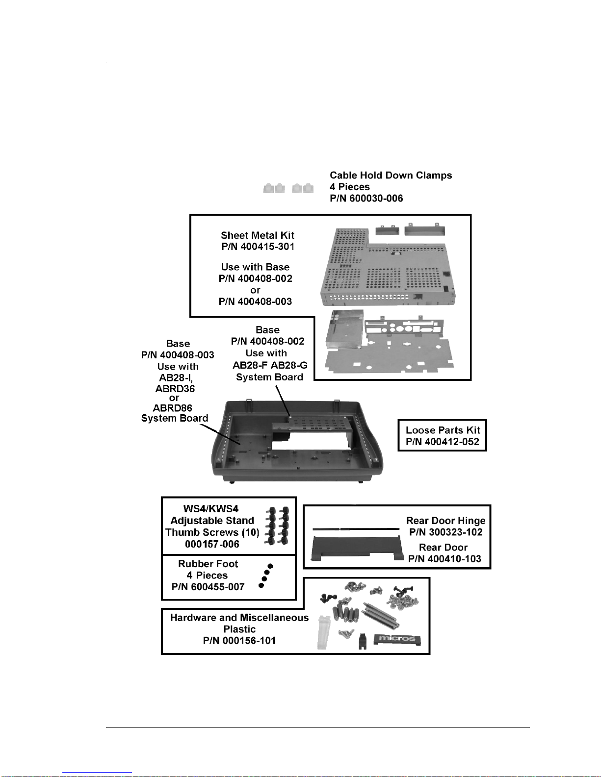
Figure 1-1 shows the spare parts related to the WS4 or WS4 LX workstation base.
Includes plastic, sheet metal, hardware and miscellaneous components.
Introduction to the WS4/WS4 LX FRUs
Base Casework - WS4 and WS4LX
Figure 1-1: WS4/WS4LX Base Casework Related Spare Parts
Workstation 4 and 4 LX Field Service Guide 1-3
Page 16

Introduction to the WS4/WS4 LX FRUs
Base Casework - WS4 and WS4LX
• Clamp, Cable Hold Down - P/N 600030-006.
Kit of four pieces. Mounted on the RF Shield Cover, one pair is used for the
display cable and toro id an d the second pair is used for the magnetic stri pe reader
interface cable and toroid. Base P/N 400408-003 does not require a toroid on the
mag stripe interface cable, so more recent units will have only two cable clamps
installed.
• Base Sheet Metal Kit - P/N 400415-301.
The Base Sheet Meta l Kit consists of the power supply tray, system board top and
bottom shield, original WS4 IO pane l, as well as the CF and PCMCIA card
covers. Use with Base P/N 400408-002 or 003. The IO plate is not compatible
with the ABRD86 (WS4 LX) System Board.
• Workstation Base - P/N 400408-002.
This base should be used for the AB28-F and AB28-G System Boards. Includes
pre-installed power button actuator. Does not include sheet metal components or
hardware. Use with Base Sheet Metal Kit P/N 400415-301 and hardware kit P/N
000156-101.
• Workstation Base - P/N 400408-003.
This base can be used for the AB28-I, ABRD36 and ABRD86 System Boards.
Includes pre-installed power button actuator. Does not include sheet metal or
hardware. Use with Hardware and Miscellaneous Plastic Kit 000156-101.
• Door Hinge, Rear - P/N 300323-102.
Compatible with all Workstation 4 and 4LX units.
• Door, Rear - P/N 400410-103.
The Rear Door covers the IO panel. Compatible with all Workstation 4 and 4LX
units.
• Thumbscrews, WS4/KWS4 Stand - P/N 00157-006.
Kit of ten thumbscrews used to secure the unit to the WS4 Adjustable Stand.
• Foot, Rubber - P/N 600455-007.
Kit of 4 pieces. Fits all versions of the WS4 Base.
• Hardware and Miscellaneous Plastic Kit - P/N 000156-101.
This kit includes all hardware for the base and top cover as well as the Operator
LED light pipe, and the MICROS l ogo badge located between the top and b ott om
workstation covers. Compatible with all Works tation 4 and 4LX units.
• Loose Parts Kit - P/N 400412-052.
Similar to the kit included with each workstation, it includes five 6” Tie Wraps,
five Employee/Diagnost ics Mag Cards, and one 2.5mm hex wr ench f or use on the
PCMCIA and CF card covers. AC power cable not included. Compatible with all
Workstation 4 and 4LX units.
1-4 Workstation 4 and 4 LX Field Service Guide
Page 17
System Boards and Components
This section starts with a discussion of each system board revision from the first
generation, through the first ‘ROHS’ compliant revision, then on to latest system
board, the WS4 LX.
In order to keep confusion to a mini mum, each sys tem board is refe renced by a model
designation printed on the board.
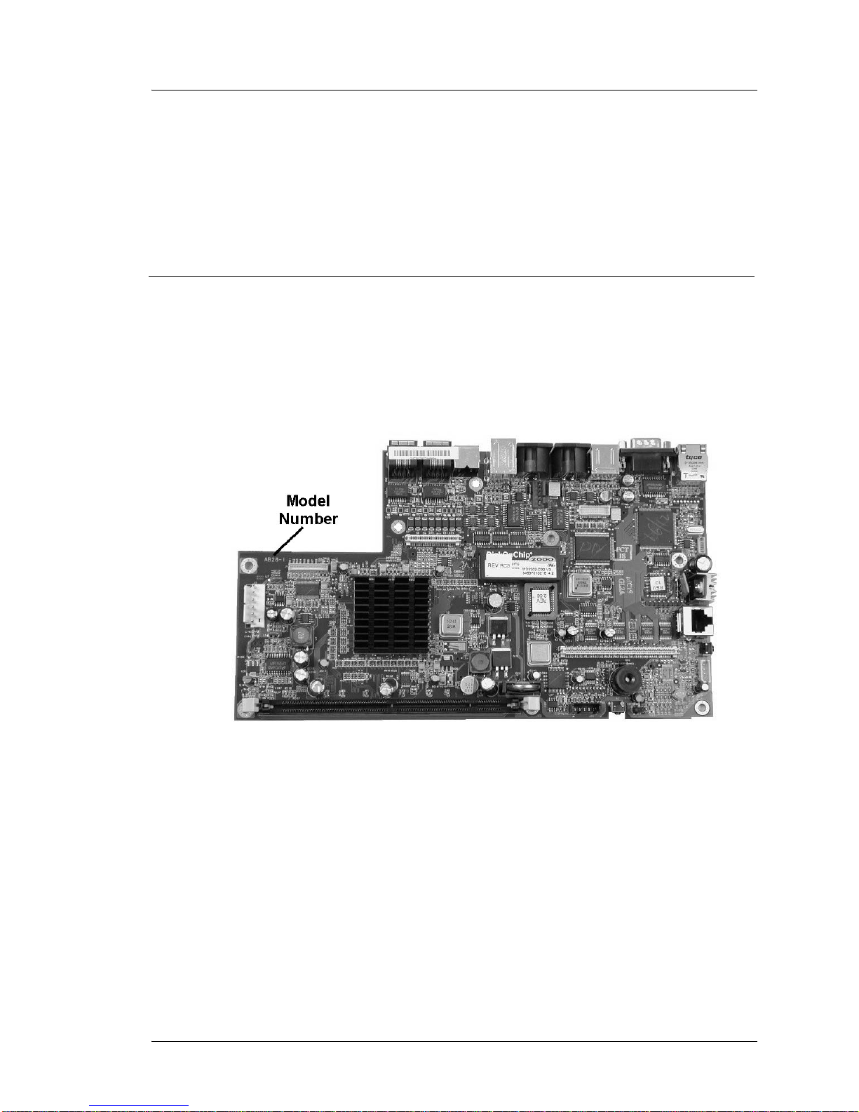
WS4 System Boards - A Short History
The AB28-’n’ designation (where ‘n’ represents the hardware revision), indicates the
‘original’ non-ROHS compliant series of WS4 System Boards. Close to 100000 units
were produced with the AB28 Series, including AB28-F, AB28-G and AB28-I.
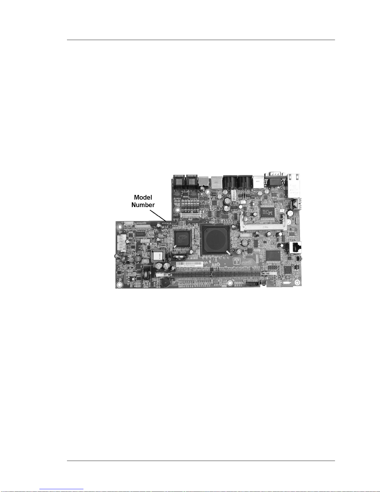
Figure 1-2 displays the AB28-I System Board, the most numerous example of the
AB28 series, and points out the location of the model number.
Introduction to the WS4/WS4 LX FRUs
System Boards and Components
Figure 1-2: The AB28 Series Workstation 4 System Board
The transition from AB28-F/G to AB28-I system boards combined with the change
from a Samsung LCD to a Sharp LCD forced changes in the LCD and backlight
cables. This is reflected in the section on replacement cables.
Another important change between the AB28-F/G, and AB28-I system boards is the
addition of a multiplexer on the COM 3 port, shared between the Mag Stripe Reader
and Customer Display port. The AB28-I System Board required updated platform
files in order for the mag stripe reade r and customer display interfaces to f unction
properly. Chapter 2 provides more detail about the multiplexer.
Workstation 4 and 4 LX Field Service Guide 1-5
Page 18
Introduction to the WS4/WS4 LX FRUs
System Boards and Components
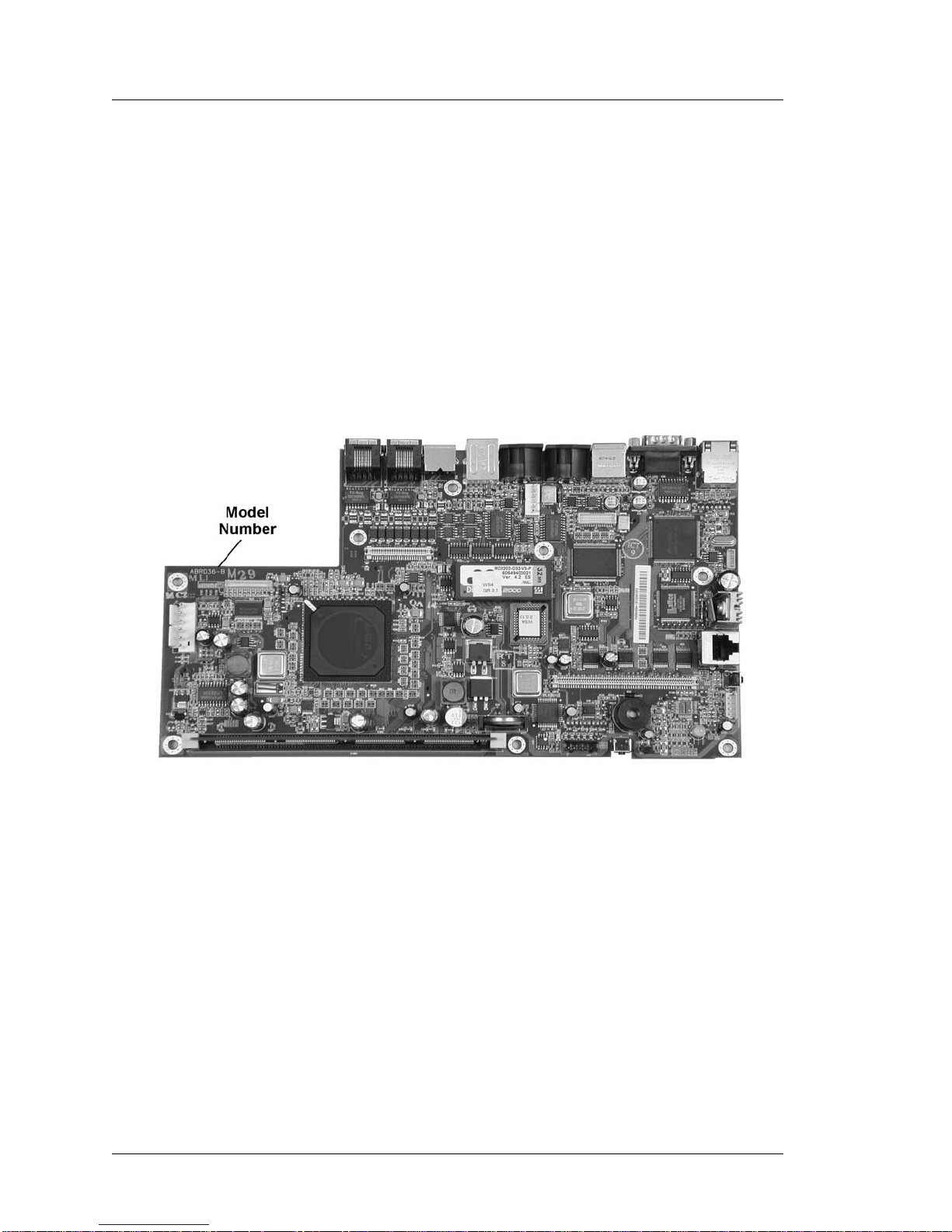
The first RoHS (Reduction of Hazardous Substances) compliant Workstation 4
System Board is designated ABRD36-B replacing the AB28 series. The Revision A
did not enter produ ction . The WS4 DiagUt ilit y views this bo ard as an ex tensi on of th e
AB28 series, displaying Revision ‘K’ in the ‘Hardware Revision’ field.
The primary difference between the ABRD36-B and AB28 series is the AMD Geode
SC3200 Processor packaging . Sever al ot her compone nts wer e also up dated to ‘ge t the
lead out,’ in addition to five other hazardous substances included in the RoHS
directive.
The ABRD36-B board is equivalent to the AB28-I board, using the same interface
cables, CF Card, DIMM, Boot Loader and Disk On Chip. Platform software GR2.2
(or GR2.3a if the LG61 LCD is used) is re qui red. Figure 1-3 displays a sample of this
board and the model number location.
Figure 1-3: The ABRD36-B or Rev K Workstation 4 System Board
The board pictured above doe s not i nclude a proce ssor he at si nk, b ut the first unit s did
include one. The AMD Geode SC3200 packaging used on the AB28 board series did
require a passive heat sink to maintain internal temp eratures and this carried o ver to
the initial production of the ABRD36 system board. However, subsequent testing in
the heat chamber indicated that the ROHS packaging offered improved heat
dissipation and heat sink was not required.
Production of the ABRD36 board ends with the int r oduc ti on of th e Workstation 4 LX
System Board.
1-6 Workstation 4 and 4 LX Field Service Guide
Page 19
Introduction to the WS4/WS4 LX FRUs
System Boards and Components
The Workstat ion 4 LX System Board
The Workstation 4 LX System Board is also ROHS compliant and uses the
designation ABRD86-n, where ‘n’ represents the hardware revision. More than just a
board ‘spin’, the LX is a new hardware architecture - requiring a new API, and
platform files. The CAL Client and MICROS applications consider it a new terminal.
Chapter 4 includes a technical overview of this board.
The LX System Board is based on the x86 compatible AMD Geode LX800 processor
and CS5536 Companion Device. This processor, when combined with USB Flash
Drive technology to replace the relativity slow (and soon to be EOL) Disk On Chip
results in a unit that benchmarks up to three times faster than the original WS4 with a
MICROS POS application. Figure 1-4 displays a sample of the ABRD86-D System
Board and model number location.
Figure 1-4: The Workstation 4 LX System Board - ABRD86
Highlighted Changes:
• Blue Operator LED distinguishes the WS4 LX from the original WS4.
• Disk On Chip replaced with USB based flash drive.
• The PCMCIA Socket is replaced by the Mini-PCI socket, to accommodate a
Mini-PCI wireless card. The WS4 LX IO Plate includes a cut-out for an SMA
style antenna connector included in the kit.
• The PS/2 Mouse and Keyboard connectors are replaced by two additional USB
Ports. This means that an IO plate fro m the original WS4 will not fit the LX
System Board.
• The Ethernet Controller supports 1Gbit LANs.
• General Software’s Embedded BIOS 2000 BIOS replaces the original WS4 Boot
Loader. It provides the environment for creating custom pre-boot firmware
utilities such Windows CE Factory Restore.
Workstation 4 and 4 LX Field Service Guide 1-7
Page 20
Introduction to the WS4/WS4 LX FRUs
Workstation 4 System Board and Components
Workstation 4 System Board and Components
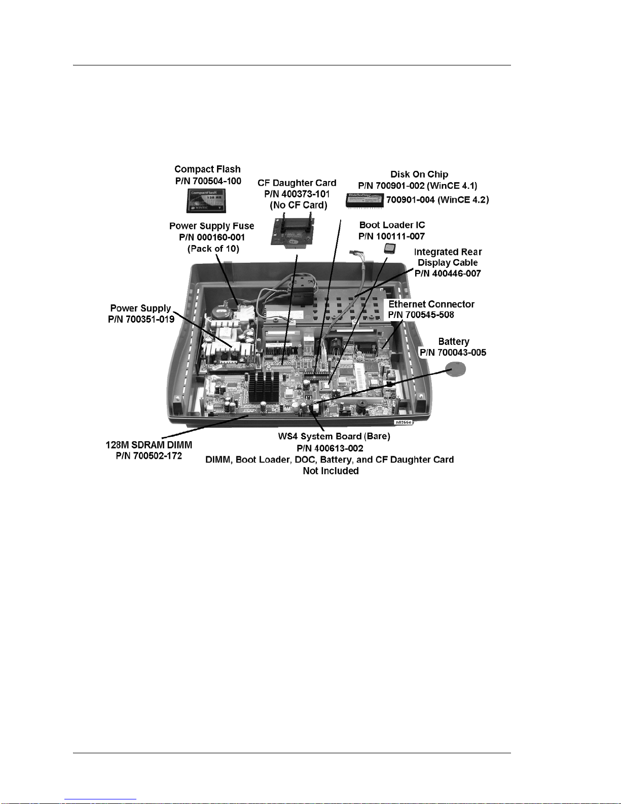
Figure 1-5 shows the original WS4 with the AB28 series or ABRD36 system board
and components.
Figure 1-5: Original Workstation 4 System Board and Components
• Bare Workstation 4 System Board - P/N 400613-002.
Bare ABRD36 system board does not inc lude DIMM, Boot Loader, Disk On Chip
Battery, CF Daughter Card and Processor heatsink. The ROHS compliant WS4
system board designated ABRD36-B, (Revision B) is the current replacement
board for the original WS4.
Physically, the ABRD36 system board is a drop-in replacement for the AB28-I
system board, using the same interface cables, DOC, boot loader, CF card, and
DIMMs. If this board replace s the AB28-F or AB28-G sys tem boards, see Cha pter
6 to install the LCD and backlight cables with the proper ‘offset.’
• DIMM, 128M SDRAM - P/N 700502-172.
Replacement 128M SDRAM DIMM. Compatible with the AB28 and ABRD36
boards, as well as the KW S4 system board. Not compatible with the LX Syste m
board.
1-8 Workstation 4 and 4 LX Field Service Guide
Page 21

Introduction to the WS4/WS4 LX FRUs
Workstation 4 System Board and Components
• Compact Flash Daughter Card - P/N 400373-101.
The CF Daughter Card attaches to J4 on AB28 and ABRD36 Sys tem Board s. The
CF Card, cover and mounti ng hardware not included. This part is a ls o compatible
with the KWS4, PCWS 2010, WS4 LX, and WS5.
• IC, Compact Flash Card - P/N 700504-100.
A blank, formatted 256M Compact Flash card. Can be used in any Workstation 4,
or Workstation 4 LX.
• IC, U19, Disk On Chip - P/N 700901-002 or P/N 700901-004.
32M Disk On Chip in 32-Pin DIP package. The -002 part includes a pre-loaded
WinCE 4.1 image and the -004 part includes a pre-loaded WinCE 4.2 image.
Installs in socket U19 on the AB28 board or U18 on th e ABRD36 System Boards.
Not compatible with the ABRD86 System board.
• IC, U24, Boot loader, Preprogrammed - P/N 100111-007.
39VF020 256M Flash Memory Device contains workstation 4 boot loader.
Installs in socket U24. Compatible with AB28 and ABRD36 System Boards. Not
compatible with the ABRD86 (WS4 LX) System board.
• Cable, Rear LCD Customer, Integrated - P/N 400446-007.
This cable connects to J1 on the system board and attaches to the cable from the
optional Integrated LCD Customer Display. See page 1-24 for more LCD
Customer Display cables. Can als o be used in the KWS4 and WS4 LX.
• Ethernet Connector - P/N 700545-508.
Replacement System Board Connector CN9, for the 10/100 Ethernet Interface.
Compatible with the AB28 and ABRD3 6 sy st em boa rds . Not co mp at ibl e wi th th e
ABRD86 System Board.
• Battery - P/N 700043-005.
CR2032 3V Lithium Coin Cell. This battery is also used on the WS4 LX, PCWS
2010, KWS4, and PCWS Eclipse system boards.
• Power Supply - P/N 700351-019.
65W open frame power supply with +5V, +12V and -12V outputs. This power
supply is compatible with Workstation 4 and Workstation 4 LX units.
• Power Supply Fuse, Kit of 10 pcs. - P/N 000160-001.
3.15A, 250V AC Input fuse with pigtail leads for WS4 and WS4 LX Power
Supply P/N 700351-019.
Workstation 4 and 4 LX Field Service Guide 1-9
Page 22
Introduction to the WS4/WS4 LX FRUs
Workstation 4 LX System Board and Component s
Workstation 4 LX System Board and Components
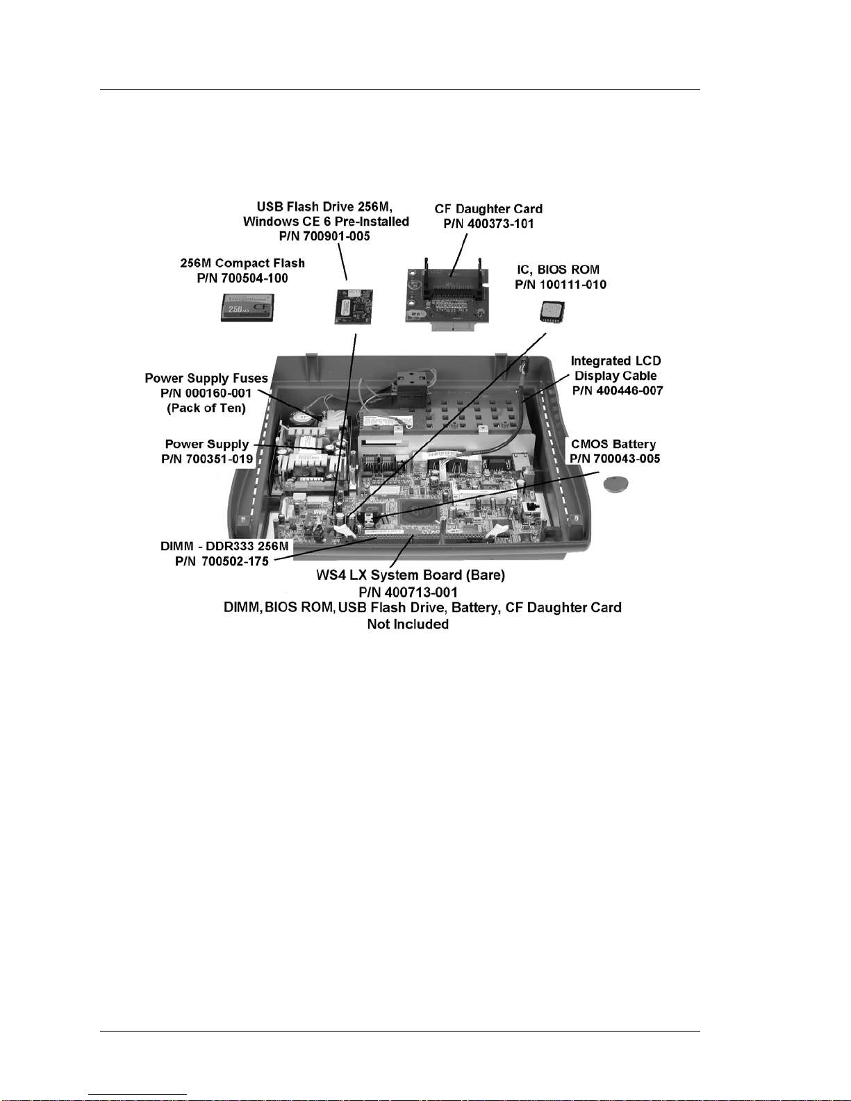
Figure 1-6 shows the WS4 LX System Board ABRD86 and components.
Figure 1-6: WS4 LX System Board and Components
• Main Board, Bare, WS4 LX System Board, P/N 400713-001.
Bare ABRD86 system board does not include DIMM, BIOS ROM, USB Flash
Drive, CMOS battery, or CF Daughter Card.
As discussed in the previous section, the ABRD86 System Board is not a direct
replacement for the original Workstation 4 system boards, AB28 or ABRD36.
• USB Flash Drive, 256M, Pre-Programmed, WS4 LX - P/N 700901-005.
256M USB Flash Drive is pre-loaded with the Windows Embedded CE 6.0
operating system, platform files and utilities. Installs on system board header J5.
Not compatible with the AB28 or ABRD36 System Boards.
• IC, BIOS ROM, WS4 LX - P/N 100111-010.
The pre-programmed 1M BIOS ROM installs in socke t U35. Not compatibl e with
the AB28 and ABRD36 System Boards.
1-10 Workstation 4 and 4 LX Field Service Guide
Page 23

Introduction to the WS4/WS4 LX FRUs
Workstatio n 4 LX System Board and Components
• Compact Flash Daughter Card - P/N 400373-101.
The CF Daughter Card plugs into socket IDE1 on the LX Sys tem Board a nd J 4 on
older System Boards. Cover and mounting hardware not included.
• IC, Compact Flash Card - P/N 700504-100.
A blank, formatted 256M Co mpact Fl ash Card. Can be used in any Workstation 4
or Workstation 4 LX.
• DIMM, DDR333 256M - P/N 700502-175.
Replacement DIMM. Approved devices include Wintec
WD1UN256X808-333B-QC-RA and Unigen UG732D6688KK-DHFMSE. Not
compatible with AB28 and ABRD36 System Boards.
• Cable, Rear LCD Customer, Integrated - P/N 400446-007.
This cable is pre-installed on all Workstation 4 LX System Boards. It attaches
between J1 on the System Board to the optional Integrated LCD Customer
Display. Compatible with the WS4 and KWS4.
• Battery - P/N 7000043-005.
CR2032 3V Lithium Coin Cell. This battery is also used on the WS4, WS5,
PCWS 2010, KWS4, and PCWS Eclipse System Boards.
• Power Supply - P/N 700351-019.
65W open frame power supply with +5V, +12V and -12V outputs. Compatible
with the WS4 and WS4 LX.
• Power Supply Fuse, Kit of 10 pcs. - P/N 000160-001.
3.15A, 250V AC Input fuse with pigtail leads for P/N 700351-019.
Workstation 4 and 4 LX Field Service Guide 1-11
Page 24
Introduction to the WS4/WS4 LX FRUs
Cables and Toroids
Cables and Toroids
This section presents the cables available for the WS4 and adds the WS4 LX.
Considering the original AB28 series system board connector changes, three LCD
panels and the recent introduction of the WS4 LX System board, a total of four LCD
interface cable s and two ba cklig ht int erfac e cable s are av ail able. The WS4 LX sys tem
board (ABRD86) uses the same LCD and bac klight ca bles as the WS4 Rev I (AB28-I)
or ABRD36-B system boards. The table below summarizes the LCD and backlight
cable part numbers, based on the system board type, revision and the Samsung or
Sharp CD panels.
System
Board
AB28-F
AB28-G
AB28-I
ABRD36-B
ABRD86
Samsung
LCD
300331-204 300331-202 300331-103
300331-201 300331-203 300331-200
300331-201 300331-203 300331-200
N/A 300331-203 300331-200
Sharp LCD
(LG41,
LG61)
Backlight
Inverter
Each cable is listed individually in the following pages.
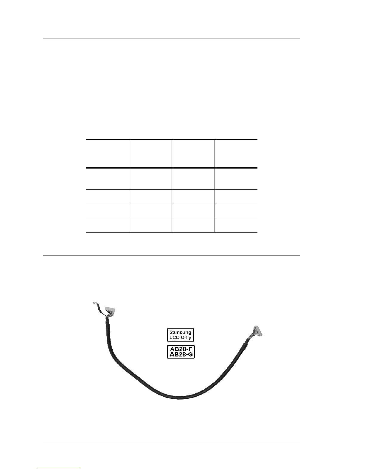
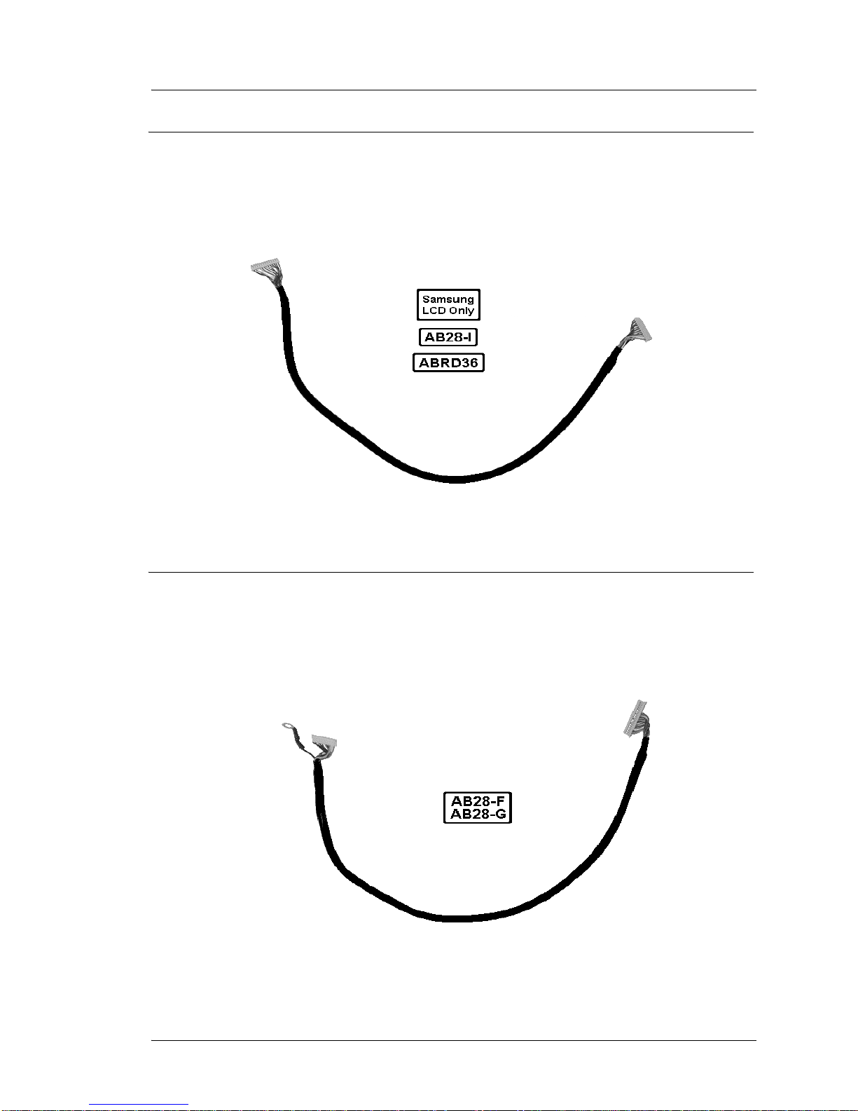
Cable, Assembly LCD Display, REV F/G, BD, WS4 - P/N 300331-204
The cable shown in Figure 1-7 connects between the EOL Samsung LCD LVDS
Board and system boards AB28-F and AB28-G. This cable is not compatible with a
Sharp LCD.
Figure 1-7: Samsung LCD Cable for AB28-F and AB28-G System Boards
1-12 Workstation 4 and 4 LX Field Service Guide
Page 25
Introduction to the WS4/WS4 LX FRUs
Cables and Toroids
Cable, Samsung LCD Display, WS4 REV I, WS4 ROHS - P/N 300331-201
The cable shown in Figure 1-8 connects between the EOL Samsung LCD LVDS
Board and System Boar d AB28 -I . This cable is not compatible with a Sharp LCD and
system boards AB28-F and AB28-G.
Figure 1-8: Samsung LCD Cable for AB28-I or ARBD36 System Boards
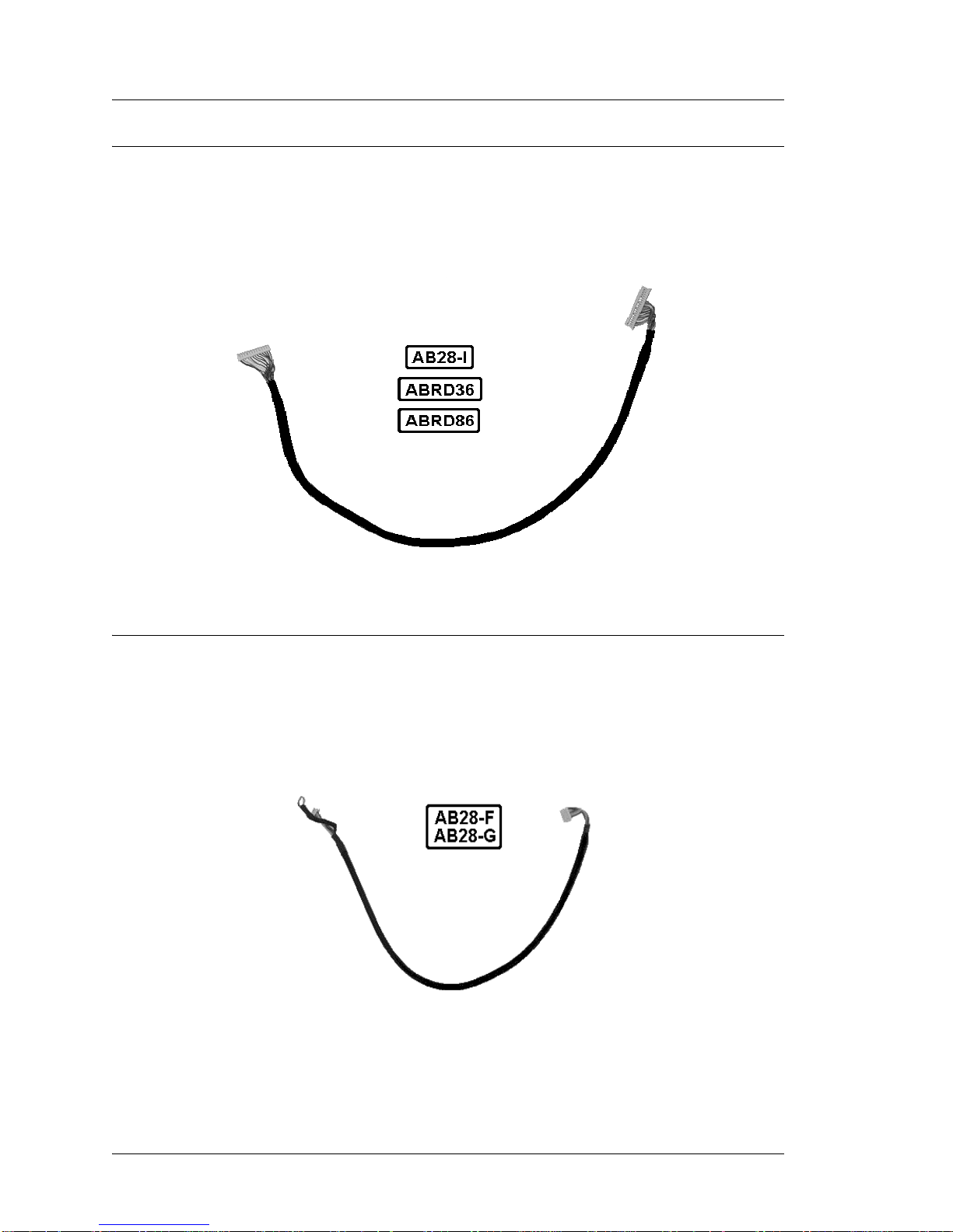
Cable, Sharp LCD Display, REV F/G BD, WS4 - P/N 300331-202
The cable shown in Figur e 1 -9 c onnects a Sharp LCD to older system boards AB28-F
and AB28-G. This cable is not compatible with the Samsung LCD, the AB28-I,
ABRD36 and ABRD86 system boards.
Figure 1-9: Sharp LCD Cable for AB28-F or AB28-G System Boards
Workstation 4 and 4 LX Field Service Guide 1-13
Page 26
Introduction to the WS4/WS4 LX FRUs
Cables and Toroids
Cable, Sharp LCD Display, WS4 Rev I, ROHS, or WS4 LX - P/N 300331-203
The cable shown in Figure 1-10 con nects a Sharp LCD to WS4 System Board AB28- I,
ABRD36, and ABRD86. Not compatible with Samsung LCDs and the AB28-F/G
System Boards.
Figure 1-10: Sharp LCD Cable for AB28-I and later System Boards
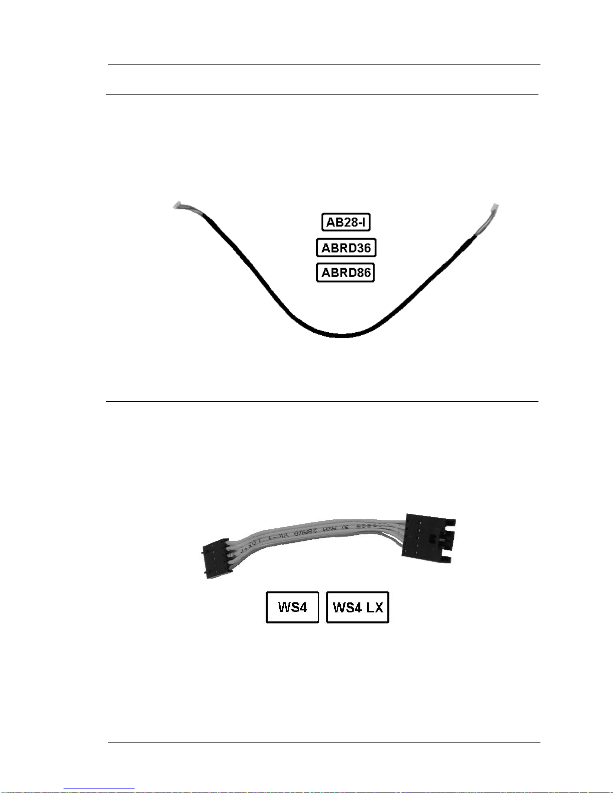
Cable, Inverter, F/G BD, WS4 - P/N 300331-103
The cable shown in Figure 1-11 connects between the backlight inverter board and
system boards AB28-F and AB28-G only. Not compatible with AB28-I, ABRD36 and
ABRD86 system boards.
Figure 1-11: Inverter Cable for WS4 AB28-F and AB28-G System Boards
1-14 Workstation 4 and 4 LX Field Service Guide
Page 27
Introduction to the WS4/WS4 LX FRUs
Cable, Inverter to REV I BD, WS4 or WS4 LX - P/N 300331-200
The cable shown in Figure 1-12 connects between the backlight inverter board and
system boards AB28-I, ABRD36, and ABRD86. This cable is not compatible with
WS4 System Boards AB28-F and AB28-G.
Cables and Toroids
Figure 1-12: Inverter Cable for WS4 Rev I, ROHS and WS4 LX System Boards
Touchscreen Extension Cable - P/N 300331-350
This cable connects between the system board and the touchscreen ribbon cable. The
cable shown in the illustration below is an improved version of the original extension
cable and is compatible with all WS4 and WS4 LX system boards.
Figure 1-13: Touchscreen Extension Cable
Workstation 4 and 4 LX Field Service Guide 1-15
Page 28
Introduction to the WS4/WS4 LX FRUs
Cables and Toroids
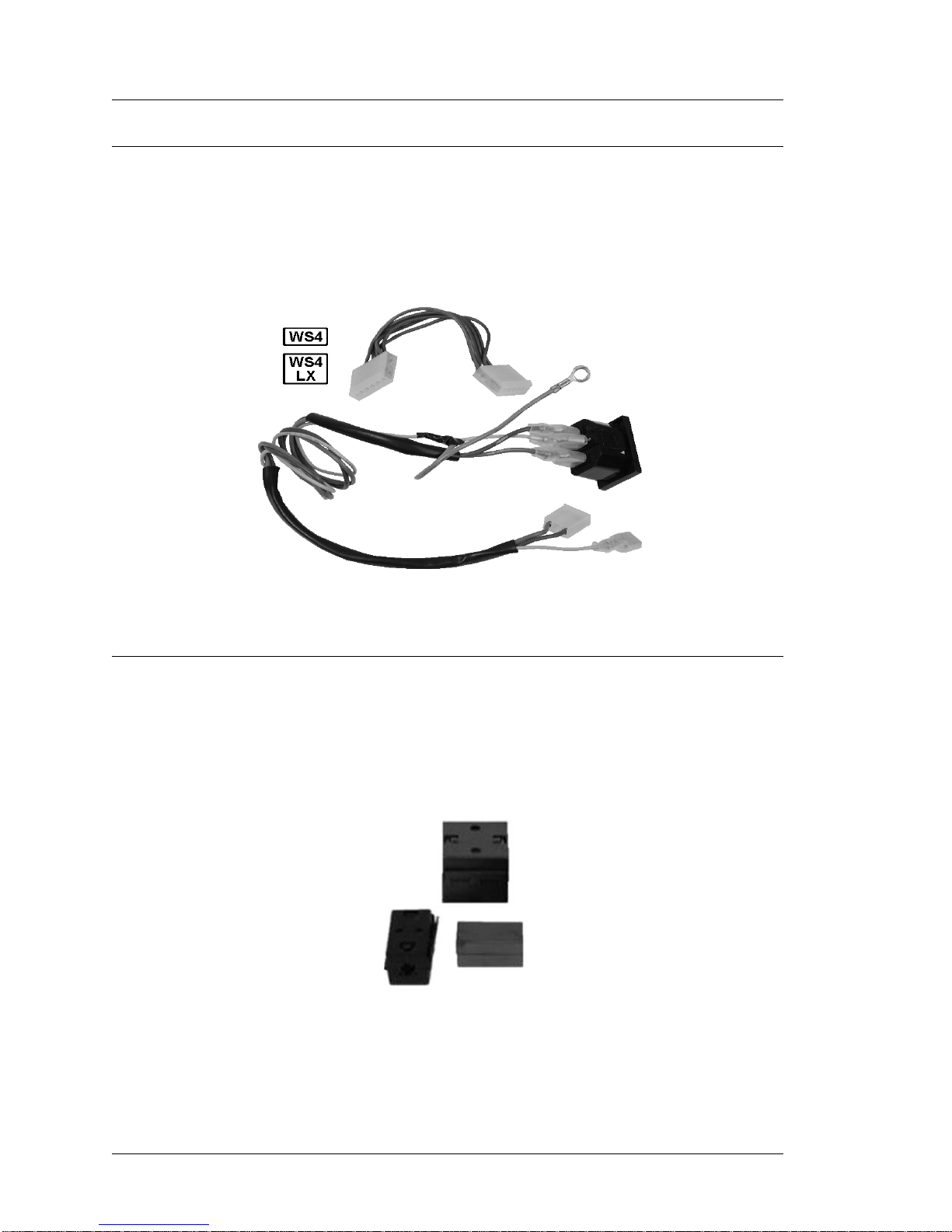
Cable Kit, Power In - Power Out, AC Conn - P/N 000170-003
Figure 1-14 displays the Power In and Power Out Cable Kit. It consists of the AC
input cable assembly and the power supply to syst em board cable. The Power -In cab le
does not include a toroid. It is part of toroid kit P/N 700791-001, below. Both cables
are compatible with all WS4s including the WS4 LX .
Figure 1-14: WS4 and WS4 LX AC Input and Power Supply Cable Kit
Toroid Kit, Display, MSR, and AC Power - P/N 700791-001
Kit of three toroids. One each for the LCD interface cable, mag stripe reader cable,
and AC Power In cable assembly. WS4s that use the AB28-I, ABRD36 or ABRD86
system boards and the 400408-003 base do not require a toroid on the MSR cable.
Figure 1-15: WS4 and WS4 LX Toroid Kit
1-16 Workstation 4 and 4 LX Field Service Guide
Page 29
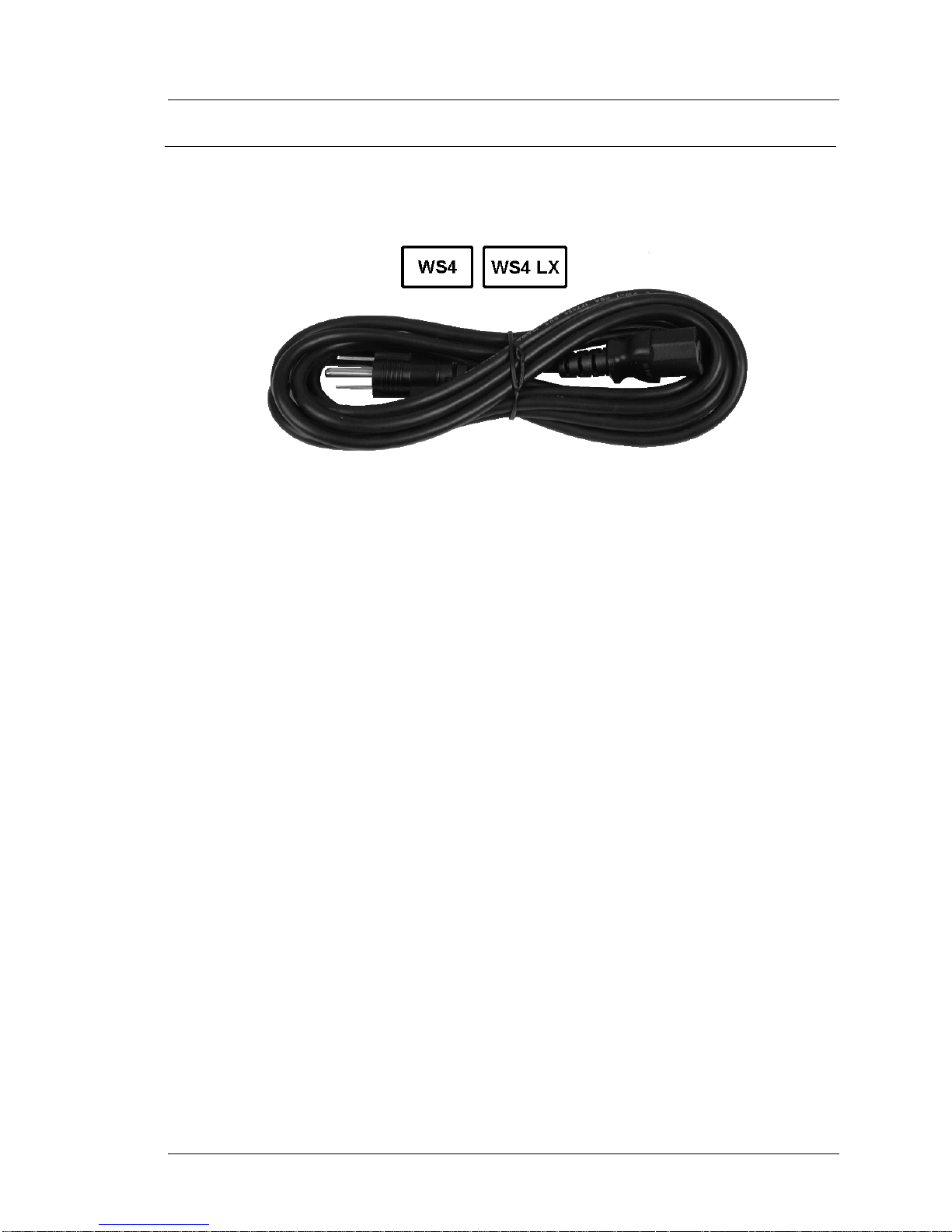
AC Power Input Cable - P/N 200153-001
Replacement AC Power Cable for Workstation 4 and Workstation 4 LX.
Figure 1-16: Replacement AC Power Cable
Introduction to the WS4/WS4 LX FRUs
Cables and Toroids
Workstation 4 and 4 LX Field Service Guide 1-17
Page 30
Introduction to the WS4/WS4 LX FRUs
Workstation 4 and 4 LX - LCD/Touchscreen/Mag Stripe Reader
Workstation 4 and 4 LX - LCD/Touchscreen/Mag Stripe Reader
This section lists all components in the WS4 or WS4 LX top cover, including the
LCD, touchscreen, and mag stripe reader.
Samsung LCD Related
The Samsung LTM121SI-T01 LCD panel is no longer av ailab le, EOL in l ate 2 004. To
replace the Samsung LCD panel, order kit P/N 000160-100. More information about
the kit contents is listed below.
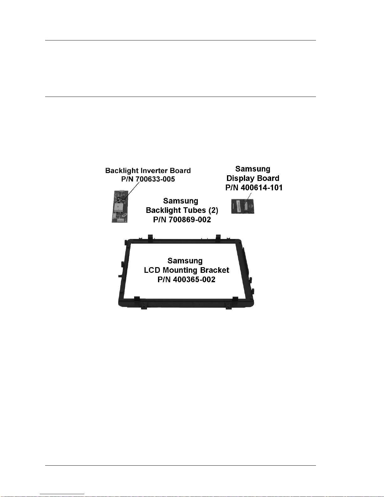
While the Samsung LCD panel itse lf is no longer available, the components shown in
Figure 1-17 are available.
Figure 1-17: Samsung LCD Related Spares
• LCD Conversion Kit - P/N 000160-100.
The kit consists of a Sharp LQ121S1LG41 or LG61 Panel, LCD mounting
bracket, and interface cable. MD0011-003, included in the kit provides
installatio n instructio ns.
• Samsung LCD Mounting Bracket - P/N 400365-002.
This LCD Mounting bracket is specific to the Samsung LTM121SI-T01 12.1”
TFT LCD Panel.
• Samsung Video Display Board - P/N 400614-101.
Also known as the LVDS Receiver Board, XB34. This board attaches directly to
the input connector of the Samsung LCD. This board is not required for Sharp
LCDs; the LVDS receiver is built-in.
1-18 Workstation 4 and 4 LX Field Service Guide
Page 31

Introduction to the WS4/WS4 LX FRUs
Workstation 4 and 4 LX - LCD/Touchscreen/Mag Stripe Reader
• Backlight Inverter Board - P/N 700633-005.
This board attaches to the LCD bracket and powers the Samsung or Sharp LCD
backlight tubes. Two versions of the backlight inverter board now exist. The
original board can be identified by the number ‘XB33’ located near the input
connector J1.
The ROHS compliant version of the backlight inverter is the same MICROS P/N
as the previous board, but includes a new transformer that operates at a higher
frequency. This board can be identified by the model number ‘XBRB33’
silk-screened near the input connector J1.
The increased operating frequency of the inverter circuit is optimized for the
Sharp LG41 and later the LG61 LCD, and results in diminished backlight
brightness if used with the EOL Samsung LCD and GR 2.0 platform software.
The low brightness levels affect the DIM and NORMAL brightness settings and
are inherent to the new transformer’s operating characteristics. See the ‘Other
Platform Fil es and Folders’ section of Chapter 3 for more informatio n.
Workstation 4 and 4 LX Field Service Guide 1-19
Page 32

Introduction to the WS4/WS4 LX FRUs
Workstation 4 and 4 LX - LCD/Touchscreen/Mag Stripe Reader
Sharp LCD Related
Figure 1-18 shows the spare parts available for the Sharp LCD. These items are
compatible with both the WS4 and WS4 LX
.
Figure 1-18: Sharp LCD Related FRUs - WS4 and WS4 LX
• Sharp LCD Panel - P/N 700594-030.
The Sharp LCD Model LQ121S1LG61 (LG61) replaces the Sharp Model
LQ121S1LG41 (LG41). Each i s phy sic ally and e lectr ical ly compa tibl e - u sing the
same interface cable and bracket. Software or driver changes are not required.
Vermont LCD Notice
This product contains mercury and may only be disposed of
after the proper removal and disposal of the lamps.
• Sharp LCD Bracket - P/N 300264-301.
This bracket is unique to the Sharp LQ121S1LG41 or LG61 TFT LCD Panel.
• Backlight Inverter Board - P/N 700633-005.
This board attaches to the LCD bracket and powers the LCD backlight tubes. Two
versions of the backlight inverter board now exist. The ROHS compliant version
of the backlight invert er introduc ed at the same time as the ABRD36 system board
uses the same MICROS P/N as the previous board. Howeve r this board has a new
transformer that operates at a higher frequency optimized for the Sharp LG41 or
LG61 LCD. This board is designated by the model number ‘XBRB33’ located
near input connector J1.
1-20 Workstation 4 and 4 LX Field Service Guide
Page 33

Workstation 4 and 4 LX - LCD/Touchscreen/Mag Stripe Reader
Touchscreen and Front Cover Plastic
Figure 1-19, shows the part numbers for the touch screen glass, gasket, and the top
cover plastic. These items are compatible with the WS4 and WS4 LX.
Introduction to the WS4/WS4 LX FRUs
Figure 1-19: WS4 and WS4 LX Touchscreen and Top Cover
• Touchscreen Glass - P/N 400386-011.
EloTouch Systems 5-wire resistive touchscreen glass.
• Touchscreen Gasket - P/N 600537-127.
The touchscreen gasket fits in a groove in the top cover. The same gasket is used
in the PCWS Eclipse and 2010 12.1” LCD Head.
• Top Cover - P/N 400409-002.
The Top Cover Plastic. Does not include hardware or Operator LED light pipe.
All hardware and the light pipe are included with kit P/N 000156-101.
Workstation 4 and 4 LX Field Service Guide 1-21
Page 34

Introduction to the WS4/WS4 LX FRUs
Workstation 4 and 4 LX - LCD/Touchscreen/Mag Stripe Reader
Top Cover - Mag Stripe Reader Assem b ly and Cover - WS4 and WS4 LX
Figure 1-20 shows the MSR and related components installed in the top cover.
Figure 1-20: Magnetic Stripe Reader FRUs - WS4 and WS4 LX
• Mag Stripe Reader Assembly - P/N 700293-110.
Three-track 90mm RS232 compati ble reader assembly. This is the sam e reader
used by the PCWS Eclipse and 2010. Compatible with the WS4 and WS4 LX.
System Boards prior to AB28-I and Base P/N 400408-002 use a toroid on this
cable.
• Mag Stripe Reader Mounting Kit - P/N 700789-101.
The kit consists of the black plastic spill cover, end brackets and hardware.
Compatible with the WS4 and WS4 LX.
1-22 Workstation 4 and 4 LX Field Service Guide
Page 35

LCD Customer Display
This section lists the available FRU’s for the LCD Customer Display. See Chapter 6
for instructions on removing and replacing these items. The WS4, KWS4, WS4 LX
and WS5 support this display.
LCD Interface Board - P/N 400702-001
The LCD Customer Display Interface Board is used for the Integr ated, Pole and
Adjustable S tand Pole mounted dis play. This board is also drives t he Operat or Displa y
in the KWS4.
Introduction to the WS4/WS4 LX FRUs
LCD Customer Display
Figure 1-21: LCD Customer Display Interface Board
LCD Module, Optrex - P/N 700594-117
The 240x64 Monochrome LCD Module is used for the Rear and Pole Mount LCD
Customer Display. It is also used for the Operator Display on the KWS4.
Figure 1-22: Optrex LCD Module for the LCD Customer Display
Workstation 4 and 4 LX Field Service Guide 1-23
Page 36

Introduction to the WS4/WS4 LX FRUs
LCD Customer Display
Cable, LCD Pole and Rear Display Head - P/N 300331-251
This replacement cable connects between the LCD Interface Board in the rear or pole
LCD display housing to cable 400446-007 (Integrated/Rear) or 300331-250 (Pole).
Figure 1-23: Replacement LCD Customer Display Cable
Cable Extension, LCD Pole Display - P/N 300331-250
This cable is installed in the pole and connects between 300331-251 (above) and the
WS4, WS4 LX, WS5 or KWS4 I/O Panel. It is approximately 6 feet (183 cm) in
length.
Refer to Figure 1-5 for the P/N of the Customer Display cable that attache s to the
system board.
Figure 1-24: Replacement LCD Pole Extension Cable
1-24 Workstation 4 and 4 LX Field Service Guide
Page 37

Introduction to the WS4/WS4 LX FRUs
LCD Customer Display
Kit, Front/Rear Cover, /w Lens, Screws, Pole Mount Hinge - P/N 000160-010
LCD Customer Display housing kit with Front and Rear Plastic covers, pole mount
and pre-installed 2nd generation hinge assembly.
Figure 1-25: Pole Display Plastic Replacement Kit
Kit, Front/Rear Cover, /w Lens, Screws, Rear Mount Hinge - P/N 000160-011
LCD Customer Display housing kit with Front and Rear Plastic covers, integrated
mounting bracket, and pre-installed 2nd generation hinge assembly.
Workstation 4 and 4 LX Field Service Guide 1-25
Figure 1-26: Rear Display Plastic Replacement Kit
Page 38

Introduction to the WS4/WS4 LX FRUs
LCD Customer Display
1-26 Workstation 4 and 4 LX Field Service Guide
Page 39

WS4 Technical Overview
This Chapter contains the Workstation 4 System Board AB28 and ABRD36
technical descriptions. Refer to Chapter 4 for more information about the
Workstation 4 LX System Board, ABRD86.
Chapter 2
In this chapter
Workstation 4 System Block Diagrams........................................................2-2
SC3200 GX1 Processor, Video Processor, Core Logic and Super IO......... 2-5
PCI and Sub-ISA Bus Interface ................................................................... 2-8
SC3200 Super I/O.......................................................................................2-11
PC87360 Super IO..................................................................................... 2-12
TFT LCD Interface.................................................... ......... ......... .............. 2-17
Touchscreen Interface................................................................................ 2-20
Optional PCMCIA Daughter Card ............................................................ 2-21
Optional Mini PCI Daughter Card............................................................. 2-22
Complex Programmable Logic Device (CPLD)........................................ 2-23
DP83815 10/100 Mbps PCI Ethernet Controller....................................... 2-32
RS422 Port A and RS422 B....................................................................... 2-35
Customer Display/Mag Card Reader Port (COM3).................................. 2-38
Optional LCD Customer Display .............................................................. 2-44
Workstation 4 and 4 LX Field Service Guide 2-1
Page 40

WS4 Technical Overview
Workstation 4 System Block Diagrams
Workstation 4 System Block Diagrams
In the following pages, the three major configurations of the original Workstation 4
are presented. Each highlights the system board and LCD configuration as it changes
over time. Figure 2-1 shows the initial configuration of the WS4 with System Board
AB28-F/G and a Samsung LCD panel.
Figure 2-1: WS4 Block Diagram /w System Boards AB28-F or AB28-G and Samsung LCD Panel
Functionally, there is very little difference between AB28-F and AB28-G. The
majority of changes were implemented to improve EMI emissions, and lower
manufacturing costs.
The illustration also shows the Samsung LCD panel and companion LVDS Receiver
Board, designated XB34.
This configuration was produced up to August 2004.
2-2 Workstation 4 and 4 LX Field Service Guide
Page 41

WS4 Technical Overview
Workstation 4 System Block Diagrams
Figure 2-2 shows a block diagram of the WS4 based on th e AB28-I System Board and
the Sharp ‘LG41’ LCD.
Figure 2-2: WS4 Block Diagram /w AB28-I System Board and Sharp LCD Panel
The AB28-I System Board int roduce s the COM3 Mult iple xer in order to ful ly sup port
the MICROS LCD Customer Display, introduced in late 2004. More information on
this change can be found on page 2-38.
This configuration, cons isting of the AB28-I System Board, Backlight Invert er Board
XB33, and CF Daughter Card XB36, and Shar p LCD were produced between August
2004 and June 2006.
The Sharp LCD includes a built-in LVDS receiver, and does not require the XB34
LVDS Receiver Board. The AB28-I System Board uses different LCD and Backlight
interfaces cables than the AB28-F and AB28-G System Boards. See Chapter 1.
T o sup port th e COM3 Multiple xer for the MSR an d customer displ ays, the GR 1.2 (or
later) platform files must be installed on the works t ation. The m ajority of these units
were shipped with the GR 2.0 or 2.1 platform.
Workstation 4 and 4 LX Field Service Guide 2-3
Page 42

WS4 Technical Overview
Workstation 4 System Block Diagrams
Figure 2-3 displays the third variation of the original WS4, based on the ABRD36
System Board and Sharp LG41 LCD.
Figure 2-3: WS4 Block Diagram /w ABRD36 System Board and Sharp LCD Panel
The ABRD36 System Board is combined with Backlight Inverter Board XBRB33,
and CF Daughter Card XBRB36 to complete a ROHS compliant WS4.
The ABRD36 system board is compatible with the AB28-I board as a drop-in
replacement (each uses the same LCD and Backlight Inverter cables), but it requires
the GR2.2 Platform software to fun ction correctly.
The configuration shown above entered production in approximately June 2006 and
continued until the release of the Workstation 4 LX in July 2007. Non-ROHS
compliant Workstation 4s were also produced during this period.
Over 172,000 Workstation 4s were produced in one of the three basic configurations
presented here. Workstation 4 EOL occurred in July 2007, with hardware support
continuing through late 2012. See Chapter 4 for more information about the WS4 LX
System Board.
2-4 Workstation 4 and 4 LX Field Service Guide
Page 43

WS4 Technical Overview
SC3200 GX1 Processor, Video Processor , Core Logi c and Super IO
SC3200 GX1 Processor, Video Processor, Core Logic and Super IO
REF: AB28/ABRD36 - Sheets 1, 2 and 3
The SC3200 was originally a member of National Semiconductor Corp. ‘WebPad On
A Chip’ family of highly integrated x86 system devices. In mid-2003, Advanced
Micro Devices (AMD) purchased t he Geo de line fr om Nationa l. The SC3200 consist s
of a GX1 processor integrated with a TFT LCD video controller, x86 compatible PC
core logic block, and Super IO component shown in the Figur e 2-4 below. Features of
each section are highlighted in the paragraphs that follow.
Workstation 4 and 4 LX Field Service Guide 2-5
Figure 2-4: Geode SC3200 Block Diagram
Page 44

WS4 Technical Overview
SC3200 GX1 Processor, Video Processor, Core Logic and Super IO
GX1 Processor
The Geode GX1 combines advanced CPU performance with MMX™ support,
accelerated 2D graphics, a 64-bit syn chronou s DRAM (SDRAM) interfac e contr oller,
PCI Bus Controller, and a display controller.
• 32-bit, x86, 266Mhz clock speed, with MMX™ compatible instruction set.
• 16 KB unified L1 cache
• Integrated floating point unit (FPU)
• Re-entrant SMM enhanced for VSA.
2D Graphics Accelerator
• Accelerates BitBLTs, line draw and text
• Supports all 256 raster operations
• Supports transparent BLTs
• Runs at the same frequency as the GX1
Memory Controller
• 64-Bit SDRAM Interface
• 66Mhz to 100 Mhz frequency range. The Workstation 4 runs at 78Mhz.
• Direct interface to CPU/cache, display controller and 2D graphics accelerator
• Supports clock suspend and power-down/self refresh
• Up to 8 SDRAM devices or one DIMM/SODIM socket.
Display Controller
• Hardware graphics frame buffer compress/decompress
• Hardware cursor, up to 32 x 32 pixels.
Video Processor
The TFT video processor includes hardware for scaling, filtering, and color space
conversion.
• Hardware video accelerator with video shaping and image enhancing
• Flexible video scaling support of up to 800% (horizontally and vertically)
• Bilinear interpolation filters (with two taps, and eight phases) to smooth video
output
• TFT Interface supports non-interlaced 800x600 or 1024x768 TFT LCD panels.
The Workstation 4 uses a 12.1” TFT (Active) LCD panel operating at a fixed
resolution of 800x600.
2-6 Workstation 4 and 4 LX Field Service Guide
Page 45

Core Logic
The Core Logic of the SC3200 device includes the following PC AT functionality: a
USB interface, IDE interface, PCI Bus Interface, LPC (Low Pin Count) interface,
ACPI 1.0 compliant power management, Video Input Port (VIP), and support for an
audio codec.
WS4 Technical Overview
SC3200 GX1 Processor, Video Processor , Core Logi c and Super IO
Audio Interface (Not Supported)
• AC97/AMC97 (Rev 2.0) codec interface
• Legacy audio emulation using XpressAUDIO
• 6 DMA Channels.
PC AT Functionality
This block consists of the following components:
• Programmable Interrupt Controller (PIC), compatib le with 8259A
• Programmable Interval Timer (PIT), compatible with 8254
• DMA Controller (DMAC) compatible with 8237.
Video Input Port
• Not Implemented on the WS4
Power Management
• ACPI 1.0 Compliant
• Sx state control of three power planes
• Gx/Sx state control of clocks and PLLs
• Wake-up event support.
General Purpose IO (GPIO) Ports
The SC3200 GPIO ports are use d for a var iety of task s, incl uding IDE bu s contr ol
signals, and RS232 COM1 handshake signals.
• 27 multiplexed GPIO signals.
Low Pin Count (LPC) Interface
The LPC Interface is base d on the Intel® Low Pin Count Interface Specification.
It is a PCI-like bus composed of seven signal lines and is used to replace the
legacy ISA bus. Other features include:
• Specification Rev 1.0 compatible
• Reduce the cost of traditional ISA bus devices
• Performs the same bus cycle types as ISA: memory, I/O, DMA, and Bus
Master
• Interrupts are communicated with the serial interrupt (SERIRQ) protocol.
Workstation 4 and 4 LX Field Service Guide 2-7
Page 46

WS4 Technical Overview
PCI and Sub-ISA Bus Interface
PCI and Sub-ISA Bus In terface
REF: AB28/ABRD36 - (Sheets 2, 5, 6 and 10)
Figure 2-5 shows a block diagram of the SC3200 PCI and Sub-ISA Bus as
implemented on the original Workstation 4 System Boards.
Figure 2-5: SC3200 PCI/Sub-ISA Bus Interface
In order to re duce t he number of p ins on the S C3200 dev ice, t he PCI and Sub-IS A bus
pins are shared. Sharing occurs on a bus-cycle by bus-cycle basis, where the Core
Logic PCI bridge arbitrates between PCI and Sub-ISA cycles.
PCI Bus Interface Feature Summary
• PCI 2.1 with wake-up capability
• 32-bit data path, up to 33Mhz
• +3.3V signal support only
• Glue-less interface for a n external PCI device
• Fixed priority of PCI devices.
2-8 Workstation 4 and 4 LX Field Service Guide
Page 47

WS4 Technical Overview
PCI and Sub-ISA Bus Interface
As shown in Figure 2-5, two device s are located on the PCI Bus. U1 2 is a National
Semiconductor Corp DP83815 10/100 Ethernet Controller, and the optional
PCMCIA Daughter Card XB37 or XBRB37 includes a RL5C475II PCI to Card
Bus Controller. The PCMCIA Daughter Card was replaced by the Mini-PCI
Daughter Card XBRD68 in 2006.
Sub-ISA Bus Interface
Some features of the Sub-ISA Bus are listed below.
Two devices are attached to the Sub-ISA Bus. These are U24, a 39LF020 2Mbit
(256 x 8) Flash EEPROM Boot Loader installed in a 32-pin PLCC socket, and
U19, a 32M Disk On Chip installed in a 32-pin DIP socket.
• Supports the ROMCS output to select Flash EPROM boot loader chip
• Includes d irect support for the M-Sy stems DiskOnChip
®
2000.
Boot Loader
The Boot Loader code is stored in Flash EEPROM U24. Simila r in function to
the BIOS in Personal Computers, the boot loader is specific to the x86
compatible SC3200 processor. Executing at power-up, it contains all
power-up initalization code for each of the system board devices.
Once initalization is complete, the boot loader performs a custom Power On
Self Test of the primary system board components and copies the operating
system image from the Disk On Chip in to system RAM.
The boot loader also co ntains c ustom ext ensions u nique to the WS4 hardware .
These functions permit access to platform specific features such as persisting
the registry to the CF card and checking the CF card for an updated copy of
the operating system at boot time.
Disk On Chip (DOC)
The Disk On Chip 2000 is part of M-Systems third generation of Disk On
Chip produc ts. It combines disk controller firmware with Flash Memory on a
single die, providing a cost effective solid state alternative to conventional
rotating media.
The DOC includes a copy of the Windows CE image contained in a hidden
partition. Each time the workstation starts, the Windows CE image is
transferred from the Disk On Chip to system RAM and started.
All Workstation 4s use a 32M DOC in a 32-pin Dual In Line (DIP) package.
The SC3200 is programmed to enable DOCCS#, the DOC chip select output
in an 8K memory window starting at C8000H.
Workstation 4 and 4 LX Field Service Guide 2-9
Page 48

WS4 Technical Overview
PCI and Sub-ISA Bus Interface
IDE Interface (AB28/ABRD36 - Sheets 1 and 13)
The core logic module integrates a PCI bus mastering ATA-4 compatible IDE
Controller. This controller supports Ultra DMA, Multi-word DMA and
Programmable I/O (PIO) modes. Two IDE devices are supported by the SC3200.
However, on the WS4 system board only a single Compact Flash card is attached
to this interface. A block diagram is shown in Figure 2-6.
Figure 2-6: Workstation 4 IDE Interface Block Diagram
The CF Daughter card is pos it ioned to make the CF card available at the IO panel
and serve as the ‘personality’ module.
The CF card is an intelligent solid state storage device containing a micro
controller and firmware positioned in front of a block of flash memory. The
firmware responds to file IO requests from the Windows CE FAT file system
driver and maps file data into the flash memory.
Compact Flash Cards with capacities of 32M, 64M, 128M, and 256M have been
used at various stages of production.
USB Interface (AB28 - Sheets 1 and 14)
The SC3200 includes three independent USB ports. Each port has a Data “+” and
a Data “-” signal. Two of these ports are available at connector CN7 on the I/O
panel and the third is not used. The USB ports are Open Host Controller Interface
(OpenHCI) Rev 1.0 (1.1) compliant. The OpenHCI specification provides a
register level description for a host controller, as well as common industry
hardware/software interface and drivers.
2-10 Workstation 4 and 4 LX Field Service Guide
Page 49

SC3200 Super I/O
REF: AB28/ABRD36 - Sheets 1 and 2
The SC3200 Super IO module comprises a collection of 8 functional blocks, host
interface, and a central configuration register set, all attached to the internal 8-bit data
bus.
The host interface serves a bridge between the external ISA bus and the internal bus
and supports 8-bit I O rea d, 8- bi t I O wri te and 8 -bi t DMA t ran sac ti ons . The r emai ni ng
functional blocks are briefly described below.
Parallel Port
The SC3200 Super IO parallel port includes an IEEE 1284 compatible parallel
port interface. However, the SC3200 parallel port interface is not implemented.
ACCESS.bus (ACB) Interface
The ACB is a two-wire synchronous serial interface compatible with the
ACESS.bus physical layer. The ACB is also compatible with the Intel SMBus
(System Management Bus) and Phillips I
bi-directional Serial Data Line (SDL), and Seri al Clock Line (SCL) which allows
easy interfacing to a wide range of memories and IO devices, including
EEPROMs, SDRAMs, timers, ADCs, DAC, clock chips and peripheral devices.
WS4 Technical Overview
SC3200 Super I/O
2
C bus. The interface is composed of a
As shown in the block diagram, ACB2 is not used. However, ACB1 is connected
to socket DIMM1 and is imple mente d as a Seria l Pre sen ce Dete ct (SP D) I nterf ace
to the DIMM. The Boot Loader utilizes DRAM timing parameters stored in the
EEPROM to op timize the SC3 200 memory co ntroller.
Serial Interface
The SC3200 block diagram in Figure 2-4 shows three serial ports, labeled
UART1, UART2, and UART3. Each UART contains the equivalent of a 16550
UART with 16 byte FIFO buffer.
UART1 is assigned to the touchscreen interface located on COM2. The interface
is a simple two-wire TX/RX interface and is connected to touchscreen controller
U38 without the use of RS232 level converters.
UART2 is assigned to the rear panel DB9 connector designated as COM1.
Handshake signals required for this interface are supplied by General Purpose IO
pins on the SC3200. These pins are shared with IDE control signals.
UAR T3 is assigned to COM5 and dedicated to RS422 Port B. The cont ro l signals
required to manage the RS422/RS232 selection and TX enable for this port are
supplied from GPIO ports on Super IO chip, U15.
Real Time Clock (RTC)
The RTC provides timekeeping and calendar management functions. It also
includes 242 bytes of battery backed RAM for general-purpose use.
Workstation 4 and 4 LX Field Service Guide 2-11
Page 50

WS4 Technical Overview
PC87360 Super IO
PC87360 Super IO
REF: AB28/ABRD36 - Sheet 19
In addition to the Super I O module with in the SC3200, the system board also
incorporates U15, a National Semiconductor Corp PC87360 Super IO chip to cover
additional IO requirements.
Figure 2-7 displays an inter nal block diagram of the Super IO showing those fun ctions
implemented on the AB28 series system boards.
Figure 2-7: PC87360 Super IO Block Diagram
2-12 Workstation 4 and 4 LX Field Service Guide
Page 51

General Purpose IO (AB28-I, ABRD36)
The PC87360 includes up to 37 genera l purpose I O (GPIO) pins ar ranged as four 8-bit
ports (ports 0, 1, 2, and 4) and one 5-b it port (port 3) . All pins in port 0 are I/O capable
of full event detection capability, enabling them to trigger the assertion of IRQ, SMI
(System Management Interr upt), and
exception of bit 5, which is output only, port 1 pins have full I/O event detection
capability. All pins in ports 2 an d 3 are progr ammabl e as Inpu ts or Output s, bu t do not
have event detection capability.
CPLD Interface
A total of 11 general purpose IO pins from ports 3 and 4 are dedicated to the CPLD.
The interface is composed of seven data bits, labeled
four control lines labeled
See the CPLD section for more information.
DIR, STROBE, and ADDR0, ADDR1.
RS422 Port A and B Control Signals
Six GPIO pins, three each for eac h mult i -pur pos e ports are dedicated to managing the
Workstation 4 RS422/RS232 ports . See t he RS4 22 Port A and B s ectio n for how thes e
signals are used to control each port.
WS4 Technical Overview
PC87360 Super IO
PWUREQ (Power Up Request ) signals . W ith the
SIO_PWM0 - SIO_PWM6 and
COM3 Mux Control Signals
AB28 and ABRD36 system boards use a number of GPIO lines from U15 to control
the COM3 multiplexer.
Parallel Port (AB28/ABRD36 - Sheet 19)
The PC87360 Parallel Port supports all standard IEEE 1284 communications modes.
These include Standard (Standard Parallel Port), Bi-directional (also know as PS/2),
FIFO, EPP (also known as Model 4) and ECP.
The Super I O parallel port appears at system board header J3 . Currently, there is no
support for t he parallel port at the application software l ev el, and no plans to br ing the
parallel port cable to the rear connector panel.
Workstation 4 and 4 LX Field Service Guide 2-13
Page 52

WS4 Technical Overview
PC87360 Super IO
Operator LED Control (REF: AB28/ABRD36 - Sheet 19)
The Operator LED is mounted directly to the system board in the lower right-hand
corner. A light pipe attached to the top cover is positioned over the LED when the
cover is in place.
The Super IO includes two LED outputs, LED1 and LED2. Both outputs drive D31, a
bi-color LED with two anodes.
Green anode (A2), through series current limiting resistors R279 and R280.
When the Red and Green anodes are dr ive n si mu lt ane ousl y, the LED produces a third
color, Amber. In addition, the LED outputs can be programmed to blink at rates of
0.25, 1, or 4 Hz. The Workstation 4 diagnostics utility, DEMODIAG, can demo all
LED colors and blink rates.
The POS application access the LED color and blink rates through the LED driver
(LED.DLL), a component of the platform software. The combination of thr ee colors
and four blink rates yields the display modes summarized in Figure 2-8. Many of the
modes shown in the t abl e bel ow are undefined, and may be def in ed b y t he application
software.
LED1 drives the Red anode (A1) and LED2 drives the
Red Green Amber
Rate Condition Rate Condition Rate Condition
0.25 Hz POST Error 0.25 Hz Undefined 0.25Hz WS4 Booting
1 Hz Undefined 1 Hz Undefined 1 Hz Undefined
4 Hz Undefined 4 Hz Undefined 4 Hz Undefined
ON Error - Image
Not Found
On DOC
Figure 2-8: Operator LED Colors and Blink Rates
ON System ON ON Suspend
2-14 Workstation 4 and 4 LX Field Service Guide
Page 53

WS4 Technical Overview
PC87360 Super IO
Serial Interface
The PC87360 Device contains two serial ports, labeled UART1 and UART2 with IR
support. Each UART contains the equivalent of a 16550 UART with 16 byte FIFO
buffer.
UART1
UAR T1 is assig ned to RS422 Por t A. RS422 Port A i s one of two mu lti-pro tocol seria l
ports on the WS4. See the RS422 Port A and RS422 Port B section for more
information.
UART2
UART2 is assigned to COM3. On AB28-F/G system boards shared between the Mag
Stripe Reader and Cust omer Display Por t. On AB28-I and ABRD36 System Boards is
also shared, but a multiplexer is used to improve the performance of each interface.
See the Customer Display/Mag Card Reader Port section for more information.
Keyboard and Mouse Controller (REF: AB28/ABRD36 - Sheets 19 and 21)
The IO panel includes CN1, mini-DIN connectors for a PS/2 keyboard and mouse.
The Super IO Keyboard/Mouse Controller is implemented as a single hardware
module that houses two logical devices. The keyboard controller (KBC) uses an 8-bit
microcontroller compatible with 8042AH and PC87911 micro controllers.
Each interface consists of a serial clock and data line, detailed in Figure 2-9, below.
Name Type Description
KBCLK I/O Using the PS/2 Protocol, this bi-directional
line transfers the keyboard clock between
the Super IO KBC and the external
keyboard.
KBDAT I/O Using the PS/2 protocol, this bi-directional
line transfers the keyboard data between the
Super IO KBC and the external keyboard.
KBRST O Keyboard Reset Output
MCLK I/O Using the PS/2 protocol, this bi-directional
line transfers the mouse clock betwe en the
Super IO MCLK and the external mouse.
MDAT I/O Using the PS/2 protocol, this bi-directional
line transfers the mouse data between the
Super IO MDAT and the external mouse.
Figure 2-9: Mouse and Keyboard Signal Description
Workstation 4 and 4 LX Field Service Guide 2-15
Page 54

WS4 Technical Overview
PC87360 Super IO
ACCESS.bus Interface (AB28/ABRD36 Sheet 19)
The ACB is a two-wire synchronous serial interface compatible with the ACESS.bus
physical layer. It is compatible with the Intel SMBus (System Management Bus) and
Phillips I
2
C bus architectures. The ACB can be configured as a bus master or slave,
and can maintain bi-directional communication with both master and slave devices.
On the WS4 system board, the ACB is connected to U21, a 24LC16 serial EEPROM.
The contents of t his dev ice ar e acc ess ed by t he boot lo ader a t sta rt-up to det ermine th e
systems ‘Last Power State.’ It also stores the workstation serial number and type,
accessed by EEPOM.DLL in Windows CE.
The interface is composed of a bi-directional SDL (Serial Data Line), and SCL (Serial
Clock Line) which allows easy interfacing to a wide range of devices such as the
Serial EEPROM.
Low Pin Count (LPC) Interface (AB28/ABRD36 - Sheets 1 and 19)
The interface between the SC3200 core logic and the Super IO is based on the Intel®
Low Pin Count Interface Specification as described in the LPC 1.0 specification. It is
a PCI-like bus composed of seven signal lines used to replace the traditional legacy
ISA as the interface between the SC3200 and the Super IO. Figure 2-10, below
provides a brief description of each interface signal.
Name Type Description
LAD[3:0] I/O LPC Multiplexed Command, Address and
Data
LFRAME# O LPC Frame: Indicates the start of an LPC
cycle
LDRQ# I LPC Serial DMA/Master Request Inputs:
Used to request DMA or bus master access.
LDRQ[1]# I LPC Serial DMA/Master Request Input:
Second DMA or bus master request.
SERIRQ I/O Serialized IRQ Line.This signal is required
for the host if it does not contain ISA IRQ
lines as inputs.
Figure 2-10: Low Pin Count Interface Signal Description
2-16 Workstation 4 and 4 LX Field Service Guide
Page 55

TFT LCD Interface
REF: AB28/ABRD36 - Sheets 1 and 8
Figure 2-11 displays a block diagram of the video processor and how it is
interconnected with other modules in the SC3200. It is a low power,
high-performance, TFT display interface. The scaling, filtering, and color
space-conversion algorithms implemented in the video processor are of much higher
quality than those that are used in software only video playback systems.
WS4 Technical Overview
TFT LCD Interface
Figure 2-11: The SC3200 Graphics Processor Block Diagram
The Video Processor can select video input from the GX1, or the Video Input Port
(Direct VIP). The Direct Video Input Port is not implemented, therefore the GX1 is
the primary source of video input. The Video processor has an integrated color-space
converter to convert YUV data to RGB data.
The SC3200 video processor interfaces to a variety of TFT LCD panels. Most LCD
panels require power sequencing and an 18-bit (6-bit RGB) digital output. The video
output signals are summarized in the table below.
Name Type Description
TFTD[5:0] O Blue Pixel Data Output
TFTD[11:6] O Green Pixel Data Output
TFTD[17:12] O Red Pixel Data Output
HSYNC O Horizontal Sync
VSYNC O Vertical Sync
TFTDCK O TFT Dot Clock
Workstation 4 and 4 LX Field Service Guide 2-17
Page 56

WS4 Technical Overview
TFT LCD Interface
Name Type Description
TFTDE O Data Enable signals for Red, Blue, and
FP_VDD_ON O Enables power to the LCD panel with the
The video output signals are fed to U1, a TI 75LVDS84A FlatLink Transmitter. This
device converts the 21-bi ts of TTL/CMOS timing and pixe l data from the SC3200 in to
three data and a single clock streams. These signals drive system board connector J5.
The primary reas ons f or c onvert ing t he TTL/ CMOS video si gnals to the LVDS format
are reduced noise and cable pin count. However, the LVDS compatible signals must
be converted back to TTL/CMOS compatible signals in order drive the LCD panel.
This is done in one of two ways depending on the type of LCD panel used.
Figure 2-12 depicts a unit with the Samsung LCD panel and companion LVDS
receiver board, XB34. The LVDS receiver board mounts to the LCD panel connector
and is attached to the LCD bracket with two screws.
Figure 2-13 on the following page, depicts units produced after October 2004. These
workstations use a Sharp LCD panel that includes an integrated LVDS receiver. The
LVDS receiver board is not required and would not fit the different connector on the
Sharp LCD
.
Green pixel data.
proper timing sequence.
Figure 2-12: WS4 LCD Interface - Samsung LCD Panel
2-18 Workstation 4 and 4 LX Field Service Guide
Page 57

WS4 Technical Overview
TFT LCD Interface
Figure 2-13: WS4 LCD Interface - Sharp LCD Panel
Workstation 4 and 4 LX Field Service Guide 2-19
Page 58

WS4 Technical Overview
Touchscreen Interface
Touchscreen Interface
REF: AB28/ABRD36 - Sheet 7
The touchscreen interface supports a 5-wire resistive touchscreen and is located on
Sheet 7 of the Schematic. The touchscreen controller output is connected to COM2.
UART1 in the SC3200 is dedicated to this interface.
The interface consists of touchscreen controller U38, microcontroller U37 and serial
EEPROM U40.
U38 is a Burr-Brown (part of Texas Instruments) ADS7845E 12-bit sampling
analog-to-digital converter (ADC) with a serial interface.
The ADS7845E is coupled to U37, a P87C52 8-bit micro controller that contains the
firmware to initiate the analog-to-digital conversion process and convert the output
into ASCII serial data.
U37 supplies a clock to th e DCLK input and s tart s the conve rsio n process by writi ng a
serial control byte to the
begin the conversion, it enters the acquisition mode. When the control byte is
complete, the ADC enters the conversion mode where the actual analog-to-digital
conversion takes place. The ADS7845E sends output data in straight binary format to
the micro controller. U37 converts the binary data to ASCII serial data which appears
on the
TOUCHSCREEN_TX and TOUCHSCREEN_RX pins. These pin s are connec ted
to UART1 in the SC3200 processor.
Serial EEPROM U40 is attached to the micro controller and stores calibration values
as well as communications parameters for the interface.
DIN of the ADC. When the ADC has enough information to
2-20 Workstation 4 and 4 LX Field Service Guide
Page 59

Optional PCMCIA Daughter Card
REF: XB37/XBRB37 - Sheet 1
The optional PCMCIA Daughter Card can be used on the AB28 and ABRD36 Syst em
Boards. It connects directly to the PCI bus at system board connector J18 and is used
to support a PCMCIA wireless card.
The RL5C475 II is a cardbus controller that serves as a bridge between the PCI bus
and a PCMCIA card by translating PCI bus cycles into PCMCIA bus cycles.
The Cardbus controller is paired with U2, a MIC2562 Power Switch.
WS4 Technical Overview
Optional PCMCIA Daughter Card
Figure 2-14: Optional PCMCIA Daughter Card Block Diagram
Workstation 4 and 4 LX Field Service Guide 2-21
Page 60

WS4 Technical Overview
Optional Mini PCI Daughter Card
Optional Mini PCI Daughter Card
REF: XBRD68 - Sheets 1 and 2
The Mini PCI Daughter Card appeared in 2006, replacing the PCMCIA Daughter
Card, above.
The card contains no active components, but simpl y routes the PCI si gnals up from the
AB28 or ABRD36 system board connector to a Type IIIA 124-Pin card edge
connector. Workstation 4 wireless kits include this daughter card.
The Mini-PCI bus is functionally equivalent to PCI Version 2.2, a 32-bit 33-Mhz bus
with 3.3V powered connectors and full support for bus mastering and direct memory
access.
To use this card in an older Workstation 4 System Board, a boot loader upgrade may
be reqiured. Refer to MD0011-012 for more information.
2-22 Workstation 4 and 4 LX Field Service Guide
Page 61

Complex Programmable Logic Device (CPLD)
Complex Programmable Logic Device (CPLD)
REF: AB28/ABRD36 - Sheet 17
AB28 series Workstation 4 System Boards use the ispLSI2064E 44-Pin High Density
Programmable Logic Device, designated U22. This device contains 1000 gates, 32
8-bit registers, and 32 programmable IO pins.
ABRD36-B System Boards feature the ispMACH LC4128V device and the
component designation changes to U49. This device contains a greater number of
gates, registers and programmable IO pins, but retains full compatibility with the
CPLD on the AB28 series of System Boards.
The CPLD performs many WS4 low level control functions including:
• Power and Reset button control
• Software reset control
• LCD Backlight Control
• Cash Drawer Open and Open Drawer Detection
• System Board Hardware Revision
WS4 Technical Overview
• Resume From Suspend Control
• Wake On LAN (WOL) Control
CPU Interface and Register Control
The SC3200 CPU communicates to the CPLD through a dedicated interface
composed of several Super IO GPIO pins. The interface consists of seven data bits,
labeled
and
BTN_CNTR4 since the C LPD used on th is board has mo re internal re gisters that the
device on the AB28 series system boards.
SIO_PWM0 - SIO_PWM6 contains 7-bits of data to be written to or read from the
CPLD registers. The
bus.
When DIR = 0, and the STROBE pin trans itions fr om low to high, the 7-bits of data on
SIO_PWM0 - SIO_PWM6 are wri tten to the CLPD register specified by ADDR0 and
ADDR1.
When DIR = 1, and STROBE transitions from low to high, the 7-bits of data from the
CPLD register specified by
SIO_PWM6
Table 2-1, on the following page summaries the CPLD control signals.
SIO_PWM0 - SIO_PWM6 and four control bits labeled DIR, ADDR0, ADDR1,
STROBE. The ABRD36 system board adds another control line called
DIR pin determines in which dire ction inf ormation moves on this
ADDR0 and ADDR1 are placed on SIO_PWM0 -
where it can be read by the CPU.
Workstation 4 and 4 LX Field Service Guide 2-23
Page 62

WS4 Technical Overview
Complex Programmable Logic Device (CPLD)
PWM0-6 ADDR1 ADDR0 DIR STROBE Action
Data 0 0 0 Low->High Write Backlight Data to
1011100 0 1 0 Low->High Activate Cash Drawer A
1011101 0 1 0 Low->High Activate Cash Drawer B
1011000 0 1 0 Low->High Deactivate Cash Drawer A
1011001 0 1 0 Low->High Deactivate Cash Drawer B
1100011 1 1 0 Low->High Generate System Reset
0100111 1 1 0 Low->High Current State Register (WOL)
Backlight PMW
Solenoid
Solenoid
Solenoid
Solenoid
Data 0 0 1 - System Board Hardware
Revision
Data 0 1 1 - Read Power Button, Cash
Drawer A/B Status
Data 1 0 1 - Read CPLD Revision
Data 1 1 1 - Reserved
Table 2-1: CPLD Operation Table
2-24 Workstation 4 and 4 LX Field Service Guide
Page 63

WS4 Technical Overview
Complex Programmable Logic Device (CPLD)
Power Button (REF: AB28 Sheets 11, 12, 17, and 19)
This section describes how the CLPD and CPU manage the power button as well as
controlling the on-board voltage regulators as the WS4 transitions between the
SUSPEND, and NOPOWER power management states. See the Workstation 4 Setup
Guide for more information about the power management states. Figure 2-15 is block
diagram showing all of the related components on the AB28 series system board.
ON,
Figure 2-15: Power Button and Power Supply Control (AB28 Series)
The power button is connected to the CPLD at Pin 9 with the external R/C network
providing switch de-bounce. The CPLD conditions the switch closure into a single
16ms positive going pulse. This signal,
The power management logic within the SC3200 monitors the ON_OFF_SW input
and actives the
various power management states as described in the following pages.
Workstation 4 and 4 LX Field Service Guide 2-25
ON_OFF_SW is fed directly to the C PU.
ONCTL# (On Control) output to transition the workstation between the
Page 64

WS4 Technical Overview
Complex Programmable Logic Device (CPLD)
Power Button (REF: ABRD36 - Sheets 11, 12, 17, and 19)
Figure 2-16 shows the ABRD36 implementation of the CPLD circuit. The pin
numbers of the CLPD and SC3200 have changed to reflect the new devices, but
otherwise the operation of the power button has not changed.
Figure 2-16: Power Button and Power Supply Control (ABRD36)
A new circuit added to the ABRD36 syste m board, the Displ ay Power Switch cont rols
+5V supplied to the Integrated and Pole Customer Display connectors.
The following sections describes how the CPLD, CPU, and on-board voltage
regulators on all system boards manage each of the WS4 power management states,
starting with the
UNPLUGGED state.
UNPLUGGED
Refer to Figure 2-17. Connecting the AC input cable to the WS4 causes U34, an
LP3470 Tiny Power On Reset circuit, to gen erate
generates
PORST#, the sig nal that actuall y resets the CPU and other sys tem board
POR to the CPLD, which in turn
components.
The reset cl ears all internal registers and forces the CPU start executing c ode
stored in the boot loader U24. A software routine in the boot loader checks a
specific location within EEPROM U21 to determine the last power state and
select the next course of action.
• If the previous power management state was ON, the workstation transitions
to the
ON state as described b elow.
2-26 Workstation 4 and 4 LX Field Service Guide
Page 65

WS4 Technical Overview
Complex Programmable Logic Device (CPLD)
• If the previous power management state was
remains in the
NOPOWER state and waits for user to press the power button.
• If the previous power management state was
transitions to the
NOPOWER state and waits for user to press the power
NOPOWER, the workstation
SUSPEND, the workstation
button.
ON
Refer to Figure 2-15. To transition the workstation to the ON state from the
UNPLUGGED or NOPOWER state, the CPLD simulates a power button press by
toggling the
ON_OFF_SW input to the CPU.
The power management logic in the CPU monitors the ON_OFF_SW input and
sets
ONCTL# low to enable the +3V regulator. The CPLD logically inverts
ONCTL# to ONCTL which in turn enables VCORE for th e processor, as well as
the
VCC5V, VCC12V, and VCC-12V outputs.
When the workstation is ON and the operating system is running, the power
button driver (POWER.DLL) polls the CPLD every 150ms to detect further
transitions of the power button. If the power button is pressed and held for less
than four seconds, the workstation enters the
SUSPEND state. I f the po wer bu tton
is pressed and held for greater than four seconds, the workstation enters the
NOPOWER state.
SUSPEND
Refer to Figure 2-15. W hen the workst ation is in t he ON state and the user presses
and holds the power button for less than four seconds, the power button driver
places the unit in
SUSPEND, and continues to monitor CPLD for subsequent
transitions of the power button.
In the SUSPEND state, all volta ges remain active, but the LCD scree n is blanked,
and any activity on the touchscreen, or from external devices such as a PS/2
mouse or keyboard are ignored.
T o transition to the ON state, the p ower butt on is p ressed a nd the CPLD toggles the
ON_OFF_SW input to the CPU, the workstation exits the SUSPEND state and
enters the
ON state.
Workstation 4 and 4 LX Field Service Guide 2-27
Page 66

WS4 Technical Overview
Complex Programmable Logic Device (CPLD)
NOPOWER
When the workstation is in the ON state and the user presses and holds the power
button for more than four seconds, the workstation transitions to the
state.
Refer to Figure 2-15. When the power button is pressed and held, the CPLD
pulses the
ON_OFF_SW input to the SC3200 CPU. The power management l ogic
within the SC3200 CPU responds by setting
supply. The CPLD logically inverts
VCORE regulator, as well as the +5V, +12V, and -12V sections of the on-board
power supply.
The voltages designated ‘Always’ remain active, supplying power to various
components such as the CPLD and Ethernet Controller. +3V Always drives U36,
a LM1117 voltage regulator configured to supply +2V to the
processor. This keeps the CPU power management logic active in order to detect
further transitions of the
ON_OFF_SW signal from the CPLD.
Reset Circuit (REF: AB28/ABRD36 Sheets 12 and 17)
Figure 2-17 shows the AB28 or ABRD36 System Board hardware reset circuit.
NOPOWER
ONCTL# high to disable the +3V
ONCTL# to ONCTL disabling the processor
VSBL pin of the
Figure 2-17: Workstation 4 Reset Circuit
A Hardware Reset can be produced from one of two sources. The Workstation 4
includes a hardware reset switch mounted to the system board, accessible from the
underside of the workstation. The switch is connected to the CPLD at
CPLD performs signal conditioning and switch de-bounce, and if
toggles the
PORST# signal to the CPU.
2-28 Workstation 4 and 4 LX Field Service Guide
RST_IN#. The
PWRGD is true ,
Page 67

WS4 Technical Overview
Complex Programmable Logic Device (CPLD)
The PWRGD signal is produced by U35, an NSC LM2636 programmable regulator
that powers the SC3200 CPU located on Sheet 12.
PWRGD goes true to indicate the
regulator output is stable.
The second source is U34, a NSC LP3470-2.63 Tiny Power On Reset Circuit located
on Sheet 12. When the AC power cable is attached or should the +3V supply drop
below +2.63V, this device produces a reset signal on the
POR pin.
The duration of POR is determined by the R/C values c onnect ed to Pi ns 3 and 4 of t he
device. In any case,
produce
PORST# which in turn is fed to the CPU and the remainder of the system
POR is fed to the CPLD, where is it ANDed with PWRGD to
board devices.
Software Initiated Restart
A software application can invoke a reset as shown in Table 2-1. One example of
this is the MICROS Client Application Loader (CAL) , restarting the workstation
after retrieving a POS application or platform files from a system server.
The CAL issues the restart command through the WS4 API, which in turn sends
the command to the CPLD, w hich after making sure that
produces the
PORST# signal to restart the workstation.
PWRGD is true ,
Wake On LAN Power Management Event
Power Management Event (PME) inputs can occur from two sources: the on-board
Ethernet Controller or a PCMCIA Card instal led in the WS4 PCMCIA Daug hter Card,
or a Mini-PCI Wireless Card installed in the Mini-PCI Daughter Card.
On the system boar d, U15 , t he Ethe rnet Controller is configured to respond to a Wake
On Magic Packet™ when the WS4 is in
The PME output of the Ethernet Controller is fed to U20 where it is ANDed with
PME2 from the PCMCIA Daughter Card or Mini-PCI Daughter Card. The output of
U20 is fed to the
PME input of the CPLD.
When a W a ke On LAN (WOL) event is r eceived, th e Current Syst em Stat e Register in
the CPLD is checked to determine if the workstation should ignore or respond to the
request. For example, if the current state is
it will be ignored.
If the curren t system state is SUSPEND or NOPOWER, the CPLD simulates the user
pressing the power butto n by pulsing the
power management logic within the CPU accesses software routines in the boot loader
to transition the workstation from t he
SUSPEND or NOPOWER modes.
ON when the WOL command is received ,
ON_OFF_SW input to the SC3200 CPU. The
SUSPEND or NOPOWER state to the ON state .
Workstation 4 and 4 LX Field Service Guide 2-29
Page 68

WS4 Technical Overview
Complex Programmable Logic Device (CPLD)
LCD Backlight Control (REF: AB28/ABRD36 - Sheet 17)
The CPLD provides LCD Backlight Control as shown in Figure 2-18 below.
Figure 2-18: Backlight Brightness Control
Pulse Width Modulation (PWM) Brightness Control
Table 2-2 summaries the pre-selected PWM values for the standard Dim,
Normal, and Bright backlight settings available through the WS4 API.
PWM Value % Brightness
00 0 OFF
41 55 DIM
60 60 Normal
75 100 Bright
Backlight
Mode
Table 2-2: Backlight Brightness Values
The PWM values from the CPU create a pulse of varying widths to modulate
the backlight inverter module attached to the LCD panel. The backlight
brightness values are hard coded in the boot loader and optimized for the
supported TFT LCD panel.
+10.4V Regulator (Sheet 17)
This circuit regulates +12V to +10.4V for the Backlight Inverter Board
mounted to the LCD bracket in the top cover. This voltage regulator is
required to prevent momentary dimming of the LCD backlight when a cash
drawer solenoid fires.
+12V Always is fed through poly f use F5 t o Q19 which produce s +10.4V a nd
is routed to backlight connector J17 at pins 4 and 5.
2-30 Workstation 4 and 4 LX Field Service Guide
Page 69

WS4 Technical Overview
Complex Programmable Logic Device (CPLD)
Cash Drawer Interface (REF: AB28/ABRD36 - Sheets 17 and 18)
The system board supports two cash drawers using the large 4-pin DIN connectors.
The WS4 API is positioned between the POS application software and the CPLD,
writing once to star t the drawer open pulse and writin g a second t ime to stop t he pulse.
Overall, the open drawer pulse duration is 100msec, ±5msec.
The cash drawer driver circuit is located on Sheet 18. Active High outputs from the
CPLD,
N-channel enhancement mode field-effect transistors.
1N4002 Diodes D1 and D2 protect each transistor from the back EMF created by the
solenoid as the transistor switches off.
The +12V supply to Q1, Q2 and th e dr awer sol enoids are protected by F3, a 1.5A self
resetting fuse.
Each drawer contains a SPST micro-switch positioned to detect the drawer
open/closed status. The interface is configured to provide a High on
CD_ST_B at pin 4 of CN6 or CN5 when the drawer is open (or not installed) and a
Low on the status line when the draw er is closed. R8 and R9 ensu re each li ne is high if
cash drawers are not attached.
CD_OPEN_A and CD_OPEN_B drives Q2 and Q1, a pair of SI4410DY
CD_ST_A or
The API reads a registry setting at start-up to dete rmine the dra wer open/cl osed logic
levels. HKEY_LOCAL_MACHINE -> UWS4DRIVER -> CONFIGURATION
ReverseCDStatus=0 is the default setting. The default setting causes the API to report
the drawer open/closed logic le vels me ntione d above. If Revers eCDSt atus =1, the API
inverts the drawer open/closed logic levels before passing them on to the application
software. The registry setting would be changed from the default only if using a cash
drawer with opposite drawer open/closed logic than a standard MICROS cash drawer.
System Board Hardware Revision (AB28/ABRD36 - Sheet 17)
The WS4 API can determin e the har dware revisi on of the S ystem Board i t is ope rating
on. The WS 4 DiagUtility exercises this ability to display t he board revision as part of
the System Information screen.
The System Board Hardware Revision is also print ed on the boa rd, near J5, the LVDS
connector on the AB28 series.
Refer to the lower corner of Sheet 17. The interface c onsists of three traces on the
system board,
input is unused.
Using the AB28-G schematic for example, the REV0 and REV2 inputs are shorted to
ground, returning a logi c 0, whil e the
Table 2-1 shows how the CPU reads the hardware revision. In this case, the resulting
three-bit value, 010 is interpreted and reported by the WS4 API as Revision G.
For a newer example, examine the same region (Grid E1, E2) of ROHS board
ABRD36-B, Sheet 17.
high yielding the three-bit value 110. This three-bit value is reported as Rev K. The
REV3 pin is pulled high, but ignored.
REV0 - REV2 and jumper hea der J8, l abeled REV3. Currently the REV3
REV1 input is pu lled t o +5V, returning a logic 1.
REV0 is connected to ground while REV1 and REV2 are pu lled
Workstation 4 and 4 LX Field Service Guide 2-31
Page 70

WS4 Technical Overview
DP83815 10/100 Mbps PCI Ethernet Controller
DP83815 10/100 Mbps PCI Ethernet Controller
U12, a National Semiconduct or Corpora tion DP83815 Ethernet Controlle r , consi sts of
a MAC/BIU Media Access Controller/Bus Interface Unit), a physical layer interface,
SRAM, and miscellaneous support logic. The MAC/BIU includes the PCI bus, BIOS
RAM and EEPROM interfaces, and the 802.3 compatible Transmit and Receive
MAC.
• The BIU is compliant with PC 97 and PC 98 Hardware Design Guides, PC 99
Hardware Design Guide draft, ACPI v1.0, PCI Power Management Specification
v1.1, OnNow Device Class Power Management Reference Specification.
• Wake On LAN (WOL) support compliant with PC98, PC99, SecureOn, and
OnNow, included directed packets, Magic Packet™, VLAN packets, ARP
packets, pattern match packets, and PHY status change.
• Internal 2 KB Transmit and 2 KB Receive data FIFOs
• IEEE 802.3 10BASE-T compatible transceiver
• IEEE 802.3u 100BASE-TX compatible transceiver
• IEEE 802.3u Auto Negotiation configured by EEPROM
• Full Duplex support for 10 and 100 Mb/s data rates
• 144-pin TFQP package.
• Low Power +3.3V CMOS design with typical consumption of 561 mW during
operation, 380 mW in WOL mode, 33 mW in sleep mode.
Auto-Negotiation
Fast Link Pulse (FLP) Bursts provide the signaling required to Auto-negotiate a
connection between two devices at each end of a link segment. The DP83815
supports four different Ethernet Protocols:
• 10 Mb/s Half Duplex
• 10 Mb/s Full Duplex
• 100 Mb/s Half Duplex
• 100 Mb/s F ull Duplex
Auto-Negotiation ensures that the highest performance protocol will be selected
based on the ability of the hub/switch the WS4 is connected to.
Half-duplex is the traditional mode of operation which relies on the CSMA/CD
protocol to handle network access and collisions. The physical layer responds to
both transmit and receive activity in order to maintain compliance with the IEEE
802.3 specification.
The DP83815 is also capable of supporting full-duplex swi tc h ap pli ca ti ons wi th a
throughput of up t o 200 Mb /s per port when oper ating in the 100 BASE-TX mode.
Because the CSMA/CD protocol does not apply to full-duplex operation, the
DP83815 disables its internal collision sensing and reporting functions when in
this mode.
2-32 Workstation 4 and 4 LX Field Service Guide
Page 71

WS4 Technical Overview
DP83815 10/100 Mbps PCI Ethernet Controller
It is important to note that while full auto-negotiation with the use of Fast Link
Pulse code words can interpret and configure to support full-duplex, parallel
detection can not recognize the difference between full and half duplex from a
fixed 10 Mb/s or 100 Mb/s partner over twisted-pair.
Therefore, as specified in 802.3u, if a far end link partner (a switch or hub) is
transmitti ng forced full-duplex 100BASE-TX for example, the parallel d etection
state-machine in the DP8381 5 would be unab le to detect th e full duple x capabili ty
of the link partner and would negotiate to a half-duplex 100BASE-TX
configuration. The same scenario applies to 10 Mb/s as well.
LAN LED Indicators (Sheet 9)
The DP83815 supports three LED outputs to indicate the status of LAN Activity,
(Transmit or Receive), and a 100 Mb/s or 10 Mb/s link. The LEDs are integrated
into the rear panel RJ45 LAN connectors as shown in the Figure 2-19, below.
The Link/Connection speed LED shown on the left indicates a valid link
(connection) and the color indicates the connection speed. The LED10N and
LED100N outputs of the DP83815 drive a bi-color LED. The LED10N output
drives the Orange input of the LED to indicate a 10 Mbps connection, while the
LED100N output drives the Green input of the LED to indicate a 100 Mbps
connection speed.
A blinking Activity LED indicates Transmit or Receive activity.
Wake On LAN/Power Management Event (Sheet 9 and 17)
The DP83815 Wake ON LAN logic p rovide s sev eral mechani sms for bri nging the
device out of a low power or
Wake On Magic Packet™ feature of the Ethernet Controller’s Wake
Command/Status Register (WCSR).
Workstation 4 and 4 LX Field Service Guide 2-33
Figure 2-19: Workstation 4 LAN Indicator LEDs
SUSPEND power management stat e. The WS4 us es
Page 72

WS4 Technical Overview
DP83815 10/100 Mbps PCI Ethernet Controller
A ‘Magic Packet’ is a special Ethernet frame that contains a unique, specific data
sequence in the data portion of the frame. When the WS4 is in
NOPOWER power management stat es , the Wake On LAN pattern matching logic
monitors the incoming Ethernet frames addresse d to the node and provides a wake
event to the system upon receipt of a Magic Packet™.
The Wake On LAN logic with in the Ethernet controller sets the PME (Po wer
Management Event) output high when the Magic Packet is received. The
output of the DP83815 is fed to U20 where it is ANDed with
PCMCIA Daughter Card. The output of U20,
CPLD. The CPLD monitors this input and when a
power button press to bring the unit from the
the
ON state. (See the CLPD section for more information on how this is
accomplished).
EEPROM
The DP83815 Ethernet Controller supports an external EEPROM interface to
U16, a 93C46 serial EEPROM. The DP83815 will auto-load values from the
EEPROM into specific registers at power-up reset.
SUSPEND or
PME
PME2 from the
PME, is fed to an input on the
PME pulse appears, simulates a
SUSPEND or NOPOWER state to
The interface consists of four signal lines to the EEPROM. These are EESEL, a
chip select signal, EECLK, a serial clock line for reads and writes, and a pair of
data lines, EEDI (Data In) and EEDO (Data Out).
2-34 Workstation 4 and 4 LX Field Service Guide
Page 73

RS422 Port A and RS422 B
The WS4 features a pair of multi-purpose RS422/232 ports utilizing 8-Pin modular
connectors called RS422-A and RS422-B. Each port is identical to the Eclipse
IDN/LCC port. Pin-outs for the RS422 and RS232 sections of each port can be found
in Appendix B.
RS422 Port A (REF: AB28/ABRD36 - Sheet 16)
UART1 in the Super IO chip U15, is dedicated to the RS422 Port A. Several GPIO
lines are dedicated to the control sign als used by this port. It is assigned to COM4 and
the default setting of RS422(+) designates the port as the ‘sender’ of data where it is
used by applications such as 3700 or 9700 to drive printers with IDN modules
installed.
The Table below summarizes t he tr ansmit , rece ive, a nd cont rol signal s for RS422 P ort
A.
SIgnal Name Type Description
WS4 Technical Overview
RS422 Port A and RS422 B
TXD4 O Contains serial data to be transmitted over
the RS422 (U9-4, U10-4) or RS232 (U7-16)
interface. Always enabled.
422_232_SEL_4 O When Low (0), RS422-A interface is active.
When High (1), RS232-A Interface is active.
422_MODE_4 O When High (1), RS422-A is (+) Mode (IDN).
When Low (0), RS422-A is (-) Mode (LCC).
TRANSMIT_EN4 O Used with 422_MODE_4 to generate DE_4A,
DE_4B, RE_4A, and RE_4B for controlling
RS422 Transceivers U9 and U10.
DE_4A O Transmit Enable at U9-3 for RS422-A IDN
mode. Produced by ANDing TRANSMIT_EN4
with 422_MODE_4 at U14-8.
DE_4B O Transmit Enable at U10-3 for RS422-A LCC
mode. Produced by ANDing TRANSMIT_EN4
with 422_MODE_4# at U14-3.
RE_4A O Receive Enable at U9-2 for RS422-A IDN
mode. From 422_MODE_4.
RE_4B O Receive Enable for U10-2 for RS422-A LCC
mode. Produced by inverting 422_MODE_4 at
U27-6.
RXD4_232 I Contains serial data received from the RS232
Workstation 4 and 4 LX Field Service Guide 2-35
Interface. Produced by ANDing RXD4_232#
with inverted 422_232_SEL_4 at U14-11.
Page 74

WS4 Technical Overview
RS422 Port A and RS422 B
SIgnal Name Type Description
RXD4_422 I Contains serial data received on the RS422
RXD4 I Contains serial data received from either the
Figure 2-20: RS422 Port A Signal Descriptions
RS422 Port B (REF: AB28/ABRD36 - Sheet 16)
UART3 in U25, the SC3200 is dedicated to the RS422 Port B. Several GPIO lines
from Super IO U15 ar e dedi cated to t he con trol signal s use d b y this port . It is as signed
to COM5 and the default setting of RS422(+) designates the port as the ‘sender’ of
data where it is used by applications such as 3700 or 9700 to drive printers with IDN
modules installed.
The Table below summarizes t he tr ansmit , rece ive, and contro l sig nals for RS422 Po rt
B.
Interface. Produced by ANDing RXD4_422#
with inverted 422_232_SEL_4 at U14-6.
RS422 or RS232 interface. Produced by
ORing RXD4_232 and RXD4_422 at U11-8.
SIgnal Name Type Description
TXD5 O Contains serial data to be transmitted over the
RS422-B (U6-4, U5-4) or RS232 (U7-15)
interface. Always enable d.
422_232_SEL_5 O When Low (0 ), RS4 22-B int er fac e is active.
When High (1), RS232-B Interface is active.
422_MODE_5 O When High (1), RS422-B is (+) Mode (IDN).
When Low (0), RS422-B is (-) Mode (LCC).
TRANSMIT_EN5 O Used with 422_MODE_5 to generate DE_5A,
DE_5B, RE_5A, and RE_5B for controlling
RS422 Transceivers U5 and U6.
DE_5A O Transmit Enable at U6-3 for RS422-B IDN
mode. Produced by ANDing TRANSMIT_EN5
with 422_MODE_5 at U13-11.
DE_5B O Transmit Enable at U5-3 for RS422-B LCC
mode. Produced by ANDing TRANSMIT_EN5
with 422_MODE_5 at U1-6.
RE_5A O Receive Enable at U6-2 for RS422-B IDN
mode. Produced by ANDing TRANSMIT_EN5
ANDed with RE_5B# at U13-6.
RE_5B O Receive Enable at U5-2 for RS422-B LCC
2-36 Workstation 4 and 4 LX Field Service Guide
mode. Produced by inverting 422_MODE_5 at
U27-4.
Page 75

WS4 Technical Overview
RS422 Port A and RS422 B
SIgnal Name Type Description
RXD5_232 I Contains serial data received from the RS232
Interface. Produced by ANDed RXD5_232#
and inverted 422_232_SEL_5 at U13-3.
RXD5_422 I Contains serial data received from the RS422
Interface. Produced by ANDing RXD5_422#
and inverted 422_232_SEL_5 at U13-8.
RXD5 I Contains serial data received from either the
RS422 or RS232 interface. Produced by
ORing RXD5_232 and RXD_422 at U11-6.
Figure 2-21: RS422 Port B Signal Descriptions
Workstation 4 and 4 LX Field Service Guide 2-37
Page 76

WS4 Technical Overview
Customer Display/Mag Card Reader Port (COM3)
Customer Display/Mag Card Reader Port (COM3)
REF: AB28 Sheets 18 and 19
UART2 in Super IO U15, is dedicated to COM3. The system board revision
determines how this port is configured, as described in the sections below.
COM3 Configuration - AB28-F and AB28-G
On all WS4 system boards, COM3 is shared between the Mag Stripe Reader and
Customer Display in terface s. Figure 2-22 s hows how thes e device s are at tached t o
the COM3 UART on the AB28-F and AB28-G System Boards. The Mag Stripe
Reader sends card swipe data to U15 over the RXD3 line, while TXD3 carries
serial data to customer display connectors J1 and CN4. Note that J1 and CN4 do
not include a RX pin, and Mag Stripe Reader connector CN10 does not include a
TX Pin. The interface speed is 9600 baud.
Figure 2-22: COM3 Configuration - System Boards AB28-F and AB28-G
As the WS4 entered production in 2003, support for an optional IEE 2x20 pole
display was included. An integrated version of the 2x20 VFD customer display
was not available.
The LCD Customer Display
In late 2004, a new custome r display option , the MICROS LCD Customer Dis play
was introduced. See page 2-44 for more information about this display. The
graphics capable 240x64 Customer Display serial interface runs at a baud rate of
115K. The LCD Customer Display is an intelligent device, including an 8-bit
micro controller with programmable firmware.
Two versions of the LCD Customer Display are available.
• A Rear or integrated version that physically attaches to the workstation and
receives power and data from system board connector J1.
• Pole mount version that receives power and data from CN4 on the IO panel.
2-38 Workstation 4 and 4 LX Field Service Guide
Page 77

WS4 Technical Overview
Customer Display/Mag Card Reader Port (COM3)
The Rear and Pole LCD Customer Display share a common housing with
individual mounting hinges for the rear and pole versions. Within the housing is
the same LCD Interface Board, interface cable, 240x64 LCD Module, and
mounting bracket.
System Boards AB28-F and AB28-G of fer support for the LCD Customer Display
with the following restrictions:
• When the LCD Customer Display i s connected, th e COM3 baud rate is shift ed
to 115K baud during LCD display write cycles, then returned to 9600 baud.
While the interface runs at 115K, the Magnetic Stripe Reader is disabled. If a
card is swiped through the reader at th is time, it will return no data. The user
may see this as an occasional missed swipe, and simply pull the card through
the reader a second time.
• The DiagUtility does no t report th e LCD Customer Disp lay firmwar e version.
• The ability to program the LCD Customer Display firmware (should it be
required) is not available.
Workstation 4 and 4 LX Field Service Guide 2-39
Page 78

WS4 Technical Overview
Customer Display/Mag Card Reader Port (COM3)
WS4 System Board COM3 Configuration - AB28-I or ABRD36-B
To fully support a high-speed LCD Customer Display interface while at the same
time, retaining suppor t for sl ower Mag Stripe Reader and VFD Customer Displa y
sharing the same port, the COM3 interface changes significantly on the AB28-I
system board. A block dia gram of the AB28-I COM3 i nterf ace is shown i n Figur e
2-23. The ABRD36 system board (and ABRD86) includes this circuit.
Both a Transmit Multiplexer (TX MUX) and Receive Multiple xer (RX MUX)
have been added. General Purpose IO (GPIO) lines from Super IO U15 provide
Input Enable (IE) signals for the RX MUX, and Output Enable (OE) signals for
the TX MUX. The RX and TX Multiplexer acts as a ‘traffic cop’ routing COM3
data to/from each device as required.
Figure 2-23: COM3 Configuration - AB28-I or ABRD36-B System Boards
Other changes to the COM3 interface include the addition of an RX line to
Customer Display connector s J1 ( Re ar ) and CN4 (Pole ), an d the addi ti on of a TX
line to the Mag Stripe Interface connector CN10. Adding an RX line to the
customer display connectors allows the LCD Customer Display to report it’s
firmware ve rsion.
To support in-circuit programming of the LCD Customer Display firmware, two
additional pins were adde d to J1. Pole Disp lay connect or CN4 is limited to 4- pins,
therefore in-circuit firmware programming is not supported.
2-40 Workstation 4 and 4 LX Field Service Guide
Page 79

WS4 Technical Overview
Customer Display/Mag Card Reader Port (COM3)
Figure 2-24 shows a detai led diag ram of the mul tiplexer, summarized from Sheets
18, 19, and 20 of the AB28-I Schematic.
Workstation 4 and 4 LX Field Service Guide 2-41
Figure 2-24: AB28-I System Board COM3 Mux
Page 80

WS4 Technical Overview
Customer Display/Mag Card Reader Port (COM3)
Multiplexer Operation
The primary component is U47, an 74HC125 Quad Buffer with 3-state outputs.
The device is composed of four buffers, the output of which is controlled by an
associated enable input.
A high on the OE# pin causes the associated buffer output to assume the High
Impedance or OFF st at e. A Lo w on the enable input passe s t he signal on the input
pin to the output pin.
The multiplexer operation is controlled by the WS4 API (UWS4.DLL Version
1.19 or later), and i s part of the GR1.2 software platform. If an older version of the
WS4 API ends up on the AB28-I System Board, the multiplexer ceas es to
function, and this breaks the MSR and Customer Display Interfaces it supports.
Following the release of the AB28-I System Board, this occurred all too often as
described below.
The WS4 with the AB28-I system board ships with the correct version of
UWS4.DLL and devices connected to COM3 function. The workstation is
connected to a 9700 server in order to download the POS application. The
application downloads, but a CAL scripting bug combined with out-of-date
platform files on the 9 700 distri bution medi a causes UWS4.DLL to b e rolled ba ck
to a version that does not support the multiplexer.
Several typical operations are described below. See Figure 2-24 for reference.
MSR Interface Active
By default, the WS4 API connects the MSR to COM3 at 9600 baud. This is done
by setting
reader at U47-12 to
MSR_IE# from U15-2 low at U47-13 to pass RXD_MSR from th e
MSR_REAR_RX at U47-11. MSR_REAR_RX contains serial
data from a card swipe and is fed to U15-105.
Simultaneously, transmit da ta fro m U15 a ppears on MSR_POLE_TX at U46-1 and
is ORed with
MSR_OE# at U46-2 to produce TXD_MSR at U46-3. TXD_MSR is
fed to the MSR connector CN10-5. This line is used is to send XOFF/XON
commands to the MSR during display updates as described below.
Reading and Writing to/from the Pole/Rear LCD Customer Display
COM3 simultaneously writes data to both Customer Display ports, the Rear and
pole connectors.
Just before the dis pla y upda te cycle occurs, the API sets the inter fa ce baud rate to
9600 and sends the MSR an XOFF command by setting
while placing the XOFF command on the
MSR_POLE_TX line at U46-1. The
MSR_OE# low at U46-1,
XOFF comm and essentially puts the MSR into a ‘stand-by’ mode w here it is
capable of buf fering a single ca rd swipe. U8 i s a TTL to RS232 l evel conve rter fo r
the RS232 based MSR.
Next, the API disconnects the MSR from COM3 by setting MSR_IE# high at
U47-3 to isolate
transmit line to the MSR is d isabled by setting
disabling
TXD_MSR at U46-3. The MSR is now disconnected from COM3.
RXD_MSR at U47-12 from MSR_REAR_RX at U47-11. The
MSR_OE# high at U46-2,
2-42 Workstation 4 and 4 LX Field Service Guide
Page 81

WS4 Technical Overview
Customer Display/Mag Card Reader Port (COM3)
The API switches the inter fa ce ba ud rate from 9600 to 115K baud. The Pole /Re ar
LCD Customer Display interfaces are enabled by setting
U47-4 to pass serial data appearing on
MSR_POLE_TX to TXD3 at U 47-6. TXD3
POLE_OE# low at
drives a pair of OR gates in U11 that buffer the TX line to CN4 -2 for the Pole
LCD Customer Display and J1-2 for the Rear LCD Customer Display.
The customer display interface can selectively receive serial data from the Rear or
Pole LCD Customer Display. One example of this is retrieving th e firmware
version from the Rear or Pole LCD customer display.
To receive data from a Rear LCD Customer Display, the API sets REAR_IE# low
at U47-10, placing data from the rear display at U47-9 on
MSR_REAR_RX at
U47-8, where it is fed to the COM3 UART in U15.
To receive data from a Pole LCD Customer Display, the API sets POLE_IE# low
at U47-1, placing data from the pole display at U47-2 on
MSR_REAR_RX at
U47-3.
Once the display update cycle is compete, the API switches the interface speed
from 115K t o 9600 baud, ena bles the MSR In terface and sends th e reader an XON
command. If a card swipe occurre d during the updat e cycle, the MSR f orwards the
card data to the API.
Rear LCD Customer Display Firmware Programming
Referring to Figure 2-24, note the addition of two pins to J1, the Rear Display
connector.
The LCD Customer Display, (Rear or Pole Mount) contains a microcontroller
with on-board flash EEPROM for firmware storage. The firmware can be
reprogrammed to support new features or to correct program bugs.
WS4 Diagnostics Utility Version 1.90 or later and WS4 System Board AB28-I are
at minimum , required to perform a LCD Customer Display firmware upgrade. In
addition to the capability to test all aspects of the Rear or Pole LCD, a single
button programs t he fi rmware i n the Rear LCD Cu sto mer Disp lay co nnecte d to J 1
on the System Board.
AB28-I System Board COM3 Multiplexer - Software Compatibility
In order for the COM3 Multip lexer to functio n, the GR 1.2 s oftware platform or
later is required. Specifically, the WS4 API, UWS4.DLL in this release contains
the code to necessary to enable and control the multiplexer operation. If the
correct version of API is not installed, both the MSR and Customer Display
Interfaces stop functioning.
The ABRD36 System Board, the last system board produced for the original
Workstation 4 also includes the COM3 mux and requires the GR2.2 platform to
function correctly.
Workstation 4 and 4 LX Field Service Guide 2-43
Page 82

WS4 Technical Overview
Optional LCD Customer Display
Optional LCD Customer Display
General Description
The Optional Rear and Pole LCD Customer Display is compatible with the WS4,
WS4 LX, KWS4 and Workstation 5. In addition to supporting many new graphics
features, it emulates the 2x20 IEE VFD Customer Display. The following pages
provide a general description of this display.
Casework
The Rear and Pole LCD Customer display share a common housing. A
disassembled display housing is shown in Figure 2-25. The housing consists of a
front and rear cover. To adapt the housing to a rear or pole model, new hinge and
bracket assembly, shown on the right side of the illustration is installed.
Figure 2-25: The LCD Customer Display
Other components include the LCD Interface Board. Interface Cable, the LCD
Panel, and mounting bracket.
2-44 Workstation 4 and 4 LX Field Service Guide
Page 83

WS4 Technical Overview
Optional LCD Customer Display
Interface Board and LCD
A simple block diagram of the LCD Customer Display is shown in Figure 2-26.
Internally, the LCD Cus tomer Display consists of the LCD interface board and
Optrex 240x64 STN LCD panel.
A pair of 36-conductor ribbon cables carries address, data, and power from the
interface b oard to the LCD. The LED backlight is driven by a separate
two-conductor cable.
Figure 2-26: LCD Customer Display Block Diagram
The LCD Interface Boar d and Opt rex LCD p anel c ombinat ion ca n be f ound in th e
following products:
• Rear LCD Customer Display.
• Pole LCD Customer Display.
• KWS4 Oper ator Display.
Workstation 4 and 4 LX Field Service Guide 2-45
Page 84

WS4 Technical Overview
Optional LCD Customer Display
Interface Board Description
Figure 2-27 shows a block diagram of the LCD Cust omer Di spl ay interface board.
Figure 2-27: LCD Interface Board Block Diagram
The LCD interface board i s used o n the Rea r and Pol e mou nt vers ions of the LCD
Customer Display as well as the KWS4 Operator Display.
U4, an 8-bit micro contro ller is t he heart o f this boa rd. The devic e include s 64K of
on-board flash me mory to store the firm ware. The fi rmware contr ols all as pects o f
the LCD cus t omer display including t he system board interface , graphics,
backlight, and contrast control.
The LCD Interface Board receives display data and commands through a 115K
baud serial interface. The serial interface supports in-circuit programm ing of the
on-board flash memory.
Microcontroller U4 establishes an 8-bit data bus, and several read/write control
signals to communicate with a pair of Epson micro controllers within the Optrex
STN LCD panel. U4 sends data and commands to the LCD micro controllers,
each of which controls a specific portion of the LCD.
To adjust contrast, U4 drives digital pot U1, providing a variable resistance to the
input of a digital to analog converter consisting of comparator U10. An on-board
DC-to-DC converter takes in +5V and converts it to -12V for the A/D circuitry.
The LCD Backlight is composed of eight White LEDs, with four on the left side
and four on the right side of the display housing. The
PWML output of U4 ,
through Q2, drives the LEDs.
2-46 Workstation 4 and 4 LX Field Service Guide
Page 85

WS4 Technical Overview
Optional LCD Customer Display
Cables
To support the Rear and Pole version of the LCD Customer Display, three cables
have been created. Diagrams of each cable can be found in Appendix A.
Hardware Compatibility - System Board Hardware Revision
The Rear and Pole LCD Customer Displays will operate with all WS4 and WS4
LX System Boards. However, the ability to read and program the LCD Customer
Display firmware is not available on the AB28-F and AB28-G System Boards.
Additionally, when the LCD Customer Display is connected to System Boards
AB28-F or AB28-G, the COM3 baud rate is shifted to 115K baud during LCD
display read or write cycles, then returns to 9600 baud to enable the mag card
reader.
While the interface operates at 115K to service the LCD customer display, the
9600 baud Magnetic Stripe Reader is disabled. If a card is swiped through the
reader at this time, it will return no data. The user may see this as an occasional
missed swipe, and simply pull the card through the reader a second time. The
COM3 multiplexer implemented on the AB28-I and later system boards
overcomes these issues. See Chapter 2 for technical details about the AB28-I
System Board COM3 Mux.
Enabling the LCD Customer Display - WS4
LCD Customer Display support started with the GR1.2 software platform and
continued through GR2.3 to the WS4 EOL.
All Workstation 4s shipped configured to use the IEE 2x20 VFD display that
operates at 9600 Baud. Enabling the LCD Customer Display requires following
the procedure listed below.
• Start the DiagUtility, Version 1.90 or later.
• Select the ‘Cust Disp’ tab.
• In the ‘LCD P ole Config’ section at the lower left corner, press the [Create
Pole Config File] button.
• This creates a file called PoleConfig on the Disk On Chip. The file
contains a single line of te xt, LCCDISPLAY=1. At start-up, the WS4 API
examines this file to determine the type of Customer Display installed.
• If the PoleConfig file is not present, or contains the line LCDDISLAY=0,
the API assumes a 2x20 VFD is installed. When the file contains the line
LCDDISPLAY=1, the API assumes the LCD Customer Display is
installed.
Enabling the LCD Customer Display - WS4 LX
The Workstation 4 LX API features the ability to automatically detect and use
either the IEE 2x20 VFD, or LCD Customer Display. To determine what display
is installed, the API takes advantage of the fact that each customer display
operates at different baud rates and only the LCD is capable of returning data to
the host workstation.
Workstation 4 and 4 LX Field Service Guide 2-47
Page 86

WS4 Technical Overview
Optional LCD Customer Display
2-48 Workstation 4 and 4 LX Field Service Guide
Page 87

WS4 Troubleshooting
This Chapter is your guide to testing and repairing the original Workstation 4
System Boards AB28 and ABRD36. Additional topics include using the
built-in DiagUtility and a discussion of the WS4 Platform files.
Chapter 3
In this chapter
Introduction...................................................................................................3-2
Operational Troubleshooting ....................................................................... 3-4
Testing the Power Supply and System Board Voltages............................... 3-8
POST Errors................................................................................................3-11
LCD Display Related................................................................................. 3-14
Touchscreen Related.................................................................................. 3-16
Local Area Network (LAN) Related ......................................................... 3-18
Mechanical Related.................................................................................... 3 -21
Peripheral Related...................................................................................... 3-22
Workstation Recovery Procedures............................................................. 3-26
Workstation 4 and 4 LX Field Service Guide 3-1
Page 88

WS4 Troubleshooting
Introduction
Introduction
This chapter contains the following sections.
• Software Utilities
This section describe s the di agnost ics ut ilit ies we h ave found use ful in testi ng and
troubleshooting the Workstation 4.
• Diagnostics Overview
This section provides tips and procedures specific to troubleshooting the
Workstation 4.
• Operational Troubleshooting
This section groups Workstation 4 operational problems into a single section
including situatio ns where the unit does not power-u p. Useful for troubleshooting
the unit in a field situat ion.
• Testing the Power Supply
When the workstation will not start, th is sect ion descr ibes how to det erm ine if the
power supply or system board is at fault.
• LCD Display Related
This section lists all display and display quality problems.
• Touchscreen Related
This section provides information on touchscreen lock-up and calibration issues.
• Local Area Network (LAN) Related
This section provides network related issues.
• Mechanical Related
This section covers any issues related to the Workstation 4 casework.
• Peripheral Related
This section covers peripherals including IDN printing.
Software Utilit ies
WS Diagnostics Utility
The Workstation 4 is supplied with the DiagUtility, a comprehensive testing and
reporting tool built specifically for the WS4. In addition to testing the POS interfaces
on the System Board, the System Info Screen provides a central location for
determining the hardware and software platform versions.
Running the WS4 Diagnostics Utility
The diagnostics utility is located in the \DOC\Utili ties folder.
Procedure:
1. From the Desktop, touch the My Computer icon twice.
2. Touch the DOC icon twice.
3. Touch the Utilities folder twice.
3-2 Workstation 4 and 4 LX Field Service Guide
Page 89

WS4 Troubleshooting
Introduction
4. Touch the ‘DiagUtility’ icon twice to start the WS4 diagnostics utility.
5. The WS4 Diagnostics utility starts and displays the System Info Screen.
Using the Soft Keyboard
Some of the diagnostics procedures may require a keyboard for alpha or numeric
entry. There is no need to connect a physical keyboard. Windows CE 4.1 or 4.2
provides a soft keybo ar d as pa rt of t h e I nput Pane l. I t is located at the right side of the
task bar tray at the lower right of the desktop near the time display.
To use the soft keyboard, touch the pencil icon once, then touch the ‘LargeKB’ entry
from the menu that appears. The keyboard can be repositioned by pressing and
holding the gray ba r a t t he top of the keyboard with your fin g er, and dragging it t o t he
desired positio n. To disable the keyboard, press the pencil ico n aga in and s elect ‘Hide
Input Panel’ from the menu that appears.
Testing the WS4
Many of the tests are self-explanatory or include on-screen help.
To perform a Cash Drawer test, apply the following formula to the six-digit number
that appears when you attempt to access the test:
Digit 1 x Digit 2 + Digit 4 + Digit 6 = Access Code
For example, if the number is 374236, the formula would be 3 x 7 + 2 + 6 = 29.
Enter the calc ulate d acc ess co de from t he sof t ke yboard and pr es s Retur n to acces s the
Cash Drawer Test.
Workstation 4 and 4 LX Field Service Guide 3-3
Page 90

WS4 Troubleshooting
Operational Troubleshooting
Operational Troubleshooting
This section provides troubleshooting information, voltage test points and POST
errors for the original Workstation 4 System Boards, AB28 and ABRD36.
Original Workstation 4 Boot Sequence
The following procedure describes the boot sequence of the original workstation 4
system board.
1. Connect the AC Power cord to AC in let at the rear of the worksta tion. If available,
connect the workstation to a LAN. Press and release the power button mounted
under the right hand side of the chassis.
When the power button is rel eased, the Operator LED sh ould star t flas hing Amber
once every four seconds.
Does the Ope rator LED illuminate?
• If YES, Proceed to Step 2.
• If NO, see Testing the Power Supply on page 3-8.
• If the Power Button sticks, see page 3-21.
2. The Operator LED should flash Amber, once every four seconds.
Is the Operator LED flashing Amber?
• If YES, proceed to Step 3.
• If NO, is the Operator LED solid Amb er? This condition is accompanied by
other symptoms including no beeper, and no blue screen.
• Corrupt boot loader U24, P/N 100111-007. This can happen if a power
failure occurs while the boot loader is being flashed by the DOCUTIL
program as part of a boot loader upgrade.
• The DIMM is not properly seated. Remove the AC power cable from the
unit and install the DIMM properly. You should hear a click sound as the
DIMM is seated in the socket.
• System Board Problem. DIMM or DIMM socket or boot loader socket is
damaged or defective.
• System Board Problem. Defective oscillator X2. Use a scope to check
U17-1 (near the CF connector) . You should see a sine wave with a period
about 30ns.
3. The beeper should sound once. At same time, backlights should turn on, and a
blue screen with the MICROS logo should appear.
Does the blue screen with MICROS logo appear?
• If YES, proceed to Step 4.
• If NO, see the LCD Display related section on page 3-14.
3-4 Workstation 4 and 4 LX Field Service Guide
Page 91

WS4 Troubleshooting
Operational Troubleshooting
4. The blue screen remains vi sibl e for a bout 55 seconds . Note t he p rogres s bar under
the MICROS logo. A group of Red pixels appears at the left of the progress bar
and cycles across to the right side of the bar. Should the workstation fail to start,
counting the number of times t he Red pixels cycl e across the progr ess bar can help
point to a specific problem.
While the Blue screen and logo are displayed, the CPU is initializing system
board devices, executi ng a Power On Sel f Test (POST), and co pying the op erating
system image from the DOC to RAM.
• The POST executes very soon after the unit starts, during the first cycles. If a
POST error o ccurs, the wo rkstation rep orts a series of multiple be ep codes
that indicate the pr oblem. The Opera tor LED turns sol id Red. The POST err or
code is repeated three times before the WS4 shuts down.
If the POST completes (after about three cycles), the boot loader checks the CF
card to see if a file called NK.BIN (placed there by the Client Application Loader
as part of an upgrade) is present.
• If the NK.BIN file is present, the boot loader copies the file from CF to the
DOC, replacing the operating system image stored there. To indicate this, a
black border appears around blue screen and progress bar. The boot time
extends to about three minutes. The CAL deletes the NK.BIN fr om the CF file
later.
However, in most cases the NK.BIN file is not present. The majority of the time
the blue screen is displayed, the operating system is copying the image stored on
the DOC into SDRAM. When the transfer i s co mp let e, t he s cr een tur ns bl ank and
the WinCE desktop appears. If the Red pixels stop cycling just before the
operating system attempts to start, this indicates possible corruption of the OS,
drivers, or platform files.
As the OS starts, it loads the platform device drivers listed in the INIT section of
the default registry. The entire process takes about 55 seconds.
• The Operator LED blinks amber for the duration of the blue screen (unless a
POST error occurs), controlled by the system board boot loader. When the
Operator LED turns solid Green, it indicates that platform file LED.DLL has
taken control of the LED from the boot loader.
Does the unit produces multiple beep codes, and the Operator LED turn solid
Red?
• If YES, see POST errors on page 3-11.
• If NO, proceed to Step 5, below.
5. The blue screen and logo should clear, the backlights remain on, and within three
seconds, the Windows CE desktop appears. The Operator LED turns solid green.
Does the Windows CE Desktop appear?
• If YES, proceed to Step 6.
• If NO, proceed to Step 7.
Workstation 4 and 4 LX Field Service Guide 3-5
Page 92

WS4 Troubleshooting
Operational Troubleshooting
6. The Workstation 4 boots to the OS deskt op. The Clie nt Appli cation Loader should
start. The C AL examines t he registry to determine if a POS application is
installed. If the application is present, CAL checks the server for updates, then
starts the application.
If a POS application is not present, the CAL should display a user interface, and
use the workstation’s LAN connection to seek out a computer running CAL
server.
• If the Workstation 4 boots, but has display problems, see the LCD Display
Related section on page 3-14.
• If the Workstation 4 boots, but has touchscreen related problems, see the
Touchscreen related section on page 3-16.
• If a peripheral attached to the Workstation 4 does not function, see the
Peripheral related section on page 3-22.
7. The Workstation 4 fails to boot. This is characterized by the progress bar
completing about 1 1 or 12 cycles , then halting just pri or to the point wher e the OS
should start. The screen may remain blue, or turn blank. No POST errors are
reported. The Operator LED continues to blink Amber every four seconds.
Remove the AC power ca ble from the workstation and try the following.
• Replace the Disk On Chip U18.
There are se veral possible causes for this.
• A failed or aborted CAL upgrade can leave some or all platform driver
files in a renamed state. In most cases, the OS loads, but one or more
platform drivers do not load, causing a blank screen.
• Corrupted boot partition on the Disk On Chip.
• Incompatible CF Card. Perhaps a ‘DMA Enabled’ CF Card.
• Some high perfor mance CF Car ds r equire Dire ct Memory Acce ss (DMA)
signals from the IDE bus in order to function. However, the CF Daughter
Card is not provisioned to use DMA signals and this can prevent the unit
from booting to the desktop.
• MICROS continuously certifies the Industrial Grade Compact Flash
Cards installed in each workstation or made available separately. This
type of card is often not available through retail channels.
• Format the CF Card.
• As the OS loads, the PRD.DLL driver s tarts and attempts to retrieve the
registry files from the C F card. In some cases, corru ption can pr event the
PRD from retrieving the registry files, causing it to hang and prevent the
operating system from starting.
• To recover a WS4 after replacing the Disk On Chip or CF Card, see page
3-26.
3-6 Workstation 4 and 4 LX Field Service Guide
Page 93

WS4 Troubleshooting
Operational Troubleshooting
Power Button Related
Symptoms: When you hold the power button down for four seconds, the workstation
enters the
NOPOWER state, but when you release the power button, the workstation
restarts.
• The Workstation is r unning CPLD Version 9 or previous . The works tation must be
returned to MICROS to be upgraded to CPLD Version 10.
This is a switch de-bounce issue. Not all WS4’s with CPLD Version 9 or earlier
experience this problem, but those that do are consistent. CPLD version 10
includes improved switch de-bounce capabilities.
Workstation 4 and 4 LX Field Service Guide 3-7
Page 94

WS4 Troubleshooting
Testing the Power Supply and System Board Voltages
Testing the Power Supply and System Board Voltages
The following procedure describes how to verify that the internal power supply is
functional then goes on to check the working output voltages of the original
Workstation 4 System Boards, AB28 and ABRD36. To perform these checks, the RF
shield must be removed.
SHOCK HAZARD
Hazardous AC and DC voltages are present on the power
supply board when the AC power cable is attached to the
workstation.
Note that the power supply must be connect ed to the lo ad creat ed by the sys tem boa rd
in order to produce output voltages.
1. Check the power supply output voltages and the system board +5V to +3V
converter. Figure 3-1 points out where to check each ALWAYS voltage. +3V
ALWAYS is generated by U43 and the output can be checked at L11.
Figure 3-1: Checking the ‘ALWAYS’ Voltages - AB28 and ABRD36 Boards
If none of the ALWAYS voltages are present, check the power su pply fuse. T his
fuse is located near the AC input connector on the power supply board.
• If the fuse is OK, but no the ALWAYS voltages are present, check the AC
wiring from the input co nnecto r, through the toroid to the i nput c onnect or and
ground lug at the power supply board.
3-8 Workstation 4 and 4 LX Field Service Guide
Page 95

WS4 Troubleshooting
Testing the Power Supply and System Board Voltages
If a single ALWAYS voltage is missing, swap the power supply. If the
replacement power s upp ly is miss ing th e sam e volt age, this is l ikely a shor t o n the
system board causing the power supply output to shut down.
On a system board where the ALWAYS voltages are present, but the board is
non-responsive, the on-board switched voltage regulators can be checked as
detailed in the next step. When the workstation is in the
NOPOWER mode, these
regulators cut power to most system board devices.
Chapter 2 describes how the ONCTL and ONCTL# signals are used to co ntrol
the on-board switched regulators on the AB28 and ABRD36 system boards. To
check the working voltages on the AB28 System Board, see Step 2, below. To
check the working voltages on the ABRD36 System Board, see Step 3.
2. If the ALWAYS voltages are present as shown in Figure 3-1, but the AB28 board
is non responsive, refer to Figure 3-2 and check the output of each on-board
voltage regulator.
Figure 3-2: Checking the AB28 System Board Series Working Voltages
Workstation 4 and 4 LX Field Service Guide 3-9
Page 96

WS4 Troubleshooting
Testing the Power Supply and System Board Voltages
3. The ABRD36-B System Board adds Q20 and Q21 to control the +5V fed to the
Integrated and Pole cu stomer di splay co nnecto rs. All other volt age test point s and
component designations are the same as the AB28-F, G, and I.
Figure 3-3: Checking the ABRD36 System Board Working Voltages
The VCC5V_DISP circuit bri efly removes power to the in tegrated and pole customer
displays ports whe n the LCD [Rese t] button in the WS4 Diagnosti cs Utili ty is presse d.
This circuit requires UWS4.DLL Version 1.27 or later (part of GR 2.2) to be present.
3-10 Workstation 4 and 4 LX Field Service Guide
Page 97

POST Errors
POST errors are summarized in the table below. How the WS4 behaves after a POST
error is determined by the boot loader version.
If boot loader V2.0.08 or earlier encoun ters a POST er ror, the error code sounds once,
and the unit powers off. The power cord must be removed, t hen reconnected to restart
the unit. If boot loader V2.0.09 or later encounters a POST error, the code repeats
three times before the unit powers off. It can be restarted with the po wer button.
The boot loader version can be determined by running the WS4 Diagnostics Utility
and checking the System Information screen. Note that the Diagnostics Utilities prior
to version 1.87 improperly report the boot loader version by dropping a single
character from the middle digit. For example, boot loader Version 2.0.06 is displayed
as Version 2.06.
Beep Code LED Description Note
WS4 Troubleshooting
POST Errors
1 Short (No other beeps) Orange
0.25Hz
1 Long Red
Solid
Short-Long-Short Red
0.25Hz
Short-Short Red
0.25Hz
Long-Short Red
0.25Hz
Short-Long Red
0.25Hz
Long-Short-Long Red
0.25Hz
Long-Long Red
0.25Hz
POST Underway
DOC present, but OS image not found
Missing or defective DOC
Missing Compact Flash Card
Defective SDRAM (DIMM1)
Defective T ouchscreen Controller U40
Defective EEPROM U21
PCI Bus Error
Note 1
Unlike most desktop or laptop PCs, where a single beep indicates the successful
completion of the POST, the single be ep indi cates t hat the POST has st arte d. Should a
failure occur , the si ngle be ep will be followe d by multip le beeps corres pond ing to one
of the beep codes in the table.
1
2
3
4
5
6
7
8
Note 2
The POST has detected the Disk On Chip, but the boot partition and or Windows CE
OS image was not found.
Workstation 4 and 4 LX Field Service Guide 3-11
Page 98

WS4 Troubleshooting
POST Errors
Note 3
The POST ca nnot detect the Disk On Chip. The device is installed, not installed
correctly, not formatted, defective, or a system board/socket problem preventing the
POST from accessing the DOC.
In addition, there may be instances where a defective or corrupt Disk On Chip
prevents the workstation from booting, but a POST error is not reported.
Note 4
The POST cannot detect a Compact Flash (CF) Card. Check the following:
• The CF Daughter card is not installed or not fully seated in its system board
connector.
• The CF card is not installed in the CF Daughter Card.
• The CF Daughter Card is defective. (Check for bent CF Card socket pins).
• The CF card is defective (rare - but it does happen).
• The System Board IDE interface is defective.
• The CF card ATA device ID is not recognized by the WS4 POST. FB04-001
provides more information and a recovery procedure for this situation.
Note 5
If the POST indicates a touchscreen controller failure, check the following:
• While the POST is underway (the LCD displays the blue screen /w MICROS
logo) we recommend the following:
• Do not place objects on the screen.
• Do not clean the touchscreen.
• If the POST still fails the touchscreen, power off the unit and disconnect the
touchscreen ribbon cable from the touchscreen extension cable. Power up.
• If the touchscreen POST error persists, this is li kely a problem with the
system board controller or interface. This type of error is relatively rare.
• If a touchscreen POST error is not reported, this indicates the touchscreen
glass is defec ti ve. This can happen even if there are no visible def ect s, but the
surface appears to ha ve a ‘snake ski n’ like textur e. This is char acteris tic of the
MicroTouch touchscreens used in the first year of production. MicroTouch
touchscreens were used for about two ye ars, but only the first year had quality
issues.
• Touchscreens used after two years are from EloTouch Systems and are of
better quality, but still could be damaged by objects dropped on the screen.
3-12 Workstation 4 and 4 LX Field Service Guide
Page 99

WS4 Troubleshooting
POST Errors
Note 6
The POST checks SDRAM by reading and writing 0xAA and 0x55 patterns to each
memory location. If the DI MM i s not i nst al led however, a POST e rror does not occur .
Instead, the workstation exhibits symptoms similar to that of a bad boot loader chip.
See Step 2 in the Operational Troubleshooting section. The unit appears to respond
when the power switch is pressed, but the Operator LED glows solid Amber, the
screen remains dark, and the beeper does not sound. (This is because the processor is
not running.)
Note 7
EEPROM U21 stores the previous power management state and other information.
The POST attempts to access this device and if a problem is encountered, a failure is
reported. This is l ike ly a de fective EEPROM, or perhaps a problem with the Super IO
device that accesses it.
Note 8
This error indic ates a p roble m was fo und on the PCI Bus and could po int to any o f the
following PCI bus devices.
• Ethernet C ontroller and Serial EEPROM
• USB Controller
• TFT Video Controller
• IDE Controller
• Audio Controller
• Mini-PCI Adapter XBRD68 - Requires Boot Loader Version 2.0.15.
The Mini-PCI Adapter Card XBRD68 appeared in 2006 to replace the PCMCIA
adapter card XBRB37. The Mini-PCI Wireless card is part of wireless kit for the
original Workstation 4.
If installed on a Workstation 4 System Board running a boot loader version prior to
2.0.15, the Mini-PCI Adapter causes a PCI Bus POST error because the older boot
loader does not recognize it as a valid PCI device. MD0011-012 describes how to
obtain boot loader version 2.0.15 and install it on the unit.
Workstation 4 and 4 LX Field Service Guide 3-13
Page 100

WS4 Troubleshooting
LCD Display Related
LCD Display Related
This section lists all LCD display related issues. First, the blank or dark display issues
are addressed, the we move on to situations where the display is functional, but
experiences visual problems.
Let’s define the terms “Dark LCD” and “Blank LCD”, used throughout this section.
• Dark LCD indicates that the LCD backlights do not turn on. Any text or graphics
would not be visible under normal lighting conditions.
• Blank LCD indicates that the LCD backlights are on, but no text or graphics
appear on the screen.
Dark LCD (No Backlight)
Symptoms: The backlights are off, but the unit appears to boot normally (the unit
produces a single beep, the Operator LED is flashing Amber, and turns solid Green
after about 55 seconds).
• Defective Backlight Inverter Board.
• Defective Backlight Inverter Cable.
• Defective Backlig ht Pre-Reg ulator ci rcuit o n System Board - chec k System Boar d
fuse F5.
Blank LCD (No Video)
Symptoms: The backlights are on, the unit appears to boot normally (the beeper
sounds once, the LED is flashing Amber and turns solid Green after about 55
seconds), but no video appears.
• Loose connection between the display board and the LCD panel.
• Damaged or defective FB29 in series with TFTVDD at System Board connector
J15-12. Make sure TFTVDD is +3.3V.
Flickering LCD
Symptoms: The flickering appears during the blue screen and after the workstation
boots.
• Inverter Board
• Check for cold solder joints on L3 of the inverter board. The inductor may
need re-soldering.
• Disconnected backlight tube(s), or bent/corroded pins on the inverter
connector(s).
• Defective backlight tube(s).
LCD Backlight too Dim
Symptoms: The backlight(s) are very DIM at power-up and do not improve as the
operating temperature rises.
• Inverter Board.
3-14 Workstation 4 and 4 LX Field Service Guide
 Loading...